DEPARTMENT OF LICENSES AND INSPECTIONS 1601 Implementation of 2016 UCC.pdf · department of...
14
DEPARTMENT OF LICENSES AND INSPECTIONS CODE BULLETIN OF INFORMATION B-1601 CODE OF GENERAL ORDINANCES OF THE CITY OF PHILADELPHIA TITLE 4 — BUILDING CONSTRUCTION AND OCCUPANCY CODE SUBJECT OF BULLETIN: IMPLEMENTATION OF THE 2016 UNIFORM CONSTRUCTION CODE REFERENCE CODE SECTION(S): PA UCC Act and Regulations ISSUED BY NAME: Michael Fink ISSUE DATE: March 17, 2016 TITLE: Building Code Official PAGE 1 OF 14 ISSUE #1 The Pennsylvania Uniform Construction Code (PA UCC) regulations determine the impact of code changes on permit applications as follows: New buildings or renovations to existing buildings for which a design or construction contract was executed before the effective date of the regulatory amendment adopting the latest triennial versions of the construction codes and standards shall comply with the codes and standards in effect at the time that the design or construction contract was executed. Design and construction contracts are typically developed and approved prior to permit application and often relate to the previous code in effect. In order to circumvent potential confusion and ease the transition to the new codes, the Department customarily allows a grace period wherein a designer may choose to have his or her project reviewed under the new code or a previous one. ISSUE #2 The situation regarding the PA UCC has become somewhat confusing over the past 6 years. Accessibility provisions are approved by the PA Department of Labor and Industry. Other code changes are approved by the PA UCC Review and Advisory Council (RAC). This results in code provisions from multiple editions of the International Codes comprising the current PA UCC. BACKGROUND Prior to 2012, the PA UCC had adopted the most recent edition of the International Code Council (ICC) Codes beginning on January 1 of the year following the year of the code publication. At its January 18, 2012 meeting, the RAC voted to not adopt any of the changes in the 2012 ICC Codes. The PA UCC RAC has no authority under the PA UCC to address accessibility changes to the codes. Therefore on January 1, 2013, the Pennsylvania Department of Labor and Industry adopted the 2012 construction code provisions related to accessibility. Thus the following became the 2013 PA Uniform Construction Code.
Transcript of DEPARTMENT OF LICENSES AND INSPECTIONS 1601 Implementation of 2016 UCC.pdf · department of...

DEPARTMENT OF LICENSES AND INSPECTIONS
CODE BULLETIN OF INFORMATION B-1601
CODE OF GENERAL ORDINANCES OF THE
CITY OF PHILADELPHIA
TITLE 4 — BUILDING CONSTRUCTION AND OCCUPANCY CODE
SUBJECT OF BULLETIN:
IMPLEMENTATION OF THE
2016 UNIFORM CONSTRUCTION CODE
REFERENCE CODE SECTION(S):
PA UCC
Act and Regulations
ISSUED BY
NAME:
Michael Fink
ISSUE DATE:
March 17, 2016 TITLE:
Building Code Official PAGE 1 OF 14
ISSUE #1
The Pennsylvania Uniform Construction Code (PA UCC) regulations determine the impact of code changes on permit applications as follows:
New buildings or renovations to existing buildings for which a design or construction contract was executed before the effective date of the regulatory amendment adopting the latest triennial versions of the construction codes and standards shall comply with the codes and standards in effect at the time that the design or construction contract was executed.
Design and construction contracts are typically developed and approved prior to permit application and often relate to the previous code in effect. In order to circumvent potential confusion and ease the transition to the new codes, the Department customarily allows a grace period wherein a designer may choose to have his or her project reviewed under the new code or a previous one.
ISSUE #2
The situation regarding the PA UCC has become somewhat confusing over the past 6 years. Accessibility provisions are approved by the PA Department of Labor and Industry. Other code changes are approved by the PA UCC Review and Advisory Council (RAC). This results in code provisions from multiple editions of the International Codes comprising the current PA UCC.
BACKGROUND
Prior to 2012, the PA UCC had adopted the most recent edition of the International Code Council (ICC) Codes beginning on January 1 of the year following the year of the code publication. At its January 18, 2012 meeting, the RAC voted to not adopt any of the changes in the 2012 ICC Codes. The PA UCC RAC has no authority under the PA UCC to address accessibility changes to the codes. Therefore on January 1, 2013, the Pennsylvania Department of Labor and Industry adopted the 2012 construction code provisions related to accessibility. Thus the following became the 2013 PA Uniform Construction Code.

CODE BULLETIN B-1601 PAGE 2
2
2013 PA Uniform Construction Code
2009 International Codes (with state legislation amendments) 2012 International Building Code (accessibility requirements)
Chapter 11 was adopted and required that buildings and facilities also comply with the accessibility requirements found in other chapters of the International Building Code 2012 and in the ICC/ANSI A117.1-2009 Accessible and Usable Buildings and Facilities standard.
Appendix E (Supplementary Accessibility Requirements) was adopted.
On May 29, 2015, the UCC RAC informed the Department of Labor and Industry that 16 code revisions shall be adopted from the 2015 International Codes. These 16 code revisions amounted to a number of new and modified code sections (see Appendix A of this Code Bulletin). Labor and Industry then promulgated regulations based on the RAC’s adoptions. Therefore, the 2009 edition of the ICC codes remain in effect with the addition of the adopted 2015 code provisions.
However, despite the UCC’s requirement that Labor and Industry adopt the most recent accessibility provisions of the ICC Codes, regulations to update the accessibility code provisions contained in the 2015 ICC codes have not been issued to date due to conflicts with the current language of the UCC and changes made in the 2015 ICC codes. Therefore, the above accessibility code provisions from the 2012 ICC Codes still apply.
In accordance with the Uniform Construction Code, the City is to maintain the Philadelphia Building Construction and Occupancy Code by continuing to enforce the provisions of the following model codes while maintaining existing local modifications. The following shall be known as the 2016 Uniform Construction Code.
2016 Uniform Construction Code
The 16 code revisions from the 2015 International Codes (see Appendix A of this Code Bulletin)
The Philadelphia Administrative and Plumbing Codes continue as local construction codes and part of the 2016 Uniform Construction Code for Philadelphia.
The 2013 PA Uniform Construction Code includes all of the above, except for the 16 code revisions from the 2015 International Codes.
POLICY
Beginning immediately, the Department will allow a grace period wherein a designer may choose to have his or her project reviewed under the new code provisions or the previous one. The Department will, therefore, allow permit application reviews under either the 2016 Uniform Construction Code or the 2013 Uniform Construction Code until and including Friday April 29, 2016.
Beginning Monday May 2, 2016, only those permit applications for new buildings or renovations to existing buildings, for which proof is provided that a contract for design or construction had been signed prior to January 1, 2016, may be reviewed under the 2013 Uniform Construction Code.

CODE BULLETIN B-1601 PAGE 3
3
DIRECTION
Based on the Department’s policy, examiners shall conduct reviews under the code standards of the applicant’s choice (among those listed above) for all applications received up to and including Friday, April 29, 2016.
A construction permit applicant will be allowed to select one of the two versions for the review and indicate that on the application or plans. If no selection is made, the examiner will perform the review based on the 2013 Uniform Construction Code.
Building permits must contain reference to the selected code in “Description of Work” in order to ensure continuity of code provisions during inspections.
Applications submitted on and after Monday, May 2, 2016* for review under the 2013 Uniform Construction Code provisions will require documentation of the construction or design contracts and approval of the unit supervisor.
Until the PA Department of Labor and Industry issues a formal directive, or resolves the outstanding issues regarding adoption of the accessibility provisions of the 2015 International Codes, applications submitted for compliance with the 2009 International Existing Building Code (IEBC), must comply with the accessibility provisions of the 2012 IEBC.
For adopted provisions from the 2015 International Codes, please see Appendix A of this Code Bulletin.
Errata - (3/22/16); change year from ‘2013’ to ‘2016’.
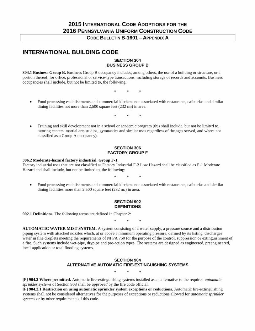
2015 INTERNATIONAL CODE ADOPTIONS FOR THE 2016 PENNSYLVANIA UNIFORM CONSTRUCTION CODE
CODE BULLETIN B-1601 – APPENDIX A
INTERNATIONAL BUILDING CODE
SECTION 304 BUSINESS GROUP B
304.1 Business Group B. Business Group B occupancy includes, among others, the use of a building or structure, or a
portion thereof, for office, professional or service-type transactions, including storage of records and accounts. Business
occupancies shall include, but not be limited to, the following:
* * *
Food processing establishments and commercial kitchens not associated with restaurants, cafeterias and similar
dining facilities not more than 2,500 square feet (232 m2) in area.
* * *
Training and skill development not in a school or academic program (this shall include, but not be limited to,
tutoring centers, martial arts studios, gymnastics and similar uses regardless of the ages served, and where not
classified as a Group A occupancy).
SECTION 306 FACTORY GROUP F
306.2 Moderate-hazard factory industrial, Group F-1.
Factory industrial uses that are not classified as Factory Industrial F-2 Low Hazard shall be classified as F-1 Moderate
Hazard and shall include, but not be limited to, the following:
* * *
Food processing establishments and commercial kitchens not associated with restaurants, cafeterias and similar
dining facilities more than 2,500 square feet (232 m2) in area.
SECTION 902 DEFINITIONS
902.1 Definitions. The following terms are defined in Chapter 2:
* * *
AUTOMATIC WATER MIST SYSTEM. A system consisting of a water supply, a pressure source and a distribution
piping system with attached nozzles which, at or above a minimum operating pressure, defined by its listing, discharges
water in fine droplets meeting the requirements of NFPA 750 for the purpose of the control, suppression or extinguishment of
a fire. Such systems include wet-pipe, drypipe and pre-action types. The systems are designed as engineered, preengineered,
local-application or total flooding systems.
SECTION 904 ALTERNATIVE AUTOMATIC FIRE-EXTINGUISHING SYSTEMS
* * *
[F] 904.2 Where permitted. Automatic fire-extinguishing systems installed as an alternative to the required automatic
sprinkler systems of Section 903 shall be approved by the fire code official.
[F] 904.2.1 Restriction on using automatic sprinkler system exceptions or reductions. Automatic fire-extinguishing
systems shall not be considered alternatives for the purposes of exceptions or reductions allowed for automatic sprinkler
systems or by other requirements of this code.

CODE BULLETIN B-1601 APPENDIX A
5
* * *
[F] 904.11 Automatic water mist systems. Automatic water mist systems shall be permitted in applications that are
consistent with the applicable listing or approvals and shall comply with Sections 904.11.1 through 904.11.3.
[F] 904.11.1 Design and installation requirements. Automatic water mist systems shall be designed and installed in
accordance with Sections 904.11.1.1 through 904.11.1.4.
[F] 904.11.1.1 General. Automatic water mist systems shall be designed and installed in accordance with NFPA 750 and the
manufacturer’s instructions.
[F] 904.11.1.2 Actuation. Automatic water mist systems shall be automatically actuated.
[F] 904.11.1.3 Water supply protection. Connections to a potable water supply shall be protected against backflow in
accordance with the International Plumbing Code.
[F] 904.11.1.4 Secondary water supply. Where a secondary water supply is required for an automatic sprinkler system, an
automatic water mist system shall be provided with an approved secondary water supply.
[F] 904.11.2 Water mist system supervision and alarms. Supervision and alarms shall be provided as required for
automatic sprinkler systems in accordance with Section 903.4.
[F] 904.11.2.1 Monitoring. Monitoring shall be provided as required for automatic sprinkler systems in accordance with
Section 903.4.1.
[F] 904.11.2.2 Alarms. Alarms shall be provided as required for automatic sprinkler systems in accordance with Section
903.4.2.
[F] 904.11.2.3 Floor control valves. Floor control valves shall be provided as required for automatic sprinkler systems in
accordance with Section 903.4.3.
[F] 904.11.3 Testing and maintenance. Automatic water mist systems shall be tested and maintained in accordance with the
International Fire Code.
Added new standard to Chapter 35 as follows:
NFPA 750-14 Standard on Water Mist Fire Protection Systems
SECTION 907 FIRE ALARM AND DETECTION SYSTEMS
907.2.11 Single- and multiple-station smoke alarms. Listed single- and multiple-station smoke alarms complying with UL
217 shall be installed in accordance with Sections 907.2.11.1 through 907.2.11.6 and NFPA 72.
* * *
[F] 907.2.11.3 Installation near cooking appliances. Smoke alarms shall not be installed in the following locations unless
this would prevent placement of a smoke alarm in a location required by Section 907.2.11.1 or 907.2.11.2:
1. Ionization smoke alarms shall not be installed less than 20 feet (6096 mm) horizontally from a permanently installed
cooking appliance.
2. Ionization smoke alarms with an alarm-silencing switch shall not be installed less than 10 feet (3048 mm)
horizontally from a permanently installed cooking appliance.
3. Photoelectric smoke alarms shall not be installed less than 6 feet (1829 mm) horizontally from a permanently
installed cooking appliance.
[F] 907.2.11.4 Installation near bathrooms. Smoke alarms shall be installed not less than 3 feet (914 mm) horizontally from
the door or opening of a bathroom that contains a bathtub or shower unless this would prevent placement of a smoke alarm
required by Section 907.2.11.1 or 907.2.11.2.
SECTION 2902 MINIMUM PLUMBING FACILITIES
[P] 2902.3 Employee and public toilet facilities. Customers, patrons and visitors shall be provided with public toilet
facilities in structures and tenant spaces intended for public utilization. The number of plumbing fixtures located within the
required toilet facilities shall be provided in accordance with Section 2902.1 for all users. Employees shall be provided with
toilet facilities in all occupancies. Employee toilet facilities shall be either separate or combined employee and public toilet
facilities.
Exception: Public toilet facilities shall not be required in:
1. Open or enclosed parking garages where there are no parking attendants.
2. Structures and tenant spaces intended for quick transactions, including takeout, pickup and drop-off, having a
public access area less than or equal to 300 square feet (28 m2).

CODE BULLETIN B-1601 APPENDIX A
6
INTERNATIONAL MECHANICAL CODE
SECTION 507 COMMERCIAL KITCHEN HOODS
(Modified from 2009 as follows)
507.2.1 Type I hoods. Type I hoods shall be installed where cooking appliances produce grease or smoke. Type I hoods shall
be installed over medium-duty, heavy-duty and extra-heavy-duty cooking appliances. Type I hoods shall be installed over
light-duty cooking appliances that produce grease or smoke.
INTERNATIONAL RESIDENTIAL CODE
CHAPTER 11 [RE] ENERGY EFFICIENCY
SECTION N1101 GENERAL
N1101.6 (R202) Defined terms. The following words and terms shall, for the purposes of this chapter, have the meanings
shown herein.
* * *
INSULATED SIDING. A type of continuous insulation with manufacturer-installed insulating material as an integral part of
the cladding product having a minimum R-value of R-2.
SECTION N1102 (R402) BUILDING THERMAL ENVELOPE
N1102.2.4 (R402.2.4) Access hatches and doors. Access doors from conditioned spaces to unconditioned spaces such as
attics and crawl spaces shall be weatherstripped and insulated to a level equivalent to the insulation on the surrounding
surfaces. Access shall be provided to all equipment that prevents damaging or compressing the insulation. A wood-framed or
equivalent baffle or retainer is required to be provided when loose-fill insulation is installed, the purpose of which is to
prevent the loose-fill insulation from spilling into the living space when the attic access is opened, and to provide a
permanent means of maintaining the installed R-value of the loose-fill insulation.
Exception: Vertical doors that provide access from conditioned to unconditioned spaces shall be permitted to meet
the fenestration requirements of Table R1102.1.2 based on the applicable climate zone specified in Chapter 3.
* * *
N1102.2.8 (R402.2.8) Floors. Floor framing-cavity insulation shall be installed to maintain permanent contact with the
underside of the subfloor decking.
Exception: The floor framing-cavity insulation shall be permitted to be in contact with the topside of sheathing or
continuous insulation installed on the bottom side of floor framing where combined with insulation that meets or
exceeds the minimum wood frame wall R-value in Table 1102.1.2 and that extends from the bottom to the top of all
perimeter floor framing members.
* * *

CODE BULLETIN B-1601 APPENDIX A
7
TABLE N1102.4.1.1 (402.4.1.1) AIR BARRIER AND INSULATION INSTALLATION
(Only the “Floor” section revised)
COMPONENT AIR BARRIER CRITERIA INSULATION INSTALLATION CRITERIA Floors (including above garage and
cantilevered floors)
The air barrier shall be installed at any
exposed edge of insulation.
Floor framing cavity insulation shall be
installed to maintain permanent contact
with the underside of subfloor decking, or
floor framing cavity insulation shall be
permitted to be in contact with the top side
of sheathing, or continuous insulation
installed on the underside of floor framing;
and extends from the bottom to the top of
all perimeter floor framing members.
* * *
N1102.1.3 (R402.1.3) R-value computation. Insulation material used in layers, such as framing cavity insulation, or
continuous insulation shall be summed to compute the corresponding component R-value. The manufacturer’s settled R-value
shall be used for blown insulation. Computed R-values shall not include an R-value for other building materials or air films.
Where insulated siding is used for the purpose of complying with the continuous insulation requirements of Table N1102.1.2,
the manufacturer’s labeled R-value for insulated siding shall be reduced by R-0.6.
* * *
TABLE R302.1(1) EXTERIOR WALLS
EXTERIOR WALL ELEMENT
MINIMUM FIRE-RESISTANCE RATING
MINIMUM FIRE SEPARATION DISTANCE
Walls Fire-resistance
rated 1 hour—tested in accordance with
ASTM E 119
or UL 263 with exposure from both sides
< 5 feet
Not fire-resistance
rated 0 hours 5 feet
Projections Not allowed N/A < 2 feet
Fire-resistance
rated 1 hour on the underside a, b 2 feet to < 5 feet
Not fire-resistance
rated
0 hours 5 feet
Openings in walls Not allowed N/A < 3 feet
25% maximum of
wall area 0 hours 3 feet
Unlimited 0 hours 5 feet Penetrations All Comply with Section R302.4 < 3 feet
None required 3 feet For SI: 1 foot = 304.8 mm. N/A = Not Applicable. a. Roof eave fire-resistance rating shall be permitted to be reduced to 0 hours on the underside of the eave if fireblocking is provided from the wall top plate to the underside of the roof sheathing. b. Roof eave fire-resistance rating shall be permitted to be reduced to 0 hours on the underside of the eave provided that gable vent openings are not installed.
SECTION R316 FOAM PLASTIC
R316.5.11 Sill plates and headers. Foam plastic shall be permitted to be spray applied to sill plates and headers or installed
in the perimeter joist space without the thermal barrier specified in Section R316.4 subject to all of the following:
1. The thickness of the foam plastic shall be not more than 31/4 inches (83 mm).
2. The density of the foam plastic shall be in the range of 0.5 to 2.0 pounds per cubic foot (8 to 32 kg/m3).
3. The foam plastic shall have a flame spread index of 25 or less and an accompanying smoke-developed index of 450
or less when tested in accordance with ASTM E 84 or UL 723.
* * *

CODE BULLETIN B-1601 APPENDIX A
8
SECTION R317 PROTECTION OF WOOD AND WOOD-BASED PRODUCTS AGAINST DECAY
R317.1.4 Wood columns. Wood columns shall be approved wood of natural decay resistance or approved pressure-
preservative-treated wood.
Exceptions:
1. Columns exposed to the weather or in basements where supported by concrete piers or metal pedestals
projecting 1 inch (25 mm) above a concrete floor or 6 inches (152 mm) above exposed earth and the earth is
covered by an approved impervious moisture barrier.
2. Columns in enclosed crawl spaces or unexcavated areas located within the periphery of the building when
supported by a concrete pier or metal pedestal at a height more than 8 inches (203 mm) from exposed earth and
the earth is covered by an impervious moisture barrier.
3. Deck posts supported by concrete piers or metal pedestals projecting not less than 1 inch (25 mm) above a
concrete floor or 6 inches (152 mm) above exposed earth.
* * *
SECTION R507 EXTERIOR DECKS
R507.1 Decks. Wood-framed decks shall be in accordance with this section or Section R301 for materials and conditions not
prescribed herein. Where supported by attachment to an exterior wall, decks shall be positively anchored to the primary
structure and designed for both vertical and lateral loads. Such attachment shall not be accomplished by the use of toenails or
nails subject to withdrawal. Where positive connection to the primary building structure cannot be verified during inspection,
decks shall be self-supporting. For decks with cantilevered framing members connections to exterior walls or other framing
members shall be designed and constructed to resist uplift resulting from the full live load specified in Table R301.5 acting
on the cantilevered portion of the deck.
* * *
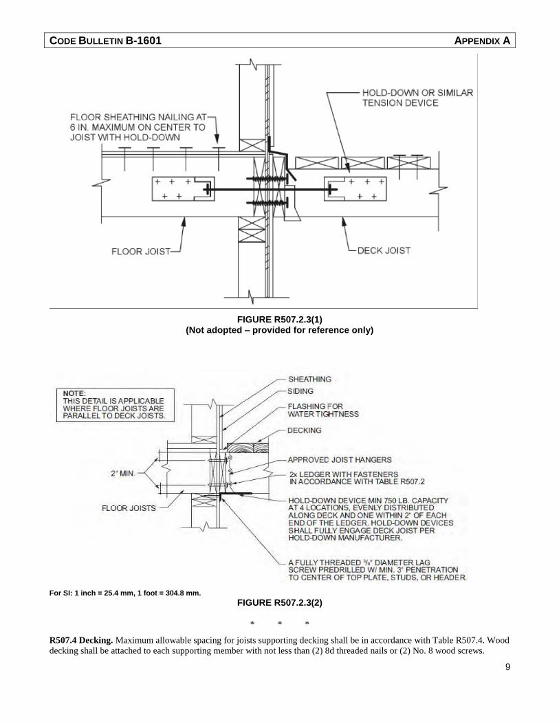
R507.2.4 Deck lateral load connection. The lateral load connection required by Section R507.1 shall be permitted to be in
accordance with Figure R507.2.3(1) or R507.2.3(2). Where the lateral load connection is provided in accordance with Figure
R507.2.3(1), hold-down tension devices shall be installed in not less than two locations per deck, within 24 inches of each
end of the deck. Each device shall have an allowable stress design capacity of not less than 1,500 pounds (6672 N). Where
the lateral load connections are provided in accordance with Figure R507.2.3(2), the hold-down tension devices shall be
installed in not less than four locations per deck, and each device shall have an allowable stress design capacity of not less
than 750 pounds (3336 N).
CODE BULLETIN B-1601 APPENDIX A
9
FIGURE R507.2.3(1) (Not adopted – provided for reference only)
For SI: 1 inch = 25.4 mm, 1 foot = 304.8 mm.
FIGURE R507.2.3(2)
* * *
R507.4 Decking. Maximum allowable spacing for joists supporting decking shall be in accordance with Table R507.4. Wood
decking shall be attached to each supporting member with not less than (2) 8d threaded nails or (2) No. 8 wood screws.

CODE BULLETIN B-1601 APPENDIX A
10
TABLE R507.4 MAXIMUM JOIST SPACING
Material type and nominal size Maximum on-center joist spacing
Perpendicular to joist Diagonal to joista
5/4-inch thick wood 16 inches 12 inches
2-inch thick wood 24 inches 16 inches
Plastic composite Per R507.3 Per R507.3
For SI: 1 inch = 25.4 mm a. Maximum angle of 45 degrees from perpendicular for wood deck boards
R507.5 Deck joists. Maximum allowable spans for wood deck joists, as shown in Figure R507.5, shall be in accordance with
Table R507.5. Deck joists shall be permitted to cantilever not greater than one-fourth of the actual, adjacent joist span.
R507.5.1 Lateral restraint at supports. Joist ends and bearing locations shall be provided with lateral restraint to prevent
rotation. Where lateral restraint is provided by joist hangers or blocking between joists, their depth shall equal not less than
60 percent of the joist depth. Where lateral restraint is provided by rim joists, they shall be secured to the end of each joist
with not less than (3) 10d (3-inch X 0.128-inch) nails or (3) No. 10 X 3-inch (76mm) long wood screws.
* * *
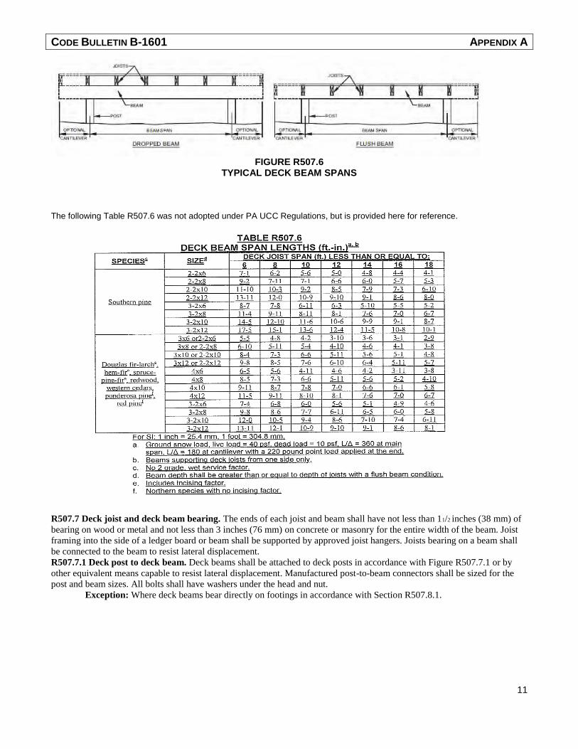
R507.6 Deck Beams. Maximum allowable spans for wood deck beams, as shown in Figure R507.6, shall be in accordance
with Table R507.6. Beam plies shall be fastened with two rows of 10d (3-inch 0.128-inch) nails minimum at 16 inches
(406 mm) on center along each edge. Beams shall be permitted to cantilever at each end up to one-fourth of the actual beam
span. Splices of multispan beams shall be located at interior post locations.
CODE BULLETIN B-1601 APPENDIX A
11
FIGURE R507.6
TYPICAL DECK BEAM SPANS
The following Table R507.6 was not adopted under PA UCC Regulations, but is provided here for reference.
R507.7 Deck joist and deck beam bearing. The ends of each joist and beam shall have not less than 11/2 inches (38 mm) of
bearing on wood or metal and not less than 3 inches (76 mm) on concrete or masonry for the entire width of the beam. Joist
framing into the side of a ledger board or beam shall be supported by approved joist hangers. Joists bearing on a beam shall
be connected to the beam to resist lateral displacement.
R507.7.1 Deck post to deck beam. Deck beams shall be attached to deck posts in accordance with Figure R507.7.1 or by
other equivalent means capable to resist lateral displacement. Manufactured post-to-beam connectors shall be sized for the
post and beam sizes. All bolts shall have washers under the head and nut.
Exception: Where deck beams bear directly on footings in accordance with Section R507.8.1.

CODE BULLETIN B-1601 APPENDIX A
12
FIGURE R507.7.1 DECK BEAM TO DECK POST
R507.8 Deck posts. For single-level wood-framed decks with beams sized in accordance with Table R507.6, deck post size
shall be in accordance with Table R507.8.
R507.8.1 Deck post to deck footing. Posts shall bear on footings in accordance with Section R403 and Figure R507.8.1.
Posts shall be restrained to prevent lateral displacement at the bottom support. Such lateral restraint shall be provided by
manufactured connectors installed in accordance with Section R507 and the manufacturers’ instructions or a minimum post
embedment of 12 inches(305 mm) in surrounding soils or concrete piers.
FIGURE R507.8.1
TYPICAL DECK POSTS TO DECK FOOTINGS
TABLE R507.8 DECK POST HEIGHT a
DECK POST SIZE MAXIMUM HEIGHT a
4X4 8’
4X6 8’
6X6 14’ For SI: 1 foot = 304.8 mm. a. Measured to the underside of the beam.
* * *

CODE BULLETIN B-1601 APPENDIX A
13
SECTION M1503
RANGE HOODS
M1503.4 Makeup air required. Exhaust hood systems capable of exhausting in excess of 400 cubic feet per minute (0.19
m3/s) shall be mechanically or naturally provided with makeup air at a rate approximately equal to the exhaust air rate. Such
makeup air systems shall be equipped with not less than one damper. Each damper shall be a gravity damper or an
electrically operated damper that automatically opens when the exhaust system operates. Dampers shall be accessible for
inspection, service, repair and replacement without removing permanent construction or any other ducts not connected to the
damper being inspected, serviced, repaired or replaced.
* * *
SECTION M1601
DUCT CONSTRUCTION
Modified only exception #3 as follows:
M1601.4.1 Joints, seams and connections. Joints of duct systems shall be made substantially airtight by means of tapes,
mastics, liquid sealants, gasketing or other approved closure systems. Closure systems used with rigid fibrous glass ducts
shall comply with UL181A and shall be marked 181A-P for pressure-sensitive tape, 181A-M for mastic or 181 A-H for heat-
sensitive tape. Closure systems used with flexible air ducts and flexible air connectors shall comply with UL 181B and shall
be marked 181B-FX for pressure-sensitive tape or 181B-M for mastic. Duct connections to flanges of air distribution system
equipment or sheet metal fittings shall be mechanically fastened. Mechanical fasteners for use with flexible nonmetallic air
ducts shall comply with UL 181B and shall be marked 181B-C. Crimp joints for round metal ducts shall have a contact lap of
at least 11/2 inches (38 mm) and shall be mechanically fastened by means of at least three sheet-metal screws or rivets
equally spaced around the joint. Closure systems used to seal metal ductwork shall be installed in accordance with the
manufacturer’s installation instructions.
Exceptions:
1. Spray polyurethane foam shall be permitted to be applied without additional joint seals.
2. Where a duct connection is made that is partially inaccessible, three screws or rivets shall be equally spaced
on the exposed portion of the joint so as to prevent a hinge effect.
3. Continuously welded and locking type longitudinal joints and seams in ducts operating at static pressures
less than 2 inches of water column (500 Pa) pressure classification shall not require additional closure
systems. For ducts having a static pressure classification of less than 2 inches of water column (500Pa),
additional closure systems shall not be required for continuously welded joints and seams and locking-type
joints and seams of other than the snap-lock and button-lock types.
INTERNATIONAL ENERGY CONSERVATION CODE
SECTION R202 GENERAL DEFINITIONS
INSULATED SIDING. A type of continuous insulation with manufacturer-installed insulating material as an integral part of
the cladding product having a minimum R-value of R-2.
* * *
SECTION R402 BUILDING THERMAL ENVELOPE
R402.1.3 R-value computation. Insulation material used in layers, such as framing cavity insulation, or continuous
insulation shall be summed to compute the corresponding component R-value. The manufacturer’s settled R-value shall be
used for blown insulation. Computed R-values shall not include an R-value for other building materials or air films. Where
insulated siding is used for the purpose of complying with the continuous insulation requirements of Table R402.1.2, the
manufacturer’s labeled R-value for insulated siding shall be reduced by R-0.6.
* * *

CODE BULLETIN B-1601 APPENDIX A
14
R402.2.4 Access hatches and doors. Access doors from conditioned spaces to unconditioned spaces such as attics and crawl
spaces shall be weatherstripped and insulated to a level equivalent to the insulation on the surrounding surfaces. Access shall
be provided to all equipment that prevents damaging or compressing the insulation. A woodframed or equivalent baffle or
retainer is required to be provided when loose-fill insulation is installed, the purpose of which is to prevent the loose-fill
insulation from spilling into the living space when the attic access is opened, and to provide a permanent means of
maintaining the installed R-value of the loose-fill insulation.
Exception: Vertical doors that provide access from conditioned to unconditioned spaces shall be permitted to meet
the fenestration requirements of Table R402.1.2 based on the applicable climate zone specified in Chapter 3.
* * *
R402.2.8 Floors. Floor framing-cavity insulation shall be installed to maintain permanent contact with the underside of the
subfloor decking.
Exception: The floor framing-cavity insulation shall be permitted to be in contact with the topside of sheathing or
continuous insulation installed on the bottom side of floor framing where combined with insulation that meets or
exceeds the minimum wood frame wall R-value in Table 402.1.2 and that extends from the bottom to the top of all
perimeter floor framing members.
* * *
TABLE 402.4.1.1 (N1102.4.1.1 ) AIR BARRIER AND INSULATION INSTALLATION
COMPONENT AIR BARRIER CRITERIA INSULATION INSTALLATION CRITERIA Floors (including above
garage and cantilevered
floors)
The air barrier shall be installed at any
exposed edge of insulation.
Floor framing cavity insulation shall be installed to maintain
permanent contact with the underside of subfloor decking,
or floor framing cavity insulation shall be permitted to be in
contact with the top side of sheathing, or continuous
insulation installed on the underside of floor framing; and
extends from the bottom to the top of all perimeter floor
framing members.
INTERNATIONAL EXISTING BUILDING CODE
SECTION 406 GLASS REPLACEMENT AND REPLACEMENT WINDOWS
406.3 Replacement window openings. Where windows are required to provide emergency escape and rescue openings in
Group R-2 and R-3 occupancies, replacement windows shall be exempt from the requirements of Sections 1029.2, 1029.3
and 1029.5 provided the replacement window meets the following conditions:
1. The replacement window is the manufacturer's largest standard size window that will fit within the existing
frame or existing rough opening. The replacement window shall be permitted to be of the same operating
style as the existing window or a style that provides for an equal or greater window opening area than the
existing window.
2. The replacement of the window is not part of a change of occupancy.
* * *
END OF DOCUMENT