Department of Electronics and Communication …diet.edu.in/QuestionBanks/II-BTECH-II-SEM/ECE.pdfII...
24
DADI INSTITUTE OF ENGINEERING & TECHNOLOGY (Approved by A.I.C.T.E., New Delhi & Affiliated to JNTUK, Kakinada) NAAC Accredited Institute An ISO 9001:2008, ISO 14001:2004 & OHSAS 18001:2007 Certified Institute. NH-5, Anakapalle – 531002, Visakhapatnam, A.P. Phone: 08924-221111 / 221122/9963981111, www.diet.edu.in, E-mail: [email protected] Department of Electronics and Communication Engineering II B.Tech (ECE) Sem-II QUESTION BANK Subject: Management Science (R13) Faculty: A. Kiran Kumar, Sr. Asst. Professor, MBA Department I UNIT 1. a) What is the significance of Hawthorne experiments for management? b) Define Management and explain its functions. 2. a) Define Management? Explain Henry Fayol’s principles of management b) Differentiate between behavioral approach and scientific approach to management. 3. a) Explain the nature of management. b) What are the challenges you have to face as a manager? 4. a) Describe the theory of scientific management and explain how it was criticized. b) What is matrix organization and what I its uniqueness. 5. a) Why is management considered as a profession and what factors make it a profession? b) Distinguish between Theory – X and Theory – Y 6. a) What is motivation? Explain Abraham Maslow’s needs Hierarchy theory. b) What do you mean by Functional organization structure? What are the advantages and disadvantages? II UNIT 1. a) Describe the basic procedure to be followed in adopting work study techniques for Sound results b) What is inventory? Explain the need for inventory control 2. a) What do you mean by EOQ? derive the formula for determining the EOQ. b) Define control charts and explain its types 3. a) What s meant by materials management? state its advantages and disadvantages.
-
Upload
truongkhanh -
Category
Documents
-
view
218 -
download
1
Transcript of Department of Electronics and Communication …diet.edu.in/QuestionBanks/II-BTECH-II-SEM/ECE.pdfII...

DADI INSTITUTE OF ENGINEERING & TECHNOLOGY (Approved by A.I.C.T.E., New Delhi & Affiliated to JNTUK, Kakinada)
NAAC Accredited Institute
An ISO 9001:2008, ISO 14001:2004 & OHSAS 18001:2007 Certified Institute.
NH-5, Anakapalle – 531002, Visakhapatnam, A.P.
Phone: 08924-221111 / 221122/9963981111, www.diet.edu.in, E-mail: [email protected]
Department of Electronics and Communication Engineering
II B.Tech (ECE) Sem-II QUESTION BANK
Subject: Management Science (R13)
Faculty: A. Kiran Kumar, Sr. Asst. Professor, MBA Department
I UNIT
1. a) What is the significance of Hawthorne experiments for management?
b) Define Management and explain its functions.
2. a) Define Management? Explain Henry Fayol’s principles of management
b) Differentiate between behavioral approach and scientific approach to management.
3. a) Explain the nature of management.
b) What are the challenges you have to face as a manager?
4. a) Describe the theory of scientific management and explain how it was criticized.
b) What is matrix organization and what I its uniqueness.
5. a) Why is management considered as a profession and what factors make it a profession?
b) Distinguish between Theory – X and Theory – Y
6. a) What is motivation? Explain Abraham Maslow’s needs Hierarchy theory.
b) What do you mean by Functional organization structure? What are the advantages and
disadvantages?
II UNIT
1. a) Describe the basic procedure to be followed in adopting work study techniques for Sound results
b) What is inventory? Explain the need for inventory control
2. a) What do you mean by EOQ? derive the formula for determining the EOQ.
b) Define control charts and explain its types
3. a) What s meant by materials management? state its advantages and disadvantages.

b) Explain the types of ABC analysis.
4. a) What is meant by integrated Materials Management? State its advantages
b) Discuss about various types of p chart,r chart.
5. What is statistical quality control? How is this important in operations management
III UNIT
1. a) State the importance and methods of job evaluation.
b) Define training and explain its methods.
2. a) What do you understand by marketing mix?
(b) Explain briefly the basic elements in marketing mix
3. a) Explain the functions of personnel management
b) Evaluate the different sources of recruitment
4. a) What do you understand by Human Resource Management?
b) Define Human Resource Development? Outline its concept.
5. a) Define Human Resource Management. Explain its functions
b) What are the differences between Human Resource Management and Personal Management and
Industrial Relations?
6. a) Discuss in brief about various wage payment plans? Are they relevant in present day Context.
b) What is product life cycle? Describe its stages.
IV UNIT 1. From the following information:
a) Draw the project network and find critical path.
b) Calculate earliest starting times and earliest finished times for each activity.
c) Determine Total, Free and Independent floats.
Activity Immediate Predecessor Duration
A - 3
B - 4
C A 5
D A 7
E B,C 3
F B,C,D 6
2. From the following information:

a) Draw the network
b) Find its critical path and project duration
c) Determine Total, Free and Independent Floats.
Activity Duration
1-2 5
1-3 4
2-4 6
3-4 2
4-5 1
4-6 7
5-7 8
6-7 4
7-8 3
3. From the following data crash the network and identify the optimum time of the project where the
indirect cost is estimated Rs. 60 per day.
Activity normal time Crash time Cost slope
1-2 9 6 20
1-3 8 5 25
1-4 15 10 30
2-4 5 3 10
3-4 11 6 15
4-5 2 1 40
4. From the following information:
(a) Draw the PERT network
(b) Find variance for each activity
(c) Find variance and standard distribution for critical path
(d) What is the probability that the project will be completed in 23 days?
(e) Find Total, Independent and Free floats?
Activity To Tm Tp
1-2 3 3 3
2-3 3 6 9
2-4 2 4 6
3-5 4 6 8
4-6 4 6 8
5-6 0 0 0
5-7 3 4 5
6-7 2 5 8

5. a) What is CPM? Discuss its advantages and limitations.
b) Distinguish between PERT and CPM.
6. a) What is pert? State its advantages and limitations
b) What is CPM? Explain its advantages.
V UNIT
1. (a) How do you formulate and implement strategy? Explain
(b) What is the need for corporate planning process?
2. (a) what are the factors of external and internal environmental to be considered
for formulating the strategy? Explain.
(b). Explain various generic strategy alternatives in detail
3. (a) Define strategic management and describe the process of strategic management.
(b) How do you carry out SWOT analysis for a manufacturing unit?
4. (a) What do you understand by the concept of strategy? Discuss the concept of Mission and Vision.
(b). Discuss corporate planning process.
5. (a). Explain various external environment scanning techniques used by the organization
(b) What is environmental scanning? How is this important in present day context.
VI UNIT
1. Write a notes on:
(a) Capability Maturity Model (b) Balanced Score card.
2. Write a notes on :
(a) Supply Chain Management b) Performance Management.
3 (a) What is Enterprise Resource Planning? Explain
(b) Explain the merits and demerits of Enterprise Resource Planning.
4. (a) define total quality management and explain its significance.
(b) Write notes on six sigma

5. Write short notes on:
(a) Management Information System (b) Bench Marking.
6. Discuss the following;
a) Supply Chain Management b) Enterprise Resource Planning
DADI INSTITUTE OF ENGINEERING & TECHNOLOGY (Approved by A.I.C.T.E., New Delhi & Affiliated to JNTUK, Kakinada)
NAAC Accredited Institute
An ISO 9001:2008, ISO 14001:2004 & OHSAS 18001:2007 Certified Institute.
NH-5, Anakapalle – 531002, Visakhapatnam, A.P.
Phone: 08924-221111 / 221122/9963981111, www.diet.edu.in, E-mail: [email protected]
Department of Electronics and Communication Engineering
Academic Year : 2017-2018
Name of the Faculty : A.N.S.ANUSHA
Designation : Asst. Professor
Department : ECE
Year/Semester : II –II Semester
Subject : PULSE and DIGITAL CIRCUITS
QUESTION BANK
UNIT-I
1. a) Prove that a low pass circuit acts as an integrator. Derive an expression for the output voltage levels
under steady state conditions of a low pass circuit excited by a ramp input.(5M)
b) Explain RLC ringing circuit with a neat sketch.(5M)
2. a) Draw the output waveform of an RC high-pass circuit with a square wave input under different time
constants. Derive the expression for percentage of tilt. (5M)
b) What is an attenuator? How can an uncompensated attenuator be modified as a compensated
attenuator. Give the comparison between perfect compensation, under compensation and over
compensation. (5M)
3. a) Derive an expression for the output of low pass RC circuit excited by a step input.Draw the output for
different time constants.(5M)
b) Draw the response of an RC high pass circuit when applied with exponential input. Explain the
response for different time constants. (5M)
4. a) An RC low-pass filter is fed with a symmetrical square wave. The peak-to-peak amplitude of the
input waveform is 10 V and its average value is zero. It is given that RC=T/2 where T is the period of
the square wave. Determine the peak-to-peak amplitude of the output waveform. (5M)
b) Prove that et = T/2RC for ramp as input to the High pass RC-Circuit? (5M)
5. a) Explain the working principle of rate-of-rise amplifier? (5M)
b) Explain the working of attenuator as a CRO Probe? (5M)

UNIT-II
1. a) Give the circuits of different types of shunt clippers and explain their operation with
the help of their transfer characteristics .(5M)
b) State and prove clamping circuit theorem.(5M)
2. a) Write short notes on practical clamping circuits. (5M)
b) A voltage signal of (10 Sinwt) is applied to the circuit with ideal diodes shown in figure below.
Estimate the maximum & minimum values of output waveform and maximum current through each diode. Also
draw the input-output waveforms with proper explanation.(5M)
3. a)Draw the basic circuit diagram of negative peak clamper circuit and explain its Operation.
b) Give some applications of clipping & Clamping circuits. (5M)
4. a) With neat circuit diagram, explain the working of an emitter coupled clipper. (5M)
b) Explain the clamping circuit considering the source resistance and the diode forward resistance.
(5M)
5. a) A symmetrical 50 Hz square wave whose peak to peak excursions are ± 100 V with
respect to ground is to be positively clamped at 25 V. Draw the necessary circuit diagram and output
waveform for this purpose. (5M)
b) Design a diode clamper to restore the negative peaks of the input signal to zero level.
Use a silicon diode with Rf= 50 Ω and Rr= 400 kΩ. The frequency of the input signal
is 5 kHz.(5M)
UNIT –III
1. Explain the terms pertaining to transistor switching characteristics.
i) Rise time.[2M] ii) Delay time. [2M] iii) Turn-on time.[1M]
iv) Storage time.[2M] v) Fall time.[2M] vi) Turn-off time.[1M]
2. a) Describe the sequence of events in an n-p-n transistor to change from cutoff to saturation and vice versa.
How does temperature affect the saturation junction of a transistor? (5M)
b) Briefly discuss the influence of breakdown voltages on the choice of supply voltage in a transistor
switch. (5M)
3. a) Design a Schmitt trigger circuit using npn silicon transistors with VBE = 0.7V, VCE(sat) = 0.2V, hfe(min) = 60
and Ic(ON)= 3mA to meet the following specifications: Vcc =12V, upper threshold voltage, VUT= 4V, lower
threshold voltage,VLT=2V. (5M)
b) What are transpose capacitors? Explain how the commutating capacitors will increase the speed of a fixed-
bias binary. (5M)
4. a) With neat circuit diagram, Explain the working of fixed bias bistable multi vibrator. (5M)
b) Calculate the component values of a mono stable multi vibrator developing an output pulse of 500 μs
duration. Assume hfe(min) = 25, ICE(min)= 5 mA, VCC= 10 V and VBB = -4V. (5M)
5. a) Draw the circuit of a bistable multivibrator with symmetrical collector triggering. (5M)

b)What are commutating capacitors? Show a symmetrical triggering arrangement for bi-stable multivibrator
and explain its working. (5M)
UNIT -IV
1. a) Explain the operation of a Monostable multivibrator and derive for the pulse width with necessary
waveforms & circuirts. (5M)
b) Design a collector coupled astable multivibrator using NPN silicon transistors with hfe=40, rbb=200ohms
supploied with Vcc=10V and circuit component values are Rc=1.2Kohms and C=270 pF. (5M)
2. a) Draw the circuit diagram of an astable multivibrator and obtain all the steady state voltages and currents.
Show how it acts as a voltage to frequency converter. (5M)
b) Design and draw a collector-coupled ONE-SHOT using silicon npn transistors with hFE(MIN) =20. In
stable state, the transistor in cut-off has VBE = -1V and the transistor in saturation has base current, IB which is
50% excess of the IB(MIN) value. Assume VCC = 8V, IC(SAT) =2mA, delay time = 2.5ms & R1 = R2. Find RC, R,
R1, C and VBB . (5M)
3. a) Design a stable multi vibrator to generate a square wave of 1 kHz frequency with a duty cycle of 25%
using silicon n-p-n transistors with hFE(MIN) = 40. (5M)
b) Design a collector coupled one-shot with a gate width of 3 ms using NPN transistors Assume necessary
data. (5M)
4. Explain the operation of a Monostable multivibrator and derive for the pulse width with necessary
waveforms & circuirts.[10M]
5. a) Derive the equation for voltage-to-frequency converter when a stable multi vibrator is used as a basic
circuit. (5M)
b) The Schmitt trigger circuit also called sinusoidal to square converter? Explain the working principle. (5M)
UNIT -V
1. Explain the working of a transistor Bootstrap sweep circuit and derive expression
for the slope sweep error. (10M)
2. a) Why the time base generators are called sweep circuits? Give most important
applications of time –base generators. (5M)
b) What are the different methods of generating time-base waveforms? Explain about
each briefly. (5M)
3. Explain the working of Transistor Miller sweep circuit. What are its advantages over
Bootstrap sweep circuits? (5M)
4. a) Define and derive the terms slope error, displacement error and transmission error. (5M)
b) How is deviation of linearity expressed? What do you mean by sweep time and
restoration time? (5M)
5. Explain the basic principles of Miller and Bootstrap time-base generators. Give the comparison of both
the generation methods. (10M)
UNIT-VI
1. a) Draw the circuit diagram of a unidirectional sampling gate which delivers an output
only at the coincidence of a number of control voltages and explain its working. (5M)
b) Explain how to cancel the pedestal in a sampling gate with suitable circuit diagram. (5M)

2. a) Explain the function of a sampling gate used in Sampling Scopes also explain how
sampling gate is used in chopping amplifiers. (5M)
b) Explain how the loading of the control signal is reduced when the number of inputs
increases in a sampling gate. (5M)
3. a) Explain about unidirectional diode sampling gate. Write its advantages and
disadvantages. (5M)
b) With neat circuit diagram, Explain bidirectional sampling gate using transistors. (5M)
4. a) What is meant by synchronization? Why it is needed? Explain. (5M)
b) Explain about four diode sampling gate. (5M)
5. a) Explain about phase delay and phase jitters. (5M)
b) Explain how pedestal can be reduced in gate circuit. (5M)

DADI INSTITUTE OF ENGINEERING & TECHNOLOGY (Approved by A.I.C.T.E., New Delhi & Affiliated to JNTUK, Kakinada)
NAAC Accredited Institute
An ISO 9001:2008, ISO 14001:2004 & OHSAS 18001:2007 Certified Institute.
NH-5, Anakapalle – 531002, Visakhapatnam, A.P.
Phone: 08924-221111 / 221122/9963981111, www.diet.edu.in, E-mail: [email protected]
Department of Electronics and Communication Engineering
II B.Tech (ECE) Sem-II QUESTION BANK
Subject:Analog Communications (R16)
Faculty: Archana .B .T, Assistant Professor, ECE Department
UNIT 1
1. What is the principle of amplitude modulation? Derive the expression for the AM wave and draw its
spectrum.6M
b) Explain the benefits of suppressed carrier AM system.4M
2. Explain with the help of diagram how a square modulator is used to generate AM.6M
b) Compare low level and high level modulation.4M
3. Derive the equation and power relation of a single tone modulation of AM system. 6M b) What is the
need for modulation? Explain the main advantages of modulation?4M
4. Explain the working of an envelope detector. 6M
b) A 400W carrier is modulated to a depth of 75%. Calculate the total power in the modulated wave.4M
5. With a neat block diagram, explain the operation of Frequency division multiplexing technique. 5M
b) Explain about diagonal clipping in a diode detector. How it can be eliminated?5M
6. Draw the Envelope detector and illustrate the process of detection of AM wave?5M
b)Draw and explain switching modulator along with the related transfer characteristics and equation.5M
UNIT 2
1. Derive the expression for SSB containing upper sideband in time domain. 6M
b) Explain the phase discrimination method for generating SSB.4M
2. Draw the circuit diagram for balanced, ring modulator and explain its operation indicating all the
waveforms and spectrums.6M
b) List Application of different AM systems?4M
3. With neat diagrams, explain about the VSB modulation system and also explain its applications. 6M
b) Compare AM, D.S.B-SC, S.S.B-SC and V.S.B transmission.4M
4. With block diagram and relevant equations explain the coherent detection of a DSB-SC wave. What is its
disadvantage? Explain the synchronous receiving system.10M

5. Explain Coherent detection of DSB-SC Modulated waves.5M
b) Explain COSTAS Loop.5M
Unit 3
1. Briefly explain about the spectra of NBFM and WBFM. 4M
b) Explain the demodulation of F.M signal with the help of PLL.6M
2. Define angle modulation? Explain different types of angle modulations with mathematical expressions.
5M
b) Compare F.M and A.M.5M
3. With a neat block diagram explain the Armstrong method of FM generation. 6M
b) Draw the phasor diagram of narrow band FM.4M
4. Explain the operation of a) Balanced Frequency discriminator.5M
b)Zero crossing detector.5M
5. Explain the spectrum analysis of sinusoidal FM wave.5M
b)Explain the generation of FM using direct method.5M
Unit 4
1. a) With the aid of the block diagram explain TRF receiver. Also explain the basic super heterodyne
principle. 6M
b) List out the advantages and disadvantages of TRF receiver.4M
2. a) What is the need for amplitude limiter in FM Receiver? Explain in detail. 5M
b) What are the salient features of broadcast radio receivers? Explain in detail.5M
3. a) Explain the function of Mixer stage in FM Receiver. 5M
b) What are the main functions served by an I.F amplifier? Explain in detail.5M
4. With neat block diagram, explain the operation of super heterodyne F.M. receiver.10M
5. a) How F.M Receivers are different from A.M receivers? Explain in detail.6M
b) Define the terms sensitivity, selectivity and fidelity of a radio receiver.4M
UNIT 5
1. a) What is FM threshold effect? How to achieve threshold reduction in FM system?6M b) Discuss the
noise performance of AM system using envelop detection?4M
2. a) What is noise? Explain the difference between thermal noise and shot noise. 5M
b) Explain about noise effect in DSB-SC and obtain necessary expression for figure of merit.5M
3. a) Explain about the noise performance of an FM receiver.5M
b) Derive the expression for the figure of merit of an SSB-SC System.5M
4. a) Why pre-emphasis and de-emphasis are needed in F.M but not in A.M? Explain. 5M b) Explain
about noise effect in AM and obtain expression for figure of merit.5M

5. a) Write short notes (i) Average noise figure. (ii) Average Noise Temperature.5M
b) Define White noise and Shot noise.5M
6. a) Define the following along the related equations (i) noise equivalent bandwidth (ii) narrow band noise
(iii) ideal band pass filtered noise.10M
Unit 6
1. a) Define Pulse Amplitude Modulation (PAM).2M
b)Explain the generation of PAM. 8M
2. List out the drawbacks of pulse amplitude modulated signal? 4M
b) With neat sketch explain the generation of PPM from PWM.6M
3. Explain Time Division Multiplexing.6M
b) Compare merits and demerits of TDM and FDM.4M
4. a) Compare continuous wave and pulse modulation techniques.5M
b) Write short notes on transmission bandwidth of PAM.5M
5. Compare PAM, PWM and PPM systems. 5M
b) Explain the single polarity and double polarity PAM.5M

DADI INSTITUTE OF ENGINEERING & TECHNOLOGY (Approved by A.I.C.T.E., New Delhi & Affiliated to JNTUK, Kakinada)
NAAC Accredited Institute
An ISO 9001:2008, ISO 14001:2004 & OHSAS 18001:2007 Certified Institute.
NH-5, Anakapalle – 531002, Visakhapatnam, A.P.
Phone: 08924-221111 / 221122/9963981111, www.diet.edu.in, E-mail: [email protected]
Department of Electronics and Communication Engineering
II B.Tech. II Sem- CONTROL SYSTEMS QUESTION BANK
Academic Year :2017-2018
Name of the Faculty : M Rajendra Prasad
Designation : Asst.Professor,EEE Dept
Department :ECE
Year/Semester :II YEAR– II SEMESTER
Subject : Control Systems
UNIT-1
1. a) Define control systems. Explain the difference between closed loop and open looped system with a
suitable example. [4M]
b) What do you mean by the sensitivity of the control system and discuss the effect of feedback on
sensitivity. [6M]
2. a) What are the characteristics of negative feedback [4M]
b) Draw the free body diagram and write the differential equations describe the dynamics of the system
shown in below figure and obtain the transfer function X2(s)
F(s) [6M]
3. a) Write the force balance equation of ideal dashpot [4M]
b) Find the transfer function θ(s)
T(s) [6M]
.
4. a) Write the differential equation of the mechanical system shown in figure below. [4M]
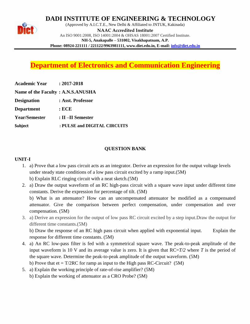
b) Obtain the transfer function of the figure shown below. [6M]
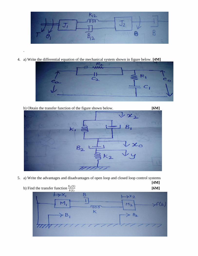
5. a) Write the advantages and disadvantages of open loop and closed loop control systems
[4M]
b) Find the transfer function X2(S)
F(S) [6M]

UNIT-2
1. a) What are characteristics of servo motor. [4M]
b) Using block diagram reduction technique find closed loop transfer function of the system whose
block diagram is shown below by applying conditions 1) R1=0 2) R2=0
[6M]
2. a) Derive the transfer function of field controlled DC servo motor [6M]
b) State and explain the Mason’s gain formula [4M]
3. a) Compare AC and DC servomotor [4M]
b) Draw the equivalent signal flow graph for the figure shown below and determine the C(s)
R(s) Mason’s
gain formula [6M]
4. a) Explain the advantages of signal flow graph over block diagram representation. [4M]
b) Derive the transfer function of field controlled AC servo motor [6M]
5. a) What are the advantages of transfer function representation of a system [4M]
b) Find the transfer function C(S)
R(S) [6M]

UNIT-3
1. a) Mention two advantages of generalized error constants over static error constants [4M]
b) The open loop transfer function of a servo motor with unity feedback is G s =10
s(0.1s+1) . Evaluate the
static error constants of the system. Obtain the steady state error of a system when subjected to an input
given by the polynomial r t = a0 + a1t +a2
2t2
[6M]
2. a) What is meant by step input, ramp input and impulse input. How do you represent them graphically?
[4M]
b) A unity feedback control system has its open loop transfer function given by G s =(4s+1)
(4s2).
Determine an expression for the time response when the system is subjected to 1) unit impulse input
function 2) unit step input function. [6M]
3. a) Define the error constants KP , KV , Ka [4M]
b) Derive the response of a standard under damped 2nd
order system for unit step input.
[6M]
4. a) Draw the unit step response of a 1st order system and explain. [4M]
b) Determine the step, ramp and parabolic error constants of the following unity feedback control system
whose open loop transfer function is given by
G s =500
1+5s (1+10s) [6M]
5. a) Write short notes on steady state error [4M]
b) Explain the effect of proportional control action on the performance of second order system
[6M]
UNIT-4
1. a) What is routh stability criterion [4M]
b) Determine the value of ‘ K’ such that the roots of the characteristic equation given below lie to the
left of the line s= -1, s3 + 10s2 + 18s + K = 0 [6M]
2. a) What are asymptotes? How will you find the angle of asymptotes. [4M]
b) Draw the root locus plot for a system having open loop transfer function is G s =K
s s+1 (s+5)
[6M] 3. a) Explain about the effects of adding zeros to G(s) H(s) on the root loci [4M]
b) Explain the procedure to draw the root locus of a given transfer function [6M]

4. a) For a unity feedback system with open loop transfer function G s H s =K
s s+4 (s+6) Find the range of
K for which the system will be stable using RH criterion. [4M]
b) Explain the routh criterion with an example and what are its limitations [6M]
5. a) Explain the advantages of root locus technique [4M]
b) Using routh Hurwitz criterion determine the stability of closed loop system that has the following
characteristic equation and also determine the number of roots that are in the right half of s-plane and on
the imaginary axiss4 + s3 + 3s2 + 2s + 5 = 0 [6M]
UNIT-5
1. a) What are the advantages of bode plot. [4M]
b) Find the gain margin and phase margin of the system if the open loop transfer function is G s =0.5
s2+3s+2 [6M]
2. a) Define resonant peak and bandwidth [4M]
b) Define various frequency domain specifications [6M]
3. a) What is phase and gain crossover frequency [4M]
b) Construct bode plot for the system whose open loop transfer function is given below, G s H s =4
s 1+0.5s (1+0.08s) [6M]
4. a) Define resonant peak and bandwidth [4M]
b)Find the gain margin and phase margin of the system if the open loop transfer function is G s =10
s(s+1) [6M]
5. a) Define resonant frequency and cut off rate [4M]
b) Find resonant peak, resonant frequency, bandwidth of the unity feedback system whose open loop
transfer function is G s =1
s2+6s+5 [6M]
UNIT-6
1. a) Define controllability and Observability [4M]
b) Define state transition matrix and explain its properties with examples. [6M]
2. a) For the system given below obtain total response [4M]
X = 0 1
−2 −1 X +
01 u(t) where x1(0) = 1, x2(0) = 0, u t = 1
b) Why compensation is necessary in feedback control system. [6M]
3. a) The transfer function of control system is given by Y(s)
U(s)=
s+2
(s3+9s2+26s+24) check controllability and
Observability. [4M]
b) Explain about lead compensator [6M]
4. a) A system is characterized by the following state space equation.
x1 x2
= −3 1−2 0
x1x2
+ 01 u(t) ; t>0
Y = 1 0 x1x2
Find the transfer function of the system. [4M]
b) Compute state transition matrix of above system. [6M]
5. a) What is meant by Observability [4M]
b) Determine the state and output equations in vector matrix form for the system whose transfer function
is given by 𝐺 𝑠 =(s+3)
s(s2+3s+2) [6M]

DADI INSTITUTE OF ENGINEERING & TECHNOLOGY (Approved by A.I.C.T.E., New Delhi & Affiliated to JNTUK, Kakinada)
NAAC Accredited Institute
An ISO 9001:2008, ISO 14001:2004 & OHSAS 18001:2007 Certified Institute.
NH-5, Anakapalle – 531002, Visakhapatnam, A.P.
Phone: 08924-221111 / 221122/9963981111, www.diet.edu.in, E-mail: [email protected]
Department of Electronics and Communication Engineering
II B.Tech (ECE) Sem-II QUESTION BANK
Subject: Electronic Circuit Analysis (R16)
Faculty: P.Poorna Priya, Assistant Professor, ECE Department
Unit-I
1. a) Sketch the circuit of a Common Source amplifier. Derive an expression for the Voltage gain. (5) b) The h-parameters of the transistor used in CE amplifier are hfe= 50, hie=1.1KΩ, hre= 2.5×10⁻⁴, hoe = 24µA/V. Find out current gain and voltage gains with and without source resistance , input and output impedances , given that RL= 10 K and RS= 1 K (5)
2. a) State Miller's theorem. Explain its significance in transistor circuit analysis. (5) b) For the Common Gate amplifier, derive expressions for voltage gain, input impedance and output impedance. Neglect capacitances. (5)
3. a) Draw the circuit diagram of Common Drain amplifier and derive an expression for its Voltage gain. (5) b) Explain the frequency response of CE amplifier and Gain bandwidth product. (5)
4. a) Draw the equivalent diagram of a single stage CE amplifier at high frequencies. Derive the expression for gain under short circuited load conditions. (5) b) When a Ge PNP transistor is biased at 2mA, 15V, it has a base width of 1 micron. Find Ce and fT if DB=47cm2/sec. (5)
5. a) Draw the High frequency model of a Transistor. Derive the relationship between high frequency and low frequency parameters. (5) b) Compare, CS, CG, and CD amplifier circuits at high frequencies. (5)
Unit-II
1. a) Explain the classification of amplifiers(5) b.) Explain methods of coupling. (5)
2. a) Explain the analysis of Cascaded transistor amplifier. (5) b) What are its advantages? (5)
3. a) Give the analysis of two stage RC coupled amplifier(5) b) What are its advantages? (5)
4. a) Explain the analysis of Darlington amplifier. (5) b) Explain the analysis of Cascode amplifier. (5)
5. a) Explain the analysis of Boot-strap amplifier. (5) b) Explain the analysis of Differential amplifier using BJT. (5)

Unit-III
1. a) Discuss quantitatively about the effect of negative feedback on i) Gain ii) Bandwidth iii) Distortion v) Input resistance and vi) output resistance. (10)
2. a) Draw the circuit diagram of a current series feedback amplifier. Derive expressions to show the effect of negative feedback on input & output impedances (6) b) Calculate Transconductance with feedback. (4)
3. a) Draw the circuit diagram of a voltage series feedback amplifier. Derive expressions to show the effect of negative feedback on input & output impedances (6) b) Calculate Voltage gain with feedback. (4)
4. a) Draw the circuit diagram of a current shunt feedback amplifier. Derive expressions to show the effect of negative feedback on input & output impedances (6) b) Calculate Current gain with feedback. (4)
5. a) Draw the circuit diagram of a Voltage shunt feedback amplifier, Derive expressions to show the effect of negative feedback on input & output impedances(6) b) Calculate Transresistance with feedback. (4)
Unit-IV0
1. a) What are the differences between an oscillator and an amplifier? Explain the operating principle of an oscillator. (5) b) Explain frequency stability and amplitude stability. (5)
2. a) Draw and explain the operation of Colpitt’s oscillator and derive its expression for frequency of oscillations. (7) b.) Explain briefly about Crystal Oscillator (3)
3. a) Draw and explain the operation of Hartley oscillator and derive its expression for frequency of oscillations. (7) b) Compare Colpitt’s and Hartley Oscillators.(3)
4. a) Draw and explain the operation of Wein Bridge oscillator and derive its expression for frequency of oscillations. (7) b) What are the advantages of a crystal oscillator over an LC oscillator? (3)
5. a) Draw and explain the operation of RC Phase shift oscillator and derive its expression for frequency of oscillations. (6) b) Differentiate between LC and RC oscillators? (4)
Unit-V
1. a) Classify large signal amplifiers based on its operating point. Distinguish these amplifiers in terms of the conversion efficiency.(5) b) Draw the push-pull power amplifier circuit. Derive the expression for the output current in push-pull amplifier with base current as Ib= Ibm sinωt. (5)
2. a) What is Harmonic distortion in transistor amplifier circuits? Discuss second harmonic distortion. (5) b) A single transistor is operating as an ideal class B amplifier with a 500 load. A dc meter in the collector circuit reads 10mA. How much signal power is delivered to the load? (5)
3. a) Explain the analysis of Class-A amplifier. (5) b) Explain about Class AB amplifier. (5)
4. a) Write short notes on requirement and types of heat sinks for power dissipation in large signal amplifiers. (5) b) With the help of a neat circuit diagram, explain the operation of a complementary symmetry configured class B power amplifier. (5)
5. a) Derive the expressions for maximum Theoretical efficiency for (i) Transformer coupled

(ii) Series fed amplifiers. (6) b) What are their advantages and disadvantages? (4)
Unit-VI
1. a) Draw the circuit diagram and small signal AC equivalent circuit of a single tuned amplifier (using BJT) with the tank circuit connected at the input side.(5) b) With a neat diagram show how to cascade tuned amplifiers and determine gain and bandwidth? (5)
2. a) What is synchronous tuning? Derive an expression for bandwidth of an n-stage synchronously tuned amplifier? (5) b) Show that for an ’n’ stage synchronously tuned amplifier; maximum bandwidth is obtained when the single stage gain is 4.34 dB. (5)
3. a) Derive an expression for bandwidth of a capacitive coupled tuned amplifier in CE configuration. Make necessary assumptions and mention them. (7) b) What are staggered tuned amplifiers? (3)
4. a) Draw the circuit diagram of a Double tuned amplifier. Draw and explain in detail the frequency response for different values of coefficient of coupling (K) i.e. K=1, K= 1.5, K=2 and also (7) b) Explain what is Loose coupling and Tight coupling? (3)
5. a) Discuss the necessity of stabilization circuits in tuned amplifiers. (5) b) Explain the principle and working of wide band amplifiers. (5)

DADI INSTITUTE OF ENGINEERING & TECHNOLOGY (Approved by A.I.C.T.E., New Delhi & Affiliated to JNTUK, Kakinada)
NAAC Accredited Institute
An ISO 9001:2008, ISO 14001:2004 & OHSAS 18001:2007 Certified Institute.
NH-5, Anakapalle – 531002, Visakhapatnam, A.P.
Phone: 08924-221111 / 221122/9963981111, www.diet.edu.in, E-mail: [email protected]
Department of Electronics and Communication Engineering
QUESTION BANK
Name of faculty: Mr. P. Ram Prasad Subject: EMWTL
Year: II - II-Semester Branch: ECE
Regulation: R16 Academic Year: 2017-2018
UNIT – I: Electrostatics
1. a. Point charges 4 mc and -3 mc are located at (2, 1, -3) and (-1, -2, 4) respectively. Calculate the electric
force on a 12 nc charge located at (0, 3, 1) and the electric field intensity at that point.
5M
b. State the applications of Gauss Law with respect to a) Point charge b) Infinite line charge 5M
2. a. Derive an expression for the electric field intensity due to a finite length line charge along
the Z- axis at an arbitrary point Q( x,y,z). 5M
b. The finite sheet 0 ≤ x ≤ 1 and 0 ≤ y ≤ 1 on the z =0 plane has a charge density ρs = xy(x2
+ y2 + 25 )
3/2
nC/m2 Find 5M
i. The total charge on the sheet
ii. The electric field at (0,0,5)
iii. The force experienced by a -1nC charge located at (0, 0, 5).
3 a. Briefly explain Dielectric constant and its strength. 5M
b. Explain about continuity equation and relaxation time. 5M
4. a. Explain about the parallel plate capacitor and coaxial capacitor with necessary equations. 5M
b. With necessary equations explain poisson’s and Laplace’s equation. 5M
5. a. If D = 2x2ax + ay + 2z
2 pC/m
2. Derive volume charge density. 5M
b. Give the Maxwell’s equations for electrostatic fields. 5M
6. a. Explain about Electric flux density. Determine D at (4,0,3) if there is a point charge -5П mC at (4,0,0)
and a line charge at 3П mC/m along the y-axis. 5M
b. Write about convection current and conduction current. 5M
UNIT – II: Magnetostatics & Maxwell’s Equations for Time Varying Fields.
1. a. Derive expression for magnetic field at any point on the axis at a distance ‘h’ from the centre of a circular
loop of radius ‘a’ and carrying current ‘I’. 5M

b. State and explain Biot – Savarts law. Give the expressions of Biot – Savarts law for line, surface and
volume currents. 5M
2. a. State Ampere’s circuit law and explain. Give its applications. 6M
b. Explain about inconsistency in Ampere’s Law. 4M
3. a. A circular loop located on x2 + y
2 = 9 and z = 0 carries a direct current of 10A along aф. Determine H at
(0, 0, 4) and (0, 0, -4). 5M
b. With necessary equations explain about Magnetic scalar and Vector potential. 5M
4. Explain about the following
i. Force on a charged particle. 5M
ii. Force on a current element. 5M
5. a. Write about the following Dielectric – Dielectric Boundary Condition and Conductor dielectric
boundary condition. 5M
b. State the Faraday’s Law and explain briefly. 5M
6. a. State all Maxwell’s equations in differential and integral form for time varying fields. 5M
b. Explain the concept displacement current and derive its necessary equations. 5M
UNIT – III: EM Wave Characteristics - I
1. Define and explain the terms
i. Skin Depth 4M
ii. Intrinsic Impedance of free space 3M
iii. Phase Constant. 3M
2. a. Derive the expression for attenuation and phase constants of uniform plane wave. 5M
b. Prove that E and H are perpendicular to each other in uniform plane waves. 5M
3. Derive the expression for wave equation in
i. Lossless Dielectric 4M
ii. Good Conductors 3M
iii. Free Space 3M
4. A plane wave with E = 2 V/m and has a frequency of 300MHz is moving in free space impinging on thick
copper sheet located perpendicular to the direction of the propagation. Find
i. E and H at the plane surface 4M
ii. Depth of penetration 3M
iii. Surface Impedance 3M
5. a. In a lossless medium for which η = 60П, µr = 1 and H = - 0.1cos (ωt - z) ax + 0.5 sin (ωt - z)ay A/m.
Calculate εr, ω and E. 5M
b. An elliptical polarized wave has an electric field of E = sin (ωt - ßz) ax + 2 sin (ωt – ßz + 750)ay V/m.
Find the power per unit area conveyed by the wave in free space. 5M
UNIT-IV: EM Wave Characteristics - II
1. a. What is Brewster angle? Derive the expression for the same. 5M
b. Discuss about power loss in plane conductor. 5M
2. a. State and prove the critical angle theorem. 5M

b. Derive an expression for reflection when a wave is incident on a dielectric obliquely with parallel
polarization. 5M
3. a. State and prove Poynting theorem. 5M
b. For good dielectric derive the expression for α, ß, v and η. 5M
4. a. Find the depth of penetration ᵟ of an EM wave in copper at f = 60Hz and f = 100MHz. For copper σ = 5.8
x 107 mho/m, εr = 1 and µr = 1. 5M
b. Prove that E i = - E r when the wave is normal incidence on a perfect conductor. 5M
5. a. A plane wave travelling in air is normally incident on a material with µr = 1 and εr = 4. Find the reflection
and transmission coefficient. 5M
b. Define and derive the transmission coefficient of a wave incidence in normal on dielectric. 5M
UNIT – V: Transmission Line – I
1. a. Derive the relationship between the primary constants and secondary constants in a transmission line.
5M b. What is meant by Inductive loading? What are its advantages and disadvantages? 5M
2. a. Show that a transmission line will be distortion less free if RC = LG 5M
b. A high frequency line has the following primary constants L=1.2 mH /Km, C=0.05µF/Km.
R = G = negligible. Determine the characteristics impedance and propagation constant of the
line. 5M
3. a. What are the major losses that occur in transmission lines? How is a lossless line Characterized? 5M
b. What are the types of loading? A lossless transmission line having Z0 = 120Ω is operating at 500 M rad/s.
If the velocity on the line is 2.4 x 10⁸. Find the distributed parameters L and C. 5M
4. a. Define and explain both lossless and distortion less transmission lines in terms of transmission lines
parameters. 5M
b. State the impedance relations, reflection coefficient and VSWR for 5M
i. Shorted line
ii. Open circuited transmission line.
5. a. A lossy cable which has R = 2.25Ω/m , L = 0.1µH/m, C = 1 pF/m and G = 0 operates at f = 0.5 GHz. Find
the attenuation constant of the line. 5M
b. Define the term characteristic impedance and derive the expression for it. 5M
6. a. A transmission line in which no distortion is present has the following parameters:
Z0 = 50Ω, α = 0.02 m-1
, v = 0.6 v0. Determine R, L, G, C and wavelength at 0.1GHz. 5M
b. Prove that the velocity of propagation is same in distortion less line and loss less transmission line.
5M
7. a. Define phase & group velocities in transmission line and derive the relation between them. 5M
b. A lossless transmission line used in a TV receiver has a capacitance of 50pF/m and an inductance of 200
nH/m. Find the characteristic impedance for section of a line 10m long. 5M
UNIT – VI: Transmission Line - II
1. a. Write short notes on stub matching technique. 5M
b. For a uniform transmission line, the open and short circuit impedances are given by Zoc = (50 + j25 ) Ω
and Zsc = (60 – j20) Ω. Find Z0 of the line. 5M
2. a. Define the reflection coefficient and derive the expression for the input impedance in terms of reflection coefficient. 5M

b. Explain with sketches how the input impedance varies with the frequency. 5M
3. a. Explain the significance and utility of λ/8, λ/4 and λ/2 lines. 5M
b. A low transmission line of 100Ω characteristic impedance is connected to a load of 400Ω. Calculate the
reflection coefficient and standing wave ratio. 5M
4. a. Discuss the configuration of the smith chart considering the two families of constant circles. 5M
b. What are the advantages and disadvantages of stub matching? 5M
5. a. Write short notes on different lengths of transmission lines with shortened load. 5M
b. Discuss the applications of smith chart. 5M
6. a. Write short notes on reflection coefficient and VSWR? Derive the relation between them.
5M
b. Write short notes on different lengths of transmission lines with open end load. 5M