DEPARTMENT OF DEFENSE STANDARD PRACTICE · PDF fileSTANDARD PRACTICE QUALITY...
245
. MIL-STD-3004B 22 September 2008 SUPERCEDING MIL-STD-3004A w/Change 1 15 April 2004 DEPARTMENT OF DEFENSE STANDARD PRACTICE QUALITY ASSURANCE/SURVEILLANCE FOR FUELS, LUBRICANTS AND RELATED PRODUCTS AMSC N/A FSC 91GP NOT MEASUREMENT SENSITIVE
Transcript of DEPARTMENT OF DEFENSE STANDARD PRACTICE · PDF fileSTANDARD PRACTICE QUALITY...

.
MIL-STD-3004B 22 September 2008
SUPERCEDING
MIL-STD-3004A w/Change 1 15 April 2004
DEPARTMENT OF DEFENSE STANDARD PRACTICE
QUALITY ASSURANCE/SURVEILLANCE FOR
FUELS, LUBRICANTS AND RELATED PRODUCTS
AMSC N/A FSC 91GP
NOT MEASUREMENT SENSITIVE
MIL-STD-3004B
ii
FOREWORD
1. This Standard is approved for use by all Departments and Agencies of the Department of Defense (DoD). 2. Certain provisions of this Standard are subject to international standardization agreements. When amendment, revision, or cancellation of this Standard is proposed which would affect or violate the international agreement concerned, the preparing activity take appropriate reconciliation action through international standardization channels, including departmental standardization offices, if required. 3. The tables in this Standard are numerous; therefore, they are located at the end of Section 6, preceding the Appendices and Index. 4. Comments, suggestions, or questions on this document should be address to DESC-QA , Room 2843, Defense Energy Support Center, 8725 John J. Kingman Rd, Fort Belvoir VA, 22060-6222 or emailed to [email protected] or by sending your comments to the Lead Standardization Office as listed in the in the ASSIST database. Since contact information can change, you may want to verify the currency of this address information using the ASSIST Online database at http://assist.daps.dla.mil.
.

MIL-STD-3004B
CONTENTS
iii
FOREWORD…………………………………………………………………………………..ii
1. SCOPE 1.1 Scope ....................................................................................................................1 1.2 Applicability.........................................................................................................1 1.3 Executive Agency ……………………………………………………………….1 1.3.1 Policy....................................................................................................................1 1.3.2 Responsibility.......................................................................................................1 2. APPLICABLE DOCUMENTS 2.1 General .................................................................................................................2 2.2 Government Documents.......................................................................................2 2.2.1 Specifications, Standards, and Handbooks. .........................................................2 2.2.2 Other Government Documents, Drawings, and Publications. .............................3 2.3 Non-Government publications .............................................................................3 2.4 Order of precedence .............................................................................................9 3. DEFINITIONS/ACRONYMS/ABBREVIATIONS 3.1 Definitions..........................................................................................................10 3.2 Acronyms and abbreviation……………………………………………………17 4. GENERAL REQUIREMENTS 4.1 Personnel competency........................................................................................20 4.2 Service/contractor responsibilities. ....................................................................20 4.2.1 Sampling.............................................................................................................20 4.2.1.1 Precautions. ........................................................................................................20 4.2.1.2 Personnel conducting sampling..........................................................................20 4.2.1.3 Responsibility.....................................................................................................20 4.2.1.4 Types of samples. ...............................................................................................20 4.2.1.4.1 All level sample..................................................................................................20 4.2.1.4.2 Upper sample......................................................................................................21 4.2.1.4.3 Middle sample. ...................................................................................................21 4.2.1.4.4 Lower sample .....................................................................................................21 4.2.1.4.5 Top sample. ........................................................................................................21 4.2.1.4.6 Drain sample. .....................................................................................................21 4.2.1.4.7 Bottom sample....................................................................................................21 4.2.1.4.8 Single tank composite sample. ...........................................................................21 4.2.1.4.9 Conveyance composite sample ..........................................................................21 4.2.1.4.10 Outlet (suction) sample ......................................................................................21 4.2.1.4.11 Automatic sample...............................................................................................21 4.2.1.4.12 Mixed sample. ....................................................................................................21 4.2.1.4.13 Tube or thief sample...........................................................................................21 4.2.1.4.14 Batch/lot samples. ..............................................................................................21 4.2.1.5 Taking of samples. .............................................................................................21 4.2.1.5.1 Sampling apparatus, containers, and procedures................................................21 4.2.1.5.2 Sample Log Requirements.................................................................................22 4.2.1.6 Precautions. ........................................................................................................23

MIL-STD-3004B
CONTENTS
iv
4.2.1.7 Size of samples...................................................................................................24 4.2.1.7.1 Normal sample size. ...........................................................................................24 4.2.1.7.2 Special sample size.............................................................................................24 4.2.1.7.3 Jet fuel. ...............................................................................................................24 4.2.1.8 Identification of samples. ...................................................................................24 4.2.1.8.1 Markings.............................................................................................................24 4.2.1.8.2 Sample serial numbers. ......................................................................................24 4.2.1.8.3 Retained samples................................................................................................24 4.2.1.9 Shipping samples to a laboratory ……………………………………………...24 4.2.10 Ullaging and sampling JPTS cargo ranks or vessels..........................................25 4.2.10.11 Contamination problems. ...................................................................................25 4.2.10.2 Unaccountable product loss or gain ...................................................................25 4.2.2 Testing. ...............................................................................................................25 4.2.2.1 Contamination tests ............................................................................................25 4.2.2.2 Test methods ......................................................................................................25 4.2.2.3 Testing frequency (dormant petroleum products) ..............................................25 4.2.2.4 Minimum testing. ...............................................................................................26 4.2.2.5 Types of tests required. ......................................................................................26 4.2.2.5.1 Equivalent test. ...................................................................................................26 4.2.2.5.2 Predictive testing. ...............................................................................................26 4.2.2.5.3 Alternate test methods. .......................................................................................26 4.2.2.6 Testing capabilities.............................................................................................26 4.2.2.7 Calibrating test equipment .................................................................................26 4.3 Specifications .....................................................................................................26 4.4 Change in grade of fuel……………………………………………………… ..27 4.5 Government owned property..............................................................................27 4.6 Safety precautions. .............................................................................................27 4.7 Measurement and sampling................................................................................27 4.8 Compliance with regulations and laws...............................................................27 5. DETAILED REQUIREMENTS 5.1 Waterborne operations. ......................................................................................28 5.1.1 Shipments by tanker and fleet oilers. .................................................................28 5.1.1.1 MPMS Guidelines……………………………………………………………..28 5.1.1.2 Filtering requirements ........................................................................................28 5.1.1.3 Certifying statements..........................................................................................28 5.1.1.4 Tanker and ocean-going barge inspection policy for MSC vessels ...................28 5.1.1.4.1 Responsibility.....................................................................................................28 5.1.1.4.2 Required cargo cleaning.....................................................................................28 5.1.1.4.3 Internal Tank Inspection requirements...............................................................29 5.1.1.4.4 Suitability to load ...............................................................................................29 5.1.1.4.5 Quantity variation...............................................................................................29 5.1.1.4.6 Responsibility for off-specification cargo..........................................................30 5.1.1.5 Pre-loading inspection of tankers and fleet oilers ..............................................30 5.1.1.5.1 Vessel inspection................................................................................................30 5.1.1.5.2 Vessel tank inspection........................................................................................30

MIL-STD-3004B
CONTENTS
v
5.1.1.5.3 Vessel tank / internal rust test ............................................................................31 5.1.1.5.4 Vessel loading plans...........................................................................................31 5.1.1.5.5 Multi-port inspection..........................................................................................32 5.1.1.5.6 Quality and quantity determination....................................................................32 5.1.1.5.7 Vessel rejection/delay………………………………………………………….32 5.1.1.6 Pre-loading procedures.......................................................................................32 5.1.1.7 Loading inspection of tankers and fleet oilers ...................................................33 5.1.1.7.1 Lines ...................................................................................................................33 5.1.1.7.2 Loading rates ......................................................................................................33 5.1.1.7.3 Thirty minute wait ..............................................................................................33 5.1.2 Shipments by barges and refueling craft. ...........................................................34 5.1.2.1 Pre-loading and loading inspection ....................................................................34 5.1.2.2 Product conversion.............................................................................................34 5.1.2.3 Inspection procedures for cargoes......................................................................34 5.1.3 Receipts from tanker or barge ............................................................................35 5.1.3.1 Shore side,. .........................................................................................................36 5.1.3.2 Vessel pre-discharge inspection .........................................................................36 5.1.3.3 Contaminated product. .......................................................................................36 5.1.3.4 Discharge............................................................................................................36 5.1.3.5 Completion,. .......................................................................................................36 5.1.3.6 Vessel delay........................................................................................................37 5.1.4 Post loading – tankers and barges. .....................................................................37 5.1.4.1 Vessel samples ...................................................................................................37 5.1.4.2 Determination of quantity ...................................................................................37 5.1.4.3 Inspection documents covering tanker and barge loading .................................37 5.1.5 Ship-to-Ship transfer at Sea ……………………………………………………38 5.2 Pipeline operations.…………………………………………………………….38 5.2.1 Shipments by pipelines.......................................................................................38 5.2.1.1 Tariffs and agreements .......................................................................................38 5.2.1.2 Laboratory testing ..............................................................................................38 5.2.1.3 Markings.............................................................................................................38 5.2.1.4 Identification tests ..............................................................................................38 5.2.1.5 Multi-product pipelines ......................................................................................38 5.2.1.5.1 Product identification .........................................................................................39 5.2.1.5.2 Pumping time .....................................................................................................39 5.2.1.5.3 Pipeline transfer velocity....................................................................................39 5.2.1.5.4 Segregation during transfer ................................................................................39 5.2.1.6 Terminal, depot and base system .......................................................................39 5.2.1.6.1 Product compatibility .........................................................................................39 5.2.1.6.2 Cleaning of pipelines..........................................................................................39 5.2.1.6.3 Valve and pipeline control .................................................................................39 5.2.1.7 Cross Country System........................................................................................40 5.2.1.7.1 Turbulent flow....................................................................................................40 5.2.1.7.2 Batch cuts and segregation.................................................................................40 5.2.1.7.3 Contaminated pipeline shipment ........................................................................40 5.2.1.7.4 System isolation .................................................................................................40

MIL-STD-3004B
CONTENTS
vi
5.2.1.8 Common transfer lines and pumps for fuels. .....................................................40 5.2.1.8.1 Preferred method ................................................................................................40 5.2.1.8.2 Use of water displacement .................................................................................40 5.2.1.8.3 References ..........................................................................................................40 5.2.1.9 Segregation.........................................................................................................40 5.2.1.10 Corrosion control................................................................................................40 5.2.1.10.1 Determination of sediment (solids) ....................................................................41 5.2.1.10.2 Corrosion inhibitors............................................................................................41 5.2.1.10.3 Pressure drop ......................................................................................................41 5.2.1.10.4 Additive concentration .......................................................................................41 5.2.1.11 Quality surveillance procedures .........................................................................41 5.2.2 Receipts by pipeline. ..........................................................................................42 5.2.2.1 Before receipt. ....................................................................................................42 5.2.2.2 During receipt.....................................................................................................42 5.2.2.3 Completion .........................................................................................................42 5.3 Tank truck/car operations...................................................................................42 5.3.1 Shipments by tank cars and tank trucks. ............................................................42 5.3.1.1 Tank truck service / conversion. ........................................................................42 5.3.1.2 Tank truck conversion policy.............................................................................43 5.3.1.2.1 Exception/quality data........................................................................................43 5.3.1.3 Tank truck loading. ............................................................................................44 5.3.1.3.1 Safety..................................................................................................................44 5.3.1.3.2 Loading line........................................................................................................44 5.3.1.3.3 Procedures at the loading rack ...........................................................................44 5.3.1.3.4 NATO codes.......................................................................................................44 5.3.1.3.5 Gaskets and hose connections ............................................................................44 5.3.1.3.6 Vehicle tank cleanliness .....................................................................................44 5.3.1.3.7 Product free fall ..................................................................................................44 5.3.1.3.8 Recording test results .........................................................................................44 5.3.1.3.9 Sealing................................................................................................................45 5.3.1.3.10 Placarding...........................................................................................................45 5.3.2 Tank truck/car receipts .......................................................................................45 5.3.2.1 Before receipt .....................................................................................................45 5.3.2.2 Tank truck/car arrival. ........................................................................................45 5.3.2.3 Tank truck rejection. ..........................................................................................46 5.3.2.4 After discharge ...................................................................................................46 5.4 Receipts of motor gasolines, diesels and heating oils under the post camp & station
(PC&S) purchase program .................................................................................46 5.4.1 Truck arrival / before delivery. ..........................................................................46 5.4.1.1 After delivery / before departure. .......................................................................47 5.4.2 Barge delivery. ...................................................................................................47 5.5 Receipts from the bunkering program................................................................47 5.5.1 Before bunkering................................................................................................48 5.5.2 During bunkering. ..............................................................................................48 5.5.3 After bunkering. .................................................................................................48 5.6 Receipts from the into-plane program................................................................49

MIL-STD-3004B
CONTENTS
vii
5.6.1 AIR card .............................................................................................................49 5.6.2 Refueling units ...................................................................................................49 5.7 Receipt of aviation secured fuel and supporting aircraft...................................49 5.7.1 Refueling on military installations .....................................................................49 5.7.2 Refueling at other locations................................................................................50 5.7.3 Invoice/acquisition procedures...........................................................................50 5.8 Receipt of additives and injection. .....................................................................50 5.8.1 Receipt of bulk additives....................................................................................50 5.8.2 During injection..................................................................................................51 5.8.3 After injection. ...................................................................................................51 5.9 Bulk storage........................................................................................................51 5.9.1 Long-term storage. .............................................................................................51 5.9.2 Bulk tank water restriction. ................................................................................51 5.9.2.1 Corrosives in tanks. ............................................................................................52 5.9.2.2 Tank water check frequency. .............................................................................52 5.9.2.3 Microbial Contamination………………………………………………………52 5.9.3 Storage tanks and piping. ...................................................................................52 5.9.3.1 Storage of similar products. ...............................................................................52 5.9.3.2 Changing product in a storage tank....................................................................52 5.9.3.3 Product cargo check for quality..........................................................................53 5.9.3.4 Segregation of product. ......................................................................................53 5.9.3.5 Leaking valve contamination. ............................................................................53 5.9.3.6 Tank protective treatment...................................................................................53 5.9.3.7 Identification of piping system...........................................................................53 5.9.3.8 Settling time in tank. ..........................................................................................53 5.9.4 Control of static electricity (aviation turbine fuels). ..........................................54 5.9.5 Filtration. ............................................................................................................55 5.9.6 Internal preservation...........................................................................................55 5.9.7 Dispensing from curbside pumps. ......................................................................55 5.9.8 Deterioration of a product. .................................................................................55 5.9.9 Sources of contamination. ..................................................................................55 5.9.9.1 Inadvertent mixtures...........................................................................................55 5.9.9.2 Handling personnel. ...........................................................................................56 5.9.9.3 Rubber surface to fuel ........................................................................................56 5.9.9.4 Container sealant. ...............................................................................................56 5.9.10 Identification of transfers. ..................................................................................56 5.10 Product characteristics / intra-Governmental receipt limit (Tables I-VII). ........56 5.10.1 Gasoline, aviation, NATO F-18 (ASTM D 910/100 LL). .................................56 5.10.1.1 Knock rating. ......................................................................................................56 5.10.1.2 Color...................................................................................................................56 5.10.1.3 Vapor Pressure (VP)...........................................................................................57 5.10.1.4 Corrosion. ...........................................................................................................57 5.10.1.5 Water and sediment ............................................................................................57 5.10.2 Aviation turbine fuel, NATO F-34/JP-8 (MIL-DTL-83133), F-35/Jet A-1 (ASTM D 1655), F-40/JP-4, F-44/JP-5 (MIL-DTL-5624), JPTS (MIL-DTL-25524) .............................................................................................57

MIL-STD-3004B
CONTENTS
viii
5.10.2.1 Existent gum.......................................................................................................57 5.10.2.2 Vapor pressure.(VP)...........................................................................................58 5.10.2.3 Corrosion. ...........................................................................................................58 5.10.2.4 Fuel system icing inhibitor (FSII). .....................................................................58 5.10.2.5 Flash point specification.....................................................................................59 5.10.2.6 Filtration time. ....................................................................................................59 5.10.2.7 Water and sediment. ...........................................................................................59 5.10.2.8 Conductivity. ......................................................................................................59 5.10.2.9 Thermal Stability of JP-5………………………………………………………59 5.10.2.10 Fuel Standardization Policy ...............................................................................59 5.10.2.11 Other Aviation Fuel Specifications…………………………………………….60 5.10.3 Gasoline, automotive, unleaded (F-67). .............................................................60 5.10.3.1 Octane.................................................................................................................60 5.10.3.2 Color...................................................................................................................60 5.10.3.3 Existent gum.......................................................................................................60 5.10.3.4 Corrosion. ...........................................................................................................60 5.10.3.5 Vapor Pressure (VP)...........................................................................................60 5.10.4 Automotive spark ignition engine fuel (commercial gasoline)
60(ASTM D 4814) and gasohol, automotive, unleaded (A-A-52530)..............61 5.10.4.1 Octane.................................................................................................................61 5.10.4.2 Existent gum.......................................................................................................61 5.10.4.3 Lead content .......................................................................................................61 5.10.4.4 Copper Strip Corrosion. .....................................................................................61 5.10.4.5 Vapor Pressure (VP)...........................................................................................61 5.10.4.6 Alcohol content. .................................................................................................62 5.10.4.7 Water tolerance ..................................................................................................62 5.10.5 Fuel, naval distillate, NATO F-76 (MIL-DTL-16884) ......................................62 5.10.5.1 Cetane number (ignition quality). ......................................................................62 5.10.5.2 Color...................................................................................................................62 5.10.5.3 Flash point ..........................................................................................................62 5.10.5.4 Distillation. .........................................................................................................62 5.10.5.5 Carbon residue on 10% bottoms ........................................................................63 5.10.5.6 Storage Stability………………………………………………………………..63 5.10.5.7 Water and sediment ............................................................................................63 5.10.6 Fuel oil, diesel, (A-A-52557, ASTM D 975) .....................................................63 5.10.6.1 Water and sediment control................................................................................63 5.10.6.2 Cetane number....................................................................................................64 5.10.6.3 Dyed fuel. ...........................................................................................................64 5.10.6.4. Distillation..........................................................................................................64 5.10.6.5 Cloud point. ........................................................................................................64 5.10.6.6 Carbon residue on 10% bottoms. .......................................................................64 5.10.7 Kerosene, NATO F-58, (ASTM D 3699). .........................................................64 5.10.7.1 Color...................................................................................................................64 5.10.7.2 Flash point. .........................................................................................................65 5.10.7.3 Sulfur. .................................................................................................................65 5.10.8 Diesel Fuel, Biodiesel blend, B20 (ASTM-59693) ...........................................65

MIL-STD-3004B
CONTENTS
ix
5.11 Aviation fuel contamination and quality standards............................................65 5.11.1 Gasoline and turbine fuel differences ................................................................65 5.11.2 Quality fuel deliveries. .......................................................................................65 5.11.3 Fuel quality and fuel contamination...................................................................66 5.11.3.1 Commingling with other petroleum products ....................................................66 5.11.3.2 Contamination with water, solids, and microbiological growth. .......................66 5.11.4 Acceptable fuel...................................................................................................67 5.11.4.1 Free water ...........................................................................................................67 5.11.4.2 Red dye contamination.......................................................................................68 5.11.4.3 Cloudy or hazy fuel ............................................................................................68 5.11.4.4 Sediment in fuel .................................................................................................68 5.12 Ground mobility fuel contamination. .................................................................68 5.12.1 Ground Mobility Fuels .......................................................................................68 5.12.1.1 Automotive Gasoline ..........................................................................................68 5.12.2 Diesel Fuel……………………………………………………………………...68 5.12.1.3 Aviation Turbine Fuel………………………………………………………….69 5.12.2 Fuel contamination and contamination prevention. ...........................................69 5.12.2.1 Contamination with other fuels (commingling). ................................................69 5.12.2.2 Contamination with water ..................................................................................70 5.12.2.3 Contamination with sediment.............................................................................70 5.12.2.4 Fuel contamination prevention...........................................................................71 5.13 Non-conforming product....................................................................................72 5.13.1 Identification of a non-conforming product. ......................................................72 5.13.2 Disposition request procedures ..........................................................................72 5.13.3 Service and DLA responsibilities.......................................................................74 5.13.4 Chain of custody requirement for all samples shipped to a laboratory………..76 5.13.5 Laboratory reports……………………………………………………………..76 5.13.6 Reclamation……………………………………………………………………77 5.13.6.1 Determining factors……………………………………………………………77 5.13.7 Reclamation techniques.....................................................................................77. 5.13.7.1 Downgrading......................................................................................................77 5.13.7.2 Blending. ............................................................................................................77 5.13.7.3 Additive injection/mixing. .................................................................................77 5.13.7.4 Purification. ........................................................................................................77 5.13.7.5 Water removal ....................................................................................................77 5.14 Packaged products..............................................................................................77 5.14.1 Product receipt....................................................................................................77 5.14.2 Sampling.............................................................................................................77 5.14.2.1 Precautions .........................................................................................................77 5.14.2.2 Personnel to conduct sampling...........................................................................78 5.14.2.3 Responsibility.....................................................................................................78 5.14.2.4 Types of samples ................................................................................................78 5.14.2.5 Sampling apparatus, containers and procedures.................................................78 5.14.2.6 Size of samples...................................................................................................79 5.14.2.7 Identification of samples ....................................................................................79 5.14.3 Testing. ...............................................................................................................80

MIL-STD-3004B
CONTENTS
x
5.14.3.1 Contamination tests ............................................................................................80 5.14.3.2 Test methods. .....................................................................................................80 5.14.3.3 Specification receipt limits.................................................................................80 5.14.3.4 Testing frequency. ..............................................................................................80 5.14.3.5 Minimum testing ................................................................................................80 5.14.3.6 Tests required. ....................................................................................................81 5.14.3.7 Calibrating test equipment .................................................................................81 5.14.4 Disposition procedures .......................................................................................81 5.14.5 Service and DLA responsibilities.......................................................................81 5.14.6 Packaging and storage of packaged petroleum products. ..................................82 5.14.6.1 Documentation. ..................................................................................................82 5.14.6.2 Container inspection...........................................................................................83 5.14.6.3 Container suitability. ..........................................................................................83 5.14.6.4 Drum storage. .....................................................................................................83 5.14.6.5 Separate storage..................................................................................................83 5.14.6.6 Stock rotation. ....................................................................................................83 5.14.6.7 Galvanized containers ........................................................................................83 5.14.6.8 Small container storage ......................................................................................83 5.14.6.9 Contamination ....................................................................................................83 5.14.6.10 Minimum container markings. ...........................................................................84 5.14.6.11 Field-filled container markings ..........................................................................84 5.14.6.12 Marking of boxes and cartons ............................................................................85 5.14.6.13 Marking of contractor supplied product.............................................................85 5.14.6.14 Marking of used drums ......................................................................................85 5.14.7 Deterioration of products. ..................................................................................85 5.14.7.1 Lubricating oils and gear oils. ............................................................................85 5.14.7.2 Hydraulic fluids..................................................................................................86 5.14.7.3 Greases. ..............................................................................................................86 5.14.7.4 Insulating oils. ....................................................................................................87 6. NOTES 6.1 Intended use........................................................................................................88 6.2 International standard agreements......................................................................88 6.3 Tailoring guidance..............................................................................................88 6.4 Subject term (key word listing) ..........................................................................88 6.5 Additional references .........................................................................................89 6.6 Change Notations ...............................................................................................91

MIL-STD-3004B
CONTENTS
xi
TABLES PAGE I Intra-Governmental receipt limits for aviation turbine fuels: NATO F-34/JP-8 (MIL-DTL-83133), F-35/Jet A-1 (ASTM D 1655), F-40/JP-4 and F-44/JP-5 (MIL-DTL-5624) and (GOST 10227)..............……………………………….93 II Intra-Governmental receipt limits for fuel system icing inhibitor, MIL-DTL-85470, NATO S-1745 ......................................................................94 III Intra-Governmental receipt limits for fuel, naval distillate, NATO F-75 (DFW), NATO F-76 (MIL-DTL-16884) .........................................................................94 IV Intra-Governmental receipt limits for fuel oil, diesel, A-A-52557, ASTM D 975......................................................................................................95 V Intra-Governmental receipt limits for fuel oil, diesel, NATO F-54 ...................96 VI Intra-Governmental receipt limits for gasoline, unleaded, NATO F-67 ............97 VII Intra-Governmental receipt limits for automotive spark-ignition engine fuel, ASTM D 4814, and gasohol, automotive, unleaded, A-A-52530..............98 VIII Minimum frequency for testing dormant petroleum products ...........................99 IX Minimum sampling and testing requirements for petroleum products ............100 X Tests required, aviation gasoline......................................................................107 XI Tests required, lubrication oils .........................................................................108 XII Tests required, aviation turbine fuels ...............................................................109 XIII Support for Secured Fuel..................................................................................110 XIV Tests required, automotive gasoline.................................................................111 XV Tests required, diesel fuels and kerosene. ........................................................112 XVI Tests required, burner fuels. .............................................................................112 XVII Type B-2 tests for lubricating oils....................................................................113 XVIII Type B-2 tests for greases, semi-fluid lubricants, and other grease-like materials.........................................................................................114 XIX Type B-2 tests for hydraulic, brake, and shock absorber fluids .......................129 XX Type B-2 tests for lubricants (including solid film) .........................................133 XXI Type B-2 tests for waxes ..................................................................................137 XXII Type B-2 tests for miscellaneous products (specialty, cutting fluids, anti-seize, etc.)..................................................................................................140 XXIII Conversion chart for tank cars and tank trucks. ...............................................148 XXIV Minimum requirements for the preparation of tanker cargo tanks...................150 XXV Minimum requirements for the preparation of barge cargo tanks....................152 XXVI Segregation of product movements via multi-product pipelines, head product....................................................................................153 XXVII Contamination tables........................................................................................154 XXVIII Minimum standards of filtration and water separation for petroleum products.............................................................................................................156

MIL-STD-3004B
CONTENTS
xii
TEST METHODS PAGE 1000 Test for the effectiveness of pipeline rust inhibitors.........................................158 1010 Visual quality surveillance test .........................................................................160 1020 Test for sulfides in water...................................................................................162 1030 Determination of small amounts of lead in fuels ..............................................164 1040 Detection of heavy hydrocarbon contamination in aviation gasoline...............166 1050 Detection of nitrate ignition type improvers in diesel fuel ...............................171 1060 Determination of free water in aviation and turbine fuels using the AEL MK I or MK II fuel detector (NSN 6640-00-999-2786)..........................173 1094 Test for water reaction of aviation fuels...........................................................175 FIGURES 1. Chromatography strip holder ...........................................................................168 B.1. Conductivity .....................................................................................................183 C.1. Weights and increments ...................................................................................201 C.2. Car top sampling ..............................................................................................203 E.1. Sample calculation product change..................................................................218 APPENDIX A Military services petroleum laboratories and fuel testing capabilities .............176 B Significance of tests .........................................................................................181 C Receipt and quality surveillance of coal ..........................................................189 D Government quality surveillance of fuel ..........................................................207 E Product change record......................................................................................215 F Chain of Custody form (example)....................................................................219 INDEX ..........................................................................................................................221 CONCLUDING MATERIAL ...............................................................................................230

MIL-STD-3004B
1
1. SCOPE AND APPLICABILITY
1.1 Scope. This Standard provides DOD Policy, general instructions and minimum procedures to be used by the Military Services and the Defense Logistics Agency in performing quality assurance/surveillance functions of U. S. Government-owned fuels, lubricants, and related products worldwide at all locations except product procurement facilities which are covered by requirements contained in the contract. Requirements for procurement needs may be derived from this document as necessary. This Standard includes policy and responsibilities derived from Executive Agency (see 1.3 below) documents. The information contained herein is appropriate to quality assurance, where applicable (e.g.: direct delivery to customers, destination acceptance, etc.). This Standard also contains intra-Governmental receipt limits.
1.2 Applicability. Quality assurance (QA) is a planned and systematic pattern of all actions necessary to give confidence that adequate technical requirements are established; products and services conform to established technical requirements; and satisfactory performance is achieved. “For the Government, Contract Quality Assurance is a method to determine if supplier of product and /or services fulfilled its contract obligations pertaining to products and/or services provided. It includes all actions required to ensure the Government is receiving the proper products and/or services. By common usage, Petroleum Quality Assurance responsibility is fulfilled when the product and/or service is accepted by the Government and the product no longer belongs to the contractor or when the service is complete.” Quality surveillance (QS), as used herein, is the aggregate of measures (blending, stock rotation, sampling, etc.) used to determine and maintain the quality of product receipts and Government-owned bulk petroleum products to the degree necessary to ensure that such products are suitable for their intended use. A vigilant quality surveillance program, implemented by properly trained personnel, is necessary to protect the original product quality and the interests of the Government. Policy and procedures discussed for QS on receiving Government-owned fuel apply to Military Service acceptance requirements for fuels purchased by DESC under the Bulk and Direct Delivery program groups (Bunkers & Post, Camps and Stations).
1.3 Executive Agency. Pursuant to the authority of the Secretary of Defense, DoD Directive 5101.8, DoD Executive Agent (DoD EA) for Bulk Petroleum, August 11, 2004 designates the Director, Defense Logistics Agency (DLA), as the DoD Executive Agent (EA) for Bulk Petroleum for the Department of Defense (DoD), with authority to re-delegate to the Defense Energy Support Center. 1.3.1 Policy. The DoD EA for Bulk Petroleum execute supply chain management for all Bulk Petroleum owned by the Department of Defense and be responsible for all Bulk Petroleum supply management (including quality management) from source of supply to the point of customer acceptance, with emphasis on improving efficiency. The DoD EA for Bulk Fuels be responsible for coordination with Defense customers, other Federal Agencies, and friendly forces where the United States is the designated fuels Role Support Nation.

MIL-STD-3004B
2
1.3.2 Responsibility. In conjunction with the other DoD Components, DESC develop standardized quality policy and procedures across the supply chain to reflect weapon systems requirements and maximize effectiveness and efficiency.

MIL-STD-3004B
3
2. APPLICABLE DOCUMENTS 2.1 General. The documents listed in this section are specified in sections 3, 4, and 5 of this Standard. This section does not include documents cited in other sections of this Standard nor does it include those recommended as additional information or examples. While every effort has been made to ensure the completeness of this list, document users are cautioned that they must meet all specified requirements of documents cited in sections 3, 4, and 5 of this Standard, whether they are listed or not. 2.2 Government Documents. 2.2.1 Specifications and Standards. The following specifications and standards form a part of this document to the extent specified herein. Unless otherwise specified, the issues of these documents are those cited in the solicitation or contract. Copies of these documents are available online at http://assist.daps.dla.mil/quicksearch/ or from the Standardization Document Order Desk, 700 Robbins Avenue, Building 4D, Philadelphia, PA 19111-5094). DEPARTMENT OF DEFENSE SPECIFICATIONS A-A- 59693 Diesel Fuel, Biodiesel Blend (B20) MIL-DTL-25524 Turbine Fuel, Aviation, Thermally Stable, (JPTS) MIL-DTL-5624 Turbine Fuel, Aviation, Grades JP-4 and JP-5 MIL-DTL-83133 Turbine Fuels, Aviation, Kerosene Types, JP-8 (NATO F-34),
NATO F-35, and JP-8+100 (NATO F-37) MIL-DTL-85470 Inhibitor Icing, Fuel System, High Flash, NATO Code
Number S-1745 MIL-DTL-16884 Fuel, Naval Distillate MIL-PRF-25017 Inhibitor, Corrosion/Lubricity Improver, Fuel Soluble MIL-PRF-52308 Filter-Coalesces Element, Fluid Pressure MIL-S-53021 Stabilizer Additive, Diesel Fuel

MIL-STD-3004B
4
FEDERAL STANDARDS FED-STD-791 Lubricants, Liquid Fuels, and Related Products; Methods of
Testing DEPARTMENT OF DEFENSE STANDARDS MIL-STD-161 Identification Methods for Bulk Petroleum Products Systems,
Including Hydrocarbon Missile Fuels MIL-STD-290 Packaging and Marking of Petroleum and Related Products
2.2.2 Other Government Documents, Drawings and Publications. The following other Government documents, drawings and publications form a part of this document to the extent specified herein. Unless otherwise specified, the issues of these documents are those cited in the solicitation or contract.
DOD Directive 4140.25 DoD Management Policy for Energy Commodities and
Related Services
DOD 4140.25-M DoD Management of Bulk Petroleum Products, Natural Gas, and Coal
DOD Directive 5101.8 DoD Executive Agent (DoD EA) for Bulk Petroleum
(DLA and other Federal agencies may obtain copies of this document from DLA Administrative Support Center, 8725 John J. Kingman Road, STE 0119, Fort Belvoir, VA 22060-6220. The military services should order this publication from their publication distribution office). 2.3 Non-Government publications. The following documents form a part of this document to the extent specified herein. Unless otherwise specified, the issues of these documents are those cited in the solicitation or contract. AMERICAN NATIONAL STANDARDS INSTITUTE (ANSI) ANSI/ASQC Z1.4. Sampling Procedures and Tables for Inspection by Attributes
ANSI/NCSL Z540-1 Calibration Laboratories and Measuring and Test Equipment—General Requirements

MIL-STD-3004B
5
(Applications for copies should be addressed to American National Standards Institute, 11 West 42nd Street, 13th floor, New York, N.Y. 10036 or http://www.ansi.org)
AMERICAN PETROLEUM INSTITUTE (API) API MPMS API Manual of Petroleum Measurement Standards API 1581 Specifications and Qualifications Procedures for Aviation Jet
Fuel Filter/Separators (Application for copies should be addressed to American Petroleum Institute, Order Desk, 1220 L Street, N.W., Washington, DC 20005-4070 or http://www.techstreet.com) ASTM INTERNATIONAL ASTM Manual 5 Aviation Fuel Quality Control Procedures ASTM Book Vol 5.05 Test Methods for Rating Motor, Diesel, and Aviation Fuels;
Catalysts; Manufactured Carbon and Graphite Products ASTM D 56 Standard Test Method for Flash Point by Tag Closed Cup
Tester (DoD adopted) ASTM D 86 Standard Test Method for Distillation of Petroleum Products
at Atmospheric Pressure (DoD adopted) ASTM D 93 Standard Test Methods for Flash-Point by Pensky-Martens
Closed Cup Tester (DoD adopted) ASTM D 323 Standard Test Method for Vapor Pressure of Petroleum
Products (Reid Method) (DoD adopted) ASTM D 381 Standard Test Method for Existent Gum in Fuels by Jet
Evaporation (DoD adopted) ASTM D 482 Standard Test Method for Ash from Petroleum Products
(DoD adopted) ASTM D 524 Standard Test Method for Ramsbottom Carbon Residue of Petroleum Products (DoD adopted) ASTM D 613 Standard Test Method for Cetane Number of Diesel Fuel Oil (DoD adopted)

MIL-STD-3004B
6
ASTM D 665 Standard Test Method for Rust-Preventing Characteristics of Inhibited Mineral Oil in the Presence of Water (DoD
adopted) ASTM D 892 Standard Test Method for Foaming Characteristics of
Lubrication Oils (DoD adopted) ASTM D 909 Standard Test Method for Knock Characteristics of Aviation Gasolines by the Supercharge Method (DoD adopted) ASTM D 910 Standard Specification for Aviation Gasoline’s ASTM D 975 Standard Specification for Diesel Fuel Oils ASTM D 976 Standard Test Methods for Calculated Cetane Index of
Distillate Fuels (DoD adopted) ASTM D 1094 Standard Test Method for Water Reaction of Aviation Fuels (DoD adopted) ASTM D 1364 Standard Test Method for Water in Volatile Solvents (Karl
Fisher Reagent Titration Method) (DoD adopted) ASTM D 1500 Standard Test Method for ASTM Color of Petroleum
Products (ASTM Color Scale) (DoD adopted) ASTM D 1655 Standard Specification for Aviation Turbine Fuels (DoD adopted) ASTM D 1796 Standard Test Method for Water and Sediment in Fuel Oils
by the Centrifuge Method (Laboratory Procedure) (DoD adopted)
ASTM D 2013 Standard Practice for Preparing Coal Samples for Analysis
(DoD adopted) ASTM D 2274 Standard Test Method for Oxidation Stability of Distillate Fuel Oil (Accelerated Method) (DoD adopted) ASTM D 2276 Standard Test Method for Particulate Contamination in
Aviation Turbine Fuel by Line Sampling (DoD adopted) ASTM D 2624 Standard Test Methods for Electrical Conductivity of
Aviation and Distillate Fuels (DoD adopted)

MIL-STD-3004B
7
ASTM D 2699 Standard Test Method for Research Octane Number of Spark-Ignition Engine Fuel (DoD adopted)
ASTM D 2700 Standard Test Method for Motor Octane Number of Spark-
Ignition Engine Fuel (DoD adopted) ASTM D 2709 Standard Test Method for Water and Sediment in Middle Distillate Fuels by Centrifuge (DoD adopted) ASTM D 3237 Standard Test Method for Lead in Gasoline By Atomic
Absorption Spectroscopy (DoD adopted) ASTM D 3240 Standard Test Method for Undissolved Water in Aviation Turbine Fuels (DoD adopted) ASTM D 3241 Standard Test Method for Thermal Oxidation Stability of
Aviation Turbine Fuels (JFTOT Procedure) (DoD adopted) ASTM D 3699 Standard Specification for Kerosene (DoD adopted) ASTM D 3828 Standard Test Methods for Flash Point by Small Scale Closed
Tester (DoD adopted) ASTM D 3948 Standard Test Method for Determining Water Separation
Characteristics of Aviation Turbine Fuels by Portable Separometer (DoD adopted)
ASTM D 4057 Sampling of Petroleum and Petroleum Products ASTM D 4176 Standard Test Method for Free Water and Particulate Contamination in Distillate Fuels (Visual Inspection
Procedures) (DoD adopted) ASTM D 4177 Automatic Sampling of Petroleum and Petroleum Products (DoD adopted) ASTM D 4306 Standard Practice for Aviation Fuel Sample Containers for Tests Affected by Trace Contamination (DoD adopted) ASTM D 4702 Standard Practice for Quality Management of Mechanical
Coal Sampling Systems ASTM D 4806 Standard Specification for Denatured Fuel Ethanol for
Blending with Gasolines for Use as Automotive Spark-Ignition Engine Fuel (DoD adopted)

MIL-STD-3004B
8
ASTM D 4814 Standard Specification for Automotive Spark-Ignition Engine Fuel (DoD adopted)
ASTM D 4815 Standard Test Method for Determination of MTBE, ETBE,
TAME, DIPE, tertiary-Amyl Alcohol and C1 to C4 Alcohols in Gasoline by Gas Chromatography (DoD adopted)
ASTM D 4953 Standard Test Method for Vapor Pressure of Gasoline and
Gasoline-Oxygenate Blends (Dry Method) (DoD adopted) ASTM D 5001 Standard Test Method for Measurement of Lubricity of
Aviation Turbine Fuels by the Ball-on-Cylinder Lubricity Evaluator (BOCLE)
ASTM D 5006 Standard Test Method for Measurement of Fuel System Icing
Inhibitors (Ether Type) in Aviation Fuels (DoD adopted) ASTM D 5059 Standard Test Method for Lead in Gasoline by X-Ray
Spectroscopy (DoD adopted) ASTM D 5190 Standard Test Method for Vapor Pressure of Petroleum
Products (Automatic Method) (DoD adopted) ASTM D 5191 Standard Test Method for Vapor Pressure of Petroleum
Products (Mini Method) (DoD adopted) ASTM D5304 Standard Test Method for Assessing Middle Distillate Fuel Storage Stability by Oxygen Overpressure (DoD adopted) ASTM D 5452 Standard Test Method for Particulate Contamination in
Aviation Fuels by Laboratory Filtration (DoD adopted) ASTM D 5599 Standard Test Method for Determination of Oxygenates in Gasoline by Gas Chromatography and Oxygen Selective
Flame Ionization Detection ASTM D 6078 Standard Test Method for Evaluating Lubricity of Diesel
Fuels by the Scuffing Load Ball-on-Cylinder Evaluator (SLBOCLE)
ASTM D 6079 Standard Test Method for Evaluating Lubricity of Diesel
Fuels by the High-Frequency Reciprocating Rig (HFRR) ASTM D 6217 Standard Test Method for Particulate Contamination in
Middle Distillate Fuels by Laboratory Filtration

MIL-STD-3004B
9
ASTM D 6751 Standard Specification for Biodiesel Fuel (B100) Blend Stock for Middle Distillate Fuels
(Copies of these documents are available at ASTM International, 100 Barr Harbor Drive, PO Box C700, West Conshohocken, PA 19428-2959. Electronic copies of ASTM standards
may be obtained from http://www.astm.org.) INTERNATIONAL ORGANIZATION FOR STANDARDIZATION (ISO) Gosudarstvenye Standarty State (GOST), USSR State Committee for Standards
GOST 305-82 Diesel Fuel, Specifications, dated March 31, 1982
GOST 10227-86 Fuels for Jet Engines, Specifications, Revised March 1998, with Amendments Nos. 1 and 2
United Kingdom Ministry of Defense – (UK MOD) STANDARD 91-91 Turbine Fuel, Aviation Kerosene Type, Jet A1, NATO
Code F-35, Joint Service Designation: AVTUR
(Electronic copies of Defense Standards may be obtained from UK Defense Standardization (DSTAN) website URL http://www.dstn.med.uk)
ISO 9001 Quality Management Systems Requirements ISO 10012-1 Quality Assurance Requirements for Measuring Equipment –
Part 1: Meteorological Confirmation System for Measuring Equipment
(Electronic copies of ISO Standards may be obtained from ISO website
http://www.ISO.org/iso/iso_catalogue.htm)
NATIONAL FIRE PROTECTION ASSOCIATION (NFPA)
NFPA 77 Recommended Practice on Static Electricity (Applications for copies should be addressed to National Fire Protection Association, 1 Batterymarch Park, Quincy, MA 02269-9101 or http://www.nfpa.org or http://www.ansi.org) NORTH ATLANTIC TREATY ORGIZATION (NATO) STANDARDIZATION AGGREEMENT (STANAG)

MIL-STD-3004B
10
STANAG 1110 Allowable Deterioration Limits for NATO Armed Forces Fuels, Lubricants and Associated Products
STANAG 3149 Minimum Quality Surveillance of Petroleum Products
STANAG 3390 Inspection Standards for Fuel Soluble Corrosion
Inhibitors/Lubricity Improvers
STANAG 3609 Standards for Maintenance of Fixed Aviation Fuel Receipt, Storage and Dispensing System
STANAG 7036 Fuels To Be Introduced Into and Delivered by the NATO
Pipeline System (NPS)
STANAG 7090 Guide Specification for NATO Ground Fuels
(Electronic copies of STANAG Standards may be obtained from NATO website http://www.NATO.int/docu/standard.htm)
AIR AND SPACE INTEROPERATBILITY COUNCIL (ASIC) AIR STANDARDS
AIR-STD-15/4 Allowable Deterioration Limits for Stored Fuels, Lubricants and Associated Products
(Electronic copies of air standards may be obtained from ASIC website
http://www.dtic.mil/asic/docs/ASIC_CapstoneConcept.pdf)
2.4 Order of precedence. In the event a conflict between the text of this document and the references cited herein, the text of this document takes precedence. Nothing in this document, however, supersedes applicable laws and regulations unless a specific exception has been obtained.

MIL-STD-3004B
11
3. DEFINITIONS, ACRONYMS & ABBREVIATIONS
3.1 Definitions.
3.1.1 Acceptance. The act of an authorized Government representative by which the Government assumes for itself, or as agent of another, ownership of existing and identified supplies tendered, or approves specific services rendered, as partial or complete performance of the contract on the part of the contractor.
3.1.2 Additives. Compounds used to impart new properties to a product or to improve a property which it already possesses. For example, mixed tertiary butylphenols (oxidation inhibitor) when added to a gasoline improves its resistance to oxidation.
3.1.3 Appearance. Color, clarity, or evidence of stratification and contaminants that may be observed by visual examination of sample.
3.1.4 Barrel. A volume of liquid petroleum product equal to 42 U. S. gallons (159 L).
3.1.5 Bleeding. Change in physical characteristics and homogeneity of grease evidenced by separation of oil from the grease.
3.1.6 Blending. The procedures by which predetermined quantities of two or more similar products are homogeneously mixed to upgrade one of the products or to produce an intermediate grade or quality. This term is also used to define the injection of additives, such as corrosion or icing inhibitors, into fuels.
3.1.7 Bulk products. Liquid petroleum products which are normally transported by pipeline, tank car, tank truck or trailer, barge or tanker, and stored in tanks or containers having a capacity of more than 55 gallons (208 L). A five-hundred gallon (1890 L) collapsible drum is considered a package item.
3.1.8 Bunkers. Fuel Oil used for vessel propulsion. For vessels with turbine engines this is a refined, distillate gasoil and for steam propulsion this can be residual fuel such as Intermediate Fuel Oils (IFOs).
3.1.9 Calibration. The comparison of a measurement system or device of unverified accuracy to a measurement system or device of known or greater accuracy, to detect and correct any deviation from required performance specifications of the unverified measurement system or device.
3.1.10 Certificate of Conformance. A statement applied to the Material Inspection and Receiving Report by the Contractor indicating that the product being provided conforms to specification/contractual requirements. This statement is in lieu of a Government Inspection.
3.1.11 Clean (clear) and bright. Clean (clear) is the absence of visible solids, a cloud, a haze, an emulsion, or free water in the product (some specifications define this as Appearance,

MIL-STD-3004B
12
Workmanship, or as Workmanship, Finish, and Appearance). Bright is the sparkle of clean, dry product in transmitted light.
3.1.12 Coalescing. To unite to form one mass. A coalescer is designed to combine small water droplets into larger ones so they fall to the bottom of the container. Many filters being used are combination filter/coalescers and are usually called filter-separators.
3.1.13 Commingling. The mixing of two or more products of different ownership, type, or grade.
3.1.14 Conductivity. The ability of a given substance to conduct electric current.
3.1.15 Contaminant. A foreign substance in a product.
3.1.16 Contaminated product. A product into which one or more grades of another product has been inadvertently mixed, or a product containing foreign matter such as dust, rust, water, or emulsions to the extent it changes the characteristics of the product.
3.1.17 Continuous sample. A dynamic sample of fuel obtained from a pipeline in such a manner as to give a representative average. This sample may be collected on a continuous basis (drip sample), or intermittently and proportional to time or flow (flow-proportional sample).
3.1.18 Cracked stock. A petroleum fraction which has been obtained by a cracking process rather than simple distillation. In a cracking process, the hydrocarbon molecules are altered resulting in increased quantities of low-boiling fractions.
3.1.19 Dedicated system. A system of pipeline(s), vessel(s), and/or truck(s) used solely to move only one fuel.
3.1.20 Dehydration. The removal of water.
3.1.21 Deteriorated product. A product in which one or more characteristics have changed to a level of quality outside the limits of the applicable specification.
3.1.22 Dissolved water. Water in a solution which cannot be removed by mechanical means. The concentration of dissolved water varies with product temperature, the relative humidity of air contacting the product surface and the chemical composition of the product.
3.1.23 Dormant stocks. Stocks where new product has not been added to existing stocks in a tank for six months or more.
3.1.24 Downgrading. The procedures by which an off-specification or contaminated product is approved for use as a lower grade of the same or similar product; or as a completely new product.
3.1.25 Entrained water. Water carried by a product which does not settle out readily. Entrained water can be removed by mechanical means (for example, filter/separator).
MIL-STD-3004B
13
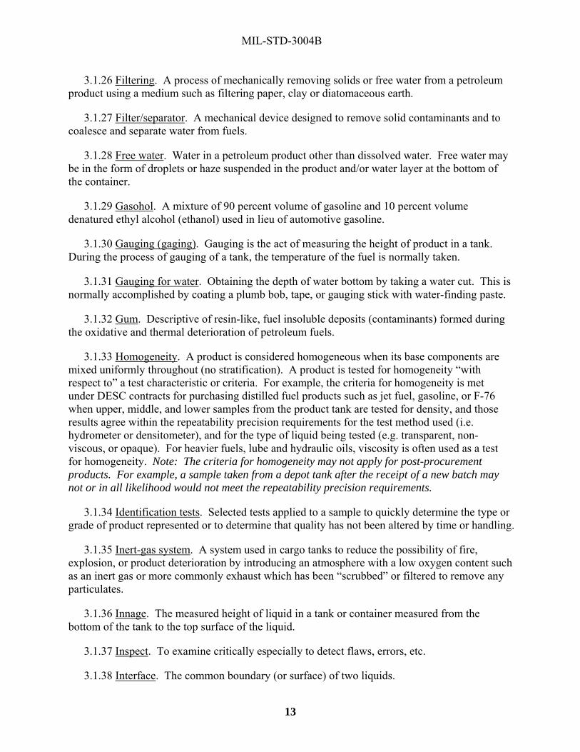
3.1.26 Filtering. A process of mechanically removing solids or free water from a petroleum product using a medium such as filtering paper, clay or diatomaceous earth.
3.1.27 Filter/separator. A mechanical device designed to remove solid contaminants and to coalesce and separate water from fuels.
3.1.28 Free water. Water in a petroleum product other than dissolved water. Free water may be in the form of droplets or haze suspended in the product and/or water layer at the bottom of the container.
3.1.29 Gasohol. A mixture of 90 percent volume of gasoline and 10 percent volume denatured ethyl alcohol (ethanol) used in lieu of automotive gasoline.
3.1.30 Gauging (gaging). Gauging is the act of measuring the height of product in a tank. During the process of gauging of a tank, the temperature of the fuel is normally taken.
3.1.31 Gauging for water. Obtaining the depth of water bottom by taking a water cut. This is normally accomplished by coating a plumb bob, tape, or gauging stick with water-finding paste.
3.1.32 Gum. Descriptive of resin-like, fuel insoluble deposits (contaminants) formed during the oxidative and thermal deterioration of petroleum fuels.
3.1.33 Homogeneity. A product is considered homogeneous when its base components are mixed uniformly throughout (no stratification). A product is tested for homogeneity “with respect to” a test characteristic or criteria. For example, the criteria for homogeneity is met under DESC contracts for purchasing distilled fuel products such as jet fuel, gasoline, or F-76 when upper, middle, and lower samples from the product tank are tested for density, and those results agree within the repeatability precision requirements for the test method used (i.e. hydrometer or densitometer), and for the type of liquid being tested (e.g. transparent, non-viscous, or opaque). For heavier fuels, lube and hydraulic oils, viscosity is often used as a test for homogeneity. Note: The criteria for homogeneity may not apply for post-procurement products. For example, a sample taken from a depot tank after the receipt of a new batch may not or in all likelihood would not meet the repeatability precision requirements.
3.1.34 Identification tests. Selected tests applied to a sample to quickly determine the type or grade of product represented or to determine that quality has not been altered by time or handling.
3.1.35 Inert-gas system. A system used in cargo tanks to reduce the possibility of fire, explosion, or product deterioration by introducing an atmosphere with a low oxygen content such as an inert gas or more commonly exhaust which has been “scrubbed” or filtered to remove any particulates.
3.1.36 Innage. The measured height of liquid in a tank or container measured from the bottom of the tank to the top surface of the liquid.
3.1.37 Inspect. To examine critically especially to detect flaws, errors, etc.
3.1.38 Interface. The common boundary (or surface) of two liquids.

MIL-STD-3004B
14
3.1.39 Intra-Governmental receipt limit. The extent that properties of DoD-owned petroleum products may change beyond specification requirements and remain acceptable for receipt and issue within the DOD logistic system.
3.1.40 Light-ends. The lower-boiling fractions of a fuel or oil.
3.1.41 Lubricity. Ability of a fluid to reduce the friction between two surfaces in motion. In fuels, it refers to a value tht is measured by a scuff load BOCLE test, or the high frequency reciprocating rig (HFRR) test.
3.1.42 Marine gasoil. A distillate fuel, containing no residuals, used for vessel propulsion.
3.1.43 Material Inspection and Receiving Report (DD Form 250/250-1). Government document identifying the contractor, product origin, product type, quality, quantity, and the destination of the product. The DD Form 250 document is signed by the Government Representative (QAR) and the DD Form 250-1 (waterborne movement) is signed not only by the Government Representative, but also by a refinery/facility representative along with a vessel representative. NOTE: For bunkers, a completed commercial report and/or order form should be used instead of the DD Form 250, for which the Government clearly annotate quantity of fuel received, then sign and date the form.
3.1.44 Micron. One micron (micrometer, 10-6 meter) is one-thousandth part of one millimeter (approximately 25,400 microns equal one inch). The average human hair is about 100 microns in diameter. The openings in a 100-mesh screen are 150 microns.
3.1.45 Mineral oil. Lubricating oils from petroleum sources with or without additives.
3.1.46 Off-specification product. A product which fails to meet one or more of the physical, chemical, or performance requirements of the specification.
3.1.47 Outage (or ullage). This is the linear distance between the top surface of the liquid in a drum, tank or tank car and the top of the container (or ullage may refer to available fill volume of the tank and is the difference between the full (rated) capacity and the actual contents of a storage container). In some tanks and tank cars, it is the difference between a reference mark and the surface of the liquid. It is important that some appreciable difference always exist in order to allow a free space for the expansion of the contents in case of a rise in temperature. Quantity in ships’ tanks is normally determined by outage (ullage) gauges.
3.1.48 Oxygenated fuel. A fuel containing molecular species that include oxygen (for example, alcohols, ethers) and is miscible with conventional hydrocarbon fuels. Oxygenated fuels generally show lower heating values than that of hydrocarbon fuels.
3.1.49 Packaged product. Petroleum products stored, transported and issued in containers of 55 gallons or 400 pound capacity or less and also include the 500-gallon collapsible drum.
3.1.50 Pipeline batch. The quantity of a product pumped into the pipeline in one continuous operation.
MIL-STD-3004B
15
3.1.51 Pipeline tender. A quantity of the product offered or designated for pipeline shipment. It may be moved in one or more batches.
3.1.52 Product Equilibrium. In a storage tank after receipt of product, the product achievers equilibrium when all residual movement has ceased. A tank must be at equilibrium to be ready for final gauging or measurement after receipt.
3.1.53 Quality. The composite of materiel attributes including performance, features and characteristics of a product, or service to satisfy a given need.
3.1.54 Quality assurance. A planned and systematic pattern of all actions necessary to give confidence that adequate technical requirements are established; products and services conform to established technical requirements; and satisfactory performance is achieved. (The generic quality assurance definition includes all actions beginning in the design phase through procurement, storage and handling, transportation and use.) “For the Government, Contract Quality Assurance is a method to determine if supplier of product and /or services fulfilled its contract obligations pertaining to products and/or services provided. It includes all actions required to ensure the Government is receiving the proper products and/or services. By common usage, Petroleum Quality Assurance responsibility is fulfilled when the product and/or service is accepted by the Government and the product no longer belongs to the contractor or when the service is complete.”
3.1.55 Quality Assurance Representative (QAR). An organizational title assigned to the individual responsible for Government contract quality assurance function. QARs have cognizance over the procurement of product or services at contractor facilities such as refineries, terminals, packaging plants, laboratories, and into-plane sites. DESC QARs perform both QA and QS functions. The Military Services may use other organizational titles for personnel performing QA and QS functions.
3.1.56 Quality status listing. A listing containing shelf-life information to determine if Type II (extendible) shelf-life material may continue to be used.
3.1.57 Quality surveillance. The aggregate of measures (blending, stock rotation, sampling, etc.) used to determine and maintain the quality of product receipts, storage of products, and issuing of product to the degree necessary to ensure that such products are suitable for their intended use.
3.1.58 Quality surveillance program. Program of inspections, sampling, testing, and documentation established to assure quality of Government-owned product.
3.1.59 Quality Surveillance Representative (QSR). The Government representative responsible for assuring contractor compliance to the requirements of petroleum service contracts or pipeline tariff/operating agreements. The QSR serves at storage terminals (contractor-owned/contractor operated, and Government owned/contractor operated), commercial testing laboratories, pipeline terminals, and any place operations occur involving Government-owned petroleum products. Since DESC’s assumption of the Contract Quality

MIL-STD-3004B
16
Assurance function, DESC has discontinued the use of the QSR designation within its workforce. The Services may refer to them as QSRs or under a different nomenclature.
3.1.60 Reclamation. The procedure that restore or change the quality of a contaminated or off-specification product so it meet the specification of the original product or a lower grade product. The process of reclamation, when properly applied, result in downgrading, blending, purification, or dehydration.
3.1.61 Relative density. The ratio of the mass of a given volume of liquid at a standard temperature to the mass of an equal volume of pure water at a standard temperature. When reporting results, explicitly state the standard reference temperature (examples: Density at 15 °C/15 ºC; Relative Density at 60 °F/60 ºF; API Gravity at 60F/60F, or Relative Density at 20 °C/20 ºC).
3.1.62 Repeatability. Allowable differences in test result values on the same sample by the same operator under the same test condition, with the same equipment.
3.1.63 Reproducibility. Allowable difference in test result values on the same sample by different technicians, laboratories, or equipment under the same test condition.
3.1.64 Requiring installation. A military installation, organization, or facility authorized to requisition and receive material from designated distribution and storage points.
3.1.65 Sample. A sample is a portion of fuel taken which represents that entire batch or delivery. For Bulk Products, a sample can be taken from an acceptance tank, storage tank, delivery truck, intermodal container, pipeline, barge or tanker. Samples may be taken either manually (upper, middle, lower, all-level) or automatically (line, flow-proportionate). For DESC contracts samples are taken in accordance with API Manual of Petroleum Measurement Standards (MPMS), Chapter 8, Section 1, Sampling of Petroleum and Petroleum Products (ASTM D 4057) and/or Automatic Sampling of Petroleum and Petroleum Products (ASTM D 4177). Samples are appropriately identified by sample tag noting location, product, tank number, type of sample/sampler, and date (see continuous sample). For packaged products a sample(s) may be taken from a drum or can using a tube or thief sampler. Sampling may also be accomplished by selecting an individual unit(s) from a collection of packaged products.
3.1.66 Sample Tag. The standard sample tag for petroleum and lubricant Samples is DD Form 2927, Petroleum and Lubricants Sample Identification Tag.
3.1.67 Settling time. The elapsed time a product remains undisturbed or un-agitated in a storage tank to reduce the static charge of the fuel or to allow water and sediment to be eliminated/reduced from the product.
3.1.68 Shelf life. The length of time a product or chemical can typically be stored from the date of manufacture without deteriorating.
3.1.68.1 Type I shelf life. A definite non-extendable period of shelf life.

MIL-STD-3004B
17
3.1.68.2 Type II shelf life. An assigned shelf-life period that may be extended after completion of inspection, testing, or restorative action.
3.1.69 Rehabilitation. To restore or return to specification requirements.
3.1.70 Specification. A detailed description of the product’s essential performance and/or physical and chemical characteristics. Specifications can be classified as Federal, Military, Commercial, or Voluntary Standard. Specifications can be categorized as functional, design, or a performance specification. Some specifications, such as petroleum, are usually a combination of functional and performance.
3.1.71 Specification limits. The extent that properties of non-DoD owned petroleum products may deteriorate prior to receipt by a DoD agency. Note: These are the minimum limits that can be accepted from a supplier to a DoD activity.
3.1.72 Specific gravity. See relative density.
3.1.73 Storage tank. A large container used for liquid (fluid) storage.
3.1.74 Super-clean fluid. A fluid having a specified particulate contamination limit that is so low that the product is packaged in hermetically sealed containers under clean room conditions.
3.1.75 Surfactant. Any substance, which when dissolved in water or aqueous solution, reduces its surface tension or the interfacing tension between it and another liquid. Also called a surface-active agent. Tends to block removal of entrained water in fuels.
3.1.76 Synthetic oil. A materiel not refined from petroleum sources, but generally produced by chemical synthesis.
3.1.77 Testing. The determination of product physical and chemical properties. Depending on the location, mode of storage, and transportation (see Table IX) the following type tests are defined:
3.1.77.1 Type A Tests. Complete quality conformance specification acceptance tests.
3.1.77.2 Type B-1 Tests. Partial analysis comprising the checking of principal characteristics most likely to have been affected in the course of moving the product.
3.1.77.3 Type B-2 Tests. Partial analysis to verify characteristics susceptible to deterioration because of age.
3.1.77.4 Type B-3 Tests. Partial analysis for contamination; in particular, for controlling the re-injection of pipeline interface products.
3.1.77.5 Type C Tests. Quick, simple, partial analysis for verification of product quality, ensuring that no change has taken place. Type C tests sometimes are referred to as identification tests.

MIL-STD-3004B
18
3.1.77.6 Verification Tests. The testing performed by the supplier on a sample (s) verified (witnessed) by the QAR after the supplier has completed full specification testing and certified each shipping tank(s) as ready for acceptance. The scope of the testing is the minimum required to verify that the results presented by the supplier on his full spec test report in fact reflect the product being offered.
3.1.78 Thief. A sampling apparatus designed so a liquid sample can be obtained from any specified point in the container.
3.1.79 Tolerance. An allowable variation from a specified standard.
3.1.80 Ullage. See outage.
3.1.81 Vapor pressure. The measure of pressure exerted by a product on the interior of a special container under specified test conditions because of its tendency to vaporize.
3.1.82 Volatile alkyl lead antiknock. Volatile alkyl lead compounds (for example, tetramethyl lead and tetraethyl lead) which, when added in small proportions to gasoline, increase the octane rating.
3.2 Acronyms and Abbreviations.
3.2.1 AGMA - American Grease Manufacturers Association
3.2.2 AKI - Anti-Knock Index
3.2.3 AO - Anti-Oxidant additive
3.2.4 API - American Petroleum Institute
3.2.5 ASTM - ASTM International
3.2.6 BBL - Barrel
3.2.7 BOCLE - Ball On Cylinder Lubricity Evaluator
3.2.8 CEPS - Central European Pipeline System
3.2.9 CI/LI - Corrosion Inhibitor /Lubricity Improver additive
3.2.10 COCO - Contractor-Owned, Contractor-Operated
3.2.11 CU - Conductivity Unit
3.2.12 DCMA - Defense Contract Management Agency
3.2.13 DESC - Defense Energy Support Center
3.2.14 DFAMS - Defense Fuel Automated Management System

MIL-STD-3004B
19
3.2.15 DFARS - Defense Federal Acquisition Regulations
3.2.16 DLIS - Defense Logistics Information Service
3.2.17 DoD - Department of Defense
3.2.18 DoDSSP - Department of Defense Single Stock Point
3.2.19 DRMO - Defense Reutilization and Marketing Office
3.2.20 DSCR - Defense Supply Center, Richmond
3.2.21 EA – Executive Agency
3.2.22 FAR - Federal Acquisition Regulations
3.2.23 FSC - Federal Supply Class
3.2.24 FSII - Fuel System Icing Inhibitor
3.2.25 FAS - Fuels Automated System
3.2.26 GOCO - Government-Owned, Contractor-Operated
3.2.27 IFO - Intermediate Fuel Oil
3.2.28 JPO - Joint Petroleum Office
3.2.29 JPTS - Jet Propulsion, Thermally Stable
3.2.30 MDA - Metal Deactivator Additive
3.2.31 MGO - Marine Gas Oil
3.2.32 MMR - Motor Mid-grade, Reformulated (unleaded) gasoline
3.2.33 MPR - Motor Premium, Reformulated (unleaded) gasoline
3.2.34 MRR - Motor Regular, Reformulated (unleaded gasoline)
3.2.35 MSC - Military Sealift Command
3.2.36 MSEP - Microseparometer
3.2.37 MUM - Motor Unleaded, Mid-grade gasoline
3.2.38 MUP - Motor Unleaded, Premium gasoline
3.2.39 MUR - Motor Unleaded, Regular gasoline

MIL-STD-3004B
20
3.2.40 NATO - North Atlantic Treaty Organization
3.2.41 NSN - National Stock Number
3.2.42 POL - Petroleum Oils and Lubricants
3.2.43 PORTS - Paperless Ordering & Receipt Transaction Screen
3.2.44 ppm - Parts Per Million
3.2.45 psi - Pounds per Square Inch
3.2.46 PC&S - Post, Camps and Stations
3.2.47 QAR - Quality Assurance Representative
3.2.48 QAS - Quality Assurance Specialist
3.2.49 QS - Quality Surveillance
3.2.50 QSR - Quality Surveillance Representative
3.2.51 RVP - Reid Vapor Pressure
3.2.52 SDA - Static Dissipater Additive
3.2.53 STANAG - Standardization Agreement (a NATO document)
3.2.54 VP- Vapor Pressure
3.2.55 WSIM - Water Separation Index, Modified

MIL-STD-3004B
21
4. GENERAL REQUIREMENTS 4.1 Personnel competency. Personnel responsible for handling fuels and lubricants be thoroughly trained and fully qualified to perform their assigned responsibilities. They be aware of the hazards in handling fuels and lubricants, as well as the applicable safety and operating procedures. 4.2 Service/contractor responsibilities. The owning Service/Contracted activity have the responsibility of maintaining quality and quantity of Defense Working Capital Fund products while in their keeping (e.g.: receiving, storing, sampling, testing, releasing) and dispense those products as required to using activities. The Service/Contracted activity develop, establish and maintain a quality surveillance program IAW this Standard for Defense Working Capital Fund products from the point of receipt on the installation to the point of sale. The program be in accordance with this Standard and be in effect from receipt to end-item issue. Quality problems involving Defense Working Capital Fund product (e.g.: off-spec product, downgrading of product, etc.) be addressed as outlined in this Standard. Adequate sampling and testing programs can reduce or in some cases eliminate quality problems. 4.2.1 Sampling. All samples be taken in accordance with ANSI Z1.4, API MPMS, Chapter 8, Section 1, Manual Sampling of Petroleum and Petroleum Products (ASTM D 4057), and Section 2, Automatic Sampling of Petroleum and Petroleum Products (ASTM D 4177), and/or as prescribed by product specification or contract requirements. For Aerospace Energy Commodities (e.g. gases, cryogenics, liquid propellant and hypergols) refer to the appropriate product specification to determine appropriate sampling methods and procedures. 4.2.1.1 Precautions. The precautions required to ensure representative sampling are many and depend on type of product being sampled, the type of container from which it is drawn and the sampling procedures employed. Each procedure is suitable for sampling a specific product under definite storage, transportation and container conditions. 4.2.1.2 Personnel conducting sampling. Because improperly taken samples can completely invalidate a test, only trained and experienced personnel be assigned to sample the products. This cannot be overstressed: No amount of laboratory work give reliable data on a product if the sample is not a true representation of that product. 4.2.1.3 Responsibility. This Standard in no way alter any assigned responsibility of the various activities outside the continental United States for submitting special samples to a designated laboratory or as directed by cognizant headquarters. 4.2.1.4 Types of samples. A sample is a portion of fuel taken which represents that entire batch or delivery or a specific spot within a tank or container. The various types of samples follow: 4.2.1.4.1 All level sample. One taken by submerging a stoppered beaker or bottle to a point as near as possible to the draw off level, then opening the sampler and raising it at such a rate that it is about 75 percent full as it emerges from the liquid.

MIL-STD-3004B
22
4.2.1.4.2 Upper sample. One taken from the middle of the upper third of the tank contents. 4.2.1.4.3 Middle sample. One taken at the middle height of the tank contents. 4.2.1.4.4 Lower sample. One taken at the middle point of the lower third of the tank contents. 4.2.1.4.5 Top sample. One taken six inches below the top surface of the tank contents. 4.2.1.4.6 Drain sample. One taken from the draw off or discharge valve. 4.2.1.4.7 Bottom sample. One taken on the bottom surface of the tank, container, or pipeline at its lowest point. The drain and bottom samples are usually obtained to check for water, sludge, scale, or other contaminants. 4.2.1.4.8 Single tank composite sample. A blend of the upper, middle, and lower samples of the tank contents. The portion of the sample quantity to be taken at each level varies according to the type of tank and be determined by applicable procedure (see 4.2.1). 4.2.1.4.9 Conveyance composite sample. A blend of individual all-level samples from each compartment of the ship, barge, or carrier that contains the same grade of product in proportion to the volume of product in each compartment. 4.2.1.4.10 Outlet (suction) sample. One taken at the level of the tank outlet. 4.2.1.4.11 Automatic sample. A sample taken from a pipeline conveying the product in such a manner as to give a representative average of the stream throughout the period of transit. 4.2.1.4.12 Mixed sample. One obtained by mixing or vigorously stirring the contents of the original container and then pouring out or drawing off the quantity desired. 4.2.1.4.13 Tube or thief sample. One taken with a sampling tube or special thief, either as a core or spot sample from a specified point in the container. 4.2.1.4.14 Batch/lot samples. One obtained from a collection of units of packaged products. 4.2.1.5 Taking of samples. A sample log should be maintained for all samples taken. 4.2.1.5.1 Sampling apparatus, containers, and procedures. Warning! All safety instructions be strictly observed.

MIL-STD-3004B
23
a. Approved type sample containers be used as specified by ASTM, API, Department of Transportation or International Civil Aviation Organization. Samples of aviation fuel submitted specifically for water and sediment determinations always be collected in clear glass bottles and protected from exposure to sunlight. Aviation sample containers used for samples taken for thermal stability, water separation index tests conform to ASTM D4306, b. All sampling apparatus and containers be thoroughly clean and dry and special care be taken so that no lint or fibrous material remains in or on them. Unless otherwise specified in the test procedures, apparatus and containers be rinsed with a portion of the product being sampled to ensure the sample is not contaminated with the previous material. Coated cans that have been presoaked with a product are preferred when sampling for water reaction and for thermal stability. If not available, then clear or amber gallon glass jugs work very well. If clear glass containers are used, then they be prepared (e.g.: wrapped in aluminum foil) to prevent light absorption. Sufficient liquid product be in the sample lines and fittings before taking any sample. Sampling apparatus be cleaned immediately after use and stored so it remain clean until next use. c. Unless specifically required for special testing, do not take samples through storage tank clean-out lines, manifolds, water draw-offs, bleeder valves, or hose nozzles. Such samples not be representative of the product in the tank. When it is necessary to sample service station tanks and access to such tanks cannot be gained though a manhole or sampling hatch, the tanks may be sampled through a servicing hose after first discharging from the hose a volume of product estimated at two-times the capacity of the piping system. d. Containers such as drums be sampled with a thief. In sampling drums and cans, care be taken to remove all foreign matter from the area near the enclosure before the plug is removed. e. Immediately after taking samples, close all sample containers tightly. Do not use sealing wax, paraffin, rubber gaskets, pressure sensitive tapes, or similar material to seal containers. Lightweight sample containers be adequately crated to withstand shipment. To prevent leakage caused by thermal expansion of the product, do not fill any sample container above 90% capacity. f. Samples for air shipment of turbine fuels and automotive gasoline be in UN1A1 cans, NSN 8110-01-371-8315 (1-gallon), with 4G fiberboard boxes, NSN 8110-01-436-7340 (drum and box combination). The round sample can, NSN 8115-01-192-0935, is suitable for ground shipment of fuels products, via United Parcel Service (UPS). 4.2.1.5.2 Sample Log Requirements. Each activity maintain a sample log containing as a minimum the following information: a. Sample number b. Location sample taken (e.g. tank number, truck number, filter-separator number, etc.)

MIL-STD-3004B
24
c. Type sample d. Date sample taken e. Name of person taking sample f. Reason sample taken g. Product and Grade h. Specification (include approved waiver limits, if known) i. Volume sample represents j. Type tests requested k. Date sample sent to the laboratory l. Date results received back from the laboratory m. Laboratory Report number n. Laboratory Status results (e.g. on-specification, within IGRL, off-specification for XXX test) 4.2.1.6 Precautions. a. Samples of gasoline, jet fuel and kerosene be well protected from contamination and direct sunlight by using clean, dry cans or brown bottles for leaded product. Some of these products, especially gasoline, change color rapidly on short exposure to sunlight and result in rapid increase in gum and decrease in stability. Lead additives, such as tetraethyl lead, are particularly unstable in sunlight and may appear as a gray or gray-white precipitate on the bottom of a container. If clear glass bottles are the only containers available for sampling product containing lead, the bottles be covered with foil or paper immediately after filling to avoid exposure to sunlight. b. Samples of gasoline and jet fuel that require the vapor pressure test be carefully handled and collected to preclude the loss of light-ends. Vapor pressures are extremely sensitive to evaporation losses and to slight changes in composition. When obtaining, storing, or handling samples, observe the necessary precautions to ensure samples are representative of the product and satisfactory for vapor pressure tests. Whenever practicable, arrangements should be made to maintain liquid fuel samples at a temperature between minus 1° C and 4° C (30° F and 40° F). This help preserve its characteristics from the point of sampling to the laboratory.

MIL-STD-3004B
25
c. If the API gravities of fuel samples taken from the upper, middle and lower levels of a tank do not differ by more than the reproducibility precision statement of the test method used for the type of liquid in question, then make a composite of these samples for additional testing. If the variation is greater, test the samples separately because the fuel may have stratified. In this case, each of the various stratified layers be tested independently for conformance to the product specification. 4.2.1.7 Size of samples. 4.2.1.7.1 Normal sample size. Normally, liquid samples submitted for type A or B analysis not be less than 4L (one-gallon) total size; semisolids not be less than 2.25kg (five pounds). 4.2.1.7.2 Special sample size. Special samples and gasoline samples requiring ASTM D909 aviation supercharge method of determining performance numbers be of 20L (five gallons) size unless otherwise directed. 4.2.1.7.3 Jet fuel. Samples of jet fuel requiring full specification testing be 8L (two gallons), 4L (one gallon) of which be used for the filtration time/particulate contamination test. 4.2.1.8 Identification of samples. Immediately after sampling, identify each sample container by securely attaching a DD Form 2927, Petroleum and Lubricants Sample Identification Tag. Information on the tag include the location of the facility at which the sample is taken, name of personnel taking the sample, grade of material, quantity represented, specification of material when known, storage tank number and location, date sample was taken, type of sample and reason for sample. For turbine fuel electrical conductivity (in pico Siemens per meter (p/Sm) units) results, specify tank ambient temperature and request correction of conductivity value to that temperature. 4.2.1.8.1 Markings. In the case of packaged products, the complete markings shown on the container be furnished. The container from which the sample was taken be marked with the sample number for future identification. 4.2.1.8.2 Sample serial numbers. Each sample be assigned a serial number that be determined by taking the calendar year as the prefix number and assigning consecutive numbers as the samples are submitted. For example: the first sample submitted in 2003 would be 03-1, the second 03-2, and so forth. Such sample numbers be shown on the sample identification tag, all shipping documents and correspondence pertaining to the sample. 4.2.1.8.3 Retained samples. Unless otherwise specifically instructed, samples be retained for 60 days for reference purposes. 4.2.1.9 Shipping samples to a laboratory - Chain of custody requirement. In order to ensure sample integrity a record of the chain of custody must be maintained by the sample owner until sample disposal. Each change of custody be documented at the time and place of transfer including signature of the custodian.

MIL-STD-3004B
26
4.2.1.10 Ullaging and sampling JPTS cargo tanks or vessels at intermediate load/discharge ports. 4.2.1.10.1 Contamination problems. When a partial cargo is to be loaded aboard an arriving vessel, the QAR/QSR be required to sample/ullage all compartments loaded at previous ports. In the case of JPTS this procedure can present a contamination problem. These type fuels require special handling because they are easily contaminated. They are usually the first loaded in a multi-product/multi-port lifting and often the last discharged. 4.2.1.10.2 Unaccountable product loss or gain. Ullaging, sampling and water-cutting of JPTS compartments should not be conducted at intermediate terminals unless it is discharged at the intermediate terminal or there is a clear indication of contamination or an abnormal unaccountable quantity loss/gain. If JPTS compartments are ullaged/sampled, all equipment introduced into the fuel be cleaned and repetitions be minimized. A note be placed on the DD Form 250-1 or accompanying ullage report explaining complete circumstances. 4.2.2 Testing. The quality surveillance segment (testing) presented in this section is the minimum essential to sound management of Government-owned properties. It represents the balance between good QS practices, cost of quality and risks associated, and the need to confirm adherence to specification requirements through full specification testing. Only by thorough testing procedures can premium quality surveillance be maintained. 4.2.2.1 Contamination tests. Suspected contamination of petroleum products be confirmed by laboratory tests. Tests which have proved most useful in determining whether a product is contaminated and the identification of the contaminating agents are listed under the individual products (see section 5.10). 4.2.2.2 Test methods. All laboratory tests be conducted in accordance with the method prescribed in the specification covering the product. However, any special or modified method outlined in this Standard be used in lieu of the specification method when products are evaluated within the scope of this Standard. Specification and intra-Governmental receipt limits are absolute. Multiple tests may be performed and if the results do not differ from each other by more than the amount specified for the repeatability of the method, these results may be averaged to determine compliance with the specification or established intra-Governmental receipt limits. 4.2.2.3 Testing frequency (dormant petroleum products). Table VIII outlines the minimum frequency for testing petroleum and related products by broad category. Since it is the responsibility of the cognizant QAR, petroleum officer, or supply officer to maintain strict quality surveillance, the frequency of testing may be increased as required. Considerations for increased testing are conditions of storage, age of stock and type of product. When a dormant product is tested, a record of the results be maintained to provide a basis for determining product deterioration. Whenever consecutive results indicate possible deterioration, testing frequency be increased. Once the trend definitely reflects deterioration, the report procedures in 5.13.2 be followed. This is especially important for a property such as color that presents no operational problem, but may be an indicator of possible deterioration.

MIL-STD-3004B
27
4.2.2.4 Minimum testing. Table IX outlines the minimum sampling and testing requirements considered necessary for determining the quality of petroleum and related products. It covers the conditions under which a sample is taken, the type of sample and the types of tests required to determine whether the quality is within the acceptable limits. 4.2.2.5 Types of tests required. Tables X through XXII provides a detailed breakdown of the type of tests required for each class of product. These tests are those most likely to reveal contamination/deterioration which may have occurred during product handling or storage. Tables XVII through XXII designate Service and NATO prescribed B-2 tests for specific products. When a product being tested exceeds the specification limits due to contamination, the procedures outlined in Section 5.13.1(Identification of a non-confirming product) or 5.14.4 (Disposition procedures) be initiated. 4.2.2.5.1 Equivalent test. Test methods that provide analogous results and fully correlate with standard ASTM methods, but have not yet been formally accepted by ASTM. These test methods have been found to provide test results that be essentially identical to those results produced by ASTM testing methodologies. 4.2.2.5.2 Predictive testing. The use of instrumental and other types of analytical techniques to predict fuel and lubricant test values using compositional data that typically is determined by standard or wet chemistry methods. 4.2.2.5.3 Alternate test methods. The use of alternate test methods to measure physical properties of fuel is allowed, provided that: the test results are presented in the format required in the specification; the test device has a demonstrated reliability and repeatability equal or better than called for by the ASTM method; and the device has been approved for use by the military services. 4.2.2.6 Testing capabilities. All terminals (commercial and military) receiving bulk products and facilities storing packaged products be equipped and capable of performing tests required by Table IX. When the capability does not exist at the terminal or facility, other laboratories, either commercial or military, may be used. Appendix A lists petroleum testing facilities available to military and commercial users. 4.2.2.7 Calibrating test equipment. All laboratories calibrate testing and measuring equipment to the accuracy necessary to ensure the equipment is within allowable tolerance limits. ISO 10012-1, Part I be used. 4.3 Specifications. Each JPO and petroleum product laboratory maintain an up-to-date file of Government fuel and lubricant specifications (both Military and non-Government specifications and standards). It is not practical to include complete specification limits in this Standard, as specifications are subject to change with variations in product availability and technical developments. Copies of this Standard can be obtained through regular channels from the Department of Defense Single Stock Point (DODSSP), found at the web site:

MIL-STD-3004B
28
http://assist.daps.dla.mil/. Limits cited in this Standard are for Service use of fuel, not for procurement documents. 4.4 Change in grade of fuel. Any change in grade of fuel requires notification to DESC prior to the change. Where product has been found to be off-specification, the DESC Quality Operations Division (DESC-QA) is notified IAW section 5.13.2 of this standard. Disposition instructions may be a change in grade. DESC-QA performs internal coordination with the Inventory Management Division (DESC-FI), Program Budget Division (DESC-RB) and the Inventory & Distribution Division (DESC-BI) within DESC. Disposition instructions are provided by DESC-QA. A change in grade may be requested for other reasons, such as product availability, fuel no longer needed, etc. In these circumstances the activity having physical possession of DWCF fuel request concurrence from DESC-FI. They coordinate acceptability of the change with DESC-QA and determine the inventory impact with DESC-BI before making a decision on acceptance. DESC-FI provides disposition in these cases. 4.5 Government-owned property. Contractors are obligated to adequately protect Government-owned property located on their premises for use on, or in connection with a contract. The periodic inventory and reporting of such property is a contractual requirement. The amount of Government-owned petroleum products in pipelines be reported as a separate item in stock reports. 4.6 Safety precautions. Throughout this Standard there are general safety precautions and instructions that apply to fuel handling and laboratory operations to ensure personal safety/health and the protection of Government property. Occupational Safety and Health Administration, Department of Labor and standard commercial safety practices be observed. 4.7 Measurement, sampling and calibration. For measurement, product sampling and calibration of storage tanks and meters requiring the API Manual of Petroleum Measurement Standards: Chapter 2 covers tank calibration (strapping). Chapter 3 covers tank gauging. Chapter 5 covers measurements by meters. Chapter 7 covers temperature determination. Chapter 8 covers sampling. Chapter 9 covers density determination. Chapter 11 covers volume correction and conversion factors. Chapter 12 covers procedures for calculating the net quantities from the gross measurements. Chapter 17 covers marine measurement. 4.8 Compliance with regulations and laws. Many petroleum products are considered hazardous materials and are regulated as such. Users of this Standard must be aware of regulations and laws governing the products that they are handling. In the event of a conflict between this Standard and a law or regulation, the law or regulation takes precedence.

MIL-STD-3004B
29
5. DETAILED REQUIREMENTS 5.1 Waterborne Operations. This section applies to all movements of product belonging to or to be accepted by the Government. 5.1.1 Shipments by tankers and fleet oilers. This section covers pre-loading and loading procedures for tankers and fleet oilers. Those procedures for barges and refueling craft are covered in 5.1.2. Post loading of tankers and barges is addressed in 5.1.4. 5.1.1.1 MPMS Guidelines. QARs utilize the following guidelines/sections of MPMS Chapter 17, Marine Measurement during the applicable phase of each operation: Section 2 - Measurement of Cargoes On Board Tank Vessels. Section 6 - Determining Fullness of Pipelines Between Vessel and Shore Tanks. Section 8 – Pre-Loading Inspection of Marine Vessel Cargo Tanks. 5.1.1.2 Filtering requirements. Fuel and lubricant deliveries from fleet replenishment vessels be filtered according to filtration standards for the particular product involved, unless these filtration requirements are waived by the receiving ship. Replenishment vessels always take action to remove water from their cargoes. 5.1.1.3 Certifying statements. Statements of quantity and quality accompany all shipments. The DD Form 250-1 is prepared under the supervision of the cognizant Government QAR (or Military Service designated personnel) to cover marine petroleum shipments and receipts of Government inspected products. NOTE: References to the QAR include Military Service personnel designated to perform these functions. 5.1.1.4 Tanker and ocean-going barge inspection policy for MSC vessels. The following applies to vessel cleaning, gas freeing, inspecting and quantity variations between MSC and DESC. It applies only to MSC controlled vessels. Table XXIV is only guidance to be used by QARs for the inspection of MSC vessels. 5.1.1.4.1 Responsibility. Vessel owners/operators are responsible for providing vessels suitable to load and deliver the intended cargo and for determining the need-to-clean vessel cargo tanks. This determination is made by monitoring vessel cargo history and by what cargo is to be loaded. The process for monitoring cargo history and identifying when vessel cargo tanks require cleaning be developed by tanker owners/operators for each vessel. Copies of the DD Form 250-1 and test reports be forwarded to vessels by the loading quality representative should early departure preclude obtaining a copy upon loading completion. 5.1.1.4.2 Required cargo cleaning. MSC vessel cargo tanks be cleaned whenever the following conditions exist (exceptions to these requirements be coordinated with DESC-QA prior to the proposed cargo loading): a. The vessel cargo tanks held ballast between the prior cargo discharge and the scheduled follow-on cargo.

MIL-STD-3004B
30
b. The cargo to be loaded is JP-5, and the previous cargo was other than JP-5. c. The cargo to be loaded is JP-5, JP-8 or JPTS and the previous cargo was F-76. d. The initial loading of a spot or time charter. e. The vessel has been in dry dock, or repairs have been performed on the cargo tanks.
f. The cargo to be loaded is MOGAS and previous cargo was F-76.
g. The cargo to be loaded is other than MOGAS and the previous cargo was MOGAS. 5.1.1.4.3 Internal Tank Inspection requirements. QARs inspect vessels that are loading their first DoD cargo under any MSC charter, or that have not maintained segregated ballast conditions, or that have been dry docked or had repairs made to their cargo system. MSC provide notification to the QAR prior to loading regarding vessels that have been in dry dock or had repairs done to their cargo system. Fleet oilers require inspection of all fuel cargo tanks before initial hire, after shipyard repairs, or after a dry dock session. Inspections for fleet oilers may be made at the shipyard or dry dock when requested. MSC make the request for inspections at the repair facility to the next load port. They may request assistance from a QAR closer to the facility if deemed necessary and acceptable. Any party may request inspection, given proper notification to MSC. When inspection is requested by QARs, the request be forwarded by MSC to the cognizant Region and DESC-QA. This notification be done prior to loading the intended cargo, allowing adequate time for the quality representative to be present for an internal tank inspection. Otherwise, an inspection not be performed. 5.1.1.4.4 Suitability to load. Vessels should arrive at the required port ready to load the intended cargo. Vessels certify that cargo tanks are suitable for loading the intended cargo by including the following statement in the Notice of Readiness: “All compartments, lines and pumps to be used are suitable for loading and delivering the intended cargo.” Vessels also provide the quality representative with soundings of product / water onboard and validated onboard quantities (OBQ) prior to loading. 5.1.1.4.5 Quantity variation. Investigations be conducted by a MSC representative and DESC Quality personnel for variations exceeding the following (shore-to-shore, loading to final destination): 0.2% for cargoes not requiring cleaning, gas-freeing, drop/strip; 0.3% for cargoes requiring drop/strip only; 0.5% for cargoes requiring cleaning, gas-freeing, drop/strip. The Manual of Petroleum Measurement Standard, Chapter 17.5, Guidelines for Cargo Analysis and Reconciliation, be used. 5.1.1.4.6 Responsibility for off-specification cargo. Tanker owner/operators are responsible for off-specification product cargoes when the vessel is identified at fault. The

MIL-STD-3004B
31
Tanker owner /operator be given the opportunity to secure the services of an independent petroleum surveyor in the event a discrepancy would be suspected or identified. A representative sample taken at the custody transfer point be used to determine source of contamination. 5.1.1.5 Pre-loading inspection of tankers and fleet oilers. The following actions be taken prior to approving tankers or fleet oilers for loading: 5.1.1.5.1 Vessel inspection. a. When a vessel internal cargo tank inspection is required (see 5.1.1.3.3 for tanker inspection policy for MSC vessels), the QAR assure vessel conditioning has been performed in accordance with Table XXIV. Before entering vessel tanks the QAR confirm that tanks are vapor free and a fresh air pack is available. Should validation of the confined space condition require the services of a Marine Chemist, it is normally the vessel owner/operator who is responsible for obtaining these services. MSC vessels and charters are not on-hire or back-in-service until the QAR accepts the vessel as suitable to load. b. When a vessel does not require internal cargo tank inspection, the QAR validate that the vessel has either properly cleaned and/or stripped. The QAR validate the vessel certification as required in section 5.1.1.3.4. is written on the Notice of Readiness. The QAR validate the liquid measurements are reflected on the OBQ arrival certificate. The QAR randomly validate the water content in all cargo tanks by witnessing water cuts on the gauge tape. 5.1.1.5.2 Vessel tank inspection. When requested to perform an inspection a QAR personally enter and inspect the vessel’s cargo tanks prior to loading to determine suitability for loading. The QAR also check systems and lines to assure that they are drained and properly isolated and that any overboard discharge, sea suction and isolation valves are sealed and tagged with serially numbered seals provided by the contractor. All seal numbers be recorded on the shipping documents. All cargo valves be in the open position prior to physically entering the cargo tanks. a. In cases of multi-port loadings, the QAR at the initial loading port is responsible for physically inspecting all vessel cargo compartments. Consequently, the QARs at subsequent loading ports not enter any cargo tanks and where possible, empty tanks then be visually inspected from the deck. b. All cargo tanks containing liquids be ullaged and sampled, and samples be retained. Where cargo tanks to be filled have on-board quantity (OBQ) from a previous cargo/parcel, the product previously loaded be ullaged, sampled and tested to the extent deemed necessary for conformance to the applicable specification prior to topping off. Cargo tanks not being topped off (if any) that have been loaded at a previous port be ullaged and sampled. These samples are to be held in the event loading difficulties result in commingling of products. NOTE: This ullaging and sampling does not apply to tanks containing JPTS. Special tank preparations and cargo handling is required for JPTS, to prevent contamination.
MIL-STD-3004B
32
c. Tanks used for loading must be coated with an approved epoxy. Coating must be adherent: no flaking, peeling, or blistering. d. Cargo tanks that contain heating coils be checked to assure that the coils are tight and no liquid/steam can escape from the coils. One way to validate this is by performing a pressure tightness check on the system. Coils containing yellow metals (copper, bronze, etc.) are not permitted for aviation turbine fuel use. The QAR report any vessel found to contain coils with yellow metals to MSC PMO5, DESC Regional Quality Manager and DESC-QA. This preclude chartering that vessel for a cargo of aviation turbine fuel. e. It is mandatory that JPTS be loaded in tanks in which the last product carried was JP-5, JP-4, kerosene, non-aromatic solvent, unleaded gasoline, or arctic diesel. Prior to loading JPTS, tank cleaning requirements are: tanks must be machine washed with hot water, if cleaning chemical and/or salt water is used, the final wash must be with fresh water. Tank bottoms, interior bulk heads and internals must be completely free of sediment, scale and other contaminants. Tanks must be dry and all liquids completely removed from the tanks’ lines after cleaning, must be flushed with fresh water, drained and free of all water. Loading and unloading system must be completely isolated. This be accomplished by completely separate piping systems or by use of blinds. Valves not be depended on to effect isolation. No common lines be used. Steam smothering lines should have at least two valves that can be sealed from the main line to the tanks, or a blind installed that can be readily removed. Each tank have its own individual vent. If ship has a common vent system, tanks used for JPTS must be isolated from balance of the vent system. 5.1.1.5.3 Vessel tank / internal rust test. When considered necessary and where safety precautions permit, the QAR require that samples of the rust be taken from selected cargo tanks and tested with the product to be loaded or with a similar solvent. This procedure is performed to determine the effect upon the corrosiveness and gum characteristics of the product. The rust be pulverized and added to a sample of the product to be loaded, or to a similar product, in proportions of 5 to10 grams of rust per 100 mL of the liquid. After shaking the mixture vigorously for at least one minute, it be filtered free of rust and tested for color, corrosion and residue. 5.1.1.5.4 Vessel loading plans. Loading plans be reviewed to determine their suitability, giving consideration to bulkheads, lines, tank capacities, and ship’s trim. In the case of split cargoes, the QAR ensure the vessel is physically suitable for handling two or more grades of product simultaneously without contamination. The QAR ensure all bulkheads are secure and the vessel has double valve separation or line blanks. If valves are used, such valves be lashed and sealed in proper position against misuse. Initial and normal pumping rates be agreed upon before starting. If differences cannot be resolved locally, they be referred to MSC. Prior to loading, all water be removed from the vessel pipelines and cargo tanks. 5.1.1.5.5 Multi-port inspection. When a vessel is scheduled for a multi-port loading, the inspector at the first loading point inspect, if practical, all of the ship’s cargo tanks to determine their suitability for the scheduled product. The vessel not be approved for loading
MIL-STD-3004B
33
part of the cargo unless all cargo tanks are considered suitable for the respective products. QARs at the subsequent loading point(s) be advised by appropriate means of the results of the previous tank inspections. This does not preclude rejection by QARs at subsequent loading points if conditions warrant such action. 5.1.1.5.6 Quality and quantity determination. Vessel movements not be expedited at the expense of quality and quantity determinations, regardless of pressure or protests. Full support be given the QAR for reasonable actions taken to assure quality and quantity. 5.1.1.5.7 Vessel rejection/delay. For MSC (Military Sealift Command)-controlled vessels, DESC-QA be notified immediately to discuss the reason for rejection and/or need for re-cleaning. The QAR follow up the DESC-QA notification with a report to the cognizant DESC Region, DESC-BI and MSC on vessel rejection or delays in loading operations. The report contain pertinent details, including length of delay anticipated for tank cleaning and product availability. For CONUS locations, telephone MSC Washington, D.C. at 202-685-3121 (FAX: 202-685-5362). All calls be confirmed by a message to Commanding Officer, MSC (COMSC), Washington DC with the local MSC representative and DESC as information addresses. For locations outside CONUS, a priority message be dispatched to COMSC, Washington, DC, with the same information addressed as for CONUS. Rejection or delays be well documented including dates, times, circumstances, personnel, discussion, etc.. They be detailed on the DD Form 250-1 and supporting documentation. Records of these cargoes be kept, as often these cases do not come to trial for years. 5.1.1.6 Pre-loading procedures. 5.1.1.6.1. Assure sampling, testing and approval of shore tank prior to loading aboard the vessel (see Table IX). 5.1.1.6.2. Check loading lines to determine they are properly isolated and do not contain product detrimental to the cargo. Drain free water from each tank to be used through the water draw-off line. 5.1.1.6.3. Assure loading lines are full. In some cases, especially underwater lines, the lines may be required to be empty prior to loading. Witness opening and closing shore tank gauges, and opening and closing meter readings (when used). 5.1.1.6.4. Determine the position and setting of the swing line in the shore tank (where applicable) to prevent loading of any free water or sludge from the tank bottom. Water be drawn from the tank bottom through the water draw-off if it is anticipated that there is any possibility of loading the water with the cargo. 5.1.1.6.5. Review the cargo layout and loading plan. The QAR and the master of the vessel (or his designated representative) concur on the cargo layout and loading plan.

MIL-STD-3004B
34
5.1.1.6.6. Inspection (to include checking the vessel’s log on nature of previous cargoes and the vessel’s condition: leaks, previous rejections and excessive delays, for instance) and approval or rejection of the vessel cargo tanks. 5.1.1.6.7. Assure sea suction and overboard discharge valves are closed and sealed prior to loading. In the case of split cargoes, those valves essential to cargo isolation be sealed with serially numbered seals and their numbers recorded on shipping documents. 5.1.1.6.8. Assure all parties are aware of sampling procedures for “first-in” prior to commencing. Check cargo first-in and line samples’ analyses to verify quality of product moving to the vessel. 5.1.1.7 Loading inspection of tankers and fleet oilers. Product quality and isolation be assured in shore tanks and all lines used in loading. The line fill, approximately 2,000 to 5,000 barrels, first be pumped into one or two cargo tank(s) on the vessel. Request the ship’s officer to switch from this tank to other tank(s) and continue loading. A sample be drawn (after a 30-minute wait) from the first tank and tests performed to determine if the quality of the product being loaded is satisfactory. Further sampling and testing be conducted to the extent deemed necessary by the QAR. If at any time during loading there is an indication of contamination, the loading be stopped until the cause and extent of the contamination has been determined. When loading aviation turbine fuel or kerosene, loading procedures (from COMSCINST 3121.3) be as follows: 5.1.1.7.1 Lines. If the vessel does not have segregated ballast, prior to loading all lines be dropped and water removed from cargo tanks. If simultaneous ballasting or de-ballasting must be performed during cargo operations, record this fact and the reason(s) for it on the Material Inspection and Receiving Report. A description of the degree of segregation that was maintained during the operation should also be recorded. 5.1.1.7.2 Loading rates. Initial loading be at a rate not in excess of three feet / one meter per second (about 1,500 barrels per hour through a 12-inch line) through loading lines into the cargo tanks until the discharge outlet has been covered by at least three feet of the product. Thereafter, the normal loading rate may be resumed. The loading rate of three feet per second applies to the flow into each tank. The total loading rate not exceed the sum of the allowable rates for the individual tanks being filled. If there is evidence of turbulence or splashing of the product in a cargo tank after the discharge outlet is covered by the specified three feet of product, the reduced loading rate be continued until turbulence ceases. 5.1.1.7.3 Thirty minute wait. Ullages, water soundings, temperatures and samples, including the first-in samples, not be taken from any cargo tank until at least 30 minutes after flow into the tank has ceased in order to dissipate static charge built up during the fuel movement. In the meantime, loading of other tanks may proceed. 5.1.2 Shipments by barges and refueling craft. This section covers pre-loading and loading procedures for barges and refueling craft. Those procedures for tankers and fleet oilers are covered in 5.1.1. Post loading procedures for tankers and barges are addressed in 5.1.4.

MIL-STD-3004B
35
5.1.2.1 Pre-loading and loading inspection. Precautions and procedures outlined in 5.1.1.4, 5.1.1.5, 5.1.1.6, and 5.1.1.7 are applicable to barges and refueling craft to the extent possible, except rust samples be taken only if the last cargo carried indicates this action to be necessary and can be taken under safe condition. 5.1.2.2 Product conversions. Table XXV covers conversion from one product to another. 5.1.2.3 Inspection procedures for cargoes. Key operations in loading of barges and refueling craft include the following: 5.1.2.3.1. Sampling, testing, and approving shore contents prior to loading aboard the vessel (see Table IX). 5.1.2.3.2. Checking loading lines to determine that they are properly isolated and do not contain product detrimental to the cargo. 5.1.2.3.3. Ensuring lines are full. Obtaining opening and closing shore tank gauges. Obtaining opening and closing meter readings where necessary. 5.1.2.3.4. Determining the position of the swing line in the shore tank, where applicable, and setting it at a position to prevent loading of any free water or sludge from the tank bottom. Water be drawn from the tank bottom through the water draw-off if it is anticipated that there is any possibility of loading water with the cargo. 5.1.2.3.5. Checking the cargo layout and loading plan. The QAR and the master of the vessel (or his designated representative) concur on the cargo layout and loading plan. The QAR assure that the loading plan is for the ordered quantity. If differences exist between the vessel, shore facility and/or the QAR, the matter must be resolved expeditiously prior to commencement of loading. This may require confirmation from the ordering office. Allowable variances from the ordered quantity per the contract are only acceptable if based on a condition of manufacturing, loading or shipping. Neither product suppliers nor vessels should be targeting more or less than the original ordered quantity. 5.1.2.3.6. Inspecting (to include checking the vessel’s log on nature of previous cargoes and leaks, for instance) and approving or rejecting the vessel and individual cargo tanks. Prior to loading aviation turbine fuels, vessels have the tanks receiving the product stripped and mucked to remove residual contaminants and moisture (IAW MSC Policy 98-01 and Table XXV). These procedures be applied to barges (over 30,000 barrels size) and refueling craft to the maximum extent possible. 5.1.2.3.7. Closing and sealing sea suction and overboard discharge valves prior to loading. In the case of split cargoes, those valves essential to cargo isolation be sealed with serially numbered seals and their numbers recorded on shipping documents.

MIL-STD-3004B
36
5.1.2.3.8. Checking/analyzing first-in and line samples to verify quality of product moving to the vessel. 5.1.2.3.9. Sampling and testing of contents of vessel’s cargo tanks during and after loading (see Table IX). 5.1.3 Receipts from tanker or barge. This section excludes fuels which are delivered directly into a vessel’s fuel tank (the process of bunkering - see 5.5). It also excludes barge receipts under the post camps and station program (see 5.4). For F.O.B. Destination contracts, the product supplier may have a representative present at the discharge facility in order to witness quantity and quality procedures performed at the destination receipt facility. 5.1.3.1 Shore side. Before commencing with a receipt of fuel, personnel assure that the shore-side is ready for discharge to ensure the quality of the product in the receipt tank(s) subsequent to receiving the product. The terminal be aware of the time of the vessel’s arrival. Personnel assure line condition is full and properly isolated in accordance with MPMS. Free water be drained from the tank through the water drawoff line. Shore tanks then be gauged and temperatures determined in accordance with the MPMS. Personnel determine net quantity before discharge. If necessary, samples be taken of the line to assure product is the same as that being discharged (e.g.: when the line contains unlike product in a non-dedicated system or when problems were experienced with the previous receipt). If additives are to be injected into the product during discharge, personnel assure injectors are in working order and that required additives are in proper quantity and quality. 5.1.3.1.1 Returns from Fleet Oilers and USN vessels. Test representative samples sent from the vessel cargo/bunker tanks to assure product quality. In some circumstances the vessel may elect to defuel to a barge to consolidate all product and expedite repairs or operational re-deployment. JP-5 be tested to type B-1 series tests plus thermal stability. F-76 be tested to type B-1 series test. Request disposition instructions for off-specification fuel from DESC-QA IAW section 5.13.2. 5.1.3.2 Vessel pre-discharge inspection. Paperwork onboard the vessel be examined to confirm product type, quantity and quality, and the presence of free water. If there is any indication the product does not conform to the quality requirements, discharge not be commenced until the disposition instructions have been received in accordance with this Standard (see 5.13.2). Personnel verify that seal numbers as compared to the DD Form 250-1 are intact. A meeting be held with vessel personnel prior to discharge to discuss procedures and pumping rates to be used. Tank gauging/temperature determination be witnessed for record and net quantities be calculated. If variations of 0.5% are indicated on an individual barge gauging comprising a shipment of two or more barges, then that barge be discharged separately and separate shore tank gauges taken. Monitor all-level tank samples and testing as stipulated in Table IX, Serials 4a and 4b. Additional testing be performed if required to assure split cargoes have not been commingled. The remainder of the composite sample be retained until discharge is complete and the shore tank is tested. Product is normally discharged when laboratory tests show conformance to specification requirements.

MIL-STD-3004B
37
5.1.3.3 Contaminated product. If the product is suspected of being contaminated, it be sampled prior to off load and submitted to a laboratory for analysis. If testing facilities are not readily available, but a visual examination shows contamination, then DESC be notified (see 5.13.2). Disposition instructions are provided based on the circumstances (product contaminated, contaminant, the configuration of the discharge facility, the urgency for the product) and options available (availability of filter/separators, product isolation ashore, product blending capability ashore, or possibility of product remaining on vessel for disposition at another facility). Prompt action be taken to reduce vessel lay time costs. 5.1.3.4 Discharge. Once authorization for discharge has been given, the vessel notify the shore when ready to commence and ensure communication is maintained between ship and shore for the entire operation. Personnel ensure that line samples are being taken as required (Table IX, Serials 4a and 4b) and monitor logs as well as line sample results. 5.1.3.5 Completion. Upon finishing the discharge, personnel determine product Remaining Onboard (ROB), calculate net quantity received ashore, investigate any quantity discrepancies, sample and test product after settling, complete discharge DD Form 250-1, and gather any other applicable documents to include ullage sheets, bunker reports, etc.. Any delays in discharging and/or investigation results be reported to DESC. a. After the vessel is unloaded, the inspector examine each cargo tank to determine if any product is remaining onboard. Cargo tanks containing product(s) ROB be gauged and the amounts determined by the correct applicable procedures such as capacity tables and wedge formula. If it is impossible to obtain accurate figures, the quantities should be estimated. The quantity, the cargo tank number involved and pertinent information or reason for incomplete discharge be entered on the DD Form 250-1, Tanker/Barge Loading/Discharge Report. If it is not the final destination port, the Government representative at the next discharge port be notified of any unusual conditions, gauges, or losses identified. b. Shipping and handling losses or gains, as cited in DoD 4140.25-M be recorded by the destination Government representative on the DD Form 250-1, indicating the cause of the loss/gain to the extent possible. The destination Government representative remarks concerning the loss or gain be confined to observations and evaluations made at the receiving terminal. Tank gauges, line capacities and ship ullages be checked as necessary in attempting to account for the loss or gain (DoD 4140.25-M along with paragraph 5.1.1.4.6 of this document establishes loss or gain criteria). If the loss or gain cannot be accounted for at the final discharge point, the Government representative immediately communicate with the QAR at the loading point(s) and simultaneously with the Government representatives at each intermediate discharge point (if any) to determine possible reasons for the loss or gain. Each Government representative queried advise final destination of his findings within 15 calendar days. The final destination Government representative consolidate the data and forward it to the accountable property officer. Corrected DD Form 250-1(s) be initiated and distributed as appropriate. c. The required inspection documents consist of DD Form 250-1 (Tanker/Barge Discharge Report), DD Form 250-1 Continuation Sheet, the shore tank ullage or innage report, the vessel ullage or innage report, bunker reports (if any), laboratory test results sheets and such

MIL-STD-3004B
38
other documents as required. Distribution of these documents should be made in accordance with DFARS and/or contractual requirements. d. The foregoing are applicable to fleet oilers and refueling craft to the extent possible at DFSPs. 5.1.3.6 Vessel delay. For MSC-controlled vessels - report to the cognizant DESC Region, DESC-BI and MSC on delays in discharge operations, with pertinent details, including length of delay anticipated. For CONUS locations, telephone MSC Washington, D.C. at 202-685-3121 (FAX: 202-685-5362). All calls be confirmed by message to Commanding Officer, MSC (COMSC), Washington DC with the local MSC representative and DESC as information addresses. For locations outside CONUS, a priority message be dispatched to COMSC, Washington, DC, with the same information addresses as for CONUS. 5.1.4 Post-loading - tankers and barges. This section covers post loading of tankers and barges. Procedures for pre-loading and loading of tankers and fleet oilers are in 5.1.1.6 and 5.1.1.7. Those procedures for barges and refueling craft are covered in 5.1.2.1. 5.1.4.1 Vessel samples. QAR witness sampling of vessel cargo tanks. The QAR monitor cargo tank gauging and temperature determination, and water cuts as time permits. If possible, water be stripped ashore before the tanker is released. Failing this, advise the master to strip water out of the cargo tanks into vessel slop tanks. Maintain surveillance of the stripping operation ashore. Report fuel loss during the stripping operation. 5.1.4.2 Determination of quantity. QAR witness shore tank gauging (opening and closing). The QAR independently determine shore and vessel net quantities, and ship/shore losses or gains. If a ship/shore loss or gain is determined, the QAR re-compute to confirm the numbers and conduct an investigation if there is still a loss or gain and the variance is outside the allowed variance (see 5.1.1.3.5 for tolerances). 5.1.4.3 Inspection documents covering tanker and barge loading. QAR assure completion of the required inspection documents that includes a DD Form 250-1, Tanker/Barge Loading Report, Continuation Sheet, ullage or innage report and such other documents as may be required. If the product is loaded from more than one tank, list the tests applicable to each tank in separate columns headed by the tank number. The date the material in each tank was approved and quantity loaded from each tank be indicated in the appropriate column. The QAR may require additional testing if the situation so warrants. Assure distribution of these documents is made according to DFARS. (NOTE: It is recommended that laboratory tests report sheets be attached separately vice transcribing results onto the DD 250-1.) 5.1.5 Ship-to-Ship Transfers at Sea. Issuing and receiving vessels are responsible for performing quality checks before, during and after a transfer. The issuing vessel strip water from the tank just prior to the transfer to assure water and sediment are not transferred. Line samples be taken and checked for appearance every thirty minutes during the transfer by the receiving vessel.

MIL-STD-3004B
39
5.2 Pipeline operations. 5.2.1 Shipments by pipelines. This section applies to all movements of product belonging to or to be accepted by the Government, except movements of Contractor-owned product where quality is verified after receipt at a terminal and prior to delivery to the Government. The movement of petroleum products via multi-product pipelines presents many problems in the control of quality and the operation requires close surveillance. This section furnishes guidance related to quality of petroleum products shipped in pipelines. 5.2.1.1 Tariffs and agreements. Carriers’ tariffs outline the normal responsibilities of the pipeline company. Supplemental agreements are usually entered into between the Government and the carriers, which further elaborate on the extent of the carriers’ responsibilities. Copies of these agreements be made available to cognizant quality assurance offices by either the DESC Region or prime contractors as applicable. These documents be reviewed by the QARs concerned and the provisions thereof be used in product quality surveillance. 5.2.1.2 Laboratory testing. Fuel be tested in accordance with Table IX and the appropriate Table X-XXII before entry into and after discharge from a pipeline. For pipelines carrying aviation turbine fuels and automotive gasoline, laboratory facilities be made available to perform identification tests on products at terminals along the pipeline system. 5.2.1.3 Markings. Single and multi-product pipelines, pumps, and valves be marked to clearly identify the grade of a product being carried. These markings be placed adjacent to all operating accessories such as valves, pumps, regulators and manifolds. MIL-STD-161 provides guidance on color markings and titles. However, due to security issues, military style markings may be replaced by an acceptable alternative when required by the security office. 5.2.1.4 Identification tests. When products are transferred through a multi-product pipeline, identification tests are required in accordance with Table IX. 5.2.1.5 Multi-product pipelines. Pipelines are to be used wherever possible for one grade of fuel only. However, multi-product pipelines are often used between bulk terminals. 5.2.1.5.1 Product identification. The product entering a multi-product pipeline or discharging from it be identified by a flag or sign on the connections to the multi-product pipeline. 5.2.1.5.2 Pumping time. Pumping normally be continuous until cutoff of product has been made. 5.2.1.5.3 Pipeline transfer velocity. Product velocities in pipelines be maintained to minimize mixing of product. 5.2.1.5.4 Segregation during transfer. Preferred procedures for segregating products during movement are shown in their order, see the following:

MIL-STD-3004B
40
a. Turbulent flow without plugs between products. b. Hydrocarbon plug between products or grades. c. Mechanical plugs (batching balls) between products or grades. d. Disposal of Water-Mixed Product. Provision be made for removal and disposal of mixed product and water. 5.2.1.6 Terminal, depot and base system. 5.2.1.6.1 Product compatibility. Before the pipeline transfer is started, it be determined whether the product in the line (line fill) is the same as the issue/transfer tank product or can be included in the transfer. 5.2.1.6.2 Cleaning of pipelines. Incomplete flushing or cleaning of multi-product pipelines is a potential source of contamination. Pipelines are cleaned using various methods, most of which involve various types of pigs. These create large quantities of scale, sediment and water called pig clouds. Isolation of these pig clouds is required so as to preclude a major contamination of working tanks. The preferred method of receiving a pig cloud is into a truck(s) to capture the largest portion of the cloud. Containment in a small tank is next or into a tank that is already scheduled for cleaning in the next three months. 5.2.1.6.3 Valve and pipeline control. Proper blinding off of connecting lines and correct valve control during transfer minimize the possibilities of pipeline contamination. 5.2.1.7 Cross-country system. 5.2.1.7.1 Turbulent flow. The maintenance of turbulent flow during multi-product movements and a packed line when shipments are static is mandatory to ensure a minimum of transmix. 5.2.1.7.2 Batch cuts and segregation. Both improper batch cuts and product segregation are potential sources of contamination. 5.2.1.7.3 Contaminated pipeline shipment. Rust contamination during pipeline shipments can result from inadequate corrosion inhibition or scraping of the pipeline. 5.2.1.7.4 System isolation. Isolation of the system from all inter-connecting lines by suitable blinds or two block valves with an open bleeder valve between minimize the possibility of product contamination. 5.2.1.8 Common transfer lines and pumps for fuels.
MIL-STD-3004B
41
5.2.1.8.1 Preferred method. It is preferable to utilize separate pipelines, valves and pumps for each type and grade of fuel in order to maintain the quality of liquid fuels. 5.2.1.8.2 Use of water displacement. Except where approved hydraulically-operated water displacement systems are employed, displacement by water is not recommended. 5.2.1.8.3 References. Detailed information on the operation, maintenance and inspection of facilities used in dispensing and storing fuels may be found in appropriate departmental directives and manuals. 5.2.1.9 Segregation. The segregation of product in military multi-product pipelines is accomplished by maintaining turbulent flow or by the use of a batching plug/buffer batch of a suitable hydrocarbon. During movements with turbulent flow, constant surveillance be maintained to ensure minimum flow rates required for turbulent flow in the line are exceeded. Even though commingling occurs under all conditions at the interface between products, the objective is to control the length of the transmix and ensure its proper disposition. The resultant transmix vary in amount with factors like pumping rate, distance and contour of the line, line pressure and number of pumping stations. Cuts into terminal storage be made in accordance with Table XXVI. If this schedule cannot be followed because of operational requirements or limited capacities of a terminal, cuts be made in a manner ensuring delivery of an on-specification product to the consumer. No other product be commingled with grades JP-5, JP-8, JPTS or aviation gasoline (all grades). 5.2.1.10 Corrosion control. Fuels transported by pipeline are subject to contamination by rust, sediment (solids), water and surfactants. Periodic checks be made to determine the extent of internal deterioration of the pipelines. 5.2.1.10.1 Determination of sediment (solids). An increase in solids content in petroleum products while in transit through a system can indicate rust buildup in the system. Particulate buildup may also be the result of insoluble agglomerates formed from fuel oxidation processes. The amount of solids may be determined by ASTM D 2276, D 5452, or D 6217 as applicable. Solids content of product samples taken at the shipping and receiving points or at periodic intervals at the receiving point provide data for comparison. 5.2.1.10.2 Corrosion inhibitors. Fuel for military aircraft and ground vehicles may contain approved corrosion inhibitors to reduce corrosion of the pipeline and handling systems. Corrosion inhibitors also enhance fuel lubricity, which is required for some aircraft components. All aviation turbine fuel normally be supplied by the manufacturer with a corrosion inhibitor. It is permissible to inject approved oil soluble corrosion inhibitors into aviation turbine fuel being moved by pipeline to effectively control pipeline corrosion, subject to the limitation indicated in 5.2.2.10.4. To ensure proper protection, the inhibitor effectiveness be checked at various points along the line. This can be accomplished by a visual inspection of the steel coupons that have been installed in the fuel stream in the pipeline, or by determining metal loss from change in weight of the specimens (see Test Method 1000 of this Standard for rating level). Another method is making a visual inspection of steel rods or strips that have been used in specific laboratory tests on fuels taken from the pipeline.

MIL-STD-3004B
42
5.2.1.10.3 Pressure drop. A gradual reduction in product flow rates while maintaining a constant pumping pressure can be caused by increased internal corrosion in the pipeline system. A continued increase in pumping pressures to maintain normal product delivery rates may also be indicative of internal corrosion buildup. Such evidence be brought to the attention of the responsible authorities. 5.2.1.10.4 Additive concentration. In the event corrosion inhibitor be added, only those inhibitors listed in the current qualified products list for MIL-PRF-25017 and those approved for that product be permitted. Care be taken to ensure approved concentration in the product is not exceeded. Excessive inhibitor lower the water separation rating. Only corrosion inhibitors listed in STANAG 3390, Inspection Standards for Fuel Soluble Corrosion Inhibitors/Lubricity Improvers, are approved for use in the NATO pipeline system. 5.2.1.11 Quality surveillance procedures. QARs should: a. Assure products to be tendered through the pipeline conform to the applicable specification or standard. b. Maintain surveillance over the pipeline operations during the transfer to another carrier and at key points in the system during the movement of tenders. Examine records of pumping rates, progress of tenders, extent of transmix, gravity and color determinations. c. Witness the cutting of tenders or batches into pipeline receiving tanks. In emergency circumstances where witnessing batch cuts is impossible, a review of the product change record be made when the sampling and testing of the receiving tank are witnessed. d. Verify the quality of product in pipeline receiving tankage after receipt of the tender or batch. Select the identification tests to be performed for verification of product quality (See Table IX). e. Maintain familiarity with procedures used to protect or condition the pipeline interiors. f. Where necessary, evaluate the characteristics of the transmix to determine its disposition. The procedures for this evaluation, a suitable form for recording data and a sample of the calculations involved are shown in the product change record form (See Appendix E). 5.2.2 Receipts by pipeline. 5.2.2.1 Before receipt. Before commencing receipt of fuel, personnel assure that the quality of the product in the receipt tank(s) subsequent to receiving the product. The terminal be aware of the time and quantity of the pipeline tender. Personnel assure line condition is full and properly isolated. Tanks then be gauged, temperatures taken and a net quantity determined before receipt of product in accordance with the MPMS or other applicable publication. If necessary, samples be taken of the line to assure product is the same as that being received. If

MIL-STD-3004B
43
product is to be injected during receipt into the tank, personnel assure injectors are in working order and that required additives are the proper type and in the proper quantity and quality. 5.2.2.2 During receipt. To the maximum extent possible, personnel witness batch cuts to assure they are in accordance with contract or operating agreement (e.g.: heart, mid-point, etc.). If line samples are being taken during receipt, assure that each sample is being properly taken. Personnel monitor samples taken throughout the receipt of the tender for contamination (e.g.: water, increased sediment, secondary products). 5.2.2.3 Completion. Upon completion, personnel determine quantity by gauging the receipt tank(s) used, measuring temperatures and calculating net quantity received. Personnel investigate any quantity discrepancy in excess of that cited in DoD4140.25-M and allow receipt tanks time to settle before sampling and testing. Receipt tanks be sampled and tested in accordance with ASTM D4057 (MPMS, Chapter 8.1 or other applicable publication) and Table IX of this Standard. Personnel assure samples are retained as called for in the quality control plan or established quality procedures. DD Form 250 be completed and signed. 5.3 Tank truck/car operations. 5.3.1 Shipments by tank cars and tank trucks. 5.3.1.1 Tank truck service / conversion. Tank cars and tank trucks be continuously kept in the same grade of service to minimize the possibility of contamination. If this is impracticable, each vehicle be processed for a change in grade in accordance with Table XXIII of this Standard, except as outlined in the conversion policy below. 5.3.1.2 Tank truck conversion policy. The following policy is in effect concerning cleaning requirements of commercial tank trucks when switching from gasoline to turbine fuels. Tank trucks are required to be steam cleaned after carrying gasoline and prior to carrying jet fuel. DESC Region Commanders may approve exceptions to this policy for JP-8, provided that the transportation officer can verify that trucks which previously carried turbine fuels are not available and that there is a definite need to forgo cleaning as required by this Standard. This need to forgo the cleaning would be based on having to load out of a specific facility to accomplish a specific mission. (Note: Each facility be a separate request and a separate evaluation. Facilities not be combined in this instance.) The transportation officer then forward a request for exception to the Region Commander, identifying: the need not to clean tank trucks; the risks to product quality; and the procedures to be established to abide by the requirements cited below. A complete file should be kept at the region facility for which an exception has been requested. As a minimum the file should include: identification of the facility, the initial request by the transportation officer, identification of quality controls to be in place; approval or disapproval by the Region Commander, and the collected data. Exceptions for each facility be re-certified by each new commander, transportation officer, and quality manager after initial implementation. All problems with customer rejection of product, or at the facility with off-specification product, be reported to DESC-QA. Exceptions be curtailed any time loss of quality control is indicated. (Note: this policy does not apply to JP-5 and JPTS.)

MIL-STD-3004B
44
5.3.1.2.1 Exception/quality data. As outlined above, the following data should be collected as part of any exception concerning cleaning requirements switching from gasoline to turbine fuels. The following data be collected and requirements met for each DFSP for which an exception is requested: a. The JP-8 received at the DFSP have sufficient headroom difference between the minimum JP-8 specification requirement and actual flash point in the issue tank so that some product degradation can be tolerated. The DFSP issue tank have a minimum 10 oC headroom above the specification or equal to or greater than 48 oC (118 oF). b. DFSP personnel examine each tank truck previously carrying gasoline to determine if the truck to include its pumps and piping have been completely drained and dried. There are no exceptions to a drained and dried truck after it has carried gasoline. c. Test a truck composite for density and flash point prior to release of the truck. DFSPs collect and monitor flash point data. d. Regardless of headroom, only minus 5° C flashpoint degradation be tolerated at the DFSP level. Results beyond this require DFSP personnel to identify the cause of the degradation (e.g., gasoline remaining in the manifold/piping) and discuss with the tank trucking company methods to preclude recurrence. Failure to correct the situation would require the steam cleaning requirement to be reinstated. e. As a precautionary measure, the DFSP submit tank truck composite samples for B-1 plus JFTOT testing every 30 days for the first three months. Barring any problems, samples then be continued quarterly for the first year and then tested as deemed necessary by the QAR. This is a precaution against interactions with new reformulated gasolines, or any possible contamination picked up during transport of JP-8. 5.3.1.3 Tank truck loading. 5.3.1.3.1 Safety. Appropriate safety measures be taken during loading and unloading operations. Blanking caps be fitted to all filling and discharge connections not in use. 5.3.1.3.2 Loading line. Prior to loading, the contents of the source tank and the loading line to the fill rack be checked in accordance with Table IX. 5.3.1.3.3 Procedures at the loading rack. Upon arrival at the loading rack, tank cars or tank trucks be inspected for mechanical condition and suitability to transport the product. Dome covers be opened, bottom outlet caps on tank cars removed, and the bottom outlet valves fully opened. This allow residues from previous cargoes to drain completely into a suitable container. The outlet valves be inspected and if found defective be repaired or replaced prior to loading. 5.3.1.3.4 NATO codes. In NATO countries, wherever possible, the vehicle should be clearly marked with the NATO code numbers of the product being carried.

MIL-STD-3004B
45
5.3.1.3.5 Gaskets and hose connections. Care be taken to ensure gaskets and hose connections are maintained in good condition so fill and discharge connections be air and fluid tight. 5.3.1.3.6 Vehicle tank cleanliness. Each tank car or tank truck be inspected for cleanliness and suitability to receive product. Interiors, including domes, be free from loose rust, scale, or dirt and be dry (water-free) prior to loading. 5.3.1.3.7 Product free-fall. For top-loading facilities, care be taken to prevent fuels other than residuals from free-falling or splashing during loading operations by inserting the discharge hose or loading arm fill pipe to the bottom of the tank. The fill rate be slow until hose or fill pipe is covered by six inches of product. Prior to loading, particular attention be given to the outlet and safety valves to ensure they are properly seated and in operable condition. 5.3.1.3.8 Recording test results. The contents of each tank car and tank truck be sampled for the check tests (Table IX) upon completion of loading. Test results be recorded and retained for one year. Retained samples of the truck/car loading be held until product has been received and tested by the using facility. 5.3.1.3.9 Sealing. Domes and/or unloading valves in the case of tank cars and all openings in the case of tank truck loadings be secured and sealed with serially numbered seals immediately after filling. Serially numbered seals and the API gravity at 60º F or density at 15º C be noted on shipping documents. This is not an optional procedure. 5.3.1.3.10 Placarding. Tank cars and tank trucks be properly placarded, identifying cargo being carried prior to departure from the loading facility. 5.3.2 Tank truck/car receipts. This section excludes tank truck receipts of motor gasolines, diesels and heating oils under the post, camps and station program (see 5.4). 5.3.2.1 Before receipt. Before commencing a tank truck receipt of fuel, personnel assure that the receipt tank is ready and that the quality of the fuel in the receipt tank(s) has been determined subsequent to receiving the product. The terminal/facility be aware of the time and quantity of the arriving tank trucks. Personnel assure line condition is full and properly isolated to receipt tank. Normally, lines are dedicated, however, if not, line condition also be checked. Receipt tank(s) then be gauged, temperatures taken and a net quantity determined in accordance with MPMS or other applicable publication, before fuel receipt. If necessary, samples be taken of the line to assure product is the same as that being received. If product is to be injected with additives while discharging into the tank, personnel assure injectors are in working order and that required additives are the proper type and in proper quantity and quality. 5.3.2.2 Tank truck/car arrival. Personnel check accompanying paperwork to assure the fuel to be unloaded is the proper type and quantity. Validate the product grade in the truck is the same grade as in the receipt tank. Validate that the receiving point is identical to that on the shipping papers. If not redirect the tank truck to the correct off-loading location. If being used,

MIL-STD-3004B
46
truck hoses be checked to assure they are clean and dry for use. Seals, when placed at the load point, be checked to assure they are intact and correspond to the numbers on the shipping manifest/DD Form 250. Afterward, personnel break seals, sample and test each compartment in accordance with Table IX (workmanship). Shipment must be accompanied by the test report for the product carried from the loading point. Provided all conditions mentioned are satisfactory, the product may be discharged into receipt tanks. a. If the required seals are broken or missing, the product not be unloaded until it is determined that the quality and quantity is satisfactory. Demurrage charges, if any, be referred to the cognizant DESC Region. Where tampering is evident, the shipper be notified immediately. b. If water is present, it be drawn off prior to unloading. Fuels which have a cloudy appearance or have an unusual color not be accepted until laboratory tests indicate they are suitable for use. c. At Navy, Marine Corps and Army terminals, personnel compare the density at 15 °C (API Gravity at 60 °F), with the density at 15 °C (API Gravity at 60 °F) reported on the DD Form 250. Both agree within + 2 kg/m3 (0.5 degrees API). d. In the event water has collected in the bottom outlet valve of a tank car and has frozen, preventing the free movement of the valve, a steam jet, hot water or hot cloths may be used for thawing the ice. 5.3.2.3 Tank truck rejection. Before a tank truck is rejected, a receiving organization first notify the origin shipping point and quality representative, identifying the product, truck number and reason for rejection of the product. Activities notify their service control point before rejection. Approval to reject a tank truck be a coordinated decision between the Service Technical Office and DESC-QA. 5.3.2.4 After discharge. Personnel examine tank truck/car to determine if all product has been discharged into receipt tanks. Installation of a VISI-Flow gauge on the receipt system is another method enabling determination of full discharge. When all trucks/cars have been discharged, personnel annotate the receipt quantity on the DD Form 250. Quantity is determined by calibrated meter or gauging receipt tank(s). When tank gauging is the method used for determining receipt quantities, the temperature also be measured and net calculations performed correcting the quantity received to 60 ºF (15 ºC). Personnel investigate any quantity discrepancy in excess of that cited in DoD4140.25-M. Time be allowed for the product to settle in the receipt tank before sampling and testing. Personnel sample and test receipt tanks in accordance with the MPMS, Chapter 8 or other applicable publication and Table IX. Samples be retained as called for in the quality control plan or established quality procedures. 5.4 Receipts of motor gasolines, diesels and heating oils under the post, camps & station (PC&S) purchase program. Under DESC purchase programs, products required at the base level are normally provided under PC&S contracts. The following products are normally procured under PC&S contracts, mostly to non- Government specifications: Fuel oils (FO #2, #4, #6, etc.),
MIL-STD-3004B
47
Gasolines (MUR, MUM, MUP, MMR, MRR, MPR, Gasohol, E-85, etc.), diesel fuels (DF-2, DL-1, DL-2, 1-D, 2-D, No. 1/2/4-D, B20, DS-1, DS-2 etc.) and aviation turbine fuel JP-8 only). Product is usually delivered directly by the contractor, via tank truck or tank wagon to the requiring activity. In some cases barges are used for delivery. On fuels, other than aviation, which are delivered via tank truck or tank wagon to U.S. Government installations for their use and consumption, Government inspection for identity and quantity be performed by the receiving activity in order to accept the fuel on behalf of the Government.. Whenever the item calls for delivery into or by barge, for either origin or destination contracts, the Contractor keep the QAR informed of the loading date and source of supply along with any changes thereto as far in advance of the loading date as is possible to permit necessary inspection by the U.S. Government. The U.S. Government reserves the right to perform quality inspection at all times and places if warranted. 5.4.1 Truck arrival / before delivery. Product may be delivered to one location (by tank truck, fill-to-the-mark or meter) or delivery may be made to several locations (by tank wagon, meter). If unable to take an all-level sample from the truck compartment prior to discharge, then an in-line sample taken after line displacement during discharge may be used. Responsible base personnel examine accompanying paperwork, assuring the correct product, quantity and location. Validate the product grade in the truck is the same grade as in the receipt tank. Validate that the receiving point is identical to that on the shipping papers. If not redirect the tank truck to the correct off-loading location Tank compartments be sampled (all-level) and examined for workmanship. Gasoline, diesel fuel and particularly aviation turbine fuel not contain visible water and sediment. Burner fuels not contain more than a trace of water or sediment. Excessive sediment may plug the burner tip degrading fuel atomization. Water can cause rough burning, corrode the fuel handling system and result in the production of microbiological growth. The type of equipment and type of burner fuel determine the allowable limits of water and sediment in the fuel. If sample testing indicates a problem, product not be accepted. The problem be reported prior to the rejection of the tank truck, through the appropriate service control point, to the DESC contracting officer (PC&S: DESC-PEA (703-767-9509); DESC-PEC (703-767-9520); DESC-PLB (703-767-9536); DESC-PLC (703-767-9511) and DESC-QA (703-767-8362). These are commercial numbers; the DSN is 427-XXXX, using the last four numbers of the phone numbers above. The facsimile number is 703-767-8506 for DESC-BP and 703-767-8747 for DESC-QA. 5.4.1.1 After delivery / before departure. For direct delivery to one location - once off-loading has been completed, the truck be examined to determine if any product is remaining onboard (ROB). This be annotated on the bill of lading. If multiple drops are being made using a meter, the tank wagon also be examined, simply as a check, especially if all quantities are supposed to be delivered. 5.4.2 Barge delivery. Product being delivered by barge be sampled and tested in accordance with Table IX, Serial 4 and the appropriate table (Table X – Table XXII) depending on the type of fuel. 5.5 Receipts from the bunkering program. This section applies to commercial bunker fuels (such as MGO or IFO) from commercial suppliers at ports. The commercial supplier provide

MIL-STD-3004B
48
and maintain an inspection system acceptable to the Government covering supplies under this program. The Government has the right to inspect and/or test supplies called for under this program. Unless otherwise noted, inspection be performed by the receiving activity based on documents required to be supplied by the commercial supplier at the time of delivery. Acceptance of these supplies take place at destination notwithstanding that inspection by the Government may take place elsewhere prior to acceptance. Note that within the DESC Bunkers Program, DESC does not normally perform inspection at source, rather the receiving vessel is expected to perform both inspection and acceptance functions. Acceptance on behalf of the U.S. Government is normally made by the vessel representative. The products provided under the bunker program may either be under DESC contracts or purchased directly by the vessel. The products are delivered to the vessels via barge, pipeline or tank truck when the vessels are moored to the docks. They are delivered to the vessels via barge when they are at anchor. The vessel personnel perform quality and quantity checks. Additional testing of bunker samples may be through a DESC, MSC or vessel contract. Vessels requesting participation in the DESC bunker test program submit their request through Navy/Coast Guard channels to DESC-QA. The requirements for a bunker test program include the following: (1) A flange with a sample valve (sample collar) is required to be on each bunker line to be used for receiving bunkers, (2) A composite sample is taken at the samplepoint, split three ways between the supplier, vessel and testing laboratory, (3) Sample containers/mailers are provided to the vessel for taking and sending a sample to the authorized testing laboratory, (4) Test results are provided back to the vessel within a specified time frame and (5) When problems are encountered during the delivery and cannot be resolved within the limits of the contract, the contracting office be contacted immediately for assistance. 5.5.1 Before bunkering. Validate that the product to be delivered is exactly as ordered. This can be accomplished by taking a sample of the offered product and performing as a minimum type C tests, receiving a certificate of analysis of the product to be tendered, or by validating that the shipping documents indicate the correct product and grade are being delivered. Validate quantity to be received conforms to ordered amount. The vessel has the option to witness manual gauges whether from a shore tank or bunker barge. To prevent fraud, especially on deliveries by bunker barges without delivery meters, the vessel witness the product and water gauges for all tanks aboard the bunker barge. This include all slop and void spaces that could hold cargo. As deliveries are net volume or by weight, assure a temperature is taken from each cargo and slop tank. Confirm with the vessel which tanks be issued to the vessel. When participating in a bunker test program, vessel personnel assure that the sample collar is properly affixed at the manifold, the sample valve is clean, sufficiently cleaned sample containers are on hand to obtain the drip sample and a sufficient number of containers are on hand to make the required distribution of the samples. 5.5.2 During bunkering. If possible, new bunkers should be segregated until test results have been received and indicate that the product is satisfactory for use. Validate at the commencement of the delivery that the product conforms to specification requirements by taking a sample at the flange. Check the appearance and gravity (if capability exists). Save at least two quarts of any product suspected of being off-specification for future analysis. Stop the delivery and investigate when problems develop. Sample several times during the delivery for a visual inspection for water, sediment or other contaminants separate from the in-line composite drip

MIL-STD-3004B
49
sample taken. When participating in a bunker test program, start the composite drip sample as soon as the delivery commences so as to obtain a fully representative sample of the entire bunker delivery. Collect the sample as per instructions provided in the kit. Should sampling indicate a problem on a DESC Bunker contract that can not be resolved locally, discontinue bunkering and notify the DESC-PHB Contracting Officer at (703) 767-8461; or by facsimile to (703) 767-8506. Problems of a quality nature also be reported to DESC-QA directly at (703) 767-8742; or by facsimile to (703) 767-8747. 5.5.3 After bunkering. Validate quantity issued by the supplier and compare vessel receipt figures against supplier issue figures to confirm that any quantity difference is within acceptable tolerances. If manual gauges are used, the vessel has the option of witnessing the after delivery gauges. In order to prevent fraud, witness the after delivery bunker barge water and product gauges from every tank gauged before bunkering commenced. Maintain a record of the before and after bunker barge gauge readings. As deliveries are net volume or by weight, assure a temperature is taken from each cargo and slop tank. Assure all tanks that were not intended for delivery have not received or issued any product, water or slops during the delivery. For vessels participating in a bunker testing program, follow the instructions in the kit on preparing and dividing the sample into aliquots for shipment to the testing facility and retain samples. Normally one aliquot be sent to the laboratory, one signed for by the supplier and one retained on the vessel. If the bunker supplier not accept the sample, annotate in the vessel’s log that the sample was refused and retain the contractor’s sample also. Retains can be put back into a bunker tank after quality results are received and indicate the product conforms to specification requirements. When non-conforming product is indicated, notify the contracting officer providing full documentation on the receipt and the vessel’s desired action for disposition of the non-conforming product. 5.6 Receipts from the into-plane program. DESC contracts are established to service DoD/Federal Civilian aircraft at commercial airports throughout the world. Product is supplied directly to the customer and can be either commercial (Jet A/A-1) or Military (JP-8). Additives such as FSII are provided as per location requirements. Procedures for into-plane servicing are covered under MIL-STD-1548. Problems under Into-Plane contracts be reported to the DESC contracting officer (DESC-PHA/PHB/PHC, 703-767-8488/8495/8476; FAX: 703-767-8506). Problems of a quality nature also be reported directly to DESC-QA (703-767-8738/8743; FAX: 703-767-8747). 5.6.1 AIR card. The AIR Card is used to obtain fuel at commercial locations. It identifies the airplane for billing purposes. Use of the AIR Card does not guarantee fuel quality at locations and contractors not contracted to DESC under the Into-Plane Program. More information on the AIR Card can be found at the following web site: http://www.desc.dla.mil/DCM/DCMPage.asp?pageid=614 5.6.2 Refueling units. When refueling units containing turbine fuel are converted to JP-8, JP-5 or commercial jet fuel service, refer to Table XXIII of this Standard for appropriate guidance. When the type of turbine fuel to be serviced is different from the type in the aircraft tanks, the fuel be serviced at half the normal delivery rate to minimize hazards of static electricity. Kerosene fuel such as Jet A, Jet A-1, JP-8 ,JP-5, and are classified as the same type.

MIL-STD-3004B
50
A different type would be wide-cut fuel, such as JP-4 or Jet B. Supplies of aviation fuel for use in Secured Fuels are sealed and secured in accordance with AFI 31-101, Volume I. 5.7 Receipts of aviation Secured Fuels and support aircraft. Secured fuel is used on any aircraft on which the President of the United States is a passenger. The below procedures apply only to secured fuels. Support aircraft be serviced the same as any other transient aircraft. JP-8 is the primary fuel for use in these aircraft. If JP-8 is not available, alternate fuels (commercial Jet A-1, commercial Jet A or JP-5) may be used. In Table XIII, Support for Secured Fuels, Commercial Jet A-1 include fuels identified by other National Specifications like the Russian GOST specification TS-1 and Chinese specification No. 3 Jet Fuel. Whenever Secured Fuels are used, tests listed in Table XIII (note 1) be conducted on representative samples taken downstream of the final filtration from refueling units or hydrant operating tanks prior to issuing fuel. The sample location be under normal operating pressure and continuous flow. 5.7.1 Refueling on military installations. The Secured Fuels Advance Team contact the Base Fuels Officer and the Air Force Service Control Point to coordinate fuel support and testing. Those tests, within the capability of the base laboratory, be performed on base. Testing beyond the capability of the base laboratory be performed at the area laboratory. If time does not permit testing at the area laboratory, the Service Control Point contact the appropriate DESC Region Quality Manager for guidance in contacting a local laboratory for testing on a service contract basis. Information on laboratories under contract for testing services can be found on the DESC Web page at http://www.desc.dla.mil/DCM/DCMPage.asp?pageid=39 and click on the Contracts List. 5.7.2 Refueling at other locations. The Secured Fuels Advance Team contact the appropriate DESC Region quality manager for fuel support and testing and the AF Service Control Point. The Region Quality Manager assign a Quality Assurance Representative (QAR), who , in conjunction with the Air Force One Advance Team, locate a fuel source and make necessary arrangements for sampling and testing. The QAR contact the Secured Fuels Advance Team with test results in the most expedient manner. 5.7.3 Invoice/acquisition procedures. For testing done at contract locations, a DESC representative validate invoices and send to DFAS-CO for payment. For non-contract locations the invoices go to DESC-RR for validation and then to DFAS-CO for payment. DESC-RRF track “all” expenditures for Secured Fuels laboratory testing. Send invoices to DESC-RRF, 1014 Billy Mitchell Blvd., Bldg 1621, San Antonio, TX 78226-1859. 5.8 Receipt of additives and injection. Product is usually delivered to base level fully-additized. This requires product to have additives injected either at the refinery, GOCO or COCO terminals, before shipment or en-route, such as when product is injected by commercial pipelines just prior to delivery. Finally, product can be injected at the base level, either upon receipt or during a transfer within the facility. In most cases the product to be injected is jet fuel, being injected with FSII, CI/LI, or SDA. The +100 additive is normally injected as part of the base operation into a dedicated refueler. Injection equipment is usually permanently installed, with injectors tapped into the receiving/transfer line, and supplied by a bulk additive tank.

MIL-STD-3004B
51
Responsible base personnel assure injection equipment is in working order and that the rate of injection of the additive into the product is correct. 5.8.1 Receipt of bulk additives. Bulk additives are stored in smaller storage tanks (e.g.: 1,000 - 5,000 USG). Additives are delivered by tank truck (also inter-modal containers for OCONUS) directly from the producer. Upon arrival by tank truck or inter-modal container, paperwork be examined by receiving personnel to assure the proper additive is being received. Because of safety consideration, sampling of additives such as FSII be done with safety equipment and the knowledge of the Material Safety Data Sheet (MSDS). Because of cleanliness considerations, additive sampling equipment not be used to sample other products. Arriving tank trucks be examined to determine if seals are intact. Truck pumps and hoses be clean and capped. Product tank compartments be sampled and tested for workmanship and density to determine if any contamination has occurred. The density of additives must be determined in accordance with product specification. Once accomplished, product may be discharged into the proper storage tank. If unable to take an all-level sample from the truck compartment prior to discharge, then an in-line sample taken during discharge may be used for testing. 5.8.2 During injection. To assure the correct additive concentration, personnel monitor the quantity of additives expended and compare it to the target concentration and to the quantity of product injected. This can be done by comparing the difference in ullage of the additive tank to the quantity of product injected at regular intervals. Even when monitoring equipment exists that provides the injection rate, a manual check be accomplished to assure proper injection rate. This can be accomplished weekly, monthly, etc. depending on the amount of injection being performed and the accuracy of the manual checks. 5.8.3 After injection. Product that has been injected be sampled and tested once receipt/transfer has been completed. Personnel consider outside temperatures, especially for additives such as SDA. Lower temperatures tend to lower SDA readings and higher temperatures tend to raise the readings. 5.9 Bulk storage. Quality surveillance of bulk products begin upon receipt and continue as long as the product is in physical possession of the storage facility. Table IX is referenced for minimum sampling and testing for normal turnaround products and Table VIII outlines frequencies for the testing of products in a static long term storage (see 5.9.1). Sediment and water are the most common types of contaminants found in storage and dispensing systems. Their presence can cause serious problems in the systems, particularly in the operation of aircraft. Positive action be taken to prevent and eliminate their occurrence. 5.9.1 Long-term storage. When product is received into a storage tank and doesn’t have any receipts during a normal turnaround (such as six months), then the product is deemed to be in long-term storage. Product then be monitored for deterioration by requiring B-2 testing to check product stability. Table VIII requires testing every six months for long-term bulk products. This frequency can be maintained as long as deterioration is not detected. However, when deterioration does begin (e.g.: in gasolines when the oxidation stability decreases or gum level increases; in diesel fuel when the particulate contamination increases), the frequency of testing

MIL-STD-3004B
52
be increased, such as from six months to four months. As the deteriorating characteristics approach intra-Governmental receipt limits (see Tables I-VII), product either be consumed on an expedited basis, or rotated so that it can be consumed elsewhere before exceeding the intra-Governmental receipt limits. The rate of deterioration cannot be predicted as storage locations throughout the world differ in temperature and environment, and the products stored are produced differently from refinery to refinery. Therefore, each product in long-term storage be regularly sampled and tested with an increase in testing frequency when deterioration begins. 5.9.2 Bulk tank water restriction. The use of fuel tanks with water bottoms is prohibited unless specifically authorized by the appropriate technical authority. Bulk fuel tanks be drained of water after each product receipt, a minimum of weekly thereafter and prior to each issue. Floating roof tanks be checked more frequently during periods of heavy rain or melting snow. Underground fuel tanks be checked more frequently when the water table is high and during periods of excessive rain or melting snow. 5.9.2.1 Corrosives in tanks. In instances where water bottoms in storage tanks cannot be completely removed the water layer be checked monthly for the presence of hydrogen sulfide. Hydrogen sulfide that sometimes forms as a result of bacterial action on sulfates present in the water (see Test Method 1020 in this Standard) is corrosive and cause the product to fail the copper strip corrosion requirement of the specification. 5.9.2.2 Tank water check frequency. Water checks be made daily on issue tanks and weekly on static tanks or each time a tank is gauged, whichever occurs first. When water is found it be drained as soon as possible. 5.9.2.3 Microbial Contamination. Microbes can exist in extremely small pockets of water. This growth can be corrosive creating pinpoint holes in metal. Microbial growth cycles can result in contamination that clogs filter. A good water removal program is an important maintenance function. 5.9.3 Storage tanks and piping. 5.9.3.1 Storage of similar products. Storage tanks should continue in one type fuel to the extent practicable. The contents of receiving storage tanks always be identified before the receipt of fresh product 5.9.3.2 Changing product in a storage tank. a. When storage tanks are changed from one type of fuel to another, tanks be inspected, cleaned if required and re-inspected to ensure elimination of excessive rust or sludge. See STANAG 3609, Standards for Maintenance of Fixed Aviation Fuel Receipts, Storage and Dispensing Systems, and applicable contract clauses for guidance on this subject. b. Ground diesels may switch between summer and winter grades for cloud and pour point purposes. These changes do not require cleaning/inspection between grade changes. In order to promote the swiftest conversion during from summer to winter grade, the storage tank

MIL-STD-3004B
53
be brought as low as possible before the conversion begins. Product should not be purchased during a summer grade period for storage when the use of the product is primarily for winter use. Careful planning and ordering procedures must be developed to assure the storage tank be prepared for the winter use season. c. Conversion to Ultra-Low Sulfur Diesel (ULSD) Tank. The U.S. Environmental Protection Agency has mandated that diesel fuels contain not more than 15 ppm of sulfur. Many diesel vehicles built after 2007 contain emission control devices that be deactivated by higher levels of sulfur. These devices when overwhelmed with sulfur result in the vehicle shutdown. It is very important that fuel storage tanks be properly converted into ULSD service. The policy for converting a storage tank(s) to ULSD is found at http://www.desc.dla.mil/DCM/DCMPage.asp?PageID=479 under the DESC Policy Document Number DESC-I-15, Conversion of Low Sulfur Diesel Storage to Ultra Low Sulfur Diesel (ULSD). 5.9.3.3 Product cargo check for quality. To the extent practical, cargoes be discharged into a single, low-innage shore tank. After discharging and checking for quality, identical products may be combined in common tankage. Gasoline storage tanks be kept as full as possible to minimize evaporation losses. These losses are excessive in partially filled cone roof tanks during extended storage. The probable need for low innage storage tanks for another product or contaminated cargo be kept in mind. 5.9.3.4 Segregation of product. Grades of product be segregated from one another and whenever feasible all issues made through a segregated system. Segregation of different grades and products be by some positive means such as a blank flange, spectacle plate, spool piece, double valve with open drain, or double block-and-bleed valve. Segregation by a single valve is not sufficient. 5.9.3.5 Leaking valve contamination. To minimize the danger of contamination from leaking valves, one of the following precautions is recommended: a. Use of blank flanges between valves. b. Removal of a section of pipe between two valves. c. Introduction of a bleeder valve (normally open) between two valves. A catch basin (drip pan) be placed under the bleeder valve and monitored on an established schedule to detect leaks. Failure to perform this inspection may result in liquid overflowing the catch basin creating an environmentally unsafe condition. 5.9.3.6 Tank protective treatment. Before an internal protective treatment is applied to any tankage (e.g.: coating), approval from the responsible DESC or service technical authority is required. 5.9.3.7 Identification of piping system. Piping systems be marked to clearly identify the grade of a product being carried. These markings be placed adjacent to all operating

MIL-STD-3004B
54
accessories such as valves, pumps, regulators and manifolds. MIL-STD-161 provides guidance on color markings and titles. In NATO countries the NATO code numbers for the product grade be included in the marking or identification system. (NOTE: In certain situations security requirements may dictate what markings are allowed.) 5.9.3.8 Settling time in tank. Variations apply depending on the settling time is to perform a quantity measurement for official receipt quantities, sampling for tank certification after receipt or permitting the tank’s issue. a. For quantity measurements in tanks greater than 2,000 barrels, a settling time of thirty minutes minimum is required for products that have little to no water (anticipated water level in the tank is less than or equal to one-eighth of an inch). For tanks less than 2,000 barrels allow a minimum settling time of five minutes. For products that retain water and/or sediment (e.g. crude, IFOs, etc), allow a minimum of twenty-four hours of settling in bulk storage tanks before taking a custody transfer measurement upon receipt. Take a provisional gauge after a minimum of thirty minutes of settling noting it as a preliminary gauge for receipt purposes. b. For sampling and issuing functions, the following settling times and issues apply. After stocks have been added, allow maximum possible settling times in order to permit reasonable settlement of waters and solids. A minimum tank settling period of one hour per foot settling is required for tanks greater than 2,000 barrels. For tanks 2,000 barrels, or less, a settling time of thirty minutes minimum is required. This settling period is not necessary when fuel handling system cleanliness has been assured by design to eliminate the ingestion or generation of corrosion products or contaminants and when transfers to the system are made through a properly monitored filter apparatus. c. The settling period does not apply to bulk storage aboard ships. A settling period of thirty minutes aboard ships is recommended for static dispersing. 5.9.4 Control of static electricity (aviation turbine fuels). The following are certain hazards and precautions emphasized in the handling of aviation turbine fuel: a. In filling any empty tank, the initial fuel flow rate not exceed three feet (one meter) per second through a receiving line until the roof of a floating-roof tank is afloat, or a minimum of three feet /one meter above the level of the tank filling line is reached (see 5.1.1.7.2). b. Agitation of the fuel surface and air, and entrainment of air and water in fuel be avoided. c. The fuel stream into storage tanks be horizontal rather than toward the bottom of the tank. d. NFPA 77 states that removal of outer garments is particularly dangerous in work areas where there may be flammable or explosive atmospheres that are ignitable with low electrical energy. Because some materials exhibit static phenomena, especially under low humidity conditions, the outer garments used in these areas be suitable for the work area. Recommend

MIL-STD-3004B
55
that outer garments not be donned or removed where a flammable or explosive atmosphere may exist. e. The sampling device always be bonded to the tank before the sampling hatch is opened. f. Personnel wait a minimum of thirty (30) minutes after receipts of any type of fuel to allow electrostatic charges to dissipate before gauging or sampling. ( see 5.9.3.8 for exceptions for small tanks). g. Other ignition sources of concern are the cell phone and other portable electronic devices (PED). Cell phones or other PEDs should not be used in and around areas where flammable vapors are a risk, unless they have been tested, approved and labeled as intrinsically safe. If at all possible the use of cell phones and other PEDs should be avoided while working in areas exposed to flammable vapors. 5.9.5 Filtration. Filtration equipment of a proper type be a part of some fuel handling systems (see Table XXVIII). The equipment be inspected for condition and performance capability in accordance with applicable standards (i.e.: MIL-PRF-52308, API / IP Specification 1581, etc.) or the equipment’s operations and maintenance manuals. Micronic filtration equipment conform to API/IP Specification 1590. The location of this equipment is to be in accordance with civil engineering design criteria. In commercial installations the requirements for any maintenance of this equipment are to be consistent with the terms of the contract. Because filter/separators generate static electricity their location in the system permit a 30-second relaxation time in product travel between the filtration equipment and receiving containers. The 30-second relaxation time applies only to systems designed for fuel without SDA. Systems designed to deliver fuel with 50 pS/m or greater concentration of SDA need not comply with the 30-second relaxation time. Note: DESC fund all micronic, coalescer and separator filter elements used in fixed-place filtration vessels that service Defense Working Capital Fund fuel. This funding effort not apply to replacement filter elements in non fixed-place filtration elements or other mobile type filtration equipment (e.g., refueling trucks, bowsers, tactical, etc.). Reference DESC homepage (http://www.desc.dla.mil/DCM/DCMPage.asp?pageid=81) at Quality Management/policies. 5.9.6 Internal preservation. If any fuel equipment or facility is likely to be out of service for four months or more, then pumps, fans, motors, etc. be given adequate protection either in place, or by transfer or storage. Tanks be isolated, cleaned, dried and sealed. Water-displacing fluids not be used for the internal protection of aviation fuel tanks, as they are difficult to remove completely and they affect the water reaction property of the fuel. However, such fluids may be used as directed for tanks used for other products. 5.9.7 Dispensing from curbside pumps. The provision for bulk storage tanks are applicable except for conditions outlined in 5.9.2.1. 5.9.8 Deterioration of a product. Characteristics of petroleum products change as the product ages and the change may be accelerated by storage conditions. The degree of

MIL-STD-3004B
56
deterioration can be determined only by laboratory testing, which be accomplished periodically as set forth in Table IX. 5.9.9 Sources of contamination. 5.9.9.1 Inadvertent mixtures. The principle sources of bulk product contamination are: failure to properly identify product in receiving vehicle to proper receipt tank, carelessness in making line connections; error in valve operation during transfer of bulk products; use of contaminated tanks; incomplete cleaning or flushing of product lines; leakage between compartments of a tanker or through partially closed or defective valves. Consequently, every precaution be exercised to prevent the inadvertent mixing of different grades of product as well as contaminating the product with foreign materials like water and sediment. Mixture of products can often be detected by changes in appearance, color, gravity, or odor. Laboratory analysis detect mixtures when not visually detectable. See 5.11 and 5.12 for sources of contamination. 5.9.9.2 Handling personnel. Contamination may also result from accident, inability or failure to follow prescribed procedures, carelessness, or sabotage. Proper identification and strict control of the entire handling and dispensing system be maintained to minimize contamination at bulk storage terminal and user activities. 5.9.9.3 Rubber surface to fuel. Refers to characteristics of elastomeric or rubber compounds that change during exposure to fuel. Seal swelling, an interaction between the fuel media and elastomer materials, is desirable (to a point) as a means to prevent leakage. 5.9.9.4 Container sealant. Fuel containers with bullet hole sealing properties may be particularly hazardous if the fuel should penetrate to the sealing media. Long hose lines not be kept full of product. The initial throughput of a hose system equal to the volume of the hose be checked for excessive contamination. Extra precautions be taken to clean the system or containers if it has been used to store or transport diesel fuel or other lightly inhibited material, such as commercial motor gasolines. 5.9.10 Identification of transfers. Identification be made on all product transfers. Testing be conducted on all product transfers except for transfers of approved stocks from fully segregated systems (pipeline, tank car or truck) and provided that a grade change is not involved. Details of sampling and testing requirements are shown in Table IX. 5.10 Product characteristics / intra-Governmental receipt limits (Tables I-VII). 5.10.1 Gasoline, aviation, NATO F-18 (ASTM D 910/100 LL) 5.10.1.1 Knock rating. The knock value for ratings of 100 or below is stated in terms of octane number and in terms of performance numbers for those above 100.

MIL-STD-3004B
57
5.10.1.2 Color. Aviation gasoline may change color for such reason as mixing with gasolines of another color, contamination, or prolonged exposure to light. A visible cloudy or hazy appearance may accompany the color change. This indicates the presence of suspended water, precipitated lead salts, or other particulate matter. A definite yellow case or darkening of color may be caused by the presence of lubricating oil, diesel fuel, heating oil, or other petroleum products of similar nature. Off-color gasoline not be used until analysis is performed to determine product usage. a. Color standards prepared in 4-ounce bottles from fresh, uncontaminated stocks and compared with the questionable gasoline may provide initial information regarding contamination. b. Confirmation of contamination be obtained from the results of other tests. The type of testing to be performed would depend on the type of contamination suspected, e.g.: commingling, cleanliness, water and sediment. 5.10.1.3 Vapor pressure (VP). Vapor pressures can be tested using various methods. A common test is called the Reid Vapor Pressure (RVP) test measuring the vapor pressure created in a defined volume of air to volume of fuel at 100ºF. a. A VP above 7.0 psi (49 kPa) indicates contamination by a more volatile product. Additional tests and complete investigation of the previous history of the gasoline may identify the contaminating agent. A possible cause of such contamination could be commingling with automotive gasolines which generally have higher VPs. b. A VP below 5.5 psi (38.5 kPa) may indicate weathering (loss of volatile fractions) or commingling with other products having a lower VP. Disposition of a weathered gasoline be made on the basis of other pertinent tests such as distillation range, knock rating, gum and lead content. 5.10.1.4 Corrosion. A gasoline having a copper strip rating of ASTM 2a or greater is corrosive. This may be caused by the presence of other petroleum products or by corrosive materials having been extracted from sulfur-impregnated rust present in transport or storage systems or sulfate reducing bacteria. 5.10.1.5 Water and sediment. These characteristics be controlled within the transportation, storage, handling and servicing systems in order to avoid serious problems in the operation of aircraft and resultant degradation of the supply readiness position. 5.10.2 Aviation turbine fuel, NATO F-34/JP-8 (MIL-DTL-83133), F-35/Jet A-1 (ASTM D 1655) and F-40/JP-4, F-44/JP-5 (MIL-DTL-5624). NOTE: See T.O. 42B1-1-16, Chapter 6, for JPTS (MIL-DTL-25524) test limits. 5.10.2.1 Existent gum. The existent gum not exceed 7.0 mg per 100 mL of fuel and be dry in appearance. The preferred vaporizing medium for aviation turbine fuel is steam, however, the existent gum test (ASTM D 381) may be performed using air as the vaporizing medium with

MIL-STD-3004B
58
the operating temperatures listed in the ASTM test method. However, it must be noted that specification and contract requirements be followed as product and product characteristics may change. 5.10.2.2 Vapor pressure. In requesting disposition for JP-4 which does not meet the VP intra-Governmental receipt limits (see Table I), the recommended alternate use or disposition take into consideration the results of other tests such as the distillation range, existent gum and freezing point. 5.10.2.3 Corrosion. An aviation turbine fuel which has a copper strip corrosion rating of 2a or greater not be used in aircraft. The fuel be segregated and handled in accordance with instructions in 5.13.5. 5.10.2.4 Fuel system icing inhibitor (FSII). One type of FSII is approved for inhibiting ice formation in turbine fuels. Diethylene glycol monomethyl ether (DIEGME) with a flash point of 85 °C (185 °F) has been identified as the type FSII to be purchased for all jet fuels. FSII lowers the freeze point of entrained or free water present in turbine fuels or in fuel systems. The amount of FSII added to turbine fuels in the wholesale system be adjusted to ensure delivery of the fuel with a minimum FSII content of 0.10%, volume, for all grades of turbine fuels. FSII does not readily dissolve into the fuel so it must be dispersed as fine droplets. A proportional-flow injection system is recommended with shearing devices such as meters or mixers downstream of the injector. FSII not fully disperse in “wet fuel” (fuel containing free water) even with proper additive injection equipment. In fuel containing free water, the FSII preferentially solubilize in the water resulting in a lower than expected concentration of FSII in the fuel and water bottoms containing high FSII concentrations. It is recommended a filter-separator system be installed upstream of the FSII injection point if the free water content can not be maintained below 30 ppm during the injection process. The FSII content of turbine fuels be verified when a storage tank is designated as an issue tank or when delivery into the bulk tank. Fuel stored in floating roof issue tanks be checked for FSII content after each heavy rain. Underground storage tanks be checked during periods of heavy rain, melting snow and other periods of high water tables. It should not be allowed to remain in tank bottoms or filter-separator sumps. In FSII treated fuel, the water at tank bottoms and sumps should be carefully drained daily or more frequently if warranted. It is also important to prevent water and moist air from entering the FSII additive tanks because the water dissolves rapidly into the additive. FSII that contains an excessive amount of water not readily disperse into the fuel and can settle in the aircraft fuel tank causing corrosion and deterioration of the tank lining materials. Therefore, a desiccator or other drying mechanism be used in the air vent to prevent entrance of moist air into the FSII storage tank. FSII, either by itself or mixed with water, can be corrosive to epoxy linings or aluminum vessels under certain conditions. Because of its corrosive nature FSII should be stored in stainless steel or Teflon coated tanks. Since laboratory testing has shown long-term stability of FSII is questionable even if stored in stainless steel containers, it is recommended FSII stocks be rotated as frequently as possible, FSII should be checked one month after delivery. FSII stocks should be fully retested for quality conformance every six months as a minimum. Warning: FSII has been determined to be a health hazard. Therefore, special precautions be taken to avoid exposure when handling glycols (for example, while sampling and testing). Refer to the manufacturer’s MSDS for safety precautions.

MIL-STD-3004B
59
5.10.2.5 Flash point specification. JP-5, JP-8, Jet A and Jet A-1 fuel exposed to systems which have recently contained gasoline/naphtha or which have been contaminated by the same is likely to be rendered off-specification for flash point. This is critical non-compliance for JP-5JP-5 because of the safety factors involved in handling fuel aboard vessels at sea. For JP-8JP-8, Jet A and Jet A-1 the flash point non-compliance is a ground handling safety issue. The extent of the severity for aviation turbine fuels used at land-based locations is based on the degree of flash deterioration. 5.10.2.6 Filtration time. Control of this property is essential to prevent rapid differential pressure buildup in filtration equipment and possible migration of finely divided solids into aircraft. Degradation of filterability may occur in transportation and storage systems and is particularly prevalent when fuel is exposed to saltwater and metallic contaminants. 5.10.2.7 Water and sediment. These characteristics be controlled within the transportation, storage, handling and servicing systems in order to avoid serious problems in the operation of aircraft and resultant degradation of the mission readiness position. 5.10.2.8 Conductivity. Conductivity of JP-4, JP-5 or JP-8 is a measure of its electrical conductance. By increasing conductance of the fuel, rapid dissipation of an electrostatic charge can be accomplished. Except for direct deliveries to a using activity from a refiner, the static dissipator additive (conductivity additive) most likely be injected in the JP-4 or JP-8 at the terminal making delivery to the using activity. The conductivity unit (CU) specification requirement for JP-4, JP-5, and JP-8 is 150-600 and 150-450 picosiemens/meter (pS/m) respectively. For JP-8 with the thermal stability improver additive (JP-8+100) the CU limit is 150-700 pS/m. The CU limit for Jet A-1 is 50-600 pS/m. Readings of CUs be taken at ambient temperature or 29 °C (85 °F), whichever is lower. If the sample is tested in a laboratory, results be corrected to the ambient temperature of the tank in accordance with ASTM D 2624. 5.10.2.9 Thermal Stability of JP-5. Most Navy/MSC ships have copper-nickel piping which results in copper leaching into JP-5 that causes Jet Fuel Thermal Oxidation Test (JFTOT) failures. This fuel due to failure of JFTOT is not suitable to be returned to DESC-owned bulk JP-5 stock ashore. Naval Air System Command (NAVAIR) has determined that this product can be burned at sea by shipboard aircraft. Ships carrying JP-5 with non-conforming MIL-DTL- 5624 thermal stability results due to copper contamination (no other known cause) may transfer that JP-5 to other ships for use at sea without DESC’s disposition. 5.10.2.10 Fuel Standardization Policy. The fuel standardization policy (also known as the Single Fuel Policy) mandates the use of a kerosene base fuel as the single fuel on the battlefield, for both aircraft and ground vehicles/equipment. DoD Directive 4140.25 states this policy in great detail. In most cases, this fuel is JP-8.Primary fuel support for sea-based aircraft be a high kerosene-based fuel, JP-5. In overseas theaters where the predominant fuel is in support of the Navy, JP-5 may be substituted for JP-8, as approved by the Combatant Commander, JP-8 and JP-5 have been tested in all types of tactical vehicles and equipment and can be used interchangeably in most cases with diesel fuel. JP-8 when used in tactical equipment

MIL-STD-3004B
60
is currently exempt from the sulfur limits required by the EPA when used in ground vehicle equipment for on-grade use in the United States DoD. 5.10.2.11 Other Aviation Fuel Specifications. Use of Other Aviation Fuel Specifications DESC may obtain aviation turbine fuel conforming to the National specification of another country, if DoD primary fuels (JP-8, JP-5) are not available. All alternate fuel approvals must be processed through the Service Control Points. 5.10.3 Gasoline, automotive,, unleaded (F-67). 5.10.3.1 Octane. Gasolines having an octane or performance number below the intra-Governmental receipt limits, specified in Table VI be re-sampled and the knock rating verified before considering it below the intra-Governmental receipt limits. 5.10.3.2 Color F-67 gasolines are normally clear and bright but may undergo a color change due to mixing with dyed fuels (aviation gasolines, certain commercial leaded gasolines, or high sulfur diesel fuels). A cloudy or hazy appearance that may accompany the color change is usually caused by suspended water or precipitated lead salts or other particulates. A yellow cast may be caused by contamination with diesel fuel, lubricating oil, or other petroleum products. 5.10.3.3 Existent gum. Existent gum not exceed 7.0 mg/100 mL of gasoline (F-67). 5.10.3.4 Lead content. The maximum amount of lead permitted by STANAG 7090, Guide Specification for NATO ground fuels is 0.013 g/L for unleaded gasolines (F-67). Lead content in gasoline may be restricted to a lower limit by local regulation. Lead content be determined by ASTM D 3341 or ASTM D 5059 (Test Method C). 5.10.3.5 Copper Strip Corrosion. Gasoline with a corrosion rating of ASTM 2a or greater be segregated and reported as prescribed in 5.13.5. 5.10.3.6 Vapor Pressure (VP). Vapor pressures are determined by class as well as geographic and climatic conditions. They may also be regulated by national authorities. The following intra-Governmental receipt limits are for guidance only: a. Class 1. Minimum 33 kPa; maximum 72 kPa. b. Class 2. Minimum 43 kPa; maximum 82 kPa. c. Class 3. Minimum 53 kPa; maximum 92 kPa. d. Class 4. Minimum 58 kPa; maximum 97 kPa. e. Class 5. Minimum 68 kPa; maximum 107 kPa.

MIL-STD-3004B
61
5.10.4 Automotive spark ignition engine fuel: commercial gasoline (ASTM D 4814) and gasohol, automotive, unleaded (A-A-52530). Under authority of the Clean Air Act, gasolines marketed in the United States, territories and possessions may have restrictions on vapor pressure limits and have mandates for the use of gasoline-oxygenate blends for the purpose of controlling emission. An oxygenate is a hydrocarbon that contains an oxygen atom embedded in a chain of hydrogen and carbon atoms. Oxygenates are usually alcohols or alcohol-derived ethers and are added to gasolines to increase its oxygen content. The increased oxygen content results in a cleaner, more efficient fuel. The restrictions vary by region and time of year. Oxygenated Gasoline is sold in designated areas during the winter months when the carbon monoxide problem is the most serious. Reformulated Gasoline is an oxygenated fuel sold in designated areas year round to control emission. Reformulated Gasoline differs from Oxygenated Gasoline in the amount of oxygenate (2.0% by weight compared to 2.7%). Some states, notably California, may have more restrictive regulations. Fuels using ethanol (ethyl alcohol) as the oxygenate are exempt from EPA mandated vapor pressure limits. Many States now require a blend of 10% ethanol to either meet the oxygenate requirements or to fulfill a requirement to reduce consumption of petroleum based fuels. Therefore the fuel may be designated as gasoline, not gasohol, and still contain 10% ethanol. The States that do not require ethanol in their gasolines still refer to the 10% blend as gasohol. This is on a State-by-State basis. 5.10.4.1 Octane. Gasolines having an octane or performance number below the intra-Governmental receipt limits, specified in Table VII, be re-sampled and the knock rating verified before considering it below the intra-Governmental receipt limits. 5.10.4.2 Existent gum. Existent gum not exceed 6.0 mg/100 mL of gasoline. Values for gasohol are based on those of the base gasoline. Commercial gasoline may contain detergent and multifunctional additives designed to maintain engine fuel system cleanliness. These additives can contribute to high unwashed gum levels. Generally, the values be reduced to acceptable levels by the heptane wash. 5.10.4.3 Lead content. The maximum amount of lead permitted in the U. S. by the Clean Air Act is 0.013 grams per liter for unleaded gasoline. Gasohol is considered an unleaded gasoline. Gasoline containing more than the prescribed lead content may be blended with gasoline of a lower lead content so the resultant blend conforms to the requirements. Lead content be determined by ASTM D 5059. 5.10.4.4 Copper Strip Corrosion. Gasoline with a corrosion rating of ASTM 2a or greater be segregated and reported as prescribed in 5.13.5. 5.10.4.5 Vapor pressure. Values for gasohol are based on those of the base gasoline. Blending to meet the VP limit is permissible provided the resultant blend meets all specifications and inter-Governmental receipt limits. a. Class AA is for use in ozone non-attainment areas within the U.S. as defined by the EPA. The intra-Governmental receipt limit for VP is 57 kPa (8.3 psi) maximum.

MIL-STD-3004B
62
b. Class A is for use at temperatures of 43 °C (109 °F) and above. The intra-Governmental receipt limit for VP is 65 kPa (9.4 psi), maximum. c. Class B is for use at temperatures between 36 °C (97 °F) and 43 °C (109 °F). The intra-Governmental receipt limit for VP is 72 kPa (10.4 psi), maximum. d. Class C is for use at temperature between 29 °C (84 °F) and 36 °C (97 °F). The intra-Governmental receipt limit for VP is 82 kPa (11.9 psi), maximum. e. Class D is for use at temperatures between 21 °C (70 °F) and 29 °C (84 °F). The intra-Governmental receipt limit for VP is 96 kPa (13.9 psi), maximum. f. Class E is for use at temperatures below 20 °C (68 °F). The intra-Governmental receipt limit for VP is 107 kPa (15.5 psi), maximum. 5.10.4.6 Alcohol content. Total ethanol content in gasohol not exceed 11% by volume as determined by ASTM D 4815. 5.10.4.7 Water tolerance. Gasohol not separate into two phases with the addition of water up to 0.1% by volume at various temperatures based upon class of fuel. Test Method is in ASTM D 4814. 5.10.5 Fuel, naval distillate, NATO F-76 (MIL-DTL-16884). 5.10.5.1 Cetane number (ignition quality). If the F-76 does not contain ignition improvers as determined by test method 1050 in this Standard, the cetane number may be estimated by means of the calculated cetane index as outlined in ASTM D 976. 5.10.5.2 Color. Most F-76 fuels are considerably lighter in color than the maximum allowed (ASTM 3 Color) in MIL-DTL-16884. Darkening of color on the ASTM scale generally indicates product deterioration or contamination with another product. If the color exceeds ASTM 4 Color, then type B-2 tests, as outlined in 4.2.2.5 and Table XV be performed. If the product passes all the tests except color, then the technical authority be contacted prior to use. F-76 contain no dye of any kind. MGO, a similar fuel, may contain dye. 5.10.5.3 Flash point. Because F-76 is a standard product in shipboard operation; flash point is a critical safety factor. Flash point of F-76 conform to the specification requirement of 60 °C (140 °F), minimum. 5.10.5.4 Distillation. F-76 failing to meet the distillation intra-Governmental receipt limit may be used ashore in low-speed stationary diesel engines or as boiler fuel provided all other specification and intra-Governmental receipt limits are met. Care be taken that the fuel meets local sulfur limits. 5.10.5.5 Carbon residue on 10% bottoms. This test is useful in determining contamination with higher temperature boiling range material in F-76. An increase in carbon

MIL-STD-3004B
63
residue and a darkening of color in stored F-76 indicate either contamination with another product or deterioration of the F-76. The addition of ignition improvers also increase the carbon residue (see Test Method 1050 in this Standard). If it has been determined that ignition improvers have not been added, then the fuel be completely tested for specification requirements to determine if other characteristics of the fuel have been altered because of contamination. If the increase in carbon residue is caused by age deterioration, the product be used as soon as possible. 5.10.5.6 Storage Stability. This provides insight into the anticipated time frame that the F-76 remain stable in storage. After procurement, the results are not limiting. Rather high storage stability results are viewed with other characteristics such as particulate content, carbon residue and color to determine whether the F-76 requires immediate consumption or can be held in stock longer. F-76 with high storage stability numbers may be placed on restricted issue. Normally this restriction applies to issues to submarines. 5.10.5.7 Water and sediment. These contaminants be held to an absolute minimum to prevent corrosion and wear of fuel pumps and severe corrosion of shipboard gas turbine blades and diesel engine injectors. If a sample fails ASTM D 4176 because a slight haze was observed, the product must meet the requirements of ASTM D 2709 (0.05% max.). If the sample fails ASTM D 4176, procedure 1, because it contains visible sediment or particulate matter, but meets the specification requirement of 10 mg/L (max.) IAW ASTM D 5452 or ASTM D 6217 the product is considered acceptable provided all other requirements are met. Controls are discussed in other sections of this Standard on bulk transportation, bulk storage, fuel contamination and quality standards. 5.10.6 Fuel oil, diesel (A-A-52557, ASTM D 975). Diesel fuel consists of a mixture of cracked and straight-run stocks. This produces a fuel of good handling characteristics and availability. Recent innovations in engine and vehicle design and increasing engine performance requirements impose greater emphasis on fuel stability and cleanliness. In addition, the relatively low turnover rates of diesel fuel in non-tactical situations require a fuel that resists deterioration over time. 5.10.6.1 Water and sediment control. Diesel fuel be delivered to consuming vehicles through filters or filter separators in order to keep water and/or sediment contamination to the absolute minimum while preventing corrosion and wear of fuel pumps and injectors. Whether a filter or a filter separator is required be based on the operational requirements at the specific location. For ASTM D 975 diesel fuel, Test Method ASTM D 2709 is used for Grades Low Sulfur No. 1-D, Low Sulfur No. 2-D, No. 1-D and No. 2-D and Test Method ASTM D 1796 is used for Grade No. 4-D. For A-A-52557 diesel fuel, sediment content is determined by Test Method ASTM D 6217 for Grades Low Sulfur No. 1-D and Low Sulfur No. 2-D. Water content is determined by Test Method ASTM D 2709 for Grades Low Sulfur No 1-D and Low Sulfur No. 2-D. 5.10.6.2 Cetane number. If the diesel fuel does not contain ignition improvers as determined by Test Method 1050 in this Standard, the cetane number may be established by means of the calculated cetane index listed in ASTM D 976 or ASTM D 4737. However, if

MIL-STD-3004B
64
estimated, the value be reported as a cetane index. The cetane index should never be reported as the cetane number, as the two are not equivalent. 5.10.6.3 Dyed fuel. The Internal Revenue Service requires that a red dye be added to all non-taxable diesel fuel marketed in the United States, territories and possessions. This generally include fuel that exceeds the sulfur limit for on-road use (Grades No. 1-D, No. 2-D and No. 4-D). Non-dyed fuels (Grades Low Sulfur No. 1-D and Low Sulfur No. 2-D) may acquire a reddish tinge due to cross contamination with dyed fuels. Such fuels may be downgraded to off-road use. Use of red dyed fuel for on-road use is a Federal offense. NOTE: Under United States regulations if Grades Low Sulfur No. 1-D and Low Sulfur No. 2-D are sold for tax exempt purposes, then at or beyond terminal storage tanks they are required by 26 CFR Part 48 to contain the dye Solvent Red 164 at a concentration spectrally equivalent to 3.9 pounds per thousand barrels of the solid dye standard Solvent Red 26. 5.10.6.4 Distillation. Diesel fuel failing to meet the distillation intra-Governmental receipt limit may be downgraded for use in low-speed stationary diesel engines as heating fuel provided all other specification and intra-Governmental receipt limits are met. 5.10.6.5 Cloud point. The cloud point is the temperature at which paraffinic wax crystals start to appear. It is the lower operating limit for diesel fuel. Cloud point of diesel fuel varies with location and season. The cloud point of the fuel should be below the expected lowest ambient temperature. Diesel fuels with too high a cloud point may be blended with similar or kerosene fuels (1-K kerosene, JP-5, JP-8) with lower cloud points to obtain a usable product. Blending for cloud point also take into consideration the locality sulfur requirements as EPA mandated sulfur maximums can not be exceeded. 5.10.6.6 Carbon residue on 10% bottoms. This test is useful for the determination of the presence of burner fuels or other higher boiling range materials in the diesel fuel. An increase in carbon residue and a darkening of color in stored diesel fuel indicate either contamination with another product or deterioration of the diesel fuel. The addition of ignition improvers also increase the carbon residue (see Test Method 1050 in this Standard). If it has been determined that ignition improvers have not been added, then the fuel be completely tested for specification requirements to determine if other characteristics of the fuel have been altered. If the increase in carbon residue is caused by age deterioration the product be used as soon as possible. 5.10.7 Kerosene, NATO F-58 (ASTM D 3699) 5.10.7.1 Color. Kerosene may darken with age. This normally has no appreciable effect upon its operational capacity. However, even a slight color change brought about by contamination with other products may seriously affect its intended use. 5.10.7.2 Flash point. A flash point below intra-Governmental receipt limit precludes use of kerosene for its intended purpose, since the explosion danger becomes too great.

MIL-STD-3004B
65
5.10.7.3 Sulfur. Sulfur limits for Grade 1-K kerosene (intended for use in non-flue connected heaters) not be allowed to exceed intra-Governmental receipt limits as a health hazard may result. 5.10.8 Diesel fuel, biodiesel blend, B20(A-A 59693. Biodiesel (B100) is a fuel comprised of mono-alkyl esters of long chain fatty acids derived from vegetable oils or animal fats. The most commonly used blend ratio is 80% petroleum-based diesel fuel (ASTM D 975) with 20% biodiesel blend stock (ASTM D 6751)producing a biodiesel blend known as B20 which requirements are listed in A-A-59693. A B20 product must be pre-blended prior to delivery. It is not acceptable to attempt blending into a Government tank during the delivery. 5.11 Aviation fuel contamination and quality standards. Delivery of clean aviation fuels to user equipment is essential. Effort has been directed by both the military and industry toward development and improvement of handling and surveillance procedures, equipment, and devices to ensure delivery of clean aviation fuels. The necessity for clean fuel became evident when aviation turbine fuels began causing problems in the modern engine. The purpose of this section is to emphasize the importance of this requirement and to provide guidance to field operating personnel. 5.11.1 Gasoline and turbine fuel differences. Although information herein pertains to both aviation gasoline and turbine fuel, cleanliness requirements for turbine engines are more restrictive than for piston engines. High pressure, complex metering equipment built to close tolerances provides precise fuel metering over a wide range of altitude, speed and power. Dirt and water contamination become more critical for turbine engines and because of high fuel consumption rates contamination accumulates more rapidly. Fine contaminants may block engine fuel supply systems and may erode critical parts of the engine and fuel control system. Free water freezing at high altitudes may plug screens causing engine flameout. Saltwater especially cause fouling of the fuel quantity probe and corrosion within the fuel system. The separation of contaminants from aviation turbine fuel, particularly grades JP-5 and JP-8, is complicated because of higher viscosity and higher relative density, thereby increasing the required settling time. Aircraft engine filters are not designed to remove the fine or excessive amounts of contamination; therefore, fuel cleanup be accomplished on the ground rather than in the aircraft. 5.11.2 Quality fuel deliveries. It be reemphasized that personnel responsible for delivery of fuel take all steps necessary to ensure fuel delivered to aircraft is clean, bright, on-specification and water-free. Samples may be taken and inspected visually as frequently as necessary. If specification or intra-Governmental receipt limits are exceeded, it is obvious that improvement in fuel handling is urgently required. Identifying the source of contamination to prevent future occurrences is the most important aspect of determining necessary corrective action. While changing filter/separator elements may appear to resolve the problem, this action provides only temporary relief if excessive solids or water exists upstream of the filter/separator. Existing and potential problem areas be promptly identified and brought to the attention of responsible personnel (Test Method 1010 in this Standard describes a quality surveillance test procedure).

MIL-STD-3004B
66
5.11.3 Fuel quality and fuel contamination. The main causes of fuel contamination are commingling with other petroleum products and contamination with water, solids and microbiological growth (see Table XXVII). 5.11.3.1 Commingling with other petroleum products. This type of contamination usually results from inadvertent mixing with other petroleum products during transportation and storage. Commingling may be detected by color or odor change, but normally requires laboratory tests ranging from a simple gravity test to a knock rating test in a laboratory engine. 5.11.3.2 Contamination with water, solids, and microbiological growth. This type of contamination can frequently be detected visually since it is not miscible with the fuel. Table XXVII of this Standard provides a list of possible contaminants along with a description of each type’s appearance, characteristics and effects on aircraft performance. For additional information refer to ASTM Manual on Fuel and Fuel System Microbiology –Fundamentals, Diagnosis, and Contamination Control. a. Water in fuels may be either fresh or salt and may be present either as dissolved or free water. Dissolved water is that which has been absorbed by the fuel and is not visible. Free water may be in the form of a cloud, emulsion, droplets, or in larger amounts in the bottom of a tank or container. Any form of free water can cause icing in the aircraft fuel system, malfunctioning of fuel quantity probes and corrosion of fuel system components. Saltwater promote corrosion much more rapidly than fresh water (Test Method 1060 in this Standard describes the determination of free water in jet fuels). b. Sediment appears as dust, powder, flakes, granular or fibrous materials. Total sediment includes both organic and inorganic materials. If the total sediment as determined by tests is ashed, only the inorganic portion remains. Presence of applicable quantities of fibrous materials is indicative of filter element breakdown, either because of a ruptured element or mechanical disintegration of the filter element in the fuel system. Usually a high metal content consisting of relatively large particles indicates a mechanical failure. Sediment or solid contamination can be separated into two categories: (1) coarse sediment and (2) fine sediment (See Test Method 1010 in this Standard). (1) Coarse sediment is sediment that easily settles out of the fuel or can be removed by adequate filtration. Ordinarily, particles ten (10) microns in size and larger are regarded as coarse sediment. Coarse particles clog fuel orifices and become wedged in sliding valve clearances and valve shoulders, causing malfunctions and excessive wear of fuel controls and metering equipment. They also clog nozzle screens and other fine screens throughout the fuel system. (2) Fine sediment may be defined as particles smaller than ten microns. To a limited degree, this sediment can be removed by settling, filtration and centrifuging. Particles of this size accumulate in fuel controls appearing as a dark shellac-like surface on sliding valves. These particles may be centrifuged out in rotating chambers as sludge-like matter resulting in sluggish operations of fuel metering equipment. Fine particles are not visible to the naked eye as distinct

MIL-STD-3004B
67
or separate particles. However, they scatter light and may appear as point flashes of light or as a slight haze in fuel. c. Microbiological growth consists of living organisms that grow at the fuel water interface. These organisms include yeast, fungus and bacteria, all of which can cause problems associated with microbiological contamination of aviation turbine fuels. Products of microbiological organisms and fungus hold rust and water in suspension and are effective stabilizing agents for fuel/water emulsions. These suspensions cling to glass and metal surfaces and may cause erroneous readings in fuel quantity systems, sluggish fuel control operations and sticking of flow dividers. Microbiological growth is generally found wherever pockets of water exist in fuel tanks. It has a brown, black or gray color and a stringy, fibrous-like appearance. The presence of microbiological growth in fuel being delivered to aircraft is a reliable indication of failure of fuel filtration equipment, inadequate water stripping of storage tanks and a need for more frequent cleaning of fuel storage tanks. d. Media Migration. The active media in all filter monitor (fuse) cartridges is a water absorbent material know as “super-absorbent polymer.” Filter monitor cartridges qualified to IP 1583 4th edition or earlier editions may allow small quantities of this material to pass or migrate into the fuel as the fuel flows through the filter monitor. A portion of this material can then exit the downstream side of the filter monitor entrained in the fuel. Although FSII has been proven to accelerate the media migration process, media migration occurs in the absence of any FSII additive. Initially super-absorbent polymer material takes the form of small solid particulates. These particles form a gel when exposed to water and/or fuel additives. Since both the FSII additive and super-absorbent polymer have very high affinities for water, both FSII and any migrated fragments of super-absorbent polymer may be found in water bottoms. e. Samples representative of fuel serviced to aircraft contain no more than ten fibers when a quart sample is visually examined. More than ten fibers indicate the filter or filter/separator elements are not functioning properly and that corrective action be taken. Meticulous cleaning of the quart sample bottle is necessary to properly determine fibrous content of the fuel. NOTE: Fiber testing is not required for field monitors. 5.11.4 Acceptable Fuel. 5.11.4.1 Free water. For product to be acceptable for fueling aircraft, it not only meet specification/intra-Governmental receipt limits requirements, but be clean, bright and contain no more than 10 ppm of free water (for Navy requirements, see Note 1 of Table XXVIII). The terms clean and bright are independent of the normal color of the fuel. Some of the common colors experienced are water white tovarious shades of straw. A cloud, haze, specks of sediment, or entrained water indicates the fuel is unsuitable for use and that there is an existing breakdown in fuel handling (e.g., equipment or procedures). Once a breakdown has been identified, steps be taken to find the source of the problem so that it may be corrected immediately.
MIL-STD-3004B
68
5.11.4.2 Red dye contamination. Aviation turbine fuels are not to contain dye of any kind. The current test for examining for possible contamination of jet fuel with a dye is the “white bucket” test (no dilution permitted), identified in the ASTM Manual, Aviation Fuel Quality Control Procedures. In this test a portion of jet fuel is placed into a white bucket and examined for any color change which may be attributable to the dye. Under current policy if any red or pink color is visually detected the product is not acceptable for use or downgrade. 5.11.4.3 Cloudy or hazy fuel. Ordinarily, a cloud in the fuel indicates the presence of water, but a cloud can also be caused by excessive amounts of fine sediment or a finely dispersed stabilized emulsion. Fuel containing a cloud from either cause is not acceptable for use. For the fuel to be acceptable it be visually free from un-dissolved water, sediment, or suspended matter and be clean and bright at the ambient temperature or at 21 °C (70 °F). 5.11.4.4 Sediment in fuel. Visible specks or granules of sediment in the fuel indicate particle size larger than forty microns. The presence of any appreciable number of such particles indicates a malfunction of the filter/separators, a source of contamination downstream of the filter/ separator, or an improperly cleaned sample container. Sediment ordinarily encountered is an extremely fine powder, rouge, or silt. In a sample of clean fuel (one taken after a filter), sediment should not be visible. 5.12 Ground mobility fuel contamination. Many of the elements found in aircraft engines are also found in ground-based engines (e.g.: burner cans and injectors) and are just as prone to failure because of fuel contamination. This is especially true with the increase use of turbine engines to replace compression ignition piston engines in ground equipment/vehicles, the greater sophistication of fuel delivery systems found in current compression ignition engines and the introduction of certain alternate fuels. The purpose of this section is to provide information on the nature of the contaminants common to ground mobility fuels and to give guidance to field operating personnel as to the procedures necessary to prevent or eliminate fuel contamination. Whenever specification or intra-Governmental receipt limits on fuel contamination are exceeded, the probable cause be investigated and appropriate corrective action taken. Such corrective action be completed before the fuel is allowed to reach the using vehicle or equipment. 5.12.1 Ground mobility fuels. The general types of ground mobility fuels are automotive gasoline, diesel fuel and aviation turbine fuel (JP-8/JP-5, and JetA/A-1). The use of aviation turbine fuel as a ground mobility fuel is mandated by the Fuel Standardization policy of DoD 4140.25 JP-8 is a kerosene based fuel and is an acceptable substitute/alternate for diesel fuel. Using JP-8 is essentially no different than operating diesel engines on DF-A or DF-1, both of which are “kerosene-base” fuels. All three fuels require a high degree of attention to basic housekeeping rules to ensure delivery of a clean, dry product and each type has its own unique problems. 5.12.1.1 Automotive gasoline. Gasoline has a tendency to form gum deposits in storage. Gasohol, a gasoline and alcohol blend, is sensitive to small quantities of free water.
MIL-STD-3004B
69
5.12.1.2 Diesel fuel. Because of its higher content of naturally occurring and added surfactants along with a higher viscosity when compared to gasoline, diesel hold water droplets in suspension that resist removal by coalescence. Biodiesel blends can reduce exhaust emissions; however, water absorption occurs at a greater rate. 5.12.1.3 Aviation turbine fuel. Being able to issue aviation turbine fuel as a ground and aviation product may simplify storage, quality control and distribution while supporting the Fuel Standardization policy directed by DoD Directive 4140.25. JP-8 conditions must be maintained IAW the JP-8 specification requirements. The use of commercial jet fuels are not recommended for use as ground fuel unless the fuel is additized with corrosion inhibitor/lubricity approver additives IAW QPL-25017 concentration levels. Unless under emergency conditions, the appropriate Service Control Point be contacted for guidance and/or assistance prior to using unadditized commercial jet fuels for ground fuel applications. a. Particulate Matter specification for JP-8 is 1.0 mg/liter, but may be issued with 10.0 mg/liter for product used as a diesel product. b. Conductivity must be between 150 and 450 pS/m for JP-8, but for JP-8 that is used as a diesel product for use in equipment with fuel-lubricated rotary-type injection pumps there is a requirement for a treatment level of 250 ppm CI/LI when the JP-8 has an ASTM D 6078 SLBOCLE Scuffing Load value below 1500 grams. The 250 ppm level is strongly recommended for product with Scuffing Load values between 1500 and 2800 grams. This requirement is based on the supposed lubricity deficiency of the JP-8 that is particularly prevalent during periods of low ambient temperatures. c. For JP-8 designated for ground fuel use, consult Federal, State and local regulations to determine allowed sulfur content. DOD tactical vehicles and equipment may be exempt from environmental sulfur limits imposed on diesel use. However, non-tactical diesel equipment is not exempt. Therefore product used for both tactical and commercial equipment must comply with the environmental regulations for the commercial equipment. In many countries, including the US, ultra-low sulfur diesel is required. Many US made vehicles made after 2007 include a pollution control device that is sensitive to total sulfur contents greater than 15 ppm. Using a fuel with higher sulfurs cause the device to fail and preclude further operation of the equipment. Should JP-8 be used in whole or as a blending stock, the sulfur content of the final blend is required to be known prior to use. (A blend ratio computation is acceptable method of confirmation.) 5.12.2 Fuel contamination and contamination prevention. Ground fuel contaminants include those caused by the commingling of other fuels, by the introduction of sediment and water, and by the products of fuel deterioration. 5.12.2.1 Contamination with other fuels (commingling). Contamination of this type usually results from an accidental mixing of different types of fuel during storage or transportation or from refueling vehicles or equipment with the wrong fuel. It may also occur in smaller quantities from improper batching in pipelines or from failure to adequately clean fuel

MIL-STD-3004B
70
tanks when switch loading. The effects of commingling vary with the amount and type of fuels, as the following examples illustrate: a. Contamination of diesel fuel with gasoline or a low flash point turbine fuel lower the flash point of the diesel and create a safety hazard. b. Contamination of motor gasoline, gasohol, or oxygenated gasoline with diesel fuel reduce the antiknock index (average of research and motor octane numbers) and cause increased engine deposits, as well as decreased storage stability. It also expand the flammability limits over that of neat gasoline. c. Contamination of unleaded gasoline with leaded gasoline result in damaging the catalytic converter in the using vehicles equipped with emission control systems. In many cases it also void warranties. 5.12.2.2 Contamination with water. Water in fuel may be either fresh or salt and may be either dissolved or free water. Dissolved water is water that has been solubilized in the fuel and is invisible. It usually does not pose a threat to engines as the amount is generally less than 100 ppm. However, decreasing the fuel temperature can cause dissolved water to come out of solution to form free water. Free water may be in the form of an emulsion, fine droplets in suspension, or in larger quantities that separate and sink to the bottoms of a tank or container. Free water in ground fuels can cause stalling, injector fouling and other engine malfunctions as well as being a cause of corrosion. In cold weather free water may cause blockage of fuel lines by freezing. Diesel fuel contains high levels of surfactants, usually left as refinery residuals or those introduced in additive systems. These surfactants keep water droplets in suspension and resist separation by coalescence. If gasohol is exposed to water, it tend to separate into two phases with the aqueous alcohol phase on the bottom. If this lower phase is delivered to the engine, serious malfunction result. Water in fuel can arise by condensation, leakage, seepage of ground water into underground storage tanks, or from rain leaking into storage or vehicle tanks. 5.12.2.3 Contamination with sediment. Sediment may be in the form of dust, powder flakes, granular material, fibrous material, agglomerates, sludge, or slime. Sediment includes both organic and inorganic matter. The sediment may be denser than fuel (tending to sink) or lighter than fuel (tending to float). If the fuel container or tank has a water bottom, some or all of the sediment may be present at the fuel and water interface. a. Inorganic sediment includes metallic and rust particles, siliceous material, and mineral fibers such as fiberglass. Coarse sediment (greater than ten microns) may clog fuel lines and damage fuel injector pumps and other engine components. Fine sediment may form a sludge-like material degrading the operations of fuel pumps and metering equipment. The composition of the sediment usually reveal its source. Metallic particles may be present as a result of mechanical failure further up the fuel system. Rust particles are usually from tanks and pipelines. Fiberglass fibers may indicate the breakdown of filter/coalesce elements. b. Organic sediment consists primarily of the deterioration of products of fuel and of microbiological debris. The deterioration products take the form of brown to black insoluble

MIL-STD-3004B
71
material, gums and sludge that can clog filters and screens. Gums are the products of oxidation and polymerization of unsaturated hydrocarbons frequently found in gasolines and distillate fuels. Microbiological organisms include bacteria, yeasts, fungi and protozoa. Bacteria and fungi are the prime categories usually found in fuel systems. Bacteria are single-cell organisms that can live in the presence of free oxygen (aerobic), or in the absence of oxygen (anaerobic). Fungi are larger than bacteria and grow to form fungal mats. Fungi produce spores that can germinate in the presence of water. The organisms can grow in strings, mats, or globules and usually appear black, green, or brown. They are frequently seen on the surface of filter coalescer elements. All microbiological species require the presence of water. Growth takes place at the fuel/water interface where organisms feed on the fuel and can get trace elements as well as moisture from the water layer. Many bacteria and fungi can produce acids and other metabolic products which can promote corrosion of metal surfaces. The mats and globules can block fuel systems. The use of the MIL-S-53021 should inhibit the formation of organic sediment and microbiological growth in diesel fuels. 5.12.2.4 Fuel contamination prevention. The following practices and procedures are recommended to minimize the possibilities of fuel contamination. a. The use of filter/separators, meeting the performance requirements of MIL-PRF-52308 or API 1581, is mandatory for aviation and ground fuels issued. Delivery of fuels through a filter/separator should reduce the water and sediment contamination to a minimum and prevent corrosion, wear and deposits in the using equipment and vehicles. Furthermore, the life of the engine-mounted filters be extended and fewer fuel blockage incidents occur. Filter/separators are not recommended for use with gasohol as they facilitate water/fuel contact and can encourage phase separation. b. All fuel tanks, from the using vehicle/equipment back to the bulk storage tank, not be allowed to accumulate water bottoms. Fuel tanks be drained regularly. This deprive microorganisms of water essential to their growth, reduce corrosion in the fuel system and prevent freezing of fuel lines in cold weather. c. Fuel operating tanks (fixed tanks dispensing fuel directly to using vehicles and equipment) and bulk storage tanks be inspected in accordance with STANAG 3609. Ground fuel tanks are inspected whenever fuel samples approach or exceed intra-Governmental receipt limits, or when they show evidence of excessive rusting and sludging, microbiological growth, or liner deterioration. d. The empty space at the top of the fuel tank breathes through the vent during periodic temperature and pressure cycles. As a result, moisture laden air is drawn into the tank where water can condense on the metal surfaces to cause corrosion and support microbiological growth. Keeping the vehicle full reduce the volume of air and minimize the chance of condensation. e. FSII meeting the requirements of MIL-DTL-85470 may be added to diesel fuels at a concentration up to 0.15% by volume to cope with small amounts of water contamination (entrained water), or to keep separated water from freezing. A diesel fuel additive (MIL-S-

MIL-STD-3004B
72
53021) is available to control the growth of microorganisms and the deterioration of diesel fuel remaining in storage tanks or intended for storage (pre-positioning of material). This additive is a combination antioxidant, metal deactivator, detergent, corrosion inhibitor and biocide that is intended primarily for use in those fuels for vehicles and equipment destined for depot storage or for pre-positioning material in a fully fueled storage condition. It must be emphasized that additives are not substitutes for good housekeeping and proper maintenance of fuel tanks. Additives are only preventative measures and cannot restore fuel that has already deteriorated past its intra-Governmental receipt limits. Only those additives authorized by the fuel specification preparing activity be added. 5.13 Non-conforming product 5.13.1 Identification of a non-conforming product. A product is deemed to be non-conforming when 5.13.1.1 A product being accepted by an authorized Government representative either at origin on an F.O.B. Origin contract basis or at destination on an F.O.B. Destination contract basis determined by inspection and/or tests not to conform to the procurement contract specifications; or, 5.13.1.2 For DESC-owned product determined by inspection and/or tests not to conform to the procurement specification as amended by the Intra-Governmental Receipt Limits (IGRL) contained in MIL-STD-3004B. 5.13.1.3 For DESC product determined by inspection and/or test to fall between the product specification and the IGRL, the product is deemed acceptable for use but a report of non-conformance is still requested to improve product quality. Issuance of fuel meeting only the intra-Governmental receipt limit should be used as a “safety net” to continue issuing product to customers when a problem has been identified and corrective action is being taken to prevent recurrence. A product found to meet the IGRL limits after shipment of on-specification product from a DFSP means that a problem has been encountered within the transportation system that requires attention. 5.13.1.4 Reports of non-conforming product are categorized as Customer/Depot Complaints. DESC-QA manages the Customer/Depot Complaint Program for DESC. 5.13.2 Disposition request procedures. It is DLA policy to issue only those supplies and services that fully conform, in all respects, to the procurement specification requirement. 5.13.2.1 When product does not meet specification limits, the facility having physical possession of the product provide pertinent details to DESC-QA for bulk products or DSCR for packaged products. 5.13.2.2 Based on these details DESC-QA or DSCR provide a decision concerning the product’s use, rehabilitation, or disposition. The facilities also inform the cognizant DESC Region. Service facilities coordinate with their service control point prior to reporting to DESC.

MIL-STD-3004B
73
5.13.2.3 For DESC contract locations, DESC may provide rehabilitation direction to the contractor after coordinating with the Service Technical Office and end user to ensure that the end result is a specification/intra-governmental receipt limits product which is being issued.. At Service run GOGOs and Service contracted sites, DESC coordinate with the Service Technical Office and end user to ensure that all parties are aware of the disposition actions. 5.13.2.4 When fuel does not meet specification requirements at the time of shipment to an end user for any characteristic(s) that does not have an intra-Governmental receipt limit (see Tables I-VII), and rehabilitation is not possible, DESC-QA obtain a waiver from the applicable Service technical office prior to shipment to the end user. 5.13.2.5 Where a characteristic does have an intra-Governmental receipt limit and the product does not meet this limit, DESC-QA obtain a waiver from the applicable Service Technical Office prior to shipment to an end user. 5.13.2.6 In the case of out-of duty hour emergent requests, DESC-QA provide disposition instructions and if possible notify the applicable Service technical office prior to shipment. If it is not possible to contact the Service technical office prior to shipment, then the contact be made as soon as practical. 5.13.2.7 When Service-owned product does not meet intra-Governmental receipt limits set forth in this Standard, they contact the using Service’s technical office (see 5.13.3) for a decision concerning its use or disposition. 5.13.2.8 Report of Customer/Depot Complaint and request for disposition instructions be sent through channels to DESC-QA. The DESC-QA office Program Manager if known can receive the report by e-mail. If the DESC-QA office Program Manager is unknown the request be sent to the email box as specified at http://www.desc.dla.mil/DCM/DCMPage.asp?pageid=79 or by facsimile (703-767-8747). The email address of the DESC-QA office box is as of the date of this document’s approval [email protected]. The Report contain, as a minimum, the following details: a. Specification and Grade of product non-conforming. b. Quantity of non-conforming product by storage tank/vehicle . c. Location where non-conforming product is held. d. Date of Receipt. e. Name of manufacturer, contract number, batch number, qualification number, date of manufacture, as applicable.

MIL-STD-3004B
74
f. Type of container or storage. g. Accountable military department. h. Need for replacement product. i. Detailed laboratory test results and if known, degree of contamination and contaminating materials. Test results reported include all known characteristics and whether results are within specification. The appropriate Type A or B test results performed on stock just prior to identification of contamination problem also be included. j. Recommended alternate use, disposition, or proposed recovery measures, if appropriate. Facility capabilities to rehabilitate the non-conforming product assist in expediting disposition instructions. 5.13.2.9 Report of non-conforming product exceptions. For non-conforming product found on F.O.B. destination procurements contracts prior to off-load, the activity having acceptance responsibilities reject the non-conforming product. The activity notify the DESC contracting/quality operations personnel or the military service contracting personnel by telephone or message in order to report the circumstances pertaining to the delivery in question. All information as stated in paragraph 5.13.2.8 above is required. Disposition of the product on the conveyance is required prior to releasing the conveyance back to the contractor. The supplier need to contact the contracting officer (or in some cases the DESC contracting office may contact the supplier). DESC coordinate with the concerned technical facility of the military department(s) in resolving the shipment and advise the receiving facility accordingly. In overseas areas the JPO and DESC Regions be advised by DESC of the problem and its resolution. If a military service contract is involved, the responsible service take the above action. 5.13.3 Service and DLA responsibilities. The following are the responsible technical organizations of the Services and DLA for petroleum and related products. a. Army Mailing Address: Commander
U.S. Army Petroleum Center 8725 John J. Kingman Rd. Ft. Belvoir, VA 22060 Message Address: DIR USAPC NEW CUMBERLAND PA//AMSTA- LC-CJP Telephone: Commercial: DSN: Email: b. Navy Mailing Address: Commanding Officer

MIL-STD-3004B
75
Naval Operational Logistics Support Center - DC Attn: Code PS 8725 John J. Kingman Rd., Suite 3719 Ft. Belvoir, VA 22060-6224 Message Address: NOLSC-DC-FT BELVOIR-VA Telephone: Commercial: 703-767-7328/7341 DSN: 427-7328/7341 c. Air Force Mailing Address: Commanding Office HQ J. Kingman Road, Stop 6232 Room 1227 Ft. Belvoir, VA 22060-6224 Message Address: HQ AFPET WRIGHT PATTERSON AFB OH//AFOT// Telephone: Commercial: 937-255-8070 DSN 785-8070 d. Defense Energy Support Center Mailing Address: DESC-QA, Room 2843 Defense Energy Support Center 8725 John J. Kingman Rd, Suite 4950 Ft. Belvoir, VA 22060-6222 Message Address: DEFENSE ENERGY SUPPORT CENTER FT BELVOIR VA//DESC-QA, DESC-QA// Telephone: Commercial: 703-767-8736/8395 DSN: 427-8736/8795 e. Defense Supply Center Richmond Mailing Address: Commander
Defense Supply Center Richmond Attn: DSCR-JDTA Richmond, VA 23297 Message Address: DEFENSE SUPPLY CENTER RICHMOND VA//DSCR-JDTA// Telephone: Commercial: 804-279-5173 DSN: 695-5173 5.13.3.1 Communication copies. DESC-QA or DSCR, cognizant JPO, and cognizant DESC Region be furnished copies of all communication regarding disposition of Government-owned, off-specification product in overseas areas.

MIL-STD-3004B
76
5.13.4 Chain of custody requirement for all samples shipped to a laboratory. In order to ensure sample integrity a record of the chain of custody must be maintained by the sample owner until sample disposal. Chain of custody documentation be used for all samples forward where there is a contractual issue in question. Each change of custody be documented at the time and place of transfer including signature of the custodian. Chain of custody documentation be forwarded to DESC-QA for inclusion into the Customer Depot Complaint (CDC) file. DESC-QA determine product disposition and sample disposal and notify sample owner(s) accordingly. Documentation and samples representing legal/potential legal disputes be maintained until release by DESC-G. See Appendix F for a sample form that may used to record sample chain of custody. 5.13.5 Laboratory reports. While laboratories are authorized to provide recommended disposition instructions for non-conforming Defense Working Capital Fund product, only DESC Quality Division can provide official disposition.
5.13.6 Reclamation. This is the procedure that restore or change the quality of a contaminated or off-specification product so it meet the specification of the original product or a lower grade product. The process of reclamation, when properly applied, result in downgrading, blending, purification, or dehydration. 5.13.6.1 Determining factors. The following factors be carefully considered before reclamation is recommended: a. Contaminating agents present and source of contaminants. b. Degree of contamination. c. Probable end use of petroleum product in present condition with consideration given to laboratory analysis, purchase specification, established intra-Governmental receipt limits and safety factors. d. Feasibility of removing or nullifying undesirable effects of contaminants so the petroleum product may be used. e. Actual location and quantities of off-specification or contaminated petroleum product. f. Probable need for reclaimed petroleum product. g. Availability of time, materials, equipment and labor necessary to reclaim the off-specification or contaminated product. 5.13.7 Reclamation techniques.

MIL-STD-3004B
77
5.13.7.1 Downgrading. Downgrading is the procedure by which an off-specification or slightly contaminated petroleum product is approved for use as a lower grade of the same or similar petroleum product. 5.13.7.2 Blending. Blending is that procedure by which predetermined quantities of two or more similar petroleum products are mixed to produce a petroleum product of intermediate grade or quality. 5.13.7.3 Additive injection/mixing. The inclusion of an additive, such as MIL-S-53021 (for automotive diesel fuel) along with other techniques such as blending to bring the characteristics of former off-specification product back into the range of on-specification or intra-Governmental receipt limits. 5.13.7.4. Purification. The removal of contaminating agents by filtration or dehydration. 5.13.7.5 Water removal. Water Removal is accomplished primarily by filtering or settling process. Water in most light petroleum products settle out if allowed to stand undisturbed from 6 to 24 hours. If the light product is in a storage tank, the excess water may be withdrawn through the water draw-off valve. If the product is in a small container, the water may be separated by filtering and decanting into another container or by siphoning off the water. 5.14 Packaged products. This section covers receipt and storage of packaged petroleum products for direct delivery and stock locations. It also addresses the sampling and testing requirements and the significance of those tests. (See MIL-STD-290, Packaging, Packing and Marking of Petroleum and Related Products, for detailed requirements and methods.) 5.14.1 Product receipt. Products are delivered under DSCR contract either by direct delivery that comes from the contractor’s facility directly to the customer, or from a depot storage facility. 5.14.2 Sampling. All samples be taken in accordance with standard procedures described in API, MPMS, Chapter 8, Section 1 or ASTM D 4057, or as prescribed by product specifications or contract requirements and ANSI Z1.4. 5.14.2.1 Precautions. The precautions required to ensure a representative sample are many and depend on type of product being sampled, the type of container from which it is drawn and the sampling procedures employed. Each procedure is suitable for sampling a specific product under definite storage, transportation and container conditions. Warning: “All safety instructions be strictly observed”.

MIL-STD-3004B
78
5.14.2.2 Personnel to conduct sampling. Because improperly taken samples can
completely invalidate a test, only trained and experienced personnel be assigned to sample the products. This cannot be overstressed: No amount of laboratory work give reliable data on a product if the sample is not a true representation of that product. 5.14.2.3 Responsibility. This Standard in no way alter any assigned responsibility of the various activities outside the continental United States for submitting special samples to a designated laboratory or as directed by cognizant headquarters. 5.14.2.4 Types of samples. A sample is a portion of a packaged petroleum product taken which represents that entire batch or delivery. The various types of samples are as follows: a. Tube or thief sample is one obtained with a sampling tube or special thief, either as a core, or spot sample, from a specified point in the container. b. Batch or lot sample is one obtained from a collection of units of package products. 5.14.2.5 Sampling apparatus, containers, and procedures. a. Approved type samplers be used as specified by ASTM/API procedures. All sampling apparatus and containers be thoroughly clean and dry, and special care be taken so no lint or fibrous material remains in or on them. b. Apparatus and containers be rinsed with a portion of the product being sampled to ensure the sample is not contaminated with the previous material unless otherwise specified in the test procedures. All cans be thoroughly rinsed to ensure complete removal of soldering flux. Sampling apparatus be cleaned immediately after use and stored so it remain clean until next use. c. Containers such as drums be sampled with a thief. In sampling drums and cans, care be taken to remove all foreign matter from the area near the enclosure before the plug is removed. d. Close all sample containers tightly, immediately after taking the sample. Do not use sealing wax, paraffin, rubber gaskets, pressure sensitive tapes, or similar material to seal containers. Light sample containers be adequately crated to withstand shipment. To prevent leakage caused by thermal expansion of the product, do not fill any sample container above 90% capacity. e. The one gallon sample can, NSN 8110-01-371-8315, is suitable for fuel products and the one gallon sample can, 8110-00-178-8292, is suitable for grease products. 5.14.2.6 Size of samples.

MIL-STD-3004B
79
a. Except for 55-gallon drums and semi-solids in 5-pound cans or 120-pound drums, all samples be submitted in the original unopened container. When instructed to take a sample, the sample size be as follows:
(1) Liquid
Unit of Issue Sample Size Less than 1 quart 4 quarts Quart 4 quarts Gallon 4 quarts 55-gallon drum 1 gallon
(2) Semi-solid
Unit of Issue Sample Size Less than 1 pound 4 pounds Pound 4 pounds 5 pound can or container 4 pounds 120 pound drum 5 pounds
b. For container sizes not listed in the tables above, contact the appropriate focal point for instructions. 5.14.2.7 Identification of samples. Identify each sample container immediately after sampling by securely attaching a DD Form 2927, Petroleum and Lubricants Sample Identification Tag. Information on the tag include the following: a. Sample identification b. National stock number (NSN) c. Specification with revision d. Contractor and contract number e. Product batch, lot number or emulsion number f. Size of sample g. Quantity in storage h. Submitter’s sample number

MIL-STD-3004B
80
i. Product nomenclature j. Activity/submitter telephone number k. Date Sampled l. Qualification number (if available) m. DSCR control number (if applicable) n. In the case of packaged products, the complete markings shown on the container be furnished. The container from which the sample was taken be marked with the sample number for future identification. 5.14.3 Testing. The quality surveillance segment (testing) presented in this section is the minimum essential to sound management of Government-owned properties. Only by thorough testing procedures can premium quality surveillance be maintained. 5.14.3.1 Contamination tests. Suspected contamination of petroleum products be confirmed by laboratory tests. Tests which have proved most useful in determining whether a product is contaminated and the identification of the contaminating agents are listed under the individual products. (See 5.10) 5.14.3.2 Test methods. All laboratory tests be conducted in accordance with the method prescribed in the specification covering the product, except any special or modified method outlined in this Standard which be used in lieu of the specification method when products are evaluated within the scope of this Standard. 5.14.3.3 Specification receipt limits. Specification receipt limits are absolute. Multiple tests may be performed and if these tests do not differ from each other by more than the amount specified for the reproducibility of the method, the results may be averaged to determine compliance with the specification limits. 5.14.3.4 Testing frequency. For current testing frequency requirements refer to DLIS Total Item Record (TIR). 5.14.3.5 Minimum testing. Table IX outlines the minimum sampling and testing requirements considered necessary for determining the quality of petroleum and related products. It covers the conditions under which a sample is taken, the type of sample and the types of tests required to determine whether the quality is within acceptable limits.

MIL-STD-3004B
81
5.14.3.6 Test required. Tables X-XVI are a series of charts providing a detailed breakdown of the type of tests required for each class of product. These tests are those most likely to reveal deterioration which may have occurred during product handling or storage. Tables XVII-XXII designate Service and NATO prescribed B-2 tests for specific products. a. The use of alternate test methods to measure physical properties is allowed, provided that: test results are presented in the format required in the specification; the test device has a demonstrated reliability and repeatability equal to or better than that called for by the American Society for Testing and Materials (ASTM) and the device has been approved for use by the military services. The types of alternate tests are listed below. (1) Equivalent tests are test methods that provide analogous results and fully correlate with standard ASTM methods but have not yet been formally accepted by ASTM. These test methods have been found to provide test results that be essentially identical to those results produced by ASTM testing methodologies. (2) Predictive testing involves the use of instrumental and other types of analytical techniques to predict lubricant test values using compositional data that typically is determined by standard or wet chemistry methods. 5.14.3.7 Calibrating test equipment. All laboratories calibrate testing and measuring equipment to the accuracy necessary to ensure the equipment is within allowable tolerance limits. See ANSI/NCSL Z540-1. 5.14.4 Disposition procedures. Prior to submission of samples for testing or prior to reclassification of condition codes, the storage activity consult the DoD Quality Status List (QSL) published by DSCR to determine the status of the particular batch/lot number under a specific contract. a. If the extension data is listed in the QSL, then the stock be updated accordingly. b. If the QSL indicates condition code “H”, then the stock be disposed of through Defense Reutilization and Marketing Office (DRMO) in accordance with local procedures. c. If the item is not listed in the QSL, then the appropriate focal point be contacted. 5.14.5 Service and DLA responsibilities. The following are the responsible technical organizations within the Services and DLA for packaged petroleum products: ARMY U.S. Army Petroleum Center 8725 John J Kingman Rd. Ft. Belvoir, VA 22060 DSN FAX DSN Commercial

MIL-STD-3004B
82
Email: [email protected] NAVY Naval Operational Logistics Support Center - DC Attn: Code PS 8725 John J. Kingman Road, Suite 3719 Ft. Belvoir, VA. 22060-6224 DSN 427-7341 FAX DSN 427-7389 Commercial 703 767-7341 AIR FORCE Air Force Petroleum Office ATTN: HQ AFPET/AFTT 2430 C Street, Bldg 70, Area B Wright Patterson AFB, OH 45433-7632 DSN: 785-8050 FAX: DSN 785-8051 Commercial: (937) 255-8050 DLA Defense Supply Center Richmond FSC 9150 only ATTN: DSCR-JDTA 8000 Jefferson Davis Highway Richmond, VA 23297-5000 DSN 695-5173 FAX DSN 695-4370 Commercial 804 279-5173 FSC 9110 or 9160 Defense Supply Center Philadelphia 700 Robbins Avenue Philadelphia, PA 19111-5096 DSN 442-5515 FAX DSN 442-5520 Commercial 215 697-5515 5.14.6 Packaging and storage of packaged petroleum products. The care and preservation of packaged oils and lubricants in a ready-for-issue condition, from supplier to user, is an important responsibility of the military services. The appropriate military activity prescribe the procedures and establish the requirements in each phase of the storage program. These be predicated on the type of item, type of storage, anticipated length of storage, probable end use and other factors. 5.14.6.1 Documentation. Care of packaged products in storage is a program of such magnitude that detailed procedures cannot be included in this Standard. Reference be made to appropriate departmental publications. Pertinent highlights are cited in the following paragraphs. 5.14.6.2 Container inspection. Containers be inspected before being placed in storage and periodically thereafter. These inspections be made more frequently if required by local

MIL-STD-3004B
83
conditions. If containers are received in an unsuitable condition and repackaging is necessary, the product be fully inspected by a Government representative at the repackaging facility. Under no circumstances product be accepted without Government inspection if it has been repackaged by the railroad or trucking company. 5.14.6.3 Container suitability. Before filling, all containers be inspected to ensure they are clean, free of loose rust, paint flakes and contaminants and are suitable for receiving the product. Meticulous cleanliness of the container and filling equipment be ensured since many products require a high degree of cleanliness and have been micronically filtered. In addition to those mentioned in 5.14.7.2, the specifications for other super-clean fluids are MIL-PRF-7808, DOD-PRF-85734, and MIL-PRF-23699. Containers be appropriately marked prior to filling and be closed immediately after filling. 5.14.6.4 Drum storage. Except in an emergency, containers not be stored in direct contact with the ground. Drums be stored on their sides on dunnage with proper blocking and bracing. Bungs be in a horizontal position so leaks may be detected and/or eliminated. Drums never be stored vertically outdoors as water collect on drum heads, seep through bungs and contaminate the product. 5.14.6.5 Separate storage. For identification purposes different products and grades be stored separately. Stocks of similar dates of filling be stored together whenever possible. Oldest stocks be used first. 5.14.6.6 Stock rotation. Where feasible, packaged products opened for spot checking or storage control testing be used as soon as possible. When this cannot be done the containers be re-closed tightly, marked as having been previously opened and be included in the next issue if possible. To minimize deterioration of a product due to age, excessive corrosion of containers, and/or deterioration of packing and markings, (excluding other quality considerations), the oldest package petroleum products be issued first. Fill dates on the containers and the condition of the package are the governing factors. 5.14.6.7 Galvanized containers. Internally galvanized containers not to be used. 5.14.6.8 Small container storage. Containers smaller than the 55-gallon drum be stored under cover, preferably in warehouses or open sheds. In emergency situations containers be stored outside, off the ground on pallets or dunnage and covered with tarpaulins for protection from the elements. 5.14.6.9 Contamination. Many things can happen in the filling, handling, storage and dispensing of packaged petroleum products. Some of the more detrimental things include contamination, deterioration of quality, inadvertent use of incorrect products, damage to equipment, loss of identity and loss of product. Improper storage conditions can lead to contamination, deterioration of identification markings and excessive corrosion of metal containers. Refilling of previously used containers without first cleaning and remarking can lead to contamination on issue. The use of an incorrect grade product in unmarked containers can result in incorrect applications with resultant loss of life and equipment. Improper loading,

MIL-STD-3004B
84
blocking, or bracing of packaged products in transportation equipment almost always result in container damage and often the loss of product. a. Water is a common source of contamination which can render packaged products unsuitable for use. Rough handling or improper application of plugs and gaskets permit breathing and result in condensation of water vapor inside the package. Reasonable protection against atmospheric conditions reduce water contamination. b. Packaged petroleum products be properly protected from initial filling until ultimate consumption. Leaving containers open or unprotected at the final point of application of the product often results in contamination. Extreme care be taken at dispensing points to protect product quality. Instructions concerning disposition of product remaining after partial use of container contents be followed. 5.14.6.10 Minimum container markings. It is essential that containers for petroleum products are so marked that: a. The products may be properly identified. b. The origin and age of the product may be determined at any time. c. Any hazard associated with the use or handling of the product is clearly indicated as flammable, toxic, or corrosive. 5.14.6.11 Field-filled container markings. The following minimum markings are required for all containers of petroleum products filled under field conditions: a. National stock number b. Nomenclature c. Specification with revision and amendment number (if applicable) d. Qualification Number (if applicable) e. Contractor and contract number f. Product batch, lot number or emulsion number g. NATO code (if applicable) h. Military symbol (if applicable) i. Date of filling j. Weight or volume of contents

MIL-STD-3004B
85
k. Filling activity/ telephone number l. Safety and use markings (when applicable) 5.14.6.12 Marking of boxes and cartons. Minimum markings also be shown on boxes and cartons. 5.14.6.13 Marking of contractor supplied product. Packaged oils and lubricants supplied by contractors be marked in accordance with MIL-STD-290, or in accordance with provisions of the contract. 5.14.6.14 Marking of used drums. When used drums are refilled in the field all old drum markings be completely obliterated and drums thoroughly cleaned before being filled. The filled drums are to be marked as required in 5.14.6.11. Total capacity is 57.2 gallons; however, to allow for adequate vapor space the drums be filled as follows: a. 54 gallons, maximum, for products which flash at 27° C (81° F) or less. b. 55 gallons, maximum, for products which flash over 27° C (81° F). 5.14.7 Deterioration of products. 5.14.7.1 Lubricating oils and gear oils. Most of these oils are procured as packaged products; but on occasion some are procured or shipped in bulk. Those composed entirely of mineral oils, including those with additives such as viscosity index improvers, pour point depressants or detergents, are very stable. If the package remains unbroken and airtight, then the oil remain on-specification for a long period of time. Storage guides and factors contributing to deterioration and contamination of packaged oils are contained in 5.14.6. Guides and precautions pertinent to sampling are discussed in 5.14.2. a. Most existing specifications for oils do not establish a quantitative limit for water content since none should theoretically be present. At the time of packaging, water content is at a negligible level. However, it is possible for a container to breathe air through the closures over a period of time, thus introducing atmospheric moisture into its contents. Very small amounts of water can usually be detected by cloudy or hazy appearance. b. Engine lubricants and gear oils are required to pass ASTM D 892, Foaming Characteristics of Lubricating Oils, which limits the amount of aerated foam in terms of foam tendency and foam stability. This tendency towards foaming is undesirable since it reduces lubricant flow to bearings/gears and decreases the thickness of the fluid film under hydrodynamic lubrication environments. To eliminate this, trace amounts of antifoam additives are added which be uniformly dispersed to be effective for controlling foam. Under storage conditions these dispersed antifoam additives may coalesce or stratify, which decreases their effectiveness significantly by allowing high foaming values under ASTM D 892. In actual use environments the high mechanical shear induced by gear/bearing activity re-disperse the
MIL-STD-3004B
86
antifoaming agent so satisfactory foaming control is attained. To ensure against premature failing of samples because of the coalescence tendency, ASTM D 892 includes a pre-agitation requirement prior to sample analysis that involves mixing in a Waring type blender. 5.14.7.2 Hydraulic fluids. Some hydraulic fluid specifications such as MIL-PRF-5606, MIL-PRF-6083, MIL-PRF-17672, MIL-PRF-83282 and MIL-PRF-87257 contain particle contamination limits which are so low the products are required to be packaged under clean room conditions. Very slight amounts of dirt, rust and metal particles cause them to fail the specification limit for contamination. Five gallon and fifty-five gallon containers are opened by removing bungs. Quart and gallon containers are usually packaged in hermetically sealed containers, which should be opened by means of a piercing type device. To minimize external contamination, it is recommended that these containers are opened at the top of the vertical side rather than on the top. The act of opening any container may allow more contaminants into the fluid than the specification allows. In opening the container for use or evaluation it is extremely important that the can be opened and handled in a clean environment. The area of the container to be opened be flushed with filtered solvent (petroleum ether, mineral spirits or isopropyl alcohol). The device used for opening the container be thoroughly rinsed with filtered solvent. After the container is opened, a small amount of the material is poured from the container and disposed of prior to pouring the sample for analysis. Once a container is opened, the unused portion be discarded. Military hydraulic fluids, particularly those using ester-synthetic hydrocarbon base stocks, can absorb water. The amount of water absorbed be controlled in order to prevent corrosion and other hydraulic system problems. 5.14.7.3 Greases. Deterioration of grease is usually indicated by bleeding or a change in texture, but neither constitutes assurance the grease is beyond specification limits. Tests such as penetration, dropping point and oil separation are necessary to make the determination. a. Penetration is a method of measuring the consistency of grease. Consistency provides a means for classification of greases in accordance with the National Lubricating Grease Institute (NLGI) classification system. Most grease specifications contain a storage stability requirement which specifies that after a certain period of time under prescribed environmental conditions, the grease comply with all specification requirements except an expanded penetration. If the penetration is within the storage stability limits, the grease is satisfactory for use. b. Dropping point indicates the temperature at which grease passes from a semisolid to a liquid state under the conditions of the test. It is not necessarily indicative of service performance. A change in dropping point is an indication the consistency of the grease has changed. c. Oil separating from grease, commonly known as bleeding, is characteristic of most grease. The amount of bleeding vary with the composition of the grease, the size of the container and storage conditions. A film of free oil does not preclude satisfactory use of a grease. However, where an excessive amount of free oil (pourable) is present, the grease not be used unless laboratory analysis confirms its continued conformance to specification requirements.
MIL-STD-3004B
87
d. Incompatibility between the seal elastomer and the grease may result in the failure of seals to retain lubricating grease and exclude contamination. The deterioration of elastomer seals results in failure of lubricity and causes a shortened bearing life. e. Grease is formulated with various types of base oils, viscosity additives and thickeners. Some of these greases freeze at extreme cold weather conditions that may result in failure of bearings and equipment. Most military greases operate down to minus 54° C (minus 65° F), which reflects one of the military’s global operability requirements. This property is often determined using the bearing torque test or other rheological tests. 5.14.7.4 Insulating oils. Special precautions be taken to maintain insulating oils in first class condition. Insulating oil is required to have a high dielectric strength. It be moisture free and contain no foreign matter. If it is necessary to store insulating oils outdoors the containers be protected from the weather. Containers not be opened or unsealed before the oil is actually required for use. If necessary to open for test, the utmost precaution be taken against the entrance of moisture or other foreign matter.

MIL-STD-3004B
88
6. NOTES
(This section contains information of a general or explanatory nature that may be helpful, but is not mandatory.) 6.1 Intended use. The purpose of this Standard is to establish common requirements for maintaining quality during the receiving, storing and issuing of government-owned bulk and packaged petroleum products and coal. This Standard is military unique because it covers internal government procedures for the handling and storage of government-owned fuels under conditions not found in the commercial world such as long term storage and special testing requirements. 6.2 International standard agreements. Certain provisions of this Standard are subject to international standardization agreements, NATO STANAGS 1110, 3149, 7036, and AIR-STD-15/4. When amendment, revision, or cancellation of this Standard is proposed which would affect or violate the international agreement concerned, the preparing activity take appropriate reconciliation action through international standardization channels, including departmental standardization offices, if required (see Foreword, Paragraph 2). 6.3 Tailoring guidance. To ensure proper application of this Standard, invitations for bids, request for proposals and contractual statements of work should tailor the requirements in sections 4 and 5 of this Standard to exclude any unnecessary requirements. 6.4 Subject terms (key words) listing. Aviation turbine fuel Barge Bulk storage Coal Diesel F-76 Gasoline Greases Jet fuel JP-5 JP-8 Packaged products Petroleum Sampling of petroleum Secured Fuels Tanker Tank truck Intra-Governmental receipt limits Waxes

MIL-STD-3004B
89
6.5 Additional references. The following references are included to identify where additional information may be found. DEPARTMENT OF DEFENSE STANDARDS MIL-STD-1548 Into-Plane Servicing of Fuels at Commercial Airports DEPARTMENT OF DEFENSE HANDBOOKS MIL-HDBK-113 Guide for the Selection of Lubricants, Functional Fluids,
Preservative, and Specialty Products for Use in Ground Equipment Systems
MIL-HDBK-114 Fuels, Mobility, User Handbook MIL-HDBK-844 Aircraft Refueling Handbook MIL-HDBK-1022 Petroleum Fuel Facilities (Copies of this document are available online at http://assist.daps.dla.mil/ or from the Standardization Document Order Desk, 700 Robbins Avenue, Building 4D, Philadelphia, PA 19111-5094.)DoD FEDERAL REGULATIONS 29 CFR Hazardous Communications Standard 29 Code of Federal Regulations paragraph 1910.1200 (This publication is available from the Superintendent of Documents, US Government Printing Office Washington DC 20402) OTHER GOVERNMENT DOCUMENTS AFI 31-101 The Air Force Installation Security Program UFC 3-460-03 Operations and Maintenance: Maintenance of
Petroleum Systems AFMAN 23-110 USAF Supply Manual

MIL-STD-3004B
90
CINCLNTFLT/ CINCPACFLT 4026.1 Fuel Management Afloat Manual FM 10-13 Supply And Service Reference Data FM 10-67-1 Concepts and Equipment of Petroleum Operations FM 10-70-1 Petroleum Reference Data FM 101-10-1 Staff Officers Field Manual Organization, Technical
and Logistical Data Materials, Construction Effort, and Personnel Requirements for Petroleum Storage and Distribution; Vehicle Fuel and Lubricants Data; Bulk Carrier Capacities; Estimating Class III Requirement; Gasoline and Oil Supply Data for Various Organization Units
NAVAIRINST 10350 (Series), Utilization of Aircraft Engine and Helicopter
Transmission Lubricating Oils NAVAIR 00-80T-109 Aircraft Refueling NATOPS manual NAVDOCKS P-342 Fuel Storage Tank Cleaning at the Shore
Establishment (Finished Product Tanks) NAVPERS 10883 Fundamentals of Petroleum NAVPETOFFINST 4025.1 Bulk Fuel and Lubricant Sources NAVPETOFFINST 4025.2 Handling, Storing, Recycling, and/or Disposing of
Contaminated Low-Flash Petroleum Product NAVSHIPS 0900-016-0010 Manual Cargo Tank cleaning NAVSEA S9086-SN-STM-000/ CH 541 Petroleum Fuel Storage and Use Testing NAVSUP Manual, Volume II Supply Ashore NAVSUP Manual, P-485 Navy supply Systems Command Manual Afloat
Supply Procedures NWP 38G Change 3 (Limited Distribution) Replenishment at Sea

MIL-STD-3004B
91
T.O. 36-1-191 Technical and Managerial Reference for Motor Vehicle Maintenance
T. O. 36Y31-1-1 Removal of Rust and Sediment from Fuel and Oil
Servicing Truck and Trailer Tanks and Application of Coating , Interior, Fuel and Water Resistant
T. O. 37A-1-101 USAF Fuel, Water, and Lubricant Dispensing
Equipment T. O. 37A2-2 Series Hose Carts, Type MH-1 and MH-2 T. O. 42B-1-1 Quality Control of Fuels and Lubricants T. O. 42B1-1-1 Fuels for USAF Piston and Turbine Support
Equipment and Administrative Vehicles T. O. 42B1-1-14 Fuels for USAF Aircraft T. O. 42B1-1-15 NATO/ASIC Interchangeability of Aviation Fuels,
Lubricants, and Allied Products T.O. 42B1-1-16 Maintenance Quality Control Procedures for JPTS
Thermally Stable Turbine Fuel T. O. 42B2-1-1 Uses and Grades of Aircraft Engine Lubricating Oils T. O. 42B2-1-3 General - Fluids for Hydraulic Equipment T. O. 42C-1-16 Use and Quality Control of De-mineralized Water and
Water Alcohol Mixtures for Aircraft Engines (DLA and other Federal agencies may obtain copies of these document from DLA Administrative Support Center, 8725 John J. Kingman Road, STE 0119, Fort Belvoir, VA 22060-6220. The military services should order these publication from their publication distribution office). 6.6 Change notations. The margins of this standard are marked with vertical lines to indicate modifications generated by this change. This was done as a convenience only and the Government assumes no liability whatsoever for any inaccuracies in these notations. Bidders and contractors are cautioned to evaluate the requirements of this document based on the entire content irrespective of the marginal notations.
MIL-STD-3004B
92
TABLES
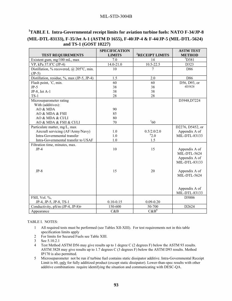
MIL-STD-3004B
93
1TABLE I. Intra-Governmental receipt limits for aviation turbine fuels: NATO F-34/JP-8 (MIL-DTL-83133), F-35/Jet A-1 (ASTM D 1655), F-40/JP-4 & F-44/JP-5 (MIL-DTL-5624)
and TS-1 (GOST 10227)
TEST REQUIREMENTS SPECIFICATION
LIMITS
2RECEIPT LIMITS ASTM TEST
METHOD Existent gum, mg/100 mL, max 7.0 14 3D381 VP, kPa 37.8oC (JP-4) 14.0-21.0 10.5-22.5 D323 Distillation, % recovered, @ 205oC, min. (JP-5)
10 7 D86
Distillation, residue, %, max (JP-5, JP-4) 1.5 2.0 D86 Flash point, ˚C, min. JP-5 JP-8, Jet A-1 TS-1
60 38 38 28
60 38 38 28
D56, D93, or 4D3828
Microseparometer rating D3948,D7224 With (additives): AO & MDA AO & MDA & FSII AO & MDA & CI/LI AO & MDA & FSII & CI/LI
90 85 80 70
560
Particulate matter, mg/L, max Aircraft servicing (AF/Army/Navy) 1.0 0.5/2.0/2.0 Intra-Governmental transfer 1.0 62.0 Intra-Governmental transfer to USAF 1.0 1.5
D2276, D5452, or Appendix A of
MIL-DTL-83133
Filtration time, minutes, max. JP-4 10 15 Appendix A of
MIL-DTL-5624 Appendix A of
MIL-DTL-83133
JP-8 15 20 Appendix A of MIL-DTL-5624
Appendix A of MIL-DTL-83133
FSII, Vol. %, D5006 JP-4, JP-5, JP-8, TS-1 0.10-0.15 0.09-0.20
Conductivity, pS/m (JP-4, JP-8)9 150-600 50-700 D2624 Appearance C&B C&B8
TABLE I. NOTES:
1 All required tests must be performed (see Tables XII-XIII). For test requirements not in this table specification limits apply
2 For limits for Secured Fuels see Table XIII. 3 See 5.10.2.1 4 Test Method ASTM D56 may give results up to 1 degree C (2 degrees F) below the ASTM 93 results.
ASTM 3828 may give results up to 1.7 degrees C (3 degrees F) below the ASTM D93 results. Method IP170 is also permitted.
5 Microseparometer not be run if turbine fuel contains static dissipator additive. Intra-Governmental Receipt Limit is 60, only for fully additized product (except static dissipator). Lower-than-spec results with other additive combinations require identifying the situation and communicating with DESC-QA.

MIL-STD-3004B
94
6. Where products may be received through a fixed-placed filter vessel, the limits apply to the sample taken after the receipt filter. Samples taken before the receipt filter are for information purposes only. Notify the local QSR for any investigation and/or corrective action (info the DESC Region Quality Manager)>
7 For Navy use only. Particulate matter of 8.0 mg/L, maximum, is acceptable for usage on transfers from shore tankage to pier side manifolds; fleet oilers, barges, tankers, and U. S. Naval vessels.
8 Clear and Bright at ambient temperature, as measured where the sample is taken. If the product is not Clear and Bright at ambient temperature, this test be conducted at 70 ˚F. An investigation would become necessary should the product fail at 70 ˚F. Steps should be taken (particularly pipeline operations) to confirm that hazy conditions are a result of water and not air. To make this determination: collect a sample of the product in question in a clean, clear glass bottle, place the sample on a flat surface and ascertain as to whether the bubbles in the product rise or fall. In cases where the bubbles rise, the hazy condition is a result of air in the product and should not be a cause for rejection. Further investigation may be warranted, but this simple test may prevent unfounded product rejections.
9 The conductivity must be between 150 and 600 pS/m for JP-8 (F-34), and JP-4 (F-40); and 50-600 pS/m for F-35, at ambient temperature of 29.4 degrees C (85 degrees F), whichever is lower, unless otherwise directed by the procuring activity. JP-8 with thermal stability improver additive, the conductivity limit must be between 150 and 700 pS/m at ambient temperature or 29.4 degrees C (85 degrees F), whichever is lower, unless otherwise directed by the procuring activity.
1TABLE II. Intra-Governmental receipt limits for fuel system icing inhibitor,
MIL-DTL-85470, NATO S-1745
TEST REQUIREMENTS SPECIFICATION
LIMITS
RECEIPT LIMITS ASTM TEST
METHOD Total water, wt. %, max. 0.10 0.40 D1364
TABLE II NOTES: 1 All required tests must be performed (see Table XXII, B-2 requirements). For test requirements not in Table
XXII, specification limits apply.
1TABLE III. Intra-Governmental receipt limits for fuel, naval, distillate, NATO, F-76,
(MIL-DTL-16884) TEST REQUIREMENTS SPECIFICATION
LIMITS
RECEIPT LIMITS ASTM TEST
METHOD Color, ASTM, max. 3 24 D1500 Ash, wt. %, max. 0.005 0.010 D482 Distillation 3D86 90% evaporation, °C 357 360 End point, °C 385 388 Water & sediment, Vol. %, max. 0.05 0.1 D2709 Particulate contamination, mg/L, max. 10.0 415.0 D6217 or D5452 Storage Stability total insoluble, mg/100 ml max.
3.0 6.05 D5304
TABLE III. NOTES:
1 All required tests must be performed (see Table XV). For test requirements not in this table specification limits apply.
2 See 5.10.5.2.

MIL-STD-3004B
95
3 As the end point of the distillation is approached, if either a thermometer reading of 385 °C or a decomposition point is observed, discontinue the heating and resume the procedure as directed in ASTM D86.
4 Shoreside-use only.
5 Storage Stability results greater than 3.0 mg/100 ml. be reported to DESC-QA.
1TABLE IV.
Intra-Governmental receipt limits for fuel oil, diesel, A-A-52557 and ASTM D975 TEST REQUIREMENTS SPECIFICATION
LIMITS
RECEIPT LIMITS ASTM TEST
METHOD Ash, wt. %, max 0.01 0.025 D482 Particulate contamination, mg/L, max., A-A-52557
10 20 D6217
Distillation, °C D86 90%, vol., Recovered
Grade No.1-D S15 or No.1-D S500 (ASTM D975) or LS 1-D (A-A-52557), max.
288 293
Grade No.2-D S15 or No.2-D S500 (ASTM 975) or LS 2-D (A-A-52557)
min. 282 277 max. 338 343
TABLE IV NOTES: 1 All required tests must be performed (see Table XV). For test requirements not in this table specification limits
apply.

MIL-STD-3004B
96
1TABLE V. Intra-Governmental receipt limits for fuel oil, diesel, F-54
TEST REQUIREMENTS SPECIFICATION LIMITS
RECEIPT LIMITS
ASTM TEST METHOD
Ash, Wt. %, max 0.01 0.025 D482 Color, max 5 6 D1500 Particulate contamination, mg/L, max.
10 20 D6217 2 EN12662
Flash Point, °C (°F), min 56(133) 55 (131) D93 Distillation, ° D86 %v/v recovered at 180 degrees C (356 degrees F), max vol.,
10
12
% v/v recovered at 340 degrees C (644 degrees F) min
95
93
Oxidation Stability, mg100ml,max 3
1.5 2.5 D2274
3 EN12205
TABLE V NOTES:
1 All required tests must be performed (see Table XV). For test requirements not in this table specification limits apply.
2. Total contamination requirement for F-54 is max 24 g/m3 as per EN12662 3. Total oxidation stability n requirement for F-54 is max 25 g/m3 as per EN12205

MIL-STD-3004B
97
1TABLE VI. Intra-Governmental receipt limits for gasoline, unleaded, NATO F-67,
STANAG 7090
TEST REQUIREMENTS
SPECIFICATION LIMITS (/F-67)
RECEIPT LIMITS
ASTM TEST METHOD
Color Clear See note 2 See note 3 Existent gum, mg/100mL, max. 5 7 D381 Octane number, motor/research, min. 85.0/95.0 D2700/D2699 VP, kPa D5191 Class A 45.0-60.0 43.0-62.0 Class B 45.0-70.0 43.0-72.0 Class C/C1 50.0-80.0 48.0-82.0 ClassD/D1 60.0-90.0 58.0-92.0 Class E//E1 65.0-95.0 63.0-97.0 Class F/F1 70.0-100.0 68.0-102.0 Distillation, volume %, evaporated D86 Class A@ 70oC @100oC @150oC Final boiling pt. (oC)
20.0-48.0 46.0-71.0 75.0, min
210
18.0-50.0 44.0-73.0 73.0,min
204
Class B @ 70oC @100oC @150oC Final boiling pt. (oC)
20.0-48.0 46.0-71.0 75, min.
210
18.0-50.0 44.0-73.0 73.0, min
204
Class C/C1 @ 70oC @100oC @150oC Final boiling pt. (oC)
22.0-50.0 46.0-71.0 75.0, min.
210
20.0-52.0 44.0-73.0 73.0, min.
204
Class D/D1 @ 70oC @100oC @150oC Final boiling pt. (oC)
22.0-50.00 46.0-71.0 75.0,min
210
20.0-52.0 44.0-73.0 73.0, min.
204
Class E/E1 @ 70oC @100oC @150oC Final boiling pt. (oC)
22.0-50.0 46.0-71.0 75.0, min.
210
20.0-52.0 44.0-73.0 73, min.
204
Class F/F1 @ 70oC @100oC @150oC Final boiling pt. (oC)
22.0-50.0 46.0-71.0 75.0, min.
210
20.0-52.0 44.0-73.0 73.0, min.
204
TABLE VI. NOTES:
1 All required tests must be performed (see Table XIV). For test requirements not in this table specification limits apply.
2 See paragraph 5.10.3.2. 3 Test method is Method 103.6 in FED-STD-791.

MIL-STD-3004B
98
1TABLE VII. Intra-Governmental receipt limits for automotive spark ignition engine fuel, ASTM D 4814 and gasohol, automotive, unleaded, A-A-52530
TEST REQUIREMENTS SPECIFICATION LIMITS
RECEIPT LIMITS
ASTM TEST METHOD
Existent gum, mg/100mL, max2 5 6 D381 Antiknock index, min 3 Limited Grade 87 86
D2700/D2699
Regular Grade 89 88 Premium Grade 91 90 VP kPa, max1, 2 D4953, D5190,
D5191 Class AA 54 57 Class A 62 65 Class B 69 72 Class C 79 82 Class D 93 96 Class E 103 107 Alcohol, contents, vol. %, max4 10 11 D4815 / D5599 Water tolerances, degree C See Table 13, ASTM +1 from degree C See Note 5 D4814 Table 13,
ASTM 4814
TABLE VII. NOTES:
1 All required tests must be performed (see Table XIV). For test requirements not in this table specification limits apply.
2 Value shown for gasohol based on the values of the base gasoline. (see 5.10.4.5 for VP).
3 Average of research and motor octane numbers or (R+M)/2.
4 These requirements only apply to gasohol.
5. Maximum temperature allowable before separation into two phases by addition of 0.1 % water

MIL-STD-3004B
99
TABLE VIII. Minimum frequency for testing dormant petroleum products
PRODUCT DESCRIPTION MINIMUM TESTING FREQUENCY
(MONTHS) BULK PACKAGED
Gasoline, Aviation 6 6 Gasoline, Automotive1 6 12 Turbine Fuels, Aviation1 6 12 Diesel Fuels 6 12 Kerosene 6 12 Fuels, Burner 6 12 Fog Oils 6 12
TABLE VIII. NOTES:
1 Product stored in collapsible containers be tested every month as a minimum.

MIL-STD-3004B
100
TABLE IX. Minimum sampling and testing requirements for petroleum products.
LOCATION OF STOCKS T
YPE
ST
OR
AG
E
WHEN SAMPLED
1TYPE SAMPLE
2TESTING REQUIRED
REMARKS
1 Upon procurement at: refineries, blending installations, etc. and at main installations including national depots & ocean-importing points on establishment of new batches.
Bulk After establishment of new batch.
Upper, middle, and lower composite, or all-level composite from each storage tank.
A Samples be retained IAW solicitation, contract and/or QCP requirements.
2 / Storage tanks and pipelines, for Pipeline Shipments or Vessel Loadings of Government Stocks.
2a Storage tanks Bulk Before shipment or loading
Upper, middle, and lower composite, or all-level composite from each storage tank.
Appearance, API gravity, color, flash point, particulate content, filtration time, FSII, water reaction (as applicable)
Government-owned stocks in tanks that have been tested previously within 90 days need only Type C. Referee sample be retained.
2b Pipelines Bulk Immediately after start of shipment or loading
Line sample, downstream of filter
C
2c Pipelines Bulk Hourly after starting shipment or loading
Line sample, downstream of filter
Visual
2d Pipelines Bulk During Loading or Shipment
Representative line Composite IAW API MPMS,Chapters 8.1 or 8.2.
Retained composite Sample to be retained as Referee. Testing to be conducted be based on the situation.
SER
IES
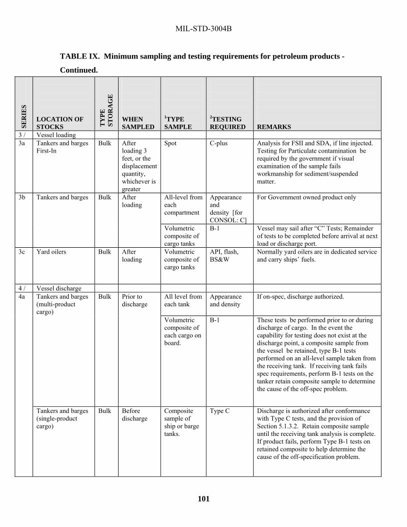
MIL-STD-3004B
101
TABLE IX. Minimum sampling and testing requirements for petroleum products -
Continued.
LOCATION OF STOCKS T
YPE
ST
OR
AG
E
WHEN SAMPLED
1TYPE SAMPLE
2TESTING REQUIRED
REMARKS
3 / Vessel loading 3a Tankers and barges
First-In Bulk After
loading 3 feet, or the displacement quantity, whichever is greater
Spot C-plus Analysis for FSII and SDA, if line injected. Testing for Particulate contamination be required by the government if visual examination of the sample fails workmanship for sediment/suspended matter.
3b Tankers and barges Bulk After loading
All-level from each compartment
Appearance and density [for CONSOL: C]
For Government owned product only
Volumetric composite of cargo tanks
B-1 Vessel may sail after “C” Tests; Remainder of tests to be completed before arrival at next load or discharge port.
3c Yard oilers Bulk After loading
Volumetric composite of cargo tanks
API, flash, BS&W
Normally yard oilers are in dedicated service and carry ships’ fuels.
4 / Vessel discharge 4a Tankers and barges
(multi-product cargo)
Bulk Prior to discharge
All level from each tank
Appearance and density
If on-spec, discharge authorized.
Volumetric composite of each cargo on board.
B-1 These tests be performed prior to or during discharge of cargo. In the event the capability for testing does not exist at the discharge point, a composite sample from the vessel be retained, type B-1 tests performed on an all-level sample taken from the receiving tank. If receiving tank fails spec requirements, perform B-1 tests on the tanker retain composite sample to determine the cause of the off-spec problem.
Tankers and barges (single-product cargo)
Bulk Before discharge
Composite sample of ship or barge tanks.
Type C Discharge is authorized after conformance with Type C tests, and the provision of Section 5.1.3.2. Retain composite sample until the receiving tank analysis is complete. If product fails, perform Type B-1 tests on retained composite to help determine the cause of the off-specification problem.
SER
IES

MIL-STD-3004B
102
TABLE IX. Minimum sampling and testing requirements for petroleum products - Continued.
LOCATION OF STOCKS T
YPE
ST
OR
AG
E
WHEN SAMPLED
1TYPE SAMPLE
2TESTING REQUIRED
REMARKS
4b Dock/discharge manifold header
Bulk During discharge
Sample IAW API MPMS, Chapter 8, commencing one half hour after start of discharge and each hour after until completion of the discharge. One-half quart to be taken each time. Sample to be composited after completion of discharge. Also, one gallon at one hour, midpoint, and one hour prior to completion.
Retained composite 3Particulate
Retained for referee tests. For barge receipts directly into A.F. bases, refer to agreement of minimum standards .
Dock/discharge manifold header
During discharge
For split cargo discharges where one product is JP-5, JP-8, or F-76, and other product is JP-4, MOGAS, or AVGAS, a dock header sample be taken during discharge of the JP-5 or JP-8 or F-76 one half hour after start of discharge and hourly thereafter.
Flash point
4c After receipt of fuel by waterborne transport.
Bulk After receipt of fuel.
Upper, middle, and lower composite, or all-level Composite. (from each storage tank)
Type B-1 Also, JFTOT after JP-4/JP-8/JPTS receipt.
4d Shipboard JP-5 De-fuels for return to Defense Working Capital Fund inventory
Bulk Before Discharge
Upper, middle, and lower composite or all-level composite (from each storage tank).
Type B-1 plus thermal stability
5 / Pipeline/TC/TT receipts.
5a During pipeline receipt
Bulk At point of transfer
Upon commencing receipt, hourly samples be taken of sufficient volume that permit a 5 gallon composite sample to be made and retained.
Visual Retain composite until the Type B-1 of the receiving tank passes.
5b After receipt of fuel via mode used for more than one product.
Bulk After receipt of fuel
Upper, middle, and lower composite, or all-level composite. (from each storage tank)
Type B-1
SER
IES

MIL-STD-3004B
103
LOCATION OF STOCKS T
YPE
ST
OR
AG
E
WHEN SAMPLED
1TYPE SAMPLE
2TESTING REQUIRED
REMARKS
5c After receipt of fuel via a dedicated mode.
Bulk After receipt of fuel.
Upper, middle, and Lower composite, or all-level composite. (from each storage tank)
Type C, except on initial filling or change of grade. Then, B-1 would be required.
SER
IES

MIL-STD-3004B
104
TABLE IX. Minimum sampling and testing requirements for petroleum products - Continued.
LOCATION OF STOCKS T
YPE
ST
OR
AG
E
WHEN SAMPLED
1TYPE SAMPLE
2TESTING REQUIRED
REMARKS
6 / Transfers within installation or depot
6a Through a dedicated system.
Inst
all
&
Dep
ots After receipt of
fuel Upper, middle, and lower composite, or all-level composite.
Type C Samples be retained for two months for referee purposes.
6b Through a common system.
Inst
alla
tions
&
Dep
ots
After receipt of fuel.
Upper, middle, and lower composite, or all-level composite.
Type B-1
7 Dormant Stocks wherever located.
Bul
k
Periodically, as required by TABLE VIII.
Upper. middle and lower composite or all-level composite (see remarks).
B-2 or A (see remarks)
a. Separate samples; upper, middle, and lower be taken and tested to establish homogeneity. If homogenous these samples be mixed for required tests. If not, perform B-2 tests on each level of product. b. Additional tests may be performed at the discretion of the owning or custodial authority, having regard to type of product, age of stock, conditions of storage, etc..
8 Filling Points for road and rail tank car containers, or other equipment.
Bul
k
Daily on first container filled, and on changeover to fresh feed tank after completion of line displacement from the fresh feed tank.
Line sample, downstream of filter
Type C
9 In rail tank cars, Inter-Modal Containers (ISO-Containers), and road tank vehicles and refuelers used in over the road transportation
Bul
k
Both after loading and before discharge
All level sample from the rail car or vehicle.
Appearance on each compartment Gravity/Density on composite
See note 5.
SER
IES

MIL-STD-3004B
105
LOCATION OF STOCKS T
YPE
ST
OR
AG
E
WHEN SAMPLED
1TYPE SAMPLE
2TESTING REQUIRED
REMARKS
10 Tanks containing interface mixtures from pipeline for re-injection.
Bulk Before re-injection Upper, middle, and lower composite, or all-level composite.
Type B-3 Re-injection of interface product is to be under the technical control of the pipeline authority, or IAW with O.A.
SER
IES

MIL-STD-3004B
106
TABLE IX. Minimum sampling and testing requirements for petroleum products - Continued.
LOCATION OF STOCKS
WHEN SAMPLED
1TYPE SAMPLE
2TESTING REQUIRED
REMARKS
11 Packaged fuel stocks wherever stored
Pack
aged
(a) Periodically as required by Table VIII. (see remark) (b) When contamination or deterioration of product is suspected. (c) When identity is uncertain.
Representative sample IAW API MPMS, Chapter 8
6 Type B-2 Where an agreed inspection period has not been stipulated the product is to be inspected at least annually.
12 Refueler trucks, skid mounted refuelers, or other dispensing equipment. B
ulk
(a) Daily (b) 8 Monthly
Line sample, downstream of filter. After re-circulation of fuel prior to the first refueling of the day.
See remarks (a) Check for (visual)color and appearance, and water & sediment (Aqua-Glo or AEL or equivalent). (b) 7 Laboratory analyses for water & sediment
13 Collapsible fabric tanks (bags) and drums on the establishment of tactical refueling systems.
Bul
k
(a) Initial fill and before issue (b) Daily - before issue (c) 8 Monthly
(a) After the filter separator (b) After filter separator. Note: After re-circulation of fuel prior to the first refueling of the day. (c) After filter separator
(a) See remarks
(a) API, visual check for appearance, water, sediment and fiber (Aqua-Glo or AEL and filter membrane color rating for turbine fuels) (b) Visual check for color, appearance, free water (Aqua-Glo or AEL for Turbine Fuels)and particulates (AEL or equivalent) (c) 7 Laboratory analysis for water and sediment.
SER
IES
TY
PE
STO
RA
GE

MIL-STD-3004B
107
LOCATION OF STOCKS
WHEN SAMPLED
1TYPE SAMPLE
2TESTING REQUIRED
REMARKS
14 Collapsible fabric tanks (bags) and drums used for wholesale and retail other than series 13 above (Aviation and Ground fuel) B
ulk
(a) Initial fill-before issue-Note: After recirculation of fuel (b) Daily –before use. Note: After recirculation of fuel prior to the first refueling of the day. (c) 8 Monthly
(a) After the filter separator
(b) After filter separator (c) After filter separator
B-1
(b) C and See remarks (c) See Remarks
(b) Aviation Turbine Fuels containing additives be checked for FSII and conductivity. (c) 7 Laboratory analysis for sediment and water.
LEGEND Table IX Type “A” Test - Complete specification.
Type “B-1” Test - Partial analysis comprising the checking of principal characteristics most likely to have been affected in the course of moving the product.
Type “B-2” Test - Partial analysis to check characteristics susceptible to deterioration because of age.
Type “B-3” Test- Partial analysis for contamination; in particular, for controlling the return )or reintroduction) of pipeline interface products.
Type “C” Test – Quick, simple, partial analysis for verification of product quality, to ensure that no change has taken place.
TABLE IX. NOTES:
1 Use the API MPMS for sampling methods (see 4.7).
2 See Tables X through XXII for the types of test required on the various products.
3 The average particulate content of the 3 fuel samples should not exceed 2 mg/L; however, the first and last samples are obtained under severe
discharge conditions they may show high particulate content. Solid contamination while extremely objectionable is a physical contaminant
which can be removed under proper conditions with proper equipment, and since the product at this point is Government owned, discharge
operations not be discontinued for this reason. However, the contracting officer, Defense Energy Support Center, and the quality assurance
representative at the loading point be advised of any high particulate results obtained. This information be used for future planning purposes
and for determining possible cleaning actions necessary on the vessel involved. This note is not applicable to internal Navy transfers.
4 Flash Point at the receiving point is not required for product that is to be use by the U.S. Army. This fuel is tested in accordance with Army
quality surveillance program AR 710-2.
SER
IES
TY
PE
STO
RA
GE

MIL-STD-3004B
108
5 If unable to take an all-level sample from the truck compartment prior to discharge, then take an in-line sample at or near the off-loading header
during the discharge, immediately upon product displacement of the receipt manifold/hose.
6 No receiving tests are necessary on packaged products, provided the containers are intact and markings adequately identify the product.
7 When laboratory tests of material from dispensing and handling equipment show evidence of free water or a sediment level exceeding 0.5 mg/L
for aviation fuels (2.0 mg/L for U.S. Army and U.S. Navy), or 10.0 mg/L for diesel fuel, that equipment be re-sampled and deadlined pending
laboratory confirmation of the initial results. If the second laboratory analysis confirms the presence of free water or a sediment exceeding the
above limits, improvement in fuel quality must be made.
8 Filter separator performance is to be checked every 30 days.

MIL-STD-3004B
109
TABLE X. Tests required, aviation gasoline PROPERTIES B-1 TEST B-2 TEST B-3 TEST C TEST
Appearance1 X X X X Particulate matter 2,4 X X X Color (Visual) X X X X Density or API gravity X X X X Distillation X X X Copper strip corrosion X X X Existent gum X X Vapor pressure X X Water reaction X X X Lean mixture rating3 X X X Rich mixture rating3 X X Lead content X X Potential gum X
TABLE X. NOTES:
1 Obtain sample in a clear round one quart glass bottle, swirl the bottle vigorously so a vortex is formed. Visually check for sediment at the
point of the vortex. If sediment is visible, an investigation is necessary in order to determine the source of the contaminant (a spot larger
than 3 mm diameter indicates corrective action may be required to prevent the delivery of contaminated fuel).
2 Perform only if visual sediment is present.
3 Perform only if Lead content was performed and failed the specification requirement. If the capability does not exist to perform this test
at the terminal, a sample be sent to the nearest Service laboratory that does have the capability. In the event operational necessity
dictates issue of product before results are obtained from the Service laboratory, shipments may be made; however, when laboratory
results indicate failure, notify DESC-QA.
4 AVGAS samples be checked for solids and water. When no laboratory is available to perform these tests, solids be determined visually
upstream of filter separators and by the particle assessment method downstream of the filter separator.

MIL-STD-3004B
110
TABLE XI Tests required, lubrication oils 1,2
PROPERTIES B-1 TEST C TEST Appearance (to include visual sediment & water) X X Emulsion test X Gravity X X Viscosity X3 Flash point X Foam test X Water (by centrifuge) X3 X4 Solid contaminants X
TABLE XI NOTES: 1 For application of these tests see Table IX.
2 B-2 tests are listed in Tables XVII-XX.
3 For MIL-PRF-17331 and MIL-PRF-9000 viscosity is not required unless the tank has been dormant for 3 months and water (by
centrifuge) is only required if the oil fails appearance because of water contamination (cloudiness).
4 Only required if the oil fails appearance because of water contamination (cloudiness).

MIL-STD-3004B
111
TABLE XII. Tests required, aviation turbine fuels PROPERTIES B-1 TEST B-2 TEST B-3 TEST C TEST
Appearance1 X X X X Color (visual) X X X X Density or API gravity X X X X Particulate matter X X X Distillation X X X Copper strip corrosion X X X Freezing point X X X Existent gum X X X Vapor pressure (JP-4 only) X X X Flash point (except JP-4) X X X X Water reaction X X X Lead content (If contaminated with leaded fuels suspected) X X X Fuel system icing inhibitor5 X X X Filtration time (JP-4 & JP-8) (Not performed on JP-5) X X X Water separation index (JP-4 and JP-8)2, 3 X X X Conductivity (JP-4 and JP-8)4 X X X Thermal stability (B-1 requirement applies only to JPTS and marine mode receipt tank sample)
X X
Color (Saybolt) X Acid number X
TABLE XII NOTES:
1 Obtain sample in a clear round one quart glass bottle, swirl the bottle vigorously so a vortex is formed. Visually check for sediment at the
point of the vortex. If sediment is visible, an investigation is necessary in order to determine the source of the contaminant (a spot larger
than 3 mm diameter indicates corrective action may be required to prevent the delivery of contaminated fuel).
2 If the capability does not exist to perform this test at the terminal, a sample be sent to the nearest Service laboratory that does have the
capability. In the event operational necessity dictates issue of product before results are obtained from the Service laboratory, shipments
may be made, however, when laboratory results indicate failure, notify DESC-QA.
3 Water separation index, modified, testing is not performed if the fuel contains conductivity additive.
4 If fuel contains conductivity additive, CU readings should be taken within two minutes of sampling.
5. If product contains FSII, product should be check on delivery into a bulk storage tank and every month thereafter if stock remains
dormant, and no deliveries have been made into the tank.

MIL-STD-3004B
112
1TABLE XIII. Support for Secured Fuels
JP-5 Jet A Jet A-1 JP-8 CHARACTERISTIC
LIMITS
Min.
Max.
Min.
Max.
Min.
Max.
Min.
Max. Gravity, API @ 60ºF D1298/D4052
36 48 37 51 37 51 37 51
Density at 15 °C (kg/m) 788 845 775 840 775 840 775 840 Weight: lbs/USG Calculated
6.6 7.0 6.5 7.0 6.5 7.0 6.5 7.0
Distillation (°C) D86
10% 205 205 205 205 20% RPT RPT 50% RPT RPT RPT RPT 90% RPT RPT RPT RPT End Point 300 300 300 300
Freezing point, °C D5972/D2386
-46 -40 -47 -47
Flash point, °C D93/D56
60 38 38 38
Particular Matter (mg/L) D5452
0.5 0.5 0.5 0.5
Conductivity (pS/m)2
D2624 RPT RPT 50 700
Copper strip corrosion D130
1 1 1 1
Water reaction D1094
1b 1b 1b 1b
Existent gum (mg/100 mL) D381
7.0 7.0 7.0 7.0
FSII, (% Vol.) 2
D5006 0.09 0.20 0.09 0.20
Acidity, total, mg KOH/g D3242
0.015 0.10 0.10 0.015
Thermal Stability 4,1 D3241
Change in pressure drop, mm Hg
25 25 25 25
Heater tube deposit, visual rating 5
<3 <3 <3 <3
Lubricity (BOCLE) 1 Report Report Report Report Appearance 3
TABLE XIII. NOTES:
1 Results cited in this table apply to samples taken downstream of final filtration from refueler units or hydrant operating tanks and correspond to the appropriate specification limits, unless otherwise indicated. New test requirement: Acid Number ASTM D3242, JFTOT ASTM 3241, BOCLE ASTM D5001. In geographical locations where these tests cannot be performed in support of a secure fuel mission the DESC Regional Quality Manager notify AFPET. The fuel is acceptable for use if it meets remainder of table XIII testing requirements.

MIL-STD-3004B
113
2 The FSII and conductivity limits above are use limits. Only FSII which meets specification MIL-DTL-85470, Inhibitor, Icing, Fuel System, High Flash, NATO Code Number S-1745 is to be used.
3 Water: Fuel must be clear and free of water on visual examination. Sample be taken downstream of filter separator.
4 2.5 hours at a control temperature of 260 degrees C minimum. 5 Peacock or abnormal color deposits result in a failure.
Point of Contact Secured Fuel Advance Team personnel requiring support with fuel sampling and/or testing are to contact the cognizant Service Control Point for refueling on military installations and DESC Region for all other locations to identify those offices and personnel who participate.
Testing: If complete testing cannot be performed at a local base laboratory or if insufficient time exists for the sample to be forwarded to an Air Force area laboratory, then local commercial testing be performed. The cognizant DESC Region Quality Manager be contacted to arrange for required testing. See paragraph 5.7.3 of this document for invoice and payment procedures associated with testing performed at contract and non-contract locations.
TABLE XIV. Tests required, automotive gasoline PROPERTIES B-1 TEST B-2 TEST B-3 TEST C TEST
Appearance X X X X Color X X X X Water and Solids (Visual Check) X X X X Density or API gravity X X X X Distillation X X X Vapor pressure X X Copper strip corrosion X X Existent gum X X1 Knock rating (RON and MON) X2 X2 Oxidation stability X Water tolerance3 X X X
TABLE XIV. NOTES:
1 Unwashed gum, without solvent wash, not increase by more than 2 mg as compared to the original product. In the event of gum increase exceeding 2 mg, a Type A test, as defined in the legend, be run.
2 Perform only if Lead Content is performed and fails and/or contamination with another product is suspected. In the case of pipeline, this test be performed when considered necessary.
3 Gasohol only.
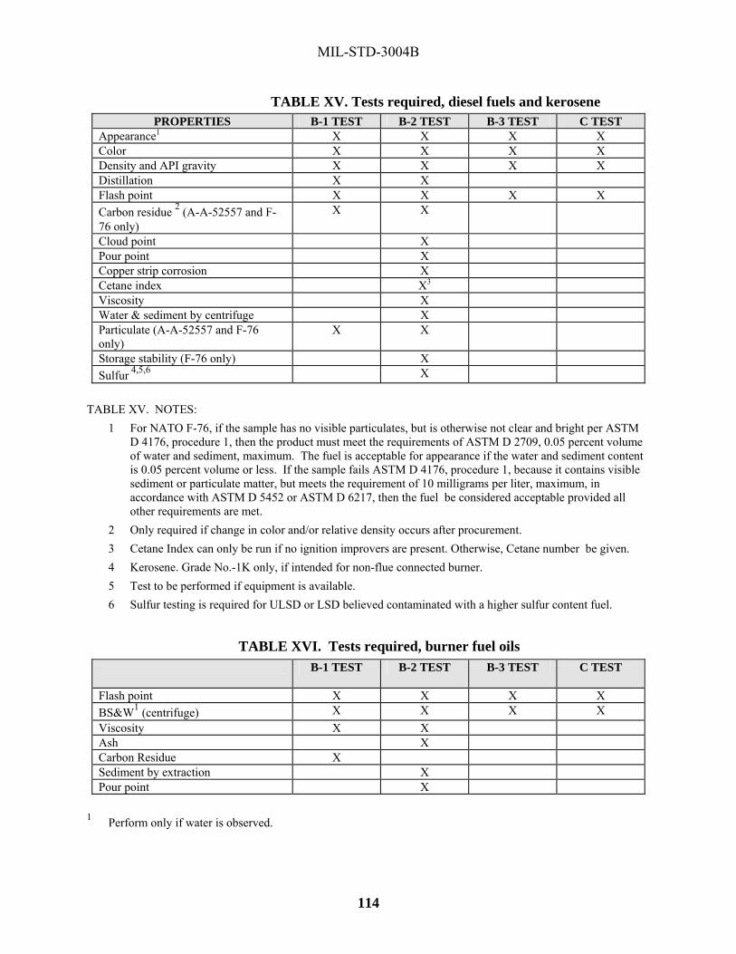
MIL-STD-3004B
114
TABLE XV. Tests required, diesel fuels and kerosene PROPERTIES B-1 TEST B-2 TEST B-3 TEST C TEST
Appearance1 X X X X Color X X X X Density and API gravity X X X X Distillation X X Flash point X X X X Carbon residue 2 (A-A-52557 and F-76 only)
X X
Cloud point X Pour point X Copper strip corrosion X Cetane index X3 Viscosity X Water & sediment by centrifuge X Particulate (A-A-52557 and F-76 only)
X X
Storage stability (F-76 only) X Sulfur 4,5,6 X
TABLE XV. NOTES:
1 For NATO F-76, if the sample has no visible particulates, but is otherwise not clear and bright per ASTM D 4176, procedure 1, then the product must meet the requirements of ASTM D 2709, 0.05 percent volume of water and sediment, maximum. The fuel is acceptable for appearance if the water and sediment content is 0.05 percent volume or less. If the sample fails ASTM D 4176, procedure 1, because it contains visible sediment or particulate matter, but meets the requirement of 10 milligrams per liter, maximum, in accordance with ASTM D 5452 or ASTM D 6217, then the fuel be considered acceptable provided all other requirements are met.
2 Only required if change in color and/or relative density occurs after procurement. 3 Cetane Index can only be run if no ignition improvers are present. Otherwise, Cetane number be given. 4 Kerosene. Grade No.-1K only, if intended for non-flue connected burner. 5 Test to be performed if equipment is available. 6 Sulfur testing is required for ULSD or LSD believed contaminated with a higher sulfur content fuel.
TABLE XVI. Tests required, burner fuel oils
B-1 TEST B-2 TEST B-3 TEST C TEST
Flash point X X X X BS&W1 (centrifuge) X X X X Viscosity X X Ash X Carbon Residue X Sediment by extraction X Pour point X
1 Perform only if water is observed.

MIL-STD-3004B
115
TABLE XVII. Type B-2 tests for lubricating oils SPECIFICATION
CHARACTERISTICS MIL-PRF-32033 VV-L-8251 SAE J 1899 SAE J 1966 Appearance / workmanship X X Color X Viscosity @ 100 °C X X X Viscosity @ 54 °C Viscosity @ 40 °C X X Viscosity @ -40 °C X Viscosity @ -54 °C X Relative density X X Flash point X X X X Pour point X X X X Neutralization number (acid/base) X X X Copper strip corrosion X X X X Corrosion & oxidation stability Evaporation loss X Precipitation number X Ash X X X Emulsion Foam test X Water content Particulate content / trace sediment X X Trace metals X Carbon residue X Sulfur Minimum retest frequency (months) 24 36 36 36 Visual check frequency (months) 12 12 12 Military symbol(s) PL-S RCO-2/3/4 Type II
Type III
NATO Numbers O-190 O-282, O-290 O-123, O-128 1065, 1080, 1100, 1120
O-113, O-117 TABLE XVII. NOTES: 1 Also, floc point and dielectric strength.

MIL-STD-3004B
116
TABLE XVII. Type B-2 tests for lubricating oils - Continued SPECIFICATION
CHARACTERISTICS MIL-PRF-2104 SAE J2360 MIL-PRF-3150 MIL-L-3918 Appearance / workmanship X X Color Viscosity @ 100 °C X X Viscosity @ 54 °C Viscosity @ 40 °C X X2 Viscosity @ -40 °C Viscosity @ -54 °C Relative density Flash point X X Pour point X X Neutralization number (acid/base) X Copper strip corrosion X X X Corrosion & oxidation stability X1 Evaporation loss X X Precipitation number Ash Emulsion Foam test X X Water content Particulate content / trace sediment Trace metals Carbon residue Sulfur Hydrolytic stability Minimum retest frequency (months) 36 24 24 24 Visual check frequency (months) 12 12 12 Military symbol(s) OE/HDO10,30,
40,15/40 GO75,80/90,
85/140 PL-M
NATO numbers O-237,238,1236 O-186,226,228 O-192
TABLE XVII. NOTES: 1 If capability exists. 2 Per temperature in specification.

MIL-STD-3004B
117
TABLE XVII. Type B-2 tests for lubricating oils - Continued SPECIFICATION CHARACTERISTICS MIL-PRF-6081 MIL-PRF-6085 MIL-PRF-6086 MIL-PRF-7808 Appearance / workmanship X X X X Color X X Viscosity @ 100 °C X Viscosity @ 54 °C X Viscosity @ 40 °C X3 X2 X Viscosity @ -40 °C X Viscosity @ -54 °C X X X2 Relative density Flash point X X X X Pour point X X Neutralization number (acid/base) X X X X Copper strip corrosion X X Corrosion & oxidation stability X X1 X Evaporation loss Precipitation number X Ash Emulsion Foam test X X Water content Particulate content / trace sediment X X Trace metals X Carbon residue Sulfur Hydrolytic stability Minimum retest frequency (months) 36 24 36 36 Visual check frequency (months) 12 12 12 12 Military symbol(s) OAI OGL,OGR NATO numbers O-132, O-133 O-147 O-153, O-155 O-148, O-163
TABLE XVII. NOTES: 1 If capability exists. 2 Per temperature in specification.

MIL-STD-3004B
118
TABLE XVII. Type B-2 tests for lubricating oils - Continued SPECIFICATION CHARACTERISTICS MIL-PRF-7870 MIL-PRF-9000 AGMA9005 MIL-L-11734 Appearance / workmanship X X Color X Viscosity @ 100 °C X X Viscosity @ 54 °C Viscosity @ 40 °C X3 X X2 Viscosity @ -40 °C X Viscosity @ -54 °C X2 Relative density Flash point X X X Pour point X X X Neutralization number (acid/base) X Copper strip corrosion Corrosion & oxidation stability X X1 Evaporation loss X X Precipitation number X Ash X Emulsion Foam test X Water content Particulate content / trace sediment X Trace metals Carbon residue Sulfur Hydrolytic stability Minimum retest frequency (months) 36 24 24 36 Visual check frequency (months) 12 Military symbol(s) 9250 NATO numbers O-142 O-278
TABLE XVII. NOTES: 1 If capability exists. 2 Per temperature in specification.

MIL-STD-3004B
119
TABLE XVII. Type B-2 tests for lubricating oils - Continued SPECIFICATION CHARACTERISTICS MIL-PRF-17331 MIL-PRF-21260 MIL-PRF-23699 DOD-PRF-24574Appearance / workmanship Color Viscosity @ 100 °C X X X X Viscosity @ 54 °C Viscosity @ 40 °C X X X Viscosity @ -40 °C X Viscosity @ -54 °C Relative density Flash point X X X X Pour point X X X X Neutralization number (acid/base) X X Copper strip corrosion X X Corrosion & oxidation stability X Evaporation loss X Precipitation number Ash Emulsion X Foam test X1 X X X Water content X Particulate content / trace sediment X Trace metals X Carbon residue Sulfur Hydrolytic stability X Minimum retest frequency (months) 24 24 36 36 Visual check frequency (months) 12 12 Military symbol(s) 2190-TEP PE-10,30,40,
15/40
NATO numbers O-250 C-640,C-642 O-156
TABLE XVII. NOTES: 1 Option A may be used for Government owned 2190 TEP if the conditions are met as required by ASTM D892

MIL-STD-3004B
120
TABLE XVII. Type B-2 tests for lubricating oils - Continued SPECIFICATION CHARACTERISTICS MIL-PRE-26087 MIL-L-46014 MIL-PRF-46167 SAE J2362 Appearance / workmanship X Color X Viscosity @ 100 °C X1 X1 X Viscosity @ 54 °C Viscosity @ 40 °C X1 X1 X Viscosity @ -40 °C X Viscosity @ -54 °C Relative density Flash point X X X X Pour point X X X Neutralization number (acid/base) X X Copper strip corrosion X Oxidation stability X Evaporation loss Precipitation number X Ash Emulsion Foam test X X Water content Particulate content / trace sediment X Trace metals Carbon residue X Sulfur X Hydrolytic stability Minimum retest frequency (months) 36 36 24 24 Visual check frequency (months) Military symbol(s) OEA-30 NATO numbers O-183
TABLE XVII. NOTES: 1 Per temperature in specification.
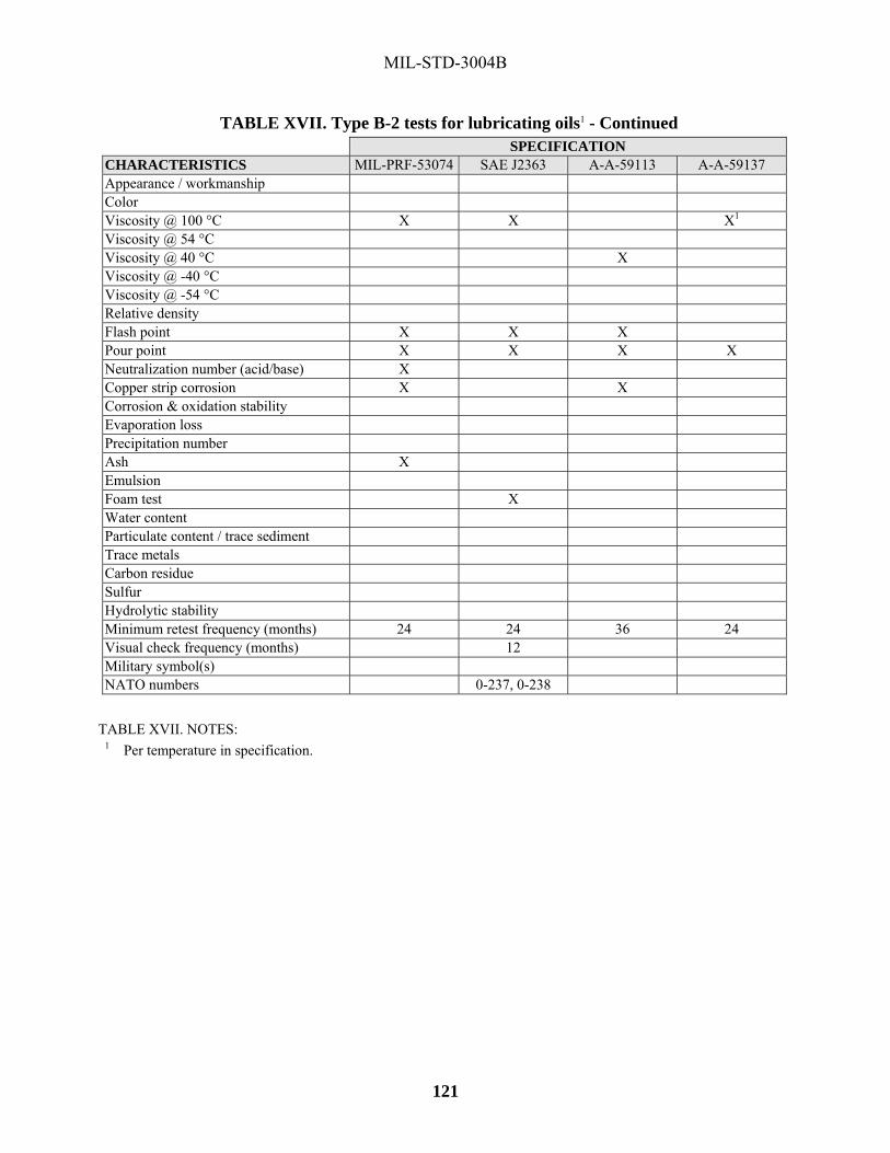
MIL-STD-3004B
121
TABLE XVII. Type B-2 tests for lubricating oils1 - Continued SPECIFICATION CHARACTERISTICS MIL-PRF-53074 SAE J2363 A-A-59113 A-A-59137 Appearance / workmanship Color Viscosity @ 100 °C X X X1 Viscosity @ 54 °C Viscosity @ 40 °C X Viscosity @ -40 °C Viscosity @ -54 °C Relative density Flash point X X X Pour point X X X X Neutralization number (acid/base) X Copper strip corrosion X X Corrosion & oxidation stability Evaporation loss Precipitation number Ash X Emulsion Foam test X Water content Particulate content / trace sediment Trace metals Carbon residue Sulfur Hydrolytic stability Minimum retest frequency (months) 24 24 36 24 Visual check frequency (months) 12 Military symbol(s) NATO numbers 0-237, 0-238
TABLE XVII. NOTES: 1 Per temperature in specification.

MIL-STD-3004B
122
TABLE XVII. Type B-2 tests for lubricating oils - Continued SPECIFICATION CHARACTERISTICS DOD-L-81846 DOD-PRF-85734 MIL-PRF-87100 Appearance / workmanship X X Color X Viscosity @ 100 °C X1 X1 X1 Viscosity @ 54 °C Viscosity @ 40 °C X1 X1 X1 Viscosity @ -40 °C X Viscosity @ -54 °C X X1 Relative density X Flash point X X X Pour point X X X Neutralization number (acid/base) X X Copper strip corrosion Corrosion & oxidation stability X X Evaporation loss X X X Precipitation number Ash Emulsion Foam test X X Water content Particulate content / trace sediment X X X Trace metals X X Carbon residue Sulfur Hydrolytic stability Minimum retest frequency (months) 24 36 36 Visual check frequency (months) 12 Military symbol(s) NATO numbers
TABLE XVII. NOTES: 1 Per temperature in specification.

MIL-STD-3004B
123
TABLE XVIII. Type B-2 tests for greases, semi-fluids, lubricants and other grease-like materials SPECIFICATION CHARACTERISTICS VV-P-2361 VV-G-632 VV-G-6712 SAE-AMS-G-
4343 Appearance / workmanship X X X Odor X Penetration (un-worked) X Penetration (worked) X X X Worked stability Dropping point / melting X X X X Oil separation X Evaporation loss / bleed X X Copper strip corrosion X X X X Oxidation stability (100 hours) Rust preventive properties X Water resistance Fuel resistance Free-acidity / free alkali X X Molybdenum disulfide content Boiling water immersion Water stability / emulsification Water content X Dirt (particles) X Load carrying capacity X3 Minimum retest frequency (months)
24 24 24 24
Visual check frequency (months) 12 Military symbol NATO numbers S-743 G-412 G-392
TABLE XVIII. NOTES: 1 Also neutralization number, viscosity & flash point. 2 Also ash content. 3 If capability exists.

MIL-STD-3004B
124
TABLE XVIII. Type B-2 tests for greases, semi-fluids, lubricants, and other grease-like materials – Continued
SPECIFICATION CHARACTERISTICS SAE-AMS-G-
6032 MIL-PRF-10924 MIL-G-14931 MIL-L-15719
Appearance / workmanship X X X X Odor X X Penetration (un-worked) X Penetration (worked) X X X Worked stability X X Dropping point / melting X X X Oil separation X Evaporation loss / bleed X X X Copper strip corrosion X X X X Oxidation stability (100 HRS) Rust preventive properties X Water resistance X X Fuel resistance Free-acidity / free alkali Molybdenum disulfide content Boiling water immersion Water stability / emulsification Water content Dirt (particles) X X Load carrying capacity X1 Minimum retest frequency (months)
24 24 24 24
Visual check frequency (months) 62 12 Military symbol GAA HTG NATO numbers G-363 G-403
TABLE XVIII. NOTES: 1 If capability exists. 2 Examine each 6 months for hardening.

MIL-STD-3004B
125
TABLE XVIII. Type B-2 tests for greases, semi-fluids, lubricants, and other grease-like materials – Continued
SPECIFICATION CHARACTERISTICS MIL-PRF-184582 MIL-L-19701 MIL-G-21164 MIL-DTL-23549 Appearance / workmanship X X X Odor X Penetration (un-worked) X Penetration (worked) X X X Worked stability X Dropping point / melting X X Oil separation X X X Evaporation loss / bleed X X X Copper strip corrosion X X Oxidation stability (100 HRS) Rust preventive properties X X Water resistance X Fuel resistance Free-acidity / free alkali Molybdenum disulfide content X X Boiling water immersion X Water stability / emulsification Water content Dirt (particles) Load carrying capacity X1 X1 X1 Minimum retest frequency (months)
24 36 24 24
Visual check frequency (months) Military symbol GMD NATO numbers G-353
TABLE XVIII. NOTES: 1 If capability exists. 2 Also volatile matter.

MIL-STD-3004B
126
TABLE XVIII. Type B-2 tests for greases, semi-fluids, lubricants, and other grease-like materials – Continued
SPECIFICATION CHARACTERISTICS MIL-PRF-23827 MIL-PRF-24139 DOD-G-24508 DOD-G-24650 Appearance / workmanship X X X X Odor X X X Penetration (un-worked) X Penetration (worked) X X X X Worked stability X X X Dropping point / melting X X X X Oil separation X X Evaporation loss / bleed X X X Copper strip corrosion X X X Oxidation stability (100 HRS) X Rust preventive properties X X Water resistance X X X Fuel resistance Free-acidity / free alkali Molybdenum disulfide content Boiling water immersion Water stability / emulsification Water content Dirt (particles) X X X Load carrying capacity X1 X1 Minimum retest frequency (months)
24 24 24
Visual check frequency (months) Military symbol NATO numbers G-354 G-450
TABLE XVIII. NOTES: 1 If capability exists.
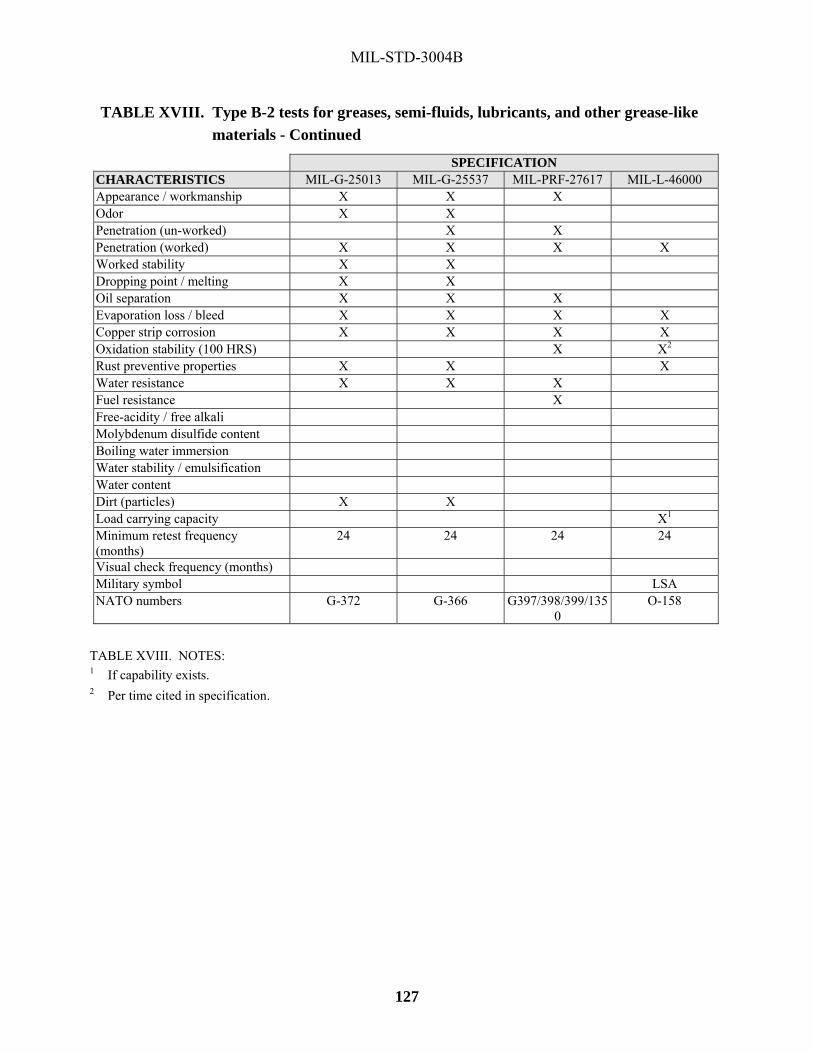
MIL-STD-3004B
127
TABLE XVIII. Type B-2 tests for greases, semi-fluids, lubricants, and other grease-like materials - Continued
SPECIFICATION CHARACTERISTICS MIL-G-25013 MIL-G-25537 MIL-PRF-27617 MIL-L-46000 Appearance / workmanship X X X Odor X X Penetration (un-worked) X X Penetration (worked) X X X X Worked stability X X Dropping point / melting X X Oil separation X X X Evaporation loss / bleed X X X X Copper strip corrosion X X X X Oxidation stability (100 HRS) X X2 Rust preventive properties X X X Water resistance X X X Fuel resistance X Free-acidity / free alkali Molybdenum disulfide content Boiling water immersion Water stability / emulsification Water content Dirt (particles) X X Load carrying capacity X1 Minimum retest frequency (months)
24 24 24 24
Visual check frequency (months) Military symbol LSA NATO numbers G-372 G-366 G397/398/399/135
0 O-158
TABLE XVIII. NOTES: 1 If capability exists. 2 Per time cited in specification.
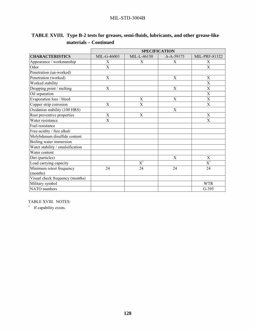
MIL-STD-3004B
128
TABLE XVIII. Type B-2 tests for greases, semi-fluids, lubricants, and other grease-like materials – Continued
SPECIFICATION CHARACTERISTICS MIL-G-46003 MIL-L-46150 A-A-59173 MIL-PRF-81322 Appearance / workmanship X X X X Odor X X Penetration (un-worked) Penetration (worked) X X X Worked stability X Dropping point / melting X X X Oil separation X Evaporation loss / bleed X X X Copper strip corrosion X X X Oxidation stability (100 HRS) X Rust preventive properties X X X Water resistance X X Fuel resistance Free-acidity / free alkali Molybdenum disulfide content Boiling water immersion Water stability / emulsification Water content Dirt (particles) X X Load carrying capacity X1 X1 Minimum retest frequency (months)
24 24 24 24
Visual check frequency (months) Military symbol WTR NATO numbers G-395
TABLE XVIII. NOTES: 1 If capability exists.

MIL-STD-3004B
129
TABLE XVIII. Type B-2 tests for greases, semi-fluids, lubricants, and other grease-like materials – Continued
SPECIFICATION CHARACTERISTICS MIL-G-81827 MIL-G-81937 MIL-PRF-83261 MIL-PRF-83363 Appearance / workmanship X X X X Odor X Penetration (un-worked) X X X Penetration (worked) X X X X Worked stability X X X X Dropping point / melting X X Oil separation X X X X Evaporation loss / bleed X X X X Copper strip corrosion X X Oxidation stability (100 HRS) X Rust preventive properties X X Water resistance X X X Fuel resistance Free-acidity / free alkali Molybdenum disulfide content X Boiling water immersion X Water stability / emulsification Water content Dirt (particles) X Load carrying capacity X1 X1 X1 Minimum retest frequency (months)
24 24 24 24
Visual check frequency (months) Military symbol NATO numbers G-396
TABLE XVIII. NOTES: 1 If capability exists.

MIL-STD-3004B
130
TABLE XVIII. Type B-2 tests for greases, semi-fluids, lubricants and other grease-like materials – Continued SPECIFICATIONCHARACTERISTICS MIL-PRF-85336 Appearance / workmanship Odor Penetration (un-worked) Penetration (worked) Worked stability Dropping point / melting Oil separation Evaporation loss / bleed X Copper strip corrosion X Oxidation stability (100 HRS) X Rust preventive properties X Water resistance Fuel resistance Free-acidity / free alkali Molybdenum disulfide content Boiling water immersion Water stability / emulsification X Water content Dirt (particles) Load carrying capacity X1 Minimum retest frequency (months)
24
Visual check frequency (months) Military symbol NATO numbers
TABLE XVIII. NOTES: 1 If capability exists.
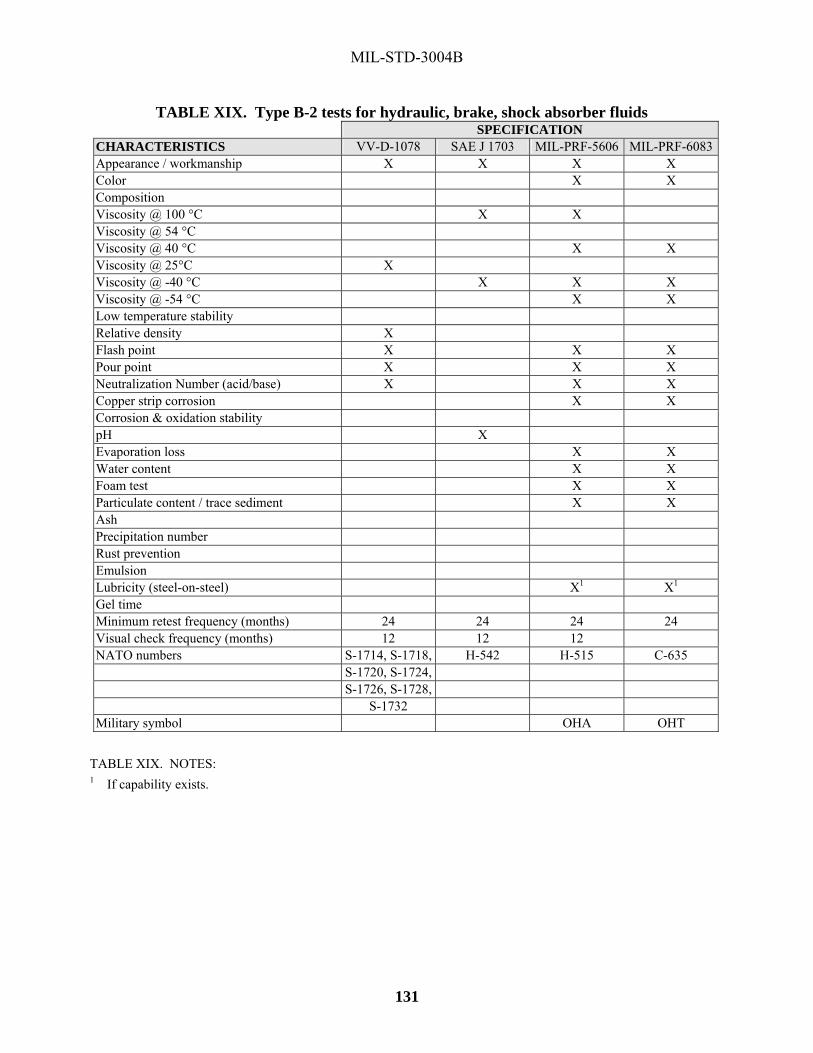
MIL-STD-3004B
131
TABLE XIX. Type B-2 tests for hydraulic, brake, shock absorber fluids SPECIFICATION CHARACTERISTICS VV-D-1078 SAE J 1703 MIL-PRF-5606 MIL-PRF-6083Appearance / workmanship X X X X Color X X Composition Viscosity @ 100 °C X X Viscosity @ 54 °C Viscosity @ 40 °C X X Viscosity @ 25°C X Viscosity @ -40 °C X X X Viscosity @ -54 °C X X Low temperature stability Relative density X Flash point X X X Pour point X X X Neutralization Number (acid/base) X X X Copper strip corrosion X X Corrosion & oxidation stability pH X Evaporation loss X X Water content X X Foam test X X Particulate content / trace sediment X X Ash Precipitation number Rust prevention Emulsion Lubricity (steel-on-steel) X1 X1 Gel time Minimum retest frequency (months) 24 24 24 24 Visual check frequency (months) 12 12 12 NATO numbers S-1714, S-1718, H-542 H-515 C-635 S-1720, S-1724,
S-1726, S-1728, S-1732
Military symbol OHA OHT TABLE XIX. NOTES: 1 If capability exists.

MIL-STD-3004B
132
TABLE XIX. Type B-2 tests for hydraulic, brake, shock absorber fluids - Continued SPECIFICATION CHARACTERISTICS MIL-DTL-17111 MIL-PRF-17672 MIL-H-194573 MIL-H-22072Appearance / workmanship X X X Color X X Composition Viscosity @ 100 °C X X Viscosity @ 54 °C X Viscosity @ 40 °C X X X X2 Viscosity @ 25°C Viscosity @ -40 °C X2 Viscosity @ -54 °C Low temperature stability Relative density X X Flash point X Pour point X X X Neutralization Number (acid/base) X X X Copper strip corrosion X Corrosion & oxidation stability pH X Evaporation loss X X X Water content X X X X Foam test X X X Particulate content / trace sediment X Ash X Precipitation number X X Rust prevention Emulsion X X Lubricity (steel-on-steel) X1 X1 Gel time Minimum retest frequency (months) 24 24 24 24 Visual check frequency (months) NATO numbers H-575 H-573 H-580 H-579 Military symbol 2075/2110/
2135-T-H
TABLE XIX. NOTES: 1 If capability exists. 2 Per temperature in specification. 3 Also, hydrolytic stability.

MIL-STD-3004B
133
TABLE XIX. Type B-2 tests for hydraulic, brake, shock absorber fluids - Continued SPECIFICATION CHARACTERISTICS MIL-PRF-27601 A-A-59354 MIL-PRF-46176 A-A-59290 Appearance / workmanship Color X Composition Viscosity @ 100 °C X X Viscosity @ 54 °C Viscosity @ 40 °C X X X2 Viscosity @ 25°C Viscosity @ -40 °C X Viscosity @ -54 °C X2 Low temperature stability Relative density X Flash point X X X Pour point X X Neutralization Number (acid/base) X X Copper strip corrosion Corrosion & oxidation stability pH X Evaporation loss Water content X Foam test X X Particulate content / trace sediment X Ash X Precipitation number Rust prevention X Emulsion Lubricity (steel-on-steel) X1 Gel time Minimum retest frequency (months) 24 24 24 24 Visual check frequency (months) NATO numbers H-547 Military symbol BFS
TABLE XIX. NOTES: 1 If capability exists. 2 Per temperature in specification.
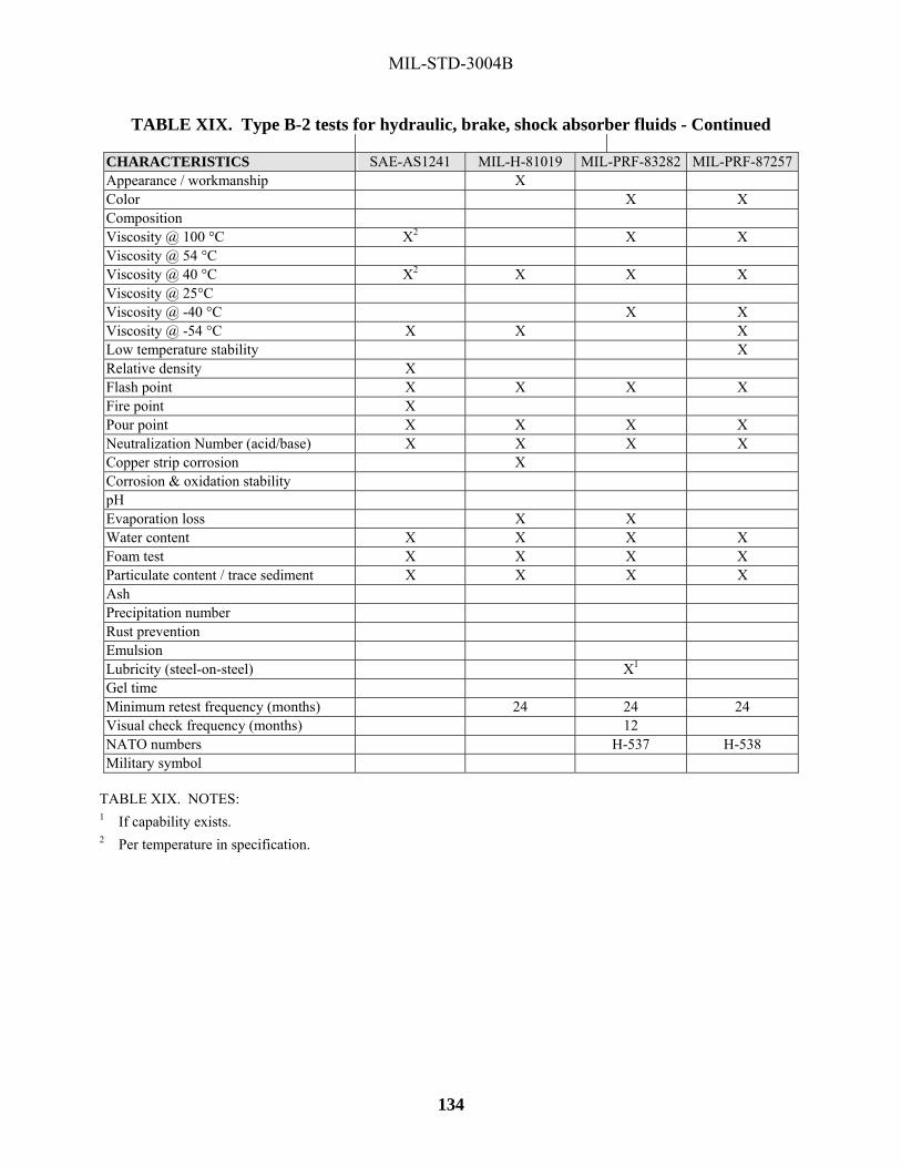
MIL-STD-3004B
134
TABLE XIX. Type B-2 tests for hydraulic, brake, shock absorber fluids - Continued CHARACTERISTICS SAE-AS1241 MIL-H-81019 MIL-PRF-83282 MIL-PRF-87257Appearance / workmanship X Color X X Composition Viscosity @ 100 °C X2 X X Viscosity @ 54 °C Viscosity @ 40 °C X2 X X X Viscosity @ 25°C Viscosity @ -40 °C X X Viscosity @ -54 °C X X X Low temperature stability X Relative density X Flash point X X X X Fire point X Pour point X X X X Neutralization Number (acid/base) X X X X Copper strip corrosion X Corrosion & oxidation stability pH Evaporation loss X X Water content X X X X Foam test X X X X Particulate content / trace sediment X X X X Ash Precipitation number Rust prevention Emulsion Lubricity (steel-on-steel) X1 Gel time Minimum retest frequency (months) 24 24 24 Visual check frequency (months) 12 NATO numbers H-537 H-538 Military symbol
TABLE XIX. NOTES: 1 If capability exists. 2 Per temperature in specification.

MIL-STD-3004B
135
TABLE XX. Type B-2 tests for lubricants, (including solid film) SPECIFICATION CHARACTERISTICS MIL-PRF-3572 MIL-L-23398 MIL-L-24131 MIL-L-24478 Appearance / workmanship X X Color Odor X Viscosity @ 100 °C X1 Viscosity @ 40 °C Viscosity @ 0 °C X1 Viscosity @ -54 °C Boiling point Flash point X Pour point X Density / relative density Composition Oil content Particle size X X Solids content X X X Ash X X Adhesion X Thermal stability X Endurance life X Load carrying capacity Minimum retest frequency (months)
24 12 12 12
Visual check frequency (months) 6 12 NATO numbers S-749
TABLE XX. NOTES: 1 Per temperature in specification.

MIL-STD-3004B
136
TABLE XX. Type B-2 tests for lubricants, (including solid film) - Continued SPECIFICATION CHARACTERISTICS DOD-L-25681 MIL-L-45983 MIL-PRF-46010 MIL-PRF-46147 Appearance / workmanship X Color Odor Viscosity @ 100 °C X Viscosity @ 40 °C X Viscosity @ 0 °C Viscosity @ -54 °C Boiling point Flash point X Pour point Density / relative density Composition X Oil content Particle size Solids content Ash Adhesion Thermal stability Endurance life Load carrying capacity Minimum retest frequency (months)
24 See note 1 Discard 6 months from date of manu.
See note 1
Visual check frequency (months) NATO numbers S-1735
TABLE XX. NOTES: 1 Discard 12 months from date of manufacture.

MIL-STD-3004B
137
TABLE XX. Type B-2 tests for lubricants, (including solid film) - Continued SPECIFICATION CHARACTERISTICS A-A-59004 MIL-PRF-63460 MIL-PRF-81329 SAE AS 87132 Appearance / workmanship X X X Color Odor Viscosity @ 100 °C Viscosity @ 40 °C) Viscosity @ 0 °C Viscosity @ -54 °C X Boiling point Flash point X Pour point X Density / relative density Composition X Oil content X Particle size Solids content Ash Adhesion X Thermal stability X Endurance life X Load carrying capacity X1 Minimum retest frequency (months)
12 36 12 36
Visual check frequency (months) 6 NATO numbers S-758 S-1737
TABLE XX. NOTES: 1 If capability exists.

MIL-STD-3004B
138
TABLE XX. Type B-2 tests for lubricants, (including solid film) - Continued SPECIFICATIONCHARACTERISTICS MIL-L-871772 Appearance / workmanship X Color Odor Viscosity @ 100 °C Viscosity @ 40 °C) Viscosity @ 0 °C Viscosity @ -54 °C Boiling point Flash point X Pour point Density / relative density Composition Oil content Particle size Solids content Ash Adhesion Thermal stability Endurance life Load carrying capacity X1 Minimum retest frequency (months)
24
Visual check frequency (months) NATO numbers
TABLE XX. NOTES: 1 If capability exists. 2 Also, dielectric strength.

MIL-STD-3004B
139
TABLE XXI. Type B-2 tests for waxes SPECIFICATION CHARACTERISTICS C-T-91 MIL-W-10885 MIL-W-12062 MIL-W-12598 Appearance / workmanship X X X Odor X Color Melting point / solidification point X X Softening point X X Penetration X X X Viscosity @ 100 °C X X Oil content X Flash point X X Relative density X X X Ash X X Water content X Neutralization Number (acid/base) X X Saponification number X X Volatile matter X Minimum retest frequency (Months)
48 36 36 36
Visual check frequency (months) NATO numbers

MIL-STD-3004B
140
TABLE XXI. Type B-2 tests for waxes - Continued SPECIFICATION CHARACTERISTICS MIL-W-13945 MIL-W-20553 A-A-50178 Appearance / workmanship X Odor X X Color X Melting point / solidification point X X Softening point X Penetration X X Viscosity @ 100 °C X X Oil content X X Flash point X X Relative density Ash Water content Neutralization Number (acid/base) X X Saponification number X Volatile matter Minimum retest frequency (Months)
36 36 36
Visual check frequency (months) NATO numbers
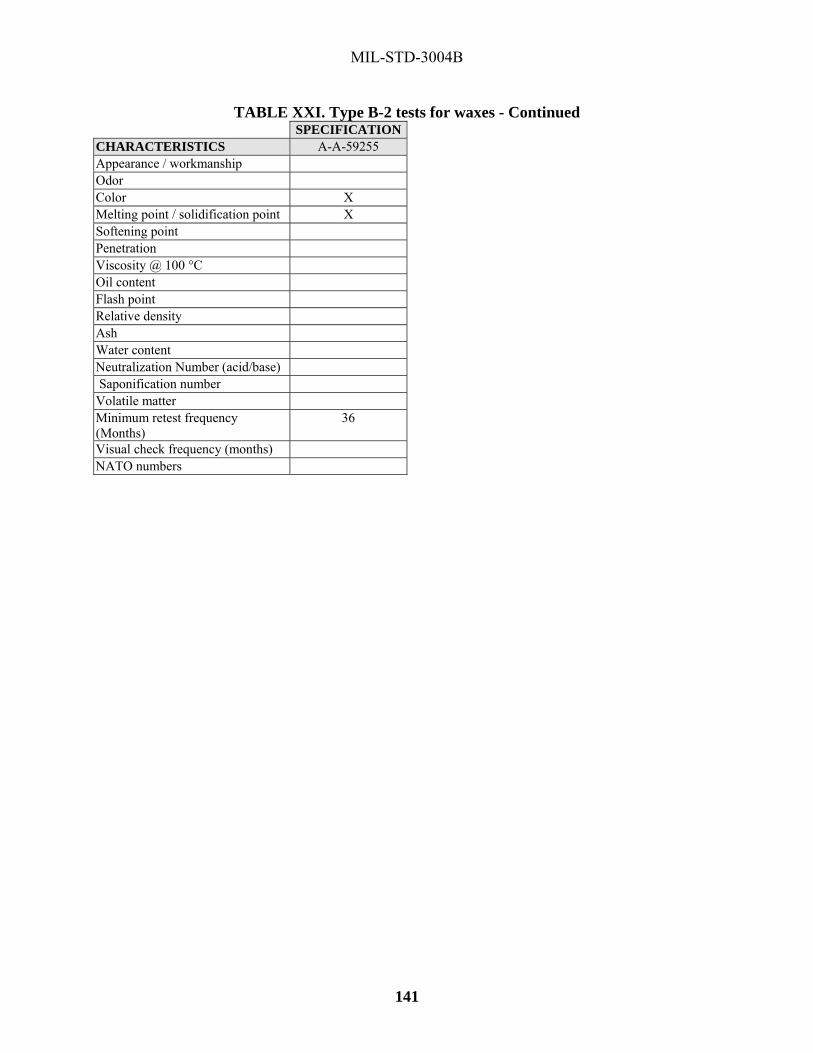
MIL-STD-3004B
141
TABLE XXI. Type B-2 tests for waxes - Continued SPECIFICATIONCHARACTERISTICS A-A-59255 Appearance / workmanship Odor Color X Melting point / solidification point X Softening point Penetration Viscosity @ 100 °C Oil content Flash point Relative density Ash Water content Neutralization Number (acid/base) Saponification number Volatile matter Minimum retest frequency (Months)
36
Visual check frequency (months) NATO numbers

MIL-STD-3004B
142
TABLE XXII. Type B-2 tests for misc. products (specialty, cutting, anti-seizing, etc.) etc.) SPECIFICATION CHARACTERISTICS O-M-232 SS-G-659 TT-I-735 VV-C-846 Appearance / workmanship X X X X Viscosity @ 100 °C Viscosity @ 54 °C Viscosity @ 40 °C Viscosity @ -40 °C Viscosity @ -54 °C Relative density X X Distillation Flash point X Fire point Pour point X Worked penetration Melting point Protection Corrosion Neutralization Number (acid/base) Acidity X X Lead corrosion pH X Stability Evaporation / bleed Residue on evaporation X Ash Precipitation number Foaming Emulsification properties X Contamination / sediment Water content X Dielectric strength Film appearance Drying Rate Particle size (fineness) X Minimum retest frequency (months)
24 48 48 36
Visual check frequency (months) 12 12 12 12 NATO numbers S-747 S-732 S-737 O-214

MIL-STD-3004B
143
TABLE XXII. Type B-2 tests for miscellaneous products (specialty, cutting, anti-seizing, etc.) - Continued. CHARACTERISTICS SAE-AMS 2518 ASTM D 3487 MIL-C-4339 Appearance / workmanship X X Viscosity @ 100 °C Viscosity @ 54 °C Viscosity @ 40 °C X Viscosity @ -40 °C Viscosity @ -54 °C Relative density X Distillation Flash point X Fire point Pour point X Worked penetration X Melting point Protection Corrosion X Neutralization Number (acid/base) X Acidity Lead corrosion pH X Stability Evaporation loss/ bleed X Residue on evaporation Ash Precipitation number Foaming Emulsification properties X Contamination / sediment Water content X Dielectric strength X Film appearance Drying Rate Particle size (fineness) Minimum retest frequency (months)
36 24 48
Visual check frequency (months) 12 NATO numbers S-720 C-630 1Per temperature in specification.

MIL-STD-3004B
144
TABLE XXII. Type B-2 tests for miscellaneous products (specialty, cutting, anti-seizing, etc.) - Continued.
SPECIFICATION CHARACTERISTICS MIL-DTL-520 MIL-C-6529 SAE AMS-M-
7866 MIL-PRF-8188
Appearance / workmanship X X X X Viscosity @ 100 °C X Viscosity @ 54 °C Viscosity @ 40 °C X1 Viscosity @ -40 °C Viscosity @ -54 °C Relative density Distillation X Flash point X X Fire point Pour point Worked penetration Melting point Protection X X2 Corrosion X X Neutralization Number (acid/base) Acidity Lead corrosion X pH Stability X Evaporation / bleed Residue on evaporation Ash Precipitation number X Foaming Emulsification properties Contamination / sediment Water content Dielectric strength Film appearance Drying Rate Particle size (fineness) X Minimum retest frequency (months)
48 36 36 36
Visual check frequency (months) 12 NATO numbers S-712 C-608, C-609 C-638 TABLE XXII. NOTES: 1Per temperature in specification. 2If capability exists.

MIL-STD-3004B
145
TABLE XXII. Type B-2 tests for miscellaneous products (specialty, cutting, anti-seizing, etc.) - Continued.
SPECIFICATION CHARACTERISTICS SAE-AMS1424 SAE-AS8660 MIL-C-11796 MIL-PRF-12070 Appearance / workmanship X X X X Viscosity @ 100 °C X Viscosity @ 54 °C Viscosity @ 40 °C Viscosity @ -40 °C Viscosity @ -54 °C Relative density X Distillation Flash point X Fire point Pour point Worked penetration X X Melting point X Protection Corrosion X X Neutralization Number (acid/base) Acidity Lead corrosion pH X Stability X Evaporation / bleed X Residue on evaporation Ash Precipitation number Foaming Emulsification properties Contamination / sediment Water content Dielectric strength X1 Film appearance Drying Rate Particle size (fineness) Minimum retest frequency (months)
48 36 36 12
Visual check frequency (months) 24 12 NATO numbers S-742 S-736 C-627, C-633 F-60, F-62 TABLE XXII. NOTES: 1If capability exists.

MIL-STD-3004B
146
TABLE XXII. Type B-2 tests for miscellaneous products (specialty, cutting, anti-seizing, etc.) - Continued. SPECIFICATION CHARACTERISTICS MIL-PRF-16173 MIL-T-17128 SAE AM 1428 MIL-PRF-46002 Appearance / workmanship X X X X Viscosity @ 100 °C X X Viscosity @ 54 °C Viscosity @ 40 °C X X Viscosity @ -40 °C Viscosity @ -54 °C Relative density X X Distillation Flash point X Fire point Pour point X X Worked penetration Melting point Protection Corrosion X X Neutralization Number (acid/base) X Acidity Lead corrosion pH X Stability X Evaporation / bleed X Residue on evaporation Ash X Precipitation number X Foaming Emulsification properties Contamination / sediment Water content Dielectric strength Film appearance X Drying Rate X Particle size (fineness) Minimum retest frequency (months)
36 36 24 24
Visual check frequency (months) NATO numbers C-620, C-632 S-1719/S-1723

MIL-STD-3004B
147
TABLE XXII. Type B-2 tests for miscellaneous products (specialty, cutting, anti-seizing, etc.) - Continued. CHARACTERISTICS A-A-50493 A-A-51693 A-A-52624 Appearance / workmanship X X Viscosity @ 100 °C Viscosity @ 54 °C Viscosity @ 40 °C X Viscosity @ -40 °C Viscosity @ -54 °C Relative density Distillation Flash point X Fire point Pour point Worked penetration Melting point Protection Corrosion X Neutralization Number (acid/base) Acidity Lead corrosion pH Stability Evaporation / bleed Residue on evaporation Ash Precipitation number Foaming Emulsification properties Contamination / sediment Water content X Dielectric strength Film appearance Drying Rate Particle size (fineness) Surface and interface tension X Minimum retest frequency (months)
36
Visual check frequency (months) 36 36 NATO numbers

MIL-STD-3004B
148
TABLE XXII. Type B-2 tests for miscellaneous products (specialty, cutting, anti-seizing, etc.) - Continued. SPECIFICATION CHARACTERISTICS A-A-58092 A-A-59197 MIL-DTL-854702 Appearance / workmanship X X X Viscosity @ 100 °C Viscosity @ 54 °C Viscosity @ 40 °C X1 Viscosity @ -40 °C Viscosity @ -54 °C Relative density X Distillation Flash point X Fire point Pour point X Worked penetration Melting point Protection Corrosion Neutralization Number (acid/base) X Acidity X Lead corrosion pH X Stability Evaporation / bleed Residue on evaporation Ash Precipitation number Foaming Emulsification properties Contamination / sediment Water content X Dielectric strength Film appearance Drying Rate Particle size (fineness) Minimum retest frequency (months)
36 12
Visual check frequency (months) 123 NATO numbers S-1736 S-1745
TABLE XXII. NOTES: 1Per temperature in specification. 2 Also, color. 3 Check container for damage.

MIL-STD-3004B
149
TABLE XXII. Type B-2 tests for miscellaneous products (specialty, cutting, anti-seizing, etc.) - Continued. SPECIFICATIONCHARACTERISTICS MIL-PRF-87252 Appearance / workmanship X Viscosity @ 100 °C X Viscosity @ 54 °C Viscosity @ 40 °C X Viscosity @ -40 °C X Viscosity @ -54 °C X Relative density Distillation Flash point X Fire point X Pour point Worked penetration Melting point Protection Corrosion X Neutralization Number (acid/base) X Acidity Lead corrosion pH Stability Evaporation / bleed Residue on evaporation Ash Precipitation number Foaming Emulsification properties Contamination / sediment X Water content X Dielectric strength X Film appearance Drying Rate Particle size (fineness) Minimum retest frequency (months)
24
Visual check frequency (months) NATO numbers S-1748

MIL-STD-3004B
150
TABLE XXIII. Conversion chart for tank cars and tank trucks1
PRODUCT TO BE LOADED LAST PRODUCT CARRIED
Gasolines MOGAS/ E-85 AVGAS JP-4
Jet Fuels: Jet A/A-1, JP-8, JP-5, TS-1, DFW
2Jet Fuel: JPTS
Diesel Fuels: F-76, DL1, DL2, DF1, DF2, 1-D, 2-D, FS1, FS2, B20
FSII7 Lubricating Oils
Gasolines: MOGAS/E-85 AVGAS JP-4
Drain/ Empty
Steam Dry3 Steam Dry Steam Dry
Steam Dry
Steam Dry
Jet Fuels: Jet A/A-1, JP-8, JP-5 TS-1, DFW,
Drain/ Empty4
Drain/Empty4 Steam Dry4 Drain/Empty5 Steam Dry4
Steam Dry4
Jet Fuel: JPTS
Drain/ Empty
Drain/ Empty
Drain/ Empty
Drain/Empty Steam Dry
Steam Dry
Petroleum Solvent or Paint Thinner
Steam Dry Drain/Empty Steam Dry Steam Dry Steam Dry
Steam Dry
Diesel Fuels: F-76, DL1, DL2, DF1, DF2, 1-D, 2-D, FS1, FS2, B20
Steam Dry4 Drain/Empty4 Steam Dry4 Drain/Empty5 Steam Dry4
Steam Dry4
Lubricating Oils NO LOAD NO LOAD NO LOAD Steam Dry
NO LOAD
Drain/ Empty6
ASTM D975 No.4D, FS4, FS5, FS6, IFOs
NO LOAD
NO LOAD NO LOAD NO LOAD NO LOAD
NO LOAD
Naphtha Drain/ Empty
Steam Dry Steam Dry Steam Dry Steam Dry
Steam Dry
TABLE XXIII. NOTES:
1 Individual Services provide specific guidance for conversion of refueling equipment which exclusively handles Service petroleum products, e.g.: Air Force guidance is contained in T.O. 42B-1-1, Table 3-1.
2 To be loaded only in aluminum, stainless steel equipment or equipment lined with an approved epoxy coating. If equipment is coated, clean with hot fresh water not exceeding 58 °C (136 oF) and dry thoroughly.
3 For an additional policy on steam cleaning for JP-8 see 5.3.1.2. 4 If previous cargo contained dye marker, all traces of color must be removed. 5 If product to be loaded does not contain dye, then the vehicle not contain any traces of dye prior to loading. 6 Applicable only when loading compatible oils; otherwise, steam and dry. 7 For previous cargoes not listed, contact DESC-BP for acceptability/cleaning procedures.
TABLE XXIII. GENERAL INSTRUCTIONS:
1. Equipment carrying lubricating oil be dry and free from loose rust, scale, and dirt. Equipment carrying other products be substantially free from loose rust, scale and dirt.
2. Saran lined equipment should not be steam cleaned; water wash should suffice.

MIL-STD-3004B
151
TABLE XXIII. Conversion chart for tank cars and tank truck. Continued: TABLE XXIII. GENERAL INSTRUCTIONS. Continued:
3. Petroleum products not be loaded into the transportation equipment whose previous cargo was caustic, acid, or chlorinated solvents.
4. Tank trucks in liquid fertilizer service not load aviation turbine fuels directly, but carry out at least two loads of commercial gasoline prior to the aviation turbine fuel load.
5. Conversion of Government-owned tank cars from liquid fertilizer service to aviation turbine fuel service only be done when no other alternative exists. Tank cars being converted from liquid fertilizer service to a petroleum product be adequately cleaned to remove all traces of liquid fertilizer. At a minimum the equipment must be steam cleaned; dried and be free from loose rust, scale, and dirt. After cleaning, equipment with unlined compartments should have its compartments lined with an approved coating at this time. Conveyances not be released from origin loading point until loaded conveyance is sampled after a minimum wait of 24 hours after loading. The sample be tested to Type B-2 tests plus Thermal Stability Test (if required by the product specification). After type B-2 tests indicate compliance with specification requirements, the conveyance can be released pending results of Thermal Stability tests. The conveyance not be unloaded until origin car notifies the destination that the Thermal Stability test (when required) has passed. When the above condition applies, the DD-250 be so noted.

MIL-STD-3004B
152
TABLE XXIV. Minimum requirements for the preparation of tanker cargo tanks
PRODUCT TO BE LOADED
LAST PRODUCT CARRIED
Jet fuels: JP-4, JET B Gasolines: Mogas, Avgas
Jet fuels: JP-8 Jet A-1 DFW
Jet Fuel: JP-5
Jet Fuel: JPTS,
Diesel Fuels: F-76, DF-1, DF-2, DL1, DL2, DS-1, DS-2 ASTM D975 (No 1, 2)
ASTM D975 (N0 4D), FS 4, 5, 6, IFOs
Jet fuels: JP-4, JET B Gasolines: Mogas, Avgas
A
B, A
B, A
See
Note 2
B, A
A
Jet fuels: Jet A, Jet A-1 JP-8 DFW
A
A
B, A
See
Note 2
A
A
Jet Fuel: JP-5
A
A
A
See Note 2
A
A
Jet Fuel: JPTS
A
A
B, A
See Note 2
A
A
Diesel Fuels: F-76, DF-1, DF-2, DL1, DL2, DS-1, DS-2 ASTM D975 (No 1, 2)
C, A
C, A
C, A
NO LOAD
A
A
ASTM D975 (N0 4D), FS 4, 5, 6, IFOs
NO
LOAD
NO
LOAD
NO
LOAD
NO
LOAD
D, A
A
Crude3
NO LOAD
NO LOAD
NO LOAD
NO LOAD
D, A
A
Lube Oils NO LOAD
NO LOAD
NO LOAD
NO LOAD
D,A
A
TABLE XXIV. LEGEND:
A. All cargo lines be dropped, tanks stripped, ballast residue removed. B. All cargo and vent lines be drained of previous product and flushed with cold water. Cargo tanks be
thoroughly machine washed using cold water. Cargo tanks must be free of water, loose rust, sludge, mud, slit, etc.
C. The same as for “B,” except that hot water be used instead of cold. If tank interiors are coated, water temperature should not exceed 58 °C (136 oF).
D. Cargo tanks and systems be processed in accordance with the instructions contained in MIL-HDBK-291, Cargo Tank Cleaning.

MIL-STD-3004B
153
TABLE XXIV. Minimum requirements for the preparation of tanker cargo tanks Continued
TABLE XXIV. NOTES: 1 This table is included as a guide only. Requirements for tanker cleaning are determined by MSC vessel
cleaning policy (See 5.1.1.4). Contact MSC for tank cleaning requirements for any product not listed in TABLE XXIV.
2 Special tank preparations and cargo handling is required for JPTS, to prevent contamination. Tanks used for loading must be coated with an approved epoxy. Coating must be adherent: no flaking, peeling, or blistering. It is mandatory that JPTS be loaded in tanks in which the last product carried was JP-5, JP-4, kerosene-based fuels (JP-8, Jet A, etc.), non-aromatic solvent, unleaded gasoline, or arctic diesel. Prior to loading JPTS, tank cleaning requirements are: tanks must be machine washed with hot water, if cleaning chemical and/or salt water is used, the final wash must be with fresh water. Tank bottoms, interior bulk heads, and internals must be completely free of sediment, scale, and other contaminants. Tanks must be dry and all liquids completely removed from the tank’s lines after cleaning, must be flushed with fresh water, drained and free all water. Loading and unloading system must be completely isolated. This be accomplished by completely separate piping systems or by use of blinds. Valves not be depended on to effect isolation. No common lines be used. Steam smothering lines should have at least two valves that can be sealed from the main line to the tanks, or a blind installed that can be readily removed. Each tank have its own individual vent. If ship has a common vent system, tanks used for JPTS must be isolated from balance of the vent system.
3 There are no circumstances were a crude carrier is capable of cleaning tanks, pumps and lines sufficiently to load an aviation fuel immediately after a crude cargo. Crude carriers converted to a distillate diesel, aviation fuel or naphtha based fuel must carrier five cargoes of a commercial like product without a quality incident.

MIL-STD-3004B
154
TABLE XXV. Minimum requirements for the preparation of barge cargo tanks1
PRODUCT TO BE LOADED LAST PRODUCT CARRIED
Leaded gasoline, aviation
Gasoline, automotive
Turbine fuel, aviation,
kerosene type F-34, F-35,
F-44
Diesel fuel oil - distillate
Diesel fuel oil -residual
Lube oil
Leaded Gasoline, Aviation
A A B B B B
Gasoline, Automotive
A A B B B B
Turbine fuel, aviation, kerosene TYPE, F-34, F-35, F-44
A A A A A E
Diesel fuel oil - distillate
C C A A A E
Diesel fuel oil - residual
NO LOAD NO LOAD NO LOAD D A E
Lube oils
NO LOAD NO LOAD NO LOAD D A E
TABLE XXV. LEGEND: A. Drop lines and strip tanks.
B. All cargo and vent lines be drained of previous product and flushed with cold water. Cargo tanks be thoroughly machine washed using cold water. Tanks be gas freed.
C. The same as for Paragraph B., above, except that hot water be used instead of cold water. D. The same as for Paragraph C above. In addition tanks and lines be flushed with product to be loaded and
examined to confirm meeting product specification. Process be repeated as necessary until passing results are obtained.
E. Cargo tanks and systems must be cleaned in such a manner as remove all rust, scale, sediment, and all traces of previous cargo and water
TABLE XXV. NOTES: 1 In all cases, cargo tanks must be free of water, loose rust, sludge, mud, silt, ballast residue, etc.

MIL-STD-3004B
155
TABLE XXVI. Segregation of product movements via multiproduct pipelines, head product
The following pertains to segregated product as it is moved in the bulk commercial pipeline system. As a rule, Government-owned products are moved via commercial multi-product pipelines from refineries to DFSPs, or from DFSP to DFSP. Contract or tariff agreements with the commercial pipeline company outline the type of interface cut (heart-cut or mid-point cut) that be used on Government product. When Government product is delivered to a customer by pipeline, it is usually through a dedicated system from the DFSP. In those situations where product is delivered directly off of a commercial multi-product pipeline to a using customer, heart-cuts should be used HEAD/TAIL PRODUCT GOVERNMENT PRODUCT BEING MOVED
GASOLINE DIESEL1 DYED DIESEL JP-5 JP-8
GASOLINE M H M M DIESEL H H M M DYED DIESEL N/A N/A N/A N/A N/A JP-5 H M H M M JP-8 H M H M M TABLE XXVI. LEGEND H = HEART-CUT M = MID-POINT CUT 1 Ultra Low Sulfur Diesel (ULSD) may require a little more ULSD be cut into military aviation fuels in order to
protect the sulfur content of the ULSD. The procedures be agreed ahead of time with the carrier/contractor and be agreeable to all. Information on the total sulfur content of the typical military aviation fuel be used as the basis for the formation of he cutting procedures agreed.

MIL-STD-3004B
156
TABLE XXVII. Contamination tables TYPE CONTAMINANTS APPEARANCE CHARACTERISTICS EFFECTS ON AIRCRAFT A. WATER (1) Dissolved Water Not Visible. Freshwater only. Precipitates out as
cloud when fuel is cooled. None unless precipitated out by cooling of fuel. Can then cause ice to form on low-pressure fuel filters.
(2) Free Water Light cloud. Heavy cloud. Droplets adhering to sides of bottle. Gross amounts settled in bottom.
Free water may be saltwater or fresh water. Cloudy usually indicates water-in-fuel emulsion.
Icing of fuel systems, usually low-pressure fuel filters; erratic fuel gage readings; gross amounts of water can cause flameouts; saltwater cause corrosion of fuel system components.
B. SEDIMENT (1) Rust Red or black
powder, rouge or grains. May appear as dye-like material in fuel.
Red rust (Fe2O3) nonmagnetic. Black rust (Fe3O4) magnetic. Rust generally comprises the major constituent of total sediment.
cause sticking, sluggish or general malfunction of fuel controls, flow dividers, pumps, nozzles, etc.
(2) Sand or dust Crystalline, granular or glasslike.
Usually present and occasionally constitutes major constituent of total sediment.
cause sticking, sluggish or general malfunction of fuel controls, flow dividers, pumps, nozzles, etc.
(3) Aluminum or magnesium
White or gray powder or paste.
Sometimes very sticky or gelatinous when wet with water. Normally present and can constitute the major constituent of total sediment.
cause sticking, sluggish or general malfunction of fuel controls, flow dividers, pumps, nozzles, etc.
(4) Fibers A fiber is defined as a particle having a length to diameter ratio of 20 to 1 or more and having a length of 100 microns or more.
cause sticking, sluggish or general malfunction of fuel controls, flow dividers, pumps, nozzles, etc.

MIL-STD-3004B
157
Table XXVII. Contamination tables - Continued TYPE CONTAMINANTS APPEARANCE CHARACTERISTICS EFFECTS ON AIRCRAFT C. EMULSIONS (1) Water in fuel emulsions Light cloud. Heavy
Cloud. Finely divided drops of water in fuel. Same as free water cloud. settle to bottom in minutes, hours, or weeks, depending on nature of emulsion.
Same as free water.
(2) Fuel in water or “inverse” emulsions
Reddish, grayish, or blackish. Sticky material variously described as gelatinous, gummy, or “mayonnaise-like.”
Fine divided drops of fuel in water. Contains rust which stabilizes or “firms” the emulsion. adhere to most materials normally in contact with fuels. Usually present in “globules” or stringy, fibrous-like material in clear or cloudy fuel. stand from days to months without separating. This material contains 50-70% water, a small amount of fine rust, and 30-50% fuel.
Same as free water and sediment, only more drastic. quickly cause filter plugging or erratic readings in fuel quantity probes.
D. MICROBIOLOGICAL GROWTH
Brown, gray, or black. Stringy or fibrous
Usually found with other contaminants in the fuel. Typically found at the fuel water interface but can also form films on the tanks surfaces. Develops only when free water is present.
Fouls fuel quantity probes, sticks flow dividers, and makes fuel controls sluggish.
E. MISCELLANEOUS (1) Interface material Lacy bubbles at
interface between fuel and water. Sometimes resembles jellyfish.
Extremely complicated chemically. Occurs only when free water is present.
Effects due to presence of free water.
(2) Air Bubbles Cloud in fuel. Disperses upward within a few seconds None. (3) Media Migration Thin to Thickened,
light to dark brown, molasses type material
Found in filter separators utilizing water absorbing (super absorbent polymer based), filter monitor fuse filters. Polymer may migrate downstream of the filter separator all the way to the aircraft fuel tank.
Capable of blocking the engine fuel filters. May promote microbial growth within the wing tank.
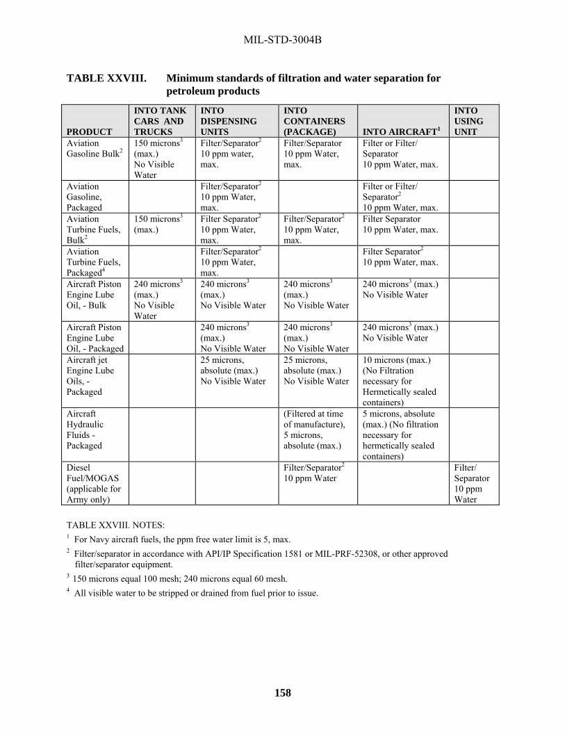
MIL-STD-3004B
158
TABLE XXVIII. Minimum standards of filtration and water separation for petroleum products
PRODUCT
INTO TANK CARS AND TRUCKS
INTO DISPENSING UNITS
INTO CONTAINERS (PACKAGE)
INTO AIRCRAFT1
INTO USING UNIT
Aviation Gasoline Bulk2
150 microns3 (max.) No Visible Water
Filter/Separator2 10 ppm water, max.
Filter/Separator 10 ppm Water, max.
Filter or Filter/ Separator 10 ppm Water, max.
Aviation Gasoline, Packaged
Filter/Separator2
10 ppm Water, max.
Filter or Filter/ Separator2 10 ppm Water, max.
Aviation Turbine Fuels, Bulk2
150 microns3 (max.)
Filter Separator2 10 ppm Water, max.
Filter/Separator2 10 ppm Water, max.
Filter Separator 10 ppm Water, max.
Aviation Turbine Fuels, Packaged4
Filter/Separator2 10 ppm Water, max.
Filter Separator2
10 ppm Water, max.
Aircraft Piston Engine Lube Oil, - Bulk
240 microns3 (max.) No Visible Water
240 microns3 (max.) No Visible Water
240 microns3 (max.) No Visible Water
240 microns3 (max.) No Visible Water
Aircraft Piston Engine Lube Oil, - Packaged
240 microns3 (max.) No Visible Water
240 microns3 (max.) No Visible Water
240 microns3 (max.) No Visible Water
Aircraft jet Engine Lube Oils, - Packaged
25 microns, absolute (max.) No Visible Water
25 microns, absolute (max.) No Visible Water
10 microns (max.) (No Filtration necessary for Hermetically sealed containers)
Aircraft Hydraulic Fluids - Packaged
(Filtered at time of manufacture), 5 microns, absolute (max.)
5 microns, absolute (max.) (No filtration necessary for hermetically sealed containers)
Diesel Fuel/MOGAS (applicable for Army only)
Filter/Separator2 10 ppm Water
Filter/ Separator 10 ppm Water
TABLE XXVIII. NOTES: 1 For Navy aircraft fuels, the ppm free water limit is 5, max. 2 Filter/separator in accordance with API/IP Specification 1581 or MIL-PRF-52308, or other approved
filter/separator equipment. 3 150 microns equal 100 mesh; 240 microns equal 60 mesh. 4 All visible water to be stripped or drained from fuel prior to issue.

MIL-STD-3004B
159
THIS PAGE INTENTIONALLY BLANK

MIL-STD-3004B
160
METHOD 1000
TEST FOR EFFECTIVENESS OF PIPELINE RUST INHIBITORS 1. Scope. This method outlines the procedures for determining the effectiveness of rust inhibitors in product moving through pipeline by a steel rod (coupon). 2. Apparatus. 2.1 One SAE-1020 steel rod. Rods sold as SAE-1020 may vary in rusting tendency. The rods used in this test should produce a rating of R-7 in aviation gasoline which does not contain a rust inhibitor. 2.2 Same apparatus as used in ASTM D665, except the oil bath and related heating equipment are not required. 3. Procedure. 3.1 Polish the steel rod in accordance with ASTM D665. 3.2 Pour 350 mL of the product into a beaker. Cover the beaker and insert stirrer and polished steel rod. Stir for 10 minutes to ensure wetting the rod. 3.3 Remove 50 mL of the product with a pipette and add 30 mL of synthetic sea water prepared in accordance with ASTM D665. Continue stirring for one hour at room temperature. 3.4 Stop stirring, remove steel rod and examine. 4. Report. 4.1 Inspect the steel rod for rust and rate using the following chart:
APPEARANCE OF ROD RATING DESIGNATION Free of Rust Passes R-1 Trace of Rust, few spots Passes R-2 Less than 5% surface rusted Barely Passes R-3 5-50% surface rusted Does not Pass R-4 50-90% surface rusted Does not Pass R-5 Surface covered with light Rust Does not Pass R-6 Surface covered with heavy Rust Does not Pass R-7

MIL-STD-3004B
161
THIS PAGE INTENTIONALLY BLANK

MIL-STD-3004B
162
METHOD 1010
VISUAL QUALITY SURVEILLANCE TEST
(Clean/Clear and Bright Test) 1. Scope. This appendix outlines the procedures for conducting the visual quality surveillance test. 2. Container. A round, transparent bottle or laboratory beaker from one liter (one quart) to 4 liters (one gallon) in size. Container should be as clean as possible. 3. Procedures. 3.1 Be sure the sampling valve is free of solid contaminants. Flush sampling valve prior to taking of actual sample. 3.2 Draw the sample as rapidly as possible (full flush) rather than permitting the sample to trickle out. Avoid contaminating the sample from outside sources. 3.3 Check for proper color and all forms of visual contamination by swirling the sample so a vortex is formed. All sediment or water that has settled accumulate on the bottom of the bottle directly beneath the vortex. Experience dictate what can be considered excessive sediment. Very fine suspended solids or water render the product hazy. If the examination is questionable, a laboratory analysis be made to verify the quantity of contaminant.

MIL-STD-3004B
163
THIS PAGE INTENTIONALLY BLANK

MIL-STD-3004B
164
METHOD 1020
TEST FOR SULFIDES IN WATER
1. Scope. This method describes a procedure for determining the presence of hydrogen sulfide that sometimes forms as a result of bacterial action of the sulfates contained in water bottoms in fuel storage tanks. 2. Apparatus. 250 mL conical flask. 3. Materials. 3.1 Dilute (10%) ACS grade, sulfuric or hydrochloric acid. 3.2 Lead acetate paper. 4. Samples. Representative water samples from storage tank bottoms must be taken in a glass bottle. In some cases it be necessary to take the water sample in a Bacon bomb sampler. Samples so taken always be transferred to a glass bottle. To preclude oxidation by air, the filled bottle must be capped immediately. The sample should be tested as soon as possible after sampling to minimize possible changes in the composition of materials in the water. 5. Procedure. 5.1 The sample must be shaken thoroughly just prior to performing the test to make certain any sediment present is included in the portion of the sample to be tested. 5.2 Transfer 100 mL of the shaken sample into a 250 mL conical flask. Add 20 mL of dilute (10%) ACS grade, sulfuric or hydrochloric acid to the flask. Immediately place a piece of lead acetate paper folded into a V shape in the neck of the flask. Bring the water to a boil and continue to gently boil for three or four minutes. Observe the color change of the paper.
6. Report. Report negative for sulfides if there is no color change in the lead acetate paper. Report positive for sulfides if the color of the lead acetate paper changes. The color may vary from a light brown to a black.

MIL-STD-3004B
165
THIS PAGE INTENTIONALLY BLANK

MIL-STD-3004B
166
METHOD 1030
DETERMINATION OF SMALL AMOUNTS OF LEAD IN FUELS
1. Scope. The method covers the determination of lead alkyls content of fuel in the range of 0.001g to 0.020 g of lead per liter. Note: This method is not applicable to fuels containing metal salts other than lead that are capable of producing colored sulfides. 2. Summary. The lead alkyl is extracted by refluxing the unconverted to lead chloride that is then measured by a colorimetric method, using sodium sulfide. The brown color is compared to the color obtained by adding a known quantity of lead nitrate to a sodium sulfide solution. 3. Apparatus. Note: All glass must have a low lead content. 3.1 Extraction apparatus. 3.2 Beakers - in Pyrex glass, 250 mL. 3.3 Burette - 5 mL, graduated in 0.05 mL. 4. Reagents. 4.1 Hydrochloric acid (relative density = 1.19) 4.2 Sodium sulfide solution, 20g in one liter of distilled water. 4.3 Lead nitrate. Solution-dry lead nitrate crystals for one hour in an oven at 110 °C. Dissolve 0.8g of the dry lead nitrate in distilled water and make up to one liter with distilled water. Discard the solution if it is more than two months old. 4.4 Ammonium hydroxide solution. Prepared by mixing 30 parts of ammonium hydroxide (relative density = 0.925) with 70 parts of distilled water. 5. Procedure. 5.1 Thoroughly clean all glassware. 5.2 Transfer 50 mL of the filtered sample to the flask, add 15 mL of HCl and heat until boiling. When reflux commences, regulate the heat to stop bumping in the flask and to avoid flooding the condenser. After 10 minutes of refluxing, stop heating to allow the sample to cool for a few minutes and then drain the acid layer into a 250 mL beaker. Add 15 mL of distilled water to the flask and reflux the mixture for 5 minutes, using full heat. Cool for a few minutes and drain the water layer into the beaker already containing the acid layer.

MIL-STD-3004B
167
METHOD 1030 - Continued 5.3 Add 30 mL of water to the beaker. Neutralize with the ammonium hydroxide solution to change the color of indicator paper (pH 7). Make up to 100mL with distilled water. 5.4 Fill the burette with the lead nitrate solution. 5.5 Place 100 mL of distilled water in a second beaker; the volume must be identical to that in the first beaker. 5.6 Add 10 mL of sodium sulfide solution to each beaker. Swirl gently. A brown color develop in the test solution. Match this color by addition of lead nitrate solution to the second beaker (blank solution). 5.7 The preceding operations must be carried out rapidly to avoid color changes. If less than 0.2 mL or more than 2 mL of lead nitrate solution has been used, the test should be repeated using a suitable volume of sample. Note: Avoid contact between the lead nitrate solution and vapor from the ammonium sulfide. 6. Calculation. 6.1 Calculate the total lead content, as follows:
X = (0.5) * (n) / V X = Lead content in g/L
n = mL of lead nitrate solution used V = volume of the sample in mL 7. Precision. The reproducibility of the method is 0.001 g/L for lead contents under 0.020 g/L. 8. Referee. IP-224 Test Method be used as a referee method.

MIL-STD-3004B
168
METHOD 1040
DETECTION OF HEAVY HYDROCARBON CONTAMINATION IN AVIATION GASOLINE
1. Scope. This method of test covers the determination of trace amounts of turbine engine fuel or other heavy hydrocarbon contaminant (JP-4 or heavier) in aviation gasoline. It is intended as a field evaluation method and is not to be used in place of the distillation or other specification test. 2. Definitions. 2.1 Capillary attraction: The attraction of a liquid to a solid, and the accompanying movement of the liquid over the solid as in the movement through a wick. 2.2 Chromatography: The separation of mixtures into their constituents by preferential absorption by a solid such a strip of filter paper. 2.3 Aviation gasoline: Fuels conforming to ASTM D910 having a final boiling point of 170 °C or less. 2.4 Turbine engine fuel: Fuels conforming to MIL-DTL-5624, MIL-DTL-83133 or ASTM D1655 and other fuels having an final boiling point above 238 °C. 3. Outline of Method. Twenty five (25) mL each of a known quality aviation gasoline of the same grade being tested and the fuel of questionable quality is dyed with approximately 0.01 mg of powdered fuel soluble dye in addition to that already contained in the fuel. (Note: liquid dye is not to be used since the solvent show up as contaminant in this test). Nine (9) mL of each of the dyed fuels are placed in separate 10 mL test tubes. The test tubes are mounted in a suitable holder and 0.6 cm (1/4") strips of the #10 filter paper or other absorbent paper 20 cm (8 inches) long are extended to the bottom of the test tubes. After five minutes, the height of the fuel on the paper is noted. If the height of the fuel of questionable quality is 0.6 cm (¼") higher than the fuel of known quality, then contamination should be suspected. 4. Apparatus. 4.1 10 mL test tubes 15 mm x 85 mm. 4.2 20 cm (8-inch) ruler 4.3 Holder (fabricated in accordance with figure 1). 4.4 #40 Whatman filter paper

MIL-STD-3004B
169
METHOD 1040 – Continued 4.5 50 mL beakers.
5. Reagents. 5.1 Dye, fuel soluble blue. 5.2 Reference fuel (aviation gasoline that has been tested for complete specification tests and is maintained in a sealed container). 6. Procedure. 6.1 Measure 25 mL each of reference fuel and sample to be tested into separate 50 mL beakers. Add approximately 0.01 g of blue dye to each beaker and mix thoroughly by swirling. 6.2 Transfer the dyed fuel to separate 10 mL test tubes. Fill the test tube to the top lip. Insert the filled test tubes into the holder. 6.3 Lower a 0.6 cm wide by 20 cm long (or ¼" by 8") long strip of Whatman filter paper into the test tube until it touches the bottom of the tube. Affix the top of the filter paper to the holder in an extended position.6.4 After 5 minutes and 15 minutes, record the heights of the fuels on the two filter papers. 6.5 Contamination is indicated by the height of the fuel on the chromatography strip of the unknown sample versus the height of the referenced fuel on the chromatography strip. A height of 0.6 cm (or ¼") above the referenced fuel would indicate possible contamination. 7. Report. Report the difference in centimeters or inches between the sample and the referenced fuel heights on the chromatographic strip. 8. Precision. Results should not differ by more than 0.3 cm (or 1/8").

MIL-STD-3004B
170
METHOD 1040 – Continued
FIGURE 1. Chromatography strip holder
| 5/8”|
3 1/2”
3”| 5/8”|
3 1/2”
3”
| 5/8”|
3 1/2”
3”

MIL-STD-3004B
171
THIS PAGE INTENTIONALLY BLANK

MIL-STD-3004B
172
METHOD 1050
DETECTION OF NITRATE IGNITION-TYPE IMPROVERS IN DIESEL FUEL
1. Scope. This method of test covers the determination of organic nitrate ester type cetane improver additives used in diesel fuel. It is intended as a screening test for those diesel fuel inspection test procedures that are affected by the presence of cetane improvers, namely ASTM D524, Standard Method of Test for Ramsbottom Carbon Residue of Petroleum Products, and ASTM D976, Standard Method for Calculated Cetane Index of Distillate Fuels. 2. Summary. A diesel fuel sample is saponified in a potassium hydroxide-butanol mixture and then filtered through a glass fiber filter disc. The material remaining on the disc is treated with diphenylamine reagent after drying. The presence of a nitrate ester cetane improver is revealed by the formation of a blue ring and blue/black spot due to oxidation of diphenylamine to intense blue quinoidal compounds by the nitrate salt. No color change confirms the absence of a cetane improver. 3. Apparatus. 3.1 Reaction bottle. Screw cap bottle, 29.6 mL (1 ounce) capacity, wide-mouth, flint glass, with a tin or Teflon-lined screw cap. 3.2 Glass fiber filter paper, 3.7 cm diameter, grade 93AH (H. Reeve Angel, Inc., Clifton, NJ, or equivalent). 3.3 Pipette, 10 mL capacity. 3.4 Graduated cylinders, 10 mL and 25 mL capacity. 3.5 Suction flask. A holder to accommodate a 60 mL glass-fritted crucible. 3.6 Crucible. 60mL capacity, glass-fritted, crucible, medium porosity. 3.7 Oven. Suitable for drying filter discs at 110 oC (230 oF). 4. Reagents. 4.1 Saponification mixture (IN). Prepared by mixing 6.5g potassium hydroxide (ACS grade) with 100 mL absolute butanol and heating to dissolve the KOH. After solution cools, the mixture is filtered through the glass fiber filter paper. 4.2 Diphenylamine (1% solution). Prepared by dissolving 0.250g diphenylamine (ACS indicator grade) in 25 mL sulfuric acid (relative density 1.834).

MIL-STD-3004B
173
METHOD 1050 - Continued 4.3 Toluene (ACS reagent grade). 4.4 Benzene (ACS reagent grade). 5. Procedure. 5.1 Pipette 10 mL of sample into reaction bottle and add 5 mL of toluene followed by 10 mL of the saponification mixture. 5.2 Affix cap to reaction bottle tightly and, after mixing contents, place in an oven maintained at 38 °C for four hours. 5.3 Remove reaction bottle from oven and allow to cool to room temperature. 5.4 Filter contents of reaction bottle through the 60 mL glass-fritted crucible fitted with the glass fiber filter disc. 5.5 Wash reaction bottle with a 25 mL aliquot of benzene and transfer to the glass-fritted crucible. 5.6 Carefully remove the glass fiber filter disc and dry in the oven at 110 oC for 15 minutes. 5.7 Remove filter disc and cool to room temperature. 5.8 Add three (3) drops of diphenylamine solution to center of disc and observe whether blue or blue/black color forms.
6. Report. The presence of organic nitrate ester type cetane improvers be reported if the formation of a blue color occurs. Reference samples of diesel fuels containing 0.5% volume of any one of the approved cetane improvers (amyl nitrate, cyclohexyl nitrate, hexyl nitrate, and isopropyl nitrate) given an intense blue to blue/black color throughout the reagent spot, whereas those samples only containing 0.1% volume produce a blue ring at the outer boundary of the reagent.

MIL-STD-3004B
174
METHOD 1060
DETERMINATION OF FREE WATER IN AVIATION AND TURBINE FUELS USING THE AEL MK I OR MK II FUEL DETECTOR (NSN 6640-00-999-2786)
1. Scope. This method covers the determination of the level of free water in aviation and turbine fuels by a portable field instrument, the Free Water Detector (FWD). Not all paragraphs contained in this method apply to all FWD models. The procedure, as outlined in the manual accompanying the specific FWD unit, supersedes the Procedures section of this Appendix. (Not used by the U. S. Army / U.S. Air Force uses the procedures outlined in T.O. 42B-1-1, Section V.): ASTM D3240, Undissolved Water in Aviation turbine Fuels. Aqua-Glo is used by the Army and Air Force and is a backup for the Navy. 2. Summary. A sample of fuel is passed through a chemically treated filter pad and placed in the filter holder of the AEL MK I or MK II detector. The chemical on the pad is sensitive to any free water in the fuel, producing a fluorescent pattern readily visible under ultraviolet light. After filtration, the pad is examined under the ultraviolet light contained in the viewer kit. The amount of free water in the fuel sample is determined by the intensity of fluorescence on the test pad. Visual comparison is made with a series of standards representing known quantities of water. 3. Apparatus. 3.1 Combined Contaminated Fuel Detector (CCFD), or the MKIII Contaminated Fuel Detector (CFD) and either the MKII Free Water Detector (FWD) or earlier MKI FWD
3.2 Viewer kit
3.3 Detector test pads and standards
3.4 Slide plate
3.5 Sample pads
3.6 Polyethylene bottle
3.7 Filter holder
3.8 Forceps 4. Procedures. 4.1 Mark the polyethylene bottle used with the AEL MK III contaminated fuel detector 8.25 cm (3 ¼") from the bottom. When the bottom is filled to this mark, a 500 mL sample be obtained.

MIL-STD-3004B
175
METHOD 1060 - Continued 4.2 Fill the polyethylene sample bottle to the 500 mL mark with fuel to be tested. 4.3 Open a free water detector envelope and place the detector pad, orange-side up, on the contaminated fuel detector filter base. Attach the bottle receiver to the filter base and plug in the ground wire jack. Handle the detector pad with forceps only and use each pad only one time. 4.4 Check to make certain the fuel flask is empty and the drain valve closed. 4.5 Shake the sample bottle containing the 500mL fuel sample vigorously for approximately 30 seconds. 4.6 Immediately after shaking, turn on the vacuum pump, unscrew bottle cap and place the bottle receiver and pad assembly firmly over the end of the bottle. All of the threaded portion of the bottle top should be inserted into the bottle receiver. The entire assembly (pad holder, bottle receive, and fuel sample bottle) is then picked up as a unit, inverted, and then inserted (pad holder end) into the fuel flask of the MK III contaminated fuel detector. This step should be accomplished in as short a time as possible in order to keep any free water present in suspension. 4.7 After the 500 mL sample has passed through the detector pad, turn off the vacuum pump immediately, and remove the bottle and the bottle receiver. Note: Under no circumstances continue to draw air through the detector pad. 4.8 Remove the detector pad from the filter base using forceps and place it (orange-side up) in the free water detector slide depression. 4.9 Light the ultraviolet bulb in the free water detector by holding the light switch in the ON position. Insert the slide containing the test pad. 4.10 Look through the view port of the box and compare the brightness of the fluorescence of the test pad with that of the set of standards to determine the amount of free water. Free water content is indicated in parts per million by the numbers located directly above the standards. 4.11 Drain the fuel from the flask of the AEL MK III contaminated fuel detector through the tygon tubing.
5. Report. Results should be reported as no free water or as actual free water or as actual free water content (estimated to the nearest parts per million).

MIL-STD-3004B
176
METHOD 1070 TEST FOR WATER REACTION OF AVIATION FUELS 1. Scope. This method covers the determination of the presence of water-miscible components in aviation gasoline and turbine fuels, and the effect of these components on volume change and on the fuel-water interface. 2. Procedure. Use ASTM D1094 with the following exceptions: 2.1 Interface conditions. Use the following chart to rate the condition of the interface.
INTERFACE CONDITIONS
RATING APPEARANCE 1 Clear and Clean 1b Small, clear bubbles covering not more than an estimated
50% of the interface and no shreds, lace, or film at interface.
2 Shreds, lace, or film at the interface 3 Loose lace or slight scum or both. 4 Tight lace or heavy scum or both.
2.2 Degree of separation. Use the following chart to rate the degree of separation.
SEPARATION
RATING APPEARANCE (1) Complete absence of all emulsions and/or precipitates
within either layer or upon the fuel layer. (2) Same as (1), except small air bubbles or small water
droplets in the fuel layer. (3) Emulsions an/or precipitates within either layer or upon
the fuel layer, and/or droplets in the water layer or adhering to the cylinder walls, excluding the walls above the fuel layer.

MIL-STD-3004B
177
THIS PAGE INTENTIONALLY BLANK

MIL-STD-3004B APPENDIX A
178
MILITARY SERVICES PETROLEUM LABORATORIES AND FUEL TESTING CAPABILITIES
A.1 Scope. This Appendix is not a mandatory part of this Standard. The information contained herein is intended for guidance only. Unless otherwise directed, all samples should be forwarded to the laboratory designated in the appropriate service regulations. It is recommended to contact the laboratories listed below prior to submission of samples to ensure capabilities exist to perform/accomplish sample testing requirements. A.2 List of laboratories. AIR FORCE LABORATORIES TYPE PRODUCTS TYPE TEST Aerospace Fuels Laboratory (FP2070)HQ AFPET/AFTL A2430 C Street, Bldg 70, Area B Wright Patterson AFB OH 45433-7632 COMM: (937) 255-2106 DSN: 785-2106
Jet Fuel Packaged POL Chemical Diesel B20 Biodiesel Blend Burner Fuel MOGAS AVGAS
A B-2 B-2 A B-2 (Except Cetane Number) A A (Except Knock Rating) A (Except Knock Rating)
Aerospace Fuels Laboratory (FP 2075) HQ AFPET/AFTLE 1747 Utah Avenue, Bldg. 6670 Vandenberg AFB, CA 93437-5220 COMM: (805) 606-5873 DSN: 276-5873
Jet Fuel Diesel Burner Fuel
A A A
Aerospace Fuels Laboratory (FP2080) HQ AFPET/AFTLF UK Bldg 725, West Row Gate #6 RAF Mildenhall Suffolk UK IP28 8NF COMM: 011-44-1-638-54-2043 DSN: 314-238-2043
Jet Fuel Diesel Burner Fuel
A A A
Aerospace Fuels Laboratory (FP2083) HQ AFPET/AFTLE Unit 5161, Bldg 854 Kadena Air Base Okinawa JA APO AP 96368-5161 COMM: 011-81-611-734-1602 DSN: 315-634-1602
Jet Fuel Diesel Burner Fuel
A A A
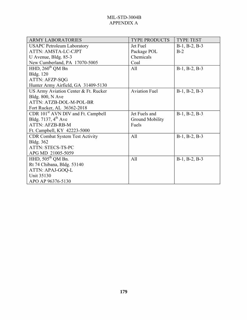
MIL-STD-3004B APPENDIX A
179
ARMY LABORATORIES TYPE PRODUCTS TYPE TEST USAPC Petroleum Laboratory ATTN: AMSTA-LC-CJPT U Avenue, Bldg. 85-3 New Cumberland, PA 17070-5005
Jet Fuel Package POL Chemicals Coal
B-1, B-2, B-3 B-2
HHD, 260th QM Bn Bldg. 120 ATTN: AFZP-SQG Hunter Army Airfield, GA 31409-5130
All B-1, B-2, B-3
US Army Aviation Center & Ft. Rucker Bldg. 800, N Ave ATTN: ATZB-DOL-M-POL-BR Fort Rucker, AL 36362-2018
Aviation Fuel B-1, B-2, B-3
CDR 101st AVN DIV and Ft. Campbell Bldg. 7137, 4th Ave ATTN: AFZB-RB-M Ft. Campbell, KY 42223-5000
Jet Fuels and Ground Mobility Fuels
B-1, B-2, B-3
CDR Combat System Test Activity Bldg. 362 ATTN: STECS-TS-PC APG MD 21005-5059
All B-1, B-2, B-3
HHD, 505th QM Bn. Rt 74 Chibana, Bldg. 53140 ATTN: APAJ-GOQ-L Unit 35130 APO AP 96376-5130
All B-1, B-2, B-3

MIL-STD-3004B APPENDIX A
180
DESC LABORATORIES TYPE PRODUCTS TYPE TEST Mail Address:
DFR Europe Petroleum Laboratory Unit 23135, Box 28 APO AE 09227
Sample Address: DFR Europe Petroleum Laboratory Bldg. 320, Rhine Ordnance Barracks Am Opelkriesel
D-67663 Kaiserslautern, Germany Phone: 49-631-536-6812 FAX: 49-631-536-7084
JP-8JP-8/JP-5JP-5 JPTS Jet A/A-1 Diesel (EN 590) Diesel (F76) Gasoline (EN 228) AVGAS (D910) Hydraulics
A (except D3701) A (exc. JFA-5, add.) A A (exc. Cetane # & Polycyc. Aromatics A (exc. D613) A (exc. Benzene Content, Oxygen Cont., Oxygenates) A B-2
Defense Energy Support Center Petroleum Laboratory - Pyongtaek APO AP 96218-02666 DSN 315-753-7291 Comm. (82)(031)-691-0963
Aviation Turbine JPTS Ground Mobility Packaged Products
A, except naphthalene’s A B-1, B-2, B-3 B-1 plus
Defense Energy Support Center Petroleum Laboratory - Anchorage Ft. Richardson, AK 99505-5700
Aviation Turbine DFA, DF1, DF2 Aviation Gasoline Motor Gasoline
B-1, B-2, B-3 B-1, B-2, B-3 B-1, B-2, B-3 B-1, B-2, B-3
NAVY LABORATORIES TYPE PRODUCTS TYPE TEST Naval Air Systems Command Fuels and Lubricants Division, AIR 4.4.5 22229 Elmer Road, Bldg 2360 Patuxent River, MD 20670 Ship samples to: Naval Air Systems Command HAZMART Bldg 2385 22680 Hammond Road Sample (AIR 4.4.5) Patuxent River, MD 20670
Aviation & Ship Fuels; Turbine Engine Oils (Special samples only as defined in NAVAIR 00-80T-109)
All
Norfolk Mid-Atlantic Fuels Testing Laboratory 9673 Virginia Avenue, Bldg. W-388 Norfolk, VA 23511-3323
JP-5 F-76 2190 (LTL)
B-2 B-1 B-2
FISC Jacksonville FL Code 700, Fuel Dept. 8808 Somers Road, Bldg. 56 Jacksonville, FL 32226-2600
JP-5 F-76
B-1 B-1

MIL-STD-3004B APPENDIX A
181
NAVY LABORATORIES TYPE PRODUCTS TYPE TEST NAVSTA Roosevelt Roads Fuel Division PCS 1008, Box 3402 FPO AA 34051
JP-5 F-76
B-1 B-1
NAS Keflavik Fuel Lab PSC 1003, Box 32 FPO AE 09728-0332
JP-5 B-1
U. S. Naval Station Rota Spain Attn: Fuels Officer PSC 819, Box 21 FPO AE 09645-4900
JP-5 F-76
B-2 B-1
FISC San Diego Attn: Fuel Lab 937 N. Harbor Drive San Diego, CA 93132-5095
JP-5 F-76 2190 (LTL)
B-2 B-2 B-2
FISC Puget Sound Manchester Fuel Department Attn: Q.A. Laboratory 7501 Beach Drive East Port Orchard, WA 98366
JP-5 F-76 2190 (LTL)
B-2 B-2 B-1
FISC Pearl Harbor Attn: Fuels Officer 1942 Gaffney St., Ste-100 Pearl Harbor, HI 96860-4549
JP-5 F-76 2190 (LTL)
B-2 B-2 B-2
Commander (N84) U.S. Naval Forces, Marianas DFSP Guam Fuel Division PSC 455, Box 190 FPO AP 96540-1500
JP-5 F-76 2190 (LTL)
C C C
Commanding Officer Code 704, FISC Yokosuka Hakozaki Fuel Department PSC 473, Box 11 FPO AP 96349-0011
JP-5 F-76 2190 (LTL)
B-2 B-2 B-2
FISC Yokosuka Fuel Department Sasebo Fuel Division Laboratory Branch Code 702.3 PSC 476, Box 6 FPO AP 96322-1504
JP-5 F-76 2190 (LTL)
B-2 B-2 B-2

MIL-STD-3004B APPENDIX A
182
NAVY LABORATORIES TYPE PRODUCTS TYPE TEST U. S. Navy Support Facility Diego Garcia Attn: Petroleum Testing Lab PSC 466, Box 4 FPO AP 96595-0004
JP-5 F-76 2190 (LTL)
B-2 B-2 B-2

MIL-STD-3004B APPENDIX B
183
SIGNIFICANCE OF TESTS
B.1 Scope. This appendix discusses the significance and purpose of some of the tests used in the quality surveillance of fuels and lubricants. This Appendix is not a mandatory part of this Standard. The information contained herein is intended for guidance only. B.2 General. Each of the various tests of fuels and lubricants indicated in the product specification has a certain significance in relation to the quality of the product tested. Certain ones can give a quick, easy and positive identification of the product and at the same time, aid in detecting the presence of contaminants. Although descriptions of the testing equipment and test methods are not to be included in this publication, it is considered worthwhile to include a brief statement on the significance and purpose of certain tests. These statements may assist by providing a better understanding and appreciation of the scope and importance of the Quality Surveillance Program. For a more detailed coverage of this subject, see the ASTM Manual 1, Manual on Significance of Tests of Petroleum Products.
B.3 Ash. The ash content of an oil is determined by burning off the organic matter and weighing the remaining inorganic materials. Straight mineral oils normally contain only a trace of ash. Oils containing metallic salts as additives have larger amounts of ash than straight mineral oils. Increase of ash content is indicative of contamination with inorganic matter such as sand, dust and rust. In the case of straight mineral oil this must be very low as any abrasive substance such as sand, clay, or rust may damage the internal metal surfaces of engines, fuel injectors, plug injection nozzles, or form deposits in the engine. Residual fuels should have low amounts of ash since some constituents of ash may cause corrosion or embitterment of boiler fire boxes and boiler tubes.
B.4 Bottom sediment and water. The bottom sediment and water test (BS&W) is conducted on fuel to determine the amount of water and other foreign materials that may be present. Excessive sediment plug the burner tips and may prevent proper atomization. Clogging of the strainers, accumulation of sediment in fuel tanks and formation of carbon deposits may be a result of a high percentage of BS&W. Water in the fuel may freeze and also clog the lines resulting in improper flow of the fuel.
B.5 Carbon residue. The results of the carbon residue test are an estimation of the carbonizing properties of a lubricating oil or fuel. The carbon residue on a lubricating oil is not directly related to carbon formation in an engine, but gives an indication of the type of carbon formation (loose and flaky, or hard and flinty) and is useful primarily as an identity and control test in conjunction with other specification tests. In diesel fuels, after distilling off 90%, the carbon residue on the last 10% must be low enough to avoid large carbon deposits that could cause coking in the fuel injectors and affect the fuel spray pattern. High carbon residual fuels should be carefully checked for sediment. The Ramsbottom test is the required test for both fuel and lubricants as it has better repeatability and correlates better to carbon formation.
MIL-STD-3004B APPENDIX B
184
B.6 Cetane index. An approximation of the cetane number (the ignition performance) of distillate diesel fuels, which does not contain a cetane improver additive, calculated from the API gravity and mid-boiling point or from density and recovery temperature measurements. B.7 Cetane number. The cetane number is a measure of the ignition performance of a diesel fuel obtained by comparing it to reference fuels in a standardized engine test and is based on a scale resembling that of octane numbers. This value is determined by a test method which measures the length of time (ignition lag) between injection and starting of combustion within the combustion chamber of an engine. The cetane number requirement varies with the type of diesel engine. Large, slow-speed units of stationary installations do not require high cetane numbers (below 40). Smaller, high-speed engines having 1,000 rpm or more require fuels of high Cetane number (above 40). The cetane number is related to operating and starting characteristics at low temperatures. The higher the cetane value, the better or easier the starting capability. Cetane number is not to be confused with cetane index. The cetane number is determined by ASTM D613; the cetane index is a calculated value and may not always equate with the cetane number.
B.8 Cloud and pour points. The cloud point is the temperature at which wax crystals or water in an oil or fuel appear, causing the oil or fuel to appear cloudy or hazy. In wick feed systems, the waxy crystals may clog the wick and either wax or water crystals may block filter passages in fuel systems. The cloud point is the limiting factor for controlling low-temperature operability of diesel and burner fuels. Vehicles and equipment experience low temperature fluidity problems (filter plugging, fuel line restrictions, and waxing) if operated with diesel fuels having cloud points above ambient temperature. The pour point is the lowest temperature at which flow is observed under controlled conditions. The pour point as determined by laboratory test procedures is only indicative of its behavior at low temperatures. The fact that an oil or a fuel has a specific pour point is not indication that it can be handled satisfactorily at that temperature. Because of the low temperatures encountered by aviation fuels in high altitudes and cold weather flying, the low temperature characteristics are determined by freezing point test.
B.9 Color. Various types of petroleum products such as aviation and automotive gasolines are dyed to permit a rapid visual determination of product type and grade. Visually detectable changes in color intensity or hue may be an indication of product contamination or deterioration. Aviation turbine fuels have no color limitations on procurement or use. This is not to be construed to mean visual color determination is without significance. Unexpected color changes require additional testing to ensure product quality. Progressive darkening of jet and distillate type fuels during storage is a good indication that oxidation is occurring with the formation of insoluble gums. Naphthas and solvents intended for use as fabric cleaners should be water white to prevent discoloration of the fabric.
B.10 Conductivity. This measures the electrical conductance of the fuel in pS/m. Conductivity additive reduces the amount of time necessary for static charges to dissipate. Conductivity readings can be affected by temperature readings. Figure B.1 shows the effect of temperature on a sample of JP-8 with Stadis 450.

MIL-STD-3004B APPENDIX B
185
-10 0 10 20 30 40 50 60 70 80 90 100 110 120
TEMPERATURE (°F)
FIGURE B.1 Conductivity
500 400 300 200 150 100 90 70 60 50 40 30
C
O
N
D
U
C
T
I
V
I
T
Y
pS/m
MIL-STD-3004B APPENDIX B
186
B.11 Copper Strip Corrosion. This test indicates whether a petroleum product is free of corrosive compounds. B.12 Distillation. The distillation test is a measure of the volatility of a product. The lower boiling fractions of a gasoline indicate the starting ability of an engine at the given temperature, and the engine’s ability to warm up quickly when using that gasoline. An excessive amount of highly volatile constituents in gasoline may cause vapor lock; conversely, an excessive amount of heavy-ends may not completely burn in the combustion chamber and consequently may cause damage through excessive crankcase dilution. Specifications designate minimum and maximum percentages to be evaporated at specified temperatures as well as initial and final boiling points of the product. A high end point and high percentage of residue may be indicative of contamination of gasoline with fuel or oil. Fuel with considerable lower initial boiling point or flash point may be indicative of contamination with gasoline. B.13 Existent gum. Existent gum is the amount of nonvolatile residue present in the gasoline or aviation turbine fuel at the time of test. The results indicate the quantity of gum deposition which may occur if the product is consumed immediately, but do not indicate the stability of the product toward gum formation on storage. As the name implies, the gum is a sticky, tacky, varnish-like material that is objectionable in fuel systems. When present in excess, it tends to clog fuel line filters, pump screens, aircraft engine fuel systems, carburetor jets, and cause manifold deposit and sticky intake valves.
B.14 Filtration time. The filtration time test determines the filterability of aviation turbine fuels. It is designed to identify those fuels which can cause rapid differential pressure build up in filtration equipment.
B.15 Flash point. The flash point of a product is an indication of its fire hazard during handling and storage. The flash point is primarily applicable to lower temperature boiling range products such as diesel fuel, JP-5, kerosene and solvents. It is also used to determine whether a product is contaminated. As an example, very small quantities of gasoline lower the flash point of diesel fuel considerably below the minimum safe operating level. On new lubricating oils, the flash point is used primarily for the purpose of identification and classification, and must be above the operating temperature of the equipment.
B.16 Foam stability. This paragraph addresses Government-owned lubricating oil. All lubricating oils foam to some extent when agitated. The foam that is formed in additive oils is often very stable and instead of breaking quickly tends to build in the oil system with subsequent oil loss through the breather outlets and other openings in the engine crankcase. Consequently, additive type motor oils are frequently treated with antifoam agents to eliminate potential foaming difficulties. The foam test requires agitating the oil sufficiently so a large quantity of foam is formed, then noting the time required for this foam to collapse. Some lubricants containing antifoam additive may fail initial foam tests. If they meet the foam requirements after agitation as described in Option A of ASTM D892, Foaming Characteristics of Lubricating Oils, they are satisfactory for use.

MIL-STD-3004B APPENDIX B
187
B.17 Fuel system icing inhibitor. This is a quantitative test to determine the concentration of diethylene glycol monomethyl ether in aviation turbine fuel. The FSII additive prevents ice formation in aircraft fuel systems. ASTM D5006 (using the B2 AIA Kit) is the preferred method. B.18 Gravity. The gravity of a petroleum oil is an index of the weight of a measured volume of the product. The API gravity of a petroleum oil is based on an arbitrary hydrometer scale which is to a specific formula:
Degrees API at 60oF = (141.5 / (Relative Density 60/60 oF)) - 131.5 (Source: API MPMS Chapter 1, Vocabulary, API Gravity)
The relative density of a petroleum oil or a mixture of petroleum products with other substances is the ratio of the weight of a given volume of the material at a temperature of 60 oF to the weight of an equal volume of distilled water at the same temperature. If the relative density is determined at a temperature other than 60 oF, the result is corrected to that temperature by the use of the appropriate correction tables. The higher the relative density, the lower the API gravity. The API scale is now used almost exclusively by the petroleum industry to designate the gravities of petroleum liquids. Correct gravity is important in the gauging of the liquid content of storage tanks, tankers and barges. A change of gravity may indicate a change of composition caused by mixing of grades of product. B.19 Knock value. The knock value is normally expressed as an octane number for automotive gasoline and as octane or performance number for aviation gasoline. These values are determined by actually comparing the knocking tendency of a fuel to laboratory standard test fuels of known knock value in a standard test engine. The significance of knock value is to indicate whether the fuel tend to burn uniformly and evenly in a cylinder without pre-ignition or detonation. Fuels of inadequate knock value reduce power output in all types of engines and, if used for more than brief periods, can cause overheating of the engine unit, burned pistons and cylinders, lubrication failure, and even piston and cylinder melting. B.19.1 Octane number-motor method. Octane number of automotive gasoline is determined by a method of test that is indicative of fuel antiknock performance in engines operating at high engine speeds and wide open throttle. B.19.2 Octane number-research method. Octane number of automotive gasoline is determined by a method of test that is indicative of fuel antiknock performance in engines operating at relatively low engine speeds, low engine temperatures and wide open throttle. B.19.3 Antiknock index ((R+M)/2). The antiknock index is the average of the motor and research octane numbers. This value indicates the knocking tendency of the fuel under average driving conditions. B.19.4 Octane/performance number-aviation method. Antiknock rating is determined by a method of test that indicates the knock characteristics at lean fuel-to-air ratio in engines operating under lean or cruise conditions.

MIL-STD-3004B APPENDIX B
188
B.19.5 Octane/performance number-supercharge method. Antiknock ratings are determined by a method of test that indicates the knock characteristics under supercharge rich mixture condition, corresponding to the mixture ratio used in an aircraft engine under takeoff and climbing conditions. The antiknock characteristics of a fuel above 100 octane are expressed in terms of a tetraethyl lead or performance number.
B.20 Lubricity. In lubricants it is proportional to film strength. In fuels it refers to a value that is measured either by the scuffing load wear test, the high frequency reciprocating rig test, or the BOCLE test. The tests were developed to determine the ability of the fuel to properly lubricate fuel-wetted components/surfaces. B.21 Potential gum or oxidation stability. Stability of a fuel is its ability to retain its original properties, except for evaporation losses, after prolonged storage. When added to fuel chemical inhibitors tend to retard gum formation, but they not reduce gum that has already been formed. The stability value is determined by a test that indicates the presence of gum materials and the relative tendency of gasoline and aviation turbine fuel to form gums after a specified period of accelerated aging. In addition, the formation of gum may reduce the knock values of gasoline. B.21.1 Oxidation stability. For automotive gasolines, the oxidation stability may be expressed as the induction period (sometimes called the breakdown time), which is measured as the time in minutes elapsed during the accelerated test until the fuel absorbs oxygen rapidly. B.21.2 Accelerated gum. For aviation gasoline and aviation turbine fuels the oxidation stability may be expressed as the potential or accelerated gum. It is the gum plus lead deposits (from leaded fuels) measured at the end of a specified accelerated aging (oxidation) period.
B.22 Sulfur. Grade 1K kerosene, intended for use in non-flue connected, burner appliances and in wicked illuminating lamps must not contain appreciable levels of sulfur in order to prevent the formulation of sulfur compounds in combustion gases. The presence of sulfur compounds may present a health and toxicological hazard.
B.23 Thermal oxidation stability for turbine fuels (JFTOT). The thermal oxidation stability for turbine fuels (JFTOT, ASTM D3241) measures the high temperature stability of gas turbine fuels, which subjects the test fuel to conditions that can be related to those occurring in gas turbine engine systems. Test results are indicative of fuel performance during gas turbine operations and can be used to assess the level of deposits that form when liquid contacts a heated surface that is at a specified temperature. B.24 Vapor pressure. The vapor pressure of a fuel is determined by the RVP test and indicates the tendency of the fuel to vaporize. Vapor Pressure increases with temperature for any given gasoline. Gasoline must have a certain vapor pressure to ensure adequate starting and accelerating qualities. B.24.1 Vapor lock. Too high a vapor pressure for the particular operating condition may cause what is commonly known as vapor lock, which prevents the fuel from reaching the engine.

MIL-STD-3004B APPENDIX B
189
B.24.2 Vaporization. The tendency of gasoline to vaporize in an automobile fuel system is indicated by the vapor-to-liquid ratio of that gasoline at conditions approximating those in critical parts of the fuel system. This test is currently used at procurement levels in conjunction with RVP to determine vaporizing properties of automobile gasoline. B.25 Viscosity. Viscosity is the measure of a liquid’s resistance to flow. The significance of viscosity depends on the intended use of the product. From the point of view of application and performance, proper viscosity is highly important since specified minimum and maximum rates of flow are required for all fuels and lubricating oils. In fuel, viscosity determination serves as an index of how it flow to the burners, the extent to which it be atomized and the temperature at which the fuel must be maintained in order for heavy residual fuel to be properly atomized.
B.26 Water and sediment. B.26.1 Aviation fuels. Significance of contamination of aviation fuels with water and sediment is covered in Section 5.9. B.26.2 Automotive fuels. Significance of contamination of automotive fuels with water and sediment is covered in Section 5.10. B.26.3 Diesel and burner fuels. Diesel fuels must be clean and should not contain more than a trace of foreign substances, otherwise fuel pump and injector difficulties may occur. Excessive sediment and rust plug the burner tip and the fuel not atomize properly. Water can cause rough operation and may corrode the fuel handling system, causing the formation of rust in the system and can also create significant microbiological deterioration problems. The type of equipment and type of burner fuels determine the amount of sediment that is permissible in the fuel. B.26.4 Lubricating oils. Care should be exercised to avoid contaminating lubricating oils with water, as it hasten the decomposition of many oils, wash out additives, emulsify, and lead to engine malfunctioning. In used lubricating oils, water sediment may indicate poor maintenance or malfunctioning of screens, or its formation may have been caused by condensation of combustion products. B.27 Water reaction. A measure of the presence of water-miscible compounds in aviation gasoline and turbine fuels (See Test Method 1070 in this Standard). An interfacial emulsion may indicate a carryover of treating compounds or contamination with surfactants (surface active agents). A change in fuel volume indicates a contamination with alcohol or other components which absorb appreciable amounts of water. An interface emulsion may also indicate contamination with microbiological growth. B.28 Water separation index modified (WSIM). The WSIM (also referred to as microseparometer or MSEP method) test measures the water separation characteristics of fuels. The test reflects the ease with which a fuel releasing dispersed or emulsified water surfactants has an adverse effect on the WSIM rating. Fuels having low WSIM rating poison filter/separators and prevent them from functioning properly.

MIL-STD-3004B APPENDIX B
190
B.29 Water tolerance. The ability of fuel and alcohol blends to resist separation into two phases when a known quantity of water is added.

MIL-STD-3004B APPENDIX C
191
RECEIPT AND QUALITY SURVEILLANCE OF COAL
C.1 SCOPE C.1.1 Scope. This appendix provides general instruction and procedures to be used by the Military Services and the Defense Logistics Agency in receipt and quality surveillance of coal. C.2 APPLICABLE DOCUMENTS C.2.1 General. The documents listed in this section are specified in C.3, C.4, and C.5 of this appendix. C.2.2 Non-Government publications. The following documents form a part of this appendix to the extent specified herein. Unless otherwise specified, the issues of this appendix are those cited in the solicitation or contract. ASTM INTERNATIONAL Annual Book of ASTM Standards, Section 5, Petroleum Products, Lubricants,
and Fossil Fuels, Volume 05.05 Gaseous Fuels, Coal and Coke ASTM D2013 Standard Practice for Preparing Coal Samples for Analysis
(DoD adopted) ASTM D2234 Standard Practice for Collection of a Gross Sample of Coal ASTM D4702 Standard Practice for Quality Management of Mechanical
Coal Sampling System ASTM D4749 Standard Test Method for Performing the Sieve Analysis of
Coal and Designating Coal Size (DoD adopted) (Copies of these documents are available at ASTM International, 100 Barr Harbor Drive, Box C700, West Conshohocken, PA 19428. (Electronics copies of ASTM standards may be obtained from http://www.astm.org.)

MIL-STD-3004B APPENDIX C
192
C.3 DEFINITIONS The definitions in Section 3 of this Standard apply to this appendix. C.4 GENERAL INFORMATION C4.1 Coal Rank. A classification designation that indicates the degree of coalification or metamorphism, that is expressed in successive stages according to percentages of fixed carbon, moisture, and ash. The degree of coalification is classified into four general categories, or “ranks”; lignite, sub bituminous, bituminous, and anthracite. C.4.1.1. Lignite. Also referred to as brown coal, is the lowest rank of coal. Lignite has the lowest carbon content, 25 – 35 percent and a heating value less than 8,300 BTUs per pound. Typically, lignite has high moisture, greater than 30 percent, and volatile content of ~27 percent. C.4.1.2 Sub bituminous. A coal whose properties range from those of lignite to those of bituminous coal. Typically, sub bituminous coal has a carbon content of 35 – 45 percent, and a heating value of 8,300 – 11,500 BTUs per pound. Sub bituminous coal has an inherent moisture content of 20 – 30 percent, and a volatile content of 35 – 47 percent. Sub bituminous coal generally has a much lower sulfur content than other types, making it an attractive, cleaner-burning fuel. C.4.1.3. Bituminous. A dense, firm black coal, representing about fifty (50) percent of the steam-electric power generation in the United States. It is also used as a raw material in the steel and coke industries. Bituminous coal has a carbon content of 45 – 85 percent, and a heating value of 10,500 – 15,500 BTUs per pound. Bituminous coal has a moisture content of 7 – 20 percent, and a volatile content of 14 – 36 percent. The only drawback to bituminous coal-fired power plants is the sulfur content. The sulfur content ranges from 0.5 – 3.0 percent by weight (5,000 – 30,000 ppm). C.4.1.4. Anthracite. The highest rank of coal, anthracite is a hard, brittle, lustrous coal. It represents only a very small segment of the U.S. coal market. Currently, it is only found in 11 northeastern counties of Pennsylvania. Anthracite has a carbon content of 85 – 98 percent and a heating value of 13,500 – 15,000 BTUs per pound. Anthracite coal has very low moisture content, less than 7 percent and a volatile content of 5 – 15 percent. C.4.2 Specifications. Coal specifications are based on the boiler requirements outlined by the coal-burning facility. Reduced efficiencies plus increased maintenance and handling costs are associated with the use of non-specification coal. Table C-1 outlines the significant coal combustion characteristics and sensitivities for six (6) different coal combustion technologies.
Table C-1 Significant Coal Characteristics
Combustion Performance

MIL-STD-3004B APPENDIX C
193
Properties Single Retort
Multiple Retort
Traveling Grate
Spreader Stoker
Pulverized Firing
Cyclone
Size Consist V V V V V V
Moisture M M I M V M
Caking Index I I V M N N
Ash Fusibility I I M M I V
Grind ability N N N N V N
Friability M M M M N N
Volatile Matter M M M I I M
Fixed Carbon N N N N M N
Ash Content I I I I M M
Calorific Value I I I N N N
Ash Viscosity M M M N I V
Ash Composition ♦ ♦ ♦ ♦ ♦ ♦
Sulfur ♦ ♦ ♦ ♦ ♦ ♦ ♦ ♦ ♦ ♦ ♦ ♦ V – Very important I – Important M – Minor importance N – Little/No importance ♦ Very important for fouling refractory, but little importance to combustion ♦♦ Important from a corrosive standpoint, but little importance to combustion C.4.2.1 Size requirement. The size requirement (size-consist) is also part of a coal specification. Double-screened coal is coal that has been screened for both top and bottom size. Size is defined by the percentage of the coal sample retained on top of the largest-sized screen and the percentage passing through the smallest-sized screen. An example of double-screened coal requirement is: 5%, weight, maximum for coal greater than 1 ¼ inch, and 15%, weight, maximum for coal less than ¼ inch. Single-screened coal is only screened for bottom size. Size is defined by the percentage of sample passing through the smallest-sized screen. An example of single-screened coal requirement is: 15%, weight, maximum for coal less than ¼ inch. C.4.2.2 Specification revision. A facility’s coal specifications may require revision based on equipment changes, operational problems or Environmental Protection Agency (EPA) compliances. The revision of the coal specification be accomplished by the submission of DD Form 416, Purchase Request for Coal, Coke or Briquettes. The request specify the new requirement or specification and must include justification for the revision or change. Changes needed during the contract performance require formal contract modification by the contracting officer. Contractor agreement and equitable price adjustment be obtained by the contracting officer to establish the new coal specification requirement. Until the contract is modified, coal ordered continue to comply with the original specification requirements. C.4.3. Significance of Testing. Many large consumers of coal, as well as most of the large coal mining companies, have laboratories that sample and analyze coal. This work is done by the consumer to verify the quality of the coal purchased and to measure the efficiency of their coal

MIL-STD-3004B APPENDIX C
194
burning equipment. The coal producer performs periodic analyses to monitor coal preparation methods and variations within a coal seam. Standards used for analytical testing of coal, along with coal specifications and definitions have been subjected to continuous study and refinement for more than 60 years by the American Society for Testing and Materials (ASTM). Adhering to these procedures is critical to the veracity of the sample results. Before any analysis is conducted, Care should be taken to insure that the sample represents the material being produced. A coal sample usually contains some ratio of coal particles and extraneous material such slate, pyrite, etc. The analysis is only as good as the sample it represents. C.4.3.1. Proximate Analysis. The proximate analysis is an evaluation of four items: moisture, volatile matter, fixed carbon, and ash. The sum of the percentages of each must equal 100 percent. This analysis is roughly designed to separate the combustible matter from non-combustible matter, and is used in some instances to determine rank. C.4.3.2. Calorific Value. The calorific value of coal, or heat content, is express in BTUs per pound. A BTU (British Thermal Unit) is the amount of heat required to raise one pound of water from 60°F to 61°F. The metric system expresses the heat content in calories. One BTU equals 252 calories. To compare the heating value of two or more coals, the calorific value must be expressed on a dry basis. C.4.3.3. Sulfur. Is a naturally occurring element in fossil fuels that originated during the coalification process. Sulfur combined with moisture creates a highly corrosive liquid that is detrimental to all carbon steel combustion equipment components. In recent years, the Environmental Protection Agency (EPA) along with state regulatory agencies has been scrutinizing the sulfur content of coal and other fossil fuels. When fuels containing sulfur are burned, sulfur dioxide (SO2) is formed in the combustion process and is discharge into the atmosphere along with other combustible byproducts such as hydrogen sulfide (H2S) and nitrogen oxides (NOx). If these emissions are combined with a sufficient quantity of water vapor then sulfuric acid is emitted into the atmosphere. This is commonly referred to as acid rain. For these reasons, the federal government has implemented stringent sulfur regulations in an attempt to drastically reduce the quantity of combustible byproducts emitted into the atmosphere. C.4.3.4. Ultimate Analysis. The composition of coal is better represented by the ultimate analysis. This analysis reports the percentage of carbon, hydrogen, sulfur, oxygen, nitrogen, and ash in a coal sample. It also provides the data needed to calculate combustion factors for steam generation plants. However the data provides little assistance in predicting the burning characteristics of coal in a fuel bed. C.4.3.5. Moisture. All coal has some form of moisture which acts as a diluents during the combustion process. As a rule, a one percent increase in moisture reduce the calorific value by 80-120 BTUs. Moisture may be considered as surface moisture that comes from external sources such as snow, rain, and mechanical cleaning processes, or inherent moisture (not external) which is proportional to the coals’ rank. The moisture reported in proximate analysis is both surface and inherent. High moisture can affect the handling characteristics of coal.

MIL-STD-3004B APPENDIX C
195
Freezing temperatures cause wet coal to amass, which directly effects offloading, pulverize capacity, and flow from storage bunkers. C.4.3.6. Ash. The chemical composition of the ash is important in determining the fouling characteristics in a boiler. The quantity of ash generated help determine the cost and type of ash handling equipment that is required for a given steam generation plant. There are four (4) fundamental measurements of coal ash with respect to clinkering tendency and slagging. They are the softening or fusion temperature of the ash, ash chemical composition, and the total percent ash in the coal. C.4.3.6.1. Initial Deformation Temperature (IDT) - the temperature at which the first rounding of the apex of the ash cone occurs. C.4.3.6.2. As Softening Temperature (AST) – the temperature at which the cone has fused down to a spherical lump in which the height is equal to the width at the base. C.4.3.6.3. Hemispherical Temperature (HT) – the temperature at which the cone has fused down to a hemispherical lump at which point the height is one half the width at the base. C.4.3.6.4. Fluid Temperature (FT) – the temperature at which the fused mass has is almost flat with a maximum height of 1/16 in. C.4.3.7. Volatile Matter. Volatile matter in coal is given off as volatile gases, such as hydrogen, carbon monoxide, methane, and sulfur dioxides. Volatile matter reflects the coals’ ability to ignite and burn. Coal having a low volatile content be more difficult to ignite and burn than coal having a high volatile content. Volatile content is a very important chemical characteristic during suspension burning. C.4.3.8. Free Swelling Index (FSI). Among the numerous test methods used to determine the expansion and swelling, or caking characteristics of coal, the free swelling index (FSI) is the most widely accepted. All bituminous coals coke in the sense that when the volatile matter is driven off by heat in the absence of air, the fixed carbon and ash remaining is coke. The caking characteristic of coal, however, is the tendency of coal to melt together into a solid mass. Caking characteristics have little or no effect on the performance of spreader stokers or pulverized coal fired boilers. C4.3.9. Petrographic Analysis. This type of analysis is typically conducted during a mine evaluation or pre-award survey. The Petrographic analysis of coal was originally used to study the lithography of coal as a sedimentary rock and to identify the various coal laminae. Two methods were used: the thin section method and the polished surface method. By studying the various lithotypes and microlithotypes present, a determination could be made with regards to the quantity of homogeneous constituents. These constituents are called macerals. Macerals can be distinguished into the following types: Macerals whose origin is definitely due to woody and cortical tissues are vitrinite, fusinite, and semi-fusinite. Macerals whose origin is definitely due to plant material other than woody tissues are resinite, sporinite, alginate, cutinite, and sclerotinite. Macerals whose origin has not yet been traced to a specific vegetable tissue is called

MIL-STD-3004B APPENDIX C
196
micrinite. Micrinite is completely structureless and was probably derived from humic mud and therefore from strongly decaying plant material. Since each of the various macerals has definite characteristics, a petrographer can determine the characteristics of a particular coal. By knowing the amount of the various macerals present, a petrographer can also predict a coals’ behavior under certain conditions. C.4.4 DESC contracts. Under DESC contracts coal is usually inspected at source, with acceptance at destination. The contractor samples and tests coal prior to delivery. Commercial analytical test reports are prepared and accompany the DD Form 250 before or along with the shipment. If the accompanying documentation, visual examination of the coal being delivered , or the sampling/testing of the coal being delivered shows failure to meet the contractual requirements, then it should be rejected as non-conforming (see C.5.10). The activity immediately provide notification to DESC with all pertinent information regarding off-specification coal. The contractor may request a waiver through the contracting officer for Government acceptance of the nonconforming coal. C.4.5 Quality control plan/procedures. The facility should establish a written quality control plan for each coal-burning facility (see C.5.1). C.4.6 Government representative. In the event work is contracted out a Government representative should be assigned to the contract. The representative serve as point of contact when coal is received, sampled, tested, or when problems arise. C.4.7 Personnel training. The receiving facility is responsible for acceptance and receipt sampling. Only personnel who have been trained and are experienced to receive, sample, and test coal should be assigned these functions. Guidelines or policy should require individual training programs and should document completed training. DESC teaches the “Coal Sampler’s Certification Course” to installation personnel on a cost-reimburseable basis. Contact DESC-QA (Phone 703-767-8736 or email [email protected]) to request the DESC “Coal Sampler’s Certification Course” training. Installations may provide this training through alternate means provided the same level of instruction is provided. Personnel assigned the responsibility of coal receipt should also be familiar with applicable coal contact requirements. Personnel not experienced in performing visual examination should receive on the job training from experienced personnel. C.4.8 Acceptance. When all contract requirements are satisfied, acceptance is accomplished by designated facility personnel on behalf of the Government. The DD Form 250 is completed by the responsible official by signing in block 21b, Acceptance. Block 22 is signed to acknowledge receipt quantity and may be signed by a Government or Government contract employee. The DD Form 250 is then forwarded to the proper office within 24 hours of acceptance to exact payment. C.5 DETAILED GUIDANCE C.5.1 Quality control plan.

MIL-STD-3004B APPENDIX C
197
C.5.1.1 Organization. The quality control plan should contain the name of a person responsible for coordination on changes and updates to the quality control plan. The quality control plan should also contain the name of personnel who are points of contact in receiving, storing, issuing and consumption. C.5.1.2. Schematic diagram. The quality control plan should contain a detailed schematic of the facility identifying the coal offloading locations, conveyor systems, sampling points, testing locations and storage locations. Information on the type of storage, handling equipment, additive treatment for dust reduction or freeze prevention, and movements of coal within the facility should be included. C.5.1.3 Government representative. The quality control plan should include name of the Government representative (see C.4.4), their telephone, cell phone, pager, and facsimile numbers. The quality control plan should include a sufficient notification time that allows the Government representative to be present when coal is received, sampled or tested. C.5.1.4 Documentation. Identify in the quality control plan who assure receipt of copies of solicitations, contract awards and modifications. Identify how product receipt documents such as DD Form 250s, test reports and weigh bills be received and distributed. Identify who prepare or receive supplemental documentation such as: blending records (if performed), corrective action requests, quality/quantity investigations, certificates of calibration (e.g. scales for determination of weight and any other testing equipment), and manufacturers’ certificates of conformance (additives for dust control, freeze proofing, etc.). State where (the office) and how long this documentation be kept. Note: Contract specified sampling and testing methods can be found in the Annual Book of ASTM Standards, Section 5, Petroleum Products, Lubricants and Fossil Fuels, Volume 05.05, Gaseous Fuels, Coal and Coke. C.5.1.5 Blending. If performed, the quality control plan should include detail procedures on how coal blending is accomplished. C.5.1.6 Sampling. The quality control plan should define and include minimum procedures for the following in the sampling plan: coal sampling for chemical analysis, size-consist, and additives (receipt and storage sampling). Include requirements for labeling and retaining samples. (Specify retention time for each sample.) A size consist sample must be retained for a full seven days. C.5.1.7 Testing. The quality control plan identify or contain the test procedures to be used for conducting each test. Table C-2 outlines by coal rank, the tests typically performed. If testing is contracted to a commercial laboratory, the testing requirements and methods be outlined in the QCP.
Table C-2 Coal Analysis
Analyses Properties Sub
bituminous Bituminous Anthracite

MIL-STD-3004B APPENDIX C
198
Proximate Analysis (H20, VM, FC, ash)
Chemical ● ● ●
Ultimate Analysis (C, H, O, N, S, ash)
Chemical ● ● ●
Calorific Value (Btus) Chemical ● ● ●
Fixed Carbon Chemical ● ● ●
Ash Content Chemical ● ● ●
Moisture Content Chemical ● ● ●
Volatile Matter Chemical ● ● ●
Sulfur Content Chemical ● ● ●
Grindability (Hardgrove Index) Physical ● ●
Ash Fusibility Physical ● ●
Caking Index Physical ●
Friability Physical ●
Free-swelling Index Physical ●
Size Consist Physical ● ● ●
C.5.1.8 Calibration of testing and measuring equipment. Include procedures in the quality control plan for the calibration of testing and measuring equipment, if used at the facility C.5.1.9 Credits and debits. The quality control plan should identify who monitor the credits and debits for coal contracts. C.5.1.10 Off-specification product/operational problems. The quality control plan should outline procedures for notification of nonconforming coal or operational problems related to using nonconforming coal. Include notification of DESC and SCPs when any problem arises, both remedial and preventative type of corrective action. Examples of areas to be included are: off-specification product during and after receipt and loss/gain investigations. C.5.1.11 Product rejection. Include in the QCP procedures on identifying conditions for rejection and notification of DESC. DESC Contracting Officer be notified of 0ff-specification coal and approve the rejection before it is returned to the contractor. C.5.2 Ordering and receiving procedures. All coal orders are issued and funded by the installation. All coal shipments should be inspected when received, before final acceptance. Clear and proper inspection procedures are essential, as they show compliance to contract requirements and are the basis for accurate analytical results. Proper inspection, sampling and testing procedures support coal being rejected and provide supporting evidence for a price adjustment claim. These procedures should also be timely because prolonged or delayed inspection could cause demurrage costs to accrue against railcars or contractor’s trucks. C.5.2.1 Documentation. Examine all documentation before offloading (e.g.; weigh bills, DD Form 250s, analytical test reports).

MIL-STD-3004B APPENDIX C
199
a. Rail shipment identification. Documentation for rail shipments be faxed by the contractor directly to the receiving facility, SCP and DESC Offices specified in the contract prior to shipment arrival. Rail cars may be separated in transit by the rail company in the course of normal business practices, therefore it is necessary to check each car number against the DD 250 for each shipment. Contractor documentation provided to destination should include sufficient information to identify the loaded cars by railcar number, quantity loaded, loading source, and consignee on the DD Form 250. b. Truck shipment identification. Commercial analytical test results for new stockpiles be faxed to the receiving facility before or concurrent with the first truck delivery from that stockpile. Material Inspection and Receiving Reports, DD 250s, identifying truck tickets and weights for each days delivery are to be provided to the receiving activity within 48 hours after delivery. c. Source of coal. Receipt documents should identify the required source listed in the contract. Coal from another mine may not be substituted except as authorized by contract modification. Before an alternate mine is added to the contract, a mine analysis sample should be performed to determine the mine’s capability to deliver spec coal. Report the use of unauthorized mines to the contracting officer immediately. C.5.2.2 Quantity determination. When quantity is determined by a facility’s weigh scale, and not by railroad weigh bill or truck scale weight, then the scales used be calibrated as required by state or local requirements, whichever is more stringent. C.5.2.3 Credits and debits. Credit and debits are determined based on the analytical test report data issued by the Army Petroleum lab. Coal may be regularily and continuously sampled by the using facility in accordance with ASTM D2234. The Army Petroleum lab analyze each sample with respect to the actual tonnage sampled. If the Army analysis report determines that any coal delivered does not meet the contractor’s guaranteed specification, the installation may apply its rights for credits and debits under contract clauses to include “Sampling and Evaluation” and “Consideration for Excess Sulfur and Ash”. If the final determination is a debit, then the contractor be debited before the closing of the contract. Credits not be issued. This data should be reported to the contracting officer prior to end of the contract (penalties for low ash or high sulfur be taken by the contracting officer directly for each delivery affected). C.5.2.4 Shipments after end of contract. The installation not order any coal after the contract expiration date. Deliveries of properly placed orders may be accepted up to the last day of the month following contract expiration. Note: The Contracting Officer may authorize a contractor’s request for acceptance of end-of-contract shipments, provided the installation is in agreement. C.5.2.5 Acceptance/rejection log. An acceptance/rejection log is recommended, recording all coal shipments accepted or rejected. This prevent the off loading of over shipments after contract completion. The following should be considered when developing a tracking system:

MIL-STD-3004B APPENDIX C
200
a. A method to assure that shipments and shipping notices are being made according to the delivery schedule. b. A schedule that indicates the type of coal and number of rail cars or trucks that are in transit. c. A record of delays in delivery and demurrage charges. Delays in offloading should be documented in detail to support payment of demurrage. Identify actions being taken (e.g. receipt sampling, testing), or other actions involved in the demurrage charges. C.5.3 Inspection procedures. All coal received is to be inspected and sampled for chemical analysis. Sampling techniques should comply with the standards cited in the contract for coal sampling methods. C.5.3.1 Visual examination. Visual inspections should be simple and thorough. They are mostly subjective, for example, examining coal by comparing to previous shipments. Each coal shipment should be visually inspected before unloading to assure that: a. The shipment is free from slate, bone, rocks, sulfur balls, dirt and other foreign material. b. The coal is properly prepared, is reasonably free from fines (coal smaller than the bottom screen size), oversize coal (coal larger than the top screen size), and is not weathered. If the coal does not appear to meet the minimum size requirements, as determined by visual examination and the facility wishes to reject the coal, a size-consist sample should be collected. The facility may elect to sample for size-consist on a regular or periodic basis for verification purposes. The size-consist analysis should be performed in accordance with C.5.8 below. c. There is no evidence of loss or theft in transit. During the visual examination assure railroad cars were loaded to full capacity. Loss in transit can occur when hopper doors are not completely closed during loading, doors are forced ajar during transit, a hole in a car is not patched properly, or hole patch worked loose. Ordinarily loss in transit can be determined by a depression in the contour of the coal above or near the holes or openings in the car. Theft usually occurs when cars stand for extended periods of time and can be detected by irregular appearances in the coal on the top of the car. A record should be kept with all information on discrepant shipments received, including car numbers and discrepancy observed. If losses appear to be something other than random theft, e.g.: losses occur regularly or from consistent locations, then fraud should be considered and reported to the proper authorities for investigation C.5.4 Sampling general. C.5.4.1 Personnel. Only personnel who are qualified by obtaining certification in accordance with the requirements of section C.4.7 collect and prepare the coal samples for official analysis. C.5.4.2 Sample preparation. Prepare samples in accordance with ASTM D2013.

MIL-STD-3004B APPENDIX C
201
C.5.4.3 Sample containers. Sample containers should be thoroughly clean, dry and inspected for foreign matter. Care should be taken to protect the gross sample when storing. Note: The use of glass containers for mailing is not permitted. C.5.4.4 Sample tags. Make complete and correct entries on samples tags regarding each sample to assure proper analysis and reporting of the sample submitted. The information listed in C.5.4.6 should appear on the sample identification tag. C.5.4.5 Sample retention time. When size consist is in dispute, the screened sample should be retained in a protected area for one week from the date the sample test was completed, or for a longer time, as determined by the QAR (the sample be available to the Contractor and the QAR for inspection). C.5.4.6 Sample identification for testing. Proper identification of coal shipments and timely submission of coal samples is essential. Inaccurate entries may result in preventing the receiving facility from recovering liquidated damages in claim actions for product substitution. The following information should be provided: a. Name and complete mailing address of the facility submitting the sample. b. Name of the contractor supplying the coal. c. Contract number. d. Contract line item number. e. Size and kind of coal. f. Tons represented by the sample. g. Railroad car, truck, or barge number/s. h. Name of mine and state where the mine is located. i. Sample number. j. Sample can number. k. Sampling point and ASTM condition used in obtaining sample. l. Date the coal was delivered. m. Provide mailing addresses of those who receive a copy of the analysis. n. Special test requested, i.e. hardgrove grindability index. o. Identification of coal sampler. p. Signature and date signed. C.5.4.7 Mailing coal samples for chemical analysis. Package the sample in accordance with ASTM D2013. Send samples to the following Army testing facilityor designated commercial laboratory for analysis: US ARMY PETROLEUM CENTER (USAPC) PETROLEUM TESTING FACILITY ATTN: AMSTA-LCEJPT, BLDG 85-3 U AVENUE NEW CUMBERLAND PA 17070-5005

MIL-STD-3004B APPENDIX C
202
When packaging and mailing “special” coal samples to be tested for dry ash or free swelling index include the following: a. Mark “Special Sample” for dry ash or free swelling index analysis. b. Include in Remarks: “Coal represented by this sample is subject to rejection”. c. Mark the mailing wrapper, “Special Sample”. d. Forward by air mail. e. Inform the DESC contracting officer, coordinating with the service control point, by telephone or facsimile that the sample was mailed, and provide the sample container number. This enable the Contracting Officer to expedite the testing of the coal sample. C.5.5 Sampling for chemical analysis. The collection of the gross sample for chemical analysis is the single most important function in the process of testing for coal quality and payment. Sampling for chemical analysis should occur at time of receipt. Automatic samplers in accordance with ASTM D4702 are best for obtaining coal samples due to consistency of timing and type of cuts. Coal may also be sampled manually in accordance with ASTM D2234 with the preferred sampling conditions being either condition A (Stopped-Belt Cut) or condition B (Full-Stream Cut). Condition C (Part-Stream Cut) and condition D (Stationary Coal Sampling) of ASTM D2234 are considered to be the least reliable methods of sampling coal. If condition C or D are called for in the contract, extreme care is needed to assure proper sampling. Table 2 of ASTM D2234 should be used when determining increment weight. It is recognized that in some cases it is not feasible to use either ASTM D4702 or ASTM D2234 conditions A, B, or C. Therefore, the following is provided as a guide in obtaining the samples for chemical analysis. C.5.5.1 Sampling equipment. All sampling devices should have an opening of at least two and one half times larger than the top size of the coal being sampled. The device should be capable of retaining the required increment weight and not spill material when the increment is withdrawn. Equipment such as a square shovel with built-up metal plates 4 inches (10 mm) high, a hand-operated auger, or a powered auger may be used in obtaining coal samples from stationary conveyances. The sample device should be capable of collecting the entire increment. Post-hole diggers may not provide a representative sample because small particles may escape. C.5.5.2 Procedures. For obtaining stationary samples, use diagrams and tables in ASTM D4915, for rail or trucks shipments (9-Point, Car top Sampling). The sampling guide in ASTM D4915 is to be used only when the preferred methods in ASTM D2234, condition “A” condition “B” or condition “C” are not feasible. Condition “D” is the least desirable method for the collection of a gross sample. The use of this method should only be used when it is required by the contract or when sampling conditions A, B, or C is not feasible. C.5.6 Sampling for dry ash and free swelling index. The gross sample for determination of ash and FSI should be obtained by using the methods outlined in ASTM D2234, Condition “D”, and ASTM D4915. Samples should be prepared in accordance with ASTM D2013.

MIL-STD-3004B APPENDIX C
203
C.5.7 Sampling for size consist. The facility is responsible for performing the size consist sampling and testing when required at destination for railcars and trucks. Stationary sampling of trucks may be performed by activity personnel, provided training and safety requirements are met. Sampling for size consist is performed when a visual inspection indicates coal exceeds the size requirement in the specification. If the facility does not have properly trained personnel or necessary equipment to perform the sampling or testing, the facility may contract for this function to an approved coal inspection company. When determining the size consist on coal received, use the contract specification requirement. C.5.7.1 Collection of the size consist sample (9-Point, car-top sampling method). Sample should be taken in accordance with figure C-1 below and ASTM D4915. A size consist sample should be no less than 453.59 kg (1000 pounds) taken in equal increments, from the nine points of each conveyance, representing one shipment of no more than five (5) conveyances, received in one day. The sample should be collected, weighed, and then screened without mixing or other preparation. The following minimum weights and increments are required for the number of cars and/or trucksto be represented by the sample.
Numbers of Conveyances
Minimum Weight fromEach
Point/Conveyance
Total Increment Weight
from Each Car 1 50.80 kg (112 lbs) 453.59 kg (1000 lbs) 2 25.40 kg (56 lbs) 226.80 kg (500 lbs) 3 17.24 kg (38 lbs) 151.50 kg (334 lbs) 4 12.70 kg (28 lbs) 113.40 kg (250 lbs) 5 10.42 kg (22 lbs) 90.72 kg (200 lbs)
FIGURE C.1. Weights and Increments
a. Lay out three diagonals across the top of each conveyance to be sampled (see figure C.2). Remove the top 450 mm (18 inches) of the coal from each of the diagonals to form trenches the width of the coal sampling device. Begin at the front corner of the conveyance extending diagonally across. Begin the second trench near the center and the third at the rear corner. Distribute the spoil over the top of the undisturbed coal where it not intrude into the sample. b. Collect equal increments from each of the nine sampling points. As can be seen from figure C.2., the sampling points 1, 3, 4, 6, 7, and 9 are located near the edge of the conveyance. c. The required minimum weight of each increment is found in the chart above. d. A shovel meeting ASTM D4915 requirements shall be used. Build up standard flat square shovel with two sides and back plates. Build up should be at least 4 inches (100 mm), constructed from metal. Exercise care in taking each increment to keep to a minimum the

MIL-STD-3004B APPENDIX C
204
quantity of coal falling from the sides into the bottom of the trench. Each shovel full taken without loss of coal is considered an increment. e. At each point (figure C.2.) proceed as follows: (1) Trench 1, first sampling point. Retain the first increment for the sample and spoil the second. Then alternately retain one increment and spoil one until the predetermined weight of coal is collected at point number 1. (2) Trench 1, second sampling point. Spoil the first increment then retain the second and third increment. Then alternately spoil two increments and retain one increment, until the predetermined weight is obtained. (3) Trench 1, third sampling point. Spoil the first two increments, retain the third and spoil the next three. Then alternately retain one and spoil three until the predetermined weight is collected. (4) Trench 2, fourth sampling point. Collect as trench 1, third sampling point (see above). (5) Trench 2, fifth sampling point. Collect as trench 1, first sampling point (see above). (6) Trench 2, sixth sampling point. Collect as trench 1, second sampling point (see above). (7) Trench 3, sampling points 7, 8, and 9. These sample points be handled the same as trench number 1, sampling points 1, 2, and 3, respectively.
FIGURE C.2. Car Top Sampling

MIL-STD-3004B APPENDIX C
205
C.5.8 Size-consist test procedures. The sieve analysis should be performed in accordance with ASTM D4749. C.5.8.1 Record of analysis. For each sieve analysis performed the following information should be recorded: a. Contractor providing the coal. b. Contract number and contract line item number. c. Conveyance identification and number/s. d. Mine name and seam the coal originated from. e. Method used in obtaining the sample (ASTM D2234). f. Date the sample was obtained. g. Date the sieve analysis was performed. h. Type, kind (round hole or square) and size of screen(s) used, and whether automatic or manual method was used. i. Percent of coal remaining on the screen (single-screen coal). j. Percent of coal remaining on the top screen, percentage of coal passing through the bottom screen and the total percent between the screens (double-screened coal). k. Percentage gained or lost. l. Name of the person performing the sieve analysis. C.5.8.2 Example of calculation. A sample of one thousand pounds was used to perform the sieve analysis. A double-screen analysis was required with a top size of 2″ and a bottom size of ¾″. One hundred pounds of coal remained on the top screen, and fifty pounds passed through the bottom screen after completion of the test. Eight hundred and fifty pounds remained between the two screens. Top size percent (weight of coal remaining on top screen) (100 lbs, top screen/1000 lbs, total sample) x 100 = 10% Bottom size percent (Weight of Coal Passing Through the Bottom Screen) (50 lbs pass thru, bottom screen / 1000 lbs, total sample) x 100 = 5% C.5.8.3 Testing accuracy. To ensure the accuracy of the size testing, a gain or loss percentage should also be calculated. A gain or loss percentage is the total weight remaining on the top screen, plus the total weight remaining on the bottom screen, plus the total weight passing
MIL-STD-3004B APPENDIX C
206
through the bottom screen, and divided by the total weight of the sample used to perform the test times 100. Gain (Loss) = (total weight of sample (1000 lbs)) minus (100 lbs top + 50 lbs pass bottom + 840
lbs remaining on bottom screen) / (total weight of sample (1000 lbs)) x 100 = 1% If the gain or loss is greater than two percent (2%), the testing tolerance has been exceeded and the results are invalid. The test should be repeated after validation of proper testing technique. C.5.9 Rejection of unidentified or non-conforming shipments. Shipments should be rejected for any of the following: a. A discrepancy exists in or between the shipping notices, weigh bills, and contract requirements or the DD Form 250 is not received. For example: coal is sent to wrong facility; coal is received from the wrong mine or contractor; receipt of an unauthorized over shipment; or coal test reports showing non-conforming coal. b. When visual examination shows non-conforming coal (inherent or foreign matter). (1) When rejection of coal is based on excessive inherent material (e.g.; slate, bone, dirt, rock or other contaminating material that through experience would fail the ash requirement), the Contractor may request the facility to obtain a sample and have the sample analyzed for ash content. The Contractor should make the request through the Contracting Officer within 48 hours after the notice of rejection. (2) When a shipment is rejected based on excessive foreign matter (e.g.; magnetite, wood, large sulfur balls, lumps of rock, slate), the facility should immediately advise the contracting officer through channels of the rejection. The contracting officer notify the contractor of the rejection. No sample for ash analysis is required for rejections based on foreign matter. (3) When the basis for rejection is excessive oxidized or weathered coal, the Contractor may request a sample be obtained and analyzed for FSI, if FSI is required or guaranteed by the contract (use the sampling procedures in C.5.6). (4) When visual examination indicates that a shipment be rejected for size consist, a sample should be obtained and a sieve analysis performed. Guidance for obtaining a sample for sieve analysis is found in C.5.7.1 (nine-point method). The nine-point method outlined, along with ASTM D4749 should be used as a standard for obtaining the 1,000 pound sample for testing for size consist. c. Coal shipment should be rejected when visual examination shows there is evidence of loss or theft in transit that exceeds the tolerances established by the railroad tariff. The facility should take action to have the shipment weighed as near to the point of acceptance as possible. If railroad scales are not available and the shipment cannot be weighed without delay, any excessive back haul or additional freight adjustments should be established by the railroad claim

MIL-STD-3004B APPENDIX C
207
agent or other designated individual. All parties involved in the dispute may, by visual examination, determine an agreed revised estimated weight to be accepted. As stated earlier, if losses appear to be something other than random theft, e.g., losses occur regularly or from consistent locations, then fraud should be considered and reported to the proper authorities for investigation. C.5.10 Product rejection procedures. When chemical samples taken during offloading are tested and reported as nonconforming, the Contracting Officer be notified, identifying the failing characteristic, quantity of coal, and location. C.5.10.1 Notification to Contracting Officer. The facility shall notify the Contracting Officer, DESC-APC (Phone: 703-767-8527; FAX: 703-767-8757), DESC-BPE (Phone: 703-767-8362; FAX: 703-767-8366), and DESC-QA (Phone: 703-767-8744; Fac: 703-767-8747). DESC-BPE monitors coal Product Quality Deficiency Reports (PQDRs). Include the following information:
a. Name of the Contractor b. Contract number c. Quantity of coal in tons awaiting disposition d. Date of shipment e. Status of the shipment f. Nature of the discrepancy or problem g. Point of origin
h. Railroad car or truck numbers i. Status of any ongoing or planned testing pertaining to the coal shipment, Chemical Analysis C.5.10.2 Notification of contractor. The contractor is formally notified of the rejection by the contracting officer. The contractor has the right to confirm coal quality or provide missing information. The contractor may request acceptance by the Government of nonconforming coal, referred to as a contract waiver request. The contracting officer provide the facility with disposition instructions on the rejected coal through required channels in a timely manner. C.5.10.3 Withdrawal of rejection. If testing shows the coal meets contract specification requirements, then the facility notify the contracting officer, coordinating with the service control point, of the results. The contracting officer then withdraw the rejection notice, notifying the contractor. The receiving facility is responsible for paying any charges associated with the delay of off loading the conveyances due to the unsubstantiated rejection. The facility

MIL-STD-3004B APPENDIX C
208
should not discuss with the contractor matters regarding nonconforming coal. Negotiations, as appropriate, are conducted through the contracting officer. C.5.11 Evaluation of the Coal. Upon receipt, the U.S. Army Petroleum Center or contract-designated laboratory test and issue an analytical test report of the coal sample. These reports are used to evaluate contractor performance. These reports can also be used by the facility to compare results received at origin to those received at destination. The price paid to the supplier may be adjusted either up or down based upon the test results of the sample taken at the destination (see C.5.2.3).

MIL-STD-3004B APPENDIX D
209
GOVERNMENT QUALITY SURVEILLANCE OF FUEL
D.1 SCOPE
D.1.1 Scope. This appendix provides general information on the Governments quality surveillance program for fuels, lubricants and related products. This appendix is not a mandatory part of this Standard. The information contained herein is intended for guidance only. D.2 APPLICABLE DOCUMENTS This section is not applicable to this appendix. D.3 DEFINITIONS The definitions in Section 3 of this Standard apply to this appendix. D.4 RESPONSIBILITIES D.4.1. Joint Petroleum Office (JPO). The JPO is responsible in overseas areas for ensuring an adequate quality surveillance program is maintained within the unified command. Direct communication between DESC and the JPO on all petroleum matters has been authorized. D.4.2 Military Services. The Service having physical possession of the petroleum products is responsible for establishing and maintaining a quality surveillance program. The Services also establish or furnish minimum usability limits for petroleum products. D.4.2.1 Non-conforming product. All Service-owned petroleum products exceeding allowable specification limits should be reported to the owning military Service Control Point for disposition instructions. For nonconforming Defense Working Capital Fund products, the Services retain the right of acceptance (see 5.13.5 for disposition procedures with non-conforming, Defense Working Capital Fund product). D.4.2.2 Service laboratory testing. See Appendix A for a breakdown of Service laboratories, their locations, and testing capabilities. For overseas locations, laboratory facilities are provided and maintained for the testing of fuels and lubricants in accordance with DLA 4155.29. The Military Service(s) should identify when laboratory support cannot be provided as cited above. D.4.2.3 Specification development. The Military Services, as engineering support activities, develop specifications, or accept specifications developed by other organizations. D.4.3 Headquarters DESC, its regions and offices. DESC maintains and oversees quality control programs to assure product quality is maintained from purchase to customer receipt. DESC maintains this Standard in coordination with the technical services.
D.4.3.1 Nonconforming Defense Working Capital Fund product. In addressing nonconforming, Defense Working Capital Fund product, the requirements of this Standard should be followed. When Defense Working Capital Fund products show deterioration beyond specification

MIL-STD-3004B APPENDIX D
210
requirements, DESC-QAQA or DSCR should be notified, as stated in 5.13.5 and 5.14.4. Customers should be notified prior to receiving product when only meeting intra-Governmental receipt limits. Service control points determine the acceptability of material not meeting intra-Governmental receipt limits. D.4.3.2 Commercial laboratory facilities for bulk petroleum products. DESC contracts for commercial laboratory testing of petroleum products worldwide in accordance with the needs of DESC and the Military Service(s). D.4.3.3 Defense Supply Center Richmond (DSCR). For packaged products, DSCR maintains and oversees quality control programs to assure product quality is maintained from purchase to customer receipt. D.4.3.4 Commercial laboratory facilities for packaged petroleum product. DSCR identifies and contracts for commercial laboratory testing of packaged products. The Military Service(s) identify to DSCR required testing coverage. D.4.4 Conflict with service publications. Anyone who has knowledge of a conflict between what is in this Standard and any Service technical publication is requested to bring it to the attention of DESC-QA/BP. Resolution of these conflicts be addressed individually. D.4.5 Quality surveillance representative (QSR) responsibilities. The QSR responsibilities include the following: a. Assure that the contractor establishes and maintains an acceptable program for the control of quality of petroleum products furnished to or handled for the Government. The contract may require a written quality control plan or procedures. b. Report to the region and the ordering officer at the activity placing the order, any information on delays in shipping the product caused by labor strikes, fires, or other conditions that result in non-availability of cargo or the inability of the contractor to perform. The reports should be made as soon as possible, but no later than the next working day, via telephone, fax, or e-mail. c. Perform the following, when requested: (1) Investigate petroleum product reported to be contaminated or causing unsatisfactory operation of equipment. The results of any findings given to a using activity are in an advisory capacity only. (2) Participate in pre-award surveys and post-award conferences. (3) Monitor/witness the analysis of special samples of products submitted to commercial laboratories under contract. (4) Maintain surveillance over the special blending and compounding of products.

MIL-STD-3004B APPENDIX D
211
(5) Assist the military supply and transportation offices on pertinent matters. (6) For issues effecting termination settlement at the facility, ascertain the quality and quantity of products on hand, volume of tank bottoms, and numbers of drums. d. Advise the contracting officer, through appropriate channels, of contractor noncompliance with contract provisions in those cases where adequate local correction is not possible or failure to report might jeopardize the rights of the Government under the contract. e. In contracts relating to receipt and storage of products procured for Government use, if the contractor does not provide technical personnel to perform laboratory testing, the QSR may be responsible for performing those tests necessary to assure the quality of products received, stored, and shipped at that location. Instructions contained in this Standard and DoD 4140.25-M should be used. f. Maintain vigilance over quality and quantity of Government-owned petroleum products, containers, and equipment in the possession of contractors. g. Advise the contracting officer of the date and time a commercial storage tank used to store Government-owned product is put into or out of service. Such reports apply to the removal of tanks from service for cleaning or repairs as well as initial use of termination of use under a contract. h. Verify inventory process for Government-owned petroleum product. The QSR certifies the accuracy of the inventory data and agrees or disagrees in writing with the contractor’s stated cause(s) of losses/gains. In the event that the QSR’s opinion as to loss data is at variance with the statements of the contractor, the QSR submits his reasons for nonoccurrence by letter to the office receiving the report. The QSR assures, to the extent practicable, that all factual data pertaining to losses are included in the stock report or in a separate letter. Certain contracts provide for periodic evaluations of contractor performance by the QSR. These reports are valuable tools in the correction of deficiencies and selection of contractors. Accordingly, such reports should factually report any and all significant areas and incidents of poor performance. Details relating to losses and accounting of Defense Working Capital Fund products are contained in the DoD 4140.25-M. There is no QSR certification on the DD Form 1788, Bulk Petroleum Terminal Report. The results of the periodic QSR inventory verification is documented with wording from the appropriate contract clause and filed with the individual transaction document. These documents are kept at the DFSP with a copy forwarded to the cognizant property administrator or accountable activity. The QSR witnesses the contractor inventories within the time intervals listed below. The QSR witnesses the contractor’s end-of-month inventories whenever the adequacy of the contractor’s inventory reporting system is questionable and continues until the contractor’s system is considered acceptable. The witnessing of the inventory and verification of the contractor’s system should be scheduled at different times within the intervals provided below with the contractor’s coordination. The following time intervals are the minimum, in determining the frequency of inventory verification:
MIL-STD-3004B APPENDIX D
212
(1) Active DFSP (three or more issues/receipts in six months): witness inventory and verify against receipts/issues monthly. (2) Semi-active DFSP (less than three issues/receipts in six month): witness inventory and verify against issues/receipts once each calendar quarter. (3) Commingled storage (Government-owned product stored with contractor-owned product): verify that sufficient inventory is on hand each calendar quarter. (4) Foreign Government and NATO held storage under memorandums of agreement (MOAs) or country-to-country agreements: inventory should be witnessed and verified by the QSR according to the terms of the agreement. i. Losses of Government-owned product in the custody of contractors, which are caused by accident or mishap, including line breaks, tank overflows, spillage, product contamination, and fire, are investigated by the QSR, and a detailed factual report is provided to the accountable activity and the contracting officer. j. Government property is subject to loss, damage, or destruction and may be found, upon receipt, to differ from the property indicated to have been shipped. In order to assist in the preparation of reports of survey, the QSR responsible for inspection of shipments received submits all pertinent information to the designated accountable activity and the contracting officer. k. Certain contracts require the QSR to certify the contractor invoice for specified services delineated in the contract, e.g.: guard service, laboratory testing services, overtime, etc. Since the QSR normally is not physically present at the facility during the entire period covered by the invoice, a certification as follows should be used. “Based on recorded checks made during surveillance of the contractor’s quality program and a review of the contractor’s time and attendance records, I certify the contractor’s invoice to be true and correct.” l. The QSR is responsible for developing their own checklists and tailoring them to the particular facility. m. SF 361, Transportation Discrepancy Report, is prepared by the designated accountable activity when Government-owned petroleum and related products, shipped on Government bills of lading, are received at a contractor’s facility in an improper condition, and such damage, loss, or destruction is attributable to causes incident to shipping. In order to facilitate the preparation of this report, the QSR responsible for inspection at contractor’s facilities receiving shipments submits all pertinent information to the designated accountable activity. The QSR checks shipments to determine the extent of the damage, shortage, and the cause, if possible. Information and documents submitted include: (1) Two true copies of Government bill of lading, including discrepancy notation on the reverse side.

MIL-STD-3004B APPENDIX D
213
(2) Certified true copies of the freight bill or delivery receipt showing any discrepancy notation and signature thereon. (3) A signed statement of the carrier’s local agent (carrier’s inspection report) admitting existence of the shortage or damage. It should be noted that this is not an admission of liability. (4) The receiving QSR checks signed statement containing the bill of lading number, the number of packages received, the condition of the packages, a record of seals on the car or vehicles at origin and destination, and whether applied by shipper or carrier, and a statements as to the cause of damage, if known or otherwise a reliable opinion based on circumstantial evidence be furnished. n. The QSR assists in the development of operating agreements, between the Government and the carrier that establish procedures for transportation, accountability, and quality control of Government fuel. The instructions applicable to petroleum movements via Government-owned multi-product pipeline systems are contained in this Standard and departmental instructions. o. The QSR assures that samples of Government-owned petroleum products in bulk storage at Government or contractor-operated terminals in CONUS are submitted in accordance with this Standard. p. When Government-owned stock in the custody of a contractor is indicated to be off-specification or projected to deteriorate below specification requirements in the near future, the QSR forwards copies of the test reports to DESC, ATTN: DESC-QA; and to the appropriate DESC Region. The reports should clearly indicate the product deficiency by appropriate comment on the reports and its relation to any recommended disposition action. q. Implemented in 1992, process control (formerly in-plant quality evaluation) is used in the quality surveillance program to assess the adequacy of contractors’ processes to consistently meet contractual requirements in storage and laboratory testing contracts. (Note: This does not apply to mandatory inspection requirements performed on vessel loadings/discharges, pipeline shipments/receipts.) For those contractor facilities whose processes are in control and where no customer complaints have been received, the cognizant QSR may reduce physical oversight at that facility. r. The QSR assists in the reporting and investigation of customer complaints or product quality deficiency reports (PQDRs) in a timely manner to DESC-QA. Basic PQDR information is input into the DESC-QA database (CDC); supplemental information is forwarded to DESC-QA. PQDRs are used to evaluate contractor performance under best value.

MIL-STD-3004B APPENDIX D
214
D.5 QUALITY CONTROL PLAN/PROCEDURES. D.5.1 Quality control plan/procedures. Each fuel handling activity is usually required to establish a written quality control plan. Service technical orders, field manuals, and instructions fulfill this requirement. For contractors, the contractor usually has the option to provide and maintain an inspection system that, as a minimum, incorporates the requirements such as those in Q91 (ISO 9001) Quality Systems - Model for Quality Assurance in Design/Development, Production Installation, and Servicing, or Q92 (ISO 9002) Quality Systems - Model for Quality Assurance in Production and Installation. However, the exact requirements for contractor quality control plans/procedures appear in the contract and those requirements rather than this appendix are what must be followed. If the owning service/contractor chooses to comply with Q91 or Q92 quality system format, then all the specific quality provisions listed below would normally be included in the Q91, Q92 written quality plan: D.5.2 Typical contents of a quality control plan/procedures. a. The existing organization of the service or storage facility is defined, identifying points of contact responsible for coordinating all quality control functions within the facility. In each key position a person should be appointed, such as laboratory, tank farm, docks, etc., to act as point of contact for operations. b. A quality control plan contains a detailed schematic of the facility. All areas covered by the inspection system are marked, such as blending, pipelines, tanks, docks, loading racks, laboratories, and all other areas concerning key processes. c. In the event responsibility for petroleum products has been contracted out, a quality control plan assigns a Government representative to the contractor and includes the representative’s name, their telephone, pager, and facsimile numbers, to allow contact. Notification is made for such operations as: testing, sampling, loading, discharges, or when an unscheduled situation arises that might cause a problem in product or service. Notification be in sufficient time, as identified in the quality control plan, to allow the representative to be present. d. Only competent and properly trained personnel are to be assigned responsibility of receiving/storing/releasing, sampling, and testing of Defense Working Capital Fund fuel. Established service guidelines or company policy should include an individual training program and the training completed should be documented. e. A quality control plan states how documents be controlled: A quality control plan outlines document distribution time for reporting, document retention time, and projected date for the next review and obsolete documents be removed from the area. Required documents include the quality control plan, specifications, test procedures, SOPs, and any other material directly affecting the inspection system. f. A quality control plan describes the procedures used for receiving both product and additives. This includes: item specification, quality procedures (receipt and storage), and a description of the location and overall receiving operation.
MIL-STD-3004B APPENDIX D
215
g. A quality control plan describes the procedures used for blending. This includes all products and additive injection at all locations. h. A quality control plan describes the sampling plan. The plan includes as a minimum procedures for the following: additives (receipt and storage); tank samples; line samples; conveyance samples; and samples to be taken prior, during, and after loading. The plan contains the method by which all samples be labeled and retained. The time of retention is also specified for each sample. Sampling is in accordance with the MPMS, Chapter 8, and retention times in accordance with this Standard. i. A quality control plan describes the tests to be conducted on each sample submitted. It contains the test procedures for each test. The requirements of Tables VIII and IX are incorporated into the plan. The plan specifies where the tests be conducted. When samples are to be shipped for testing, the plan states the quantity, type of container, identification, packaging, packing, and mode of shipment to be used. j. A quality control plan describes the method by which all laboratory and field testing and measuring equipment is calibrated in accordance with ISO 10012-1. For items not covered by that publication, the applicable manufacturer’s recommended calibration method(s) are used. k. A quality control plan includes detailed information on the type of storage and handling equipment and procedures to be used. All tanks, lines, valves, manifolds should be designed to handle the specified product and be in good repair. The plan includes a description of: the use of segregated/common product systems; controls to assure the capability for proper gauging, sampling, and draining of water; filtration; circulation; and other process/system used in maintaining product integrity during storage and handling. l. A quality control plan describes the manner by which products be moved from acceptance tanks to the conveyance. Examples of information needed are size of lines, type of product in lines, valves to be operated/blocked/blinded, how lines be packed, etc. The plan includes details on how product integrity be assured immediately before, during, and after loading and shipping operations. The plan gives detailed information on the procedures to be used to assure line fills meet specification requirements; conveyance inspection criteria prior, during, and after loading; completion and distribution of required documentation; and any other information deemed necessary. m. A quality control plan describes how all required records and reports be prepared and maintained. The plan states where, how, when, who, and for how long retained. The documents to be covered include, but not limited to, test reports (both additive and product), blending records, gauging records, movement records, dock logs, corrective action requests, quality/quantity investigations, ullage reports, DD Forms 250 and 250-1, bills of lading, certificates of calibration, manufacturers’ certificates of conformance, and any other documents affecting product. n. A quality control plan describes how the contractor determine the quantity of product and additives received, stored, injected, and shipped. All measurements are made in accordance

MIL-STD-3004B APPENDIX D
216
with the MPMS, Chapters: 2 (Tank Gauging), 5 (Metering), 7 (Temperature Determination), 10 (Sediment and Water), 11 (Physical Properties Data), 12 (Calculation of Petroleum Quantities), and 17 (Marine Measurement). Procedures should cover shore facilities and conveyances (vessels, trucks, pipelines, etc.) All quantities are determined by use of calibrated bobs and tapes, calibrated scales, or calibrated meters. o. A quality control plan outlines the complete plan of corrective action. This includes notification of DESC and DESC Regions when any unscheduled event arises that may affect product or service quality or quantity. It includes both remedial and preventative type of corrective action. Examples of items to be included (but not limited to) are: off-specification product (prior to, during, and after loading / discharge); conveyance rejection; leaks; loss/gain investigations, etc. D.6 NOTES This section is not applicable to this appendix.

MIL-STD-3004B
APPENDIX E
217
PRODUCT CHANGE RECORD
E.1 SCOPE E.1.1 Scope. This appendix provides general guidance on preparing a product change record. This appendix is not a mandatory part of this Standard. The information contained herein is intended for guidance only. E.2 APPLICABLE DOCUMENTS This section is not applicable to this appendix. E.3 DEFINITIONS The definitions in Section 3 of this Standard apply to this appendix. E.4 SUGGESTED FORMAT FOR A PRODUCT CHANGE RECORD E.4.1 Product Change Record. The following information should be included in a product change record. a. Location: Enter the name of terminal or location on line where data is being generated. b. Date: Indicate day, month, and year data was accumulated.
c. From: Indicate name, density (API gravity), and flash (if applicable) of head product. d. To: Indicate name, density (API gravity), and flash (if applicable) of material displacing head product. e. Pumping rate: Indicate barrels per hour and barrels per minute. f. Change arrived: Indicate dispatcher’s estimated time of product arrival and actual time of first gravity break.. g. Time: Indicate the hour and minute each line sample is taken.

MIL-STD-3004B
APPENDIX E
218
h. API gravity/density: Enter the API gravity/density of each line sample. i. Tank Number: Enter the number of the tank or tanks receiving the interface (if applicable). j. Flash: Indicate flash point in degrees Celsius (Fahrenheit) (if applicable). k. BBLS Mix: Indicate increment volume receiving from time of one sample to the next. l. Average API Gravity/density: Indicate average API gravity. m. Average relative density. Indicate the average API Gravity/density converted to relative density. n. Percent displacing product in mix: Enter in this column the results from the following formula:
((Average relative density of BBLS MIX) – (relative density of head product)) x 100 (relative density of displacing product) – (relative density of head product)
o. BBLS Displacing product in mix: Enter in this column the results of the following formula: (Percent displacing product in BBLS mix) x (BBLS mix) p. BBLS head product in mix: Enter in this column the result of the following formula: (BBLS Mix) - (BBLS Displacing product in mix) q. Gravity change: Enter in this column the result of the following formula: (Average relative density of BBLS MIX) – (Relative density of head product) E.4.2 Example of product change record. The product change record illustrates typical entries. An example of a minute increment calculation is as follows: a. Head product is gasoline with 66.1 API gravity and 0.7161 relative density. b. Displacing product is fuel oil with 41.4 API Gravity and 0.8184 relative density. c. Flow rate is 2025 barrels per hour or 33.74 BBLS per minute. d. Calculation: (1) Sample at 0809 (14 minutes): API: 45.9, SpGr: 0.7976

MIL-STD-3004B
APPENDIX E
219
(2) Barrels mix at 0809 (14 minutes) is 33.8. (3) Average gravity of volume increments at 0808 (13 minutes) at 0809 (14 minutes) is an API gravity of 47.2 API, or density of 0.7918. (4) (0.7918 (average relative density of BBLS Mix) - 0.7161 (relative density of head product)) x 100. (0.8184 (Relative density of displacing product) - 0.7161 (relative density of head pProduct)) = 73.99%, displacing product (fuel oil) is 73.99% of mix.
(5) (73.99% (displacing product of fuel oil mix)) x (33.8 (BBLS mix)) = 25.0 BBLS displacing product (fuel oil) in mix. (6) (33.8 (BBLSs mix) – (25.0 BBLS displacing product (fuel oil)) = 8.8 BBLS head product (gasoline) in mix. (7) Similar data should be calculated for each increment of change. The cumulative totals of each product are then added and inserted at bottom of applicable columns of the work sheet (see figure E.1.). E.5 NOTES This section is not applicable to this appendix.

MIL-STD-3004B APPENDIX E
220
Tim
e
API
Gra
vity
Tank
No.
Flas
h
Bbl
s Mix
Ave
rage
API
G
ravi
ty
Ave
rage
re
lativ
e de
nsity
% F
O in
M
ixtu
re
Bbl
s FO
in
Mix
ture
Bbl
s MO
GA
S in
Mix
QTY
Cha
nge
LOCATION: 7:55 66.1 PRODUCT: MOGAS 7:57 65.9 67.5 66.0 0.7165 0.39 0.27 67.2 0.0004 API GRAVITY: 66.1 7:58 65.8 33.8 65.9 0.7158 0.68 0.23 33.6 0.0007 RELATIVE DENSITY: 0.7161
7:59 65.7 33.8 65.8 0.7172 1.07 0.36 33.4 0.0011
FLASH: N/A 8:00 65.2 33.8 65.5 0.7183 2.15 0.73 33.1 0.0022 8:01 64.7 33.8 65.0 0.7201 3.91 1.3 32.5 0.0040 8:02 63.8 33.8 64.3 0.7227 6.45 2.2 31.4 0.0066 TO 8:04 61.7 67.5 62.8 0.7283 11.93 8.1 59.4 0.0122 PRODUCT: FUEL OIL 8:05 58.2 33.8 60.0 0.7389 22.29 7.5 26.3 0.0228 API GRAVITY: 41.4 8:06 54.1 33.8 56.2 0.7539 36.95 12.5 21.3 0.0378 RELATIVE DENSITY: 0.8184
8:07 50.3 33.8 52.2 0.7703 52.98 17.9 15.9 0.0542
FLASH: N/A 8:08 48.5 33.8 49.4 0.7822 64.61 21.8 12.0 0.0661 8:09 45.9 33.8 47.2 0.7918 74.0 25.0 8.8 0.0757 8:10 44.2 33.8 45.1 0.8012 83.19 28.2 5.6 0.0851 8:11 43.4 33.8 43.8 0.8072 89.05 30.1 3.7 0.0911 8:12 43.2 33.8 43.3 0.8095 91.30 30.9 2.9 0.0934 PUMPING RATE: 8:13 42.3 33.8 42.8 0.8118 93.55 31.6 2.2 0.0957 BARRELS PER HOUR: 2025 8:14 42.2 33.8 42.3 0.8142 95.89 32.4 1.4 0.0981 BARRELS/MINUTE: 33.75 8:15 42.0 33.8 42.1 0.8151 96.77 32.7 1.1 0.0990 8:16 41.4 33.6 41.7 0.8170 98.63 33.3 0.5 0.1009 8:18 41.4 67.5 CHANGE ARRIVED: 8:20 41.4 67.5 DISPATCHER EST: 0750 HRS
FIRST BREAK: 7:57 a.m.
FIGURE E.1. Sample calculation product change record

MIL-STD-3004B
APPENDIX F
221
COC DOCUMENT NUMBER
RECEIVING ACTIVITY LOCATION
NAME, GRADE AND TITLE OF PERSON FROM WHOM RECEIVED ADDRESS (Includ e Zip Cod e)
OWNER
OTHER
LOCATION FROM WHERE OBTAINED REASON OBTAINED TIME/DATE OBTAINED
SIGNATURE SIGNATURE
NAME, GRADE OR TITLE NAME, GRADE OR TITLE
SIGNATURE SIGNATURE
NAME, GRADE OR TITLE NAME, GRADE OR TITLE
SIGNATURE SIGNATURE
NAME, GRADE OR TITLE NAME, GRADE OR TITLE
SIGNATURE SIGNATURE
NAME, GRADE OR TITLE NAME, GRADE OR TITLE
SIGNATURE SIGNATURE
NAME, GRADE OR TITLE NAME, GRADE OR TITLE
Page 1
RELEASED BY RECEIVED BY
NO. QUANTITY
NO.
(Includ e p r od uct , seal num b ers, f inal d est inat ion , cond it ion and unusual m arks o r scrat ches)
OF CUSTODY
PURPOSE OF CHANGE
CHAIN OF CUSTODY
ITEM DATE
PETROLEUM SAMPLE CHAIN OF CUSTODY DOCUMENT
DESCRIPTION OF ARTICLESITEM

MIL-STD-3004B
APPENDIX F
222
CHAIN OF CUSTODY
SIGNATURE SIGNATURE
NAME, GRADE OR TITLE NAME, GRADE OR TITLE
SIGNATURE SIGNATURE
NAME, GRADE OR TITLE NAME, GRADE OR TITLE
SIGNATURE SIGNATURE
NAME, GRADE OR TITLE NAME, GRADE OR TITLE
SIGNATURE SIGNATURE
NAME, GRADE OR TITLE NAME, GRADE OR TITLE
SIGNATURE SIGNATURE
NAME, GRADE OR TITLE NAME, GRADE OR TITLE
SIGNATURE SIGNATURE
NAME, GRADE OR TITLE NAME, GRADE OR TITLE
SIGNATURE SIGNATURE
NAME, GRADE OR TITLE NAME, GRADE OR TITLE
SIGNATURE SIGNATURE
NAME, GRADE OR TITLE NAME, GRADE OR TITLE
RELEASED TO OWNER OR OTHER (Nam e/Un it )
DESTROY
OTHER (Sp ecif y)
ITEM(S) ON THIS DOCUMENT, PETAINING TO THE INVESTIGATION INVOLVING
(IS) (ARE) NO LONGER(Grad e)
(Nam e) (Organ izat ion )
REQUIRED AS EVIDENCE AND MAY BE DISPOSED OF AS INDICATED ABOVE. (If ar t icle(s) m ust b e ret ained , d o no t sign , b u t exp lain in sep ar
co r resp ond ence.)
(Typ ed /Pr in t ed Nam e, Grad e, Tit le) (Signat ure) (Dat e)
THE ARTICLE(S) LISTED AT ITEM NUMBER(S) (WAS) (WERE) DESTORYED BY THE EVIDENCECUSTODIAN, IN MY PRESENCE, ON THE DATE INDICATED ABOVE.
(Typ ed /Pr in t ed Nam e, Organ izat ion ) (Signat ure)
Petroleum Sample Chain of Custody Document - Page 2
FINIAL DISPOSITION ACTION
FINIAL DISPOSITION AUTHORIY
WITNESS TO DESTRUCTION OF EVIDENCE
OF CUSTODY
PURPOSE OF CHANGE
NO.
ITEM DATE
RELEASED BY RECEIVED BY

MIL-STD-3004B INDEX
223
Acceptable fuel (contamination)………………………………………..5.11.4…………………68 Acceptance (definition)............................................................................ 3.1.1.............................10 Acronyms and abbreviations used in this Standard ................................. 3.2................................67 Additional references ............................................................................... 6.5................................17 Additive concentration (corrosion inhibitor, pipelines)........................... 5.2.1.10.4.....................89 Additive injection/mixing (non-conforming product) ............................. 5.13.7.3........................41 Additives (definition)............................................................................... 3.1.2.............................77 Additives, receipt and injection ............................................................... 5.8................................10 After delivery / before departure (PC&S)................................................ 5.4.1.1..........................50 After discharge (tank truck/car) ............................................................... 5.3.2.4..........................47 AIR card................................................................................................... 5.6.1.............................49 Alcohol content (automotive gasoline).................................................... 5.10.4.6........................62 All level sample ....................................................................................... 4.2.1.4.1.......................20 Alternate test methods.............................................................................. 4.2.2.5.3.......................26 Appearance (definition) ........................................................................... 3.1.3.............................10 Applicability ............................................................................................ 1.2..................................1 Automatic sample .................................................................................... 4.2.1.4.11.....................21 Automotive spark ignition engine fuel (commercial gasoline)................ 5.10.4...........................61 Aviation fuel contamination and quality standards ................................. 5.11..............................65 Aviation turbine fuel ................................................................................ 5.10.2...........................57 Barge cargo tanks, minimum preparation requirements .......................... Table XXV ................152 Barge delivery.......................................................................................... 5.4.2.............................47 Barrel (definition) .................................................................................... 3.1.4.............................10 Batch cuts and segregation....................................................................... 5.2.1.7.2.......................40 Batch/lot samples ..................................................................................... 4.2.1.4.14.....................21 Before receipt (tank truck/car) ................................................................. 5.3.2.1..........................45 Bleeding (definition)................................................................................ 3.1.5.............................10 Blending (definition)................................................................................ 3.1.6.............................10 Blending, reclamation .............................................................................. 5.13.6.2........................77 Bottom sample ......................................................................................... 4.2.1.4.7.......................21 Bulk additives, receipt ............................................................................. 5.8.1.............................50 Bulk products (definition)........................................................................ 3.1.7.............................10 Bulk storage ............................................................................................. 5.9................................51 Bulk tanks, protective treatment .............................................................. 5.9.3.6..........................53 Bulk tank water restriction....................................................................... 5.9.2.............................51 Bunkering, after ....................................................................................... 5.5.3.............................48 Bunkering, before .................................................................................... 5.5.1.............................48 Bunkering, during .................................................................................... 5.5.2.............................48 Bunkers (definition) ................................................................................. 3.1.8.............................10 Calibrating test equipment ....................................................................... 4.2.2.7..........................26 Calibrating test equipment ....................................................................... 5.14.3.7........................81 Calibration (definition) ............................................................................ 3.1.9.............................10 Carbon residue on 10% bottoms .............................................................. 5.10.6.6........................64 Carbon residue on 10% bottoms .............................................................. 5.10.5.5........................63
MIL-STD-3004B INDEX
224
Cargo cleaning, required, MSC vessels ................................................... 5.1.1.3.2.......................28 Car top sampling (coal)............................................................................ Figure C.2..................203 Certificate of Conformance (definition) .................................................. 3.1.10...........................10 Certifying statements ............................................................................... 5.1.1.3..........................28 Cetane number ......................................................................................... 5.10.6.2........................64 Cetane number (ignition quality) (F-76).................................................. 5.10.5.1........................62 Chain of Custody ..................................................................................... 5.13.4...........................76 Changing product in a storage tank ......................................................... 5.9.3.2..........................52 Chromatography strip holder ................................................................... Figure 1 .....................168 Clean (clear) and bright (definition) ........................................................ 3.1.11...........................10 Cleaning of pipelines ............................................................................... 5.2.1.6.2.......................39 Cloud point............................................................................................... 5.10.6.5........................64 Cloudy or hazy fuel.................................................................................. 5.11.4.3........................68 Coalescing (definition)............................................................................. 3.1.12...........................11 Coal, receipt and quality surveillance of.................................................. Appendix C ...............189 Coal sampling, weights and increments................................................... Figure C.1..................201 Color (F-76) ............................................................................................. 5.10.5.2........................62 Color (gasoline, aviation)......................................................................... 5.10.1.2........................56 Color (gasoline, automotive, (/67)).......................................................... 5.10.3.2........................60 Color ........................................................................................................ 5.10.7.1........................64 Commingling (definition) ........................................................................ 3.1.13...........................11 Commingling with other petroleum products .......................................... 5.11.3.1........................66 Communication copies............................................................................. 5.13.3.1........................76 Conductivity (definition) ......................................................................... 3.1.14...........................11 Conductivity............................................................................................. 5.10.2.8........................59 Conductivity, chart................................................................................... Figure B.1..................183 Container inspection ................................................................................ 5.14.6.2........................82 Container sealant...................................................................................... 5.9.9.4..........................56 Container suitability................................................................................. 5.14.6.3........................82 Contaminant (definition).......................................................................... 3.1.15...........................11 Contaminated pipeline shipment.............................................................. 5.2.1.7.3.......................40 Contaminated product (definition)........................................................... 3.1.16...........................11 Contaminated product.............................................................................. 5.1.3.3..........................36 Contamination.......................................................................................... 5.14.6.9........................83 Contamination, ground fuel ..................................................................... 5.12.2...........................69 Contamination prevention........................................................................ 5.12.2.4........................71 Contamination problems.......................................................................... 4.2.1.10.1.....................25 Contamination, sources of ....................................................................... 5.9.9.............................55 Contamination tables ............................................................................... Table XXVII .............154 Contamination tests.................................................................................. 4.2.2.1..........................25 Contamination tests.................................................................................. 5.14.3.1........................80 Contamination with other fuels (commingling)....................................... 5.12.2.1........................69 Contamination with sediment .................................................................. 5.12.2.3........................70 Contamination with water........................................................................ 5.12.2.2........................70 Contamination with water, solids, and microbiological growth .............. 5.11.3.2........................66 Continuous sample (definition)................................................................ 3.1.17...........................11
MIL-STD-3004B INDEX
225
Conversion chart for tank cars and tank trucks........................................ Table XXIII ...............148 Conveyance composite sample ................................................................ 4.2.1.4.9.......................21 Corrosion (aviation turbine fuel) ............................................................. 5.10.2.3........................58 Corrosion (gasoline, automotive, F-67) ................................................... 5.10.3.5........................57 Corrosion (gasoline, automotive, D4814/A-A-52530) ............................ 5.10.4.4........................61 Corrosion control (pipelines) ................................................................... 5.2.1.10........................40 Corrosion inhibitors (pipelines) ............................................................... 5.2.1.10.2.....................41 Corrosives in tanks................................................................................... 5.9.2.1..........................52 Cracked stock (definition)........................................................................ 3.1.18...........................11 Cross Country System (pipeline) ............................................................. 5.2.1.7..........................40 Dedicated system (definition) .................................................................. 3.1.19...........................11 Dehydration (definition) .......................................................................... 3.1.20...........................11 Deteriorated product (definition) ............................................................. 3.1.21...........................11 Deterioration of a product........................................................................ 5.9.8.............................55 Deterioration of products ......................................................................... 5.14.7...........................85 Determination of sediment (solids - pipeline) ......................................... 5.2.1.10.1.....................41 Diesel fuel, biodiesel blend (ASTM B20 (A-A-59693)........................... 5.10.8...........................64 Discharge (tanker or barge receipts) ........................................................ 5.1.3.4..........................36 Dispensing from curbside pumps............................................................. 5.9.7.............................55 Dispensing fuel, references (pipeline) ..................................................... 5.2.1.8.3.......................40 Disposition procedures (non-conforming product).................................. 5.13.2...........................72 Disposition procedures............................................................................. 5.14.4...........................81 Dissolved water (definition) .................................................................... 3.1.22...........................11 Distillation (diesel, A-A-52557/ASTM D 975) ....................................... 5.10.6.4........................64 Distillation (F-76) .................................................................................... 5.10.5.4........................62 Documentation (packaged products) ....................................................... 5.14.6.1........................82 Dormant petroleum products, minimum frequency for testing ................................................................................................. Table VIII....................99 Dormant stocks (definition) ..................................................................... 3.1.23...........................11 Downgrading (definition) ........................................................................ 3.1.24...........................11 Downgrading (non-conforming product)................................................. 5.13.6.1........................77 Drain sample ............................................................................................ 4.2.1.4.6.......................21 Drum storage (packaged products) .......................................................... 5.14.6.4........................83 Dyed fuel (diesel)..................................................................................... 5.10.6.3........................64 Dyed turbine fuel (contamination)........................................................... 5.11.4.2........................68 Entrained water (definition)..................................................................... 3.1.25...........................11 Exception/quality data (tank truck shipment) .......................................... 5.3.1.2.1.......................43 Existent gum (aviation turbine fuel) ........................................................ 5.10.2.1........................57 Existent gum (gasoline, automotive (F-67)) ............................................ 5.10.3.3........................60 Existent gum (gasoline, automotive (ASTM D 4814/A-A-52530)) ........ 5.10.4.2........................61 Filtering (definition)................................................................................. 3.1.26...........................12 Filtering requirements(waterborne operations)........................................ 5.1.1.2..........................28 Filter-separator (definition)...................................................................... 3.1.27...........................12 Filtration................................................................................................... 5.9.5.............................55

MIL-STD-3004B INDEX
226
Filtration and water separation, minimum standards............................... Table XXVIII ............156 Filtration time (aviation turbine fuel) ...................................................... 5.10.2.6........................59 Flash point (F-76) .................................................................................... 5.10.5.3........................62 Flash point (kerosene).............................................................................. 5.10.7.2........................65 Flash point specification (aviation turbine fuel) ...................................... 5.10.2.5........................58 Free water................................................................................................. 5.11.4.1........................67 Free water (definition) ............................................................................. 3.1.28...........................12 Free water, AEL MK I or MK II fuel detector ........................................ Test Method 1060 .....173 Fuels Invoice/Acquisition Procedures .................................................... 5.7.3.............................50 Fuel, naval distillate (NATO F-76 MIL-DTL-16884)............................. 5.10.5...........................62 Fuel oil, diesel (A-A-52557, ASTM D 975)............................................ 5.10.6...........................63 Fuel quality and fuel contamination ........................................................ 5.11.3...........................66 Fuel system icing inhibitor (FSII) (aviation turbine fuel)........................ 5.10.2.4........................58 Fuel Standardization Policy……………………………………………..5.10.2.11 ......................59 Galvanized containers.............................................................................. 5.14.6.7........................83 Gaskets and hose connections (tank truck loading)................................. 5.3.1.3.5.......................44 Gasohol (definition) ................................................................................. 3.1.29...........................12 Gasoline and turbine fuel differences ...................................................... 5.11.1...........................65 Gasoline, automotive, unleaded (F-67)................................................... 5.10.3...........................60 Gasoline, aviation .................................................................................... 5.10.1...........................56 Gauging for water (definition) ................................................................. 3.1.31...........................12 Gauging or gaging (definition) ................................................................ 3.1.30...........................12 Government documents ........................................................................... 2.2..................................2 Government-owned property.(change in grade of fuel) .......................... 4.4................................27 Greases..................................................................................................... 5.14.7.3........................86 Ground mobility fuel contamination........................................................ 5.12..............................68 Ground Mobility Fuels............................................................................. 5.12.1...........................68 Gum (definition) ...................................................................................... 3.1.32...........................12 Handling personnel (bulk storage)........................................................... 5.9.9.2..........................56 Homogeneity (definition)......................................................................... 3.1.33...........................12 Hydraulic fluids ....................................................................................... 5.14.7.2........................86 Hydrocarbon contamination, in aviation gasoline ................................... Test Method 1040 .....166 Identification of piping system ................................................................ 5.9.3.7..........................53 Identification of transfers......................................................................... 5.9.10...........................56 Identification tests (definition)................................................................. 3.1.34...........................12 Inadvertent mixtures (bulk storage) ......................................................... 5.9.9.1..........................55 Inert-gas system (definition) .................................................................... 3.1.35...........................12 Injection, after (additives)........................................................................ 5.8.3.............................51 Injection, during (additives)..................................................................... 5.8.2.............................51 Innage (definition) ................................................................................... 3.1.36...........................12 Inspect (definition)................................................................................... 3.1.37...........................12 Inspection documents covering tanker and barge loading....................... 5.1.4.3..........................37 Inspection policy, MSC vessels ............................................................... 5.1.1.5..........................30 Inspection procedures cargoes ................................................................. 5.1.2.3..........................34

MIL-STD-3004B INDEX
227
Inspection requirements, waterborne cargoes.......................................... 5.1.1.4.3.......................29 Inspection, loading tankers and fleet oilers............................................. 5.1.1.7..........................33 Insulating oils........................................................................................... 5.14.7.4........................87 Intended use ............................................................................................. 6.1................................88 Interface (definition) ................................................................................ 3.1.38...........................12 International standard agreements ........................................................... 6.2................................55 Intra-Governmental receipt limit (definition) .......................................... 3.1.39...........................13 Intra-Governmental receipt limit, (Tables I-VII)..................................... 5.10..............................56 Intra-Governmental receipt limits for automotive gasoline..................... Table VII .....................98 Intra-Governmental receipt limits for aviation turbine fuels ................... Table I. ........................93 Intra-Governmental receipt limits for fuel, naval distillate (F-76) .......... Table III.......................94 Intra-Governmental receipt limits for fuel oil, diesel .............................. Table IV ......................95 Intra-Governmental receipt limits for fuel oil, diesel (F-54) ................... Table V........................96 Intra-Governmental receipt limits for fuel system icing inhibitor ........... Table II ........................94 Intra-Governmental receipt limits for gasoline, F-67 Unleaded.............. Table VI ......................97 Kerosene, F-58 (ASTM D 3699) ............................................................. 5.10.7...........................64 Knock rating (gasoline, F-18) .................................................................. 5.10.1.1........................56 Laboratories, military services................................................................. Appendix A ...............176 Laws, compliance with ............................................................................ 4.8................................27 Lead content (gasoline, automotive, F-67) .............................................. 5.10.3.4........................60 Lead content (gasoline, automotive, ASTM D 4814/A-A-52530) .......... 5.10.4.3........................61 Lead in fuels, determination of small amounts of.................................... Test Method 1030 .....164 Leaking valve contamination (bulk storage)............................................ 5.9.3.5..........................53 Light-ends (definition) ............................................................................. 3.1.40...........................13 Lines (vessel loading inspection)............................................................. 5.1.1.7.1.......................33 Loading inspection of tankers and fleet oilers ......................................... 5.1.1.7..........................33 Loading line (tank truck shipment).......................................................... 5.3.1.3.2.......................44 Loading plans, vessel ............................................................................... 5.1.1.5.4.......................31 Loading rates ........................................................................................... 5.1.1.7.2.......................33 Long-term storage (bulk) ......................................................................... 5.9.1.............................51 Loss or gain, unaccountable product ..................................................... 4.2.1.10.2.....................25 Lower sample........................................................................................... 4.2.1.4.4.......................21 Lubricating oils and gear oils................................................................... 5.14.7.1........................85 Lubricity (definition) ............................................................................... 3.1.41...........................13 Marine gasoil (definition) ........................................................................ 3.1.42...........................13 Marking of boxes and cartons ................................................................. 5.14.6.12......................88 Marking of contractor supplied product ................................................. 5.14.6.13......................88 Marking of used drums ........................................................................... 5.14.6.14......................85 Markings (pipelines),pumps, and valves ................................................. 5.2.1.3..........................38 Markings ................................................................................................. 4.2.1.8.1.......................24 Markings, field-filled container .............................................................. 5.14.6.11......................84 Markings, minimum container ................................................................ 5.14.6.10......................84 Material Inspection and Receiving Report (DD Form 250/250-1).......... 3.1.43...........................13 Measurement and sampling and calibration ............................................ 4.7................................27

MIL-STD-3004B INDEX
228
Micron (definition)................................................................................... 3.1.44...........................13 Middle sample.......................................................................................... 4.2.1.4.3.......................21 Mineral oil (definition) ............................................................................ 3.1.45...........................13 Mixed sample........................................................................................... 4.2.1.4.12.....................21 MMS Guidelines...................................................................................... 5.1.1.1………………..28 Multi-port inspection ............................................................................... 5.1.1.4.5.......................32 Multi-product pipelines............................................................................ 5.2.1.5..........................38 NATO codes (tank truck shipment)......................................................... 5.3.1.3.4.......................44 Nitrate ignition-type improvers in diesel fuel.......................................... Test Method 1050 .....171 Non-conforming product ......................................................................... 5.13..............................72 Non-conforming product (communication copies).................................. 5.13.3...........................74 Non-conforming product (disposition request)........................................ 5.13.2...........................72 Non-conforming product (custody requirements) ................................... 5.13.4...........................76 Non-Government publications................................................................. 2.3..................................3 Octane (gasoline, automotive, unleaded, F-67......................................... 5.10.3.1........................60 Octane (gasoline, automotive, ASTM D 4814/A-A-52530).................... 5.10.4.1........................61 Off-specification product (definition)...................................................... 3.1.46...........................13 Order of precedence................................................................................. 2.4..................................9 Other Government Documents, Drawings, and Publications .................. 2.2.2.............................59 Outage, or ullage (definition)................................................................... 3.1.47.............................3 Outlet (suction) sample ............................................................................ 4.2.1.4.10.....................13 Oxygenated fuel (definition).................................................................... 3.1.48...........................21 Packaged products ................................................................................... 5.14..............................77 Packaged product (definition).................................................................. 3.1.49...........................13 Packaging and storage of packaged petroleum products ......................... 5.14.6...........................82 Personnel competency. ............................................................................ 4.1................................20 Personnel conducting sampling ............................................................... 4.2.1.2..........................20 Personnel to conduct sampling (packaged products)............................... 5.14.2.2........................78 Pipeline batch (definition)........................................................................ 3.1.50...........................13 Pipeline receipts, before receipt............................................................... 5.2.2.1..........................42 Pipeline receipts, completion................................................................... 5.2.2.3..........................42 Pipeline receipts, during receipt............................................................... 5.2.2.2..........................42 Pipeline tender (definition) ...................................................................... 3.1.51...........................14 Pipeline transfer velocity ......................................................................... 5.2.1.5.3.......................39 Placarding (tank truck)............................................................................. 5.3.1.3.10.....................45 Post loading – tankers and barges............................................................ 5.1.4.............................37 Precautions (packaged products) ............................................................. 5.14.2.1........................77 Pre-loading and loading inspection (barges)............................................ 5.1.2.1..........................34 Pre-loading inspection of tankers and fleet oilers.................................... 5.1.1.5..........................30 Pre-loading procedures (vessels) ............................................................. 5.1.1.6..........................32 Pressure drop............................................................................................ 5.2.1.10.3.....................41 Procedures at the loading rack ................................................................. 5.3.1.3.3.......................44 Product change record.............................................................................. Appendix E................215 Product change, sample calculation ........................................................ Figure E.1, E.4.2 .......218
MIL-STD-3004B INDEX
229
Product compatibility (pipelines)............................................................. 5.2.1.6.1.......................39 Product conversion................................................................................... 5.1.2.2..........................34 Product equilibrium……………………………………………………...3.1.52 ..........................14 Product free fall (tank truck shipment) .................................................... 5.3.1.3.7.......................44 Production identification (multi-product pipelines)................................. 5.2.1.5.1.......................39 Product receipt (packaged products)........................................................ 5.14.1...........................77 Pumping time (pipelines)......................................................................... 5.2.1.5.2.......................39 Purification............................................................................................... 5.13.6.4........................77 Quality (definition) .................................................................................. 3.1.53...........................14 Quality and contamination, aviation fuel................................................. 5.11.3...........................66 Quality and quantity determination (vessel movements)......................... 5.1.1.5.6.......................32 Quality assurance (definition).................................................................. 3.1.54...........................14 Quality assurance representative (definition) .......................................... 3.1.55...........................14 Quality fuel deliveries,............................................................................. 5.11.2...........................65 Quality, product cargo check (bulk storage tank).................................... 5.9.3.3..........................52 Quality status listing (definition) ............................................................. 3.1.56...........................14 Quality surveillance (definition) .............................................................. 3.1.57...........................14 Quality surveillance of fuel, government................................................. Appendix D ...............207 Quality surveillance procedures (pipelines)............................................. 5.2.1.11........................41 Quality surveillance program (definition) ............................................... 3.1.58...........................14 Quality surveillance representative (definition)....................................... 3.1.59...........................14 Quantity, determination of (tankers and barges)...................................... 5.1.4.2..........................37 Quantity variation (tankers) ..................................................................... 5.1.1.4.5.......................29 Receipt limits ........................................................................................... 5.14.3.3........................80 Receipts of aviation secured fuel ............................................................. 5.7................................49 Receipts by pipeline................................................................................. 5.2.2.............................42 Receipts from the bunkering program ..................................................... 5.5................................47 Receipts from the into-plane program ..................................................... 5.6................................49 Receipts, tanker or barge, completion...................................................... 5.1.3.5..........................36 Receipts, tanker or barge, shore side ....................................................... 5.1.3.1..........................35 Receipts, tank truck/car............................................................................ 5.3.2.............................45 Receipts under the post, camps & station (PC&S) .................................. 5.4................................46 Reclamation (definition) .......................................................................... 3.1.60...........................15 Rehabilitation (definitions ....................................................................... 3.1.61...........................15 Refueling units (into-plane) ..................................................................... 5.6.2.............................49 Regulations and laws, compliance with................................................... 4.8................................27 Relative density (definition) .................................................................... 3.1.62...........................15 Repeatability (definition) ......................................................................... 3.1.63...........................15 Reproducibility (definition) ..................................................................... 3.1.64...........................15 Required cargo cleaning…………………………………………………5.1.1.4.2 ......................28 Requiring installation (definition)............................................................ 3.1.65...........................15 Responsibility (packaged products)......................................................... 5.14.2.3........................77 Responsibility (tanker inspection) ........................................................... 5.1.1.5.1.......................30 Responsibility for off-specification cargo (tanker inspection) ................ 5.1.1.6..........................30

MIL-STD-3004B INDEX
230
Retained samples ..................................................................................... 4.2.1.8.3.......................24 Rubber surface to fuel (bulk storage)....................................................... 5.9.9.3..........................56 Rust inhibitors’ effectiveness (pipeline) .................................................. Test Method1000 ......158 Rust test, internal, vessel tank.................................................................. 5.1.1.4.3.......................29 Safety (tank truck shipment).................................................................... 5.3.1.3.1.......................44 Safety precautions.................................................................................... 4.6................................27 Sample (definition) .................................................................................. 3.1.66...........................15 Sample serial numbers ............................................................................. 4.2.1.8.2.......................24 Sample, single tank composite................................................................. 4.2.1.4.8.......................21 Sample size, jet fuel ................................................................................. 4.2.1.7.3.......................24 Sample size, normal ................................................................................. 4.2.1.7.1.......................24 Samples, size of (packaged products)...................................................... 5.14.2.6........................79 Sample size, special ................................................................................. 4.2.1.7.2.......................24 Sample tag……………………………………………………………….3.1.67...........................15 Samples, identification of ........................................................................ 4.2.1.8..........................24 Samples, identification of (packaged products)....................................... 5.14.2.7........................79 Samples, size of ....................................................................................... 4.2.1.7..........................24 Samples, taking of.................................................................................... 4.2.1.5..........................21 Samples, types of ..................................................................................... 4.2.1.4..........................20 Samples, types of (packaged products).................................................... 5.14.2.4........................78 Sampling (general requirements). ............................................................ 4.2.1.............................20 Sampling (packaged products)................................................................. 5.14.2...........................77 Sampling and testing, for petroleum products(minimum)....................... Table IX ....................100 Sampling apparatus, containers, and procedures ..................................... 4.2.1.5.1.......................21 Sampling apparatus, containers and procedures (packaged products)..... 5.14.2.5........................78 Sampling, precautions.............................................................................. 4.2.1.6..........................23 Sampling, precautions (general). ............................................................. 4.2.1.1..........................20 Sampling, responsibility .......................................................................... 4.2.1.3..........................20 Scope........................................................................................................ 1.1..................................1 Sealing (tank truck and tank cars)............................................................ 5.3.1.3.9.......................45 Sediment in fuel (aviation fuel) ............................................................... 5.11.4.4........................67 Segregation (pipeline).............................................................................. 5.2.1.9..........................40 Segregation during transfer (pipelines).................................................... 5.2.1.5.4.......................39 Segregation of product (bulk storage tanks) ............................................ 5.9.3.4..........................53 Segregation of product movements via multi-product pipelines ............. Table XXVI...............153 Service and DLA responsibilities, (packaged products).......................... 5.14.5...........................81 Service/contractor responsibilities ........................................................... 4.2................................20 Settling time (definition).......................................................................... 3.1.68...........................15 Settling time in tank (bulk storage).......................................................... 5.9.3.8..........................53 Shelf life (definition)................................................................................ 3.1.69...........................15 Shipments by barges and refueling craft.................................................. 5.1.2.............................34 Shipments by pipelines. ........................................................................... 5.2.1.............................38 Shipments by tank cars and tank trucks................................................... 5.3.1.............................42 Shipments by tanker and fleet oilers........................................................ 5.1.1.............................28 Significance of tests ................................................................................. Appendix B ...............181

MIL-STD-3004B INDEX
231
Specification (definition) ......................................................................... 3.1.70...........................16 Specification limits (definition) ............................................................... 3.1.71...........................16 Specifications (general requirements)...................................................... 4.3................................26 Specifications, Standards, and Handbooks .............................................. 2.2.1...............................2 Specific gravity (definition)..................................................................... 3.1.72...........................16 Static electricity, control of (aviation turbine fuels) ................................ 5.9.4.............................54 Stock rotation (packaged products) ......................................................... 5.14.6.6........................83 Storage of similar products (bulk storage)............................................... 5.9.3.1..........................52 Storage, separate (packaged products)..................................................... 5.14.6.5........................83 Storage, small container (packaged products) ......................................... 5.14.6.8........................83 Storage tank (definition) .......................................................................... 3.1.73...........................16 Storage tanks and piping (bulk storage)................................................... 5.9.3.............................16 Subject term (key word listing)................................................................ 6.4................................88 Suitability to load (tankers)...................................................................... 5.1.1.4.4.......................29 Sulfides in water, test for ........................................................................ Test Method 1020 .....162 Sulfur (kerosene)...................................................................................... 5.10.7.3........................64 Super-clean fluid (definition)................................................................... 3.1.74...........................16 Surfactant (definition).............................................................................. 3.1.75...........................16 Synthetic oil (definition) .......................................................................... 3.1.76...........................16 System isolation (pipeline) ...................................................................... 5.2.1.7.4.......................40 Tailoring guidance ................................................................................... 6.3................................88 Tanker cargo tanks preparation of ........................................................... Table XXIV...............150 Tanker inspection policy for MSC vessels .............................................. 5.1.1.4..........................28 Tanker, receipts........................................................................................ 5.1.3.............................35 Tank protective treatment (bulk storage)................................................. 5.9.3.6..........................53 Tank truck/car arrival............................................................................... 5.3.2.2..........................45 Tank truck conversion policy................................................................... 5.3.1.2..........................42 Tank truck loading ................................................................................... 5.3.1.3..........................44 Tank truck rejection ................................................................................. 5.3.2.3..........................46 Tank truck service / conversion ............................................................... 5.3.1.1..........................42 Tariffs and agreements (pipeline) ............................................................ 5.2.1.1..........................38 Terminal, depot and base system (pipelines)........................................... 5.2.1.6..........................39 Test, equivalent ........................................................................................ 4.2.2.5.1.......................26 Testing (definition) .................................................................................. 3.1.77...........................16 Testing (general requirements) ................................................................ 4.2.2.............................25 Testing capabilities (general)................................................................... 4.2.2.6..........................26 Testing frequency (general) ..................................................................... 4.2.2.3..........................25 Testing frequency (dormant petroleum products..................................... 5.14.3.4........................80 Testing, laboratory (pipeline shipments) ................................................. 5.2.1.2..........................38 Testing, minimum (general)..................................................................... 4.2.2.4..........................26 Testing minimum, (packaged products) .................................................. 5.14.3.5........................80 Testing (packaged products) .................................................................... 5.14.3...........................80 Testing, predictive.................................................................................... 4.2.2.5.2.......................26 Test methods (general)............................................................................. 4.2.2.2..........................25

MIL-STD-3004B INDEX
232
Test methods (packaged products)........................................................... 5.14.3.2........................80 Test required (packaged products)........................................................... 5.14.3.6........................80 Test results, recording (tank truck shipment) .......................................... 5.3.1.3.8.......................44 Tests, identification (pipelines)................................................................ 5.2.1.4..........................38 Tests required, Support for Secured Fuels............................................... Table XIII..................110 Tests required, automotive gasoline ........................................................ Table XIV..................111 Tests required, aviation gasoline.............................................................. Table X......................107 Tests required, aviation turbine fuels....................................................... Table XII ...................109 Tests required, burner fuels...................................................................... Table XVI..................112 Tests required, diesel fuels and kerosene................................................. Table XV...................112 Tests required, lubrication oils................................................................. Table XI ....................108 Tests required, types of (general)............................................................. 4.2.2.5..........................26 Thief (definition)...................................................................................... 3.1.78...........................17 Thirty minute wait (loading vessels)........................................................ 5.1.1.7.3.......................33 Tolerance (definition) .............................................................................. 3.2.79...........................17 Top sample............................................................................................... 4.2.1.4.5.......................21 Transfer lines and pumps for fuels, common. (pipeline) ......................... 5.2.1.8..........................40 Transfer lines and pumps, preferred method (pipeline)........................... 5.2.1.8.1.......................40 Transfer lines and pumps, use of water displacement (pipeline)............. 5.2.1.8.2.......................40 Truck arrival / before delivery (PC&S) ................................................... 5.4.1.............................46 Tube or thief sample ................................................................................ 4.2.1.4.13.....................21 Turbulent flow (pipeline)......................................................................... 5.2.1.7.1.......................39 Type B-2 tests for greases, semi-fluid lubricants..................................... Table XVIII ...............114 Type B-2 tests for hydraulic, brake, and shock absorber fluids............... Table XIX..................129 Type B-2 tests for lubricants (including solid film)................................. Table XX...................133 Type B-2 tests for lubricating oils ........................................................... Table XVII ................113 Type B-2 tests for miscellaneous products .............................................. Table XXII ................140 Type B-2 tests for waxes.......................................................................... Table XXI..................137 Ullage (definition).................................................................................... 3.1.80...........................17 Ullaging and sampling JPTS cargo ranks or vessels ............................... 4.2.1.10........................25 Upper sample ........................................................................................... 4.2.1.4.2.......................21 Valve and pipeli21ne control ................................................................... 5.2.1.6.3.......................39 Vapor pressure (definition) ...................................................................... 3.1.81...........................17 Vehicle tank cleanliness (tank car and truck shipment)........................... 5.3.1.3.6.......................44 Vessel inspection, pre-loading ................................................................. 5.1.1.5.1.......................30 Vessel pre-discharge inspection (tanker or barge receipts). .................... 5.1.3.2..........................35 Vessel pre-loading plans .......................................................................... 5.1.1.5.4.......................31 Vessel rejection/delay (tankers)............................................................... 5.1.1.3..........................32 Vessel samples (post-loading tankers and barges)................................... 5.1.4.1..........................37 Vessel tank inspection.............................................................................. 5.1.1.4.2.......................30 Visual quality surveillance test ................................................................ Test Method 1010 .....160 Volatile alky lead antiknock (definition) ................................................. 3.1.82...........................17 VP (aviation turbine fuel) ........................................................................ 5.10.2.2........................58 VP (gasoline, automotive, 67) ................................................................. 5.10.3.6........................60

MIL-STD-3004B INDEX
233
VP (gasoline, automotive, ASTMD4814/A-A-52530)............................ 5.10.4.5........................61 VP (gasoline, aviation, F-18) ................................................................... 5.10.1.3........................57 Water and sediment (aviation turbine fuel) ............................................. 5.10.2.8........................59 Water and sediment (F-76) ...................................................................... 5.10.5.7........................63 Water and sediment (gasoline, aviation, F-18) ........................................ 5.10.1.5........................57 Water and sediment control (diesel, A-A-52557, D975)......................... 5.10.6.1........................63 Waterborne operations ............................................................................. 5.1................................28 Water reaction, test for, of aviation fuels................................................. Test Method 1094 .....175 Water removal (non-conforming product)............................................... 5.13.7.5........................77 Water, tank, check frequency................................................................... 5.9.2.2..........................52 Water tolerance (gasoline, automotive, and gasohol ASTM D 4814/A-A-52530)..................................................................... 5.10.4.7........................62
CONCLUDING MATERIAL Custodians: Preparing activity: Army – AT DLA – PS Navy - SA (Project 91GP-2008-005) Air Force - 68
Review activities: Navy - AS, SH, OS Air Force - 11 DLA – GS NOTE: The activities listed above were interested in this document as of the date of this document. Since organizations and responsiblities can change, you should verify the currency of the information above using the ASSIST Online database at http://assist.daps.dla.mil.