DEPARTMENT OF CIVIL ENGINEERING COLLEGE OF ENGINEERING … · · 2013-08-30DEPARTMENT OF CIVIL...
123
© © ) DEPARTMENT OF CIVIL ENGINEERING COLLEGE OF ENGINEERING AND TECHNOLOGY OLD DOMINION UNIVERSITY NORFOLK, VIRGINIA 23529 -- POLYMER INFILTRATION STUDIES By Joseph M. Marchello, Principal Investigator Progress Report For the period 16 September to 31 December 1991 Prepared for National Aeronautics and Space Administration Langley Research Center Hampton, Virginia 23665 Under Research Grant NA G- l-106 7 Robert M. Baucom, Technical Monitor MD-Polymeric Materials Branch January 1992 :-:,I.: _' ) ) _x;:._-i 7 https://ntrs.nasa.gov/search.jsp?R=19920007786 2018-06-23T03:13:15+00:00Z
-
Upload
phungnguyet -
Category
Documents
-
view
216 -
download
2
Transcript of DEPARTMENT OF CIVIL ENGINEERING COLLEGE OF ENGINEERING … · · 2013-08-30DEPARTMENT OF CIVIL...

©
©
)
DEPARTMENT OF CIVIL ENGINEERING
COLLEGE OF ENGINEERING AND TECHNOLOGY
OLD DOMINION UNIVERSITY
NORFOLK, VIRGINIA 23529 --
POLYMER INFILTRATION STUDIES
By
Joseph M. Marchello, Principal Investigator
Progress Report
For the period 16 September to 31 December 1991
Prepared forNational Aeronautics and Space Administration
Langley Research Center
Hampton, Virginia 23665
Under
Research Grant NA G- l-106 7
Robert M. Baucom, Technical Monitor
MD-Polymeric Materials Branch
January 1992
:-:,I.: _'
))
_x;:._-i 7
https://ntrs.nasa.gov/search.jsp?R=19920007786 2018-06-23T03:13:15+00:00Z

DEPARTMENT OF CIVIL ENGINEERING
COLLEGE OF ENGINEERING AND TECHNOLOGY
OLD DOMINION UNIVERSITY
NORFOLK, VIRGINIA 23529
POLYMER INFIL TRA TION STUDIES
O
'_ oo_. g_.
° _o. 8=_
e'_
qG
to-,
¢',1 >,
.A_ E0
Xy c_° <0
_ re I
>
en
991

POLYMER INFILTRATION STUDIES
SUMMARY
Progress has been made in several areas during the reporting period on the
preparation of carbon fiber composites using advanced polymer resins. The results are
set forth in recent reports, patents and publications, and will be presented in forthcoming
national and international meetings.
Current and ongoing research activities reported herein include:
LaRC Powder Towpreg Process
- Weaving, Braiding and Stitching Dry Powder Prepreg
- Advanced Tow Placement
Customized ATP Towpreg
Research during the period ahead will be directed toward preparation of towpreg
for textile preform weaving and braiding and for automated tow placement. Studies of
multi-tow powder prepregging will be initiated in conjunction with continued
development of prepregging technology and the various aspects of compositepart
fabrication.
q
111 PRECEDING PAGE BL,-_,_K .'t_,, F=L_ED

I°
II.
III.
IV.
V.
VI.
CONTENTS
Introduction
Textile Technology - M.K. Hugh
Ribbonizing - D.A. Sandusky
Patents and Presentations
ATP Robot Head
Advanced Tow Placement Review
iv

I. Introduction
Polymer infiltration studies during the period have focused on ways of preparing
composite materials from advanced polymer resins and carbon fibers. This effort is
comprised of an integrated approach to the process of composite part fabrication.
The goal of these investigations is to produce advanced composite materials for
automated part fabrication utilizing textile and robotics technology in the manufacture of
subsonic and supersonic aircraft. The objective is achieved through research
investigations at NASA Langley Research Center and by stimulating technology transfer
between contract researchers and the aircraft industry.
The sections of this report cover literature reviews, status report on individual
projects, current and planned research, and publications and scheduled technical
presentations.

or_
2
aiI
II0Ill
II10

3

4

J_ • C: '- C: C:
U_ _. o , _'_
_. CJ • • Y"
_ -, oo=
m m _ _ m
- E >,_
_" _ ._-°"tt_ o •
_ ,-A• ? _ o_-
_oss.._ _ s.._
8


i.LI _.
.0,_ '--._ :_ I_
_o _ _ _8II ! II- ,
ILl _ U.

- III, RIBBONIZING
December 18, 1991
Memorandum:
To: J.M. Marchello
Fro m: D.A. Sandusky
Subject: Ribbonizing, and LaRC-TPI-1500 Progress
The purpose of this memorandum is to share with you the
information and design ideas accumulated since my arrival in October.
Your comments, particularly in regard to missing information and
misinterpretations, would be appreciated.
Since early October, 1991 I have had opportunity to study background
information on similar technologies to ribbonizing, from which several
design ideas have emerged. The notion of ribbonizing seems fairly
straight forward. Coat a fiber bundle with polymer then flatten it out and
form a continuous ribbon. It seemed reasonable to assume that processing
could be achieved with slight alterations of existing Calendering or
pultrusion technologies so they became the basis of design considerations.
The primary function of any ribbonizing device is of course to
flatten and smooth. With composite materials intended for prepreg use,
much higher expectations should be reaiized. For example, uniform cross-
section integrity along the ribbon length, a fair degree of fiber wet-out,
and minimal fiber damage from the processing, should be essential
requirements. Knowing that this type of technology was fairly well
understood, it was reasonable to propose an attempt to design and build
experimental ribbonizing equipment.

Advanced Tow Placement, (ATP) processing currently has a lap-gap
industrial standard tolerance of approximately 0.03" between individual
ribbons. The gaps are primarily the result of variation of ribbon cross-
section along its length. The ATP machinery can certainly control ribbon
placement more precisely but the ribbon material has too much variation.
Here is the justification for tighter tolerances and forming interlocking
or overlapping shapes to ease the ill-effects of ribbon width variation.
With a shape such as a "flattened" isosceles triangle the process becomes
more robust and forgiving. Several other shapes have been proposed,
(Figure 1), such as diamonds, ovals, "house-shapes", and various
interlocking shapes.
Figure 1. Various cross-sectional shapes.
An attempt at "proof of concept" has been planned and is currently
being constructed. Two existing processes have been selected as
candidates for what was coined "towpreg architecture". Calendering, (or
nip-rolling), and Pultrusion were chosen as the bases upon which
experimental apparatus were designed. Roller Ribbonizing and Die
Ribbonizing are the new terms which will be referred to from this point
forward which are specific variations of Calendering and Pultrusion
manufacturing methods.
L Roller Ribbonizirlg
A Roller Ribbonizer was designed in October, constructed, and is in
the initial stages of assembly. Experiments are planned to begin in
January 1992. It is very much an experimental apparatus in the sense that
as many orientations as possible were "designed-in" form the beginning.
All attempts were made to keep it simple.

(_ IN
(_ IN T PROCESSING
__ TMELT
MELTING _
OVEN _/////////////////1///////////////////_
CONICAL ROLLERROLLERS RIBBONIZER
Figure 2. Roller Ribbonizer Schematic.
T AMB.
RIBBONTAKE-UP
Dry, clean carbon fiber tow is powder coated with a matrix polymer.
The powder is fused onto the fiber bundle in the melting oven, (Figure 2),
and soon thereafter passed over two opposing conical rollers which are
intended to assist initial debulking and contain any "loose hairs" to the
"sticky" surface of the coated tow bundle. At this point the bundle passes
thru the first set of spring-loaded nip-rollers and assumes a nominal
shape then passes over a carrier wheel to a second spring loaded nip,
(stronger spring and smaller X-sec.), and immediately exits to a
temperature below Tg. Thermal history of the resulting prepreg and
evaluation of its cross-sectional integrity will be considered.
The underlying principal of Roller Ribbonizing is appropriately
simple. When debulking a powder coated towpreg bundle, a process should
try to avoid any axial components of force, (Figure 3), since they are a
significant cause of fiber damage. A fundamental review of Statics
reveals the most effective way to accomplish a contact point with only
normal force vectors is a free rolling wheel. In effect this RollingRibbonizer is a "normal die" and can be treated as such if the coefficient
of friction between the wheel and its shaft is effectively negligible.
l0

Axial Force
Normal Force
Figure 3. Forces acling of fibers.
If operated at the proper temperature and speed, significant improvementsin ribbon size and shape control may be realized. Since there is such a
short pressure nip residence time, there will be difficulties with some
highly viscous polymers. It is fairly likely that this process will prove
useful for many low viscosity epoxy resin systems.
The Die Ribbonizer is in the stages of design and development.
Pultrusion of thermoset composites is a very well understood
manufacturing method. Generally speaking, pultrusion is slow and
unforgiving by nature, but it is consistent. It will exert high axialcomponents of force on the fiber bundle surfaces closest to the die walls
in addition to normal consolidation forces. There are many benefits of
this proven technology. It is simple. Very few moving parts means that itis less likely to break down and is simple to control.
The use of ultra-sonic vibrations to augment flow within the
pultrusion die has been proven to effectively increase pulling rates whilemaintaining quality parts. The ultrasonic waves may be causing the
particles of polymer to resonate and fuse, or may be increasing the meltshear rate and having a favorable effect on viscosity and other polymerflow properties.
11

L LaRC-TPI-1500 progress
Since the middle of November, 1991. I have been involved withdeveloping a method of cure cycle selection for MTC LaRC-TPI-1500 /CF
(T-800) UD hot-melt prepreg. Three batches have arrived from MTC, each
a different blend of the high flow grade (HFG) and medium flow grade(MFG), specifically 10/0 (HFG/MFG), 7/3, & 5/5. Fortunately there areextensive memos and publications regarding the various properties ofLaRC-TPI-1500. It would have been fairly straight forward to "eye-ball" a
processing cycle from all that material but not necessarily correct. Theprepreg material will have distinct properties.
Rgure 5. SEM photo of prepreg.
To methodize the cure cycle selection from an engineering point ofview seemed to be appropriate. It seems fitting that the place to startwas by physical evaluation of the prepreg. Simple things like prepreg wet.
out, surface characteristics, thermal history, crystallinity, and fiber
volume fraction, should all be known before any attempt to process. Aneffective way to get a feel for what you're working with is photo-imageanalysis or SEM photography, (Figure 5), of the surface and cross-sectionof the prepreg.
120_- ;,_OOR QUAL!'i_

The shape of the die can be modeled after previously developed processing
cycles, (Figure 4), which rely on three primary variables: Temperature,
Pressure, and Debulking as a function of time. The level of ultrasonic
augmentation will likely promote aggressive expectations of processing
speed.
Temperature
Pressure
Figure 4. Process cycle schematic.
time
It is premature to compare these two experimental methods in
anything more than general terms but Die Ribbonizing will likely perform
better than the Roller method in applications where multiple tows are
necessary. For instance, if there were an application for ribbons shapedlike the silhouette of a house, (isosceles triangle atop a wide based
rectangle), at least eight (8), 12K tows would be necessary to produce a
piece with a 1/8" wide base. Logically, the more complex shapes will
need more working area. For the simpler shapes, (ovals, rectangles, and
triangles), three, two, and even single 12K tows may be sufficient and the
Roller Ribbonizer may be used.
Over the next few months I look forward to experimenting with, and
developing this idea into practical useful tool for production of
customized ribbon.
13

-0.2
-0.3 -
-0.4 -
HeatFlow -0.5 -
(W/g)
-0,6 -
-0,7 -
DSC PLOT OF LARC -TPI 1500 BLENDS
-0.8 w I ' I ' I ' I , I I ' I '
0 50 100 150 200 250 300 350 400
Temperature (°C)
Figure 6. DSC plots of prepregs
One of the primary variables of most processing cycles is
temperature. Generally speaking, one wants to process above Tg but below
the polymers degradation temperature. A good way to find these
temperature values for the prepreg, is by DSC, (for lower limit
temperature), and TGA, (upper limit temperature). Even with an
amorphous material like LaRC-TPI-1500 the DSC, (Figure 6), provided a
noticeable Tg. The TGA should be understood to hold a composite, not a
neat resin. When the TGA is completed, the carbon fibers will still be in
tact whereas most all of the polymer is gone. This is important to keep in
mind when reading the results of a TGA. Depending on the weight fraction
of polymer to carbon fiber, a TGA indicated weight loss of 5% of the
composite, could actually mean 10% weight loss of polymer. When
performed properly, these two tests should provide a processing
temperature window.
14

10 7
MTC LaRC-TPI-1500 Series
10 6
_e
OO
>
Xen_
EOto
10 s
10 4,
10 3.
21_0
. "'--:...... z/ _ ........ . : : : _ : _r, ..... I .
r __ : ....
..... • ,LJ , i ....
1 m I-_
...... :!!:_: 7_,: ......== _/C
_rv
• MB;= I
' - -- - : -: : L- - :
, u,, , , , = .- ....
3( 0 320 340 80 400Temperature (°_P 0 3
Figure 7. Viscosity at 1 rad/s sheer rate.
Another significant processing parameter is polymer viscosity. A
rheometric study of the neat resin, can provide viscosity as a function of
temperature, (Figure7). For this particular application, Dr. T.H. Hou had
previously done a parametric study of both HFG and MFG viscosities as a
function of temperature and sheer rate. From Hou's data, a reasonable
approximation of 1 rad/sec for the sheer rate in a closed mold, was
chosen and viscosity values at different temperatures were plotted. Since
the prepregs were a weighted blends of 10/0, 7/3, & 5/5 linear
interpolations were made within the newtonian region of the viscosityprofile and are plotted.
With this plot, a researcher could choose a favorable viscosity,(assuming it coincided within the previously determined temperature
window), for the type of flow necessary to make a quality part. In thecase of these three blends, choose one viscosity for all three blends andprocess at the associated temperature from the x-axis of the plot.
15

r
J Debulking time J time
Figure 8. PPP Plastograph
One way of determining a "ball park" figure for the pressure/time
relationship is to use the parallel plate plastometer, (PPP) which provides
debulking as a function of temperature pressure and time. The PPP,
(Fiugure 8), provides a historical plot of the gap between platens during an
isobaric heating to the previously selected temperature, and held until
debulking levels off. This time value will change with the amount of
applied pressure This test should be repeated for several different
pressures to get a feel for its effect.
The pressure is difficult to calculate for several reasons. The
complexity of the flow necessary for lamination plays a significant role.
Obviously, a well wet-out prepreg should require very little applied
pressure to laminate because the flow necessary for consolidation is
simply enough flow to promote ply-ply adhesion. With a poorly wet-out
prepreg, a much more complex flow problem arises with trapped air
encapsulated within the fiber bundles. No amount of pressure will
eliminate all of the trapped air inside a fiber bundle once it is
encapsulated by a highly viscous polymer. This happens to be the case
with this MTC LaRC-TPI-1500 hotmelt prepreg.
Generally speaking, if a researcher follows these described
examinations of the prepreg, there should be enough information to
intelligently select a cure cycle for the material.
16

IV, PATENTSAND PRESENTATIONS
United States Patent c,gjBaucom et al.
Ill] Patent Number: 5,057,338
[,is] Date of Patent: Oct. 15, 1991
m
[54]
ITs]
PROCESS FOR APPLICATION OF POWDERPARTICLES TO FILAMENTARY
MATERIALS
Inventors Robert M, Baucom, Newport News;
John J. Snobs; Jos4eph M. Marchello,both of Hampton. allof Vs.
[73] Assignee: The United Statesof AmerleI u
represented by the Administrator ofthe National Aeronsufles and SpaceAdministration, Washington, D.C.
[2,'I Appl. No.: S24,109
[22] Filed: May 16, 1990
[51] Int. C'I. s ............................................... BOSD 1/24[52] U.S. Cl.....................................427/IGS; 427/195;
427/375; lIB/DIG. 5; 156/166; 156/283
[58] Fieldof Search .......................427/lg9, 195,375;
lIE/DIG 5; 156/166, 283; 264/136, 133, 134
[56] References Cited
U.S PATENT DOCUMENTS
3,'_42,1066/1973 Price ...... 264/134
3,S62.287 I11973 Davis ..................264/1344.243,699 1/19gl Gib_on .......................... 427/IS31.614.675 9/1996 Gangt ............ 264/1364.799,985 1/198q McMahonet zl .... I_6/166
Primary Examiner--Shnve BeckAaazstant E.xammer--Benjamm L. UlechAttorney, Agent. or Firm--George F. Helfrich
[57] ABSTRACT
This invention is a process for the uniform applicationof polymer powder panicles to a filamentary material int continuous manner to form a uniform composite pre-preg material. A tow of the filamentary material is fedunder carefully controlled tension into a spreading unit,where it is spread pneumatically into an even band Thespread filamentary tow is then costed with polymerpanicles from a nuidlzed bed, after which the coatedfilamentary tow is fused before take-up on a package forsubsequent utilization This process produces s compos-ite prepreg uniformly without imposing severe stress onthe filamentary material, and without requmng long,high temperature residence tames for the polymer
2 Claims, ! Dr-wing Sheet
2
I0
I0
17

PROCESS FOR APPLICATION OF POWDER
PARTICLES TO FILAMENTARY MATERIALS
ORIGIN OF THE INVENTION 5
The invention described herein was jointly made inthe performance of work under • NASA Contract end
an employee of the United States Government. In ac-
cordance wlth 35 U.S.C. 202,the contractorelected not I0to retain title.
BACKGROUND OF THE INVENTION
I. Field of the Invention
The present invention relates generally to the appli- 15cation of powder panicles to filamentary matenals. Itrelates in particular to the uniform application of poly-
mer powder panicles to spread continuous fiber tows m• fluidized bed umt.
2 Description of Related Art
Thermoplastic composites offer the potenti,I of moreattractive mechanical properties •t elevated tempera-
tures than do other materials. The primary concern inachieving this potential has been the difficulty experi-enced in combining thermoplastics with continuous
fiber tows to produce • composite prepreg material.Many previous attempts to apply polymer matrices to
£damentary materials have been attempted including:
slurry coating, coating from solvent base matrices, filmcoating and calendaring. The general disadvantage ofmost prior art methods for producing composite pre-
preg materials is the non-uniform distribution of thepolymer materuds throughout the filamentary materials
and the difficulty in removal of some species of carrier
materials in the polymer matrix in subsequent process.ing steps. In particular, the high viscosity of polymermelts and the limited solubility of polymer in volatilesolvents have ruled out conventional hot melt and solu-
tion prepregging methods. "i'hh in turn has led to efforts
to develop other combining methods such as emulsion,
slurry and dry powder. See, e.g., Babu Varughese and
John Muzzy, "Combining LARC-TPI and Powderwzth Carbon Fiber by Electrostatic Fluidised Bed Coat-
ing," 21st International SAMPE Technical Conference,
Atlantic City, September 1989. The dry powder pre-
preg processes presently under development contact
the tow with powder and either encase, bind, or tinterthe powder to the fibers. See especially, J. L. Throne,R. M. Bancom, and J. M. Marchello, "Recent Developmenu in Dry Powder PreprelMPnll on Carbon FiberTow," FiberTex Conference, Clemson University, Oc-
tober 1989; and K. Friedrmch. T. Oogera tad S. Faki-rove, Compo_te ._ience and T_hnology, Vol. 33, pp.97-120, 1988.Because of the tendency for movement of
powder encased with the tow in an extruded tube, end
for binder failurewith powder lou during weaving,
sintermg appears to be the preferred method for attach-ing the powder. The dry processes spread the tow andcontact it with powder suspended in air or mtrogen.
Investigators at Georgia insutute of Technology andthe University of Akron utilize electrostatic force to
collect the particles on the tow.It is accordingly the primary object of the present
invention to provide • method for the uniform applica-tion of polymer powder particles to fdtmentary materi-
als in a continuous manner to form a uniform compositeprepreg material.
19
5,057,3382
SUMMARY OF THE INVEN'TION
This primary object, as well as its •trending advan-
tages and benefits, are •ttmned by the provision of •process h•vtng the following sequentl•l steps:
(I) Feeding filamentary re•ten•l: In order to provide
precise h,lament tow termon control, externally pre_ur.tzed mr bearing rolls are utilized to provide frictionle._
Fdament feed spool rotaoon A bulk carbon faced brake
is utilized to provide accurate tow tension on the feed
spool during processmg
(2) Spreading the filamentary material: Spreading of
the filamentary material is effected by introducing • tow
bundle into • slot tunnel which is composed of upper
and lower plates separated by divergent bars which
have holes perpendicular to the fiber tow feed direc.
tion. Vacuum pressure is applied to a plenum ch•mberwhich surrounds the slot tunnel. This vacuum, m turn,
is drawn through the •forementioned holes in the bars20 on rather side of the slot tunnel. The flow of the mr
i•teral to the filament feed direction has the effect of
umformly spreading the fiber tow into an even band
The spread of the tow into • band is controlled by thelevel of vacuum in the slot tunnel end the tow tension
25 •pplied at the feed roLl station.
(3) Coating the spread filamentary material: The
spread fiber tow is then directed into a powder circula-tion chamber which operates by establishing • recircu-
luting cloud of air borne powder p•rticles. Provisions
30 are made to add additional powder material as it is
plated out on the fiber tow.
(4) Fusing the coated f'flamentary material:Heat is
applied to the coated filamentary material to fuse the
polymer powder onto the fibers.A standard laboratory
35 horizontaltube furnace isconveniently employed.(5) Taking up the fused coated Fdamentary material:
The fused coated fiber tow is collected on a take-up
spool,e.g,,• standard traveling/rotatingtake-up spoolmechanism.
4OBRIEF DESCRIPTION OF THE DRAWING
For • more complete understanding of the present
invention,including itsprimary object and attendingadvantages and benefits,reference should be made to
45 the Description of the Preferred Embodiments, which
is set forth in detailbelow. This detailed description
should be read together with the accompanying draw-ing.wherein the soleFIGURE is• schematic represent-
ing the combination of procedural steps which is the
50 present invention,
DESCRIPTION OF THE PREFERRED
EMBODIMENTS
In the specific examples which follow, the following
5S materials and equipment were utilized:A. Starting Matenah. Unsized Hercules AS-4 carbon
fibers in three and 12K tows were used with LARC-
TPI2000 polyimide powder obtained from MitsuiToatsu Chemicals, Inc., 2(}0 Park Avenue. New York,
60 NY. 10166. The powder had an average panicle size of19 microns (7.4X 10 .4 in.).
B Prepreg System. Referring to the drawing, theexperimental set-up was comprised in sequence of: atow feed spool with tow tension brake 1: • pneumatic
6S tow spreader 2; a fluidized bed coating unit 3; s horizon-utltube furnace 4; and • take.up spool $.
Particularly, tube furnace 4 was an eiectnc oven w,th• 5.0 cm (2.0 in.) diameter and 37.5 cm (15.0 m.) long
-- PRECEDING PAGE BLANK i'_CT Fii.._'./_;_:-_

5,057,338
ends of a cylinder and applying mtrogen pressure to the
cylinder. The small nitrogen flow out through the bear-
ings served to keep resin from entering and greatly
reduced maintenance requirements.5
THEORETICAL CONSIDERATIONS
I. Tow Spreader. In the pneumatic spreader tow
fibers are subject to the tow tension, Ft, and the mr drag,F.,, toward the wail. Under these forces a fiber would
move at an angle, d_, g_ven by I0
Tan 6-F.,/F_ (I)
Tow tension is set by the brake on the feed spool. Airdrag on the fiber results from flow in the spreaderchamber.
The air drag on a fiber can be determined from datacorrelations for flow passed through a cylinder. The
pressure differencebetween the airin the spreader and
the surrounding vacuum manifold is primarily due to
the flow resistance of the small holes in the spreader
section walls. For subsonic flow through these holes the
air velocity, Uo, may be obtmned from the orifice equa-tion:
u,-c,t_,_e/e) I (2)
Where Co is the orifice coefficient, ik the gravitational
constant,p the airdensity and &P the pressure drop.
The coefficientisconstant,Co=0.61, in the flow rangeof interest.
In the spreader chamber, the air flow toward the
walls,U,,,isrelated to flow through the holes by thearea ratio
u,,, t.l,_,'to/A.,) (3)
gests that the tow spread angle may be correlated as a
function of tension and pressure drop
2. Fluidized Bed. The expanded fiber toy. behaves
like a fibrous filter. Particle collection ts b_ momentum
impaction, inception owing to van der Wails forces.
Brownian diffusion and in some cases electrostatzc
force. TheoreticaJ analysis (8) indicate that the collec-
tion efficiency of s single fiber, _,_ ,s a function of the
parameter, qJ.
* = Dp2Up_/tS.D/ ,_
The air drag for flow passed a cylinder is (7)
F,,m(CDpU.,2D/g./|¢ (4)
Where CDis the drag coefficient, D/the diameter and Lthe length of the fiber. Substituting equations (2) and (3)into (4) gives
F.=(COD_-LC._A. ]/,4.z)AP
with the exception of Coall the terms in the bracket are
constant. In the lower flow ranges the drag coefficientis a function of Reynolds number of U,, and may be
expressed in terms of Ap through equations (2) and (3).therefore,
Y, -/¢a_
Where Dp is the panicle diameter. U, the gas veloc:ty,
pp. the particle density, p. the gas vlscoszty and D/. the15 fiber diameter.
The collection efficiency of a fiber when other fibers
&re nearby is given by the relationship (q):
n,-- qdl + 10Rei(I -e/_] I_/)
20
Where i_ is the Reynolds number for flow passedthrough the fiber and e/, ts the void fraction of the fibermat.
The fiber-pau-ticle collision cross-section is
[Dp+D/]L. For a particle cloud density, n, and gasvelocity, U, the rate at which particles arnve at the fiber
surface is nU[D#+D/]L. With an average collectmnefficiency, 'rl. the rate of deposition on the N fibers mthe tow is
25
3O
35
and from equation (I) the fiber angle., 6, wo"Id be 55
6 -.-- - 't_to_'d 03
For a liven tension, F. the angle can be set by the
pressure difference drawn on the chamber. Conversely,
for a liven &P, the angle may be adjusted by changingthe tow brake setting for the tension.
The above analysishas dealt with the air drag on a
single isolated fiber. The tow is comprised of thousandsof f]bers and air flow passed through a fiber is influ-
enced by the surrounding fibers. While the exacl flowconditions are unknown, the general form of equation
(7) also would apply for a multi-fiber system. This sug-
eM/_tt=,m,_D F D/ILN (to)
and
dM/4t - Pw, uf r11
Where P isthe weight percent prepreg, W,, the tow
weight per unitlength and Ur, the lineartow rate.Com.bining equation (I0)and (II)
40 #- (n,r.4De+ o/IZ. _/w,),,v, (12)
For a given type of flow bundle, chamber dimensions
and recirculation level, and resin powder the term (} is
constant. This is the transport operating equatmn for45 fluidized bed units. For a given system the prepreg levelO)
is directly propor_onal to the resin cloud density, n. andinversely proportional to the tow rate. U:.
EXAMPLES
50 I. Prepreg Operation. The fluidized bed powder pre-preg system of the present invention was operated overa range of conditions to confirm design theory and
(6) operating correlations and to provide the basis for scaleup.
A series of test runs were made at tow speeds from0.8"/to 4.2 cm/sec (0.34 to 1.65 in./sec) and oven tem-peratures from 260" to 300" C. (500" to 572" F.). Runs
were started with initial amounts of resin charge in thechamber ranging from SO to 150 grams (I.8 to 5.3 oz)
60 Samples were cut at regular intervals from the towleaving the electric oven and weighed to determine the
resin level in the prepreg. From these test runs the oper-ating conditions were established for longer steady rateoperation of the system.
65 A typical LARC-TPI run to produce a 30.5 m (100ft.) continuous sample would start with 75 grams (26oz.) of reran in the chamber, an oven temperature of280" C. (S36" F.) a tow rate of 4.2 cm/sec (1.7 in./sec)
21PRECEDING PAGE DLA;_._K I'IOT FiL_._

P= 19Sn/Uf
95,057,338
(I],1
Th_ is the theoretical relation between weight percent
prepreg, resin cloud denszty and tow speed.
Resin cloud samples were not taken, but initial cloud
densntes for four runs serve to demonstrate the vtabthty
of equations (12) and (13). Table 2 prc'sents data from a
series of runs that began with different mmal (Lmounts of
resin placed m the chamber. The cloud density was
calculated a.ssummg that 80 percent of the charge _s
flu,dized by the clrculauon fan Into the 5.6 liter cham-
ber volume. This reformation was used to calculate the
prepreg level predicted by equanon (13). Comparison
of the data wlth the predictionssuggests thatequations
([2)and (13)can serve as a basisfor design and operat-
mg data corre|atton.
TABLE 2
PREPREG DATA
TOW SPEED OF 4 2 CM/SEC
tmtud Rmm Prepre| wl %
Charge. Gr_ums Cloud Den.slty. g/Co Daub E.quaJJon (I0)
140 0 0200 46 49
100 00140 41 41
_0 00071 21 26
10
TABLE 2-connnued
PREPREG DATA
TO_,' SPEED OF 4 2 CM 'SEC
Imt_ Resm Preprez _ %
Ch_8¢. Gr_nl Cloud D_nsily, Uc_c Dau_ E4_nan _lO_
What ascla_med is:
t0 1 A process for the un,fonn applicat,on of polymerpowder particles to a filamenta_' material m a contmu-out manner to form a uniform composlte prepreg mate.
hal, which process comprises the following combma-
tlon of sequential procedurN steps:1._ continuously feeding a tow of the filamentary mate.
nat under controlled tension into a spreading umt,spreading the moving filamentary tow into an even
band by a controlled cross-flow of air providinglateral force on the movmg filamentary toy,,
20 coating the spread filamentary tow wlth polymer
particles from a fluidlzed bed, which acts m coop-eration with a bubbling bed resin feeder prov,dmga constant, rectrculatlng resin mass flow to the
fluidized bed for stcady-s),,te operation,25 fusing the coated filamentary tow. and taking up the
fused, coated filamentary tow on a package for
subsequent utiliz._tlon.2. The process of claim I whereto the fluidized bed
provides a cloud of polymer powder p4u-tlcles which30 contacts the moving, spread filamentary tow.
i l) j • fl
3_
40
L.
4S
SO
SS
6O
6S
23 PRECEDING PAGE BLANK NO', _:;L._,._L)

WEAVING TOWPREG MADE FROM DRY POWDER PREPREGGING
PROCESS
Maylene K. Hugh, Joseph M. Marchello, ODU / NASA Langley
Janice Maiden, Textile Technologies, Inc.
Norman J. Johnston, NASA Langley
A study was conducted to establish the parameters for weaving 3k, 6k,
and 12k carbon fiber impregnated with LARCrM-TPI dry powder. The
resulting eight-harness satin broad goods were fabricated into test specim'ens
to determine mechanical properties.
Previous studies for weaving the dry powdered tows dealt with tow
flexibility and adhesion of powder particles to carbon fiber. Manipulation of
the thermal treatment step in the prepregging process enabled successful
control over these two variables. Abrasion and fiber damage during weaving
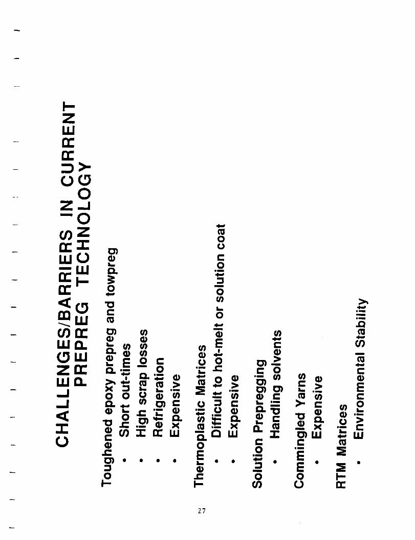
were unresolved matters. In this investigation, tow bundle twisting was used
to reduce the separation of filaments, tow-to-tow abrasion, and fiber loss.
Optimal weaving protocol was established and mechanical property
data were obtained for the consolidated woven material. Utilization of
appropriate textile techniques for composites processing is an important factor
for automating the production of quality composite parts from powdered
towpreg.
24

>-n'o_C_O0
ILl
O0I_n-'U..n
Wn-n'nn i.1.1
O nI-
n-
II
i._
iim
C0
"_0m
0,-.
_o-.om
m
ooo-._._"oZ
t- ,-..- o
o rt-m
0 >,
-,I
--iiim
x
I-- Z
c" c"
,1=
25

I._
O
U)U)
0L_
a3L_
I._a3
0
C_
C:
a3
C:
U)
a3
0L.
a3
L_
Q.0L_
C:
U)C0
:::3
C:0
• • • •
26
0 r- 0 0 I--I-- I-- or) (.) n-
27

D:tU£:)
0£). l--
ILl
0
I.IJ
t--
-I
0F-
WI.IJ
I-O0
O0 _ __
__ 0_ _I_ I--0 IZ.Z--I- _- _ o __Lu
W_l_ _j m Q w _:• a. I- In _ 0 __
U'O o > _ z_0 0 0 ma.
Z uj 0 > n.- w _-
I-'-, _ _ m 0 o0_C: z -_ tu0 _ _ _ m __
0::0--, O0 O: _ ,,_ 0,, ::::)
uJ Z tUC)LU n. 0 _: O:LU
0 Z _ n._c
28
LLuJQ:
LUC:).
_CF-.J
o.
o_Z
0
f-ZUJ
..JM
U.
z_
ILl..J
XILlF-
LL0
0Z
u.I00
I-
in o
o m
tu I--0m £:) _n.
tu Z_z_ n: o,el:£I: tu0 0 I--0
It. --J£]:
n-_ uj 0n_£1: -Ju.Ujl_ I:]:)t#J
o.l-- _£).

w>
0 o1.1.1 L
QI.LIm

O_'*_"_'_-kPA_E IS
OF POOR QUALITY
-- 3O

31

-1- 'I
Iii > 0£::1 V-. ,_N o oO "-J D.
O. O ,_
32

0I-
I I I I
33

C/'Jor"LI.II-'-LU
34

n
£0>-_J
Z,,_
#;me
0immm
..C
Et_
v
.C;3)
m
IX:
,I
r.. r.. o _ rno Q Q Y"l I-
tO 'el" _ I',,,_ _ _ At)
• CI _ • •CO CO 0') 0
0") 0') C_ 0")
IJ. 0 x x x x x
0inn
0!-
m
im
amh-
0
X
0
n immmm u m n
I-- I-- I-- I-- !--I I I I I
0 0 0 0t_ or rr n-_t _t _t _t
m
Q.
I
0 0t_ t_
_0 _0
,.. ,.. _,.. ,..
35

• • •

O
Em
c:n,,o,,_
"_ ..Ir..4)
I--
0 0
0_
m
"O
OI-
-t-I -tl
03 O3
03
OlD
¢D
.3'7
0
38

• _ 0m
ll
39

V. ATP ROBOT HEAD
November 27, 1991
Memorandum
To: N.J. Johnston, R.M. Baucom, D. Sandusky and M.K. Hugh
From: J.M. Marchello/_%
j
Subject: ATP Robot Head
In conjunction with our studies of towpreg
ribbonizing and on-the-fly consolidation, we need to
consider the design and operation of the ATP robot head.
The following summarizes my observations during visits
to McAir, Hercules, and Cincinnati Milicron, and what I
have picked up from literature references.
Advanced tow placement, ATP, utilizes robotic
technology to position the tow laying robot head on the
tool/part surface, and to move it over the surface in a
controlled manner, as an array of towpreg ribbons are
laid down. Spools of towpreg ribbon are held in a creel
on the robot and fed to the head. The robot computer
software system governs the ribbon placement process.
ATP robot heads are capable of in-process
compaction, individual tow cut/stop/start, resin tack
control, differential tow payout, and tow tensioning.
During tow placement, for each tow ribbon:
The ribbon passes first between two wheels, one
spring loaded and the other driven by a small
electric motor. This system can provide brake/drive
tension of up to 15 pounds (6.8 kg). As the robot
head moves, towpreg ribbon is paid out from the
creel spools at a tension level established by the
brake/drive motors. During straight laydown runs,
all tows are subjected to about 1 pound (0.454 kg)
of tension. During turns, braking pressure, and
correspondingly tow tension, is increased
differentially on the inner tow ribbons to slow tow
payout. For a 24 tow head, wrinkle free turns with
radii as small as 5 inches (12.2 cm) are possible.
A knife tow cutter/clamp system is used to achieve
tow ribbon drop/add capability. In this way the
number of adjacent tows being laid may be decreased
or increased to accomodate changes in tool/part
geometry. When a tow is dropped, the cut tow is held
4O

(clamped) by its tension brake. To add, or restart,the tow ribbon, the brake/drive wheel is driven(negative braking) to push the stiff towpreg ribbonforward onto the tool/part surface. To join thetowpreg array ribbon tape, the pushed ribbon mustbe picked up by the roller. That is, the pushed tapemust not twist or move out of line and must stayclose to its neighbor with minimum gap. The tow pushdistance may be several inches.
With thermoset towpreg, a tack control systemdecreases or increases the "B" stage prepregmaterial tack at critical points along thecut/clamp/restart operation in the robot head. Toachieve this the tow ribbon is passed over heatedand cooled surfaces. When a thermoset tow isdropped, the cut, hot, clamped tow may gel and stickto the heater/cooler/clamp/cutter surfaces if notrestarted in a few minutes. This requires shutdownand cleaning of the robot head mechanism.Thermoplastic towpreg does not require this system.Not having to handle tacky towpreg eiminates the towheating and cooling system inside the robot head.
As the tape of adjacent towpreg ribbons are laid onthe tool/part surface, it is heated and then compactedby a pressure roller. The hot gas, or infrared heater,and the roller are attached to the robot head and followalong behind as the head moves. The pneumatic pressurecontrolled, elastometric, compliant roller can conformto convex or concave surfaces, having cross band radiias small as 6 inches (15.2 cm) , and apply even pressureacross the width of the roller.
The following figures illustrate the robot head
internal mechanisms, under the hood operations, for
thermoplastic towpreg ribbons. Also shown are the changes
that might be made in converting from rectangular to
triangular towpreg. The changes deal with use of grooved
brake/drive wheels and an alternating up/down tape array.
Not shown are the heating and cooling surfaces used with
thermostet towpreg.
41

Towpreg
Spring LoadedRider Wheel
Brake/DriveWheel
MagneticControlled
Knife
DGuide
CROSS SECTION VIEW
Tool/PartIra, Surface
Tows From Creel
Motor Brake/Drive/ClampSystem
' uiil,I I !'1 I • Array Ribbon Tape
Tool/Part Surface
TOP VIEW
SCHEMATIC VIEWS OF ROBOT HEADATP TOWPREG RIBBON CONTROL MECHANISMS
4Z

SpringLoaded
RiderWheel
Brake/DriveJWheel
EPZ//_-,qu---Towpreg Ribbon
Brake/Drive
Motor
Rectangular Towpreg
__.,C MagneticontrolledCuttingKnife
V
I
II
Ii
Magnetic
L_ _,Controlled--Cutting
_ Knife
Towpreg
Rnbbon
Up/Down Adjacent Triangular Towpreg
Front View of ATP Robot Head Mechanisms
43

- Vl, ADVANCED TOW PLACEMENT REVIEW
November 13, 1991
MEMORANDUM
To:
From:
N.J. Johnston, R.M. Baucom, T.L. St Clair,
J.A. Hinkley, J. Nelson, T.H. Hou,
D. Sandusky, and M.K. Hugh
J.M. Marchello
Subject: Advanced Tow Placement
During the past few months, in an effort to obtain
background information for our study of advanced tow
placement, I have reviewed literature on calendering,
pultrusion, tape laying and tow placement. This study
also draws on the review of consolidation presented in
my August 27 memorandum.
The objective of this review was to learn about ways
to prepare towpreg ribbon for tow placement, to identify
potential improvements in the tape laying robot head, and
to explore ways of carrying out "on the fly
consolidation" during automated tow placement.
The purpose of this memorandum is to share with you
the information I have and my observations. Your
comments, particularly in regard to missing information
and misinterpretations, would be appreciated.
44

JMM11/13/91
ON ADVANCEDTOW PLACEMENT
I. Introduction
II. Calendering
III. Pultrusion
IV. Advanced Tow Placement
V, On the Fly Consolidation
A. Introduction
B. Consolidation
C. Heat Transfer
D. Voids
VI. Observations and Recommendations
References
45

I. INTRODUCTION
Advanced tow placement, ATP, utilizes robotictechnology to position the tow laying robot head on thetool surface and move it over the surface in a controlledmanner as the towpreg ribbons are laid down. Laser,infra-red, or hot gas heating and roller pressure areused to attach and partially, or fully, consolidate thematerial as it is laid down. If consolidation is notachieved "on the fly", the part is placed in an autoclaveto complete the consolidation.
The mechanisms of resin flow, fiber movement, andconsolidation, that occur during ATP are similar to thoseof the more established technologies of calendering,
pultrusion, and tape laying. Therefore, these processes
were reviewed as a means of understanding ATP and perhaps
contributing to its theoretical background, and of
obtaining information for devising experiments that may
provide needed information with which to improve ATP
equipment and process operation.
46

II CALENDERING
The process of calendering, or pressing betweenrollers, was developed over i00 years ago by the rubberindustry. It is widely used for tire-fabric coating, forproduction of floor tiles, and for coating paper andfabric with various thermoplastic materials (PVC,asphalt, polyethylene, cellulose acetate, etc.).
One of the first theoretical studies of calenderingwas made in 1950 by Gaskell (I) who modelled throuqh the
thickness resin flow for both Newtonian and non-Newtonian
fluids to predict shear stress and pressure gradient as
functions of the roller nip gap, roller speed, and resin
viscosity. In his 1974 patent, Ancher (2) draws upon the
theory to describe apparatus for impregnating fiber webs
with molten polymeric materials, see following figures.
Figure 2a illustrates the hydrostatic pressure profile
showing a peak of I00 atmospheres just in front of the
roller nip area.
In the 1974 patent, Ancher observes that it is
extremely important to avoid formation of air bubbles in
the composites because they become voids in the final
composite. Voids cause serious reduction in the
mechanical properties of the composite by acting as
stress risers. "Thus the embodiment of the process shown
in fig 3, when applied to high strength filament warp,
can be operated to maximize the air rejection ability of
the roll nip. This is done by operating with the minimum
nip openinq commenserate w_th the thickness of the
filaments and by havi_q a fairly larqe amount of fluid
surface at points 26 and 28 exposed to the
atmosphere".Interestingly, in his earlier (1972) patent,
Ancher (3) describes the air bubble circulating flow in
the resin buldge and discusses using a flow obstruction
to reduce air entrapment, see fig 3 and item 26 of fig
7 and discussion in the following page.
In a recent review of calendering Tseng (4),
addresses current processing concerns dealing with
temperature and pressure variation along the roller
length. Calender rolls are relatively long and are
constrained at their ends by bearings. During processing,
the relative pressure produced by the polymeric flow can
bend or deflect the rolls and cause a non-uniform gap,
known as the bending crown. Obviously this effects the
flatness and uniformity of the sheet. Another important
observation is that sheet speeds range up to as high
meters per second, which means pressure is applied for
47

about 0.01 seconds.
In their progress report a few months ago, Foster-Miller, Inc. (5) developed a theoretical approach to h_i_shear prepregging. As shown in the following pages, their
die process is essentially calendering with through the
thickness flow, fig 15. The model is applied to LARC-TPI
and indicates that pressures of 1,000 psi, and flow times
of up to 20 seconds, are required for impregnation. They
conclude that to achieve through the thickness
impregnation in one second requires resin viscosity lessthan i0 PaS.
Essientially the same theoretical analysis was used
by Seo and Lee (6) to model resin impregnation in
thermoplastic composites. Their through-the-bundle press
experiments to validify the model used PEEK 150P, see
following pages. Viscosities ranged from 300 to 800 Pa-
sec and impregnation times were from i0 to 30 minutes
depending upon temperature and pressure.
In closing this section, it seems appropriate to
comment that powder coated tow requires less resin flow
for consolidation, since resin particles are already
distributed within the fiber tow bundle. It would be
interesting to repeat Seo and Lee's experiment using
powder towpreg. Also, the Foster-miller die might be
capable of handling high viscosity resins in one second
if powdered towpreg were used.
48

i,__ PAIENIL,.::_v19_7_ 3.849. IT4 _ ,
w
_rLrT 1 IF 3
F
SOuo WEB
u
1" I m"a_s,_£,,_"$• (_.-I00
I
49
,'P,_E ISOF POC_t QUALITY
EJm,
;) "1 '_"

._- PATENTF..,,_;:_v191974 3,849,17,4' IHI_I 2 OF3
50
:.,p
t
i
A
_tw

/
3,849,$
_mproved flow and procesz control for making foamcored sheeting.
Embodiments of the invention arc shown in FIGS. 3
through "1.Referring specifically to the apparat_ of FIGS. 3 and 5
4, an extruder die 10 is provided having a shape whichwill project into the bank of material which would oth-erwise form between counter-rotating rolls 12 ,,rod 14of a calender. The die !0 extends acro_ svbstantiallythe full width of the calender and has inter_J manifold 10
passages 16 and 18 which receive molten, polymericmaterial from extruder 20 and feed it through die pas-sages22 and 24 to the pace,ages 26 and 28 formed be.tween opposite sidesof die 10 and calender rolls 12 and14. 15
Die 10 is also provided with a substantially axial pas-sage 30 which permits the feeding of laminating sheet32 directly to the nip 34 of the calender, between thetwo outer streams of molten, flowable polymeric mate-rial entering the nip through passages26 and 28. 20
Additional webs or sheetsof material 36 and 38 mayoptionally be fed, if desired, to the outer surfaces ofrolls 12 and 14 to provide an outer surface for the re-sulting laminate 40.
The central laminating sheet, streams of molten, 25flowable polymeric material, and optionally outer addi-tional websare all continuously fed to and combined bypassagethrough the nip 34 of the calender to providethe resulting laminated polymeric material sheet 40.
It is, of course, to be understood that volumetric oh- 30struction die 10 is maintained across the full width ofand between calender rolls 12 and 14. It has beenfound that the most forward (downstream in the direc.
tion of material passage) projection of the obstructionshould be positioned soas to at least penetrate the bank 35of material otherwise formed between the pair of calen-der rolls upstream of the nip by the selection of calen-dering conditions.
It has been found preferable that the most forwardprojection of the volumetric obstruction be positioned 40well within the space between *.hepair of calender rollsbeyond the position of merely slight penetration of thebank of material being calendered. However, any posi-tioning of thJ most forward projection of the volumet-ric obstruction (within such penetration of the bank) 45between the rolls will provide a signifcant reduction inback flow and consequently improved calendering re-suits.
It is most preferred that calendering operations beperformed with the obstruction maintained at a suffi- 50ciently close distance to the nip to substantially reducethe calender back flow and thus eliminate the naturalbank rotation typic, d of conventional calenderingbanks. Thb has been found capable of accomplishmentby substantially contouring and positioni tg the volu- 55metric obstruction witl-, the stqnifion rome or area ,,-defined in my copcnding application Ser. No. g39,292.However, as pointed out hereimtbove, thb contouringand pmitionin$ LIby no meam critical and the desiredresultsare prolFemvel $. accomplished as a more sub. 60
SLllathdporth_! of the back-flow zone becomes occu-pied by the volumetric ohctruction.
As mentioned hereinabove, it is optionally within the
purview of the _£-sent invention to introduce webs 65(same or different kinds) along the two roll surfaces,thus enabling the forming of complex comp_ite lami-_ ina sinlle_II p.=. T_ webs appli_lak_ the
1746
roll surfaces may be selected for decorative purposesand in addition to th_ web materials alrc:,dy men-tioned, decorative webs such as wood veneer, cork,
embossed or engraved metal foil, burlap, printed orotherwise patterned paper, natural or synthetic fiberfabrics, etc. may be used as exterior surfacing for thefnal sheeting Furthermore, the flowable plastic mate.rials introduced through manifolds 16 and Ig may hesupplied by individual extruders or other melt pumpsand thus provide laminates with different plastic inter-layers. Similarly, the laminating web 32 introducedthrough passage 30 may itself by a multilayer compos-ite thus resulting in the formation of multilayer com-pc_ite laminates 40.
Another embodiment of the invention, as shown inFIG. $, I_rmits the same result to be obtained solely bythe use of a four roll calender. As there shown, a calen-der is provided having rolls I 1, 12, 13 and 14. Thestreams of flowable plastic and laminating webs are fedto the calender, through die !0, as in the embodimentof FIGS. 3 and 4, whereas the optional additional outerwebs 36 and 38 are fed in the manner shown to the
banks of material between roll pairs 11-12 and 13-14.The laminated polymeric sheet 40 is produced in thenip between the 12-14 roll pairs, as in the case of theembodiment of FIGS. 3 and 4.
FIGS. 6 and 7 show an embodiment of the invention
employed for making foam core laminates.As in the case of RGS. 3 and 4. additional exterior
laminating webs 36 and 38 may be introduced alongthe surfaces of rolls 12 and 14. Also, it is apparent thatthe embodiment of FIG. $ can be changed to producefoam core 41 sheeting by providing an expandable plas-tic material instead of laminating web 32 through thepas_ge in flow obstruction 10. In this variation it be-cc.xtes possible to manufacture foam cored sheetingand !amJnates directly on a conventional calender.
The flow system of the present invention conve-niently circumvents the air rejection phenomenon of aco'wentional calendering bank referred to earlier. Theexpandable material in the center stream is enclosed onall sides and under elevated pressure until it has tra-versed the roll nip. Even then, the sheet surface con-sist_ of non.expandable plastic material and the gas isthus effectively trapped enabling the most emcient uti-lization of chemical blowing agents or injected gases.
A type of laminate which i_ becoming increasinglyimportant Is continuous fiber pre-prelp (pre-impregnatr_ filaments) made from high strength, highmodulus filaments such as graphite, boron or gla_.These pre-prelP are webs of very accurately alilnedand spac_l filaments which are supplied to a coatingapparatus as a warp, i.e., without any tramve_e ilia-meres (ill:in I or woofing). The polymeric coating isusually an epoxy or pobimid pre.polymer which is B-staged or advanced sul_quent to the impregnationstep. The tape= are then u_l for building up contposit=su_ctures for ubra high strength parts such as stmc.nu-al =dr Jmd spm_ craft memben by aligning the fibersIC¢ordinll to the dit,eet_n of the zppl_,_i stresns. Alterfinal lay-up, the _ are freed tolffd_ andcured by autodavin¢
It is extremely important to avoid fommtion of =drbubbles in these c_tes because they becomevoid= in the final ¢omporate which cause serious reduc-tion in the mechanical properties of the om'_npomtebyL_tinll m mere r=iw,.nc Thin, the emtxxlimem of _e
51
\(
/

April 2_, 1972
_iled July _. ]_g
F. H. ANCKER _,_,U/_
CALEND_RIN_ OF FOLYMERIC _ATERIALS
4 Sheets-Sheet |
F/G. 3.
P
P
F/G. 4.
..... :.::..
•, :.. -,:..-,. :-...iI @ le lOo • e o Dql o o o _ •
,1:...-...'..:........•_ee eel • • e °
I_'.'o'-:::: ;- ".:;o_." _• • I • • oO@o ,J,9"_
t I I i tl
Ill I ii
52
INVENTOR
FRED H. ANCKER

T"
April 25, 1972
Filed July 7. ]g_g
F. H. ANCKER 3,658,978
CALENDERING OF POLYMERIC MATERIALS
4 Sheets-$hset
I
r
F/G. 5.
281./ -- 1 I
24 __.
"/4
.12
I"1" 6
k
* i
s _
: i
:' FIG. 6.:iI :
! ,
a ,
f36
p
F/G. 7.
53
INVENTOR
FREO H ANCKER
ATTORNEY
F

3
3,658,9784
tern or the actual calendering bank shown in FIGS. 3 and
4.FirsL the maximum thickness limitation of about 25
mils for runs; calendered shctting is due to the reculiar
air entrapment and rcj.'ction beha¢ior of a natural cal- 5endering bank. We have found that air bubble." atmostinvariably are introduced into the calendering b_:_k wherethe hot sheet moves into the bank (points P on FIGS. 3and 4), no matter in _hich direction the bank is rotating,If the bank surface is fluid and glossy, this tendency is
generally less than when the bank surface is dry andmatte, but some air is nearly always introduced. If thebank is cold and "foMing." additional air is often intro-duced due to air cavities between the folds and due toformation of secondary vortices. Nevertheless, as long as
the nip opening is small, the stagnation surface is 'veryclose to the roll surface, atr becomes trapped within thestagnant flow zone and has no opportunity to pass d'.-uthe roll nip. Accordingly, it is often seen in calendering ofthin film,, that the calendering ba_k is fi!led with air hub.-
bits, yet the emerging film is completely free of air. How-ever, as the nip opening is increased in order to producethicker sheeting, this fortunate situation no longer exists.
opening of a pair of counter-rotating c:-lender rolls v,hilemaintaining a volumetric obsttuchon actors the width
and betv, een said pair of calender rolls, with the mostdownstream projection of said cbstruction being poet-tinned so as to at least penetrate the bank of matertal
formed between the pair o[ calender rolls upstream of thenip by the s_-Icction of calendering conditions, and v.hl]¢concurrently feeding a stream of polymeric material tosaid nip opening on each side of said volumetric obstruc-
10 tion.The present invention provides a simple and effective
solution to the above-mention¢_l and other problems in-
herent in the calendering process. The solution to thisproblem is affected by removing a substantial Fare of the
15 stagnant flow zone by placing within this region of flowa volumetric obstruction, while at the rome time introduc-
ing the polymeric fluid in the form of separate streamsconforming to the active or progressive flow zone, i.e.,one stream on each side of the obstruction. The flow
20 obstruction substantially reduces the natural back flow in
the calendering bank and thus makes i,, po_ible to reduceor eliminate the usual bank rotation with its associated
problems of air entrapment, thermal degradation, sensi-
The stagnation surface will recede from the roll surfaces tivity to surface defects, etc. In fact, the present inven-and the roll nip, the air bubbles introduced at point P 25 tion makes it possible to calender film and sheeting ofnow will be captured within the progressive or active flow excellent surface quality on a two-roll calender or millzone and the emerging sheet will become porous and/orcontain air streaks on the surface and be comma:tinilyuse[as&
Second. the problem of polymer decomposition en-countered in attempting to calender thermally unstable,
yet highly viscous, materials is also intimately connectedwith the nat,_ral flow pattern of a normal calendering
bank. As the roll speeds increase, the residence time ofmolten polymer in the progressJ_,e zone of the bank de-creases: however, the residence time of the polymer melt
within the stagnant zone remains very great. Actually, be-cause of the increase in viscous heat dissipation with in-creasing roll speed, the polymer within this zone maydegrade severely before any visible degradation occursin the emerging sheet. Thus, the stagnant flow zone withits associated extreme residence times is the major rate-limiting factor of the calendering process.
The shied ma_or problem of the conventional calender-ing r.roctss is the difficulty with _,'hich many polymermcits comply with the complicated film tracking and rollrelease required on a four-roll calender. The fact thatthreeroll passes are reqt.ired to produce a calendered
by direct feeding from an extruder using a suitably de-signed die. Also, the invention makes it possible to cal-ender much heaviergauge sheetingof a varietyof poly-
30 mars ou conventional calenders or mills by the use of a
suitably arranged obstruction.The invention is more fully explained by reference to
the apparatus embodiment shown in FIGS. 5 and 6. Asthere shown, calender 10 is provided comprising a pair of
35 counter-rotating rolls 12 and 14 and str;pper roll 16,Calender l0 is directly fed two molten polymer streamsill and 20 from extrusion die 22, v, hich comprises dmhousing 24 and flow divider 26. A str,a,"n of moltenpolymeric material 28 is forced from conventional ex-
40 tender means (not shown) and enters extrusion die 22thru inlet means 30. The polymeric ma,_eri:_l then passesthru passage 32 to internal die manifold 34, having twomanifold branches 34a and 34b.
Along the manifold edge, the molten polymeric ma-
45 teria; s,ream is separated into two streams by flow d;.',ider26 which, in its most forward projection 36, a_o see,caas solid volumetric obstruction. Because the forward pro-jection of the flow divider (volumetric obstruction) pref-
sheet of acceptable surface quality is, of course, the un- erably occupies a substantial portion of the back-flowderlying reason for this limitation since tracking on a 50 region (stagnant flow zone), smooth, gently curved bankto, o-roll calender generally is quite simple. In studying surfaces Iga and 20a are formed between tl'e die lips and
the calender bank flow of many polymeric materials, ithas been consistently surprising how seemingly minor flowdisturbances on the inlet side of a roll nip often causevery objectionablesurfacedefectsin the sheet emergingfrom the roll nip. This phenomenon, which undoubtedlystems from the elasti, memory typical of high polymermelts, is believed to be responsible for the redundancyrequired in convention: ,r catsndering. In other words, theflow history, melt tempcr_ cure, etc. within a calenderingbank is not sufIiciemty ,niform to obtain a high qualitysheet unless the process is repeated at least once, usuallytwice or _metimes even three times over.
It is, accordingly, the prime object of the present in-vention to provide method and apparatus for the calender,
ing of p_lymeric materials in which material thickness,
degradation and surface defect limitations are greatlyminimized or eliminated.
Other objects and advantages of the present inventionwill be apparent from the following description and ap-pended claims.
In accordance with the present invention, method andapparatus are provided for the calendering of polymericmaterials wherein said materials are fed thru tht nip
54
the roll surfaces, as shown in FIG. 7 of fl',e drawings.It has been foucd that the forward projection of the
flow divider (volumetric obstruction) does not have to55 conform closely to the particular stagnation surface re-
v,lting from a particular roll diameter and nip opening.Actually', it is preferable that the front end of the flowdivider is considerably more blunt than the theoreticalstagnation surface and that it stops scmewhat short of
00 the stagnation point. The reason for this is that the hydro-static pressure in the roll nip is low in the outer region ofthe bank, whereas it increases steeply near the maximumpressure point (FIG. !, x----x,). Con.,.equently, if thefront end of the flow divider (volumetric obsrtuction) pro-
($5 trudes only moderately into the bank, some misalignmentof the die can be tolerated.
Furthermore, a blunt front end ;s more tolerant ofoperation _ith variable relative roll speeds which, aspreviously mentioned, changes the shape of the stagnation
10 surface and thus the optimum position of the volumetricobstruction. On the other hand, if the front end of theflow divider is sharp and protrudes far into the roll nip,then the alignment of the die, i.e., volumetric obstructmn,must be very accurate in order to avoid undetirabla de,
71 necdoo= =,',d 11_ di=ttarbaam=m
I/"

_ff__-_-:-__--_The basic assumptions made in development of the
mathematical flow model are:
• The fiber bundle behaves as a nonlinear elastic porous media
• The aligned fiber bundle has u'ansversely isou'opic permeability
• The resin behaves as a Newtonian fluid during impregnation.
The viscous resin flow through a porous media can be described by Darcy's Law which states
that the flow rate per unit area, q, is directly proportional to the pressure gradient as described by
equation (I).
-S dpq- I1 dx
(1)
In this equation S is the permeability of the fiber bundle and _ is the Newtonian viscosity. The
permeability, S, can be described by the Carman-Kozeny equation. For this case the equation
shows the fiber volume fraction (Vf) dependence of the permeability.
S
(2)
f
ttere rf is the radius of the filament is the Kozeny Constant w_h describes the geometry of
the porous media in the direction of flow. From this equation it can be seen that as the fiber
volume in the impregnation zone increases the permeability, S, decreases. We have assumed that
the fiber bundle acts as a non-linear elasdc media, and as such, Vf is a funcdon of the applied
pressure (or stress on the fibers). The deformation behavior of the fiber bundle has been modelled
by assuming that the fibers behave as bendi_ b-earn--s-Fd_n multiple contact points as shown in
Figure 16.
3hEO=
4
From this thefoJi-o_ng stiffness equation can be derived:
= Ap
qo \",
01 (3)
uS'_,.._ !,di:. Contact No. NAS I- 19095
QU.4LITy
/

where:
AP
E
13Vo
Va
= applied pressure
= fiber bending stiffness
= state of the bundle as described in Figure 16
= initial fiber volume fraction
= Maximum possible fiber volume fraction
Q..t
/L-
Plotting the fiber volume as a function of the applied pressure as described by equation 3 we
obtain the curve shown in Figure 17.
Substitution into Darcy's law (equation I) to account for pressure gradients in the fiber bundle
during impregnation and integrating to x = h allows us to determine the time required to impregnate
tile bundle:
"(l'V )ho -t = 2 Ap Szz &L_) .iv, ,D" (4)
t _"_
Note that the applicatip/n of a large pressure gradie, m'is not necessarily the way to speed
impregnation since the ap_[_ pressure itl_ffects the permeability by increasing Vf. f--
Applying the fiber deformation model to the permeability function results in a modified carmen-
Kozeny equation:
}l't
Szz - 0
4 kzz _Va + 1
Vf
3
(5)
In equation (5) Vs' refers to the fiber volume fraction whegf the permeability of the bundle is
effectively zero (i.e., the bundle is pressed closed). This is an important point because the fiber
bundle is compressible therefore the permeability can go to zero before the volume fraction goes to
1. This point is not apparent in the unmodified Carmen-Kozeny equation (2)•
" '_' Qo,a_t2"r/
/
9
56
Contract No. NAS 1- ! 9095
Foster-Miller Progress Report

FOWgB;I_, INC.
Utilizing the rheolog), dab presented in the previous section and subslitudng into equations 4
and 5, theoretical impregnation rimes can be calculated for the various conditions. Table 1 shows
that impregnation times just over 1.5 min for LaRC TP! may be achievable. It is important to note
that the times in Table l are only valid for the assumptions noted, and no account for the polymers
shear stress relaxation has been made. It is also assumed that Beta=200 accurately describes the
state of the bundle at the time of impregnation.
ttolcling all variables constant and changing only the viscosity of the resin, the time to
impregnate would increase with increasing viscosity as shown in Figure 18. From this figure is
appears that impregnation times less than 2 min are achievable with viscosities as high as 600 PaS.
4,
4,
,ll
O
Ik
O
Conclusions
The rheoiogy and flow modeling results discussed above have numerous implications for
thermoplastic melt impregnation of a towpreg. Importantly:
• Xydar LCP can be blended with LaRC-TPI to reduce the latter's shear viscosity by
80 percent; this reduction becomes larger at higher shear rates
' • Based on processing and rht_ological studies with polypropylene, shear viscosities of 30 to
40 PaS (300 to 400 poise) or less are required for the polymer to penetrate the fiber bundle
within 20 sec or less _ . dLc_ ,_ L _-- .....b, )
• To reduce the LaRC-TPI shear viscosity to 40 PaS. at least 10 weight % Xydar LCP and
1000s- i shear rates are needed
LaRC-TPI and its blends with Xydar should be processed at high shear rates to reduce the
residence time in the melt, thereby limiting the consequent increase in viscosity; melt
temperatures of 350°C to 380°C should be used
Shear stress relaxation times on the order of I sec at higher shear rates (greater than 10 s-I)
limits the practicality of using high shear as the sole means of accomplishing high
performance TP melt impregnation.
OF POOR QUALITy
Confidential Proprietary Information
Concerning Foster-Miller, Inc.
10
57
Contract No. NAS !- 19095
Foster-Miller Progress Report

FO_CBIt-.II_LL_, INC.d
RESIN INTRODUCTION
P2
RESIN
FLOW
FRONT
0 t.
P2
RESIN INTRODUCTION p =p = RESIN PRESSURE1 2 IN THE DIE
Figure 15. 2"he Impregnation Model Adapted to tile lISP Die
F F
TI---L---I --Iol-
Geoaetty (o[ a Unit Dendln_ Ce|lUaed to Derive the St|f|net| of =
II'|belr |undle. Note that
the Pacanetelr |- L .
h'_f
Figure 16. Geometry for a Unit Bending Cell Used toDerive the Stiffness of a Fiber Bundle. Note
that the Parameter 13 = L/(h-dd
58
22 Contract No. NAS 1- ! 9095
Foster-Miller Progress Report

. (
Delta P
S' c_,.v. .,
(psi)
Not_:
E = 227(1091 Pa
10000000
1000000
100000
10000
1000
100
10
o I I I t I I
_ ,. _ Va = 0.785r _."
._ Vo--Q5
13=200 -
/
m
0.50 0.55 0.60 0.65 0.70 0.75 0.80
Vf
Figure 17. The Effect of Pressure on the Fiber Volume Fractlon
23
59
Contract No. NAS 1-19095
Foster-Miller Progcess Report

OOo
II.
I!
OO
U)m
n
OU
r-!
=iII
OcO
O
A
@
O
.G_F-
tJ)
We-_3tw
Figure 18. Increasing Viscosity Increases TimeRequired to Achieve Impregnation
24
6o
Contract No. b/AS I- 19095
Foster-Miller Progn:ss Report

r+.
co
3
,,v,
i
_ ,..+I
ZU..
!'/ e,,
:,4 "2
\--,
+,- __r.
/
L>IL__/ '.+
®
E+,..
0
CP,
s
Q.
ag
E®
e'- "_ _
6,=,vE_-_'
• i,..,
0
E_E
f-,,' .
I _,D +,...
!°
u.,_
__u.,
+i'+III
+,+.
<
JJ
--1
-1
• t',
.,,C+
r_
wJ
p_-4.1
.....>
¢1
L_
\ )>
0
(_>+s -+d) ,(l!soos!^
ORIGINAL PAGE IS
OF POOR QUALITY
0
'__}0
0
0

PRECEDING PAGE BLANK NOT F;LMEO
E H_ _
_ N ®
m
E__-. E
"_ 0 II 0
I0 _ _ _ •
OF POOR QUALITY
H
_uu

If
1 L _ r 1
q
(ulul) uoll_ullaJdull ;+l_.ldtuo_) Jo] attHl
o
P_E
Q.
Q
_._a
+!tj
l I | I I, I o
(tlltU) UOllltl|lpidtu| ataldtll+_l Jo| atJLlll
II
1" ,_+,
+
{tiltml l_Ofllelll.14tul ll.l+fclulo_ + .to I +u.lll
.+
i-"' _.
oo
+4
_.®
_ +,,,-
-++0
mm
m+m_
s
0
!
ml II III III I I I I I I I I I I II il I I I I I I
_.,P.
0
0°_
i t . I
-- m _ + t.,+¢_ o o o
uovll'u|+JduJl io +,_+Jl+(_
0
t_
0+
+
i!am
+;
i- m. _o. +. e+
uo!'l_ulh, JtlUJ I _o ++._+<_
¢1
!
_m
al I
.2

Res_
Buldge
Tow
Temperature
Preheated Tape and Hot Rollers
Temperature
re _g_Tm
hickness (voids)\
Cold Tape and Hot Rollers
NIP ROLLER CONSOLIDATION CYCLE
64

III. PULTRUSION
The computer model of pultrusion recently developed
by Lee and Springer (7) describes the processing of
thermoplastic matrix composites, and computes: the
temperature, crystallinity, pressure, and consolidation
inside the composite along the axis of the die; and, the
required pulling force, see following pages. For APC-2
(carbon fibers melt impregnated with PEEK) prepreg tows,
pulling forces range from 2,000 to 4,000 pounds at speeds
of 2 to 5 inches per second.
In an experimental study of pultrusion, Astrom,
Larson and Pipes (8) used APC-2 to determine the effect
of pulling speed on the mechanical properties
(compressive, flexural, and apparent interlaminar shear
strength) of composites produced with a rectangular
cross-section of 3.2 x 6.4 mm, see following pages. The
ribbon was preheated and pulling rate ranged from 1 to
4 mm.sec. Mechanical properties were independent of
pulling rate in that speed range.
Taylor and Thomas (9) studied the use of ultrasonics
to aid pultrusion of thermoplastics. They made ribbon
from a number of materials including BASF powdered
towpreg of E75 carbon fiber with PEEK. The ribbon was
0.89 x 0.05 cm, for which they used six of the 12k PEEK
powdered tows. At pulling rates of 1 to 2 m/sec the
pultrusion ribbon contained less than 1 percent voids.
Information about the die is not given, but if it were
0.5 m long, the pultrusioD cQnso_dation times were
between 0.25 and 0.5 seconds.
In their discussion, Taylor and Thomas observe that
"while ultrasonic activation of pultrusion dies has been
shown to reduce die friction for thermoset pultrusion,
the goal of the present work was to develop alternative
methods to enhance consolidation rather than simply
reduce friction ... since ultrasonic flow promotion is
directly related to the power input to a power level
determined by the specific resin, the ultrasonic power
is generally not varied but maintained above the
threshold for flow promotion and below the level leading
to polymer degradation",see following pages.
Batch (i0) analyzed temperature, cure, pressure, and
pulling force for pultrusion in his PhD disseration. He
developed mathematical models for (1) resin backflow, (2)
thermal expansion, shrinkage, and compression of resin,
and (3) the compaction of fibers. The pressure and
65

pulling force model was used to study the taper geometry
at the die entrance. In his resin backflow model, Batch
accounts for the difference between axial flow through
rovings and through individual tows. The thermal analysis
allows for thermoset polymerization and shrinkage with
separation from the die wall in the release zone, see
figure 10.12 in the following pages. His pulling forcemodel includes bulk compaction traction, viscous
traction, and frictional (fiber-wall) traction.
In his model of fiber deformation forces in
composite processing, Batch draws on the work of Gutowski
and of Gauvin and Chiboni to develop a "fiber contact"
approach. Examination of experimental pulling force data
indicate that viscous drag alone does not account for the
measured forces. Friction between the moving fibers and
the stationary die are the dominate component of the
pulling force. Batch's model suggests that the greatest
frictional resistance occurs after the resin gels(thermoset) at the wall and before it shrinks and
separates from the die.
As part of their work on injection-pultrusion
Kincaid, McCarthy and Fanucci (ii) obtained pressureversus fiber volume in the absence of resin for several
fiber orientations. The behavior of dry material is
somewhat different from that of prepreg, see following
pages. Stress relaxation times are about i0,000 seconds
for random mat and 0/90 cloth and they are about i00,000
seconds for unidirectional straight rovings.
Fanucci, et. al. (12) developed a thin, disposable
pressure sensor to monitor through the thickness
consolidation forces during composite processing. Their
data support Batch's predictions for thermosets, see fig9 of the following pages, and indicates the importance
o_ temperature in reducing consolidation pressure for
thermoDlastics, see fig ii of the following pages.
66

E -
-.. &_,.S = '.4,..,+
r_
_ ' \/
: !./I
! ! ! ! "= = =
(._,) 1 '_Jnleua(Im_j. _ '_ll_U!lltlS_J3
iI
jttw
/i
I
• i
e
_)d 'U°!leP!l°SU°3JOaaJ|a(!
=
=gieL-
\
N
; I
I !(.Jql)a:)JozilU!llnd
_D
.C.
L
_
.._ t
t2
e_
E8
N o
t_
_ 8
_ > __8 =
e
__ _
..= '_ '_ _ e-, .=_,, ._ .-_ 8 8 - _._ _
_.._"
- ._ __ -_,_
_. _ _ .., :_ e-' ._ "-:- -, _,. ,, - _ '-
_: _ .__ "4 E-, 8 .4 -
' "C)
LL
L
OF PO0_, QUAL!TY
67

r_
0
.<
,.., 7
6
r_o
r_
o
.%
D -_ __ _. x
=8 _ "_ __ _ =
._ "-' .=, *_ _ ._,
v _,
Z
<
z
0
o
2, -
I _ I _ _ _" =
II _ II If ,-; Ii I1
-_ _ =
.
.__
_=_-.__ _ _
• _; _ -.-'
_
_ _ o_ __.
._- _-_ _ ._-.._.-_..
= _ _ .-
.-_ -_ _ _ _ ._ .__ 8
o _ -_._ _-_ _ _
.o _. _]_-_!
&._ _ _. _ _.o
•- ._ _ _ _
-_ _
/
////
/ 4
\
@%


I
i
I
i
/U_r- .._
_E
n
u_
6=_
I

ORIG_N,_L P,':.,_E !_
OF POOR QUALITY

G_ P,.":O_ QUALITY

L ..... °l'o o
_ , i, t i l_ •
:>- E _ E
14
i uIJ
f.p
u'1
it.
>_L>
___ ,;,;
J z--4,_i:.
!> _ _
8
]i
73 _ ._

>,
:> O,
z _
8
0
,_ g o o
z
W 0
= o § _ o0 _ _3
"_ _ -_ ._m
0
Jr"
_Z
odol_74 b_

Pl
O
9u
U
8
3m
LI
M
_ ° _w
_°
u Bg
_ EoO
u _
•-__ _ _U _
"_ Q .-_
o _ _'7
-,',"_.'_01_ OU_,Lr'_ "_'


¢"1
gg-Ig
E3
| o
/ "...,_/ -tf
>'/ i" II. t II g _ I
/ _' iI>"
j/;;/
• ! • i • ! • T •
-: d d d d
uo!l_r,J:l omnlOA J_l!:!
"53Iu
E ,9.oo
f-

f'l
z
f;i- l,;'Og,i,l _UAUTY

Young Roalc Ktm, Stephen l'. McCarthy. a11d Jerome P. Famicc[
,mek_
j Cl_lh+l¢ks
:'""t' ' ° _o,+. _°_'nlm_l+°n +islm fin'
surfaces are generated both by compaction of lhe
relnforcln_ fibers and pressurization of the matrix
malerlals. 13orb of fee.Is act to Increase the total pull-
In R force required to move the product through the
die (2} In the InJec'llon-pultruslon process the rehl-
fnrctng fibers are dry as they enter tim die. Therefore.
nn ly fiber c.ompactlon c.ontrtbutes Io the pulling force
that arises Its the compression region of tlm dle. The
nblllly to predict the pulling load associated with tire
r'_+llSp,'lr'lloll OI arbitrary combinations of rehsforclng
islalerlnls Is essential for proper design of Injection-
ptdtru_lon tooling, machine size selection, and prod-
uPS design.
Tim maln propose of thls study Is the generatlon
of a data base of compressibility Information for a
variety of fiber reinforcements of Interest to pul-lrllders. This Information will be used In tim devel-
opment of an analytical model of the InJectlon-pultru-
shm process. Tiffs paper will present results of an
expethnenlal and analytical Investlgatlo. of the re-
spouse of various dry reinforcing materials subjected
In compressive forces applied normal to their princi-
ple plane. Stress versus fiber volume data generated
during tests of both Individual materials and variouscombinations of reinforcement will be Illustrnled.
Dlsctmslon regarding compressibility and relaxation
behavior of fiber reinforcements will be presented.
THEORY OF COMPRESSION
Tim consolidation of composites has been studied
by a nmnber of Investigators. Among them. Gs,towskl
[3-7) has published extensively on the subject. Ills
research has su_.,gested that the fiber network can be
+4 Oi,+'._,:_!?J/:,,L _:+/.C£ I-3 79
nF F'O0_ QUALITY
modelled as havh_R the followhll_ characteristics. AIor below a certain Initial fiber volume fractlot+, t'+.
the fibers carry no load. As fiber volume fraction. V,.
Is Inc.reased. the network can carry a rapidly Increas+
log load. Eventually. the fiber volume frac.tlnn of the
network approaches a theoretic.hi nlaxlmutn ba_cd
on close packed geometry, and can not h+c.rease with-
otsI an enormous Inc.rea.ce In load In thls reglon. Vr
approaches a maxlmtmn! available fiber voltm+e frac-
tion. V,,, When the fiber nc.twork Is perfectly alll_ned.
V,, Is almost always between the Ihnlts for a square
array. V,., -- 0.785. and a hexagonal array. V,,, --
0.907, Gutowskl developed a nmllsematlcal exprcs-slot+ for the transverse stiffness of a bundle of cms-
fined, approximately aligned fibers by assumlnt_ lhnt
tim fiber will be sllghlly arched so llml tim appliedload comes to rest on the beam secllon belween mtd-
Ilple contact points, and not on lhe end palnt,r. The
stress taken by the fiber network In bending Is then
= A, (I)
where A, Is a constant dependent on tlm geometry
and properties of the flber network wlthln the ply.
F.quattotl I assumes some transverse fiber re-
arrangement during compression, lie expressed that
E
A, = 3_r 8-_ 12)
where E ts the bendln R stlffnes_ of the fiber, and fl
Is the typical span length/l=c.lght rallo for the fiber
bean! network. A computer program was t_sed to find
the three variables {A, V,, and Vo] that produced thebest fit to the data.
Another approach to modeling tire compressionbehavior of fibers was taken from tim field of soil
mechanics [8.91. This theory assumed tirol the voids
were completely filled with water, that both the water
and the solid constituents were perfectly Incompres-
sible, that Darcy's law was strictly valid, and that
tim coefficient of permeability, k. was a constant.
Taylor (9] used a model of a spring Immersed In a
water cylinder. A frlctlonless and tightly fitting pls-
ton was placed in the cylinder and loaded with
weight. The piston was provided with a stopcock.which was assumed to be closed so that no water
could escape. When the stopcock was opened, tim
water flowed out due to the pressure with which It
was subjected. In the first Instant, the pressure con-
dltlons were unchanged. As the water escaped, the
piston moved lower and lower, compressing the
spring The spring, consequently, carried more
weight, until finally It carried all the weight. The
lenglh of time required for the spring to supl)ort all
the weight depended on the rapidity with which thewater escaped, that Is. on the size of the stopcock
opening If the spring were more compressible, more
water would have to escape In order to produce a
POLYMER COMPOSITES, FEBRUARY 199I, Vol. 12, No. t

1
1
CompresslbtlIl y arld Relaxat ion of Fiber Retnforcemertts
given change In consolidation. Consequently. a
longer tlme would elapse. In the mechanical analogy,
tile spring represented the compressible fiber reln-
forcements and the water In the cylinder represented
the resin In the vold space of fiber network. An
empirical relationship between fiber volume fraction
and effectlve stress was expressed as follows:
Vf = V, + C_ log,o(_/_,) (3l
where _; was usually taken as unliy 11 psl or I kg
per sq.cm), and C_ was called the compres._lou hldex
or expanslou Index. Vt was the fiber volume fraction
wheu the effective stress, o, was unlty.
TIIEOR¥ OF RELAXATION '_/'
The phenomena of relaxatlou of fiber reinforce-
meiHs durh,g compression can be explahled by theMn×well-Wlechert viscoelastic model (10), which con-
sills of au arbitrary number of Maxwell elements
ram,acted In parallel as shown In Fig. 2. In each
element, the modulus, E, characterizes the response
of the sprh|g while the viscosity of the liquid tn the
dashpot, _. defines the viscous behavior. Front here.
relaxation thne, T,(= n,/Ez). Is determhted. During
compression each fiber Is stressed. If we assume that
all fibers act Independently, we can describe the totalstress as the summation of the stresses of the lndl-
vldt, al elements.
In a stress relaxation experiment, one compresses
the sample Instantaneously to some strain, fo, atld
sit,dies tile stress, ,7(t). necessary to maintain theconstant strait|. The Instantaneous strain will be
realized only In the spring element. The dashpot will
El E2 E3 E4 E.';
q I q2 q3 q4 q5
Fig. 2. Maxwell-Wiechert model for relcL_aHoa|.
gradually relax so that the stres._ decrease_ a_ a
function of time. In this model the sprhlg reprcse||ls
the compressible fiber reinforcements with a sprlrlg
constant related to the elastic properties of the fiber
and the matertnl geometry. The dashpot represents
the structural rearrangement of fiber and/or break-
age of fiber durhlg compression. From this model wecan describe
o(t.___!]_- o(O)___le-'" + alOI-----2e .....' + a(0)-----23e ""_1 (Tf 0"¢ tT r
+ ... a(O)__,e-"'- (4)_t
r_
-- E 0(0}, e-'"P'= t drl
where .(0},, Is the stress on the nth element at thne
equals zero. and _r, Is Inttlal stress applied on the
sample. Thus, the total stress relaxation Is the sum-
marion of the responses of the Individual elements,
EXPERIMENTAL PROCEDURE
Compression Test
Materials used In thls study are shown In Table I.
Cloth and mat samples were cut to 15.24 cm x 15.2.1
cm. For unidirectional samples, rovlng was wound
onto a thln 15.24 cm wlde steel plate, taking care to
keep each new winding parallel to Its adjacent wtnd-
Ing. The edge was then cut to allow the sample to be
lald flat. Samples were welghed and then put hflo a
15.3 cm x 15.3 cm bottom test fixture. Normal
compression force was applied to the samples using
a 15.24 cm x 15.24 cm upper test fixture Installed
In 250,000 N Instron testing machine. In general, 20
to 40 layers of material were used for each test sam-
ple. Compression force versus sample thickness was
measured. Sample thickness was recorded on a strip
chart using a magnification factor of 100. From thatdata. the stress versus fiber volume fraction was
determined. Fiber volume fraction was calculated
from the known sample thickness and the wetght
and density of the fibers being con|pressed Fiber
densities of 2.62 g/cm _ for E-glass and 1.79 g/ca _
for graphite were used ( ! l ). Fiber samples were com-
pressed at a cross-head speed of 2 mm/mhl.
1 Table I. Fiber Information for the Compression Test.
Materials Orientation Type Manufacturer
1
T
Slralght roving Unldlraction 1062 PPGrlufly roving Unldtrectlofl N/A Scandinavian Glass Fiber
in SwedenSpun roving Unldlrectlon G 135 Type A Owens Corrdng0/90 plain weave cloth Bldtrecllon Style 3 Bean Glass Fiber Inc.
Bldlraction HWR-240 PPGRandom mal Ouasl-lsotroplc ABM Bean Glass Fiber Inc.Combination met Combination" WOVMAT Type 1524 Bean Glass Fiber Inc.Graphite roving Unidiraction IM7 Hercules
T
T
o: Coe_a_otlon of tmletreelkmol 0rod 01_ cle_.
POLYMER COMPOSITES, FEBRUARY 199f, Vol. 12, No. ! 80

r ' • , l £' '.... IS
Youttg Roak Klm. Stepltet! P. McCarthy. arld Jerome P. Fanuccf
Relaxation test
An Initial stress, _,, was applied to the samples at
a speed of 2 mm/mln, and then the machine was
stopped. Stress was measured as function of tlme
whlle sample thickness was held constant. From that
dala. tile rallo of (current stress/Inltlal stress) versus
tlme was determined Effects of initial stress and
tiber orientation on stress relaxation were studied.
RESULTS AND DISCUSSION
Compression study
F'Igl|re 3 shows tile effect of cross-head speed on
compressibility. From thls figure It Is seen that as
cross-head speed decreased, the curve moved slightly
to tile right. Slow speed appeared to allow more tlme
for fiber rearrangement and relaxaUon to occur, arid
lhus required less load to compress. Figure 4 shows
the result of repeating compression on the same san)-
pie. Tests made usl.g two different material types
showed that tile first run required much more stress
In produce a certain fiber volume fraction, particu-
larly In tim low stress range (<4 MPal. These results
demonstrate non-equilibrium effects related to fiber
movement In the mold. If the compression force Is
applied very slowly, lhe curve for the first compres-
sion cycle will shift close to the second cycle curve.
Note that repeated compression on the same sample
continues to shift the curve to the right gradually,
This ¢llffers from Gutowskl's results [6) which
showed that. while the second compression test oll
the same sample shifted the curve to the right, thethird and subsequent compression tests did riot cause
ally further significant shift. This difference might
l)e due Io tile use of dry samples for the current
experhnet;t, whlle Gutowskl used prepreg spcclmens.Use of dry flbers may have resulted In Increased flber
mlgall_nmer|t arid/or flber breakage because frlctlon
betweetl flber to fiber contact pol.ts wot,ld be hlgher.Dry mnlerlals were used for lhls experlmeut because
they belier represent tile behavior of materials used
In the InJectton-pultrusln|! procesq
Figure 5 shows the effect of lubrication on com-
pressibility. A mold release agent was applied to a
sample. During this test. the lubricated sample
showed less Initial thickness than the dry _a|uple
even before compression, From the figure. I1 Is clear
that the lubricated sample was easier tn compregq.
From tills experiment we carl COllChlde that lubrlcnt-
lug tile material eased fiber rearrangement at hw
stress levels, and at high stress levels reduced fiber
breakage.
Figure 6 shows tile effect of fiber orlenlatto|l on
compressibility. These resulls Indicate that com-
pressibility Is strongly dependent on tile tiber orien-
tation. For the case of straight roving, at len_t, cr_nl-
presslblllty seems to be less dependent on tiber ma-
terial stiffness, as demonstrated by the similarity of
the curves for straight glass and graphite.
Figure 7 shows the effect of combining two differ-
eat fiber orientations on the compressibility of the
10
0 I_I run
• 2nd run lllrail_l roving _ O10
fl ( PPO ) _ o•:)O "trd
.nm _ OIO
0 Isl run OI_ 010
olIR oqO
6 • 2ndrun OIIi otC)"t" 3rd run _)VMAT O•_ o IO.. (Style1_4 ) -• 4tn run OIll O (::)
am o=04 • .%hrun 0 III 0 IO
0
0.4 05 06 07 oR
Fiber Volume Fraction
Fl_. 4. _lfetf o.f repeated co.lpressfo, n. some smuple.
IO
o 5 mm/min IO
410
• 2 mm/min
0 05 ram/rain 40
ID
0/90 cloth ( PPO IIWR-240 )
¢3
_3
I0
(13
' _ • -._Ir m _0 I_ I =
0.4 0.5 06 07
Fiber Volume Fraction
F'lq. 3. E,(fect of c_oss.head speed orl compresslblfft_.
OM
81
IO
• _vitbou! lub¢i_don01,
g • _i_ luhlcidon 04
0/_10 clo[h( $1_le 3 ) =e
_o
0 . m . _ I_ t
0.4 O_ 136 07
Fiber Volume Fracllon
Fl_. 5. Lubrlcat_on effect on compress|bllffy.
OM
1_ POLYMER COMPOSITES, FEBRUARY IggY, Vol. 12. No. f


0.1_._.; _ :,_. ..... _:"
OF POOR at',__,"::':'-
83

IV. ADVANCED TOW PLACEMENT
In March 1991, Norm Johnston and I visited MacAir,
Hercules and Cincinnati Milcron. The purpose of our trip
was to learn about automatic tow placement and the tow
properties that are required for it. The key feature of
the advanced tow placement equipment under development
is the automated robot head, which lays adjacent tow
ribbons on the part surface while applying heat and
pressure to adhere them. The process is similar to its
forerunner the automated prepereg tape laying operation,
the difference being that of laying an array of tow
ribbons rather than a tape.
Advanced tow placement utilizes robotic technology
to apply as many as 32 adjacent impregnated tows
simultaneously on complex part surfaces. The ability to
lay a number of adjacent narrow (1/8 to 1/4 inch wide)
tows has two advantages over wider tape laying
operations. First, wrinkle free turns, with radii as
small as 5 inches, are possible by laying the outer tapes
faster than the inner ones as the turn is made. Second,
the number of adjacent tows being laid may be increased
or decreased to accomodate changes in part geometry. That
is, the ribbon of tows may be narrowed or widened by
dropping or adding tows as the head moves over the
surface. The robotic heads designed to achieve these two
functions utilized towpreg in the form of a fairly stiffribbon of uniform width.
Another objective of advanced tow placement research
is "on the fly consolidation". The goal of these effortsis to eliminate the need for autoclave consolidation once
the tow has been laid. To achieve this end, laser, infra-
red, or gas heaters are used to deliver thermal energy
to the tows at the point where they are laid on the part
surface. This hot zone of freshly laid tows is
immediately subjected to high pressure by the roller,
which extends from the robot head to the surface, see
subsequent section.
The goal of the Hercules/NASA ACT program (13) is
to demonstrate the low cost potential of the automated
fiber placement process. As shown in the following pages,
a 32-tow head is used. Tow-tow gaps are kept within 0.75
mm (0.031 in) and scrap rates as low as 5 % have been
achieved.
Automated fiber placement studies by Cincinnati
Milacron and Thiokol (14,15) cover the performance of 24-
84

tow machines involving in-process compaction, individualtow cut/start capabilities, resin tack control,differential tow payout, and low fiber tensioning. Thefiber placement process is usually run at 454 g (i ib)of constant tension for each individual tow. The systemis capable of tensions up to 6.8 kg (15 ib) per tow. Thetack control system decreases or increases the "B" stageprepreg tow material tack at critical points along thecut�clamp� restart operation in the robot head.Compaction uses a pneumatically controlled flexible
elastometric roller that can conform to a convex or
concave 15.2 cm (6 inch) cross band radius and apply even
pressure across the width of the roller. Machine
capabilites are described in the following pages, note
the 5 inch turning radius in fig 5 and in table 3 the
range of towpreg bandwidths.
Ghasemi-Nejhad, et. al. (16) conducted an analytical
and numerical thermal analysis for the melting and
consolidation taking place during thermoplastic tape
laying. The objective was to identify the processing
window for thermoplastic tape laying. APC-2 was taken as
the composite material. The window requires that the
interface temperature exceed the melt temperature and at
the outer surface, where the heat is applied, the
temperature should be below the degradation level. This
provides the temperature difference across the tow for
heat conduction through it.
The authors (16) conclude that, " to maximize
velocity (output), one should use a heater width (length
in the laydown direction) of at least 0.02 m. This 0.02
m heater width would allow for speeds above 0.i m/sec;
however, in this range the processing window is verysmall. Clearly, well focused lasers are not at all
suitable for the example developed herein. Unless a very
high degree of process control is employed, one would be
wise to operate below the maximum allowable velocity in
order to 'widen' the processing window, which allows for
some variation in the absorded heat intensity without
adversely affecting part quality. Finally, regardless of
the heater width and speeds used, heating devices which
provide absorbed intensity less than 0.25 x 10_W/m a and
greater than 1.4 x 10⁶ W/m 2 are of little or no value".
The estimated maximum flux appears to be based on staying
below the degradation temperature, while the minimum
seems flux seems to be based on a lowest flux that will
achieve adhesion at the interface.
85

\
Figure 2. Multi-axis fiber placement machine
We currently have two delivery head designs that are operational on our fiberplacement machines. The tow cut and add head allows for individual tow cuttingand adding for ply tailoring on complex, nongeodesic structures. The band cut andadd head is used for all structural shapes that do not require individual tow cut andadd capabilities. Both of these delivery heads are designed for 12 tows. We alsohave a tow _LJt and add head that is designed for 32 tows. The 32-tow head wasused on the MANIECH V-22 Aft Fuselage shown in Figure 1. _-
Fiber tow placement offers many improvements over hand lay up thatcontribute directly or indirectly to cost savings. Tow width control allows for non-standard ply thicknesses which optimize part design while maintaining constantband width. Gaps and overlaps are kept within a tolerance of 0.75 mm (0.030 in.).Constant ply thickness can be maintained by adding or dropping tows as the partchanges cross section (Figure 4). Tow and band cut/add features reduce materialscrap to as low as 5% by placing the material only where required. Fiber placementalso uses prepreg tow that is projected to be the lowest cost material form available.The tow-placed product is also comparable in performance to hand lay up prepregtape parts (Figure 5).
During the fiber tow placement process, a conformable roller rides directly onthe part or tool, providing in-process compaction while delivering the tow material.This minimizes the need for intermediate compaction steps. The placement headflexibility allows fiber placement on convex and concave surfaces. The delivery headdelivers individual tows as a flexible band to minimize material distortion. This
flexibility provides fiber angle control that allows for fiber placement ofnon-geodesic shapes which cannot be fabricated with filament winding (Figure 6).
Ii I
I
i
86OF POOR _UALI'IY
819

Impact energy = 1500(in.-Ib/in)
40 / Prepreg tape averageMaxMin
30
CAla(ksi) 20
10
0a. Compression after impact tests
• Damage tolerant IM7/8551-7Atowpreg demonstrated
• Fiber placement process CAIresults demonstrate equal qualitytoprepreglayup process
Concave surface, variable skinthickness, tapered cross sectionand thin ply laminates nowpossible with automated process
Figure 5. Compression after impact test data
Filament Winding Fiber PlacementItem (Wet) (Prepreg Tow)
Void content 4-8% < 1%
Thickness
Tow cut and add
Winding angle
Laps and gaps
Geometry
Scrap rate
0.010-0.025 in/plyNot constant for taperedparts
No
0.125 in.
Best for bodies of revolution
20- 40%
• 0.005-O.015in/ply• Constant for tapered parts
Yes
No limit0 - 90 °
0.030 in.
• Complex• Coi_cav_
5 - 20%
Figure 6. Filament winding/fiber placement comparison
".: ' . -.. ":.. ':387 ...._,
4
821
¢

.... o _ _ o _._ o _. o -_-__ _ -__
=_.,_=== _ r=
" ".... ":C
. - = = £ . - # _ F. 5= = _ > _, . = _, = = = "-..= -- -_

c
w.,
c,
¢.
EL_
4)" :' >L4) W-_ ,: ;'_ E ,-w u:
,.-w
,.,, _'_ _;_
r: -,.* mm _m a,_
,- _ _,. 0 x 0
_j m u
C > _ 0 U
u o C
4O 4)4 ,.=,_
4
m 0
m
°_°= _:o 4°° :
,4: U - _ O C ,-_
0 _ _-
-ul
o _o_-_
O _ 4) _ ,_ :_, _ _" 4) I_ :_
4 0
" _ 4)=- 4) .= .. 4 = 4) m ,_ - _ _
=C I=C _'_ _.r B -.., "._ ",_ "'_"_ B
_ X
2 *
0
89
- _ .= : ; 4) 4) _=" _ ,-_ _ _.2_ _ o_'_ °
•,'_ 0 0 _" 4 N _ 4) 0 0 X 4)
t_
4 _'-0
o ._ _
e" _
4 _ m
I

>
e,-.
.=
-,_ IE
.42 L. 0 "_ _ I) _ .,,.i 0 _ ,..i .,a
o +- - ==... ,- _-+ ,- . o =;.__• o ,-
+, ,.., = .., ,+ +, +..., , ,., o + _ _ 2_ _
9O
_ e- N
_" m C ._ 0 O,{
Z 3 o X e
_ -o_


\
.,\
--IIII - "
I °¢)
£
5
0
©
Q
I11
- _
0
_ u
"8
_s
_I.__YF"

i i
i E
z
I
_ o _
(_) elmeJodweL
qD
E_
fq
6
c_o
Q.
®
=8
8_
E
(:
Q.:=
E _
f---
' 0 , _j ,
_ _.- _- _ e---3 ,. _-_.=
.v " _ ..JE} _ ,/'1
I.. _ ,'3 _ _ " "_ -- _ " _ '-I --
k............. _D
C:::21 : : 2 " " 2
g
,.._.. .
_ OF PO01_ QUALITY _.
I.. @ ,"J _/) " @ - '_ _ 0 _:: "1= O I._ ,,.. "_ -- ¢::
=_0 '_ ._.. E -_ • _ _l _-- O _ _ . -) .-- _, _ ,.S .,_ --_" "-- _ I= ea ° [= _ 0
., -_ _-_ = o °- _- o _o _ E _-__ :_ _'=.-,., u._ _= E _- ,- _ u
_0_. : . =:.z. _ ,, _ = II _ ,....-, o o :-- ,,..... ."_ _ u _0., - I,) o_ " o -_ o _ = "" >"

--E
{=.
&
,,_
I
ORIG!i_.!_.L P, - ..
OF POOR (_J_LITY
_E
d_¢:
tT
z_


V. ON THE FLY CONSOLIDATION
A. Introduction
Consolidation during automated tow placement, a.k.a.
"on the fly" or "in-situ", requires that void elimination
and resin adhesion be accomplished in the short periods
of heating and pressure rolling that follow towpreg
placement by the robot head. For thermosets it also
includes the resin curing process, and for semi-
crystalline resins some degree of crystallization.
As mentioned in the previous section, research on"on the fly consolidation" is being conducted at
Hercules, Boeing, MacAir, and by Cincinnati Milacron with
Thiokol. During their visit last September to ICI, Paul
Hergenrother and Maylene Hugh learned about ICI's
research. See following pages, especially the towpreg
development summary and areas for future research. Note,
for example, the tow laying speeds are 1.5 inches per
second, which with a compliant roller correspond topressure intervals of about one second.
During a trip to Boeing last September, Paul
Hergenrother, Ruth Pater and I toured the B-2 wingfabrication facility and discussed fabrication concerns
Boeing has with composite parts they currently make for
commerical aircraft. We also were appraised of their
plans for composites in the 777 aircraft. Automated six
inch tape laying is used for the B-2 wing. Hand layup is
needed in difficult areas. After layup the wing is placed
in a 90 foot long, 27 foot diameter, autoclave for
curing, with subsquent C-scanning in an equally largetest facility. Tape gaps are about 1/8 inches for the
automated laying process.
An important ATP discussion topic during our meeting
was the difficulty with layup on concave surfaces where
tack causes problems. It was agreed that"tack on demand"
could solve this problem. That is, a tackless towpreg,
or tape, could more easily be placed on the concave
surface and simultaneously tacked to it, avoiding the
current air pocket problems when laying tacky tape onconcave surfaces.
Prior to discussing aspects of rapid consolidation,
heat transfer, and voids, a brief review of some of the
physical factors involved seems worthwhile. Features of
the robot head were outlined in the previous section on
ATP. Once the towpreg band, of up to 32 tows, is laid on
the surface, it is heated over a length ranging from a
96

I

0 "--"
0
N 0
f../] ._-=- 00") 0 COco Ob _-- cO
_ 0 r,r"
0000L_ L.O I._ I_0L_ t.._ CO CO
_ m i,i
o w_ II
I _ "-
_< _.
e- _ _'_.--a
o oo_ _ r---c0 •_'- ._-- O.1
0 0
0000_"] I._ I...0 I._U_ IZ') CO CO
O0 d.o
:=
98

ILl
99

c,q c.6 _ _ cd
o
I00

i,I,I
101

\
i-
!--,
102

few inches to about one foot and then pressure rolled.
The roller footprint depends upon the rollerdiameter and the initial and final thickness of the
compressed towpreg. Ardichivili (17) and Gaskell (i)
developed equations for the length ,L, of the roller
footprint from the point of initial contact to the nip.The sketch below illustrates the situation.
\--
ilt,i
,___.___ , ___
x r \
•<-- L. -_2
As indicated in the figure: ho is the thickness at the
initial point of contact, h n is the nip thickness, R theroller radius, and U the linear speed. For the right
triangle with sides R and L and hypotenuse approximated
by R + _h,
(R +_h) 2 = R2 + 12
assuming that (_h) 2 << 2(_h)R and L2
L = [ (ho - hn)2R]112or
ho = hn + L2/2RUsing this relationship they further assumed that along
the footprint length L, the variation in h was
approximated by the relation
h = h n + (L - x)2/2R
This expression for thickness as a function of
distance was used in through-the-thickness resin flow
models to calculate the pressure profile as the material
passes through the nip region. Ardichvili (17) obtained:
p = 4 ¢LUR(h - hn)Igh 2
This equation adequately predicts the peak pressure for
both Newtonian and non-Newtonian fluids, but does not fit
the profile for non-Newtonian flow. Gaskell (i) extended
the analysis to non-Newtonian flow pressure profiles,
D3
(iF PO0_ ,."]!tJ>e,LITY

obtaining a fairly complex equation that gives good
agreement with experimental data.
This equation for the pressure required during
through the thickness resin flow can be used to
illustrate a significant difference between calendering
and on-the-fly consolidation.
For a high flow resin having a viscosity of i0
poise, at a roller speed of 0.01 m/sec, with a
roller diameter of 0.3 m, an initial tow thickness
of 0.00020 m and a nip space of 0.00015 m,
substituting gives L = 0.0055 m and P = 133 arm.
For a roller width that accommodates 32 tows each
1/8 inches wide (0.0022 m) and assuming the roller
footprint is 2L = 0.011 m, to deliver 133 arm of
pressure the weight applied to the roller mount must
be 12,700 kg (28,000 pounds).
It is unlikely that most tooling could be designed
to accommodate such heavy weight. Thus, through-the-
thickness resin flow, as is used in calendering between
two rollers, is ruled out for on the fly consolidation.
Prepregged tows need to be used so that roller pressure
over the tool surface serves only to force rein and
fibers into towpreg gaps and to ensure adhesion at the
laydown surface.
Other dimensional aspects of concern are the range
in towpreg widths and resulting tow gaps. The data
reported by Enders and Hopkins (15) for 1/8 inch (3.0 mm)
wide towpreg, having rectangular cross section, showedwidth variations of as much as 0.4 mm. The laid down tow
gaps average about 0.20 mm. Hercules (13) reports laid
down tow gaps of 0.75 mm with 1/4 inch towpreg tape.
Finally consideration must be directed toward what
might be considered commercial ATP speeds. A 12 k AS-4
towpreg (35 wt% resin) weighs 1.3 g/m. For 32 towpregs,
the weight per meter of length would be 43 g/m. A tape
laying rate of 1 m/sec corresponds to 42 g/sec or 333
pounds per hour, which may be an acceptable commercial
rate. As will be discussed in a later section, a speed
of 1 m/sec is within the ATP heat transfer process
window. It may not be within the pressure process window.
Compliant roller footprint lengths are about 1 cm,
so that roller compression time would be 0.01 seconds at
a speed of 1 m/sec. Ultrasonic pultrusion of powdercoated tow has been achieved in times of about 0.25
seconds, which suggests that consolidation at i m/sec may
not be possible. For a compression time of 0.25 seconds,
the laydown rate would be 4 cm/sec or 13.3 pounds per
hour. Using two rollers in sequence might double the
rate. Other methods of achieving high rate may be
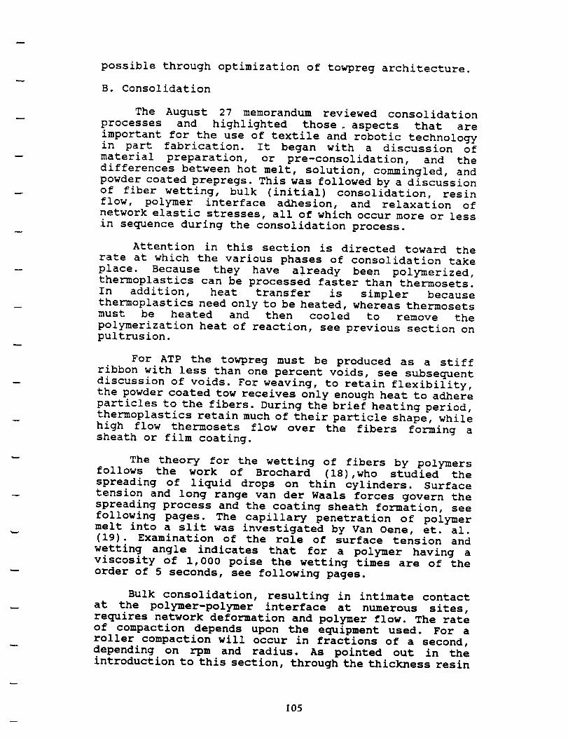
possible through optimization of towpreg architecture.
B. Consolidation
The August 27 memorandum reviewed consolidation
processes and highlighted those, aspects that are
important for the use of textile and robotic technology
in part fabrication. It began with a discussion of
material preparation, or pre-consolidation, and the
differences between hot melt, solution, commingled, and
powder coated prepregs. This was followed by a discussion
of fiber wetting, bulk (initial) consolidation, resin
flow, polymer interface adhesion, and relaxation of
network elastic stresses, all of which occur more or less
in sequence during the consolidation process.
Attention in this section is directed toward the
rate at which the various phases of consolidation take
place. Because they have already been polymerized,
thermoplastics can be processed faster than thermosets.
In addition, heat transfer is simpler because
thermoplastics need only to be heated, whereas thermosets
must be heated and then cooled to remove the
polymerization heat of reaction, see previous section on
pultrusion.
For ATP the towpreg must be produced as a stiff
ribbon with less than one percent voids, see subsequent
discussion of voids. For weaving, to retain flexibility,
the powder coated tow receives only enough heat to adhere
particles to the fibers. During the brief heating period,
thermoplastics retain much of their particle shape, while
high flow thermosets flow over the fibers forming a
sheath or film coating.
The theory for the wetting of fibers by polymers
follows the work of Brochard (18),who studied the
spreading of liquid drops on thin cylinders. Surface
tension and long range van der Waals forces govern the
spreading process and the coating sheath formation, see
following pages. The capillary penetration of polymer
melt into a slit was investigated by Van Oene, et. al.
(19). Examination of the role of surface tension and
wetting angle indicates that for a polymer having a
viscosity of 1,000 poise the wetting times are of the
order of 5 seconds, see following pages.
Bulk consolidation, resulting in intimate contact
at the polymer-polymer interface at numerous sites,
requires network deformation and polymer flow. The rate
of compaction depends upon the equipment used. For a
roller compaction will occur in fractions of a second,
depending on rpm and radius. As pointed out in the
introduction to this section, through the thickness resin
105

4
0,_._,.. +"',' , |_ %;r
OF pour QU.e_,:
Spreading of liquid drops on thin cylinders: The "manchon/droplet"transition
F. Brochard
Laboratoire de Physique de la :P[atidre Condenser. Coll_ge de France. 11 Place Marce[in-Ber_helot. 75231Paris Cedex 05. France
(Received 29 May 1985; accepted 2 January 1986)
We discuss the spreading of liquids on thin cylinders (radius b), inc'fudin g the effects of long range
attractive van der Waals (VW) forces. For volatile liquids, the vapor adsorbs on the cylinders; the
thickness e of the film is given by a balance between the disjoining V'W pressure and Laplace
pressure (e J = ba 2, where a is a molecular size). For nonvolatile liquids, a liquid drop cannot
spread out over the cylinder if the spreading coefficient S is smaller than a critical value S+. F6r
S = S_, we find a first order transition between a droplet and a sheath structure ('manchon").
ForS> S_ the droplet spreads indefinitely. The thickness of the manchon is equal to the thickness
reach_ by a drop spreading over a plane surface. We also calculate the liquid profile just below
the threshold S+. When S----.S¢, a precursor manchon appears at the two poles of the droplets.
I. INTRODUCTION
The wetting of fibers has many important industrial ap-
plications (dyeing, protection, and greasing of synthetic fi-
bers in the textile industry, hair industry, etc. ). However the
spreading of a liquid on a thin cylinder is far less understood
than the wetting on a plane surface.1. On a flat solid: A nonvolatile liquid drop spreads par-
tially until a finite contact angle 8, is established, or com-
pletely, depending upon the "spreading coeffÉcient" 5',
S:Yso --YSL --Y, (I)
where Yso and YsL are the interracial energies between solid/
air and solid/liquid and 7"is the liquid/air interracial tension.
S< 0 correspond to partial spreading. The liquid forms
a spherical cap (if gravity is negligible: small drot)let); the
contact angle O, is given by cos 0, = (Yso -- Yst. )/Y.
S > 0 corresponds to total wetting and has been analyzedin detail by .)'oanny and de Gennes. i The drop sprea(ls our
over the surface to form a "pancake.'" Contrary to common
belief the liquid does not always spread down to a mor, omo-
lecular layer. The thickness e(S) of the pancake is fixed by a
competition between S and long range forces---essential for
thin films--which tend to thicken the film. For pure V'Wforces the result is
e(S) = a .k]_--Y , (2)¥ --
where a is a molecular size. In general, y/S-,-I and e(s ) _,a.
But ifS is small, e (..V)can be relatively large. With y/S-, 102,
a-_3 ._,, one expects e(S)-_-_30/_..
2. On a thin cylinder (radius b}: The situation is quite
different. The threshold between wetting and nonwetting
cannot be exactly at S = 0. To understand this, we discuss
first two extreme limits: (a) ,5'= 0 and (b) S positive and
large.(a) The case where S -----0 exactly has been discussed by
Carroll. zJ Then a drop of large size, when put into contact
with a long fiber, does not spread out. In a flat geometry, a
film can build up because (lots = 0) the increase in liquid/
air surface energy at the outer surface (y) is balanced exactly
face. But, to cover a fiber, we need more area at the outer
surface (radius b + e, where e is the film thickness) than at
the inner surface (radius b).
In fact, the macroscopic equilibrium shape of a droplet
for this special case S = 0 has been computed; it does not
extend at infinity along the fiber. The shape is mostly spheri-
cal, with two sm_l protruding regions (of nearly zero total
curvature) in the direction of the fiber (Fig. 7).
(b) On the other hand, if,.V is large and positive, the
liquid will clearly wet the fiber; the curvature of the fiber
(which is very weak at the molecular level) cannot suppress
the wetting.
Thus in between the two regimes (a) and (b) there must
exist a critical value S t for wetting. This paper analyzes the
structure of S_ for the simple case of pure van der Waalsfluids. Most of our attention will be focused on nonvolatile
flaids, where the solid-gas interface is "dry." However, for
reference, it will be useful to discuss also the case of strongly
volatile fluids, where the vapor and the fiber are everywhere
in equilibrium; in this case we always have a liquid film on
the fiber, but the equilibrium thickness of this film will de-
pend on the fiber radius.In 5ec. II we define the appropriate free-energy rune.
tionals (free energy for the dry case, where the number of
liquid molecules is fixed, and grand chemical potential forthe wet case). In Sec. III we derive the equilibrium film
thickness e(b) for the wet case. In Sec. IV we return to the
dry case, and discuss in detail the wetting transition at
S ----S¢. Below S¢ we have a droplet and a dry fiber. Above S.
we have a manchon (sheath) covering the fiber--lx)ssibly
coexisting with a residual droplet. Section V is devoted to anumerical analysis of the shapes. The physical implicationsof the manchon structure are discussed in Sec. VI.
II.FREE ENERGY OF A lIQUID ON A CYLINDER
A. Long range forces
An essential observation, going back to Derjaguin,' is
that thin liquid films are very sensitive to long range forces.This czn be described in term of a long range energy P (per
by a gain in interracial energy at the solid (?'so -- Ys_. ) sur-10 6 unit area of film) depending upon the thickness _"of the film.
4664 J. Chem.Phys.84 (8), 15Apnl 1988 0021.98081861084664.09502.10 _) 1986 Americaninstituteof PhysiCS

r
.; [
i
46_0 :" _:3c."aed: Sorgadirg of !:CL,4d rjreos
macroscopicregime
/
//
"precursor
monchon ')
FIG. 7. Profile of a droplet on s ¢'/[{nder for S < St. Ir S--_ o a precursor
manchon appem_ on the two polm: ( l ) (5" - 5"_/S e ) =- _; ( 2 ) (5" - S,J'S, )
= _× 10-_; (3) (S -- S_/.S= ) =- _X I0-'. caicu]atexl numenc_l]y i'rom Eq.
(30) by Levinson.
_,/e_ = i --e_/a_--_y
inEx_.(34):
x, = (,_ - 1 ) e_ 22/'_'_a_ _log2 log (4.3)e_o 43 (q3+l) _'V 3r "
Ata ---- I, e, -- I0, AS/S, = ] × I0-', thenx, -- 310,_. The
size ct of the manchon diverges at S_:
a--_llog(S-S_) [, (")Y
where _"----_/a isthe scalelengthof variationof _"near
_'-----ec .
B. Droplets on a horizontal fiber
This case is more complex becausepo has to be adjusted.
We calculate now the shapes of the droplets, stable For
S<S*_, and the profiles of the manchon, stable for S>S¢*,
near the contact line where 3"_*is given by Eq. (23).
f. $ < $=: Reg/me of droplsts (Fig. 7}
For S < S _, the liquid does not wet the fiber. Macrosco-
pica@S: one observes an "unduloidal'" droplet. The shape,
largely discussed in the literature, 2e is a sphere of radius R
which matches the cylinder with a near zero surface curva.
ture (Fig. 7). The internal pressure is Po == (2v/R). The
apparent contact angle is given by the Young equadon ifS<0 and is zero ifS>O.
Microscopically: the profile at the top of the drop (_'<b)is given by
107J. Chem. Pt_cS., Vo#, 84, No. 8.15 A0rll 1988
_ zC s+ --:- = (,*5)\dx/ b 2_ 2 R y
The additional term _/R is negligible compared to the term
/b and can be omitted. The previous discussion (verticai
ascension in zero gravity ) applies; when S--*,S' _*, a "precur-
sor" manchon appears at both end of the droplet. It is shown
in Fig. 7 for three values of (S -- S_ ). At the critical value of
S (S = S_*), _he size of the manchon is from F.qs. (23) and
(38),
a----_ IogeR (46)
with e, = I00 _, _'_1/_, and a_,_ several#re.
2. S> S: ---manchons
For S>S*_, the droplets spread out on the fiber. The
profile is deduced from Eq. (29) withpo given by Eq. (26). Itleads to
a: a2 Si;-: ¢= (aT)
The profile starts with a sharp edge at x =x a
[ _'--_o(x-xo) ] and reaches the equilibrium thickness
e = #(3r)/(2s) a in a distance e=/a.
C. Remark: Cylinder of finite slze
If S> S_', the droplet spreads out over the cylinder. If
the size L r of the cylinder is smaller than the size L of the
manchon, the drop cannot spread, as explained in Sec. IV D;
we expect a drop and a film. The pressure inside the precur.
sor film has to be zero. The film thickness is then equal to e¢
whatever the value orS, provided that 5"> S ¢'. The profile is
then given by Fig. 6(c) as for a vertical cylinder in contact
with a reservoir when S>S_ in the range _'> b.
VI. CONCLUSIONS
( I)A liquiddropletspreadsover a thincylinderonlyif
the spreading coefficientS islargerthan a thresholdvalue
S_.Equivalently'foragivenpah-solid+ liquidcharacterized
by (S,y),a cylinderofradiusb can be wet by the liquidif
b > b¢,7be = a(3y/2S) 3/z.When y/S_ I,b¢ isvery small.
But ify/S,-,.,lO0,b¢,'-.,l/z.One can currentlyproduce ultra
thinfibersofradiusrangingfrom I00 to I/z.By monitoring
the spreadingofsmalldropletson fibersofdifferentsizes,it
willbe possibletotestour theoreticalpredictionsforb¢.For
S> S_,a dropletflowsout from both polestoform thestable
manchon. A simple way to display the apparitionof the
manchon istostartwith two small droplets:asthetwo man-
chons touch each other,thesmallerdropletwillflowintothe
largerdropletthrough themanchons. On theotherhand,if
,Y< S¢ the two dropletswillbe stable.
The manchon could be detected by variousmethods:
fa)electricallyusinga conducting liquidand measuringtheelectrical resistance between two electrodes attached on the
fibe_ (b) for dielectric liquids on a metallic fiber, the thick-nero • could be derived from capacitive measurements; (¢)
optically: using the available optical fibers, and observingthe changes in propagation fcatuxes induced by the film.
q: .... _. , .[_ ,-:
OF pOt_'R.,:'-"'+.:_ l.F_-v"
not
mar
let.,
the
CO Y'T-.

The Rheology of Wetting By Polymer Melts
H. VA,n OSNE. Y. F. CrL_'_c a=,_'S. NEw'xm_
Ford Motor Co., Scientific Research StaffDearborn, 3ffchigan 48121
studied, ardiverse b,:"
viscosity ar
IRt,_ivt, d November 20, 1969)
Penetration
CIassica
ABSTRACT
Theoretically, the rate of capillary, penetration of a polymer
melt into a slit, a model fo- a surface irregularity, has been shown
to defend on -/cosa/n where .y refers to the surface tension of the
liquid, n iL_ viscosity and # a time-dependent contact angle. Ana-
lytical _*xpressions reiating the depth of penetrntion with time have
been experimentally ven.qed by observations of tile penetration of
molten polyethylene and pnly-(ethylene-vinyi acetate) into alumi-
num channels. Values of n, calculated from the observed data, agree
closely with independert determinations of this material parameter.
A theoretical treatment has also been developed which describes the
velocity of spreading of a liquid drop over a flat surface. Flow
equations For the flow of free films were adapted for this purpose.The spreading velocity is predicted to depend on the product ofthree factors (1) a scaling factor, (q,/nB_), where /% is the initialradius of curvature; (2) eos@. (1-cose/cose,) where e, refers to
the equilibrium value of _, and (3) geometric terms. After demon-
strating that a drop of molten polymer may be treated as a sphericalcap, the predicted dependence of spreading rate on drop size,cos_. (nature of the subs.rate) and the sealing factor was experi-mentally verified. Some discrepancies noted at long times and hightemperatures are discussed.
INTtlODUCTION
HE FOI_MA'I"IONOf an adhesive bond between an adhesive, organic coating
or polymer melt and a surface depends on the development of a maxi-
mum area of molecular contact and the displacement of air from surface it- ,
regularities. While much attention has been given to the thermodv'namies of
wetting and adhesive forces, little quantitative work has been carried out on ' ,"the rate of approach to equilibrium conditions for viscous systems. //
Accordingly, the flow of a polymer melt over a surface under the influence
of surface tension forces has been studied by observing separately (a) the
kinetics of spreading of a drop--to obtain information about the mechanism t
of surface transport, e.g., viscous flow or surface diffusion, and (b) the rateP
of penetration into a channel or slit_a system which is a model for a sur-
face irregularity. The important factors controlling the rate of wetting were
It and _id
only is:
where O. is
the liquid: -
Since ?--_
give:
Newmav
coco dependthe remaind
designated _
parts leads t'r
Since de,
angle theref,
For e.xpein terms of t
When cosO-
The doui
criterion for
Jqp
I. ADHESION, Vol. I (January 196g), p. 54
Or:IG ,'(,-".,-i_:'#,:7-E t_
! 108 OF POOR QUALITY !,,

The Bheology of Wetting By Polymer 3fehs
pro-
applic-resort to
the latter/Ht may
if cos0 is
, (i.e. the'this is a
110%for
drop isvelocitythe/towfor the
under
(5)
(8)
into
V r
FilEure 1. Surface tensoon forces actim_ at the _erimete¢ Of a Se$SilO drOD.
Where 7s is the surface tension of the solid substrate, ° "[sL, the surface ten-
sion acting in the solid/liquid interface and y the surface tension of the liquid
in equilibrium with its vapour. At equilibrium one has, from Young'sequation:
_,cosS. + Ys_ --= _'s (9)
hence F _ 0 as cosO _ cosO..
The surface tension forces act at the perimeter of the drop. The totalforce/unit volume acting on z sessile drop of volume Vo -- '?_/3(Ro) a is there-fore:
'2,rrrF(t) 2rrr "/COS'.[ 7S-- YSL CO$O ]
Vo Vo COSS.
The maximum shear stress is therefore:
3rycosOo•t'me x
B`,3
and the velocity of spreading:
ycosO.<V> ----
,/
ycosO.
3 ryeosO.[I --cosO/cosO.] (10)
[1 -- cosO/cosO.]. _ ( 11 )
[1 -- eosO/cosO.] (r/R,,) (b/R`,) = (12)
(7)
that
(s)
It remains to find a s.uitable expression for b=, the equivalent thickness ofthe drop. When the drop shape can be approximated by that of a spherical
cap, it is possible to determine 5 directly by means of Equation (6), since_he volume of liquid ,xV that has left the domain of the original hemisphere
can be caIculated; the volumetric flow rate Q follows by differentiation of aVwith respect to time. The exact equivalent width, remains, however, still tobe determined.
' It is not nt.ce_ar_ or possible lc ql:_eif'f lhe s_irfltce tt._sio, ¢_( _he _o|id e_l_l(eilly, slnee the
exl_ eompo_itio'n of the _rubsl'rNte _urface is not k,rw'_w.. Even tho._(h _he pce_e_t experiments ire
tarried out on Aluminum plates, the _t]H'_ce Jaycr prohm_.Iy consist3 o( hydr|ted _luminum olide.
109
57
Of P('}_ QUAL!I'f

j i
H. Van Oene, Y. F. Chang arwl S. ,Vcwman
shape of a series of r%mllarty shaped objects, differing only in size, are related
to each other bv the expression: !
I
I.
;i
!
Atz "-- R2,'R_ •att P
Iwhere B, is a characteristic dimension of obiect 1. fl, that of obiect 2; ±t_
tile time required for a certain change in the shape of object I and ate, the
time required for the same change a shape for object 2. Since the whole r,'R_
vs t curve is shifted by F{_..RI, this means also that from the shape of the
r.'Ro vs t curve no specific flow mechanism can be inferred.
Even though polymer melts are very, non-Newtonian, the effect of a non-
Newtonian viscosi:v has been neglected. This is justified in view of tile small
shear rates involved. Taking (_2> _ V4h, one obtains from Eqn. (11) a
value of the max shear stress, at t -- o, of '225 dynes/era _-. For a liquid with
a viscosity of 10 _ poises, tile smallest viscosity, encountered in this work, themax.. shear rate would be only _0.2 see-'. If corrections for non-Newtonian
flow are necessary,, the equations for the flow of such a film, derived bv
Biermann [7J, should be used.
Comparing the two expressions for the spreading velocity and the rate of
penetration into a slit:
<v> --'d(r/Ro)/dt-- (w',/Ro)cos&. (1 --tosS�tosS,)[(8) (spreading)
cos8 (penetration)< v > -- dl/dt = H/6 (y/n) --T"
the question arises whether or not the time dependence of cos8 measured in
the drop spreading experiment can be used to calculate the rate of penetra-
tion. Because of the dissimilar geometries involved_penetration occurs be-
tween fixed boundaries, while in spreading there is alwavs one free boundary
_the two cos8 functions cannot be used interchangeably. Nevertheless, the
two cos O functions have a similar shape as can be derived from further anal-
ysis of the penetration data, once -//q is know,o.
Hence the assumption that cos O is some inverse function of time. which
leads to the extrapolation procedure suggested for the penetration data, isjustified.
Two explicit empirical formulae for the time dependence of cos# have ,
been suggested, the one by Newman [2J:
cos8 = cos& (1 -- ae - a ]
and the other by Kwei, Schonhorn and Frisch [8]:
cos8= kt/(1 + kt) (9.,4)
COSO.
66
llO
ORIGINAL P,_.GE IS
OF POOR QUALITY
I
E
or
In practice. :and k from
and c obtain,
perimental a
empirical.
The expo:from tile ear!
cussed their
required to a(
and L,_ a sea
drop, and in,were shifted
a mass effect.
crease in sea](
stood since E
surfaces is e,l
length, increa
vs t plots bv nsurfaces. Hen,
basis of superbe accurately
observed on e
These signi
experimental 2
pared by electhese surfaces
were prepare,0.083 M sodi,:
this surface, [
whereas on t]
minutes. Seco
traeted as de

flow requires high pressures, or long times, or both.
Resin flow depends on viscosity, pressure gradient, and
flow distance. Flow times for thermoplastic prepreg
calendering are of the order of one second (20).
Adhesion of the polymer interface by diffusion,
autohesion, is shown by Muzzy (21) to be relatively
rapid, of the order of seconds. The process begins at the
points of contact established during bulk compaction and
proceeds simultaneously with polymer flow, which provides
increased resin-resin interfacial contact.
Air flow out of gaps and voids is discussed in the
next section. As pointed out in the August 27 memorandum,
there is the potential for delamination, due to network
elasticity, if the pressu;e i_ _educed when the matrix
is still molten. To compensate for void formation due to
crystallization shrinkage, pressure should be maintained
until the composite is below Tg.
In summary, a review of the processes that occur
during consolidation indicates that time intervals of
several seconds are requires to complete the process.
Calendering utilizes pressures of the order of i00 atm
to cause through the thickness flow of polymers into thin
woven fabrics. Roller pressure intervals may be as short
as 0.01 seconds. Ultrasonic augmented pultrusion of
powder coated towpreg has been accomplished with dieresidences times a short as 0.25 seconds. Both
calendering and pultrusion utilize pressures that would
be too high for ATP applications.
Current ATP work utilizes epoxies and APC-2 towpregs
that are void free so that only tow gap consolidation
need be achieved during the roughly one second of roller
pressure. Thus, advanced composite materials for ATP also
must be preformed into similar ribbon. To speed up the
ATP process ways must be found to achieve tow gap
consolidation in fractions of a second.
C. Heat Transfer
An analysis of the ATP heat transfer processing
window was conducted by Ghasemi-Nejhad,et.al. (16). Two
important features they identifed are that the outer
surface of the towpreg cannot exceed the temperature at
which degradation occurs during the brief heating period,
and that the bottom surface of the towpreg must be above
melt temperature to achieve adhesion at the interface.
They concluded that the high heat transfer rates of
lasers are not necessary, and that hot gas or infra-red
heating is adequate to maintain the surface temperature.
Unfortunately, they stopped at this point and did not
address heating path length, melt temperature range, and
111

w
towpreg laying speed. Therefore a simple heat transfer
model was developed to identify the role of these
variables in defining the processing window.
The heat transfer process is illustrated in the
following figure. In the model, linear temperature
profiles are used to simplify calculations and to provide
guidance as to the role of properties and dimensions.
The outer surface is assumed to be subjected to a
constant temperature, To, over the heating length, L. T Ocannot exceed the resin degradation temperature for the
short exposure times. At the beginning of the heating
zone the towpreg is at temperature, Tc, and at the end of
the zone it is at (T_ + Tm)/2 , assuming a lineartemperature profile within the towpreg. To provide tackfor adhesion, the interface contact temperature must
equal or exceed Tm at L where the roller applies pressurefor consolidation. Along the interface the temperature
increases from T c to T m so that the average interface
temperature is (Tc + Tm)/2, assuming a linear rise ininterface temperature ilong the distance L.
As the heater and roller move over the surface, heatis transferred into the tow in the heated zone. The heat
acquired by the towpreg leaves with it at L.
The rate of heat conduction into the tow, while it is inthe zone is
where h is the towpreg thickness, W the towpreg band, or
heating zone, width, K the through the thickness thermal
conductivity, and Ao = WL.
The rate at which the acquired heat leaves the zone is
• " c,( _" _.--_,., T_. 2._
- L,A
where _ = Wh and U = _ the laydown rate.

113

For steady operation the energy entering the zone
equals the energy leaving, so the above equations for Q
are equal. The tow laying rate, U, is related to towpreg
properties, system dimensions, and the temperatures and
their differences by the expression
U LK[T_ - (T +____T I/__
hZ (:VCp[(To +Tm)/2 - To]
TO check the accuracy of the model the same properties
and dimensions as was used by Ghaseim-Nejhad,et.al.(16)
in their check were used. Theyr are: T O = T d = 550°C, T m
= 3400C , T c = 100OC K22 = K = 0.72 W/mOC, ¢ =
1,56o kg/m 3 , Cp = 1,425 W-sec/kg°C, h = 0.000125, and L= 2b = 0.002m
Substituting gives U = 0.040 m/sec. Interestingly, the
computer model gave U = 0.05 m/sec(16). Thus, the linear
profile model provides a conservative estimate of the
heat transfer process.
If the towpreg is heated from the bottom during
laydown the rate would be increased due to the increased
transfer area.
As indicated by the above equation, the ATP thermal
processing window dimensions are determined by three
dimensiomless quantities:
L/h which is the ratio of the heating zone length to the
towpreg thickness.
Uh C C_/K which is the ratio of the tow laying velocity,
U, to the thermal penetration velocity, K/h _ Cp.
[T O - (Tc+Tm)/2]/[(To+Tm)/2 - Tc] which is the ratio of
the average temperature difference for heat transfer to
the temperature rise of the towpreg.
The processing window boundaries are established by the
range in magnitude of these variables, see followingtable.
The ATP process window model may be used to estimate
the tape laying speed for a given system. To illustrate
this, the maximum tape laying speed, for a typical set
of resin properties and dimensions, are presented in the
following figure for a range of melt temperatures and
heater lengths. The process window is the area under the
curves. The model indicates that adequate heat transfer
can be achieved at lay down rates of 1 m/sec.
114

relationship applies for Reynolds numbers less than 2.
For higher flow rates the drag coefficient may be
introduced, however, as will be shown in the following
example, this is not necessary.
Consider a i0 micron air bubble, flowing through a
resin having a viscosity of i00 poise, under an
applied pressure gradient of I00 atm/cm.
Substituting into the above equation gives a bubble
velocity of 3.4xl04cm/sec. For a flow path of 1 cm
the time required would be 2,900 seconds or 0.8hours. The bubble Reynolds number is 104 for which
the streamline laminar flow assumption is valid.
This calculation illustrates how slowly bubbles flow
in the polymer melt. It confirms the need to avoid air
entrapment during towpreg ribbon production and in the
tow gaps during ATP. The flow obstruction technique used
by Ancher (3) as well as the use of ultrasonics by Taylor
(9) should be considered when designing dies for towpreg
ribbon production. In addition, ultrasonics might be usedwith the ATP roller to increase resin flow into the tow
gaps and thereby increase laydown speed.
ATP
correlation for high velocity compressible
through a pipe (23).
W = (_/8) ([(Pl 2 - P22}gD_]/fLRT)1/2
where W is the mass flow rate and f = Re _'a .
gas
Air flow through tow-tow channels in advance of the
roller may be estimated using the followingflow
For PI= i00 atm, P2 = 1 atm, L = 0.77 cm, D = 0.2mm, T = 200°C, and a viscosity of i00 poise,
substituting gives the weight rate of air flow to
be 0.17 g/sec. The flow conduit is 0.2 mm indiameter so that the linear air flow rate would be
3,300 m/sec, which is above the velocity of sound.
Thus, this equation does not apply. Flow at the openend of the conduit is sonic and controls the air
flow rate in the tow-tow channel.
This calculation indicates that air escapes ahead
of the roller at speeds u_ to the velocity of sound,which is 447 m/sec at 200"C. With roller speeds of 1
m/sec there will be ample time for the air in the tow gap
to exhaust. Again, the issue is one of avoiding air
entrapment in tow gaps and at the laydown interface.
U5

VI. OBSERVATIONS AND RECOMMENDATIONS
This review of various aspects of advanced tow
placement generally confirms discussions we have had in
recent weeks and provides the background for our studies
of towpreq custom ribbonizing for ATP. It also may serve
to guide work on the customizing of towpreg for braiding.
Observations
Calendering and pultrusion provide several insights
into ways to design dies and related equipment forproducting ATP towpreg ribbon.
The fact that calendering is accomplished at sheet
speeds of 2 m/sec with applied pressure intervals
of 0.01 seconds offers encouragement for possibleachievement of high speed ATP.
The flow obstruction technique used in calendering
might be modified to reduce/avoid air entrapment atthe die entrance.
The Foster-Miller experience with through the
thickness flow of LARC-TPI suggests that powder
coated towpreg may provide a better approach toachieving high speed ribbon formation.
Recent pultrusion research indicates the importance
of temperature in reducing consolidation pressure
for thermoplastics, and the value of using ultrsonicvibration of the die.
Current ATP studies are at slow laydown rates of
about 0.01 m/sec. Heat transfer may not be the rate
controlling factor in ATP on the fly consolidation.
Calculations, using a simple linear temperature profileapproach, suggest that adequate heat transfer can be
achieved at laydown rates as high as 1 m/sec. And, air
flow out of the tow gap is rapid. So. the slow ATP rates
reported bv researchers must be due _0 the slowness withwhich resin flows, and fibers move. into the tow qap_.
Ultrasonic vibration of the roller and/or the tool mightspeed the process. This observation also points to the
need to consider tows with other than rectangular crosssections.
The potential benefits of _ack on demand for ATP on
concave part surfaces should be explored. Thermoplastics
and advanced thermosets offer this advantadge. Not havingto handle tacky tow could reduce the internal tow
U6

heating/cooling problems experienced in present robot
heads. For example, when a tow is dropped, the cut hot
tow is held in a clamp. If that tow is not restarted
(unclamped and fed) within a minute or two it may gel
and require shutdown and cleaning of the robot head
mechanism.
It does not appear possible to produce ribbon on-
line during ATP. Rather than attempt to develop towpreg
dies for use on the robot, or on the floor near the
robot, it seems more reasonable to incorporate towpreg
ribbonizing with the carbon fiber production facility,
as is presently done for sizing tow. That is, powder coat
and die form (ribbonize) as the fiber tows are produced,
with subsequent delivery of spools of the ATP towpreg
ribbon to the part fabrictor for use in the ATP robot.
Recommendations
The following recommendations cover existing
research and possible future investigations. Much of what
is presented below is a rehash of things we have been
discussing in recent weeks.
During the past months, while giving top priority
to production of towpreg for weaving studies, several
attempts were made to make ATP towpreg ribbon. Both PR
500 epoxy powder towpreg yarn and LARC-TPI thermoplastic
powder towpreg yarn were passed over a hot grooved
roller. The system was similar to the re-ribbonizing
method used by Cincinnati Milcron to reduce, as received,
ribbon width variations. These trials were unsuccessful.
The primary reason that the simple ribbon groove
method did not work, even for epoxy towpreg, was the
"hairi_ess" of dry Dowde_ coated towDrea. In the coating
process, the dry tow bundle is pneumatically spread to
achieve good penetration and distribution of particles
throughout the fiber bundle. The spreading process, even
though it uses fairly gentle air flow, results in loose
and broken fibers at the towpreg surface. For weaving,
twisting the tow helped somewhat to reduce surface
"hair". Unfortunately, the simple groove die does not
adequately adhere the "hair" to the towpreg ribbon.
Two approaches are being considered to adhere the
loose surface fibers (hair) back onto the towpreg. One
idea is to pass the hot towpreg through a cone shaped
helical wire coil so that the loose fibers are wrapped
around the tow prior to its entering the ribbon die.
Another concept is to pass the hot towpreg qver two cone
rollers, one inve_t_d with reference to the other, so
117

that loose fibers on all sides of the towpreg are hot
pressed onto the tow surface before it enters the ribbondie.
The following figure illustrates the problem of tow
gads when rectangular ribbon is used for ATP. A potential
solution is to use towpreq ribbon havinq a triangular
cross section. As shown in the figure, triangular towpreg
ribbon, when laid in alternatiDq up/down sequence, has
two potential advantaqes, which should serve to increase
ATP towpreg laydown speed:
It provides tow overlap, which reqires minimum resin
flow and fiber movement during consolidation, and
It provides a large tow-tow area, which should serve
to improve adhesion and consolidation.
The shop is presently making towpreg ribbon dies
that, it is hoped, can be used to make both rectangularand triangular cross section 12 k AS 4 thermoset and
thermoplastic towpreg ribbon. The ribbon dimensions are
shown in the folowing figure. Improvements on the present
die design, if necessary, might incorporate ultrasonic
vibration to augment consolidation and the use of flow
obstruction to minmize air entrapment at the dieentrance.
Use of towpreg having a triangular cross section
will require being able to produce large quantities of
it, as well as making robot head design modifications for
its use in ATP. Once we have learned how to make
triangular cross section towpreg ribbon, two technology
transfer activities will be necessary:
Work with carbon fiber tow manufacturers to develop
on-line triangular towpeg ribbon production, and
Work with the ATP equipment manufacturers to make
appropriate design modifications in the laydownrobot head.
During our discussions we also have considered
towpreg ribbon having an ellipitical cross section. It
would offer similar advantages to triangular towpreg and
should be considered further as the dies may be simpler
or easier to operate. Round cross section towpreg does
not appear attractive since it would need to be flattened
during consolidation.
We are beginning to study tow Drea architecture for
braidina applications. If it can be made with adequate
flexibility, elliDitica_ towpreq may be attractive for
braiding. As with weaving, braiding towpreg may not need
1 18

to be consolidated into void free ribbon. It may beenough to adhere the "hair" and to smooth the surface so
that the tow-tow contact, which occurs during braiding
does not present a problem. We should begin studies of
the towpreg parameters required for braiding preformparts.
During the recent meeting with vistors from 3M
Company, the discussion of resin transfer molding, RTM,
identified micro-crack problems with tightly woven and
stitched preforms. The problem may be at the contact
points of bare fibers, which pose special resin
penetration and wetting problems during RTM. It was
observed from SEM photographs, that the high flow resins,like RP 500, form a thin, about one micron thick, sheath
(manchon), over the carbon fibers during the brief
heating period following powder deposition. If thepreform were made with this resin sheathed fiber tow
material, and if it was even stitched with it ( using a1 k towpreg yarn), there probably would not be bare fiber
contact points to serve as micro-crack orgins. A study
of towpreg architecture for resin sheathed preform
stitchina thread (yarn) may be worth pursuing.
Meanwhile work continues on improvements to the
powder coating towpreg process.

m
RECTANGULAR CROSS SECTION
• 12K TOWPREG• WIDTH RANGE
• TOW GAP RANGE
___3.0 mm It
.2m_-_
3.4 mm
IT
0.2 mmAq
0.0 mm 0.20 mm 0.40 mm
TRIANGULAR CROSS SECTION
• 12K TOWPREG• WIDTH RANGE
• TOW GAP RANGE
0.0 mm 0.20 mm 0.40 mm
• TOW OVERLAP RANGE
1.2 mm
1.4 mm
0.4 mm
0.4 mm
0.4 mm
0.2 mm
TOW PLACEMENT ARCHITECTURE
1Z0

References
i. R.E. Gaskel, "The Calendering of Plastic Materials",
J.Appl. Mech., Vol 17 pp334-336 (1950).
2. F.H. Ancher, "Calendering of Laminated Polymeric
Materials", U.S. Patent No. 3,849,174, Nov. 19 (1974).
3. F.H. Ancher, "Calendering of Polymeric Materials",
U.S. Patent No. 3,658,978, July 7,(1969).
4. A.A. Tseng, "Layflat Behavior and Temperature
Variation in Calendering: A Review", J. Thermoplastic
Composite Materials, Vol 4 pp123-139 (1991).
5. Foster-Miller,Inc. Progress Report, NASA Contract No.
NAS 1-19095, July 22 (1991).
6. J.W. Seo and W.I. Lee, "A Model of the Resin
Impregnation in Thermoplastic Composite," J.Composite
Materials, Vol 25 ppi127-i142 (1991).
7. W.I. Lee and G.S. Springer, "Pultrusion of
Thermoplastics," 36th International SAMPE Symposium
Transactions, pp1309-1317, April (1991).
8. B.T. Astrom, P.H. Larsson and R.B. Pipes,
"Experimental Investigation of a Thermoplastic Pultrusion
process", 36th International SAMPE Symposium
Transactions, pp1319-1331, April (1991).
9. S.R. Taylor and W.M. Thomas, "High Speed Pultrusion
of Thermoplastic Composites", 22nd International SAMPE
Technical Conference Thransactions, pp78-87, November
(1990) .
i0. G.L. Batch, "Crosslinking Free Radical Kinetics and
the Pultrusion Processing of Composites", PhD Thesis,
University of Minnesota (D.C. Macosko advisor) (1989).
ii. Y.R. Kim, S.P. McCarthy and J.P.Fanucci,
"Compressibility and Relaxation of Fiber Reinforcements
During Composite Processing", Polymer Composites, Vol 12,
No i, pp13-19 (1991).
12. J.P. Fanucci, S.C. Nolet, C. Koopernoes, and Y.R.
Kim, "Measurement of Internal Die Pressure Distribution
During Pultrusion of Thermoplastic Composite", 22nd
International SAMPE Technical Conference Transactions,
pp50-64, November (1990).
121

13. R.L. Anderson and C.G. Grant, "Advanced Fiber
Placement of Composite Fuselage Structures", First NASA
Advanced Composites Technology Conference, NASA
Conference Publication 3104, Part 2, pp817-830 (1991).
14. D.O. Evans, M.M. Vaniglia and P.C. Hopkins, "Fiber
Placement Process Study", 34th International SAMPE
Symposium Transactions, pp1822-1833, (1989).
15. M.L. Enders and P.C. Hopkins, "Developments in the
Fiber Placement process", 36th International SAMPE
Symposium Transactions, pp778-790, April (1991).
16. M.N. Ghasemi-Nejhad, R.D. Cope and S.I. Guceri,
"Thermal Analysis of in-situ Thermoplastic Composite Tape
Laying", J. Thermoplastic Composite Materials, Vol 4,
pp20-45, January (1991).
17. G. Ardichvili, "An Attempt at a Rational
Determination of the Ambering of Calender Rolls",
Kautschuk, Vol 14, pp23-28, (1938).
18. F. Brochard, "Spreading of Liquid Drops on Thin
Cylinders: the 'Manchon/Droplet' Transition", J. Chem.
Phys., Vol 84 no 8 pp 4664-4472 (1986).
19. H, Van Oene, Y.F. Chang and S. Newman, "The Rheology
of Wetting by Polymer Melts", J. Adhesion, Vol i, pp54-68 (1969).
20. S.S. Bafna and D.G. Baird,"Impregnation in
Thermoplastic Prepregs: Model & Experiments", 36th
International SAMPE Symposium Transactions,ppl708"1719,
April (1991).
21. J.D. Muzzy,"Processing of Advanced Thermoplastic
Composite", ASME Manufacturing International '88
Proceedings, Vol IV, The Manufacturina Scienc_ of
ComDosit_, T.G. Gutowski, editor, pp27-39 (1989).
22. K.J. Ahn, J.C. Serferis, J.O. Price and A.J. Berg,
"Permeation Measurements Through Prepreg Laminates",
SAMPE Journal, Vol 27, No 6, pp19-26 (1991).
23. J.H. Perry, ed., Chemical Enaineer's Handbook, 4th
Edition, p 5-24, McGraw-Hill (1963).
122