Department of Biochemical- and Chemical Engineering Chair of Mechanical Process Engineering 1...
107
Department of Biochemical- and Chemical Engineering Chair of Mechanical Process Engineering 1 Planning and Design of a Process for PGM Ore Dressing
-
Upload
felicia-mccarthy -
Category
Documents
-
view
217 -
download
3
Transcript of Department of Biochemical- and Chemical Engineering Chair of Mechanical Process Engineering 1...
Department of Biochemical- and Chemical Engineering
Chair of Mechanical Process Engineering
1
Planning and Design of a Process for PGM Ore Dressing

Department of Biochemical- and Chemical Engineering
Chair of Mechanical Process Engineering
2
Presentation topics Presented by
Introduction A.Chandan
Process Units
• Size reduction Ramakrishna
• Froth flotation Padala
• Pyrometallurgy Tariq
• Hydrometallurgy Kumar
Water Treatment Selva
Plant Layout B.Ravikumar
Environmental Regulation and Safety Yozi Bastian
Cost Estimation Amar
Planning and Design of a Process for PGM ore Dressing

Department of Biochemical- and Chemical Engineering
Chair of Mechanical Process Engineering
3
TASKTASK
Planning and Design of a Process for PGM ore Dressing
PGM Ore
PROCESS
Merensky-Reef
600 t/h
PGM
Concentrate
PGMs
50-90 %
PGMs
5.5 g/t

Department of Biochemical- and Chemical Engineering
Chair of Mechanical Process Engineering
4
Material %Sand 95
Metal Oxides 2Minerals 3
Planning and Design of a Process for PGM ore Dressing
Mineral %Pyrrhotie(Fe1-xS) 75,61
Pentlandite(Fe,Ni)9S8 12,66Chalcopyrite(CuFeS2) 7,69
Pyrite(FeS2) 4Braggite((Pd,Pt,Ni)S) 0,0073PlatinumSulfide(PtS) 0,0073
Palladium Sulfide(PdS) 0,0044Laurite(RuS2) 0,0024
Erlichmanite(OsS2) 0,0002Irridium disulphide(IrS2) 0,00024
Auricupride(Cu3Au) 0,0012Rhodium Disulfide(RhS2) 0,00089

Department of Biochemical- and Chemical Engineering
Chair of Mechanical Process Engineering
5
PFD3D-layout
Individual unit layout
PGMsApplications
Process block diagram
Fixed capital investmentsWorking capital (p.a)
Breakeven point
Individual process selectionProcess description
Process block diagram
TOPICS
INTRODUCTION
INDIVIDUAL UNITS
PLANT LAYOUT
COST
CONCLUSION
Planning and Design of a Process for PGM ore Dressing
Department of Biochemical- and Chemical Engineering
Chair of Mechanical Process Engineering
6
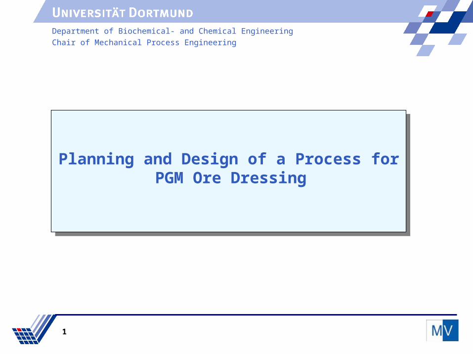
PERIODIC TABLE
Platinum Group Metals
1. Pt Platinum
2. Pd Palladium
3. Rh Rhodium
4. Ir Iridium
5. Ru Ruthenium
6. Os Osmium
Platinum Group Metals
1. Pt Platinum
2. Pd Palladium
3. Rh Rhodium
4. Ir Iridium
5. Ru Ruthenium
6. Os Osmium
INTRODUCTION
By: A.CHANDAN
Planning and Design of a Process for PGM ore Dressing

Department of Biochemical- and Chemical Engineering
Chair of Mechanical Process Engineering
7
Platinum coated computer hard drive disks.Platinum-based drugs can be used to treat a number of cancers.
Rhodium foils are used in equipment for detecting cancer.
Palladium salts are used in electroplating and in the manufacture of process catalysts.
Platinum jewellery
APPLICATIONS
PGM Ore
Planning and Design of a Process for PGM ore Dressing
Department of Biochemical- and Chemical Engineering
Chair of Mechanical Process Engineering
8
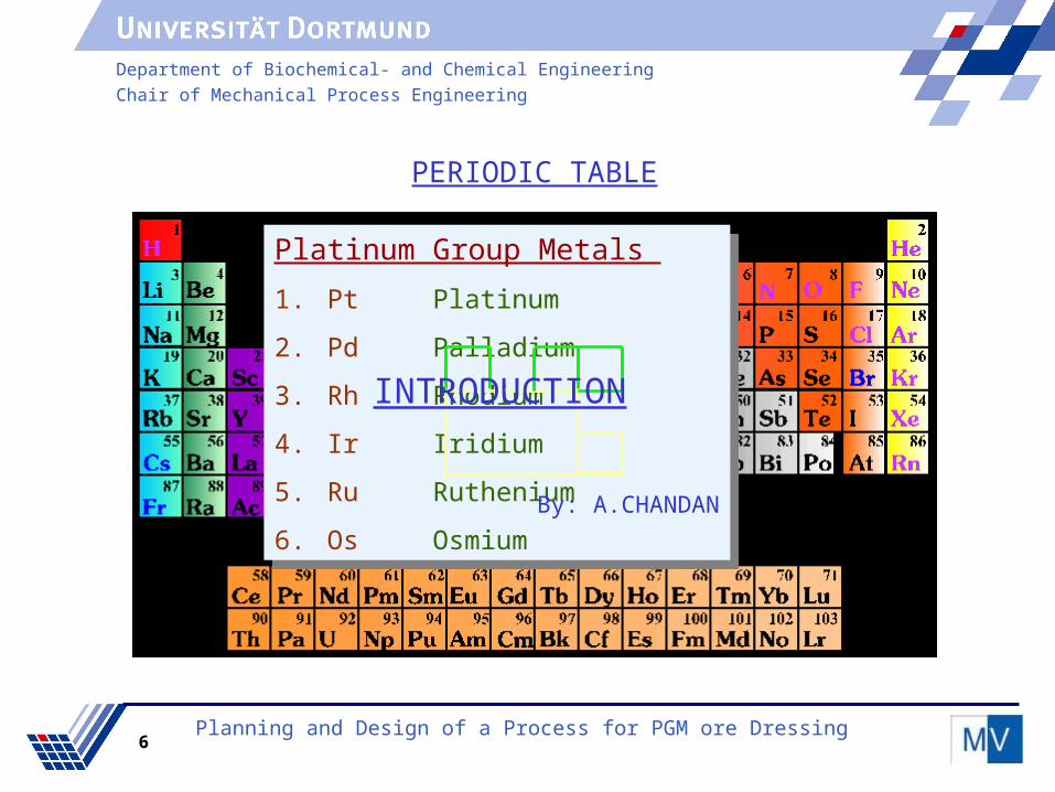
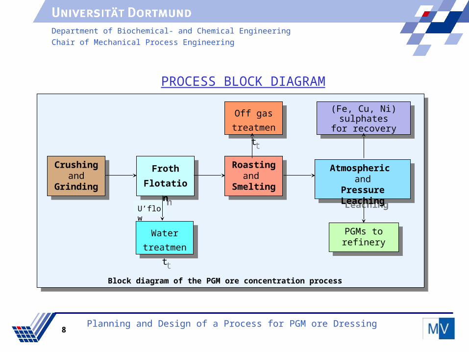
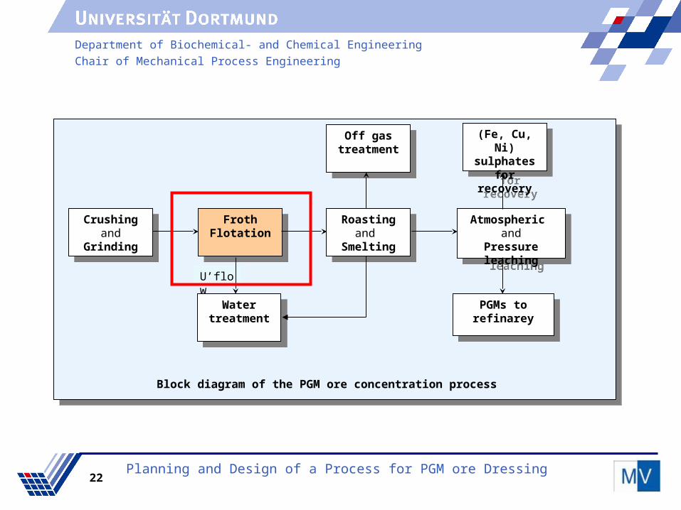
PROCESS BLOCK DIAGRAMPROCESS BLOCK DIAGRAM
PROCESS BLOCK DIAGRAM
Froth
Flotation
Froth
Flotation
Crushingand
Grinding
Crushingand
Grinding
Roastingand
Smelting
Roastingand
Smelting
Water
treatment
Water
treatment
Off gas
treatment
Off gas
treatment
Atmospheric and
Pressure Leaching
Atmospheric and
Pressure Leaching
(Fe, Cu, Ni) sulphates
for recovery
(Fe, Cu, Ni) sulphates
for recovery
PGMs to refinery
PGMs to refinery
U’flow
Block diagram of the PGM ore concentration process
Planning and Design of a Process for PGM ore Dressing

Department of Biochemical- and Chemical Engineering
Chair of Mechanical Process Engineering
9
Size Reduction
By
Ramakrishna
Planning and Design of a Process for PGM ore Dressing

Department of Biochemical- and Chemical Engineering
Chair of Mechanical Process Engineering
10Planning and Design of a Process for PGM ore Dressing
FrothFlotation
FrothFlotation
Crushingand
Grinding
Crushingand
Grinding
Roastingand
Smelting
Roastingand
Smelting
Water treatment
Water treatment
Off gas treatment
Off gas treatment
Atmospheric and
Pressure leaching
Atmospheric and
Pressure leaching
(Fe, Cu, Ni) sulphates
for recovery
(Fe, Cu, Ni) sulphates
for recovery
PGMs to refinarey
PGMs to refinarey
U’flow
Block diagram of the PGM ore concentration process
Department of Biochemical- and Chemical Engineering
Chair of Mechanical Process Engineering
11
Contents
Process Options and Selection
Equipment Selection
Crushing
Grinding
Solid-Liquid Separator
Process Flow Diagram
Design Parameters
Process Options and Selection
Equipment Selection
Crushing
Grinding
Solid-Liquid Separator
Process Flow Diagram
Design Parameters
Planning and Design of a Process for PGM ore Dressing
Department of Biochemical- and Chemical Engineering
Chair of Mechanical Process Engineering
12
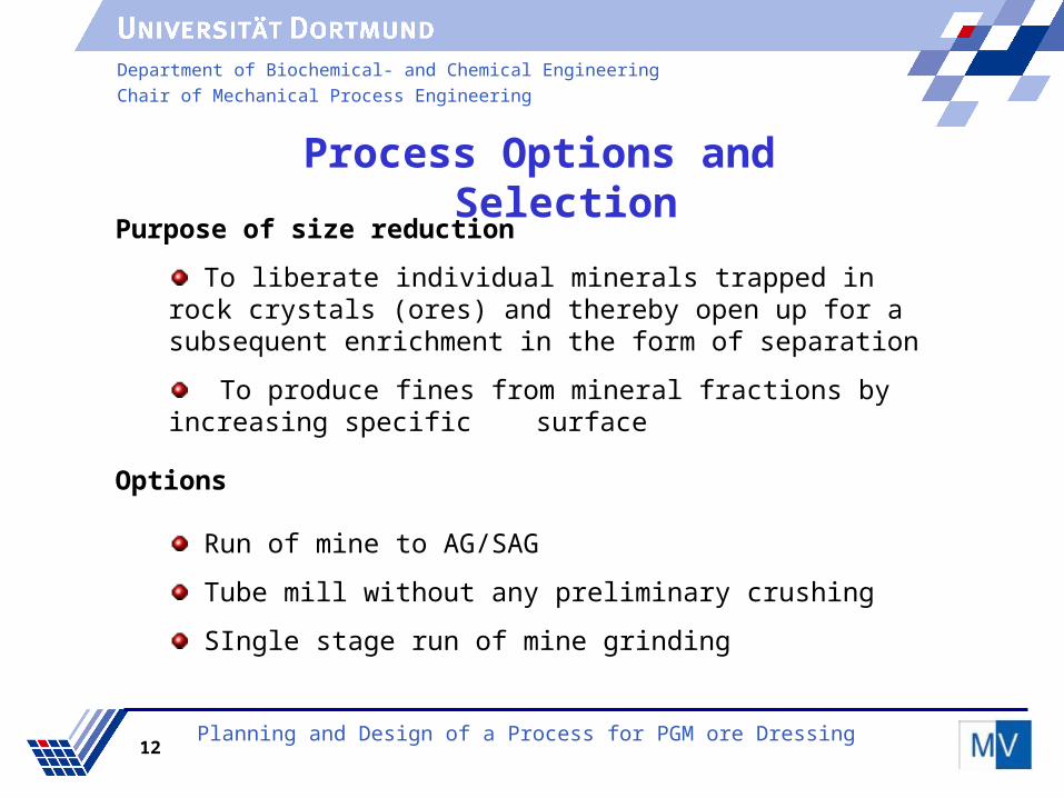
Process Options and Selection
Run of mine to AG/SAG
Tube mill without any preliminary crushing
SIngle stage run of mine grinding
Options
Planning and Design of a Process for PGM ore Dressing
Purpose of size reduction
To liberate individual minerals trapped in rock crystals (ores) and thereby open up for a subsequent enrichment in the form of separation
To produce fines from mineral fractions by increasing specific surface

Department of Biochemical- and Chemical Engineering
Chair of Mechanical Process Engineering
13
Process Steps
Selection Parameters
Particle size
Reduction ratio
Power requirement
Hardness of the ore
Selection Parameters
Particle size
Reduction ratio
Power requirement
Hardness of the ore
Process steps
Stationary Screening
Primary Crushing
Secondary Crushing
Tertiary Crushing
Screening
Grinding (wet grinding)
Solid-Liquid Seperation
Process steps
Stationary Screening
Primary Crushing
Secondary Crushing
Tertiary Crushing
Screening
Grinding (wet grinding)
Solid-Liquid Seperation
Planning and Design of a Process for PGM ore Dressing
Department of Biochemical- and Chemical Engineering
Chair of Mechanical Process Engineering
14
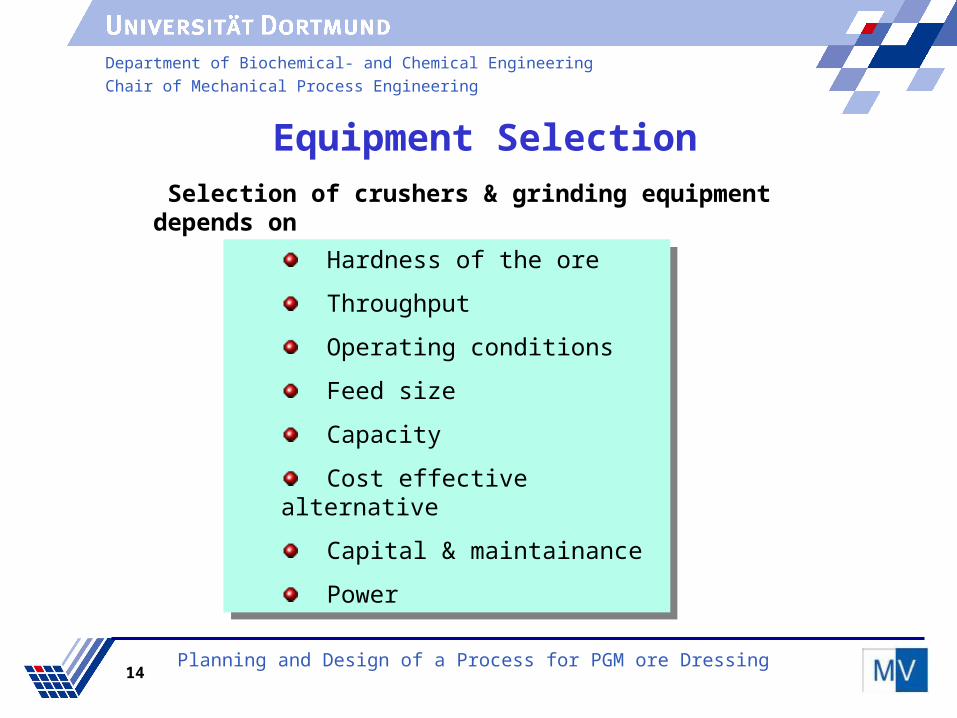
Equipment Selection Selection of crushers & grinding equipment depends on
Hardness of the ore
Throughput
Operating conditions
Feed size
Capacity
Cost effective alternative
Capital & maintainance
Power
Hardness of the ore
Throughput
Operating conditions
Feed size
Capacity
Cost effective alternative
Capital & maintainance
Power
Planning and Design of a Process for PGM ore Dressing

Department of Biochemical- and Chemical Engineering
Chair of Mechanical Process Engineering
15
Selection of Crushers
Roll, hammer, Impact crushers are suitable for soft ore and for low capacities
For harder feed there is a choice between a gyratory and a jaw crusher
Compared to other crushers the cone crusher has some advantages
Making them very suitable for size reduction and shaping downstream a crushing circuit.
Possibilities to change feed and discharge openings during operation
Equipment Selection
Cone crusherTertiary crusher
Cone crusherSecondary crusher
Jaw crusherPrimary crusher
Crusher typeCrushing stage
Planning and Design of a Process for PGM ore Dressing

Department of Biochemical- and Chemical Engineering
Chair of Mechanical Process Engineering
16
Equipment SelectionSelection of Grinding Equipment
Planning and Design of a Process for PGM ore Dressing
Rod mills usually run open circuit
The selection is in between AG/SAG and ball mill.
Advantages of Ball mill
It can be used for wet or dry, wet grinding facilitates the removal of the product
Installation and power costs are low and the grinding medium is cheap and suitable for hard materials
It can be used for batch or continuous operation and also in open or closed circuit grinding

Department of Biochemical- and Chemical Engineering
Chair of Mechanical Process Engineering
17
Equipment Selection
Planning and Design of a Process for PGM ore Dressing
Advantages of hydrocyclones over centrifuges
Simple construction & cheaper than centrifuge Low maintenance Less space required Control of speed is easier Low energy consumption Higher efficiency with low cost can be obtained Higher capacity can be handled by operating multiple
hydrocyclones (hydrocyclone battery)
Selection of Solid-Liquid seperator

Department of Biochemical- and Chemical Engineering
Chair of Mechanical Process Engineering
18
Process Flow Diagram
Planning and Design of a Process for PGM ore Dressing

Department of Biochemical- and Chemical Engineering
Chair of Mechanical Process Engineering
19
Design Results
Planning and Design of a Process for PGM ore Dressing
Crushers Results
Crushing stage
Crusher type Particle size (mm) Power (kW)
Inlet Outlet
Primary crusher
Jaw crusher 400 134 364
Secondary crusher
Cone crusher 134 32 597
Tertiary crusher
Cone crusher (2)
32 9 373

Department of Biochemical- and Chemical Engineering
Chair of Mechanical Process Engineering
20
Results
Planning and Design of a Process for PGM ore Dressing
Hydrocyclone
Number of hydrocyclones = 11
Cone angle = 20°
D50C = 92.5µ
Ball mill
7.0MWPower required
17.64rpmNc
11.47rpmN
0.65N/Nc
5.74 mD
11.48 mL
2L/d Ratio

Department of Biochemical- and Chemical Engineering
Chair of Mechanical Process Engineering
21
Froth Flotation
by
Padala Subrahmanyeswara Reddy
Department of Biochemical- and Chemical Engineering
Chair of Mechanical Process Engineering
22Planning and Design of a Process for PGM ore Dressing
FrothFlotation
FrothFlotation
Crushingand
Grinding
Crushingand
Grinding
Roastingand
Smelting
Roastingand
Smelting
Water treatment
Water treatment
Off gas treatment
Off gas treatment
Atmospheric and
Pressure leaching
Atmospheric and
Pressure leaching
(Fe, Cu, Ni) sulphates
for recovery
(Fe, Cu, Ni) sulphates
for recovery
PGMs to refinarey
PGMs to refinarey
U’flow
Block diagram of the PGM ore concentration process

Department of Biochemical- and Chemical Engineering
Chair of Mechanical Process Engineering
23
Froth Flotation
Process Selection
Purpose
Flotation Reagents And Amounts
Flotation Machines - Selection
Flotation Circuit
Flotation Process Flow Sheet
Results
Planning and Design of a Process for PGM ore Dressing

Department of Biochemical- and Chemical Engineering
Chair of Mechanical Process Engineering
24
Processes
Gravity Separation or Flotation
Selection
Froth Flotation
Purpose
Minerals – 3%
Metal Oxides – 2%
Gangue(Sand) – 95%
Concentrating minerals
Froth Flotation
Planning and Design of a Process for PGM ore Dressing

Department of Biochemical- and Chemical Engineering
Chair of Mechanical Process Engineering
25
Froth Flotation
Flotation Reagents And Amounts
Reagent Name Amount
Collector Sodium Ethyl Xanthate
1 kg/ton of feed
Frother Pine Oil 1 kg/ton of feed
Activator Copper Sulfate 1kg/ton of feed
Planning and Design of a Process for PGM ore Dressing

Department of Biochemical- and Chemical Engineering
Chair of Mechanical Process Engineering
26
Froth Flotation
Flotation Machines
Outokumpu Flotation Machines
Basic Inventory is 20% lower than in a conventional plant
Low space requirements
A simple design with low maintenance cost
Low power requirements
Easy performance control
Fast froth removal
Planning and Design of a Process for PGM ore Dressing

Department of Biochemical- and Chemical Engineering
Chair of Mechanical Process Engineering
27
Froth FlotationFlotation Circuit
Planning and Design of a Process for PGM ore Dressing
Department of Biochemical- and Chemical Engineering
Chair of Mechanical Process Engineering
28
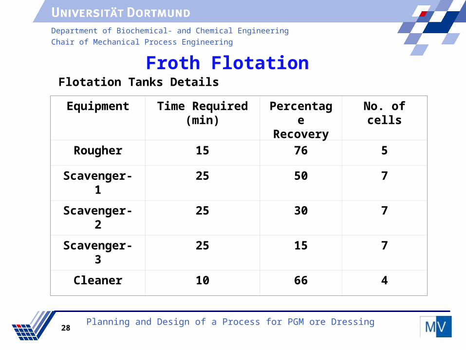
Froth FlotationFlotation Tanks Details
Equipment Time Required (min)
Percentage
Recovery
No. of cells
Rougher 15 76 5
Scavenger-1
25 50 7
Scavenger-2
25 30 7
Scavenger-3
25 15 7
Cleaner 10 66 4
Planning and Design of a Process for PGM ore Dressing

Department of Biochemical- and Chemical Engineering
Chair of Mechanical Process Engineering
29
Froth FlotationProcess Flow Sheet
Planning and Design of a Process for PGM ore Dressing

Department of Biochemical- and Chemical Engineering
Chair of Mechanical Process Engineering
30
Froth Flotation
Results
PGMs in feed = 3.28 kg/hr
PGMs in Concentrate = 2.94 kg/hr
PGMs in Tailings = 0.34 kg/hr
Percentage of Extraction = 89.5
Percentage Purity = 90
Planning and Design of a Process for PGM ore Dressing
Department of Biochemical- and Chemical Engineering
Chair of Mechanical Process Engineering
31
Pyrometallurgy
By
Tariq Anwar

Department of Biochemical- and Chemical Engineering
Chair of Mechanical Process Engineering
32Planning and Design of a Process for PGM ore Dressing
FrothFlotation
FrothFlotation
Crushingand
Grinding
Crushingand
Grinding
Roastingand
Smelting
Roastingand
Smelting
Waste water treatment
Waste water treatment
Off gas treatment
Off gas treatment
Atmospheric and
Pressure leaching
Atmospheric and
Pressure leaching
(Fe, Cu, Ni) sulphates
for recovery
(Fe, Cu, Ni) sulphates
for recovery
PGMs to refinarey
PGMs to refinarey
U’flow
Block diagram of the PGM ore concentration process

Department of Biochemical- and Chemical Engineering
Chair of Mechanical Process Engineering
3333
Contents
Roasting
Smelting
Atomization
Process flow diagram
Results
Pyrometallurgy
Planning and Design of a Process for PGM ore Dressing
Department of Biochemical- and Chemical Engineering
Chair of Mechanical Process Engineering
34
Roasting
Converts sulphides to oxides or sulphates
Why ?
Ore is rich in sulphides
Eliminates fugitive SO2 emissions from smelter
Produces SO2 of high concentration for Sulphuric acid production
Reduced energy consumption for smelting
Roasting eliminates drying
Roasting
Planning and Design of a Process for PGM ore Dressing

Department of Biochemical- and Chemical Engineering
Chair of Mechanical Process Engineering
35
Reactions
2FeS2 + 11 O2 Fe2O3 + 4SO2
2FeS + 3O2 2FeO + 2SO2
2CuFeS2 + 13/2O2 2CuO + 4SO2 + Fe2O3
Feed size ~ 74 microns Operating temperature & pressure ~ 1000 °C & 1bar
Considerations
Involves gas-solid reactions
Reactions begin at the outer layer of the solid particle
Outer layers are converted into new compounds
“Ash layer” diffusion controls reaction
Roasting
)/(41 molkcal)/(3.22 molkcal)/(2.44 molkcal
Planning and Design of a Process for PGM ore Dressing

Department of Biochemical- and Chemical Engineering
Chair of Mechanical Process Engineering
36
Options
Multiple hearth roaster
Fluidized bed roaster
Fluidized bed advantages
Easy handling and transport of solids
Large throughput possible
Uniform temperature distribution
Large solid gas exchange area
Suitable for handling smaller particles
Roasting
Planning and Design of a Process for PGM ore Dressing
Department of Biochemical- and Chemical Engineering
Chair of Mechanical Process Engineering
37
Reduction with carbon, forming, two layers – metallic layer & slag layer
Reductant & fluxes are added to reduce metal oxides to metals
Why ?
PGM‘s are conveniently “collected” in iron based alloy
PGM losses are very low
Base metals of high purity are formed
High reaction rates
Well established process
Smelting
Planning and Design of a Process for PGM ore Dressing

Department of Biochemical- and Chemical Engineering
Chair of Mechanical Process Engineering
38
Options
A.C. (alternating current) arc furnace
D.C. (direct current) plasma arc furnace
D.C. Plasma arc furnace advantages
Can handle fines
Dc arc is more stable than ac arc
Simple construction (single electrode) - easy gas sealing
Very high temperatures can be attained
Little off gas volume - less losses
Can process chromite bearing PGM ore(UG2 ore)
Planning and Design of a Process for PGM ore Dressing
Smelting

Department of Biochemical- and Chemical Engineering
Chair of Mechanical Process Engineering
39
Temperatures
Off gases ~ 1100 °C
Metal & slag ~ 1600 °C
Plasma column ~ 20000 °C
Arc attachment zone ~ 2500°CRoof & walls are water cooled !
Reactions
FeO + C Fe + CO
NiO + C Ni + CO
CuO + C Cu + CO
Fe2O3 + C 2Fe + 3CO
Planning and Design of a Process for PGM ore Dressing
Smelting

Department of Biochemical- and Chemical Engineering
Chair of Mechanical Process Engineering
40
Convert the hot molten metal coming from DC arc furnace into solid particles
of appropriate size for subsequent leaching step
Options
Water atomizer
Gas atomizer
Water atomizer advantages
Widely used for powders of Au, Pd, Pt, Co, Cu, Ni, & Fe
Particle size from 10 microns to few millimeters
The particles are irregular in shape
Cost effective as compared to granulation & milling
Atomization
Planning and Design of a Process for PGM ore Dressing

Department of Biochemical- and Chemical Engineering
Chair of Mechanical Process Engineering
41
Process flow diagram
Planning and Design of a Process for PGM ore Dressing

Department of Biochemical- and Chemical Engineering
Chair of Mechanical Process Engineering
42
Results
Planning and Design of a Process for PGM ore Dressing
Roaster
Height ~ 12.6 m
Diameter ~ 8.2 m
Fluidization velocity ~ 0.8 m/s
Smelter
Power consumption ~ 15.2 MW
Operating current ~ 33.6 kA
Electrode diameter ~ 473 mm
Capacity ~ 45 tonnes

Department of Biochemical- and Chemical Engineering
Chair of Mechanical Process Engineering
43
Results
Planning and Design of a Process for PGM ore Dressing
Atomizer
Height ~ 3 m
Diameter ~ 1.2 m
Water flow rate ~ 16.6 Kg/s
Product size ~ 14 microns
Roastingand
Smelting
Roastingand
Smelting
0.016 % PGM’s 0.03 % PGM’s

Department of Biochemical- and Chemical Engineering
Chair of Mechanical Process Engineering
44
Hydrometallurgy
by
Kumar
Planning and Design of a Process for PGM ore Dressing

Department of Biochemical- and Chemical Engineering
Chair of Mechanical Process Engineering
45Planning and Design of a Process for PGM ore Dressing
FrothFlotation
FrothFlotation
Crushingand
Grinding
Crushingand
Grinding
Roastingand
Smelting
Roastingand
Smelting
Waste water treatment
Waste water treatment
Off gas treatment
Off gas treatment
Atmospheric and
Pressure leaching
Atmospheric and
Pressure leaching
(Fe, Cu, Ni) sulphates
for recovery
(Fe, Cu, Ni) sulphates
for recovery
PGMs to refinarey
PGMs to refinarey
U’flow
Block diagram of the PGM ore concentration process

Department of Biochemical- and Chemical Engineering
Chair of Mechanical Process Engineering
46
ContentsLeaching
Process classification
Selection of process
Block diagram
Considerations
Reactions
Equipment selection
Process flow diagram
Design parameters
Planning and Design of a Process for PGM ore Dressing

Department of Biochemical- and Chemical Engineering
Chair of Mechanical Process Engineering
47
Leaching
Two main steps are involved is
Contact of liquid solvent with the solid to effect transfer of solute from the solid to the solvent.
Separation of resulting solution from the residual solid.
Planning and Design of a Process for PGM ore Dressing

Department of Biochemical- and Chemical Engineering
Chair of Mechanical Process Engineering
48
Process Classification
Insoluble PGM residue
The base metal is dissolved leaving the PGMs in a highly concentrated residue suitable for refining
Dissolved PGM
The base metal and PGMs are dissolved together, and then subsequent separation of each metals in a sequence of hydrometallurgical operations
Planning and Design of a Process for PGM ore Dressing

Department of Biochemical- and Chemical Engineering
Chair of Mechanical Process Engineering
49
Selection of processAtmospheric leach
simpler to operate
cheaper
most reliable to leach the bulk
Pressure leach
To speed the dissolution of all values into the leach solution
improve the solubility rate of solids that are at best only slowly soluble at atmospheric leach.
Atmospheric leach - Iron and Nickel
Pressure oxidative leach - Copper
Planning and Design of a Process for PGM ore Dressing

Department of Biochemical- and Chemical Engineering
Chair of Mechanical Process Engineering
50
Considerations
Physical characterstics of the solids
Process and operating conditions
Choice of solvent
Temperature
Leaching cycle and contact method
Type of reactor
Planning and Design of a Process for PGM ore Dressing

Department of Biochemical- and Chemical Engineering
Chair of Mechanical Process Engineering
51
Block diagram
Planning and Design of a Process for PGM ore Dressing
Atmospheric Leaching
60°C & 1atm
Liquid/Solidseparator
PressureLeaching
110°C & 7 bar
Liquid/Solidseparator
Liquid by-product
Solid product
14 µm from
atmoizer
Department of Biochemical- and Chemical Engineering
Chair of Mechanical Process Engineering
52
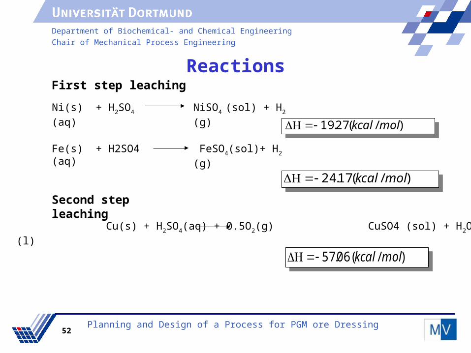
First step leaching
Ni(s) + H2SO4 (aq) NiSO4 (sol) + H2 (g)
)/(27.19 molkcal
Fe(s) + H2SO4 (aq) FeSO4(sol)+ H2 (g)
)/(17.24 molkcal
)/( 06.57 molkcal
Second step leaching
Planning and Design of a Process for PGM ore Dressing
Cu(s) + H2SO4(aq) + 0.5O2(g) CuSO4 (sol) + H2O (l)
Reactions

Department of Biochemical- and Chemical Engineering
Chair of Mechanical Process Engineering
53
Equipment Selection
Selection Basis
Good solid-liquid mixing
High conversion
Easy to install and control
Atmospheric leach
Continous stirred tank reactor
Pressure leach
Autoclave reactor
Planning and Design of a Process for PGM ore Dressing

Department of Biochemical- and Chemical Engineering
Chair of Mechanical Process Engineering
54
Process flow diagram
Planning and Design of a Process for PGM ore Dressing

Department of Biochemical- and Chemical Engineering
Chair of Mechanical Process Engineering
55
Design parameters
Parameter C.S.T.R Autoclave
Residence time (hours)
5.15 5
Volume (m3) 40 5
L/D 1 5
Diameter (m) 3.7 5
Length (m) 3.7 1
Planning and Design of a Process for PGM ore Dressing
Department of Biochemical- and Chemical Engineering
Chair of Mechanical Process Engineering
56
Water treatment
By
Selva kumar
Planning and Design of a Process for PGM ore Dressing

Department of Biochemical- and Chemical Engineering
Chair of Mechanical Process Engineering
57Planning and Design of a Process for PGM ore Dressing
FrothFlotation
FrothFlotation
Crushingand
Grinding
Crushingand
Grinding
Roastingand
Smelting
Roastingand
Smelting
Water treatment
Water treatment
Off gas treatment
Off gas treatment
Atmospheric and
Pressure leaching
Atmospheric and
Pressure leaching
(Fe, Cu, Ni) sulphates
for recovery
(Fe, Cu, Ni) sulphates
for recovery
PGMs to refinarey
PGMs to refinarey
U’flow
Block diagram of the PGM ore concentration process

Department of Biochemical- and Chemical Engineering
Chair of Mechanical Process Engineering
58
Contents
Planning and Design of a Process for PGM ore Dressing
Process selection
Block diagram
Screening
Sedimentation
Ion exchange
Process Flow Diagram

Department of Biochemical- and Chemical Engineering
Chair of Mechanical Process Engineering
59
Water Treatment
Purpose of water treatment
Water conservation
reuse water
control water pollution
Purification of water
Planning and Design of a Process for PGM ore Dressing

Department of Biochemical- and Chemical Engineering
Chair of Mechanical Process Engineering
60
Preliminary treatment includes screening, comminution, grit
removal, oil and grease removal etc.
Primary treatment includes gravity separation, flotation, filtration,
thickener etc
Secondary treatment includes ion exchange, reverse osmosis,
adsorption etc
Tertiary treatment includes biological treatment, chemical treatment
Planning and Design of a Process for PGM ore Dressing
Process selection

Department of Biochemical- and Chemical Engineering
Chair of Mechanical Process Engineering
61
Block diagram
Planning and Design of a Process for PGM ore Dressing

Department of Biochemical- and Chemical Engineering
Chair of Mechanical Process Engineering
62
Chair of Mechanical Process Engineering
Screening
Sedimentation
Solid-liquid separation - utilizes gravity (size and specific weight) to
remove suspended solid
Here most of gangue materials from froth tailings are removed
Sedimentation Processes - Thickening and clarification
Removing the floatable solids
Vibration screen is preferred, because
It can handle high capacity per unit area
increased accuracy of sizing & low maintenance cost
Planning and Design of a Process for PGM ore Dressing

Department of Biochemical- and Chemical Engineering
Chair of Mechanical Process Engineering
63
Chair of Mechanical Process Engineering
Clarification Process to remove relative amount of fine suspended particles and
produce clear effluent
For better separation of colloidal particles by gravity, it is necessary to
agglomerate them by addition of coagulants and flocculants.
Coagulants and flocculants
Coagulants- destabilization of colloidal suspension
Flocculants- agglomeration of the neutralized colloids
Planning and Design of a Process for PGM ore Dressing

Department of Biochemical- and Chemical Engineering
Chair of Mechanical Process Engineering
64
Inorganic coagulants
increases coagulation
But modifies the physical-chemical characteristic of the water
(conductivity, pH) and increases sludge volume.
Organic Coagulant
Polyelectrolyte is used because it reduces sludge volume and does not alter pH.
Sedimentation Unit
Tank, Drive unit, Lifting device, Rake mechanism
and Overflow and underflow arrangements
Planning and Design of a Process for PGM ore Dressing
Water Treatment

Department of Biochemical- and Chemical Engineering
Chair of Mechanical Process Engineering
65
Ion Exchange
Ion exchange is a reversible chemical reaction wherein an ion from solution is exchanged for a similarly charged ion attached to an immobile solid particle
Structure of Ion –Exchange resins Ion exchange resins are made of synthetic polymer matrix
Styrene-divinylbenzene (DVB) is used as base polymer because it has well defined structure and are fully ionized over entire pH range
The organic -swellable copolymer is converted to water swellable material by the introduction of functional ionic sites
Planning and Design of a Process for PGM ore Dressing
Water Treatment

Department of Biochemical- and Chemical Engineering
Chair of Mechanical Process Engineering
66
Classification of ion exchange resin
Cation exchange resins
Strong-acid exchange resins (SAC)
Weak-acid exchange resins (WAC)
Anion exchange resins
Strong-base exchange resins (SBA)
Weak-acid exchange resins (WBA)
Strong-acid cation exchange resins are prepared by sulfonating the benzene ring in the polymer
Strong -base resins are produced by amination or by
chloromethylation
Planning and Design of a Process for PGM ore Dressing
Water Treatment

Department of Biochemical- and Chemical Engineering
Chair of Mechanical Process Engineering
67
Operating mode
Fixed-bed countercurrent ion exchange is preferred over co-current because,
lower leakage of ions during service
lower consumption of regenerants
decreased quantity of regenerant wastes
lower consumption of water for rinsing and backwash
Planning and Design of a Process for PGM ore Dressing
Water Treatment

Department of Biochemical- and Chemical Engineering
Chair of Mechanical Process Engineering
68
Service-exchange reaction occurs, the hardness-producing ions are equally exchanged by ions,until operating capacity is reached
Back washing-prepare resin for regeneration
Regeneration-displaces exchanged ions during service run and returns the resin to desired capacity
Rinsing-ion exchange resin is rinsed free of excess regenerate before being put back into operation
Planning and Design of a Process for PGM ore Dressing
Water TreatmentSystem Operation

Department of Biochemical- and Chemical Engineering
Chair of Mechanical Process Engineering
69
Process flow diagram
Planning and Design of a Process for PGM ore Dressing
Department of Biochemical- and Chemical Engineering
Chair of Mechanical Process Engineering
70
Process Flow Diagram & Plant Layout
By
Bolishetti
Planning and Design of a Process for PGM ore Dressing

Department of Biochemical- and Chemical Engineering
Chair of Mechanical Process Engineering
71
Process Flow Diagram & Plant Layout
By
Bolishetti
Planning and Design of a Process for PGM ore Dressing

Department of Biochemical- and Chemical Engineering
Chair of Mechanical Process Engineering
72
Process Flow DiagramProcess Flow Diagram

Department of Biochemical- and Chemical Engineering
Chair of Mechanical Process Engineering
73
Plant Layout
The basis for 3D Layout design is
Process flow diagram
Pipe lists
Drafts of process and instrumentation diagrams
Data sheets of the main equipment
Dimensions of the construction site
Planning and Design of a Process for PGM ore Dressing

Department of Biochemical- and Chemical Engineering
Chair of Mechanical Process Engineering
74
Factors influencing arrangement of equipment
Process demands
safety
Pipe routing
Operability
Access to the equipment
Maintenance
Cost
Planning and Design of a Process for PGM ore Dressing
Plant Layout

Department of Biochemical- and Chemical Engineering
Chair of Mechanical Process Engineering
75
Iterative sequence of plant layout
-PFD-P&ID
-Technical data sheets
-PFD-P&ID
-Technical data sheets
Placement-Design
-Optimization
Placement-Design
-Optimization
Analysis-Pipeing studies
-safety-Steel structure
-Operability-Etc.
Analysis-Pipeing studies
-safety-Steel structure
-Operability-Etc.
-Layout model-Plant layout-Pipe plan
-Layout model-Plant layout-Pipe plan
Planning and Design of a Process for PGM ore Dressing
Plant Layout

Department of Biochemical- and Chemical Engineering
Chair of Mechanical Process Engineering
76
Free space
Free space
Sedimentation Tanks
Space for collecting ore
Buildings(Mensa, firestation etc)
Flotation Unit
Crushing Unit
LeachingUnit
SmeltingUnit
Control room
Storageroom
2D Layout
Planning and Design of a Process for PGM ore Dressing

Department of Biochemical- and Chemical Engineering
Chair of Mechanical Process Engineering
77
Flotation section 3D design
Planning and Design of a Process for PGM ore Dressing

Department of Biochemical- and Chemical Engineering
Chair of Mechanical Process Engineering
78
Leaching section 3D design
Planning and Design of a Process for PGM ore Dressing

Department of Biochemical- and Chemical Engineering
Chair of Mechanical Process Engineering
79
Environment & Safety
By
Yozi Bastian
Planning and Design of a Process for PGM ore Dressing
Department of Biochemical- and Chemical Engineering
Chair of Mechanical Process Engineering
80
Chair of Mechanical Process Engineering
Contents
Environmental Regulations
Off - Gas Treatment
Safety
Results
Planning and Design of a Process for PGM ore Dressing

Department of Biochemical- and Chemical Engineering
Chair of Mechanical Process Engineering
81
Chair of Mechanical Process Engineering
Environmental Regulations
BImSchG
Principles
remove any damage caused by air polution
any harm must be avoid
Aims
Protection against harmful effects to the environment
Licensible installation
Prevention
Planning and Design of a Process for PGM ore Dressing
Department of Biochemical- and Chemical Engineering
Chair of Mechanical Process Engineering
82
Environment Regulations
Pollution Types
Air Pollutants
SO2
CO
Particulates Matter
Noise Pollution
Water Pollution
Planning and Design of a Process for PGM ore Dressing

Department of Biochemical- and Chemical Engineering
Chair of Mechanical Process Engineering
83
Environmental Regulations
MAK-Value
Pollutants 10-min avg (g/m3)
15-min avg (g/m3)
30-min avg (g/m3)
1-h avg (g/m3)
8-h avg (g/m3)
24-h avg (g/m3)
CO 100,000 60,000 30,000 10,000
SO2 500 250
Dusts 120
Planning and Design of a Process for PGM ore Dressing
Department of Biochemical- and Chemical Engineering
Chair of Mechanical Process Engineering
84
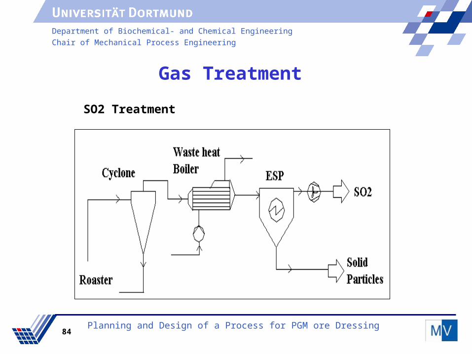
Gas Treatment
Planning and Design of a Process for PGM ore Dressing
SO2 Treatment
Department of Biochemical- and Chemical Engineering
Chair of Mechanical Process Engineering
85
Chair of Mechanical Process Engineering
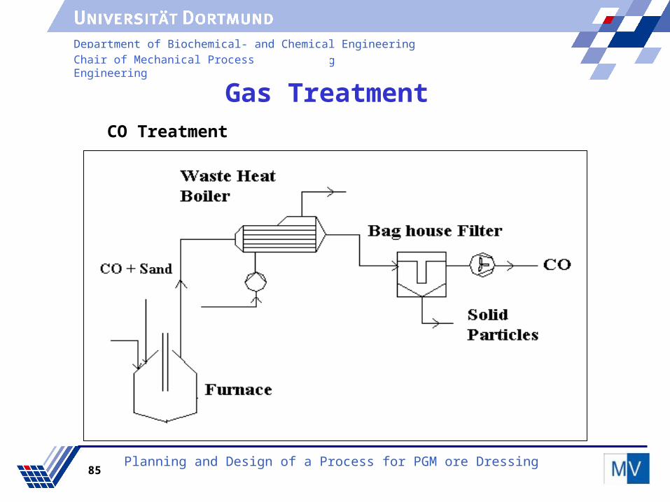
Gas Treatment
Planning and Design of a Process for PGM ore Dressing
CO Treatment
Department of Biochemical- and Chemical Engineering
Chair of Mechanical Process Engineering
86
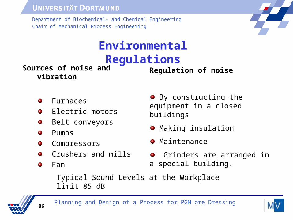
Environmental Regulations
Sources of noise and vibration
Furnaces
Electric motors
Belt conveyors
Pumps
Compressors
Crushers and mills
Fan
Typical Sound Levels at the Workplace limit 85 dB
Planning and Design of a Process for PGM ore Dressing
Regulation of noise
By constructing the equipment in a closed buildings
Making insulation
Maintenance
Grinders are arranged in a special building.

Department of Biochemical- and Chemical Engineering
Chair of Mechanical Process Engineering
87
Safety
Introduction
Chemical plants contain a large variety of hazards
Safety layer
Automatic actions
Automatic actions
Physicalprotection
Physicalprotection
Plant emergency response
Plant emergency responsecommunity emergency
response
community emergency response
Controls and alarms
Controls and alarms
Processdesign
Processdesign
Planning and Design of a Process for PGM ore Dressing

Department of Biochemical- and Chemical Engineering
Chair of Mechanical Process Engineering
88
Safety
Planning and Design of a Process for PGM ore Dressing
C.S.T.R

Department of Biochemical- and Chemical Engineering
Chair of Mechanical Process Engineering
89
Pressure across bag house
2000 Pa
Superficial gas velocity
0.05 m/s
Area required for filtration
2130 m2
Length of one bag 5 m
Number of chambers
22
Vertical height of plates
5 m
Horizontal length of plates
5 m
Wire Diameter 0,0025 m
Distance plate to plate
0,3 m
Collection Area 454,78 m2
Number of plates 11 plates
Gas Treatment Results
Planning and Design of a Process for PGM ore Dressing
Baghouse Filter ESP

Department of Biochemical- and Chemical Engineering
Chair of Mechanical Process Engineering
90
Cost Estimation and Overall Review
By
Amarnath Reddy
Planning and Design of a Process for PGM ore Dressing

Department of Biochemical- and Chemical Engineering
Chair of Mechanical Process Engineering
91
Cost Estimation
Contents
Estimating Fixed capital cost
Estimating Total production cost/annum
Income incurred per year
Pay back period
Analysis
Planning and Design of a Process for PGM ore Dressing

Department of Biochemical- and Chemical Engineering
Chair of Mechanical Process Engineering
92
Cost Estimation
Total Capital Investment
Fixed Capital Investment Working Capital Investment
Direct Costs Indirect Costs
Planning and Design of a Process for PGM ore Dressing

Department of Biochemical- and Chemical Engineering
Chair of Mechanical Process Engineering
93
Total capital investment
Fixed capital investment = P.E.C+O.D.C+I.D.C+Contingencies
P.E.C=Purchases Equipment Cost
O.D.C=Other Direct Costs
I.D.C=Indirect Cost
Planning and Design of a Process for PGM ore Dressing
Total capital investment=Fixed Capital investment+Total production costs

Department of Biochemical- and Chemical Engineering
Chair of Mechanical Process Engineering
94
Purchased Equipment costUnits Purchased Equipment cost
Million $
Communition 10.55
Flotation 8.49
Pyrometallurgy 6
Hydrometallurgy 1.72
Thickening and filtering 0.89
water treatment 6.3
Conveying 0.23
Pumps 0.74
Total P.E.C 35,8
Planning and Design of a Process for PGM ore Dressing

Department of Biochemical- and Chemical Engineering
Chair of Mechanical Process Engineering
95
Other Direct CostsPurchased EquipmentInstallationInsulation
Instrumentation and Controls
Piping
Electrical Installations
Building Including Services
Yard Improvements
Service Facilities
Land
45% PEC
9%PEC
13%PEC
31%PEC
13%PEC
47%PEC
15% PEC
30%PEC6%PEC
O.D.C=$118million
Other Direct costs
Planning and Design of a Process for PGM ore Dressing

Department of Biochemical- and Chemical Engineering
Chair of Mechanical Process Engineering
96
Production Costs
Manufacturing Costs = Direct Production Costs + Fixed Charges +
Plant Overhead Costs
Total Product Cost = Manufacturing Cost + General Expenses
Direct Production Costs million $/year
Raw Materials 206,4Operating Labor 10
Supervisory & clerical labor 1,5Electricity 22,5
Maintenance and Repairs 9,8Operating Supplies 1,46

Department of Biochemical- and Chemical Engineering
Chair of Mechanical Process Engineering
97
Fixed Chargesmillion $/year
Depreciation Rate 16,30Local Taxes 4,80
Insurance 1,60
Plant Overhead Costs
Plant Overhead Costs 12,80
General Expenses
Administrative Costs 2,50Research and Development 15,20
Production Costs

Department of Biochemical- and Chemical Engineering
Chair of Mechanical Process Engineering
98
Production Costs
Raw Materials (58.4 %)
Other Direct ProductionCosts(21.5%)
Fixed Charges (6.5%)
Plant Overhead Costs (7.9%)
General Expenses (5.7%)
58.4%
21.5%6.5%7.9%
5.7%
Total Production cost =$305million
Working capital/annum
Planning and Design of a Process for PGM ore Dressing
Department of Biochemical- and Chemical Engineering
Chair of Mechanical Process Engineering
99
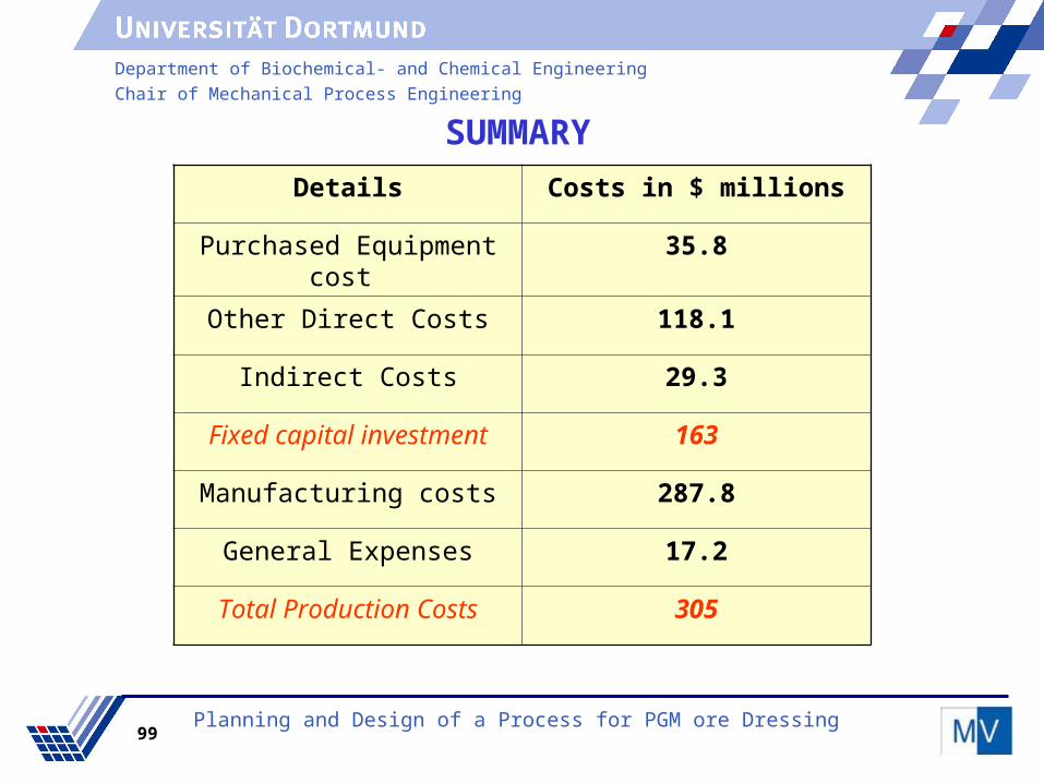
SUMMARY
Details Costs in $ millions
Purchased Equipment cost 35.8
Other Direct Costs 118.1
Indirect Costs 29.3
Fixed capital investment 163
Manufacturing costs 287.8
General Expenses 17.2
Total Production Costs 305
Planning and Design of a Process for PGM ore Dressing

Department of Biochemical- and Chemical Engineering
Chair of Mechanical Process Engineering
100
Income incurred /year
Number of kgs Produced/year = 22817 kg/year
Selling price Per Kg = $ 17000 per kg
Gross Earnings = Total Income – Total Product Cost = $ 82.6 million
Net Profit = Gross Earnings – Taxes = $ 61,9 million/year
Cost analysis
maintenance cost increases every year by 5%
50% of the initial investment is from banks
30% from the share holders
Planning and Design of a Process for PGM ore Dressing

Department of Biochemical- and Chemical Engineering
Chair of Mechanical Process Engineering
101
Analysis
Planning and Design of a Process for PGM ore Dressing

Department of Biochemical- and Chemical Engineering
Chair of Mechanical Process Engineering
102
Analysis
Planning and Design of a Process for PGM ore Dressing

Department of Biochemical- and Chemical Engineering
Chair of Mechanical Process Engineering
103
Analysis
Planning and Design of a Process for PGM ore Dressing
The Pgms Price is expected to be 2005
The pay back period
The pay back period for share holder
Bank installment clearence
= $25000 per kg
= 3 years for the owners
= 4 years
= 5 years

Department of Biochemical- and Chemical Engineering
Chair of Mechanical Process Engineering
104
Overall Review Overall Review
Planning and Design of a Process for PGM ore Dressing

Department of Biochemical- and Chemical Engineering
Chair of Mechanical Process Engineering
105
Overall review
Planning and Design of a Process for PGM ore Dressing
Advantages of our process
It can handle Chromite bearing ores too.
Off gas can be directly sold with minimum treatment
it is an economically feasible plant because break even point is just around 3 years
99Hydrometallurgy
96Pyrometallurgy
89.5Concentration
% Pgms RecoveryUnit
Final Concentration of PGM is 57%

Department of Biochemical- and Chemical Engineering
Chair of Mechanical Process Engineering
106
Planning and Design of a Process for PGM ore Dressing
Tutors
Dr.-Ing. Helmut Wiggers
Dipl.-Ing. Frank Landwehr
Dipl.-Ing. Daniel Feggeler
Dipl.-Ing. Sascha Groom
Tutors
Dr.-Ing. Helmut Wiggers
Dipl.-Ing. Frank Landwehr
Dipl.-Ing. Daniel Feggeler
Dipl.-Ing. Sascha Groom
Thankyou very much
Reference
Prof. Dr. techn. Peter Walzel
Co-reference
Prof. Dr. Gabriele Sadowski
Reference
Prof. Dr. techn. Peter Walzel
Co-reference
Prof. Dr. Gabriele Sadowski

Department of Biochemical- and Chemical Engineering
Chair of Mechanical Process Engineering
107
Planning and Design of a Process for PGM ore Dressing