Department for Environmental Protection Division...
35
INFORMATIONAL COPY Reprinted June, 1999 1 DEPARTMENT FOR NATURAL RESOURCES AND ENVIRONMENTAL PROTECTION Department for Environmental Protection Division of Water (401 KAR 4:030) RELATES TO: KRS 151.250 PURSUANT TO: KRS 151.125, 224.033(17), 224.045-(6)(b), 13.082 SUPERSEDES: DOW-Rg-2 NECESSITY AND FUNCTION: This regulation is necessary to establish minimum design criteria for dams and associated structures constructed in Kentucky. Section 1. This regulation applies to all dams as defined by KRS 151.100 and to all other impounding obstructions which might create a hazard to life or property. Section 2. Except as modified in this regulation, the procedures outlined by the latest edition of "Design of Small Dams" (Second Edition, 1973), available from the U.S. Government Printing Office and the Bureau of Reclamation, herein filed by reference, shall be the minimum criteria. Section 3. The Division of Water Engineering Memorandum No. 5 outlined as follows: Section A. Definitions; Section B. Structure Classification; Section C. Hydrologic Criteria; Section D. Sediment Storage; Section E. Principal Spillways; Section F. Emergency Spillways; Section G. Earth Embankments; and Section E. Utilities Under Embankments; is hereby incorporated by reference and made a part of this regulation as if fully set out herein. Copies are available from the Division of Water upon request. Section 4. Structure types not generally used in Kentucky, i.e., gravity, buttress, steel, timber, etc., will be considered on an individual basis and reviewed in accord with prevailing practices that are currently accepted by the engineering profession. Section 5. In all cases the safety of the structure, the water and/or other material impounded therein, property and human life will be the principal governing factors. Under no circumstances will the proposed use of the structure and its contents, or the cost of providing an unquestionably safe structure be allowed to assume precedence over the possible hazard involved. Section 6. Structures which are to be repaired or reconstructed must be made to conform to the criteria established by this regulation. Section 7. Each of the following stated criteria indicates whether the limit is a maximum or minimum limit and is not to be construed as being satisfactory design criteria at all sites. Professional judgment, state laws and regulations, investigations, or analysis may dictate more conservative criteria.
-
Upload
hoangnguyet -
Category
Documents
-
view
217 -
download
2
Transcript of Department for Environmental Protection Division...
INFORMATIONAL COPYReprinted June, 1999
1
DEPARTMENT FOR NATURAL RESOURCES AND ENVIRONMENTAL PROTECTIONDepartment for Environmental Protection
Division of Water(401 KAR 4:030)
RELATES TO: KRS 151.250PURSUANT TO: KRS 151.125, 224.033(17), 224.045-(6)(b), 13.082SUPERSEDES: DOW-Rg-2NECESSITY AND FUNCTION: This regulation is necessary to establish minimum design
criteria for dams and associated structures constructed in Kentucky.
Section 1. This regulation applies to all dams as defined by KRS 151.100 and to all otherimpounding obstructions which might create a hazard to life or property.
Section 2. Except as modified in this regulation, the procedures outlined by the latestedition of "Design of Small Dams" (Second Edition, 1973), available from the U.S. GovernmentPrinting Office and the Bureau of Reclamation, herein filed by reference, shall be the minimumcriteria.
Section 3. The Division of Water Engineering Memorandum No. 5 outlined as follows:Section A. Definitions; Section B. Structure Classification; Section C. Hydrologic Criteria; SectionD. Sediment Storage; Section E. Principal Spillways; Section F. Emergency Spillways; Section G.Earth Embankments; and Section E. Utilities Under Embankments; is hereby incorporated byreference and made a part of this regulation as if fully set out herein. Copies are available from theDivision of Water upon request.
Section 4. Structure types not generally used in Kentucky, i.e., gravity, buttress, steel,timber, etc., will be considered on an individual basis and reviewed in accord with prevailingpractices that are currently accepted by the engineering profession.
Section 5. In all cases the safety of the structure, the water and/or other material impoundedtherein, property and human life will be the principal governing factors. Under no circumstanceswill the proposed use of the structure and its contents, or the cost of providing an unquestionablysafe structure be allowed to assume precedence over the possible hazard involved.
Section 6. Structures which are to be repaired or reconstructed must be made to conform tothe criteria established by this regulation.
Section 7. Each of the following stated criteria indicates whether the limit is a maximum orminimum limit and is not to be construed as being satisfactory design criteria at all sites.Professional judgment, state laws and regulations, investigations, or analysis may dictate moreconservative criteria.

INFORMATIONAL COPYReprinted June, 1999
2
Section 8. (1) Approval of all plans and specifications shall be divided into two (2) distinctparts:
(a) Issuance of a construction permit pursuant to KRS151.250 shall constitute approval of the finalengineering documents to allow construction to bestarted; and
(b) Final written approval by the department upon receiptof the "as-built" plans and specifications willconstitute approval to impound.
(2) No approval to impound water and/or other material is implied or is in any way granteduntil the "as-built" plans and specifications have been approved, an on-site inspection has beenmade, and a written statement of approval issued. It is recommended that the owner and/or hisengineer contact this division before initiation of final design for a pre-design conference.
Section 9. All plans and specifications submitted for consideration must bear the seal andsignature of the responsible engineer as defined in KRS 322.010 (2), except officers and employeesof the United States Government while engaged in engineering for the government. Each sheet ofthe drawings shall bear the seal and signature of the engineer or engineers responsible for itspreparation.
Section 10. All structures, other-than Class A as defined in Engineering Memorandum No.5 (2-1-75) shall have a complete sub-surface investigation and soil analysis submitted as an integralpart of the drawings.
Section 11. (1) Elevation area capacity data and elevation discharge data must be submittedas a part of the plans for each structure. This elevation area capacity data shall give the area andcapacities from the elevation of the lowest point in the impoundment area to at least the elevation atthe top of the dam. When the configuration of the structure will not allow the elevation dischargerelationship to be developed by methods accepted as standard by the engineering profession, thestructure must provide the storage necessary to contain the entire storm runoff without probabledamage to the structure or creating an unacceptable hazard to life or property.
(2) When this required basic information is furnished by the responsible design engineer,the Division of Water will upon request assist the engineering in preparing the floodroutingsrequired by Engineering Memorandum No. 5.
(3) In the event that the elevation area capacity data is not furnished or the floodroutingsshow that insufficient floodwater storage has been provided, the plans will be returned to the designengineer without being approved.
INFORMATIONAL COPYReprinted June, 1999
3
Section 12. All information concerning elevations shall refer to mean sea level and the useof assumed elevations for any purpose is prohibited. Should an error in either the horizontalcontrol or vertical control become known during construction, the necessary information to correctthe distances and the elevations shall be referred to on the first sheet of the "as-built" drawings orreferred to in the index. Clearly marked reference points and bench marks shall be maintained atthe job site by the responsible engineer until final written approval is received.
Section 13. Unless waived in writing by the department, no structure shall be approvedunless a positive means is provided to pass water through the structure in sufficient quantity tosatisfy the needs of downstream users and to empty the reservoir within a reasonable length of time. Conditions considered in determining downstream water requirements and required minimum timeto empty the impoundment shall be determined by the responsible engineer and referred to on thedrawings.
Section 14. Construction supervision and inspection must be performed by or under thedirection of the design engineer. Unless otherwise directed by the department the engineer shallsubmit monthly progress reports on forms to be supplied by the department. Copies of all testingreports shall be submitted with the progress reports.
Section 15. All "as-built" documents shall be submitted by the responsible engineer in theform of permanent type drawings of a standard and uniform size. Variations in size will bepermitted for federal agencies in order that they may use their standard drawings. Drawings that donot conform to standard practices or drawings that are not easily legible will not be accepted.
Section 16. Because of the department's statutory duty to review federal projects for theCommonwealth under KRS 151.220, the United States Army Corps of Engineers is exempt fromthe provisions of this regulation and KRS 151.250.
ADOPTED: March 12, 1975RECEIVED BY LRC: March 13, 1975 at 2:31 p.m.

INFORMATIONAL COPYReprinted June, 1999
4
DOW/CP-021Revised 10/80
DEPARTMENT FOR NATURAL RESOURCES AND ENVIRONMENTAL PROTECTIONDepartment for Environmental Protection
Division of Water(401 KAR 4:040)
RELATES TO: KRS 151.250PURSUANT TO: KRS l5l.l25, 224.033(17), 224.045(6)(b), 13.082SUPERSEDES: DOW-Rg-3NECESSITY AND FUNCTION: This regulation is necessary to exempt certain dams,
embankments, levees, dikes, bridges, fills, and other stream obstructions proposed in conjunctionwith surface and deep mining from the provisions of KRS Chapter 151 to avoid duplication ofeffort within the Department for Natural Resources and Environmental Protection.
Section 1. As a part of the routine processing of application for permits for surface miningand the surface effects of deep mining, the engineering staff of the Division of Permits, Bureau ofSurface Mining Reclamation and Enforcement, reviews all designs for dams, embankments, levees,dikes, bridges, fills, and other stream obstructions proposed in conjunction with surface or deepmining and, whereas a substantial number of such dams, embankments, levees, dikes, bridges, fills,and other stream obstructions are of such a size, type, and location as to present no potentialhazard to life and/or property; this regulation exempts from the provision of KRS 151.250 all suchdams, etc., as described above, except those dams which come within the hazard classificationcontained in Division of Water Engineering Memorandum No. 5 (2-1-75), and those obstructionsas described, which, in the professional judgment of the Division of Permits engineering staff,present a potential hazard to life and/or property. Copies of Engineering Memorandum No. 5 (2-1-75) are available upon request from the Division of Water.
Section 2. Certified, "as-built" engineering plans for all dams which impound or divert waterand/or other material and which (i) are twenty-five (25) feet or more in height or (ii) have animpounding capacity of fifty (50) acre-feet or more at the lowest point on the top of the dam mustbe forwarded by the Division of Permits to the Division of Water for inclusion in the Dam SafetyProgram required by KRS 151.295(c). Height is measured from the natural bed of the stream orwatercourse at the downstream toe of the barrier to the low point in the top of the dam.
ADOPTED March 12, 1975RECEIVED BY LRC: March 13, 1975, at 2:31 p.m.
Department for Natural Resources and Environmental ProtectionDivision of Water
Engineering Memorandum No. 5
INFORMATIONAL COPYReprinted June, 1999
5
PAGESECTION A - DEFINITIONS 6
SECTION B - STRUCTURE CLASSIFICATION 8
SECTION C - HYDROLOGIC CRITERIA 11
SECTION D - SEDIMENT STORAGE 15
SECTION E - PRINCIPAL SPILLWAYS 16
SECTION F - EMERGENCY SPILLWAYS 25
SECTION G - EARTH EMBANKMENTS 34
SECTION H - UTILITIES UNDER EMBANKMENTS 35
Department for Natural Resources and Environmental ProtectionDivision of Water
Engineering Memorandum No. 5
INFORMATIONAL COPYReprinted June, 1999
6
SECTION A - DEFINITIONS
A spillway is an open or closed channel, or both, used convey water from a reservoir. It maycontain gates, either manually or automatically controlled, to regulate discharge of water.
The principal spillway is the ungated spillway designed convey the water from the retarding pool atrelease rates established for the structure.
The emergency spillway of a dam is the spillway designed convey water in excess of thatimpounded for flood control or other beneficial purposes.
The retarding pool is the reservoir space allotted to the temporary impoundment of floodwater. Itsupper limit is the elevation of the crest of the emergency spillway.
Retarding storage is the volume in the retarding pool.
The sediment pool is the reservoir space allotted to the accumulation of submerged sediment duringthe life of the structure.
The sediment storage is the volume allocated to total sediment accumulation.
The sediment pool elevation is the elevation of the surface the anticipated sediment accumulation atthe dam.
An earth spillway is an unvegetated open channel spillway in earth materials.
A vegetated spillway is a vegetated open channel spillway in earth materials.
A ramp spillway is a vegetated spillway constructed on the downstream face of an earth dam.
A rock spillway is an open channel spillway in durable rock materials.
A control-section in an open channel spillway is that section where accelerated flow passes throughcritical depth.
The inlet channel of an emergency spillway is the channel upstream from the control section.
Department for Natural Resources and Environmental ProtectionDivision of Water
Engineering Memorandum No. 5
INFORMATIONAL COPYReprinted June, 1999
7
The exit channel of an emergency spillway is that portion of the channel downstream from thecontrol section which conducts the flow safely to a point where it may be released withoutjeopardizing the integrity of the structure.
The emergency spillway-hydrograph is that hydrograph used to establish the minimum designdimensions of the emergency spillway.
The freeboard hydrograph is the hydrograph used to establish the minimum elevation of the top ofthe dam.
Joint extensibility is the length of a pipe joint measured from the center of the gasket to the point offlare of the bell ring or collar when the joint is engaged.
Joint gap is the longitudinal dimension between the end face of the spigot end of a pipe joint andthe corresponding face of the bell end of the connecting pipe. It does not include the beveledportions designed for sealing compounds.
The rotation capacity of a pipe joint is the maximum angular deflection possible for the jointwithout binding or loss of watertightness.
The maximum possible high water is the maximum elevation of the water surface that might beattained either above or below the structure, which may be attributed to structure.
The height of the embankment is the distance in feet measured from the natural bed of the stream orwatercourse at the downstream toe of the barrier to the low point in the top of the dam.

Department for Natural Resources and Environmental ProtectionDivision of Water
Engineering Memorandum No. 5
INFORMATIONAL COPYReprinted June, 1999
8
SECTION B - STRUCTURE CLASSIFICATIONS
PAGEI. CLASS OF STRUCTURES 9
A. Class (A) - Low Hazard 9
B. Class (B) - Moderate Hazard 9
C. Class (C) - High Hazard 9
II. STRUCTURES IN SERIES 10
Department for Natural Resources and Environmental ProtectionDivision of Water
Engineering Memorandum No. 5
INFORMATIONAL COPYReprinted June, 1999
9
SECTION B - STRUCTURE CLASSIFICATION
In determining structure classification, a number of factors must be considered. Consideration must be given to the damage that might occur to existing and future developmentsdownstream resulting from a sudden breach of the earth embankment and the structuresthemselves. The effect of failure on public confidence is an important factor. State and localregulations and the responsibility of the involved public agencies must be recognized. The stabilityof the spillway materials, the physical characteristics of the site and valley downstream, and therelationship of the site to industrial and residential areas all have a bearing on the amount ofpotential damage in the event of a failure.
Structure classification is determined by the above conditions. It is not determined by thecriteria selected for design.
1. CLASS OF STRUCTURES
The following broad classes of structures are established to permit the association of criteriawith the damage that might result from a sudden major breach of the structure.
A. Class (A) - Low Hazard
This classification may be applied for structures located such that failure would cause lossof the structure itself but little or no additional damage to other property. Such structures willgenerally be located in rural or agricultural areas where failure may damage farm buildings otherthan residences, agricultural lands, or county roads.
B. Class (B) - Moderate Hazard
This classification may be applied for structures located such that failure may causesignificant damage to property and project operation, but loss of human life is not envisioned. Suchstructures will generally be located in predominantly rural agricultural areas where failures maydamage isolated homes, main highways or major railroads, or cause interruption of use or service ofrelatively important public utilities.
C. Class (C) - High Hazard
This classification must be applied for structures located such that failure may cause loss oflife, or serious damage to houses, industrial or commercial buildings, important public utilities, main
Department for Natural Resources and Environmental ProtectionDivision of Water
Engineering Memorandum No. 5
INFORMATIONAL COPYReprinted June, 1999
10
highways or major railroads. This classification must be used if failure would cause probable lossof human life.
The responsible engineer shall determine the classification of the proposed structure afterconsidering the characteristics of the valley below the site and probable future development. Establishment of minimum criteria does not preclude provisions for greater safety when deemednecessary in the judgment of the engineer. Considerations other than those mentioned in the aboveclassifications may make it desirable to exceed the established minimum criteria. A statement ofthe classification established by the responsible engineer shall be clearly shown on the first sheet ofthe plans.
II. STRUCTURES IN SERIES
When structures are spaced so that the failure of an upper structure could endanger thesafety of a lower structure, the possibility of a multiple failure must be considered assigning thestructure classification of the upstream structure.
Additional safety can be provided in either structure by (1) increasing the retarding storageand/or (2) increasing the emergency spillway capacity.

Department for Natural Resources and Environmental ProtectionDivision of Water
Engineering Memorandum No. 5
INFORMATIONAL COPYReprinted June, 1999
11
SECTION C - HYDROLOGIC CRITERIA
PAGEI. RUNOFF 12
A. Structure in Series 12
II. PRINCIPAL SPILLWAY 13
III. EMERGENCY SPILLWAY 13
IV. FREEBOARD 13
V. MINIMUM HYDROLOGIC CRITERIA 14

Department for Natural Resources and Environmental ProtectionDivision of Water
Engineering Memorandum No. 5
INFORMATIONAL COPYReprinted June, 1999
12
SECTION C - HYDROLOGIC CRITERIA
I. RUNOFF
Procedures for hydrologic design as contained in the USDA Soil Conservation ServiceNational Engineering Handbook, Section 4 "Hydrology" will be accepted. Copies of thispublication are available from the U. S. Government printing office.
The specific references for runoff determination are found in Chapter 10. All runoffvolumes for design purposes will be based on Antecedent Moisture Condition II or greater. Chapter 21 contains hydrologic procedures for determining principal spillway capacities, retardingstorage, and emergency spillway and freeboard hydrographs.
A. Structures in Series
For the design of a lower structure in a series, if the total drainage area above a lowerstructure exceeds 10 square miles and Section B-II of this memorandum applies, it is necessary toapply two sets of storms for development of both the emergency spillway and the freeboardhydrographs.
The first set of design storms will be selected for the development of the uncontrolleddrainage area above a lower structure. The dimensions of the emergency spillway for a lowerstructure under this condition will be determined by reservoir routings of hydrographs developedfor each storm.
The second set of design storms will be selected for the entire drainage area above thelower structure. Each design storm rainfall is determined by using this area in the areal adjustmentof rainfall amounts. These design storm durations are determined by using the time ofconcentration of this area assuming no upper structures are in place. The design stormhydrographs will be routed through the emergency spillways of the upstream structures and theoutflow routed to the lower structure and combined with the hydrograph for the uncontrolled area. The dimensions of the emergency spillway for a lower structure under this condition will also bedetermined by reservoir routings of the hydrographs developed for each storm.
The design storm imposing the most severe flow condition at the lower structure will beused.
Department for Natural Resources and Environmental ProtectionDivision of Water
Engineering Memorandum No. 5
INFORMATIONAL COPYReprinted June, 1999
13
II. PRINCIPAL SPILLWAY
The retarding storage and associated principal spillway discharge will be such that theemergency spillway will not operate more frequently than indicated in Table F-I, Section B,Emergency Spillways. The inflow hydrograph or the minimum runoff volume for developing thebalance between principal spillway capacity and retarding storage will be determined by proceduresin Chapter 21, Section 4, SCS National Engineering Handbook. In areas where streamflow recordscan be regionalized and transposed to ungaged watersheds (based on the volume-duration-probability analyses), the Division of Water will authorize the use of these data for developing theprincipal spillway capacity and retarding storage. When other streamflow data are used, sufficientdocumentation must be prepared to show how these values were determined.
In the determination of the retarding storage and the principal spillway capacity, it isassumed that the initial reservoir stage is at the crest of the principal spillway.
III. EMERGENCY SPILLWAY
The emergency spillway hydrograph will be routed through the reservoir starting with awater surface at the elevation of the principal spillway inlet or at the water surface elevation after10 days of drawdown, whichever is higher. The 10-day drawdown will be computed from themaximum water surface elevation which would be attained during the passage of the minimumprincipal spillway design runoff for that class of structure.
IV. FREEBOARD
The freeboard hydrograph for class (A) and (B) structures will be routed through thereservoir starting at the same water surface elevation as for the emergency spillway hydrograph. The routing of the freeboard hydrograph for class (C) structures may be started at the crest of theprincipal spillway.

Department for Natural Resources and Environmental ProtectionDivision of Water
Engineering Memorandum No. 5
INFORMATIONAL COPYReprinted June, 1999
14
V. MINIMUM HYDROLOGIC CRITERIA
Minimum hydrologic criteria are established for the development of each hydrograph asfollows:
Emergency Spillway Hydrograph
Class (A) A 100P = PClass (B) B 100 100P = P + 0.12 x (PMP - P )Class (C) C 100 100P = P + 0.26 x (PMP - P )
Freeboard Hydrograph
Class (A) )P - (PMP x 0.12 + P = P 100100A
Class (B) PB = P100 + 0.40 x (PMP - P100 )Class (C) PC = PMP
in which P denotes 6-hour design rainfall, P100 refers to 6-hour, 100-year precipitation, andPMP represents 6-hour Probable Maximum Precipitation.
The above values may be obtained from the "Rainfall Frequency Atlas of the United Statesfor Durations from 30 Minutes to 24 Hours and Return Periods from 1 to 100 Years", TechnicalPaper No. 40, Weather Bureau, U. S. Department of Commerce, Washington, D. C., and "Two ToTen-Day Precipitation For Return Periods of 2 To 100 Years In Contiguous United States",Technical Paper No. 49, Weather Bureau, U. S. Department of Commerce, Washington, D. C.These values may also be found in Division of Water, Kentucky Department for Natural Resourcesand Environmental Protection, Engineering Memorandum No. 2, “Rainfall Frequency Values forKentucky.”
When hydrographs are required for drainage areas with times of concentration in excess of6 hours, the above must be modified to reflect the appropriate storm period.
The establishment of the above criteria does not eliminate the need for sound engineeringjudgment but only establishes the lowest limit of design considered acceptable.
It is the responsibility of the design engineer to classify the structure and to determine if thedesign requirements are in excess of the minimum.
Department for Natural Resources and Environmental ProtectionDivision of Water
Engineering Memorandum No. 5
INFORMATIONAL COPYReprinted June, 1999
15
SECTION D - SEDIMENT STORAGE
Where the primary purpose is floodwater retardation or water storage or combinationthereof, reservoirs are normally designed on the basis of a 50 to 100-year useful life. In order toassure full effectiveness, capacity must be provided in the reservoir to offset depletion due tosediment accumulation for a period equal to its design life.

Department for Natural Resources and Environmental ProtectionDivision of Water
Engineering Memorandum No. 5
INFORMATIONAL COPYReprinted June, 1999
16
SECTION E - PRINCIPAL SPILLWAYS
PAGE
I. CAPACITY OF PRINCIPAL SPILLWAYS 17
II. ELEVATION OF PRINCIPAL SPILLWAYS 17
III. DESIGN OF PRINCIPAL SPILLWAYS 18
A. Layout 18
B. Conduits 18
1. Rigid Pipe 18
a. Minimum inside Diameters on
Yielding Foundations 19
b. Minimum Inside Diameters on
Rock Foundations 20
2. Corrugated Metal Pipe 20
C. Joints 21
D. Anti-Seep Collars 22
E. Cantilever Outlets 23
F. Trash Racks 23
G. Anti-Vortex Device 23
H. Drawdown Facilities 24

Department for Natural Resources and Environmental ProtectionDivision of Water
Engineering Memorandum No. 5
INFORMATIONAL COPYReprinted June, 1999
17
SECTION E - PRINCIPAL SPILLWAYS
All component parts of the principal spillway except attached gates and trash racks will beof equal durability. The structural design criteria and detailing of such spillways will conform torecognized standards and codes of practice.
I. CAPACITY OF PRINCIPAL SPILLWAYS
The required capacity of the principal spillway depends on (1) the benefits that accrue to thereduction of the discharge rate, (2) damages that may result from prolonged storage in the retardingpool, (3) damages that may result from prolonged outflow, (4) the possibility of occurrence ofsignificant runoff from two or more consecutive storm events within the time required to empty theretarding pool, and (5) limitations in water rights or other legal requirements.
It is desirable that the retarding pool be emptied in ten (10) days or less. It may be assumedthat this requirement has been met if eighty (80) percent of the maximum volume of retardingstorage has been evacuated in the ten (10) day period. The use of a longer period must be justifiedby an appraisal of the considerations listed above.
The discharge through gated outlets will not be considered in determining the emptyingtime of the retarding pool unless a specific reservoir operation plan has been approved and includedin the plans.
II. ELEVATION OF PRINCIPAL SPILLWAYS
The crest of a single stage principal spillway will be placed at the elevation of the 50-yearsediment pool except where a higher elevation is justified. For a two stage principal spillway, thecrest of the lower inlet will be set at the same elevation as for a single stage structure. When aperiod greater than 50 years has been used for evaluation, it is recognized that structural changesmay be necessary to make the structure function effectively during the latter part of its life.
For dry dams, the riser will be designed to permit design discharge at the 50-year sedimentpool elevation with provisions for discharging water at lower elevations to satisfy the functionalrequirements of the structure. Flood routings must start at or above the anticipated elevation of the50-year sediment pool.
When water is stored for beneficial use, the elevation of the lowest ungated inlet of theprincipal spillway will be determined by the volume, area, or depth of water required for theplanned purpose or purposes in addition to the anticipated sediment storage during the design life.

Department for Natural Resources and Environmental ProtectionDivision of Water
Engineering Memorandum No. 5
INFORMATIONAL COPYReprinted June, 1999
18
III. DESIGN OF PRINCIPAL SPILLWAYS
A. Layout
The barrel of drop inlets should be straight in alignment when viewed in plan. Any requiredchanges in alignment will be accomplished by angle changes at joints which do not exceed fivedegrees or by special elbows having a radius equal to or greater than the diameter or width of theconduit. Thrust blocks of adequate strength will be provided where special pipe elbows are used. They will be designed to distribute the thrust, due to change in direction, for the maximum possibledischarge.
Drop inlet barrels will be installed with sufficient camber to insure free drainage to theoutlet of all parts of the barrel at the time of construction and under the maximum anticipatedfoundation consolidation.
B. Conduits
All conduits under an earth embankment must support the external loads imposed with anadequate factor of safety. They must withstand the internal hydraulic pressures without leakageunder full external load and settlement. They must convey water at the design velocity withoutdamage to the interior surface of the conduit.
Principal spillway conduits under earth dams must be designed to support fill heights greaterthan the original constructed height where there is a reasonable possibility that it may becomedesirable to raise the embankment height at a later date to incorporate additional storage.
Principal spillway conduits are to be of reinforced concrete pipe, cast-in-place reinforcedconcrete, or ductile iron pipe, unless corrugated steel or welded steel pipe is used in accordancewith subsection III-B-2, which follows:
1. Rigid Pipe
Rigid drop inlet barrels will be designed as positive projecting conduits. For reinforcedConcrete Water Pipe Steel Cylinder Type, Prestressed, meeting specification AWWA C-301, the 3-edge bearing strength at the first 0.001 inch crack will be used in the design analysis with a factor ofsafety of at least one.
For reinforced Concrete Water Pipe - Steel Cylinder Type - Not Prestressed meetingspecification AWWA C-300, for Reinforced Concrete Water Pipe - Non-cylinder Type - NotPrestressed meeting specification AWWA C-302, and other types of reinforced concrete pipe, the
Department for Natural Resources and Environmental ProtectionDivision of Water
Engineering Memorandum No. 5
INFORMATIONAL COPYReprinted June, 1999
19
3-edge bearing strength at the first 0.01 inch crack will be used in the design analysis with a factorof safety of at least 1.33.
Ductile Iron Pipe may be used as a principal spillway conduit under certain conditions. Fillheights and foundation conditions require special considerations such that each use will be checkedon an individual basis. Cradling or encasement in concrete may be required in most instances.
Elliptical or other systems of reinforcement requiring special orientation of pipe sections arenot permitted in pipe drop inlet barrels.
Reinforced concrete pipe, with or without cradles, will be designed to support at least 12feet of earth fill above the pipe at all points along the conduit.
These safety factors are for uniform conditions. They should be increased if the strengthand compressibility of the foundation are not reasonably uniform.
a. Minimum Inside Diameters on Yielding Foundations.
Class (A) dams: The minimum diameter of the principal spillway barrel will be 30 inchesexcept:
(1) Where a joint extension safety margin of 1.5 inches is used, in which case theminimum diameter is to be 18 inches for fill heights up to 50 feet and 24 inches for greater heights.
(2) Where the drop inlet is designed hydraulically in such a way that the flow in thebarrel under all possible conditions of discharge and foundation consolidation is positively knownto be open channel flow with the water surface in the conduit subject to atmospheric pressure only,in which case the minimum diameter will be 18 inches.
(3) Where corrugated metal pipe is used the principal spillway must be designed inaccordance with conditions presented in Section III-B-2 below.
Class (B) dams: The minimum diameter of the principal spillway barrel will be 30 inches,except where a joint extension safety margin of 1.5 inches is used, in which case the minimumdiameter will be 24 inches.
Class (C) dams: The minimum diameter of the principal spillway barrel will be 30 inches.
b. Minimum Inside Diameter on Rock Foundations
Department for Natural Resources and Environmental ProtectionDivision of Water
Engineering Memorandum No. 5
INFORMATIONAL COPYReprinted June, 1999
20
Class (A) , (B) , and (C) dams: The minimum diameter of the barrel of reinforced-concretepressure pipe drop inlets for class (1) dams is to be 18 inches for heights up to 50 feet and 24inches for heights greater than 50 feet, and 24 inches for all class (B) and (C) dams. The barrel andcradle or bedding are to rest directly on firm bedrock thick enough so that there is essentially nofoundation consolidation under the barrel. Under these conditions the cradle under the pipe neednot be articulated.
2. Corrugated Metal Pipe and Welded Steel Pipe
Principal spillways of corrugated metal pipe or welded steel pipe may be used for class (A)dams under the following conditions, all of which must be met:
a. The minimum diameter of the barrel will be 18 inches.
b. The height of fill over the pipe will be less than 25 feet.
c. Corrugated steel pipe is to be close riveted, asbestos treated, and asphalt coated,with watertight connecting bands. The minimum gage is to be that specified for 35 feet offill over the pipe.
d. Welded steel pipe conduits are to conform to ASTM specifications A53, A120,A135, A139, or A134 and are be structurally designed as rigid pipe. A joint extensionsafety margin of 1.5 inches is to be provided for conduits on yielding foundations. Weldedpipe is to be protected by an approved exterior coating.
e. Joints between lengths of corrugated steel or welded steel pipe, other than weldedjoints, are to electrically bridged on the outside of the pipe with insulated copper wire, #6AWG or larger, securely attach to uncoated pipe metal at both sides of the joint. Therequirement applies whether or not the cathodic protection is completed by the installationof anodes, etc. The wire should have a tough, waterproof insulation designed for directburial, with a rating of at least 600 volts. Bare wire and exposed pipe metal at the points ofconnection are to be thoroughly coated with a coating equivalent the original pipe coatingto prevent the entry of moisture.
f. Soil investigations for resistivity and pH of the subgrade and backfill materials to beadjacent to the conduit are to be made if corrugated steel or welded steel pipe is to be used. The resistivity measurements are to be made on saturated samples.
Department for Natural Resources and Environmental ProtectionDivision of Water
Engineering Memorandum No. 5
INFORMATIONAL COPYReprinted June, 1999
21
g. Cathodic protection is to be provided for welded steel pipe conduits according toapproved engineering criteria.
h. Cathodic protection meeting the above requirements is to be provided forcorrugated steel pipe in soil whose resistivity in a saturated condition is less than 4000ohms/cm³ or whose pH is lower than 5.0.
i. If cathodic protection for corrugated steel or welded steel pipe is not requiredaccording to the above criteria and is not installed during construction of the dam, pipe-to-soil potentials are to be measured within the first two (2) years after construction when thesoil around the conduit is estimated to be at its normal post-construction moisture content,and cathodic protection is to be installed if such measurements indicate it is needed.
C. JOINTS
Conduit joints will be designed and constructed to remain water tight under maximumanticipated hydrostatic head and maximum probable conditions of joint opening including theeffects of joint rotation and a margin of safety where required.
The required joint extensibility is equal to the unit horizontal strain in the earth adjacent tothe barrel, multiplied by the length (in inches) of the section of barrel between joints, plus theextension (in inches) due to calculated joint rotation, plus a margin of safety if required. A marginof safety of 0.5 inch is recommended. The required joint extensibility, plus the maximumpermissible joint gap equals the required joint length.
The calculation of the required joint extensibility for any particular dam and spillwaydepends, among other things, on the evaluation of the maximum potential foundation consolidationunder the spillway barrel. For Classes (B) and (C) dams, the consolidation will be estimated fromadequate foundation borings and samples, soil mechanics laboratory tests and engineering analysis.
For those Class (A) dams where undisturbed foundation samples are not taken for otherpurposes, approximate procedures based on soil classification and experience will be used forestimating foundation consolidation. When AWWA C-302 or other types of reinforced concretepipe are used, they will have rubber to steel joints.
Only joints incorporating a round rubber gasket set in a positive groove which will preventits displacement from either internal or external pressure under the maximum designed jointextensibility will be used on precast concrete pipe drop inlet barrels.
Department for Natural Resources and Environmental ProtectionDivision of Water
Engineering Memorandum No. 5
INFORMATIONAL COPYReprinted June, 1999
22
Articulation of the barrel will be provided at each joint in the barrel and at the junction ofthe barrel and the inlet (riser). Concrete bedding for pipe drop inlets need not be articulated:cradles will be articulated when on yielding foundations.
D. Anti-Seep Collars
All conduits through earth embankments, foundations, and abutments will be provided withanti-seep collars.
The minimum number of anti-seep collars will be determined by the size of collars and thelength of that portion of the conduit which lies in the saturated zone of earth embankment.
The following criteria will be used to determine the size and number of anti-seep collars.
Let V = the vertical projection and minimum horizontal projection of the anti-seepcollar in feet.
L = Length in feet of that portion of the barrel of a drop inlet or culvert lyingwithin the zone of saturation, measured from the downstream side of theriser to the toe drain, or point where phreatic line intercepts the conduit.
n = Number of anti-seep collars.
The length of the line of seepage is defined as the distance along the line of contact betweenthe earth embankment and the barrel and the anti-seep collars from the upstream end of the barrelto the point of intersection of the barrel and the phreatic line. The ratio of the length of the line ofseepage (L + 2 n V) to L will not be less than 1.15.
Anti-seep collars should be equally spaced, except where necessary to avoid pipe joints,along that portion of the barrel within the saturated zone at distances of not more than 25 feet.
In the absence of positive evidence to the contrary (for purposes of computing anti-seepcollar requirements) the location of the phreatic line in the earth dam embankment will be estimatedon the assumption that the foundation of the embankment is impervious or that it is fully saturated.
E. Cantilever - Outlets
Department for Natural Resources and Environmental ProtectionDivision of Water
Engineering Memorandum No. 5
INFORMATIONAL COPYReprinted June, 1999
23
The invert of cantilever outlets of pipe drop inlets or culverts at its lower end will be at leastone foot above the tailwater elevation of the downstream channel at maximum discharge.
Cantilever outlets will be supported on bents or piers and will extend a minimum of eightfeet beyond the bents or piers. The bents will be located downstream from the intersection of thedownstream slope of the earth dam embankment with the grade line of the channel below the dam. They will extend below the lowest elevation anticipated in the scour hole.
In determining the depth of the stilling basin, full consideration must be given to the totalenergy to be dissipated. The stilling basin will be excavated when soil conditions at thedownstream end of the cantilever outlet indicate that a stilling basin will not be readily formedwithout extensive erosion of channel banks or the embankment.
Adequate safeguards must be taken to insure that the seepage forces into the stilling basinwill not result in a piping failure.
F. Trash Racks
Trash racks will be designed and built to provide positive protection against clogging of thespillway at any point. The average velocity of flow through a clean trash rack will not exceed twofeet per second with the water elevation in the reservoir five feet above the top of the trash rack orat the crest of the emergency spillway whichever is lower. Velocity will be computed on the basisof the net area of opening through the rack.
For dry dams, a trash rack may be used in lieu of a ported concrete riser. The principalspillway trash rack will extend sufficiently above the anticipated sediment elevation at the inlet toprovide full design flow through the spillway with velocities through the net area of the trash rackabove the sediment elevation not in excess of two feet per second when the water surface in thereservoir is five feet above the top of the trash rack.
G. Anti-Vortex Device
All closed conduit principal spillways designed for pressure flow will have an adequate anti-vortex device.

Department for Natural Resources and Environmental ProtectionDivision of Water
Engineering Memorandum No. 5
INFORMATIONAL COPYReprinted June, 1999
24
H. Drawdown Facilities
The necessary drawdown facility for any dam may be made an integral part of the principalspillway structure if the principal spillway configuration warrants, but in no case will the drawdownfacility be allowed to be valved on the downstream side of the embankment. This precludes in anycase a wet line under pressure through the embankment.
This above stated requirement will be waived in the case of a water supply line through thedam but provision must be made for a positive shutoff on the upstream side of the structure.
Department for Natural Resources and Environmental ProtectionDivision of Water
Engineering Memorandum No. 5
INFORMATIONAL COPYReprinted June, 1999
25
SECTION F - EMERGENCY SPILLWAYS
PAGEI. SPILLWAY REQUIREMENTS 26
A. Capacity of Emergency Spillways 26
B. Elevation of the Crest of the Emergency Spillway 26
C. Hydraulic Design 27
II. VEGETATED AND EARTH EMERGENCY SPILLWAYS 27
A. Layout 28
1. Special Precautions for Class C Structures 29
B. Frequency of Use of Earth and Vegetated Emergency Spillways 29
C. Permissible Velocity in Vegetated or Earth Emergency Spillways 30
1. Vegetated Emergency Spillways 31
a. Ramp Spillways 31
2. Earth Emergency Spillways 32
III. ROCK EMERGENCY SPILLWAYS 33
IV. STRUCTURAL EMERGENCY SPILLWAYS 33
V. WATER SURFACE PROFILE 33
Department for Natural Resources and Environmental ProtectionDivision of Water
Engineering Memorandum No. 5
INFORMATIONAL COPYReprinted June, 1999
26
SECTION F - EMERGENCY SPILLWAYS
Emergency spillways are provided to convey large flows safely past an earth embankment. They are usually open channels excavated in earth or rock or constructed of compactedembankment or reinforced concrete.
An emergency spillway must be provided for each structure, unless the principal spillway islarge enough to pass the routed freeboard hydrograph discharge and the trash that comes to it. Aconduit type principal spillway having a barrel with a cross-sectional area of 36 square feet or more,an inlet which will not clog, and an elbow designed to facilitate the passage of trash, is a minimumsize and design that may be utilized without an emergency spillway. If a principal spillway of thistype and size is not provided, danger from clogging requires the use of an emergency spillwayregardless of the volume of storage provided.
A single uncontrolled open channel spillway may be used for all purposes provided it isdesigned to accommodate all discharges, including the freeboard storm, without damage to thestructure. However, a positive means to drain the lake must also be provided unless waived inwriting by the Director.
I. SPILLWAY REQUIREMENTS
A. Capacity of Emergency Spillways
Emergency spillways will be proportioned so that they will pass the emergency spillwayhydrograph at the safe velocity determined for the site. They will have sufficient capacity to passthe freeboard hydrograph with the water surface in the reservoir at or below the elevation of thesettled height of the dam. When the principal spillway is of the size and design that requires the useof an emergency spillway, the capacity of the emergency spillway will not be less than thatdetermined from
where Q is the spillway capacity in cubic feet per second and A is the drainage area in square milesbut in no case shall a Q of less than 200 cfs be used.
B. Elevation of the Crest of the Emergency Spillway
The minimum crest elevation of the emergency spillway depends on the frequency ofoperation selected for the specific site. The minimum retarding storage volume and the associated
Q = 230 x A0.5
Department for Natural Resources and Environmental ProtectionDivision of Water
Engineering Memorandum No. 5
INFORMATIONAL COPYReprinted June, 1999
27
principal spillway discharge will be such that the emergency spillway discharge will not occurduring the routing of the runoff from any duration storm of the selected frequency.
C. Hydraulic Design
The relationship between the water surface elevation in the reservoir and the dischargethrough the emergency spillway will be evaluated by computing the head losses in the inlet channelupstream of the control section, or if a control section is not used, by computing the water surfaceprofile through the full length of the spillway.
Manning's formula will be used to evaluate friction losses and determine velocities. Policyon the selection of the "n" values is given in the discussion of the various types of emergencyspillways.
II. VEGETATED AND EARTH EMERGENCY SPILLWAYS
Vegetated and earth emergency spillways are open channels and usually consist of an inletchannel, a control section, and an exit channel (see Section A - Definitions). Subcritical flow existsin the inlet channel and the flow is normally supercritical in the exit channel.
Vegetated emergency spillways are usually trapezoidal in the cross-section and areprotected from damaging erosion by a grass cover. They are adapted to sites where a vigorousgrass growth can be sustained by normal maintenance without irrigation.
Earth spillways are used in those areas where vegetative growth cannot be maintained. They are similar to vegetated spillways but are designed for lower permissible velocities and lessfrequent use. Normally they will require more maintenance after a flow occurs.
Earth and vegetated emergency spillways are designed on the basis that some erosion orscour may be permissible if its occurrence is infrequent, if maintenance facilities are provided, and ifdamage from a severe storm, as represented by the freeboard inflow hydrograph, will not endangerthe structure.
A Manning's "n" of 0.040 will be used for determining the velocity and capacity invegetated spillways. Permissible velocities in earth spillways will be based on an “n” value of 0.020but the capacity of earth spillways will be based on an appraisal of the roughness condition at thesite.
Department for Natural Resources and Environmental ProtectionDivision of Water
Engineering Memorandum No. 5
INFORMATIONAL COPYReprinted June, 1999
28
A. Layout
Emergency spillways should be located away from the dam site whenever possible. Topographic saddles generally make good sites.
The layout and profile of vegetated or earth spillways should provide a maximum bulk ofmaterial to provide safety against breaching of the spillway during the passage of the freeboardhydrograph. This can be accomplished by the proper selection of the location and layout of thespillway. A long, non-deepened inlet section will provide more bulk but has the disadvantage ofrequiring a higher stage in the reservoir for any given discharge. The exit channel should be as longas reasonably practical with just sufficient slope to meet hydraulic design requirements. Thecharacteristics and layering of the materials on which the spillway is built must be considered inestimating the volume required to prevent breaching.
The inlet channel will be level for a minimum distance of 30 feet upstream from the controlsection. This level part of the inlet channel will be the same width as the exit channel, and itscenterline will be straight and coincident with the centerline of the exit channel. A curvedcenterline is permissible in the inlet channel upstream from the level section, but it must be tangentto the centerline of the level section.
The centerline of the exit channel will be straight and perpendicular to the control sectionfor a distance equal to at least one-half of the maximum base width of the dam. Curvature may beintroduced below this point if it is certain that the flowing water will not impinge on the dam shouldthe channel fail at the curve.
When a control section is utilized, the grade of the exit channel should be sufficient toinsure supercritical flow for all discharges equal to or greater than 25 percent of the maximumdischarge through the emergency spillway during the passage of the emergency spillwayhydrograph. However, the slope in the exit channel need not exceed 4 percent (s=0.04 ft/ft) tomeet this requirement.
The spillway discharge may be conducted by an exit channel to a point some distance abovethe stable grade of the natural stream channel. When this is done, the discharge is allowed tospread naturally over the existing topography and find its way to the channel downstream. Thislayout involves no consideration of velocities beyond the exit channel and during spillway dischargethere may be considerable erosion on those reaches not designed on a permissible velocity basis.
Another approach is to construct a channel from the end of the exit channel to stable gradebelow. In this case, the lower constructed channel may be designed with higher velocities than arepermissible in the exit channel proper. This assumes that erosion in the lower, well defined,
Department for Natural Resources and Environmental ProtectionDivision of Water
Engineering Memorandum No. 5
INFORMATIONAL COPYReprinted June, 1999
29
improved channel may be less damaging than that occurring where the discharge is permitted tomeander over the natural relief in reaching stable grade.
In both layouts erosion will occur wherever the permissible velocities are exceeded andmaintenance will be required to protect the integrity of the spillway.
1. Special Precautions for Class (C) Structures
Special consideration must be given to the layout of spillways on human hazard structuresto assure that the spillway will not breach under the most extreme conditions of flow. The lengthof the exit channel should be increased to the maximum extent possible so that the area mostsubject to erosion is at a considerable distance from the dam. Within the limitations of the site, theprofile of the spillway will be such that a maximum bulk of material is provided.
It is preferable that the flow be confined without the use of levees, but when they arenecessary they will be high enough so that they will not be overtopped during the passage of thefreeboard hydrograph. Levees will be constructed of erosion resistant materials and will becompacted to the degree necessary to develop this resistance. They will have a toe width not lessthan 12 feet and, if not protected with riprap, have side slopes not steeper than 3 horizontal to 1vertical. When constructed on foundations subject to piping or undermining, they will be keyedinto the foundation with a compacted core having a width not less than the top width of the leveeand sufficient depth to reach sound material, or at least equal to the height of the levee.
Where the bulk or quality of the material in the spillway may be questionable, it may bedesirable to provide a crest control structure at the control section. The purpose of this structure isto stabilize the crest of the emergency spillway for at least the period equal to the passage of thefreeboard hydrograph. It is subject to eventual failure if the exit channel is not properly maintained.
Consideration should also be given to the reduction of the duration of flow through theemergency spillway by raising the elevation of the crest of the emergency spillway, therebyincreasing the volume of storage in the retarding pool. An alternate or complementary procedure isto increase the capacity of the principal spillway by means of a two stage inlet of sufficient size tohave an appreciable effect on the outflow hydrograph of the reservoir.
B. Frequency of Use of Earth and Vegetated Emergency Spillways
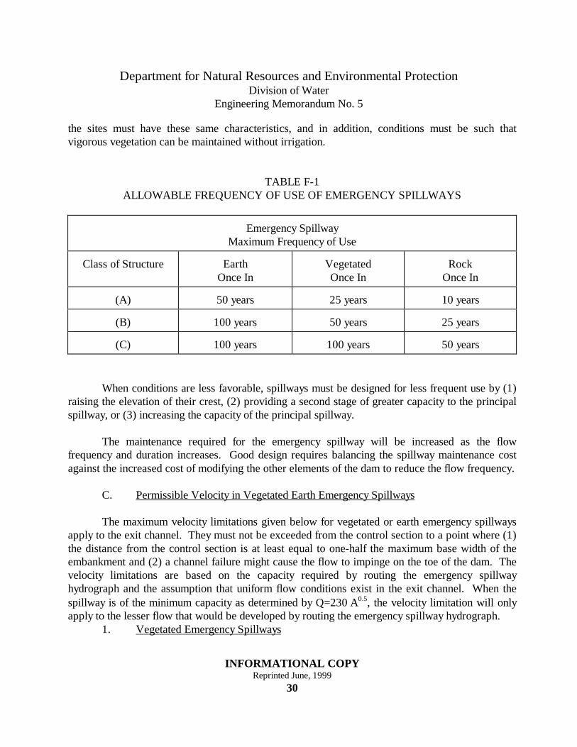
Table F-I gives the permissible frequency of use of earth and vegetated emergencyspillways. For earth spillways, it refers to sites where peak flow of short duration may be expected,and where erosion resistant soils and moderate slopes exist. When vegetated spillways are used,
Department for Natural Resources and Environmental ProtectionDivision of Water
Engineering Memorandum No. 5
INFORMATIONAL COPYReprinted June, 1999
30
the sites must have these same characteristics, and in addition, conditions must be such thatvigorous vegetation can be maintained without irrigation.
TABLE F-1ALLOWABLE FREQUENCY OF USE OF EMERGENCY SPILLWAYS
Emergency SpillwayMaximum Frequency of Use
Class of Structure EarthOnce In
VegetatedOnce In
RockOnce In
(A) 50 years 25 years 10 years
(B) 100 years 50 years 25 years
(C) 100 years 100 years 50 years
When conditions are less favorable, spillways must be designed for less frequent use by (1)raising the elevation of their crest, (2) providing a second stage of greater capacity to the principalspillway, or (3) increasing the capacity of the principal spillway.
The maintenance required for the emergency spillway will be increased as the flowfrequency and duration increases. Good design requires balancing the spillway maintenance costagainst the increased cost of modifying the other elements of the dam to reduce the flow frequency.
C. Permissible Velocity in Vegetated Earth Emergency Spillways
The maximum velocity limitations given below for vegetated or earth emergency spillwaysapply to the exit channel. They must not be exceeded from the control section to a point where (1)the distance from the control section is at least equal to one-half the maximum base width of theembankment and (2) a channel failure might cause the flow to impinge on the toe of the dam. Thevelocity limitations are based on the capacity required by routing the emergency spillwayhydrograph and the assumption that uniform flow conditions exist in the exit channel. When thespillway is of the minimum capacity as determined by Q=230⋅A0.5, the velocity limitation will onlyapply to the lesser flow that would be developed by routing the emergency spillway hydrograph.
1. Vegetated Emergency Spillways

Department for Natural Resources and Environmental ProtectionDivision of Water
Engineering Memorandum No. 5
INFORMATIONAL COPYReprinted June, 1999
31
When the anticipated average use of a vegetated emergency spillway is more frequent thanonce in 50 years, the maximum permissible velocity will be in accordance with the values given inTable F-II. The values may be increased 10 percent when the anticipated average use is not morefrequent than once in 50 years or 25 percent when the anticipated average use is not more thanonce in 100 years.
The values given will be the upper limit for all grasses. Values for grasses or grass mixtureswill be determined by comparison with the values shown, with due consideration given to thegrowth characteristics and density attained in the local area by the species under consideration.
Where bona fide studies or investigations have been made to determine the permissiblevelocity for a specific soil, and site, these values may be used in lieu of those shown in Table F-II.
TABLE F-II
PERMISSIBLE VELOCITIES FOR VEGETATED ARTS SPILLWAYS
Grasses or Grass Mixtures
Soil Type Slope Permissible Velocity
Erosion Resistant 0 - 5%5 - 10%
8.0 fps7.0 fps
Easily Eroded 0 - 5%5 - 10%
6.0 fps5.0 fps
a. Ramp Spillways
The use of ramp spillways is prohibited.
Department for Natural Resources and Environmental ProtectionDivision of Water
Engineering Memorandum No. 5
INFORMATIONAL COPYReprinted June, 1999
32
2. Earth Emergency Spillway
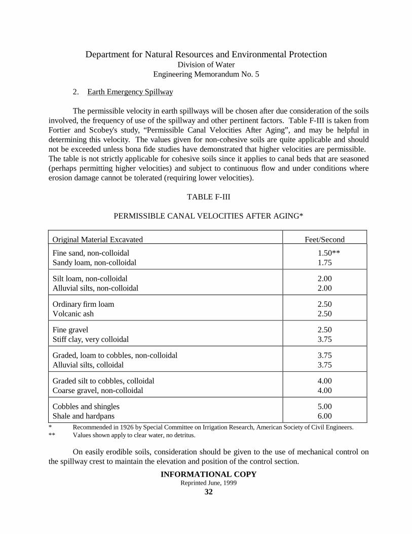
The permissible velocity in earth spillways will be chosen after due consideration of the soilsinvolved, the frequency of use of the spillway and other pertinent factors. Table F-III is taken fromFortier and Scobey's study, “Permissible Canal Velocities After Aging”, and may be helpful indetermining this velocity. The values given for non-cohesive soils are quite applicable and shouldnot be exceeded unless bona fide studies have demonstrated that higher velocities are permissible. The table is not strictly applicable for cohesive soils since it applies to canal beds that are seasoned(perhaps permitting higher velocities) and subject to continuous flow and under conditions whereerosion damage cannot be tolerated (requiring lower velocities).
TABLE F-III
PERMISSIBLE CANAL VELOCITIES AFTER AGING*
Original Material Excavated Feet/Second
Fine sand, non-colloidalSandy loam, non-colloidal
1.50**1.75
Silt loam, non-colloidalAlluvial silts, non-colloidal
2.002.00
Ordinary firm loamVolcanic ash
2.502.50
Fine gravelStiff clay, very colloidal
2.503.75
Graded, loam to cobbles, non-colloidalAlluvial silts, colloidal
3.753.75
Graded silt to cobbles, colloidalCoarse gravel, non-colloidal
4.004.00
Cobbles and shinglesShale and hardpans
5.006.00
* Recommended in 1926 by Special Committee on Irrigation Research, American Society of Civil Engineers.** Values shown apply to clear water, no detritus.
On easily erodible soils, consideration should be given to the use of mechanical control onthe spillway crest to maintain the elevation and position of the control section.
Department for Natural Resources and Environmental ProtectionDivision of Water
Engineering Memorandum No. 5
INFORMATIONAL COPYReprinted June, 1999
33
III. ROCK EMERGENCY SPILLWAYS
Some of the principles used for the layout of earth emergency spillways are applicable torock emergency spillways. Allowable average frequency of use and permissible velocities must beascertained for the specific site based on a knowledge of the hardness, condition, durability, andstructure of the rock formation. An individual appraisal is necessary to determine the properroughness coefficient, “n”. In the absence of a complete investigation and a writtenrecommendation to design the spillway as a rock spillway, the material shall be considered earth. Anote showing the engineer's recommendation and bearing his seal and signature shall be a part ofthe plans. Table F-I gives the permissible frequency of use of rock emergency spillways.
IV. STRUCTURAL EMERGENCY SPILLWAYS
Chutes or drops, when used for emergency spillways, will be designed in accordance withthe principles set forth in SCS National Engineering Handbook, Section 5, "Hydraulics", Section11, "Drop Spillways", and Section 14, "Chute Spillways".
All structural concrete shall be designed by a registered professional engineer and shallconform to the latest accepted design codes.
V. WATER SURFACE PROFILE
The design engineer shall compute a complete water surface profile for both the emergencyspillway storm and freeboard storm, to include an energy grade line, between the upstream anddownstream normal flow depths. This profile shall be a part of the plans and be of such detail as todelineate the required information.
Department for Natural Resources and Environmental ProtectionDivision of Water
Engineering Memorandum No. 5
INFORMATIONAL COPYReprinted June, 1999
34
SECTION G - EARTH EMBANKMENTS
I. HEIGHT
The earth embankment will be high enough to prevent overtopping with the most severe ofthe following conditions: (1) the passage of the freeboard hydrograph or (2) the passage of theemergency spillway hydrograph, plus the necessary freeboard required by the site for frostconditions or wave action.
II. TOP WIDTH
The top width of earth embankments will not be less than the value given by the followingequation:
WH= + 35
5
where H = Height of embankment in feet.W = Minimum top width of embankment in feet.
III. WAVE EROSION PROTECTION
The earth embankment will be riprapped or other wave protection provided over the fullrange in stage between the lowest drawdown elevation and at least a few feet above the full normalpond elevation.

Department for Natural Resources and Environmental ProtectionDivision of Water
Engineering Memorandum No. 5
INFORMATIONAL COPYReprinted June, 1999
35
SECTION H - UTILITIES UNDER EMBANKMENTS
Existing pipelines, cables and conduits of a wide variety of sizes, materials and functions arefrequently encountered at dam sites. These conduits usually are located at shallow depth in floodplain. They constitute a hazard to the safety of the dam and must be (1) relocated away from thesite or (2) reconstructed or modified to provide the durability, strength and flexibility equal in allrespects to the principal spillway designed for the site.
Every reasonable effort should be made to have such conduits, cables, and pipelinesremoved from the site. Most utilities and industries will want their facility removed from the sitefor easy maintenance. Only as a last resort and under the limitations imposed will conduits bepermitted to remain under an earth dam embankment.
Conduits permitted to remain under any part of the embankment below the crest of theemergency spillway must be (1) provided with anti-seep collars when the location of the pipecreates a piping potential, (2) properly articulated on all yielding foundations, (3) encased inconcrete or otherwise treated to insure durability and strength equal to that of the principalspillway, and (4) made absolutely watertight against leakage either into or out of the pipe.
Enclosure of the conduit, cable or pipeline within another conduit which meets therequirements of this section and which is positively sealed at the upstream end to prevent seepageinto the enclosing conduit is acceptable. Such an enclosing conduit will extend the full distancethrough which the conduit being enclosed is beneath the embankment.