Deo-Icing Turbine - Defense Technical Information Centerdtic.mil/dtic/tr/fulltext/u2/a199162.pdf ·...
72
'.....I0 ' Dao-,-, r-&/V Deo-Icing of Aircraft Turbine "FAA Technical EngineC Atlantic City International Airpurt N.J. 08405 M CD H.A. Rosenthal D.O. Nelepovitz H.M. Rockholt Rohr Industries, Inc. Chula Vista, California June 1988 Final Report This document is available to the U.S. public through the National Technical Information' Service, Springfield, Virginia 22161. DTIC S LECTE OCT 0 lei WID US. Depurtment of Transportation H Federal Aviation Administration ____ 7 UIAN D~etIbufna 7Vmmite I
Transcript of Deo-Icing Turbine - Defense Technical Information Centerdtic.mil/dtic/tr/fulltext/u2/a199162.pdf ·...

'.....I0 '
Dao-,-, r-&/V Deo-Icing of Aircraft Turbine"FAA Technical EngineCAtlantic City International AirpurtN.J. 08405
MCD
H.A. RosenthalD.O. NelepovitzH.M. Rockholt
Rohr Industries, Inc.Chula Vista, California
June 1988
Final Report
This document is available to the U.S. publicthrough the National Technical Information'Service, Springfield, Virginia 22161.
DTICS LECTE
OCT 0 lei WIDUS. Depurtment of Transportation HFederal Aviation Administration
____ 7 UIAN
D~etIbufna 7Vmmite I

NOTICE
This doc, ment is disseminated under the sponsorship ofthe Department of Transportation in the interest ofinformation exchange. The United States Governmentassumes no lia blity for the contents or use thereof.
The United States Governement does not endorse productsor manufacturers. Trade or manufacturers' names appearherein solely because they are considered essential tothe object of this report.
Technical Rope"t Documentation Pal*
2.Roag e Govemmassf Acesesion Me. 3. Rkeump....,g C0141011 M..
DOT/FAA/C T-87/37 I________4.~~~S Tifs p. u..il 0.8.
June 1988Doin-cing of Aircraft Turbine Engine Ind'ets; 6. Performin Oepuilaiie.. C440
1. 10. Perforating Organization Report Ne..
H. Rosenthal, D. Nelepovitzi H. Rockholt9. Pderfoatig orlsoliasieft N... sn'd Adduess 0 okUi o TAS
Rohr Industries, Inc. .CotaorGtoMeP.O. Box 0878 DF0-6C05Chula Vista, California 9201 2-0878 13. Tv,.of Roper# eaid Prisod Coereed
12. sponsoring Agaeny Home cnd Add".. FnaU.S. Department of Transportation October 1986-June 1988Federal Aviation Administration Technical Center 14. i;'swn Agencey CedeAtlantic City, International Airport, N.J. 084&05
15. sm"pekaner~y Holes
Flight Safety Research Branch, ACT-340Car;'y Frings, Project Manager/'Contracting Officer's Technical Representative
'This document presents the results of an FAA investigation to determinethe effects of using de-icing,as opposed to anti-icing,in aircraft turbineengine inlets. A literature search was conducted. Ice protection equipmenttechnology was assessed.
This report describes the icing/de-icing process,discusses de-ice systemoperation and performance and ice detector characteristics, and presents amethod for determining the effects of the de-icing process on the turbineengine and its associated induction system.
VAircraft Icing) oueti vial oteUSDe-Icing Systems) I public through the National TechnicalIce Detectors) Information Service, Springfield, 22161niAnti-icing ,, s.w( IV.i.. ei u.)f2.N.c .. 22161is
Unclassified Unclassified
Form DOT F 1700.7 (8-72) Reproodwetios of coplsIeeio page ejth*442104

PI P'ACR
Major contributors to this study were:
-Mr. Steve Clark, Ms. Sue Downs, Dr. Graham Lewis and Mr. IanStewart--Rolls-Roycep plc;
-- Dr. Glen Zumwalt--Wichita State University;-- Mr. Al Weaver--Pratt & Whitney, Inc.; and- Dr. Bonnie Gransow-HRohr Industries, Inc. (writing services)
[email protected] Foro
DTIC TAB 1[Unannounced 0Justitioation
Distribut ion/
AvallS1ability Codes
/~Avai and/orDist Speolal

--------
USIIR OF OONUYS
section
EXECUTIVE SUMMARY ..................................... ... .............. vi
INTRODUCTION ............................................................. 1OB3JECTIVb ....... .. ... ... ............... . 1BACKGROUND ................................................. ... ....... 1
DR-ICINQ THICNOLOGY STATUS ....... ...... ... . ..... ... o.. ................ 2OVERVIEW ......................................... o................... 2
ANTI-ICING ................................... .......- , ........ s.... 5DE-ICING . . ............... I..............,,. .......... ......... ....... 8
ICE DETECTION SYSTEMS . . ... . .. & ... .. . .. .. o . . .. ................ . .. 15
ICE ACCRETION AND DR-ICING EVALUATION ................................. 20PHYSICAL PROPERTIES OF ICE .......................................... 20COMPUTER ANALYSIS OF ICING AND DR-ICING ............................ 22WORST-CASE DR-ICING CONDITIONS .................................... 26RNGINF MANUFACTURER'S ICING EXPERIENCE .......................... ... 27
SAFETY REQUIREMNTS SUBSTANTIATION ..................... ...... s .... 29ALLOWABLE ICE ACCURTION ............ &............................... 29ALLOABLE ICE INGESTION ....... ................... ... o ... .. ......... 29ICE IMPACT EFFECTS ON ENGINE COIMONENTS ............................ 30GENEltAL STRUCTURAL ANALYSIS OF IMPACT DYNAMICS ..................... 40SAFETY ISSUES OF DR-ICING SYSTEMS ................................... 40SAFETY PRECAUTIONS APPLIED TO DR-ICING SYSTEM ..................... 42
CONCLUS IONS ............................. o.................. ............. 47
REFERENCES. .............. 48
APPENDIX A - ICING CONDITIONS .................. . ....... ........ A-1
APPENDIX B - RIDI TESTING ........................................ ..... B-1
APPENDIX C - DISTRIBUTION LIST ................. o .......... , ...... C-1
iii

LIST OF ILLUAiTIO
Figure Lm
DR-ICING TECHNOLOGY STATUS2-1 Schematic of ]igine/Nacelle Installation ......................... 22-2 Anti-Icing Channeling System .................................... 52-3 Combination of Hot Air, Oil and Electrical Ice Protection
in L Turbojet Installation ................ ..................... 62-4 Turboprop Inertial Particle Seperator ............................ 72-5 Schematic Cross-Section of a Pneumatic Boot De-Icer
(Inflated) as Installed on an Engine Inlet ..................... 92-6 Electrical Resistance Heating of Engine Inlet ................... 102-7 De-Icing Cycles of Electrical Resistance Heater ................. 112-8 Cross-Section Through Inlet Leading Edge Showing
Bulkhead-Mounted RIDI Coil ........................ ....... 122-9 Cross-Section Through 311I Coil Showing Coil's Current and
Magnetic Field and Resulting Eddy Currents in Skin ............ 132-10 Electromagnetic Expulsive De-Icing Boot Shown in
Expanded State ................................................ 14
2-11 Arrangement of Ribbon Conductors in ElectromagneticExpulsive De-Icing Boot .................................. 14
2-12 Piezoelectric Diaphragm Ice Detector Shown Installedan Aircraft Surface and Two Variations Shown Nextto a Quarter for Size Reference ............................... 17
2-13 Piezoelectric Film Ice Detection/De-Icing System(General Arrangement) ...................................... 18
2-14 Ultrasonic Pulse-Echo Ice Detector Concept ...................... 19
ICE ACCRETION AND DR-ICING EVALUATION3-1 Four-Point Bend Loading ......................................... 203-2 Rheological Model for Dynamic Loading Tests of Ice
Strength ................................... ...... 213-3 Icing/D.-Icing Analysis Flow Chart ............................. 223-4 Surface Panel Modeling of a Wing, Pylon and Nacelle
Using the VSAERO Computer Code ......... .... ...... ............. 243-5 Ice Fragment Cross-Sectional Area Presented to Airstream
During Tumbling .... .. . ........... * ..................... 0 .00... 26
SAFETY REQUIR NTS SUBSTAN!IATION4-1 Initial Path of Ice Shed from Engine Inlet Leading Sdge ......... 314-2 Relationship Between Kinetic Energy Normal to Blade
Leading Edge and Fan Blade Damage ............................. 334-3 Velocity Triangles of Ice Impact at Fan Blade Leading Edge ...... 354-4 Typical Profile of Ice Velocity Increase with Engine
Inlet Lenigth .................................................. 36
4-5 Variation of Vcrit with Ice Mass ard Non-DimensionalFan Blade Radius (Narrow-Cord Faii Blade) ...................... 37
iv

4-6 Variation of V .it with Ice hass and Non-DimensionalFan Blade Radium (Wide-Cord Fan Blade) ........................ 37
4-7 Curvature of Ice Fragment Impacting Fan Blade ................... 394-8 Phases of Ice Impact ................................... .......... 41
CONCLUSIONS5-1 Inlet De-Icing System Certification Process ..................... 46
LIST Of TA•LfS
Table PaLe
DR-ICING TEChNOLOGY STATUS2-1 Respondees to De-Icing Technology Status Questionnaire ........... 32-2 Xce Protection System Currently Used on Aircraft ................ 42-3 Aircraft Equipped with Inlet Ice Detection Systems-
All Have Vibrational-Type Sensors ............................. 16
V

DZOUTrVU SUNKIARY
Turbine-engined aircraft are faced with potential problems frrm the buildupof ice on the inlet ducts of the engines. Such icing could restrict theairflow through the engine, affect engine performance and possibly causeengine malfunction. Furthermore, accreted ice, if dislodged, could enterthe engine and seriously damage it.
Turbine-engined aircraft traditionally have used anti-iced air inlets forflight into known icing conditions. These systems use large amounts ofengine compressor blood air or electricity, which may result in an attendantfuel consumption penalty. This penalty may be minimised if de-iced, ratherthan anti-iced inlets are used.
Advances in do-icing technology have led the aircraft industry to considerthat inlets on some new engines be do-iced, rather than anti-iced. For thisreason, the Federal Aviation Administraton Technical Center is examiningde-icing technology, the impact of de-icing system operation on the turbineengine, and the potential for increased use of de-icing systems on moreaircraft.
This report details the results of an investigation into do-icing systems.The conclusiokin are:
-Due to energy considerations, a demand to use do-iced inlets is ex-pected to increase in the mid-1990s.
-Three new de-icing systems--electromagnetic impulse, electromagneticexpulsive and pneumatic impulse have been shown to be feasible.
-Do-icing systems must be evaluated to determine the thickness andshape of ice they cause to be shed.
-Damage tolerance levels can be established and included in the speci-fications for the design of do-icing systems.
vi

DITRODUOTION
Recent research into new aircraft ice protection technologies offers thepossibility that do-izing systems may be used on aircraft turbine engineinlets that would otherwise be equipped with anti-icing systems. The objec-tive of this project was to investigate the de-icing technology available,and that being developed and to determine the effects of these de-icing syn-teme on the engines.
To evaluate the effects of ds-icing systems on the engines, this studyaimed to: 1) determine the amount of inlet ice that accreten between de-icing cycles; 2) identify analytical and/or empirical methods for determin-ing the sise, amount and path of ice shed during de-icing of an inlet lip;and 3) determine what type of engine or inlet damage can be caused by iceshed from the inlet.
BACKGROUND.Anti-icing systems prevent ice from forming on a surface, whereas do-icingsystems dislodge ice that has been allowed to form. One possible advants&oof do-icing over anti-icing in the potential for reduced specific fuel con-sumption (SWC). To prevent the formation of ice, an anti-icing system mustbe continually operated in icing conditions and, as a result, requires alarge energy input. This energy is derived by consuming fuel, thereby cre-ating a significant SFC penalty. This S7C penalty is expected to be evenmore severe in the next generation of turbine engines, which, because oftheir high-bypass design, will have a decreased airflow to the core engineand, in turn, less hot compressor bleed air available for heating aircraftsurfaces. A do-icing system, on the other hand, uses much leas energybecause the system need not be operated continually in icing conditions, butonly at intervals, just enough to keep ice from building up beyond tolerablelevels.
A major concern when applying do-icing systems to turbine engine inlets isthe effect of ice shed into the engine. Shed ice could isapact variousengine components such an fan blades, guide vanes, acoustic panhla, etc.Ice accreted on inlet surfaces between do-icing cycles may also cause someairflow disruption, thereby affecting engine performance. These concernsare addressed and recommendations are made to minimise these effcts.
Some aircraft with de-icing systems are equipped with particle separatorcto reduce or eliminate engine ingestion of ice shed from the inlet. Thisreport addresses do-icing both with and without particle separators.
1

D3-ICI/N TUOSOLOGY SIAUB8
This section provides a summary of aircraft ice protection, comparing evap-orative anti-icing, "running wet" anti-icing, and do-iciuig. It then detailsthe current status of aircraft do-icing technology, both that in service onaircraft and that in development. Material covered in this section wasgathered from survey questionnaires sent to airframe, engine, ice detectionand de-icing system manufacturers. RespG° Jenta to the survey awe listed inTable 2-1. Table 2-2 relates the various types of ice protection to theengines on which the: are used.
The engine/nmcelle installation in Figure 2-1 illustrates the relaLUornhipbetween the forward parts of the engine and the lip of the engine inlet ductwhere ice accretion can occur during flight through icing conditions. Inorder to avoid intolerable amount. of inlet ice buildup, some type of iceprotection is used. Completely evapomtive anti-icing causes water imping-ing on the engine inlet lip to evaporate, thereby preventinS formation ofice. "Running wet" anti-icing aystems do not necessarily supply enough heatto cause evaporation of all impinging water, but are able to kaep the waterabove the freesing point. In some of these systems the water may run backto unheated regions and freese there.
Edge
Fan Guide WPnes
Figure 2-1. Schematic of Engine/Nacelle InsfAllIation-This schematic illustrates the spatialrelationships between the Inlet leading edge, where ice accretion can occur, andcomponents of the enginelinlet that might be subject to damage from ice dislodgedfrom the inIes leading edge.
2

Table 2-1. Respond*.* to Do-Icing Technology Status Questlonnamir
AIRFRAME MANUFACTURERS
Avions Marcel Dessault-Breguet Aviation (France)Beech Aircraft Corp. (United States)Boeing Commercial Airplane Co. (United States)British Aerospace plc (Great Britain)Cessna Aircraft Co, (United States)DeHavilland Canada, Inc. (Canada)Douglas Aircraft Co. (United States)Fairchild Aircraft Corp. (United States)Lockheed-California Co. (United States)
ENGINE MANUFACTURERS
Avco Lycoming Textron (United States)Pratt & Whitney Canada (Canada)Rolls-Royce plc (Great Britain)
DE-ICING SYSTEM MANUFACTURERS
AEG-Aktlengesellschaft,Space & New Technologies Div. (Germany)
BF Goodrich (United States)Innovative Dynamics (United States)Lucas Aerospace Ltd. (Great Britain)Simmonds-Precison (United States)TKS Aircraft De-Icing Ltd. (Great Britain)
ICE DETECTOR MANUFACTURERS
Datproducts N.E. (United States)Lucas Aerospace Ltd. (Great Britain)Rosemcunt, Inc, (United States)Simmonds-Precision (United States)Vibro-meter Corp. (United States)
3

Table 2-2. lee Protection Systems Currently Used on Aircraft*
lee Prasle n Syst m BY ngin LAmmA Company
Antl-icing.- CF=0 Turbolan Falcons 20 Avian* Msrc4A DassaultNocmrso air TPIEMSl2 Airboln Falco W0OO Aviona Marcel Dassault
TFE731-3 tirbolan Falcon 50 Avlons Maircel DsasaauATF34A Turbolan Falcon 200 Avian* Marcel DassaultATF3.6 1b.bolan HU25A Aviana Maemel DassaultTFE731-4A Turbolan Falcon 900 Avion@ Marcel DassaultJ73D 1Ubots 797 Boeing.1110 )Irbotkn 727 Boeing.1750 TUrbolan 737 BoeingJTID/CF6I1B21-524 Turbofan 747 BoeingAB2ii-535PW2037 Tuarbolan 757 BoeingJ111DICIF11 Tubolan 76P BoeingATF502 TUrbolen She 146 British AerosaceTIFE7"1 Turboln UO0 CessnaTPE3S11-54406S TIrbAb 441 CessnCr6144204 W~~ 014c0 wBufao DeHavllland CanadaCFMSS Vbbolan 0C4170 Douglas Aircraft CO.01110417 Awarbob MO-10 Douglas Aircraft CQ\.T1110.219 Turboahn MD-43 Douglas Aircraft Co.CF.640.2 Turbola 100-10 Douglas Aircraft Co.CFG-50-C2 Turbolan OC-10-30 Douglas Aircraft Co.CF84"C Tubofan DC-10-10 Douglas Aircraft Co..1110-2W Turbofan 0C-10.40 Douglas Aircraft Co.A ~Ii babolan L-1011 LockheedTF-34 Turbofan S-3 Lockheed
Anti-icing- JTISD-1, O-IA, D-1B urbajet 500/501 CessnaHot compressor air and JT15D-4 lTurbojet 5001551 Cessnaelectric heating_____________
Ano-cingHot compressor air and hot oil JTISD48 T~roe S550 CWssna
AntI-cin- PTIA-21 Turboprop King Air Model COMG Beech Aircraft Corp.MCI edsuM ot ga.PI-42 Turboprop King Air Modal 200 Beech Aircraft Corp.inerma pwartceseparator and PUhA450A Turboprop King Ar Mode 1-300 Beech Aircraft Corp,%I~ irea protect'v scree PMU468 Turboprop Modal 1900 Commuteor Beech Aircraft Corp.
PMU-42 Turboprop C12 Military Seri"s Beech Aircraft Corp.______________PY.GA-25 Taboprop r34C (Singe Engine) Beech Aircraft Corp.
Anti-icing.-Hot schaust gas and PTIA-112 Turboprop 406425 CessnaInertial pairticle sepraorw______ _______
rAMl*lcng.- Pr6A-45 Turboprop Mtom lIRA. SA22-PC FairchildHot auihaust gas P"hA-60 Turboprop Merin IVO SAW2-PT Fairchild
PlbA4O0 Turoprop Merln iliaD SAW.TP Fairchild
De- c:ing.- TPE331-3 TUrboprp Meto 11, 11A. SA226TC FairchildHot compressor air TPE331-11 Turboprop Metro IlN SA22-AC Fairchild
TPE331-3 Urboprop Merln IV, 1141k SA226-AT FairchildTPREU11-11 Turboprop MeM rli , SAW-AT FairchildTPEMII.11 Turboprop Expe&Ka. SAW-Ar FairchildTPES3TI- Turboprop Merlin IlN. SA=6-T FairchildTPE3313 Turboprop Marl4 AflA, SA226-T FairchildTPI3SI-10 Turboprop Merlin MRl SA226-T(S) FlairchildTPE3S1-10 Turboprop Marl INC11 SAW2-Tr FairchildPTSA4O Turboprop Marlin IND. SAW2-TP Fairchild
Do-irng.-Electric heating and PU-27 Turboprop DMC4 Twinn Otter DeN lavilland Canadaineria particle separator___ _____________
De-cicrg-- PTIA-0 Turboprop DHC-7 DeHavilland CanadaPneumatic boat and PWI20 Turboprop DHC-6 De~avilland CanadaInertial particle separplor PwIIS Turboprop EMB-120 Embraer
IPTIBA-45 Turb~om M2941 FralcesInertial Particle Separator PTOA-114 Tu.rboprop 206 Cessna
*This table was compiled from the survey responses anid, therefore, is by no means complete, inpart, because some manufacturers opted not to disclose proprietary information.
4

In contrast to an anti-icing system, a do-icing system is designed to removeice that has been allowed to accumulate to some level predetermined to betolerable to the aircraft mad engine. TLereforet do-icing expends much lesenergy than anti-icing because the system in activated only at regularintervals, with ice buildup allowed between do-icing cy.-lea. The timing ofthe cycles is a function of the particular system being used and the icingconditions being faced.
ANTI-ICMG.Since the advent of the gas turbine engine, hot blood air from the engine'shigh-pressure compressor has been available as a heat source for anti-icingengine inlets. This source can supply enough heat to prevent ice formationthroughout most icing conditions for large turbine engine/nacelle notala-tiona (Table 2-2).
Three different systems for channeling and directing hot anti-icing airover the backside of the engine inlet leading edge have been developed(Fig. 2-2). In the double-wall system, hot air circulates through a ductformed between the bulkhead and an inner leading edge w-ai and flows throughholes In the inner wall to heat the outer wall of the inlet, leading edge
A"AI
UPA. SDMM" SysU
Fg -A t-
IIwi
F. igure 2-2. SsAnt-cnmhnnln Vt
5

(Fig. 2-20). The piccolo tube system is a modification of the double-wall system in which the inner leading edge wall is omitted and hot aircirculates through a tube that extends around the circumference of theinlet. Air exits from holes in the tube to heat the inlet leading edge(Fig. 2-2B). The swirl system is a further simplification in which thecircumferential piccolo tube is omitted su that hot air swirls around thecircumference of the inlet leading edge in the entire space forward of thebulkhead (Fig. 2-2C).
Very few turboshaft engine installations, such asn turboprops, use enginecompressor air for inlet anti-icing. Instead# alternative heat sources suchas exhaust gas, hot engine oil, electrothermal heater mate, or a combinationof these sources are used (Fig. 2-3). In extreme Icing conditions, some ofthe water may run back to unheated regions of the inlet and freese there.This condition I. called "running wet." Running-wet systems use low amountsof energy compared to completely evaporative anti-icing systems. This itwhy running-wet systems are preferred in engines that cannot afford toexpend a lot of energy on ice protection.
Inlet Strut
" ooHot AlIr Valve
Guide 6
i [ Fuel Heater
Pump .
0 Hot Air
Oil Cooler Electrical
Figure 2-3. Combinationofl Hot Air, Oil and Electrical Ice Protection In a lUrbine Installation
6

In some running-wet systemg water channels are designed into the inlet'ssurface to divert water overboard or away from the engine. This type ofdiversion keeps the water from collecting on and freezsing to the inlet lead-Ing edge. Not all running-wet systems require water channels; the designof some engines incorporates inlet air bypass ducts that channel a certainportion of the inlet air away from the engine. These bypass ducts can bemodified to also serve as particle separators that divert foreign objectssuch as birds and ice away from the engine (PIg. 2-4). These same bypassducts can also help channel water away from the Inlet's leading edge.
•,Spinner .Actuator
for Vanes I and 2 i f n dective
Vans #1 -lxVane #2
ýFixd Vanes Overboard
Position of Vanes and Airflow for Icing Conditions
Propeller Compressori•Spinner Ac•tUOv 1 uator
Air nletAir Bypass
f,.• • Channel
SVane #2
Vane #1 Fixed Vanes
Position of Vanes and Airflow for Non-icing Conditions
Figure 2-4. Turboprop Inlertial Particle Separotor--During icing conditions some airflow is di-
verted downward away from engine, carrying the heavier-than-air ice particles with it.
7

In aircraft where water running back and freezing on unheated regions of theinlet create@ an unacceptable rtk. the same energy sources used for anti-icing water-impingement areas, euch as the Inlet leading edge, can be usedfor do-icing the areas further aft where water collects and freezes. Thisice protection technique is another way to reduce energy consumption com-pared to anti-icing all regions.
Some propeller-driven aircraft still use a system consisting of air heatedby an exhaust manifold for anti-icing.
DU-IMAL6GEngine inlet do-icing systems have been developed for aircraft in whichenergy consumption must be kept to a minimum. This section describes thedo-icing systems currently In use (electrothermal mats ai,,d pnuematic boots)and those under development (pneumatic impulse, piezoelectric vibration,electro-expulsive and electromagnetic impulse do-icing). Of the latter,electromagnetic de-Icing (SIDI) appears to be the most mature at this timedue to the relatively high level of research and development associated withit. Research on SIDI, in which Bohr and Rolls-Royce have participatedextensively, In detailed in Appendix B.
For many 1e-icing applications, ice ingestion is not tolerable and particleseparators have become an integral part of these de-icing systems. In thosecases in which particle separators are not used, engine tolerance to iceingestion must be analysed and assurances made that ice ingestion does notadversely affect safe engine operation.
A related emerging technology-that of improved ice detectors-is antici-pated to advance effective and safe de-icing operations. Current researchis aimed at developing ice sensors as part of an automated ice detection andde-icing actuator system.
PHN W1TIO BOOTS. Pneumatic boots, currently the most common mechanical sys-tems used for de-icing, ars the most widely used means of wing do-icing forgeneral aviation aircraft. They are also used for engine inlet do-icing inseveral turboprop commuter aircraft (Table 2-2).
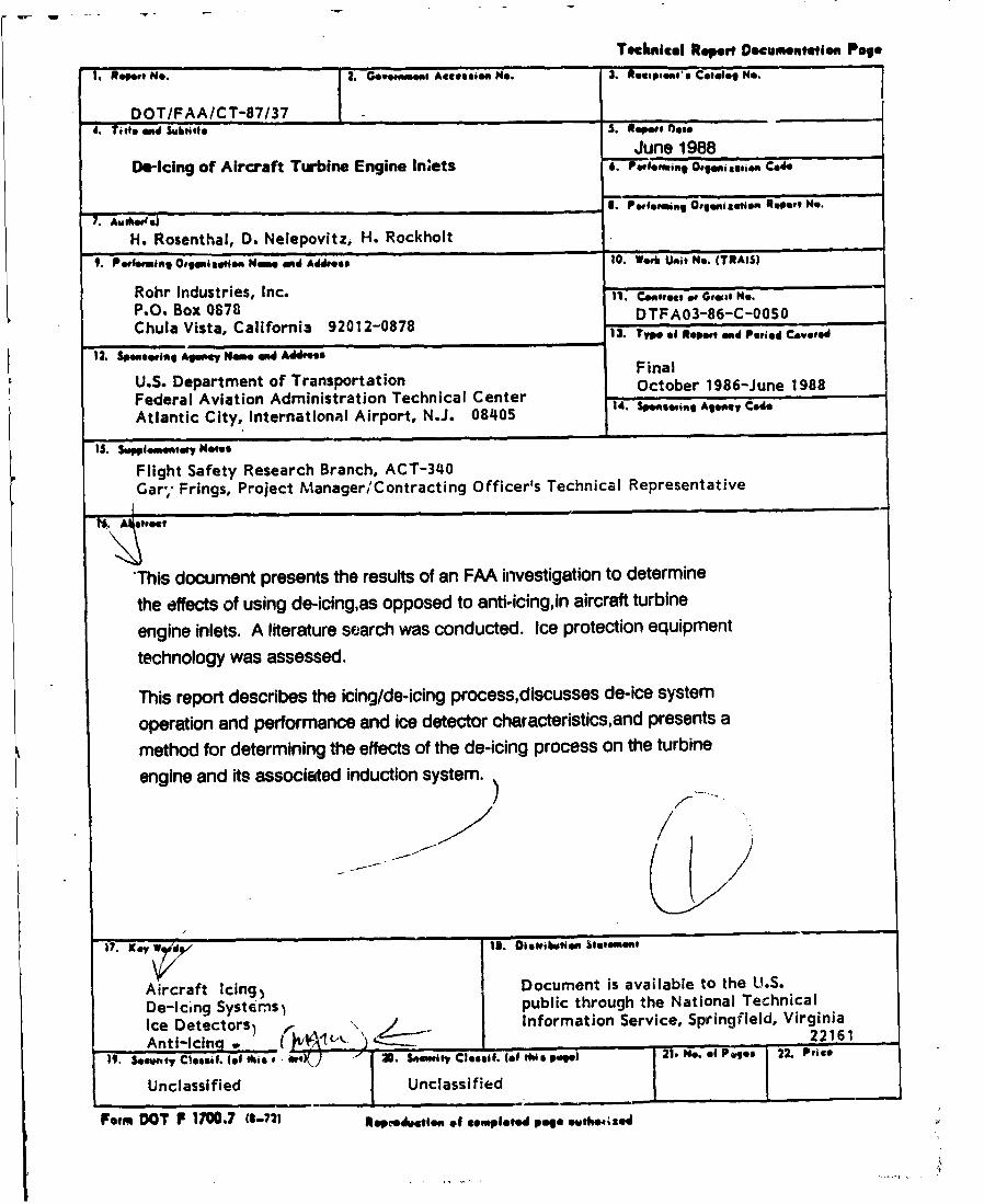
A pneunatic boot consists of an inflatable bladder bonded to the surfacethat requires ice protection (Fig. 2-5 and Ref. 2-1). During operation,pressurized air is forced into the bladder causing it to expand with a sur-face deflection rate of approximately 0.35 in/sec. This expansion breaksthe ice/ bladder bond and fractures accreted Ice into small pieces. To pro-note the breaking of the ice/bladder bond, an Ice adhesion reduction agentis often applied to the bladders before each flight.
Due to the deformation imparted to the wing airfoil or inlet leading edgeduring the activated phase of a do-icing cycle, pneumatic boots are limitedto low- and mid-velocity applications (up to Mach 0.5). The pneumatic bootusually requires a vacuum system to keep the bladders flat when not inuse, thereby preventing an irregular aerodynamic surface between de-icinginflations.
8
..•...•. • •Bladder8
Skin of •
EngineIne
Figure 2-5. Schematic Cross-Section of a Pneumatic Boot De-icer (Inflated) as Installed onan Engine Inlet
As with many do-icing mystema, there is a minimum ice thickness at whichpneumatic boots become effective. This is 0.125 inch for current pneumaticboots, but the ice must be a contiguous accretion. Pneumatic boots areoptimally effective over sn ice thickness range of one-eighth to one-quarterinch. As with most mechanical do-icing mystems, rime Ice (defined in Appen-dix A) on the upper and lower airfoil or on the inlet surface will remainattached longer than leading edge ice. Rime ice accretes slowly and canusually be shed before it becomes excessively large and create@ an aero-dynamic problem.
The size of ice fragmonts shed by a pneumaUc boot is determined by theon/off cycle time and icing conditions. Testing and previous experiencewith similar engines are taken into consideration and used in evaluating anew application. Many pneumatic boot systems are used in conjuncUon withinertial particle separators to minimise Ice ingestion by the engine.Whether or not a particle separator is required depends on the ice damagetolerance of the engine.
Improvements in the means for retarding erosion of pneumatic boots haveresulted in a significant Increase in intervals between boot replacements-from 10,000 flight hours in 1950 to 20,000 flight hours in 1980.
Many turboprop aircraft use freezing point depressant (FPD) fluids in con-junction with pneumatic boots for de-icing. These can be applied externallyto propeller blades and wings, either manually during ground servicing or inflight by transpiring the FPD through porous external surfaces. In-flighttranspiration of FPD is not used, however, in turboprop aircraft whereengine bleed air im- used to supply cabin air. This limitation avoids thepossibility of accidentally contaminating bleed air with FPD which couldproduce harmful vapors in the cabin.
9

RLUOTRIC NZATRU. Blectrothermal de-icing systems are typically umed inaircraft where hot-air anti-Jcing systems are not feasible. Hot air or hotfluid systems have inherently slow thermal responses and may 'Wherefore beunsuitable for de-icing. Blectrical resistance heaters, however, can pro-vide the rapid heating needed. De-icing cycles can be timed so that littleor no runback occurs between heat-on periods.
Electric&! resistance heaters consist of mats of strip conductors embeddedIn surfaces requiring ice protection by sandwiching the mats between layersof neoprene or glass cloth impregnated with epoxy resin (Fig. 2-6). Themats are protected against water erosion, with a special polyurethane-basedcoating. On turboprop engines, the engine inlet leading edge, the propellerblades and the propeller spinner may use electrical heating for ice protec-tion. Electrical power Is supplied by a generator, and to keep the size andweight of the generator to a minimum, the de-icing electrical loads arecycled between the differert ice-protected regions.
During operation of the de-icing system, a thin strip of the leading edge ofthe inlet is continuously heated to prevent an ice cap from forming on itand to help limit the amount of ice that forms on the areas further aft thatare intermittently heated (Fig. 2-6.)
The cycle timing of electrical resistance de-icing systems is adjusted to aschedule predetermined to provide sufficient ice protection for the partic-ular icing conditions encountered. A two-speed cycling system is often
SGlass Ckoth Layerm
•. ,InleS//Leading
Y Electrical
Elcrca etiAt Junction Box
Continuously Heated Elements
Intermittently Heated Elements
Figure 2-6. Electrical Resistance Heating of Engine Inlet
10

usod-& short-duration cycle at, higher air temperatures whore the water con-centration is usually greater and a long duration cycle in the lower temper-ature range (Fig. 2-7). The power and timing of the de-icing cycle requiredfor effective do-icing can be estimated, based on analytical methods (Ret.2-2) and comparisons with other proven do-icing systemap but verification ofde-icing effectiveness in checked in icing wind tunnel testing.
The electrical heater type of de-icing system is also used in conjunctionwith a foreign object bypass duct to prevent most shed ice from beingingested into the engine.
PIDUMAC IMPULSEIL A modification of the pneumatic boot system--the pneu-m-tic impulse do-icing system-is currently under development. This systemworks essentially the same as the pneumatic boot system, however, insteadof expanding slowly, th,, inflatable bladders are expanded rapidly by high-pressure pulses of air. The surface movement is approximately 0.1 inch in0.1 second. Because of the shortened times for bladder inflation and, thus,the minimal deformation of airfoil surfaces, this system can be operated onhigher speed aircraft than the pneumatic boots. The system currently beingdeveloped has a thin titanium sheath covering the flexible boot to enhancedurability and reduce erosion.
ULTM A MC IM]PULS3 DIF-ICIG (XIDI). Electromagnetic impulse do-icingrequires no external additions to the aircraft skin. An electric currentpulse generated from a capacitor is transmitted through spirally wound,flattened coils made L; om ribbon wire. The coils are rigidly supportedizmide the aircraft skin but are separated from it by a gap of approximately0.1 inch (2.5 mm) (Fig. 2-8). Various coil-mounting configurations aredescribed in Appendix B.
FAS Cying SpeedOne Cycle
MaxEnieProp Engine
INOei and Inlet
j~Spinneir
Slow Cycing SpeedOne Cycle,
Max
InNK, and InletSpnner
Time
Figure2-7. De-Icing Cycles of Electrical Resistance Heater
11

S• Bulkhead
- Fiberglas
Figure 2-8. Cross-sectlon Through Inlet Leading Edge Showing Bulkhead-Mounted EIDICoil
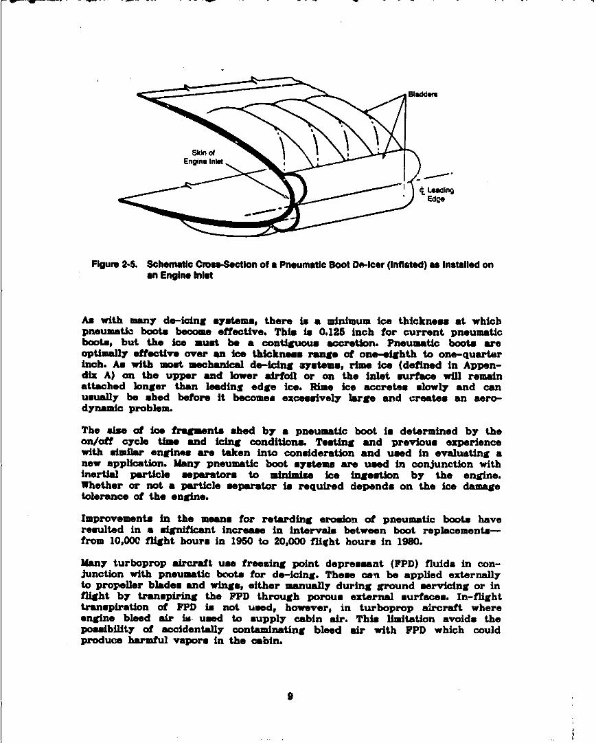
The BIDI coil current produces a magnetic field, which induces an eddy cur-rent in the thin metal skin (Pig. 2-9). The two currents' fields repel eachother. The resultant force cause• a low-diuplacement, high-accelerationfovement (0.01 inch per 0.001 second) of the skin adiacent to the coil.
This movement shatter@ the ice and breaks the bond between ice and skin; theice is then swept away from the surface by aerodynamic forces. This crack/debond/dislodge process usually sequires two impulses separated by therecharge time of the capacitators, typically three or four seconds. Thepower supply Is then electrically switched to a coil (or coils) at anotherlocation on the engine inlet and the process it repeated. The system cyclesback to the original coils before an appreciable amount of ice in accreted.
Oonnecting wires from capacitor to DIDI coil must be low in resistance andinductance to achieve the fastest impulse response. If the inlet skinthickness is less than the minimum required for adeq•a.te conductance of theinduced eddy currents, metallic doublers are used to increase conductance(Fig. 2-8). These doublers are usually aluminum discs, slightly larger thanthe coils, bonded to the skin between the skin and the coil Mletallicdoublers are a necessity for non-metallic composite skins.
The energy required for electromagnetic impulse do-icing of an area in about1 percent of that required for thermal anti-icing of an equivalent area. Toachieve this, BIDI design must carefully match the clectrical pulse width tothe electrical and structural responess of the leading edge. The designprocedure is summarised in Ref. 2-3 and explained in detail in Ref. 2-4.
BIDI is currently under development and is being considered f.,r some nowangine ice protection designs. Tests so far performed have demonstratedthat BIDI is an effective do-icing systemo These tests and their resultsare summarised in Appendix B.
12
FEddy Currents
Skin
CNI
Figure 2-9. Cross-section Thrcugh EIDI Call Showing Coil's Current and Magnetic Field andResulting Eddy Currents in Skin-Currents flow in a loop in and out of paper planefrom "."'to "+"
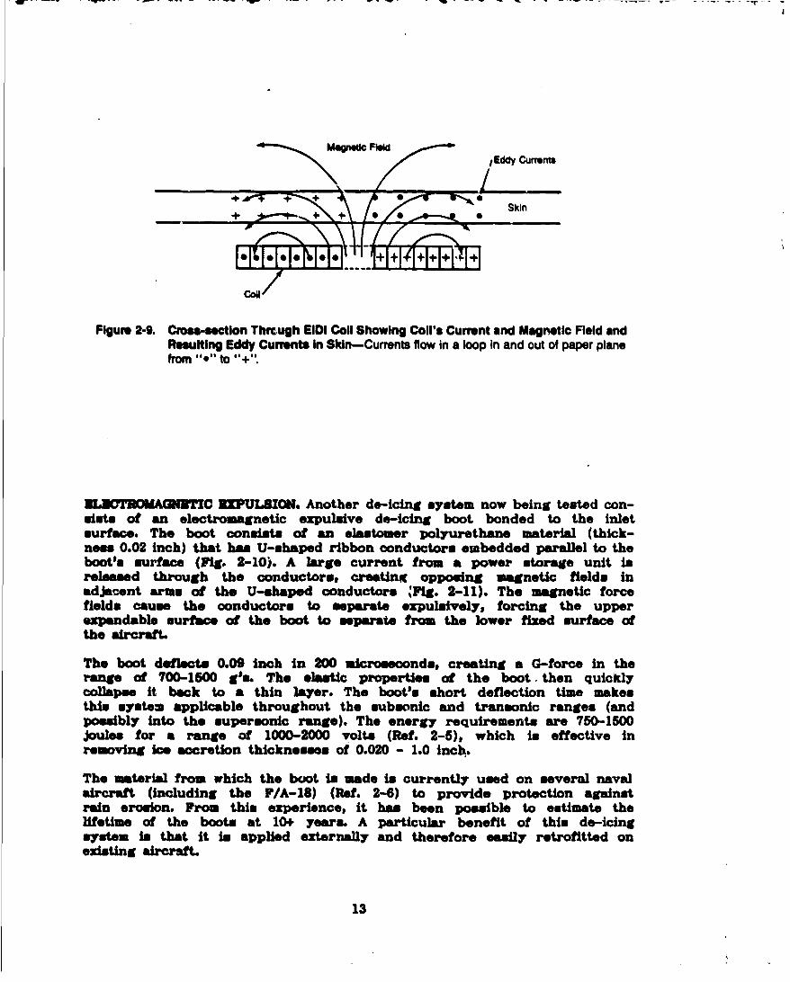
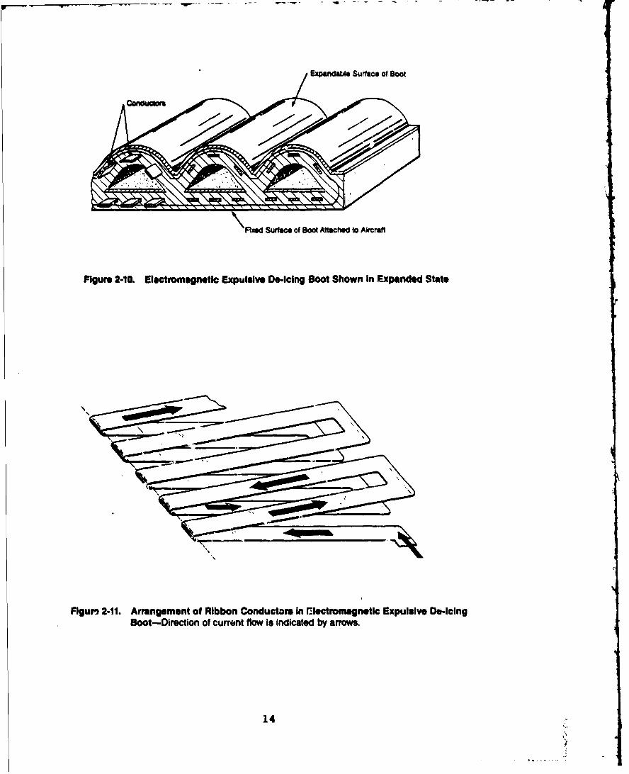
LUOTD7OMAGNIC CP =0111ON. Another de-icing system now being tested con-mists of an electromagnetic expulsive de-icing boot bonded to the inlet
surface. The boot consists of an elastomer polyurethane material (thick-ness 0.02 inch) that has U-shaped ribbon conductors embedded parallel to theboot's surface (Fig. 2-10). A large current from a power storage unit isreleased through the conductors, creating opposing magnetic fields inadjacent arms of the U-shaped conductors MFig. 2-11). The magnetic forcefields cause the conductors to separate expulsively, forcing the upperexpandable surface of the boot to separate from the lower fixed surface ofthe aircraft.
The boot deflects 0.09 inch in 200 microseconds, creating a G-force in therange of 700-1500 g's. The elastic properties of the boot. then quicklycollapse it back to a thin layer. The boot's short deflection time makesthis system applicable throughout the subsonic and transonic ranges (andpossibly into the supersonic range). The energy requirements are 750-1500joules for a range of 1000-2000 volts (Ref. 2-5), which is effective inremoving ice accretion thicknesses of 0.020 - 1.0 inch.
The material from which the boot is made is currently used on several navalaircraft (including the F/A-18) (Ref. 2-6) to provide protection againstrain erosion. From this experience, it has been possible to estimate thelifetime of the boots at 10+ years. A particular benefit of this do-icingsystem is that it is applied externally and therefore easily retrofitted onexisting aircraft.
13
Expanda"l Surface of Boot
Fixed Surface of soot Afttched to Aircraft
Figure 2-10. Electromagnetic Expuluive Do-Icing Boot Shown In Expanded State
.............
Flgur, 2-11. Arrangement of Ribbon Conductors In Electromagnetic Expulsive Do-icingBoot-Direction of current flow is Indicated by arrows.
14

- - - - _• - . . .. .. -• . . . . . . r - . . . . . .
H2LICOPrTRS. Most helicopters do not have an ice removal system that iseffective throughout the FAR envelope of icing conditioa. As of this time,no U.S.-manufactured civilian helicopter@ are certified for flight in icingconditions. Rowever, electrothermally heated rotor@ in conjunction withicing rate sensors permit the operation of wsme military helicopters inlight icing conditions by providing protection for a limited set of icingconditions along with information that help@ the helicopter pilot Judge theduration of safe flight.
For helicopters, the duration of flight in icing conditions in limited bythe icing of the hub and rotor blades; therefore, a good portion of icingresearch focuses on the rotor and hub, rather than on engine inlet iceprotection. The severe limitations on helicopter flights into icing condi-tions have been a driving force behind current efforts to develop new iceprotection technologies, such as ice phobic coatings, mechanical vibrators,microwave emittora, SIDI systems and pneumatic impulse systems Theme tech-nologies, in some cases, maw be adaptable to fixed-wing aircraft am well.
A method of engine inlet ice protection unique to helicoptors in the exter-nally mounted heated inlet screen. Electrical resistance heating of thescreen keeps large ice accretions from forming, thereby allowing only verysmall ice fragments (and resulting water) to pass into the engine inlet.The small ice fragments are further removed by an internal particle sepa-rator. These systems typically are not intended for long-duration operationor heavy icing conditions. Other means of helicopter ice protection now inuse include electrothermal mat. and experimental pneumatic boots for rotorisystems (Ref. 2-7).
ICE DETBCTION SYSTEMS.In uircraft without ice detector@, air crews are alerted to icing conditionseither by weather advisories or by seeing ice accumulating on their air-craft. Ice detector. currently used on production aircraft (Table 2-3)indicate when ice is forming and on which surfaces. New ice detectors arealso being developed to measure ice accretion rate and thickness. Suchinformation will be used either by the air crew or by an automatic elec-tronic controfler to adjust the de-icing operation to the icing conditionsencountered, thus improving the efficiency of de-icing systems.
These and other improvements being developed, such as increased reliabilityand self-testing, are expected to further change the role of ice detectorsfrom advisory to controlling. Because icing conditions occur infrequentlyfor moot commercial aircraft, an ice detection system must be highly reli-able and able to function following long inactive periods. This suggeststhe need for continual self-testing, which is easily achievable with modernelectronics.
Most Ice detectors can be classified into four categories based on how theymeasure accreted ice-vibrational, electrothermal, pulse-echo, and optical.
VIBRATIONAL. Three types of ice detectors use changes in vibration to senseice. In one system, a vibrating razor-blade type of probe extends from thesurface of the aircraft into the airstream. As ice accretes on the blade,
15

Thbte 2-3. Aircraft Equipped with Inlet lWe Detection Systems-All Hwe Vlbiationa pe Soneon
Alterftpe DmesgnetoM (Manufcture) Natin0alty tngikn Oslenatlon (Manutactumr)
CiI A320 (Airbus) European CFM56-SA1 (CFM International)V2500 (International Aro Engine)
Civil 747400" (Boeing) U.S.A. CFO-W0C (General Electric)PW4000 (Pratt & Whitney)R8211-524D4D (Rolls-Royce)
civ 8757 (Boeing) U.S.A. PW20V (Pratt & Whineyb18211435CIE4 (MRo-Royce)
CII 8767 (Boeing) U.S.A. CF64C (General Electric)JTlW7R4 & PW4000 (Pratt & Whitney)
Civil B-N lTrbo Islander (PIIau Britten-Norman) UK 250-B17C (Allisoen)COW Cas CN-235 (Airtech) Spain Cr7-9C (General Electric)Cvil CL6001601 (Canadair) Canadian 600 ALF-502 (Lycoming)
601-CF34 (General Electric)Civil Concorde European Olympus 593 MI5IO
(British Aeroepaceaerospatlale) (Roits-Royce/SNECMA)Mvil L1011 (Lockheed) U.S.A. RB211-226, RB211-5241 (Rolls-Rc'yce)
Civil Partenavia P66TP (Partenavia) Italy 250-817C (Allison)Civil SF-40 (Saab-Scania) Sweden CT7-5A (General Electric)Civil Shorts 330 (Shorts) UK Canada PTMA-46R (Pratt & Whitney)Civil SIAl SF500TP (SIAI-Marchetti) Italy 250-817C (Allison)MHtary BI-8 (Rockwell) U.S.A. F,01-GE-102 (General Electric)Mil"tary C-130 (Lockdhed) U.S.A. T56-A-TP (ANleon)Military F.14 (Grumman) U.S.A. TF30 P414A (Pratt & Whitney)Miliry F-15 (McOonnellDouglas) U.S.A. F100-PW-100 (Pratt & Whitney)Military F-16 (General Dynamics) U.S.A. FIOW-PW-200 (Pratt & Whitney)Military FIA-18 (McDonnell-Douglas) U.S.A. F404-GE-400 (General Electric)Military MB339 (AMrnacchl) Italy Viper MKaO-43 (Role-Royce)Military Panavia lbrnado (Panavia) Germany RB199-34R MK101 (Turbo-Unlon)Military SH-6313 (Sikorsky) U.S.A. T700-GE-401 (General Electric)Military Super Puma (Aeroepatiale) France "lirbomeca Makila (interational Aero Engine)Military UH-60 (Sikorsky) U.S.A. T700-GE-700 (General Electric)
'Future Aircraft (Not Yet In Service)
the mass of the probe is altered and its resonant frequency changes corre-spondingly. This frequency change is @eneed electronically and transmittedto a cockpit display.
The second type of vibrating device is a coin-shapen, piesoelectric dia-phragm mounted flush with the surface of the aircraft (Fig. 2-12). Whenice sccretes on the diaphragm, its stffneas i:.,crer.ues proportionally tothe thickness of the ice, causing the diaphragm'. natural oscillatingfrequency to increase sharply. This frequency change, is measured by condi-tioning electronics. A piesoelectric system is also available in a probeconfiguration.
The third type of vibrating device, currently under development, consists ofa piesoelectric film bonded to the inside of a structure such as an inlet(Fig. 2-13). A broad band of vibration frequencies is applied to the struc-ture to elicit its natural resonances. Accreted ice changes the structure's
16

S~Leading Edge
PizoeMcric Oiaghragms
Figure 2-12. Pleioelectric Diaphmgm Ice Detector Shown Installed on Airt.rft Surface (Top)and Two Vlatlons Shown Next to a Quarter for Size Reftrnce (Bottom)
resonant frequencies. This frequency change is transmitted to amicroprocessor that infers ice thickness. This sytem in part of anautonomous ice detection and removal system that has the ability to activatethe do-icing process when a predetermined ice thickness in reached.
3L3OT TAL This type of ice detector operates by sensing changes inelectrothermal characteristIcs of the detector when ice accretws. Thisdetector ham a cylindrical probe extending into the airstream with a nickelwire wound around the probe. Blectrlc pulses are continually sent throughthe wire. When ice accretas on the probe, heat generated in the wire by theelectric pulse is absorbed by the Ieo, and this heat change in the wire ismonitored eloectonically.
17

Film
Mreraft Im-PulsSurfac Generator
StifsnerSper
Tam Surpout Ji
%. ,% \ ~ PiezoeberctnFilm
Impulse;" ~ es
I Sof , ~
figure 2-13.Peoeetl Film Its Detectlon/D.-lclng System (Gensiul Arrangement)-Reference arrows indicate how these two schematic views relate to ores another.
PULBSI-30U0. Ultrasonic pulse-echo ice detectors are being developed thatoperate by measuring the return rate of an acoustic signal reflected by alayer of aecreted ice (Fig. 2-14). Ultrasonic acoustic waves from atransmitter are picked up by a receiver after being reflected from the icelayer on the aircraft's surface. During this transmission, the waves arereflected back and forth between the two surfaces of the ice layer.Multiple reflections (echoes) are required for the sound to bypass an acoius-tic block placed between the triansmxitter and receiver to prevent directimpingement of the signal from the transmitter onto the receiver. The timerequired for sound to travel from transmitter to receiver is directlyrelated to the thickness of the ice layer. In addition to measuring thethickness of ice (in the range of .005 inch to .300 inch), this system isalso capable of measuring the rate of ice accretion. Ultrasonic detectorsway be contoured to fit flush with the leading edge surfaces, thus conform-ing to the aerodynamics of the aircraft.

lee Layer0.005 -030 In.
Trnsmiftm(Acoustic Wave Source)
Multiple Echos RequiredAcoutck- * in Ice Layer for Sound
BlockHII to Cross Acoustic Block
Figure 2414. Ultrasonic Pulse-Echo Ice Detector Concept
OPTICAL. An optical ice detector suits the special requirements of heli-copters. During hover or law-speed flight, ice detector@ that require for-ward velocity may faM to indicate icings although airflow into the engine(and icing) is high. One company has developed an ice detector and iceaccretion rate sensor with a small suction device to induce airflow througha tube with a rod mounted across its diameter. The airflow through the tubein set to simulate the airflow into the engine inlet. A light shines acrossthe front of the rod to a line of optical fibers. Ice that forms on the rodoccludes the light, and the rate of shadowing on the optical fibers yieldsthe icing rate. Periodfc electric heating of the rod recycles the measuringsystem. When forward speed becomes excessive, however, the accuracy of theinstrument deteriorati-ws.
Several other types of ice detection systems were identified by the surveyand the literature search; however# detailed information was restricted,primarily for proprietary reasons.
19

10 AOOCUTION AND DI-ICM EVALUATION
PEYSICAL PB0PZnIUB OF IOBIce accretion on aircraft has been studied to determine the physical proper-ties of the resulting ice layers. Theme properties have a direct bearing onthe effectiveness of a de-icing system. Since it is not currently practicalto measure ice accreted In flight, representative ice formation is studiedunder laboratory conditions. Experiments have been conducted to determinethe mechanical properties of accreted ice and the stress required to frac-ture the ice (Ref. 3-1).
In one experiment, ice was generated by introducing 20-micron diameter waterdroplets Into a high-speed cold airstrem, which then impinged onto cooledmetal plates. The ice density averaged 0.74 g/cm3 . Appearance of the Icewas similar to rime ice (Ref. 3-2 and Appendix A). The thickness of the icelayers ranged from 0.75 to 1.5 mm.
Test samples consisted of 1.5 mm thick ice layers deposited onto aluminumplates. Both static four-point bend loading (Fig. 3-1) and constant strainloading of the ice were studied to determine the stress required to fracturethe ice. The static loading tests measured Young's modulus of elasticity ofthe ice layers by recording the instantaneous deflection of the samples uponapplying a load. Stress relaxation due to creep in the ice layers preventedfracture of the ice during static loading. The dynamic loading tests sub-Jected the samples to a short initial acceleration period of increasingstrain rate followed by a longer period of constant strain rate. The strainrates applied were in the range of 0.03 to 0.13 in/in-sec. The staticYoung's modulus measured for the ice samples was 2.85 GPa (413,000 psi).
Lowd LoadPoint Point
•z Aluminum Plate
Point PointSupport Support
Figui. 3-1. Four-Point Bend Loading
20

Results of the dynamic loading tests can be explained with a simplia rheo-logical model (Pig. 3-2), where 91 is the instantaneous Young's modulus, B2is the transient creep elastic modulus andl72 is the viscous creep factor(Ref. 3-3). The parallel loop represents transient creep with a decreasingstrain rate. For polycrystalline ice, 91 = 9.3 GPa (1,350,000 psi) (Ref.3-4). Test results were B2 = 3.8 GPa (551,000 psi), and 72 = 27.9 MPa-sec(4,046 psi-sec). For this model, total strain, 6, can be expressed as:
S+ .C [1 - exp (B2 t/?72 )] (Equation 1)
8 1 B2
where ( is stress and t is time.
A typical strain (e) needed for fracturing ice, as determined by testing, in1.5 x 10-4 in/in (Ref. 3-5).
Equation I may be a means of estimating the effectiveness of a mechanicaldo-icing system. For example, when de-icing is being modeled, the mechanicalforce-versus-time (the forcing function) transmitted to the ice layer can bespecified. If the resultant strain exceeds the empirically determined valueof e stated above, it is probable that ice shatters and de-icing results.
The physical propeoties of ice are a function of formation conditions. Inthese studies, temperature was found to be the most influential variable.Temperature affects shape, quantity and strength of accreted ice and, hence,its aerodynamic properties and its propensity for shedding. Greatly reducedambient temperatures may be associated with reduced liquid water content,which affects the type of ice formed. Other factors are altitude, aircraftvelocity and water droplet size. In addition, net accretion is a functionof time in icing conditions. Liquid water content and water droplet diam-eter do not have a significant effect on adhesive characteristics, although
F-2 Load
El - Instantaneous Elastic ModulusE2 - Tansuent Creep Elastic Modulus
-72 = itansient Creep with Decreasing Strain Rate
Figure 3-2. Rheologlcal Model for Dynamic Loading Tests of Ice Strength
21

a slight reduction in ice strength was noted with increasing droplet diam-eter. Factors that may influence shedding characteristics are vibrations,changes in ambient conditions, or engine operating condition. This i1particularly true for rotating surfaces where shedding may be deliberatelyinduced.
COMPUTER ANALYSIS OF ICING AND DB-ICING.The methodology proposed for evaluating the icing and de-icing phenomena ofengine inlets involves the following steps: 1) determining the flow fieldin and around the inlet, 2) calculating the water droplet trajectories,3) calculating the amount and shape of ice accretion on the inlet structureand 4) determining the trajectories of the shed ice fragments. Sinceaccreted ice alters the inlet geometry, a more accurate solution requiresrepeating steps one through three with the new geometry. The engine manu-facturer can use the information obtained this way to predict potentialdamage areas. Figure 3-3 is a flow chart of this process.
Computer Codes Computer CodesComputer Computer and/or and/or
Codes Codes Empirical Data De-Icing System Empirical Data
I i
Flow Field oplet Inlet Ice Ice Shedding Ice SheddingAnalysi "laiectory Accretion Carcteristic TrajectoriesAnalysis
Iecn I Ipc
I...•-- .--------- -- •.1
Figure 3-3. Iclng/De-Icing Arlllysis Flow Chart
FLOW FI11LD ANALYSIS. The first step in the icing analysis is to determinethe flow field properties around the turbine engine inlet. This can be doneusing 3-D computer codes available in the literature (Refs. 3-6 to 3-13).Provided here is a list of extensively used 3-D codes for flow field analy-sis. Most of them are well-documented and available through government orcommercial sources,
22

"* Reyhner full-potential 3-D code--for transonic flow (Ref. 3-7)
"* Ness/NASA-Lewis inlet zode--for subsonic flow (Ref. 3-8)
"* VSAERO code--for subsonic flow with compressibility correction(Ref. 3-9)
"• PANAIR code--for subsonic flow with compressibility correction(Ref. 3-10)
Two criteria are suggested for choosing from the list above. First, thecode should produce accurate velocities at arbitrary points in the regionsof the body for airspeeds ranging from low subsonic to transonic. Secon-7:the code should be validated by comparing predicted water droplet impa -locations with experimental datw.
These criteria are currently met only by the Reyhner code, which has beenused extensively for inlet flow field analyses. This is the code used forthe flow field input to the Kim teajectory and the water droplet impingementanalysis (described in the following sections), .xhich can be compared tonew experimental water droplet impingement data now available (Ref. 3-14).
Unfortunately, the Reyhner code has been unavailable for general use; it hasbeen Doeing proprietary information. The primary open literature source(Ref. 3-15) is essentially a user's manual and does not give program calcu-lation details. By arrangement with NASA-Lewis, however, this program willbecome available in late 1988.
The Reyhner code is not a stand-alone code but requires a preliminary codeto set up the inlet body geouetry and relate it to the computation mesh(the mathematical representation of the geometry in computer language). TheBoeing-proprietary set-up code, called MASTER (Modeling of AerodynamicSurfaces by a Three-dimensional PAplcit Representation), gives a precisesurface definition with continuous first and second derivatives. It alsodefines all points of intersection of the mesh lines and the surface andprovides ;nterpolation equations. It is the intention of the NASA-LewisResearch Center to provide a similar set-up code when the Reyhner code isreleased.
Surface panel flow codes can be used for trajectory and impingenentcomputations. However, a potential flow code that simulates realisticsurface presaure distributions does not necessarily result in realisticdroplet impingement distributions. A large number of small panels in thewater Impingement region will probably be required. If a curved surfaceis represented by a series of flat panels, the droplets may "see' the slopedLacontinuities and give distorted impingement distributions. The resultscan be expected to improve as the number of panels on the leading edge isincreased or a special near-field computation method is used.
The VSAEIRO code ia a candidate for furtner development in conjunction with awater droplet trajectory analysis (Fig. 3-4). It Is generally available andwidely used, and it produces good subsonic flow fields for nacelle inlets.This code uses surface singularities (sources and doublets) on quadrilateral
23

p
Figure 3-4. Surface Panel Modeling of a Wing, Pylon and Nacelle Using the VSAEROComputer Code
panels in a piece-wise constant manner. It is, however, limited to subsonicflows. Icing is infrequently encountered at higher subsonic or transonicflight speeds, since aircraft flying at these speeds are also flying ataltitudes above icing conditions. However, icing analysis for this range isstill necessary, because aircraft flying at low subsonic speeds may stillexperience sonic speeds of air inflow to an engine inlet, for example, dur-ing climb.
DUOPLBT TRAJMTRY AND IMPIGMIMT CODUS. The next phase of the analysis Isconcerned with water droplet trajectory. This is a critical part in theanalysis because the impingement information will be used to determine iceaccretion rates. The input required for the droplet trajectory analysis isthe flow field from a flow ccJe and liquid water content (LWC) of the air interms of droplet size and water mass per unit air volume.
The following list of droplet trajectory codes wars selected using the same
two criteria as those for the flow field analysis.
" Boeing 2-D droplet trajectory code
" 3-D droplet trajectory code--J.J. Kim (Ref. 3-16)
, 3-D droplet trajectory code--H.G. Norment (Ref. 3-17)
24

Oi-e of the strengths of the Boeing and Kim codes in that they are being com-pared to data acquired from new experimental impingement test carried out onaxi-symmetric and 3-D inlets (Ref. 3-14).
ICZ ACCRTIMON EVALUATION. Two methods are available for deterrinning iceaccretion on turbine engine inlets--computer code analysis and wind tunneltests.
To use the computer code method, the first step is to determine *.he freezingpositions of the impinging water, because it is at theme positions that icebegins to accrete.
Because ice accretion alters the shape of the inlet lip, the flow field mustbe recalculated to account for the new shape of the Inlet. Computer codessuch an LEWICE (Ref. 3-18) can be used to predict ice accretion on 2-D air-foils in subsonic flows. S-nh 2-D codes have been substantiated with empir-ical data from wind tunnel tests. A study of the literature has revealed noexisting 3-D ice accretion computer code.
Availability, time and cost may preclude the use of analytical tools forevaluation of ice accretion, especially for smaller aircraft companies.Alternative empirical methods of ice accretion evaluation are available,although not necessarily recommended. Researchers have empirically derivedperformance degradation equations based on many wind tunnel studies with 2-Dairfoils (Ref. 3-19).
ICE FRAGMENT DRAG (CdA). A suggested but as yet unproven method foradapting the droplet trajectory computer codes previously described to thedetermination of the trajectories of ice fragments shed from an inlet sur-face is described here. The adaptations are required because the sizes andshapes of shed ice are different from that of the spherical water dropletstypically used in particle trajectory analysis.
The path of a shed ice fragment is due to the balance of gravitationaland drag forces on the ice fragment. The drag force is calculated asCdA (Cd = drag coefficient; A = surface area of fragment exposed to theairstream). Due to the irregular shape and size of shed ice frtgments,specific drag coefficients have not yet been calculated. However, by takinginto account ice fragment dimensions, Cd's may t'e estimated from data onCd'S of various body shapes (Ref. 3-20). For ezaimple, the Cd of a circulardisk is 1.17 when aligned perpendicular to the flow direction, and theCd for a hollow hemisphere can vary from 0.34 (concave side away from flow)to 1.42 (concave aide facing flow). Becauu" the ice fragments will betumbling about their own axes, the fragments will expose a varying area, A,to the passing airstream. This area can be modeled by assuming that thetumbling ice presents a sinusoldally varying area'to the airstream, i.e.,A = (2/v)(geometric area) (Fig. 3-5). The CdA term is now defined in a waythat can be used in existing particle trajectory codes. Based on this, theengine components impacted by the shed Ice can be determined, and, in turn,the potential for structural damage to these components can be assessed.
25

Maximum Area
Minimum A ma -
Exposed
SWdeView LII
Fragment Direction
FmontView
S2 3 4
Figuw 3-5. Cross-Sectional Area of Ice Fragment Presented to Airstream Dueng Tumbling
WO8RT--ASB DE-Z-JIG OOUDITIO~63.Do-icing systems must perform satisfactorily thoughout a range of icingconditions. This section discusses the worst-case icing conditions for thevarious do-icing systems
LUCWTUOTI MAL SYSTIMS. An electrothermal do-icing system is controlled byan electronic switching mechanism and Is cycled according to a preprogrammedschedule. When designing such a system, the FAR Part 25 Appendix C icingenvelope in used to determine and preset the power levels and timing cyclesisquired for various icing conditions. Extremely cold conditions requirehigh thermal power levels and maximum cycle on-times. Precision in thecycle* becomes more critical as the ambient temperature increases, since thepossibility of generating water runback and refree•ing Increases due tothermal lag and inherently higher LWCs. For this reason, ambient tempera-tures Just below freesing generally represent the worst-case conditions forelectrothermal de-icing systems.
26

OOAL YSTBS. Published information on the use of chemical de-icers(freosing point depressants) in engine inlets in sparse due to the few, ifany, use of this type of system in commercial aircraft turbine engineinlets. Chemical systems will de-ice essentally in a manner similar toelectrothermal do-icing systems, by breaking the adhesive bond between theice and the aircraft surface; however, no water will be generated, therebyilininating the runback/refreese potential. The worst-case condition isgenerally where the ice/surface adhesive bond is greatest. High adhesivebonding it generally related to lower LWCs, lower temperatures (-1 4 0 to-22 0 F) and especially to low MVDs (below 15 microns). (MVD in droplet sizemeasured as median volumetric diameter.)
M�AI YTý. Mechanical do-icing systems, operating on the principleof shattering the ice accretions, typically operate best in the middle tem-perature range of the FAR Part 25 Appendix C icing envelope. The coldesticing conditions, while producing very hard nnd brittle ice, which is easierto shatter, usually result in very thin ice accretions due to correspond-ingly low LWCs. Also, the adhesive bond between the ice and the aircraftsurface is high at the cold, low-LWC, low-MVD conditions. 3ven though theice shatter@ in these conditions, the high adhesive bond reduces ice shed-ding. Since the ice accretions are thin and aerodynamically shaped, theyshould not have a significant effect on inlet aerodynamics. When the icedoes shed, it it typically quite thin.
Since mechanical systems become effective at some minimum thickness, in thecoldest, lightest icing conditions, several de-icing cycles may peas beforethe ice becomes thick enough for do-icing to occur. The vye of variabletiming for do-icing cycles would provide a solution for the coldest icingcoaditions.
The "warmest" icing conditions are also difficult for mechanical de-icers.In icing conditions just below froesing, ice accretions may have a slushyconsistency. Since mechanical de-icers must shatter ice accretions to beoffective, slushy ice represents the worst-case condition. With the highLWCs found in warm icing conditions, ice accretion rates are high and gooddo-icing performance is essential.
3PU3 MANUFACTUREVS ICIIM 0 3E .Measurements of shed ice fragments were conducted by a major engine manu-facturer. The test inlet was a full-size (approximately 8-foot diameter)RB211 cowl and inner barrel assembly that could be rotated In the icingalrstream to allow icing of large portions of the inlet.
During early BIDI de-icing trials, attempts were made to collect pieces ofshod ice and measure their sizes. This was orly partially successful,because it was never clear whether the collected pieces had actually beenshed at the size they were found or whether they had broken up in flight orduring impact with the catcher. It was concluded that the only definitiveway to determine shed ice fragment size was to photograph the ice during andimmediately after shedding.
27

A high-speed film video camera (400 frames per second) was mounted just infront of the inlet. It was focused on a region inside the inlet barrelextending from the inlet leading edge to about three feet rearwards. Thissection was painted black with a 2" x 2" white armss The black paint wasinLended to increase the visibility of the ice fragments as they were beingshed, and the white cross was to be used as a reference for estimating thefragment sizes.
It was found that the trajectorie, of the ice fragments brought the frag-ments toward the camera as well as back through the Inlet, making themappear larger in relation to the white cross than~ they actually were. Be-cause the actual trajectory was not known, no correction could be made forthis effect. Fragment else estimates could only be made during a shortperiod immediately after the ice had been shed and before its trajectorybrought it away from the inner barrel.
This experience has led to a possible technique for improving the miethodfor determining the fragment size of shed Ice. Instead of one camera, twocameras should be used, pointed in orthogonal directions. (In the caseJust described, for example, a second camera mounted above the first cameraand pointed downward would be used.) The entire background (e.g., inletinner barrel, wing surface, etc.) should be painted black to make ice frag-mentc more visible, and a continuous grid should be used instead of thewhite cross to make vise measurements easier. Camera speed (typically300 - 1,000 fraumes per second) should be chosen according to the speed ofthe airstream around the inlet.
Use of the above technique to measure shed ice fragment sines and possiblytrajectories may provide empirical data necessary to substantiate futureshed ice fragment trajectory computer codes.
28

- -- .. .. -_ - - -.. --
8AFNTY RQ IMARDIMS SUIBANTIATION
ALLOWABLE 103 ACCRETON.The primary hasard associated with engine inlet icing is the potential fordamage caused by shed ice that is ingested by the engine. Secondary effectsof ice buildup are the possibilities of inlet airflow distortion and block-age, which could affect engine performance.
Analytical mlethods described in previous metions address the ice accretionrateg de-icing effectiveness and the wse of ice fragments released. Thesemethods may be used to determine whether a do-icing system should be consid-ered for an engine inlet. Currently it may be possible to estimate Iceaccretion rates using the codes deocribed in the Computer Analysis of Icingand De-Icing section. Them codes are based on empirical studies in simu-lated icing conditions. Information regarding the shapes and aspect ratiosfor ice fragments shed from the inlet during system operation is bestacquired from the same empirical studies. This can give rough estimates ofthe ice fragment sizes that might be ingested by the engine.
IGRNE P3RPOMAN0E WITH INLET ICE. Ice accretion rate in a function ofinlet shape, meteorological conditions, and aircraft/engine operating con-ditions. The maximum ice thickness that aocretes on an engine Inlet will bedetermined by the particular do-icing system used. A properly designedsystem will keep ice layers thin and therefore aerodynamically shaped, sothat ice on the inlet presents a minimal concern for engine operation.
Some turboprops are currently certified for flights into icing conditionswith engine inlets ýAat are cle-iced by pneumatic boots. Although theseturboprop inlets are small, their engine performance in not significantlycompromised by an ice thickness of 1/4 inch-the maximum ice thickness atwhich these do-icing systems are optimally effective (see Pneumatic Bootsectlon.) Turbofan engines have equal or greater sized inlet flow areasthan the turboprops. For this reason, an ice accretion of 1/4 inch shouldnot adversely affect their operation If de-icing were to be used on theengine inlets of thes aircraft. Purthermore, it is expected that the newdo-icing systems will keep ice maximum thicknesses to less than 1/4 inch(see De-Icing section), and ice accretion will be even less of a concern forinlets using these new systems.
ALLOWABIJ ICU DIGESTION.The effects of ice ingestion on the engine are taken into consideration dur-ing standard design analyses carried out by aircraft turbine enginemanufacturers. All aircraft turbine engines have an acceptable level of iceingestion. Allowable ice ingestion can be defined in two ways: 1) maximumice fragment wise or 2) maximum ice fragment quantity during a de-icingcycle. For any turbine engine, one definition will result In a stricterlimitation on ice ingestion than the other; however, for many engines, itmay be advisable to define both values.
29

- --- - - -The limit on ice fragment mise in usually set to be that which prevents anyimpact damage to engine components. The limit on total quantity of ice in-gested during one de-icing cycle is defined a the limit above which the icewill cause an intolerable shift in engine operation, such as that whichmight cause engine surge or stalL.
Operation of a do-icing system could presumably result in acuts damage to anengine due to an infrequent shedding of large ice fragments into the engineblades or other components. For both rime and glase ice types, such anencounter is expected to result in a definable ballistic type of soft-body(bird-type) threat to the engine structure. 'Under such conditions, itshould be possible to determine whether or not damage has occurred and, ifso, whether engine operation has been impaired.
Many turbine engine manufacturers use analytical methods to predict engineice ingestion capability; however, these methods are proprietary informa-tion. Computer codes developed by engine manufacturers for structuralimpact analysis are empirically substantiated by ice ingestion tests con-ducted to fulfill FAR Part 33 engine ice ingestion certification tests aswell as other ice '.pact tests.
Whether or not a particle separator is used in an inlet will directly influ-ence the process of matching an engine with a particular inlet de-icing sys-tem. Although a particle separator will not affect the ice ingestion toler-ance of a turbine engine, It will allow shedding of larger fragments andquantities of ice from the inlet, because, depending on the performance ofthe separator, most, if not all, shed ice will bypass the engine.
Probably a more realistic concern than inadvertent release of large quanti-ties of accreted inlet ice is the regular release of relatively small frag-ments and quantities of ice. The turbine engine manufacturers must deter-mine the level of ice ingestion below which engine component damage will notoccur and engine power output will not be affected. Simultaneously, de-icing systems must be evaluated to determine if they will shed ice of suit-able wise and quantity such that ergine ingestion limits are met. Thepossibility of engine component erosion resulting from repeated ice impactsmay prove to be more of a cost-maintenance concern rather than a flightsafety issue.
Cumulative engine damge" due to these leas severe but repeated ice impactsresulting from do-icing in normal flight envelopes should be addressed intesting. Such tests should define shed Ice fragment wise (at least inthickness) that occurs under such flight conditions and an assessment of thetotal number of these fragments that will be encountered in a given flight.The engine manufacturer should evaluate the engine blading and structureunder such an environment, as well as the continued' operation of the enginefollowing any such damage. This, in effect, would require the manufacturerto define acceptable damage limits for the engine and to provide controlsthat would maintain engine operation following damage within them limits.
ICR WACT V Oa M3GM01 --Ice released from the inlet as a result of do-icing generally follows a flowstreamline through the inlet and impacts the fan at approximately the same
30

radius relative to the engine center line at which it was released (Fig.4-1). Oonslderad here are the effects of ice impacts on various componentsof the engine-both those that occur directly and those that result from iceshattered by the fan.
AOOUUTJO LWOS For turbine-engined aircraft to comply with applicablenoise regulation., much of the inside of their engine inlets and bypassducts is covered with acoustic liner@ (Pig. 4-1).
Areas where acoustic liners might be located are:
Area A-Between inlet loading edge and fan faceArea B-In and Just to the rear of the fan rotor pathArea C-Along the bypass duct rearward ot the fan
ANMA *A LINM. The engine inlet diameter is generally smaller thanthe fan face diameter. Thus, ice released from the inlet leading edge usu-ally doss not impact the acoustic linings in the area forward of the fan.An exhaustive search of reported service incidents covering over 24 millionflying hours on all RB211 engines has revealed no incidents of damage to theacoustic liners of area "A" that could be attributed to inadvertent sheddingof ice.
AR3A "B" LnINU. Ice can build up on the fan blades and create an out-of-balance condition. The accepted procedure in this situation is to dis-lodge the ice by increasing the engine speed for a short period. The dis-lodged ice may slide towards the Ups of the tan blades following a paththat is determined by the blade shape and fan speed. The liners in th.area should be designed to withstand this type of repeated ice impact.
Inl• Acoustic Uners
Fan Bypass Duct
Accreted Fan Fam.. .
Fan Rotor Path Guie Vanes
Figure 4-1. Initial Path of Ice Shed from Engine Inlet Leading Edge-Acoustic liners of theengine nacelle in areas A and C are relatively free from ice impact, but the liner areaB is subjected to Ice impact as a result, of ice dislodged from the fan.
31

Ice released from the engine inlet tends to follow a streamline throughthe engine and strike the tan near the outer edges of the blades. Thisimpact with the fan shatters the ice and import. high values of both tangen-tial and axial velocity to it. Due to the axial velocity, it is possiblefor this ice to miss the ice impact liner of area "B" and hit the acousticlining aft of the impact lining. Dowever, because this ice passes throughthe fan close to the blade tips, it would hit the liners with only glancingblows. Within the ice impact region (area "B"), these glancing blows havemuch less force than those imparted by ice shed from the fan blades, forwhich this area liner is designed. This is substantiated by RB211 servicerecords. In over 24 million flying hours, only three engine inlets haveexperienced ice impact damage to the liners of the fan rotor path. Damageto two of the inlets occurred on the some aircraft during the same experi-mental flight. The other incident occurred on an aircraft where the centerengine was thought to have ingested ice dislodged from the fuselage. Bothaircraft were undergoing specific ice testing trials at the time, prior tocertification.
AMA "C" LN3ES. After passing through the fan blades, ice follows apath parallel to the liner surface. It therefore has sero velocity (seroimpact momentum) in a direction perpendicular to the liner's surface. Withno velocity normal to the surface, the ice passing through the outlet guidevanes (OGVs) and down the bypass duct does not cause any damage to the lin-ers in them areas. The search of reported service incidents for all RB211engine types has revealed no damage in armea "C" that could be attributedeither to ice shod from the fan blades or ice shed from the inlet.
310133OGOW8M . On most modern large turbofan engines, the diameter ofthe fan inlet is significantly greater than the diameter of the core com-pressor inlet. Since ice released from the fan inlet would be expected tohit the fan blades at approximately the inlet radius, it would not likelybe ingested into the compressor core. Thus, da•aage should not occur as aresult of ice being shed from the fan inlet and directly impacting the com-pressor blades. There in the possibility, however, that damage to the com-pressor could occur indirectly by ice damaging the fan blades and causingengine surge an a result.
A review of al 1M11 service engine incidents since 1972, revealed that arecorded total of 47 aircraft have experienced ice/snow ingestion that hasaffected 66 engines. The majority of thae incidents resulted in little orno damage. Bowever 14 engines sustained fan blade leading edge damage, andsecondary damage to the intermediate- and high-pressure compressors occurredas a result of engine surge. All incidents involved the center engine of atri-engine transport %lrcraft. This finding highlights the need for de-icing and snow removal from the fuselage and center engine inlet S-duct, arequirement that has not always been recognised during the early operationof this aircraft. In no case, however, can core damage be directly attrib-uted to ice released from the engine inlet as a consequence of do-icing.
DILN'T GUIDB VAMES. No information was obtained from engine manufacturersregarding tolerance to ice damage of inlet guide vanes, which are found infront of the fan blades on some, generally older, engines.
32

Many engines are equipped with outlet guide vanes (OGVs), which function toremove the rotational components of the airflow leaving the fan blades. Icethat passes through the fan has been shattered and has had high values oftangential and axial velocity imparted to it. This results in ice peasingthrough the OGVs at low-incidence angles without causing damage. A searchthrough all RB211 service incidents in which ice was thought to be involvedconfirmed that no damage occurred to OGVe. Engine service records fromother engine manufacturers were not available for confirmation of theseconclusions.
FAN BLADES. Fan blade damage could occur if sufficiently large pieces ofice were released from the engine inlet. Impact studies performed by enginemanufacturers using both ice and birds (real and simulated) have demon-strated 2 high correlation between permanent deformation of fan blade lead-ing edge and the kinetic energy of the bird/ice normal to the surface of theblade's leading edge. A kinetic energy threshold (Vcrit) can be determined,above which damage occurs to the blade, and below which no damage occurs(Pig. 4-2). By comparing a family of curves obtained from impacts at dif-ferent positions along the length of the fan blade, it is fonznd that asimpacts occur closer to the fan tip, the damage-versus-kinetic-energy curvebecomes steeper. Particularly at the blade tip, once the kinetic energythreshold has been exceeded, a small increase in kinetic energy will resultin a relatively large increase in permanent blade deformation. Ice releasedfrom the engine inlet will most likely impact near the tips o1 the fanblades in this region of high sensitivity to kinetic energy.
-Non-Oimenaional Radius
Blade Tip
0 __j0 V~f V~rit Vent
Kinetic Energy Normal to Blade Leading Edge-1l2 m V2crit
Figure 4-2. Relationship Between Kinetic Energy Normal to Fan Blade Leading Edge andFan Blade Damage
33

MBT'ODOOIGY 1OU DFOI PAN BLADE DAMAGL Ice is very likely to impactthe fan blades near their tips, where they are most vulnerable to damage.Therefore, rather than attempting to sasses graded levels of "safe" damage,it is considered safest to determine the maximum ice fragment size thatcauses ng fan blade damage. One possible method for calculating this ispresented here. The method is deliberately generalized so as to be applic-able to different fan blade designs, flight conditions and engines operatingin different aircraft.
The method determines whether the calculated velocity of an ice fragment(Vn) as it hits the fan blade is above or below the threshold velocity(Vcrit) that causes fan blade damage for a given ice fragment of given mass.It is based on the threshold levels of kinetic energy normal to the blade,1/2 mV2clit, determined from impact studies for both wide-chord and narrow-chord, shrouded blade types. The methodology is as follows:
Procedure Considerations
Step 1 Select ice fragment • Based on wind tunnelsize and calculate studies
Step 2 Calculate velocity of * Engine flight conditionice fragment entering • Inloe. lengthfan blade row.
Step 3 Calculate component & Blade geometryof relative velocity * Assumed impact radiusnormal to bladeleading edge (Vn).
Step 4 Compare Vn with Vcrit.If Vn)Vcritt go backto Stop 1 with smallerice fragment. If Vn(Vcrit,then no damage.
STEP 1. The initial step is to select the size of ice fragment thatmight be released from the Illet and calculate its mass (m). (The ice inassumed to have a specific gravity of 0.9.)
STEP 2. Once the ice fragment has been released from the inlet, itwill be accelerated by the airstream toward the fan blades. The accelerat-ing force on the fragment, F, at any instant will be:
F : 1/2 CdA Pair (Vair - Vice) 2 : m 6V/dt
where:
Cd : drag coefficient of shed ice fragments (Cd is dependent onfragment shape. Drag coefficients for different fragmentshapes can be found in Reference 4-1.) In the followingexample, Cd = 1.0.
34

; - w -- --- _r • V "° . .-- d- ... .... .. ... . "- -
A cross-sectional area presented by ice to the airstream; thisis taken as an average area, assuming the ice fragmer'. tum-bles thereby presenting a sinuroidally varying area to theairstream, i.e., A = (2/1r)(geometric area). (See Fig. 3-E
Pair = density of the air; this parameter varies with flight condi-tions such as altitude.
Vair = airstream velocity; the velocity used is that occuring at thefan face.
Note: For these calculations, it is assumed that the icefragment tumbles in such a way that, on impact with the fanblade, it is oriented so that the whole mass of the ice frag-ment impacts one fan blade. This is a worst-case assumptionon average, since it is most likely that the impact of thefragment will be divided between two blades as shown inFigure 4-3.
Vice = ice velocity
m = ice mass = (Pice) (Voice), where p= density; Vo volume
6V/6t M velocity increase per unit time (6t)
Blade Spacing, P
or Blad
Leading Edges / View Looking on Blade Tips//
/ Ice K.E. Normal to Blafe Leading Edge a ½mV2ni Fragmentn
I,<- Slice Length .•Slice Length a IViceVblade
Figure 4-3. Velocity Tliangles of Ice Impact at Fan Blade Loeadlng Edge
35

A simple computer program can be written, with small time increments, At,that enables the ice velocity to be derived for any inlet length. Thetypical relationship between ice velocity and inlet length in shown inFigure 4-4.
STEP 3. It is assumed that the ice will strike the fan blade row atthe same radius (R) as that of the inlet from which it was released. Fromthe geometry of the blade, the blade velocity (Vblade) and the ice velocity(Vice), a velocity triangle can be constructed to determine, Vrel, thevelocity of the ice relative to the moving blade. Then, Vn, the componentof the relative velocity of ice normal to the blade leading edge can bedetermined from the velocity triangle (Fig. 4-3).
ST 4. The value of Vn obtained from Step 3 can then be compared withthe value of Vcrit (the maximum value of Vn for which there is no blade dam-age) obtained from Figure 4-6 or Figure 4-6, depending on whether the bladeis of the wide-chord or the narrow-chord type. The mass of ice used is thatobtained from Step I and the non-dimensional radius, R, for the strike rad-ius is the same as that used in Step 3.
If Vn is greater than Vcrit, the ice fragment size determined in Step 2 islikely to cause damage to th3 blade, and this process of comparing Vn withVcrit is repeated for a smaller ice fragment.
If Vn is smaller than Vcritt then no fan blade damage would be expected fromthe size of ice fragment selected.
Ice VeocityVice
Vair - - - - --- --- -- --- - - - - -
/ ~~~~~cceleDratig CForclen fIFamtad AnylInstant - WCtA (Vr- i)
Cd = Drag C.*ff1ilent of Ice FragmentA - Area of Ice Fragment
/ P = Air DensityVair = Ar VeloctyVIC* - Ice Velocity
0Inlet Length
Figure 4-4. lpIcal Profile of Ice Wlocity Incmase with Engine Inlet Length
36

8005
700
600
/O .1
Mass of Ice (Ibs) R R Rstrik.41 R tiP
400 ,.2
200.
200 .7
000
Figure 4-5. Arlation of Vcrlt with Ice Mass and Non-Dimensional Fan Blade Radius (Wide-Chord Fan BIade)-Vcr , Threshold Velocity of Ice Fragment Above WhichDamage Occurs to Blade
40A
Ae .05
Rtip1iIkS~Fen Blade
A~200 Mes oflamc (Ibs)
100 7
Figure 4-6. Variation of V.frit with Ice Mass and Non-Dimensional Fan Blade Radius (Narrow-Chord Fan B'ade)--rit - Threshold Velocity of Ice Fragment Above WhichDamage Occurs to Blade
37

An example using this method is given below:
Basic conditions: engine ................................ fB211-535Cfan speed ............................. 1750 rpminlet airspeed Vair ................. 250 ft/secflight condition .................. descent at
10,000 ftdensity of air
at 10,000 ft ................... 0.0563 lb/ft 3
Assume: ice fragment size .............. 12"x14"x0.125"
Calculate: ice fragment mas ..................... 0.194 lb
average area presentedto airstream ....................... 0.212 ft 2
velocity of iceat fan face, Vice ................ 86.2 ft/sec
Given: blade velocity at 90%blade radius ...................... 511 ft/sec
Calculate: normal velocity ontoblade leading edge, V. .......... 161 ft/sec
From Fig. 4-6: value of Vcritfor R = 0.9,m = 0.194 lb ...................... 186 ft/sec
Hence, mince Vn < Vcrit, no damage would be expected.
The results of the impact studies (Figs. 4-5 and 4-6) demonstrated thatabove the threshold level (Vcrit), damage increases very rapidly even for arelatively small increase in ice fragment mass or fan blade radius, particu-larly at the tip of the blade. For this reason, trying to set some accept-able level of fan blade damage becomes impractical.
ICS FRAGMENT CURVATURE. AA previously stated, a conservative assump-tion has been made with regard to the orientation of the ice fragment-thatthe whole fragment hits one fan blade. It is also assumed that the fragmentis rectangular and flat, which, for purposes of calculating the impact forceimparted to the blade, is adequate. However, ice shed from the inlet isactually curved, the curvature resulting from the shape of the inlet onwhich it was formed. Because of this difference in, shape, the rectangularmass of ice that in assumed to impact the blade leading edge has a greatervelocity normal to the blade, and thus a greater force, than the curved icethat actually impacts the blade. Figure 4-7 compares the flat and curvedice fragments in their worst-case attitudes relative to the blade.
CORRELATION OF VCRIT TO ICE FRAGMKWT MASS AND PODIT OF IMPACT ONBLADEL As expected, the threshold velocity at which damage occurs to afan blade (Vcrit) is correlated with the mass of a bird or ice fragment
38

Actual Shapeof Ice Fragment ure o
MAsurnd ShapeOf Ice Fragment
View Looking on Blade Tips
Vblade
Vice
Figure 4-7. Curvature of Ice Fragment Impacting Fen Blade
impacting the blrtde (Figs. 4-5 and 4-6). In addition, an the site of impactfor a given mass of ice moves from base to tip of the blade, damage occursat lower and lower velocities (Vcrit decreases). In Figure 4-5, the curvefor R = 0.9, in based on data from tests In which rotating blades were hitby birds, and the curve for R = 0.99 is based on data from tests in whichcylinder. of ice impacted stationary blades statically clamped at theirbases, The use of bird (ie., soft-body) data tc predict damage result-ing from ice fragment impact is justified on the basis that the internalstresses generated in the ice cylinder substantially exceed Ice tensilestrenrth. Therefore, both can be treated as fluid jet impacts. The similardensities of ice and bird result in similar impact pressures on the fanblade (Refs. 4-2 and 4-3).
GENERALIZATION 01 METHODOLOGY TO OTHER APPLICATIONS. It is not feasiblein this document to cover all combinations of engines, fan blade designs,flight conditions and ice fragment sizes. This method will require adap-tation for use in applications other than the engines studied. For example,the criterion of "no damage" in based on large turbofan engines (both wide-chord and shrouded, narrow-chord types) for which this methodology has beensubstantiated by reviewing service records. Other turbine engines may b6more or less prone to fan blade damage from bird and ice ingestion. There-fore, it would be necessary to derive Vcrit for each particular fan bladedesign.
39
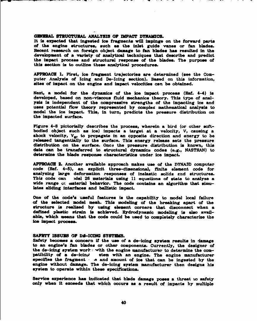
GENERAL STRUCTURAL ANALYSIS OF IMPACT DYNAMICS.It it expected that ingested ice fragments will impinge on the forward partsof the engine structures, such as the inlet guide vanes or fan blades.Recent research on foreign object damage to fan blades has resulted In thedevelopment of a variety of analytical techniques that describe and predictthe impact process and structural response of the blades. The purpose ofthis section in to outline these analytical procedures.
APPMACK 1. First, ice fragment trajectories are determined (see the Com-puter Analysis of Icing and De-Icing section). Based on this information,sites of impact on the engine and impact velocities can be obtained.
Next, a model for the dynamics of the ice impact process (Ref. 4-4) isdeveloped, based on non-viscous fluid mechanics theory. This type of anal-ysin is independent of the compressive strengths of the Impacting ice anduses potential flow theory represented by complex mathematical analysis tomodel the ice impact. This, in turn, predicts the pressure distribution onthe impacted surface.
Figure 4-8 pictorially describes the process, wherein a bird (or other soft-bodied object such as ice) impacts a target at a velocity, V, causing ashock velocity, V*, to propagate in an opposite direction and energy to bereleased tangentially to the surface. This energy release sets the pressuredistribution on the surface. Once the pressure distribution is known, thisdata can be transferred to structural dynamics codes (e.g., NASTRAN) todetermine the blade response characteristics under ice impact.
APPMACK 2. Another available approach makes use of the DYNA3D computercode (Refo 4-5), an explicit three-dimensional, finite element code foranalyzing large deformation responses of inelastic solids end structures.This code can 3del 26 materials using 11 equations of state to analyze awide range at material behavior. The code contains an algorithm that simu-lates sliding interfaces and ballistic impact.
One of the code's useful features in the capability to model local failureof the selected model mesh. This modeling of the breaking apart of thestructure is realised by using element corners that disconnect when adefined plastic strain in achieved. Hydrodynamic modeling in also avail-able, which means that the code could be used to completely characterise theice impact process.
SAPBUTY ISSUES OF bd-ICMIG SYSTDMS.Safety becomes a concern if the use of a de-icing system results in damageto an engine's fan blades or other components. Currently, the designer ofthe de-icing system wor-- with the engine manufacturer to determine the com-patibility of a de-icinjo stem with an engine. The engine manufacturerspecifies the fragment re and amount of ice that can be ingested by theengine without damage. The do-icing system manufacturer then designs hissystem to operate within these specifications.
Service experience has indicated that blade damage poses a threat to safetyonly when it exceeds that which occurs as a result of impacts by multiple
40

Target
A
Release
Stagnation Point
C
D
Figure 44-& Phaem of We Impact-(A) Initial Impact, (B) Impact Decay, (C) Steady Flow and(D) Termination (Rot. 4-4)
41
/V

1-1/2-pound bird,- as demonstrated by medium-sised blird ingestion testscurrently conducted under PAR 33.77. It is the opinion of one engine manu-facturer that replacing an ice-damaged blade will be a maintenance concernto the aircraft user rather than a serious safety consideration. A do-icingsystem that releases ice fragments which cause small dents to the bladeedge@ could, after oeveral icing encounters, cause cumulative denting thatfinally exceeds acceptable limits with respect to the engine manufacturers'maintenance specifications. This, then, becomes an economic concern for theaircraft user, who must decide whether to replace or to repair the blades.According to one engine manufacturer, this cumulative denting only becomes asafety issue if it exceeds the medium-simed bird strike damage, which may bea factor of 100 or more greater than the ice-caused denting described above.
SAFETY PRECAUTIONS APPLIED TO DE-IING SYSTEMS.This section describes the safety precautions anJ checks and balances thatshould be designed into de-!cing systems.
CYCLB TIMING. Contemporary de-icing systhms are operated either manually,as in many general aviation aircraft, or automatically. An automatic systemis one that, once activated, continues to cycle until de-activated by thepilot. A manual system cycles once per pilot activation. The most commonautomatically operated turbine engine inlet de-icing syer'ams areelectrothermal systems and pneumatic boots.
The most critical concern when setting the timing of a cyclical de-icer isthat the ice secreted between de-icing cycles be limited to levels that canbe tolerated by the engine when such ice is shed. When a cycle timer isinvolved, ice accretion rates must be determined for all flight regimes, anda worst-case accretion rate must be used to set the maximum allowable cycleintervaL
Mechanical de-icing systems offer more flasibility than thermal systems Incontrolling do-icing timing cycles. Due to the operational characteristicsof the anti-icing systems in large engines, ice ingestion has had to beaddressed from the worst-case situation in which all potentially accretedice is assumed to be ingested. This requirement it based on FAR Part 33.77("Delayed Actuation of the Anti-Ice System with Accreted Ice"). Thisapproach may not be applicable to a de-icing system. When activated, a de-icing system only removes ice from a portion of the inlet, whereas an anti-icing system, when activated, removes ice from the entire inlet at the sametime. Therefore, the amount of ice that an engine ingests in this worst-case situtation with a de-icing system is less severe than that with -nanti-icing system.
Zone-by-zone de-icing of an inlet is also advantageous in designing de-icingsystems that meet the ice ingestion tolerances of engines. To do this, theice ingestion tolerance of the engine must be known, and the fragment sizeand amount of ice shed with a particular type of de-icer must be evaluatedas to whether it falls within engine ingestion limits. The cycle intervalfor each zone would then be set to avoid ice accretion beyond that which canbe tolerated by the engine when the ice Is shed and ingested. (This isbased on the worst-came ice accretion rate for a particular inlet geometry).For proprietary reasons, the ice ingestion tolerances of engines were notavailable for inclusion in this study.
42

WATER RUNACIL Electrothermal de-icing systems need to be designed to mini-miss water runback. A common technique used to control water runback aswell as excessive power consumption is to alternately de-ice zones withinthe area to be ice protected. The forward zone undergoes a do-icing cyclefirst and causes some water to run back into the unheated aft zone, wherethe water then freemes. This aft sone then undergoes a do-icing cycle toremove the now frosen runback water.
PARTICLE SEPARATORS. Many turboprop and helicopter engines are equippedwith particle bypass ducting to minimise engine ingestion of ice or foreignobjects. This allows longer de-icing cycle Intervals than would be allowedif no particle spep-stion were used. Theme engines are generally smallerand inherently more sensitive to ice ingestion than the larger high-bypassturbofan engines.
Large turbofan engines do tor now and probably will not incorporate particleseparators such as those now used on the small engine x of helicoptors andturboprops. This means that shed ice will pass directly into the engine andimpact the fan, guide vanes and possibly the acoustic panels. For theseengines, the de-icing cycles must be set to minimize the size and quantityof ice shed into the engine.
IC$ DBETCTORS. The use of ice detectors as part of an automatic, closed-loop sensing and actuator system for do-icing will affect the de-icing cycletiming. Ice detectors will actuate a de-icer only when ice is actuallypresent, where.. a pilot would actuate a de-icer with a fixed, predeterminedcycle time either* when icing Is only suspected or after ice has accreted tovisible levels on the airhcaft's exterior. Zone-by-zone do-icing using anumber of ice sensors distributed around the circumference of the inletcould negate the advantage of an automatically controlled ice release sys-tem. If all detectors of the inlet simultaneously actuate de-icing of theirindividual sones, an excessive, potentially damaging quantity of ice couldbe released into the engine.
43

SUMMARY
Only a small percentage of engine manufacturers currently uue de-icing sys-tems. Those that do mainly uue electrothermal heaters or pneumatic boots.Do-icing systems will play an increased role in future aircraft turbineengine inlet ice protection. Engine manufacturers can facilitate the urseof energy-efficient de-icing systems by proper attention to detail in thedesign# development and qualification of new propulsion systems. By defin-ing acceptable approaches and criteria that do not adversely affect flightsafety, fuel savings can be realised through the adoption of de-icing sys-tern instead of anti-icing.
An analytical method could not be found for determining the size and amountof ice shed during de-icing of an inlet lip, but an empirical method hasbeen identified. This method suggests that a high-speed camera be used torecord the ice shedding process so that the ice fragments released from theinlet can be characterized as they exist prio~r to impacting any objects andbreaking. This method is described in the section entitled Engine Manufac-turer's Icing Experience.
An analytical method that predict. ice fragment impact locations was identi-fied for use in determining which parts of the engine/inlet sustain damagefrom ice dislodged from the inlet during de-icing. The first step of thisanalysis in to determine the trajectories of the shed ice. For this, exist-ing particle trajectory computer codes may be applied to predicting thepaths of shed ice fragments. This trajectory analysis identifies the enginecomponents impacted by the ice, such as acoustic liners, fan blades, enginecore, and guide vanes. Parallel to or in lieu of the trajectory/impactanalysis, engine service records may supply information regarding the enginecomponents susceptible to ice damage. A search of such records resulted inseveral discoveries. The first is that in over 24 million flying hours, notone incident of damage to acoustic liners has been attributable to ice shedfrom the inlet. Nor has there been any direct Ice damage to the engine com-pressor or outlet guide vanes, although some secondary damage to the enginecore resulted from fan blade damage caused by ice. Any severe fan bladedamage that occurred was at the tips of the fan blades. Severe fan bladedamage is critical because it can cause engine surgin. Two analyticalmethods were found that may predict the severity of fan blade damage causedby Ice impacts. These are described in the sections entitled Ice ImpactEffects on Engine Components and General Structural Analysis of ImpactDynamics.
Ice accretion rates may be determined for various icing conditions by usingthe computer codes discussed in the Computer Analysis of Icing and Do-Icingsection. Ice accretion would be controlled by matching the timing of thede-icing cycle to the rate of ice accretion. The timing of the do-icingsystem would be preset so the interval between do-Icing cycles is shortenough to keep ice accretion to a tolerable level-a level at which airinflow is not impeded and at which ice fragments released during de-icing donot damage the engine If Ingested. Automatic de-icing systems could use icedetectors to sense the rate of ice accretion and match the timing of the
44

cycle to the icing conditions. No information is available in the openliterature regarding allowable amounts of engine inlet ice accretion and anyassociated performance penalties.
Ice detector manufacturers report that ice detector development is nowadvancing from the icing advisory stage to measuring ice accretion rates andice thicknesses; however, integrated ice sensor/de-icing systems will onlyoccur if system reliability is ensured.
The technology surveys conducted as a part of this research effort predictedthe mid-1990s au the time frame when de-icing systems may find larger-scaleapplication. The next generation of engines, with their smaller compressorsand larger diameter fans, as well as the more advanced turboprop engineswill have less energy available for operating anti-icing systems. This doesnot mean that de-icing systems are restricted only to future applications.Several types of engines currently in service appear to be suitable for theshift from anti-icing to de-icing. Turboshaft, propfan, ducted propfan andturbojet engines are likely candidates. The motivation for this shift isthe desire to conserve energy
The process of certification of de-icing systems on turbine-engine inlets isnot expected to be very different from that now used for certifying anyother inlet ice protection systems. The certification procedures shouldinclude: a) design/analysis phase, b) icing wind tunnel testing (using mod-els if existing tunnels are too small for actual inlets) and c) icingflight testing. The icing wind tunnel test may be set up to simulate theactual or projected installation geometry and operating methods. This hasnot been required for large contemporary turbofan anti-icing systems, sincenew engines and nacelles are variations of existing installations withlittle or no change required for their anti-icing system design and opera-tion. Due to the maturity of current anti-icing systems for large turbo-fans, analysis and either dry or icing flight testing has proven adequatefor certification of some current transport aircraft. Until de-icing sys-tems proposed for use in large turbofan or propfan engines reach the !evelof confidence felt now for current anti-icing rystems, icing ground testsprobably will be needed to demonstrate de-icing performance.
A diagram of the process that an inlet de-icing system could undergo toachieve certification is shown in Figure 5-1. Am shown here, an emphasis isplaced on the major concerns for a de-icing system: ice accretion, ice shed-ding and ice impact/damage. The analyses and tests (due to lack of data,new systems may need both) are set up to allow the system designer to demon-strate to the FAA that: the system functions properly, the critical designconditions are defined, and the critical design conditions can be met. Thevarious loops within the path to certification allow the system designer tomodify the system operation (if necessary) to a configuration that willensure safe engine/aircraft operation in icing conditions.
45

E
46 "
IiC,

CONCLUSIONS
1. By defining acceptable approaches and criteria that do not adverselyaffect flight safety, fuel savings can be realized through the adoptionof de-icing systems instead of anti-icing.
2. An experimental method using a high-speed camera warn identified fordetermining the size and amount of ice shed during de-icing of an inletlip.
3. An analytical method to predict ice fragment impact locations wasn identi-fied in determining which parts of the engine/inlet sustain damage fromice dislodged from the inlet during de-icing.
4. Two analytical muethods were found that may predict the severity of fanblade damage caused by ice impacts.
5. Ice accretion rates may be determined for various icing conditions byusing computer codes to match the timing of the de-icing cycle to therate of ice accretion.
6. The technology survey conducted as a part of this research effort pre-dicted the mid-1990s as the time frame when de-icing systems may findlarger-scale application.
7. The process of certification of de-icing systems on turbine engine inletsis not expected to be very different from that now used for certifyingany other inlet ice protection system.
47

RBFRURICES
DR-ICING TBCIHNOLOGY STATUS
2-1 Haworth, L.A., "Pneumatie. Rotor Blade De-icing," VERTIFLITE, U.S. Army,September/October 1983. (Also AIAA Paper No. A83-46926).
2-2 Zumwalt, G.W. (Wichita State Universtiy) Personal Communication to H.A.Rosenthal (Rohr), October 2, 1987.
2-3 Zumwalt, G.W. and R.P. Frledberg, "Designing an Electro-Impulse De-icing System," AIAA Paper No. 86-0545, January 1986.
2-4 Zumwalt, G.W., "Electromagnetic Impulse De-icing Applied to a NacelleNose Lip," AIAA Paper No. 85-1118, July 1985.
2-5 Basrim, L. (NASA-Ames Research Center) Personal Communication to H.M.Rockholt (Rohr), April 7, 1988.
2-6 Nordwall, B.D., "NASA Tests Electro-Expulsive De-icer that Could Pro-tect F/A-18 Engines," Aviation Week and Space Technology August 3,1987.
2-7 Rotorcraft Icinj-Status and Prospects, NATO-AGARD Report No. 166,August 1981.
ICB ACCRRTION AND DR-ICING EVALUATION
3-1 Lewis, G.J., "De-Icing of Aerodynamic Surfaces Using ElectromechanicalImpulses," Ph.D. Thesis, Nottingham University, 1985.
3-2 Macklin, W.C., USAF Contract AF 61(053)-254, Technical Report No. 9,August 1960.
3-3 Michel, B. "A Mechanical Model of Creep of Polycrystalline Ice," Cana-dian Geotechnical Journal, 15:1-24, 1977.
3-4 Vinogrodov, A.M. "Constitutive Modeling of Ice," Proceedings of SixthInternational Off-Shore Mechanics and Arctic Engineering Symposium,Houston, Texas, March 1-6, 1987.
3-5 Sunder, S.S. and S, Nanthikesan, "A Tensile Fracture Model for Ice,"Proceedings of Sixth International Off-Shore Mechanics and Arctic Engi-neering Symposium, Houston, Texas, March 1-6, 1987.
3-6 Reyhner, T.A., "Transonic Potential Flow Computation About Three-Dimen-sional Inlets, Ducts and Bodies," AIAA Journal 19:1112-1121, September1981.
48

3-7 Reyhner, T.A., Computation of Transonic Potential Flow About Three-Dimensional Inlets. Ducts and Bodies, NASA CR-3514, March 1982; (BoeingDocument D6-49848).
3-8 Hess, J.L. and D.M. Friedman, "Calculation of Compressible Flow In andAbout Three-Dimensional Inlets With and Without Auxiliary Inlets by aHigher-Order Panel Method," NACA CR-168009, October, 1982.
3-9 Maskew, B., Program VSAHRO Theory Document NASA CR-4023, September,1987.
3-10 Magnum, E.E. and N.A. Epton, "PANAIR Computer Program for PredictingSubsonic or Supersonic Potential Flows About Arbitrary ConfigurationsUsing Higher Order Panel Method (Version 1.0), Vol. 1, Theory Document,NACA-CR 3251, 1980.
3-11 Stockman, N.O. and C.A. Farrell Jr., "Improved Computer Programs forCalculating Potential Flow in Propulsion System Inlet," NASA TM73728,July 1977.
3-12 Grashof, J., "Investigation of the Three-Dimensional Transonic FlowAround an Air Intake by a Finite Volume Method for the Euler Equations"Recent Contributions to Fluid Mechanics. ed. W. Ehase, Springer-Verlag,Berin, West Germany, 1982.
3-13 McCarthy, D.R. and T.A. Royhner, "Multigrid Code for Three-DimensionalTransonic Potential Flow About Inlets," AIAA Journal 20:45-50, January1982.
3-14 Papadakis, M. et al., "An Experimental Method for Measuring DropletImpingment Efficiency on Two- and Three-Dimensional Bodies," AIM PaperNo. 86-0406, January 1986.
3-15 Breer, M.D. and W. Seibel, Particle Trajectory Computer Program UserManual Boeing Document No. D3-0655-1, December 1974.
3-16 Kim. J.J., particle Trajectory Computation on a 3-Dimensional EntineInlet, NASA CR-175023, January 1986.
3-17 Normentp B.G., Calculation of Water Drop Trajectories to and aboutArbitrary Three-Dimensional Lifting and Nonlifting Bodies in PotentialAirflow, NASA CR-3935, October 1985.
3-18 MacArthur, C.D., "Numerical Simulation of Airfoil Ice Accretin," AIAAPaper No. 83-0112, January 1983.
3-19 Flemming, R.S. and R.J. Lednicer, "Correlation of Icing Relationshipswith Airfoil and Rotorcraft Icing Data," AIAA Paper No. 85-0337, Janu-ary 1985.
3-20 Hoerner, S.F., Fluid Dynamic Drag, published by author, Midland Park,New Jersey, 1958.
49

SAY2TY RQUIRINTS SUBSTANTIATION
4-1 Hoerner, S.F., Fluid Dynamic Drag, published by author, Midland Park,New Jersey, 1958.
4-2 Wilbeck, J.S., Impact Behavior of Low-Strength Projectiles, AFML-TR-77-134, July 1973.
4-3 Barber, J.P., H.R. Taylor and J.S. Wilbeck, Bird Impact Forces andPressures on Rigid and Compliant Targets," Technical Report AFFDL-TR-77-60, May 1978.
4-4 Boehman, L.I. and A. Challita, A Model for Prediction (sic) Bird andIce Impact Loads on Structures, APWAL-TR-82-2405, May 1982.
4-5 Hallquist, J.0. and D.J. Benson, DYNA3D User's Manual (NonLnearDynamic Analysis of Structures in Three Dimensions), UCID-19692, Rev.2, Lawrence Livermore National Laboratory, March 1986.
CONCLUSIONS
5-1 Cohen, I.D., "Preliminary Results of the AFGL Icing Study," Air ForceGeophysics Laboratory, AIAA Paper No. A83-38718, June, 1983.
5-2 Forester, G.O. and J.S. Orsechowski, "Icing and Its Measurement," A70-10692, Naval Air Propulsion Test Center, October 1969.
5o

APPUIDIX A -ICING CONDITIONS
Air contains water in the vapor phase. The maximum amount of water vaporpossible in any parcel of air is dependent on the air temperature. If cool-ing occurs, a temperature may be reached where the air can hold no morewater in the vapor state and in considered to be saturated--the relativehumidity is 100 percent. Further cooling results in condensation, with theexcess water vapor changing to liquid water. The water forms on condensa-tion nuclei-minute, hygroscopic (having an affinity for water) particlessuspended in the air. Sodium chloride particles from ocean spray, sulphateparticles of combustion and dust particles can all act as condensationnuclei. This is the primary process for the formation of clouds, but anextremely complex process that does occasionally result in anomolies. Witha high concentration of nuclei in the air, condensation can occur at rela-tive humidities less than 100 percent. When the condensation nuclei are inlow concentration or the nuclei are not hygroscopic, relative humidities inexcess of 100 percent (supersaturation) can occur.
When air temperatures are above freezing, the clouds formed do not impose athreat of aircraft icing. But when condensation occurs at or below 320'F,the cloud droplets formed are termed "supercooled." It is the instantaneousor near-instantaneous freezing of these supercooled water droplets impingingon the aircraft that is the most common cause of aircraft icing.
Supercooled clouds are common, especially where temperatures are not colderthan about 1510F; however, they have been found at temperatures as low as-40oF. These "colder" supercooled clouds are very unstable and can changeto ice rapidly if a few ice crystals are introduced or if agitation occurs,either by &tmompheric turbulence or aircraft passage. During the transitionperiod, when the cloud is composed of both ice crystals and water drorlets,it is known as a cloud of "mixed conditions."
When air temperature is appreciably below freezing, water vapor may crystal-lize onto nuclei as Ice without ever passing through a liquid phase. Cloudsthus formed consist entirely of minute, sustpended ice crystals. Snow isformed of aggregates of such ice crystals that have obtained sufficientsize and weight to overcome gravity, thus falling as precipitation. Flightthrough ice clouds or mixed condition clouds is usually not conducive toairframe icing but can be a serious icing problem for engines and engineinlets.
The type, amount and shape of accreted ice depend on: 1) atmospheric char-acteristics such as air temperature; liquid water content (LWC) of thecloud; and water droplet size [often referred to as MVD (median volumetricdiameter)] and 2) aircraft and flight variables such as airspeed; exposuretime; and size, geometry and skin temperature of aircraft components. Otherfactors, such as relative humidity, solar radiation and ambient pressure atflight level, sometimes have influence, but to a lesser degree.
Rime Ice forms when droplets freeze on contact with the aircraft surface andair is trapped in the ice, thus giving it a cloudy appearance. Glaze iceforms when droplets freeze while running back along the surface of the air-craft (or existing Ice). This type of ice appears clear.
A-1

APPESPR B - AM! IT I
T OP DI! ON BUSINESS W (PALOW W-) ILET.A bare turbofan inlet (no engine installed) was mounted in the NASA-Lewisicing wind tunnel. Several t.-pes of NIDI coil arrangements and mountingconfigurations were studied (Ref. B-i). lectric power levels (voltage andcapacitance) were varied (Table B-i) to determine efficiency of coil designfor each mounting configuration. Efficiency was defined as the lowest levelof power required to satisfactorily remove ice.
Table B-1. Electric Power Variables In EIDI Test on Business Jet Inlet
De-Icing VariablesCapacitance (/Af) 200 300 400 600Voltage (V) 800 1000 1200 1400 1600
Initially, tests were run through the range of icing conditions shown inTable B-2, which were selected from the FAR Part 25 Appendix C icing enve-lope. The worst-case icing conditions were determined and used for most ofthe later testing. For RIDI, these conditions are warm air and light water,which produce wet and slushy ice. NIDI became effective in removing ice atthicknesses of one-eighth inch and greater.
Table 8-2. Iclig Condition Variables In EIDI Test on Business Jet Inlet
Icing ConditionsAngle of Attack (deg.) 0 10Tunnel Air Temperature (OF) 15 27Tunnel Airspeed (mph) 110 170 225Water Droplet Diameter (Dim) 12 13 15 20Liquid Water Content (g/m3) 0.60 0.85 1.20 1.65 2.40
The five different types of coil-mounting methods tested are illustratedschematically in Fig. B-1. Coils were installed on the inlet lip at thenumbered circumferential positions shown in Fig. B-2. Coils were testedindividually and in combinations to evaluate local and interactive effectsof BIDI. De-icing of an iced inlet lip could be observed visually as shownin Fig. B-2. In this case, coils at position 7 had been activated. Fromthese performance tests, it was concluded that skin-mounted coils de-icedmost efficiently (Ref. B-i). The second-mont efficient arrangement was thebulkhead-mour.ted paired side coils.
B-1

Bulkheind-ountedSingle Side Coll
BulkheadDoubler
Bulkhead-MountedPaired Side Coils
Five Coll-MountingConfigurations ~ ~Bulkhead-Mounted
Nose Coil
Skin-MountedSide Coil
Coil Mount
Skin-MountedNose Coil
Figure B-i. EDI Coll-Mounting Configurations-Schematic sections of aninlet lip showing different types of coil-mounting configurationstested on the business jet inlet.
B-2
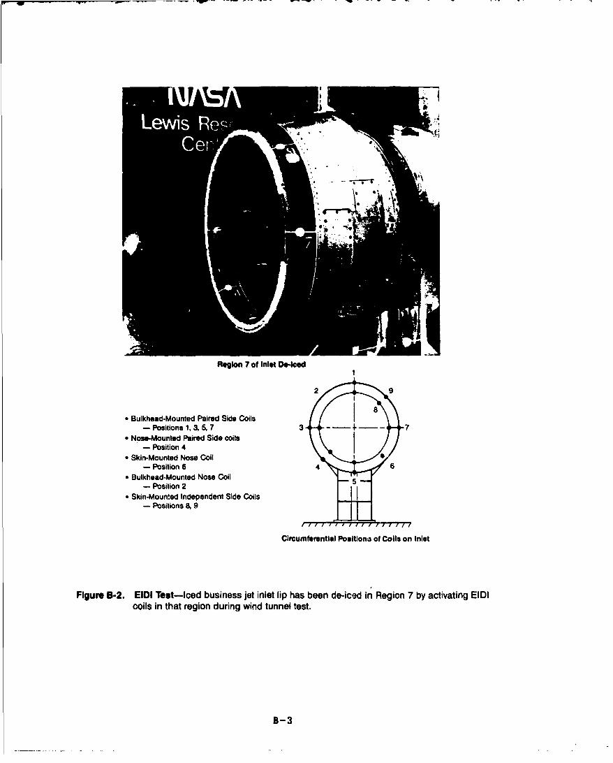
Region 7 of Inlet Do-Iced
2 9
"* Bulkhead-Mounted Paired Side Coils- Positions 1, 3 5, 7 3 7
"* Nose-Mounted Paired Side coils- Position 4
"* Skin-Mounted Nose Coil- Position 6 46
"* Bulkhead-Mounted Nose Coil 5- Position 2
"* Skin-Mounted Independent Side Coils- Positions 8, 9
Circumferential Positions of Coils on Inlet
Figure B-2. EIDI Test-iced business jet inlet lip has been de-iced in Region 7 by activating EIDIcoils in that region during wind tunnel test.
B-3

Each of these two coil-mounting conf igurations war then tested over thewhole circumference oft an inlet lip. These tests confirmed the successfulperformance of the two mounting configurations during repeated de-icingcycles throughout long icing durations (30 minutes). In addition, an opti-mum circumferential coil spacing (the largest interval between coils thatresults in de-icing of ýhe entire region) of 18 to 20 inches was deter-mined. Based on the the business Jet tests# estimates could be made of thepower that would be required to effectively de-ice larger diameter inletsfor turbof ans. Table B-3 compares these estimates.
Shed ice fragmentA were caught so that their size and shape could be deter-mined. Ice shed by RIDI in this test was one-eighth inch thick and fragmentdiameter. were approximately three-eighths inch. This means the thickness-to-diameter aspect ratio was approximately 3:1. Further testing should becarried out to determine whether this ratio can be generalized to other icethicknesses.
TEST OF NMID ON TURBOPROP (PWI24) INLET.The NASA-Lewis Icing Research Tunnel was used to test HIDI on a bare inletlip (no engine installed) designed for turboprop engine installation. Me-tallic doublers were bonded to the lip surfaces between the surface and eachcoil (as shown in Fig. B-1). This was the first test of BIDI in a compositeinlet and was made in preparation for the test of EID! on a composite turbo-prop inlet installed on an operating engine.
The purpose of the teat was to determine the power needed for effectivede-icing on a composite inlet lip. Testing conditions were similar to thoseof the metal business Jet inlet (Ref. B-i). The composite inlet lip demon-strated good structural response, flexing and rippling during the electro-magnetic impulses without breaking, but with enough displacement to expelthfi ice. Ice was shed effectively at electric power levels similar to thosefound to be effective in the business jet inlet. The thickness of ice shedwas also similar for the two types of inlet.
Tsbie B-3. Estimates of Power Required to De-ice Different Sizes of Engine Inletswith EIDI (Bulkhead-Mounted Paired Side Coils; One-Minute CycleOn-Times)
Inlet TotalDiameter Power No. Coil
(Feet) (Watts) Stations2.5 40 65.0 180 127.5 360 18
10.0 640 24
B-4S

TEST OF HID! ON M3u'OPROP JUL.R ON AN OP•EATM MQDRIDI was tested on the inlet of an operating turboprop engine (PW124)mounted in the Canadian National Research Council icing wind tunnel inOttawa. The power level and timing of impulse cycles used were those deter-mined from the previous test of the bare turboprop inlet to be the mostefficient. Testing in this case was conducted similarly to FAA engine/inletcertification testing, with careful attention given to simulating FAR Part25 Appendix C icing conditions and run durations. The inlet was equippedwith a particle bypass duct, causing most, if not all, shed ice to bypassthe engine, thus avoiding any concern with effects of ingested ice on theengine. SIDI performed satisfactorily for all conditions tested. Low.-tem-perature conditions (0°F to -22 0 F) were not tested, due to the environmentalconstraints of the facility. However, the results of the NASA-Lewis testshad already demonstrated that SIDI performs best in this low-temperaturerange.
Based on the two turboprop tests, SIDI appears to be a good candidate forice protection on turboprop engine inlets, provided other considerationssuch as reliability, maintainability, resistance to fatigue, and cost areacceptable.
TUST OF SIDI ON LAWNI DIAMETMR (A310) TURBOFAN INLRT.A one-quarter span of a large (eight-foot diameter) turbofan inlet wasmounted in France's Centre D'Essais Des Propulseurs R-2 icing wind tunnel(Fig. B-3). A four-foot diameter uniform icing cloud was produced, whichexposed a 75- to 80-degree span of the inlet to icing. Six SIDI coil sta-tions were equally spaced over the span of the inlet, approximately one footapart, with two coils per station. Testing conditions again reflected theFAR Part 25 Appendix C icing envelope. The results of this test providedinformation about large diameter inlet configurations. The minimum icethickness at which SIDI became effective was the same as in previous tests-one-eighth inch.
Fo Directon
Figure B-3. One-Quarter Section of Turbofan Inlet as Mounted for Testing in Icing Tunnel
B-5

4Excellent viewing of shed ice was accomplished by filming many do-icingcycles at 1,000 and 4,000 frames per second. This data was edited intovideotape format and analyzed to determine ice particle size, shape andshedding trajectory. Ice particles shed from the larger (A310) turbofaninlet had a higher diameter-to-thickness ratio (10:1) than ice particlesshed from the smaller inlets of business jet and turboprop engines, whichhave a 3:1 ratio.
SKIN FATIGUB TBSTS.An EIDI system relies on deformation of the aircraft skin for its operation;therefore, it subjects the skin to stress. Consequently, fatigue resistanceof the structure must be considered.
Fatigue tests of two light Cessna general aviation airplane wings were con-ducted at Wichita State University. Using environmental temperatures andde-icing power levels similar to those in previous tests, no structuraldamage to the wings was apparent after 15,000 EIDI de-icing impulses. Acomposite leading edge was similarly tested for 20,000 cycles with no struc-tural damage. In fatigue studies of a large transport aircraft wing slat atmuch higher voltages (3,000 volts), the wing slat withstood 69,000 impulsesbefore showing signs of fatigue (cracks in the skin). Thus, fatigue doesnot appear to be a concern. However, given the complexity of the task ofanalyzing the dynamic response (i.e., vibrational modes) of a realisticstructure to an EIDI impulse and predicting accurate structural stresses, afatigue test of any new BIDI installation should be carried out.
TEST OF NID! ON A FULL-SIZE BNGINB INLET.An EIDI system was tested on a full-size engine inlet in the Rolls-RoyceHucknall icing wind tunnel. The purpose of these tests was to demonstrateEIDI's performance over a range of atmospheric icing conditions (temper-ature = -5 0 C, -10 0 C , -20OC; LWC = 0.6g/cmý airspeed = 253 fps; dropletsize = 20 microns). A high LWC was selected to achieve a high rate of iceaccretion between pulses, thereby decreasing time required for the testing.The test temperature range produced both rime and glaze ice. No tests werecarried out in simulated ice crystal conditions. These tests reverled thefollowing aspects of BIDI that will require attention during the designstage.
AIRCRAFT STRUCTURE INFLUBNCBS WAVE PROPAGATION. The principle ofoperation of BIDI is to set up mechanical disturbances in the aircraft skinto be de-iced. The magnitude of the disturbance decays with time anddistance from the coil. If there is sufficient distance between structuralsupports of the aircraft skin (such as spars or ribs), waves originating inthe skin over the coil may travel relatively long distances in the skinuntil they dampen out naturally. If the intervals between skin supports areless than 10 coil diameters spanwise or less than five diameters chordwise,waves are reflected from the supports and are of relatively large amplitudecompared with the original disturbance. Constructive interference canresult, setting up standing waves in the skin, thereby improving theefficiency of the system.
B-6

Actual HIDI installations tend to be a combination of theme circumstances.In the chordwise direction, both wing leading edges and engine inlet lipshave skin supports close to the coils. Standing waves can be set up in thisdirection, and therefore, coil size and positioning become important forgood de-icing performance. Coils that are poorly positioned or coils thatare too big compared to the distance between structural nodes will causedestructive interference of the induced waves, resulting in low amplitudedisplacements and, thus, reduced HIDI efficiency.
Spanwise wave propagation may differ greatly from chordwise propagation. Ifno ribs are present in a wing, traveling waves are not reflectod but decaynaturally. Similarly, most engines have inlet cowls supported only at therear. Coil positioning in the circumferential direction is not critical forgood pulse propagation, but circumferential spacing must be addressed foreffective de-icing between coils.
NL•DTRICAL DBSIGN. EIDI works on the principle of electromagnetic induc-tion. For best results, the aircraft skin adjacent to the EIDI coil shouldbe non-magnetic and have high electrical conductivity. EIDI has been usedwith composite aircraft skins by means of attaching a metal plate (a doub-ler) (Fig. B-1) to the skin adjacent to the coil.
Due to the high electrical currents passing through the coils of an HIDIsystem, connecting wires will repel each other. They will also be repelledby any metallic structures close to them. The forces involved are rela-tively small but are sufficient to move the wires if they are not secured atfrequent intervals. Chafing of insulation and fatigue fracture of cables attheir connecting points have been noted by some BIDI researchers. Theseproblems can be resolved provided they are recognized early in the designstage.
Another important factor relating to the design of the EIDI system in light-ning strike resistance. Lightning striking the engine inlet or wing leadingedge must be provided with a low-resistance path back to the main aircraftstructure in order for it to dissipate harmlessly. If this path is notprovided, a lightning strike could provide very high voltage into the BIDIsystem and destroy it.
COIL-MOUNTING BRACKErTS. The coil-mounting brackets are subjected to thesame load as the afrcraft skin. This may be as high ai 900 lbs. (4KN) perimpulse over the coil area. Each impulse lasts approximately 0.5 to 1.0millisecond. The mounting brackets must be designed for these loads. Amajor purpose of the mounting bracket is to maintain the correct coil-to-skin gap. The brackets should limit deflection of the coil during animpulse to 0.010 inch (0.25 mm) or less to prevent the coil and skin fromcoming into contact.
The coil brackets should not affect the magnetic field produced by the EIDIcoil. Materials which are non-magnetic and non-conducting should be used.For example, glass fiber composites are preferred over electrically conduct-ing carbon fiber.
B-7
20

STRUCTURAL DYNAMICS.Since EIDI removes accreted ice by a process which applies localized rapidaccelerations to aircraft surfaces, it was realized that structural dy-namics analysis was a necessary design and development tool. However, foran optimum structural dynamics analysis, it is necessary to specify theforce-versus-time (forcing function) that an EIDI system imparts to thestructure.
Wichita State University (WSU) and NASA developed an electrodynamic analysiscomputer code that serves this purpose. Based on EIDI system physicalparameters such as coil size, spacing, voltage, capacitance, inductance, andwire resistance, the code calculates electrical response of the system andoutputs a force-versus-time function (Ref. B-2). This function can serve asthe input for the structural dynamics analysis.
WSU also developed a structural dynamics model that produces an outputconsisting of a set of natural frequencies, vibrational mode shapes, accel-erations displacements and stresses. These calculated stresses and dis-placements were compared to data from structural response tests of actualhardware conducted at WSU. The analysis results correlated well with thetest data.
With such a structural dynamics model, numerous design iterations can beproduced to: (1) evaluate materials; (2) determine optimal locations forEIDI inductor coils; (3) determine impulse response of the aircraft skin;and (4) predict loads imparted in local aircraft structure and associatedmounting hardware. The loads and structural responses would then be used topredict fatigue life.
SIDI ENERGY CONSUMPTION.The amount of energy required to remove accreted ice from a surface usingan EIDI system is calculated below and compared to the amount of energyrequired for other types of ice protection. As evident from these figures,electromagnetic impulse de-icing is much more energy-efficient than eitherevaporative anti-icing or thermal methods of melting ice.
EIDI tests have indicated that two impulses per coil station arerequired to remove accreted ice.
The energy consumed per impulse (Ei) is:Ei = 0.5CV2 = 200 joules
(where C = 400 microfarads and V = 1,000 volts).
The energy consumed per coil station (E.) is:Es = 2Ei = 400 joules = 0.38 BTUs.
This amount of energy will remove a 0.1"-thick layer of ice over an18" x 6" area.
The mass of ice removed = (ice density) x (ice volume)= (0.0325 lb/in3 ) x (18"x6"xO.l") = 0.35 lb.
The energy required for EID! = 0.38 BTU/0.35 lb = 1 BTU/lb.
B-8

In comparison:
Task fter gy Required(3!U/lb)
Evaporate Water 1,000"Melt Ice 144*Remove Ice with EIDI 1
'Additional energy is needed above these values for thermal systemsbecause of heat losses.
APFMFII 3 B F•
B-I Nelepovitz, D.O. and H.A. Rosenthal, "Electro- Inpulse De-icing of Air-craft Engine Inlets," AIAA Paper No. 85-0546, January 1986.
B-2 Bernhart, W.D. and R.L. Schrag, "Electro-Iimpulse De-Icing Electro-dynamic Solution by Discrete Elements," AIAA Paper No. 88-0018, January1988.
I
B-9

hP2WII C - DISTRIIUTION LIST
No. No.
Recipient Copies Recipient Copies
ATA of America 1 DOT/FAA Central Region 1Attn: Dick Tobiason ACE-661709 New York Avenue, NW 601 East 12th StreetWashington, DC 20006 Federal Building
Kansas City, MO 64106Boeing Commercial Airplane Co. 1Attn: Walt Bauerueister, MS 9W-60 DOT/FAA Great Lakes Region 2P.O. Box 3707 AGL-60Seattle, WA 98124-3707 O'Hare Office Center
2300 East Devon AvenueBoeing Cotmercial Airplane Co. 1 Des Plaines, IL 60018Attn: Doug CosbyP.O. Box 3707 DOT/FAA National Headquarters 2Seattle, WA 98124-3707 ADL-l
800 Independence Avenue, SWBoeing Cc mercial Airplane Co. 1 Washington, DC 20591Attn: Derek Rouse, MS 6L--65P.O. Box 3707 DOT/FAA National Headquarters 2Seattle, hA 98124-3707 ADM-1
800 Independence Avenue, SWBoeing-Vertol Company 1 Washington, DC 20591Attn: Andy Peterson, MS 32-16P.O. Box 16858 DOT/FAA National Headquarters 2Philadelphia, PA 19142 ALG-300
800 Independence Avenue, SWBritish Embassy 1 Washington, DC 20591Civil Air Attache ATS3100 Mass Ave., NW DOT/FAA National Headquarters 2Was0" 'ton, DC 20008 APA-300
800 Independence Avenue, SWCiv...i aviation Authority 1 Weshington, DC 20591Aviation House129 Kingsway DOT/FAA National Headquarters 2London WC2B 6NN, England ASF-1
800 Independence Avenue, SWContinuum Dynamics, Inc. 1 Washington, DC 20591Attn: Dr. Alan BilaninP.O. Box 3073 DOT/FAA National Headquarters 2Princeton, NJ 08543 ASF-100
800 Independence Avenue, SWDirector DuCentre Exp de la 1 Washington, DC 20591Naviation Aerineene
941 Orly, France DOT/FAA National Headquarters 2ASF-200
DOT/FAA AEU-500 4 800 Independence Avejue, SWAmerican Embassy, APO Washington, DC 20591New York, NY 09667
C-1

No. No.
Recipimnt Copie Recipient Copie
DOT/FAA National Headquarters 2 FAA Anchorage ACOASF-300 701 C Street, Box 14800 Independence Avenue, SW Anchorage, Ag 99613Washington, DC 20591
FMA Atlanta ACO
DOT/FAA National Headquarters 2 1075 Inner Loop RoadAVS-1 College Park, GA 30337800 Independence Avenue, SWWashington, DC 20591 FAA Boston ACO
12 New England Executive ParkDOT/FAA National Headquarters 2 Burlington, MA 001803AVS-l00800 Independence Avenue, SW FAA Brussels ACOWashington, DC 20591 American Embassy, APO
New York, NY 09667DOT/FAA National Headquarters 2AVS-200 FAA Denver800 Independence Avenue, SW 10455 East 25th AvenueWashington, DC 20591 Suite 307
Aurora, CO 98168DOT/FAA National Headquarters 2AVS-300 FAA Long Beach ACO800 Independence Avenue, SW 4344 Donald Douglas DriveWashington, DC 20591 Long Beach, CA 90808
DOT/FAA National Headquarters 2 FAA Los Angeles ACOAWS-l P.O. lox 92007800 Independence Avenue,SW Worldway Postal CenterWashington, DC 20591 Hawthorne, CA 90009
DOT/FAA Mike Monroney 2 FAA New York ACOAeronautical Center 181 So. Frankline Ave., Re 202
AAC-64D Valley Stream, NY 11581P.O. Box 25082Oklahoma City, O 73125 FMA Seattle ACO
Attn: Mark Qua.DOT/FAA Southwest Region 2 17900 Pacific Highway So.ASW-53B C-68966P.O. Box 1689 Seattle, WA 98168Fort Worth, TX 76101
FAA Wichita ACOEmbassy of Australia 1 Mid-Continent AirportCivil Air Attache Room 100 FAA Building1601 Mass. Ave., NW 1891 Airport RoadWashington, DC 20036 Wichita, KS
FAA, Chief 1 General Electric CompanyCivil Aviation Assistance Group Attn: Dick KellerMadrid, Spain Aircraft Engine GroupAmerican Embassy, APO Cincinnati, OH 45215New York, NY 09285-0001
C-2

No.
Recipient Copies No.Recipient Copies
McAir Propulsion SystemsAttn: A.M. Espinosa, MS 425 USAF Flight Test CenterSt. Louis, MO 63136 Attn: Kelly Adams
G520 Test Group/ENAS 239Naval Air Propulsion Center I Edwards Air Force Base, CA 93532P.O. Box 7176Trenton, NJ 08628 Mr. Richard Adams 2
National Resource SpecialistNaval Air Test Center 1 AWS-104Attn: Brion Picard FAAFlight Systems Dept. 800 Independence Avenue, SWPatuxent River, MD 20670 Washington, DC 20591
Northwestern University 1 Mr. Al AstorgaTrisnet Repository FAA (CAAG)Transportation Center Library American Embassy, Box 38, APOEvanston, IL 60201 New York, NY 09285-0001
Scientific & Tech. Info FAC 1 Mr. C. Scott Bartlett 1Attn: NASA Rep. Sverdrup Technology, Inc.P.O. Box 8757 BWI Airport USAF Arnold EngineeringBaltimore, MD 21240 Development Center
Arnold Air Force Station, TN 37389Sverdrup Technology, Inc. 1Attn: Dr. J.D. Hunt, T-327 Mr. Gale BradenNSTL, MS 39529 FAA
5928 Queenston St.Sverdrup Technology, Inc. 1 Springfield, VA 22152Attn: Tom MillerBox 30650 Mr. Burton Chesterfield, DM.A-603 1Middleberg Heights, OH 44130-9998 DOT Transportation Safety Inst.
6500 South McArthur Blvd.University of California 1 Oklahoma City, OK 73125Service Dept. Institute ofTransportation Standard Lib Mr. Gary Frings 50
412 McLaughlin Hall Flight Safety Research BranchBerkely, CA 94720 ACT-340
FAA Technical CenterUniversity of Michigan 1 Atlantic CityAttn: Gary Ruff International Airport, NJ 08405Dept. of AerospaceAnn Arbor, MI 48104 Mr. Bill Ga4tskill
U.S. Army AviationUSAF Aeronautical Systems CommandSystems Division 4300 Goodfellow Boulevard
Attn: Steve Johnson AMSAV-9DASD-WE St. Louis, MO 63120Wright-PattersonAir Force Base, OH 45433-6503 Dr. John Hansman
Massachusetts Instituteof Technology
Department of AeronauticsCambridge, MA 02139
C-3

No. No.
Recipient Copies Recipient Copies
Mr. Paul Hawkins 1 Mr. Frank Taylor 1Propulsion Branch, ANI-140S 3542 Church RoadFAA Ellicott City, MD 2140317900 Pacific Highway SouthC-68966 Mr. William T. Westfield 1Seattle, WA 98168 Manager, Engine/Fuel Safety
Branch, ACT-320Mr. Robert Koenig 1 FAA Technical CenterEngine and Propeller Atlantic CityStandards Staff, AME-110 International Airport, NJ 08405FAA12 New England Executive Park AAC-64D 2Burlingtcn, MA 01803
AAL-400 2Dr. Kenneth Korkin 1Texas A&M University ACE-66 2Department ofAeronautical Engineering ACT-5 2
College Station, TX 77840ACT-61A 2
Dr. Hans A. Krakauer 1Deputy Chairman ADL-1 1International Airline PilotsAssociation Group ADL-32 North 1
Apartado 978200 Albufeira, Portugal AEA-61 3
Mr. Geoffrey Lipman 1 AES-3 1Executive Director,President du Conseil AGL-60 2
International Foundation ofAirline Passenger Associations ALG-3900 1
Case Postale 462, 1215 Geneve15 Aeroport, Swisse, Geneva ANE-40 2
Mr. Richard E. Livingston Jr. 1 ANM-60 2Director, Aerotech Operationsfor the IAPA Group APA-300 1
1805 Crystal DriveSuite 1112 South APM-1 1Arlington, VA 22202
APM-13 Nigro 2Mr. Byron Phillips 1National Center for ASO-52C4 2Atmospheric Research
Research Aviation Facility ASW-53B 2P.O. Box 3000Boulder, CO 80307 AWS-100 1
Dr. Joe Shaw I M-493.2 5NASA-Lewis Research Center21000 Brookpark RoadMail Stop 86-7Cleveland, OH 44126 C-4