Dental Handpiece Sterilizer - Booth Medical-001...Inspect power cord and all wiring for damage. Be...
79
FOR USE BY MIDMARK TRAINED TECHNICIANS ONLY Model Numbers: Service and Parts Manual M3 UltraFast ® Dental Handpiece Sterilizer M3 -001 thru -004 004-0520-00 Rev. A (1/9/13) SA104100i
Transcript of Dental Handpiece Sterilizer - Booth Medical-001...Inspect power cord and all wiring for damage. Be...

FOR USE BY MIDMARK TRAINED TECHNICIANS ONLY
Model Numbers:Service and
Parts Manual
M3 UltraFast® Dental Handpiece Sterilizer
M3 -001 thru -004
004-0520-00 Rev. A (1/9/13)
SA104100i

ii© Midmark Corporation 2010 SF-1889 [Revised: mo/dd/yr]
Tabl
e of
Con
tent
sGENERAL INFORMATION
Symbols .......................................................... ivOrdering Parts ................................................ ivSerial Number Location .................................. ivSpecifications .................................................. v Scheduled Maintenance ................................. vi Cycle Parameters ...........................................vii Warranty Information .....................................viii
TROubLEshOOTINGError Codes ................................................. A-2Power Up / Select Cycle Mode .................. A-15Door Close Mode ....................................... A-16 Heat Up Mode ........................................... A-17 Sterilization Mode ...................................... A-18 Vent Mode ................................................. A-19 Door Open Mode ....................................... A-20Dry Mode ................................................... A-21
TEsTING & REpAIRActivating Service Diagnostics .................... B-2 Test Selection Screen .................................. B-3 Vent Valve Test ............................................ B-4 Door Motor Test ........................................... B-6 Water Pump Test / Priming Instructions ...... B-9 Boiler Test .................................................. B-13 Dry Heater Test.......................................... B-15 Condensation Heater Test ......................... B-17 Door / Tray Position Switch Display Screen .......................................... B-19 Chamber Pressure Display Screen ........... B-20 Temperature Display Screen ..................... B-21 Water Level / External Tank Sensor Display Screen .............................. B-22 Error Code Display Screen ........................ B-23 Key Test Display Screen............................ B-24 Five Point Leak Test .................................. B-25 Temperature Sensor Resistance Test ....... B-26
Gen
eral
Info
Sec
tion
A
Sec
tion
E
Sec
tion
B
Sec
tion
CS
ectio
n D
(*) Indicates multiple pages due to model / serial number break(s).
AccEss pROcEduREsTop Cover Removal / Installation ................. C-2
WIRING dIAGRAMsM3 ................................................................ D-2
ExpLOdEd VIEWs / pARTs LIsTComponents Overview ................................ E-2Main Enclosure ............................................ E-3Main Components ....................................... E-4 Door Tray Latch Mechanism ....................... E-5* Boiler Assembly ........................................... E-6 Pump Solenoid Assembly ............................ E-7 Reservoir Assembly ..................................... E-8 PC Board Assembly..................................... E-9 Switch Harness Assembly ......................... E-10 Plumbing and Tubing Components ............E-11 Door / Tray Accessory ............................... E-12 External Condensing Tank......................... E-13 Shipping Packaging ................................... E-14 Label Location ........................................... E-15
cONTINuEd ON NExT pAGE
iii© Midmark Corporation 2010 SF-1889 [Revised: mo/dd/yr]
Tabl
e of
Con
tent
sD
igita
lly L
inke
d Fi
les
(*) Indicates multiple pages due to model / serial number break(s).
REpAIR pROcEduREs & FORMsDoor Seal Installation ....................003-1773-00 External Condensing Tank Installation .....................................003-1713-00 PCB Installation .............................003-1775-00 Boiler Installation ...........................003-1776-00 Water Pump Installation ................003-1777-00 Door Motor Installation ..................003-1778-00 Boiler O-ring Installation ................003-1779-00 Boiler Assembly Installation ...........003-1780-00 Front Cover Installation .................003-1781-00 Membrane Switch Installation ........003-1782-00 Pressure Relief Valve Installation .....................................003-1783-00 Pump Plug Diode Installation ........003-1784-00Pump Assembly Installation ........... 003-1785-00 Solenoid Installation ......................003-1785-00 Switch Harness Installation ...........003-1787-00 Thermostat Installation ..................003-1788-00 Interlock Assembly Installation ......003-2059-00 Parts Order Form ...........................004-0755-00 Comments Form ............................004-0456-00

iv© Midmark Corporation 2010 SF-1889 [Revised: mo/dd/yr]
Gen
eral
Info
rmat
ion dANGER
Indicates an imminently hazardous situation which will result in serious or fatal injury if not avoided. This symbol is used only in the most extreme conditions.
WARNING Indicates a potentially hazardous situation which could result in serious injury if not avoided.
Equipment Alert Indicates a potentially hazardous situation which could result in equipment damage if not avoided.
caution Indicates a potentially hazardous situation which may result in minor or moderate injury if not avoided. It may also be used to alert against unsafe practices
symbols
Indicates the function / component is working properly. No action required.
Indicates the function / component is working, but a problem exists.
Indicates the function is not working at all, or that the component is faulty.
Ordering partsThe following information is required when ordering parts: • Serialnumber&modelnumber • Partnumberfordesiredpart [Refer to Section E: Exploded Views & Parts Lists] Non-warranty parts orders may be faxed to Midmark using the Fax Order Form in the back of this manual. For warranty parts orders, call Midmark’s Technical Service Department with the required information. Hours:8:00amto5:00p.m.EST(MondaythruFriday) Phone:1-800-Midmark(1-800-643-6275)
serial Number Location
NoteUsed for special instructions or additional information.
SA103100i
Serial Number VXXXXXX
VXXXXXX
VXXXXXX
Thesymbolsbelowmaybeusedinthismanualtorepresenttheoperationalstatusofsterilizerfunctionsandcomponents.

v© Midmark Corporation 2010 SF-1889 [Revised: mo/dd/yr]
General Information
Weights, Dimensions, Electrical Specifications
NoteTo ensure unit is properly grounded, it must be connected to a matching grounded, dedicated, correctly polarized receptacle.
Electrical Ratings: 115 VAC Unit CircuitRequirements*......................120VAC,50/60Hz,12amp Max.PowerConsumption................1400watts 230 VAC Unit CircuitRequirements*.....................230VAC,50/60Hz,6amp Max.PowerConsumption...............1400watts *Power source must have over voltage limits less than 1500 watts from mains to ground. (Installation Category ll in accordance to IEC 664) Fuse Ratings: 115 VAC Unit F1....................................................15Amp,250V,FastActing,1/4"x11/4" F2....................................................0.25Amp,250V,Slo-blo,1/4"x11/4" 230 VAC Unit F1....................................................8Amp,250V,FastActing,5x20mm F2....................................................0.125Amp,250V,Slo-blo,5x20mm Certifications: ASMEBoiler&PressureVesselCode,SectionVIII,Division1 CanadianRegistrationNumberAvailable UL61010-12ndEdition IEC61010-2-0401stEdition CAN/CSA-C22.2No.61010-12ndEdition FCCPart15,Sub-partB Physical Dimensions: OverallLength(A):................................21in.(53.3cm) OverallWidth(B):..................................17.8in.(45.2cm) OverallHeight(C):.................................6.9in.(17.5cm) ShippingCartonLength:.......................25in.(63.5cm) ShippingCartonWidth:.........................22in.(55.9cm) ShippingCartonHeight:........................16.6in(42.2cm) CounterArea:.......................................24in.(61cm)deepx22in.(55.9cm)wide ChamberVolume:.................................0.49gal(1.8liter)
Weight: EmptyReservoir:.........................................71lbs.(32.2kg) FullReservoir:.............................................80lbs(36.3kg) WithShippingCarton:..................................80lbs(36.3kg) Water Reservoir Capacity: ........................1.20 gal (4.5 liter) Pressure Relief Valve Setting:....................40PSI(275.8kPA) Chamber Pressure: @270°F(132°C).................................27.1PSI(186.2kPA)
C
AB
SA105900i

vi© Midmark Corporation 2010 SF-1889 [Revised: mo/dd/yr]
scheduled Maintenance / cleaning chart
Interval Inspection / Service Description
Periodically
Cleaning
Cleanexternalsurfaces,tray,&chamberwithmildsoapanddistilledwater.Wipedry.
Cleandoorgasket&matingsurfacewithadampcloth. Inspectgasketfordamage,replacegasketifnecessary.
Emptywaterfromcondensingtank.Cleantankwithdilutedbleachsolution(1/4 cup bleach : 1 gallon water)&abrush. Rinsetank,thenfilltotheminimumwaterlevelindicatorline.
ObviousDamage Visuallyinspectcomponentsfordamagethatcouldcauseproblemsduringoperationorunsafeoperation.
Drain/RefillReservoir Usingthedrainhose,drainallwaterfromthereservoir. Refillreservoirwithdistilledwater.
Hardware Allfastenersmustbepresentandfastenedsecurely.
ElectricalSystemInspectpowercordandallwiringfordamage.
Besureallelectricalconnectionsaretight.
Monthly Cleaning
Remove&cleanfilterusingamildsoapsolution&abrush,Placeinultrasoniccleanerifnecessary. Rinsewithdistilledwater.Cleancondensingtanklevelsensorswithmildsoapsolution. Wipedry.
DateofService:
Location:
ServiceTechnician:
ModelNumber:
SerialNumber:
Notes:

vii© Midmark Corporation 2010 SF-1889 [Revised: mo/dd/yr]
CYCLE STERILIZATION PARAMETERS DRY TIME ITEMS TO BE STERILIZED
Unwrapped
Temperature: 270° F (132° C)
Pressure: 27.1psi(186kPa)
Time: 3:30Minutes
Time:25Minutes
•DentalInstruments/handpiecesloose on a tray. •Otheritemsmanufacturersrecommendfor exposureat270° F ( 132°C),looseonatray.
Pouches
Temperature: 270° F (132° C)
Pressure: 27.1psi(186kPa)
Time: 5:30Minutes
Time:30Minutes
•DentalInstruments/handpiecesinpouches, wrapped,orinawrappedcassette. •Otheritemsmanufacturersrecommendforexposure at270° F ( 132°C),inpouches,wrapped,orina wrappedcassette.
Low Temp
Temperature: 250° F (121° C)
Pressure: 15.0psi(104kPa)
Time: 20:00Minutes
Time:50Minutes
•Rubberorplasticdentalitems,dentalinstruments /handpieceslooseonatray,inpouches,wrapped, orinawrappedorunwrappedcassette. •Otheritemsmanufacturersrecommendforexposureat 250° F (121°C),looseonatray,inpouches,wrapped, orinawrappedorunwrappedcassette.
cycle parameters
Thetablebelowshowsthetemperature/pressure/timeparametersforthepre-setcycles.
(ATTENTION: Before sterilizing any item in the M3, refer to Loading the Tray in the user's guide).

viii© Midmark Corporation 2010 SF-1889 [Revised: mo/dd/yr]
Limited Warranty
SCOPE OF WARRANTYMidmarkCorporation(“Midmark”)warrantstotheoriginalpurchaseritsnewAlternateCareproductsandcomponents(exceptforcomponentsnotwarrantedunder“Exclusions”)manufacturedbyMidmarktobefreefromdefectsinmaterialandworkmanshipundernormaluseandservice.Midmark’sobligationunderthiswarrantyislimitedtotherepairorreplacement,atMidmark’soption,ofthepartsortheproductsthedefectsofwhicharereportedtoMidmarkwithintheapplicablewarrantyperiodandwhich,uponexaminationbyMidmark,provetobedefective.
APPLICABLE WARRANTY PERIODTheapplicablewarrantyperiod,measuredfromthedateofdeliverytotheoriginaluser,shallbeone(1)yearforallwarrantedproductsandcomponents.
EXCLUSIONSThiswarrantydoesnotcoverandMidmarkshallnotbeliableforthefollowing:(1)repairsandreplacementsbecauseofmisuse,abuse,negligence,alteration,accident,freightdamage,ortampering;(2)productswhicharenotinstalled,used,andproperlycleanedasrequiredintheMidmark“Installation”andor“Installation/OperationManualforthisapplicableproduct.(3)productsconsideredtoofaconsumablenature;(4)accessoriesorpartsnotmanufacturedbyMidmark;(5)chargesbyanyoneforadjustments,repairs,replacementparts,installation,orotherworkperformeduponorincon-nectionwithsuchproductswhichisnotexpresslyauthorizedinwritinginadvancebyMidmark.
EXCLUSIVE REMEDYMidmark’sonlyobligationunderthiswarrantyistherepairorreplacementofdefectiveparts.Midmarkshallnotbeliableforanydirect,special,indirect,incidental,exemplary,orconsequentialdamagesordelay,including,butnotlimitedto,damagesforlossofprofitsorlossofuse.
NO AUTHORIZATIONNopersonorfirmisauthorizedtocreateforMidmarkanyotherobligationorliabilityinconnectionwiththeproducts.
THIS WARRANTY IS MIDMARK’S ONLY WARRANTY AND IS IN LIEU OF ALL OTHER WARRAN-TIES, EXPRESSED OR IMPLIED. MIDMARK MAKES NO IMPLIED WARRANTIES OF ANY KIND INCLUDING ANY WARRANTIES OF MERCHANTABILITY OR FITNESS FOR ANY PARTICULAR PURPOSE, THIS WARRANTY IS LIMITED TO THE REPAIR OR REPLACEMENT OF DEFECTIVE PARTS.
Warranty Information
Additional Information Failuretofollowtheguidelineslistedbelowwillvoidthe warrantyand/orrenderthesterilizerunsafeforuse. •Ifamalfunctionisdetected,donotusethesterilizer ....untilnecessaryrepairsaremade. •Donotattempttodisassemblesterilizer,replace components,orperformadjustmentsunlessyouare aMidmarkauthorizedservicetechnician. •Donotuseanothermanufacturer'spartstoreplace malfunctioningcomponents.UseonlyMidmark replacementparts.

A-1© Midmark Corporation 2010 SF-1889 [Revised: mo/dd/yr]
Sec
tion
ATroubleshooting Mode / System
Error Codes Troubleshooting .............A-2Power Up / Select Cycle Mode ........A-15Door Close Mode.............................A-16Heat-Up Mode .................................A-17Sterilization Mode ............................A-18Vent Mode .......................................A-19Door Open Mode .............................A-20Dry Mode .........................................A-21

A-2© Midmark Corporation 2010 SF-1889 [Revised: mo/dd/yr]
Error codesIfasystemmalfunctionisdetectedduringacycle,anumericerrorcodewillappearonthe displaypanel.Eachdigitintheerrorcodeprovidesinformationabouttheproblemthatoccurred.
Error CodesC010: (System Power Loss) .....................A-3C060: (System Hardware) .......................A-4C100 Series: (Stop Key) .............................A-4C230 Series: (Water Low) .....................A-4C320 Series: (Door Closed ....................A-5C350 Series: (Tray Switch) ....................A-6C380 Series: (Door Open) .....................A-6C440 Series: (Ext. Condensing Tank Full) .A-7C530 Series: (Steam Temp. Low) ............A-7C540 Series: (Steam Temp. High) ...........A-8C560 Series: (Steam Temp. Hardware).....A-8C570 Series: (Steam Temp. Over limit) .....A-8C630 Series: (Pressure Low) .................A-9C640 Series: (Pressure High) .................A-9 C660 Series: (Pressure Hardware ...........A-10C670 Series: (Pressure Over limit) ........A-10C760 Series: (Boiler Temp. Hardware) ...A-10C770 Series: (Boiler Temp. Over limit) ....A-11C860 Series: (Dryer Temp. Hardware) ....A-11C870 Series: (Dryer Temp. Over limit) ....A-12C880 Series: (Dryer Hi-Limit Open) .......A-12C980 Series: (Boiler Hi-Limit Open) .......A-12Instruments Not Drying ....................A-12Biological Strip Error ........................A-13Maintenance Message ....................A-14Does Not Print (Optional Printer) .....A-14 Chamber Fills With Water ................A-14
First digit = Where?Thefirstdigitindicatesthecomponentorsystemwheretheproblemoccurs.(example: 3 = door)
Example:
second digit = What?Theseconddigitindicateswhatproblemorsymptomwasdetected.(example: 8 = Open)
Third digit = When?Thethirddigitindicateswhentheproblemwasdetected.(example: 2 = Door Close Mode)
The table below cross-references the numeric error code with the component, problem, and Mode.
0=GeneralSystem 0(Blank)* 0=PowerUpMode
1=StopButton 1=PowerLoss 1=SelectCycleMode2 = Water Level Sensor 2 = Closed 2=DoorCloseMode3=DoorSwitch 3=Low 3=HeatUpMode4=Ext.CondensingTank 4=High 4=SterilizeMode5=TemperatureSensor 5=TraySwitchOpen 5=VentMode6=PressureSensor 6=Hardware 6=DoorOpenMode7=BoilerTemperature 7=OverLimit 7=DryMode8=DryHeaterTemperature 8=Open 8(notused)9=HighLimitThermostat 9(notused) 9=Misc.
First digit(component)
second digit(problem)
Third digit(Mode)
SA1755i
C382:CLOSE MODE DOOR OPEN
*0isusedinthe100serieserrorcodes toindicatetheSTOPkeywaspressed.

A-3© Midmark Corporation 2010 SF-1889 [Revised: mo/dd/yr]
Troubleshooting chart
Problem Display / Symptom Probable Cause Check Correctionsterilizer has no power. Touchpad&displaydonot
work.Sterilizernotpluggedin. Checkpowercordconnectionsatwall
outletandonbackofsterilizer.Securepowercordconnections.
Powerswitchturnedoff. Checkpowerswitch. Turnpowerswitchon.
Nopoweratwalloutlet. Checkvoltageatwalloutlet. Resetfacilitycircuitbreaker.Thesteril-izershouldbepluggedintoadedicated20ampcircuit.
F1fuseonPCboardisblownoropen.
CheckF1fuseforcontinuity. Replacefuse.
sterilizer has power, but touchpad & display do not work.
Touchpad&displaydonotwork.
F2fuseonPCboardisblownoropen.
CheckF2fuseforcontinuity. Replacefuse.
RibboncablefromJ15onmainPCboardtoJ3ondisplayPCboardislooseordisconnected.
CheckribboncableconnectionsatJ15onmainPCboard&J3ondisplayPCboard.
Secureribboncableconnections.
J15/J3ribboncablehasopenlead(s).
CheckJ15/J3ribboncableforcontinuity.
Replaceribboncable.
MainPCboardis malfunctioning.
Checkfor5VDCbetweenTP1&TP4,andonJ15acrosspins1&2onmainPCboard.
If5VDCisnotpresentatthesepoints,replacemainPCboard.
Displayisblankorundifined charcters&internittentbeeps.
DisplayPCboardis malfunctioning
Checkfor5VDCbetweenR1&J1ondisplayPCboard.
If5VDCisnotpresent,replace displayPCboard.
Displayworksbuttouchpaddoesn't.
RibboncablefromJ2totouchpadisdisconnected.
CheckJ2Plugconnection. AssureJ2Plugpinsarealignedand connectedsecurely.
J2ribboncabletotouchpad hasopenlead(s).
CheckcontinuityofJ2ribboncable andtouchpad.
Replacetouchpadandribboncable assembly.
unit has power, but the door is not open in select cycle Mode, and there is no error code associated with this condition.
Displayisnormal. Doormotorconnectingrodisbroken.
Removetopcoverandverifythatthedoormotorconnectingrodisintact.
Replacedoormotorconnectingrod.
c010 C010:POWERUPMODE SYSTEMPOWERLOSS
… ITEMSNOTSTERILE
PUSHSTOPTORESTART
Powerinterruptionduringanymodeinwhich
sterilizationmaybe compromised.
UserturnedpoweroffduringChamberClose,HeatUp,or SterilizationMode.
Askquestionsaboutusagepatterns Trainuseronproperoperation.
Unitpluggedintoanon dedicated,20ampcircuit.
Checkifunitispluggedintoadedicated20ampcircuit.
Connectunittoadedicated20ampcircuit.
Someotherevent(suchasastorm,apoweroutage,ect.) interruptedpower.
Askquestionsaboutrecentelectricalevents(storms,outages,ect.).
Ifthisisacommonoccurrence,isolatefromsourceofelectricalinterference.

A-4© Midmark Corporation 2010 SF-1889 [Revised: mo/dd/yr]
Troubleshooting chart
Problem Display / Symptom Probable Cause Check Correctionc060 C060:POWERUPMODE
SYSTEMHARDWARE …
TURNPOWEROFF/ON
Atpower-up,memoryorotherhardwarecannotbeproperlyreadorinitialized.
(Ifoccational)powerhasbeenrapidlycycledoffthenonagainbyuser(possiblytoclearanothererror).
Askquestionsaboutusagepatterns. Trainuseronproperoperation.
(Ifoccational)powerhasbeenrapidlycycledoffthenonagainbyanelectrical interruption(suchasastorm,poweroutage,ect.).
Checkifsterilizerispluggedintoadedi-cated20ampcircuit.
Connectunittoadedicated20ampcircuit.
Askquestionsaboutrecentelectricalevents.
Ifthisisacommonoccurrence,isolatefromsourceofelectricalinterference.
(Ifpersistent)damagedcomponentonPCboard.
Turnpowerswitchoff.Wait20seconds,andturnpowerbackon.Repeatseveraltimesinarow.
ReplacePCboardifnecessary.
c099 C099:MISCMODE ??? ???
… UNPLUG/RE-PLUGUNIT
AnerrorthatcanoccurwhileconnectedtoaPC,ect.Thiserrorwillneverbecausedbynormalusage.
Codewasgeneratedatthe factoryduringtestingwhenanexternaldevicesuchasaPCorlaptopwasconnectedtothesterilizermainPCboard.
Nochecknecessary. ContactMidmark'sTechnicalService Department.
c102: close Mode c103: heatup Mode c104: sterilize Mode c105: Vent Mode c106: Open Mode
C10X:XXXXMODE STOPKEY
… ITEMSNOTSTERILE
PUSHSTOPTORESTART
TheSTOPkeywassensedduringacycle.
UserpressedtheSTOPkey duringthecycle.
Askquestionsaboutusagepatterns. Trainuseronproperoperation. PressSTOPkeytoclearerror. Note:Itmaybenecessarytowaitbriefly (upto1minute)whilechamberpressure&temperaturedissipate.
Membraneswitch(touchpad)isdamaged.
Performkeytest.Referto: Service Diagnostics Key Test.
Replacemembraneswitch.
c231: select Mode c232: close Mode
C23X:XXXXMODE WATERLOW
… ITEMSNOTSTERILE
PUSHSTOPTORESTART
Reservoirwaterlevelsensordetectsthesupply
waterislow.
Reservoirwaterlevellow. Checkwaterlevelinreservoir. Fillreservoirwithdistilledwater.
Faultywaterlevelsensor. Referto:I/O Test Water Level / External Tank Display Screen.
Replacewaterlevelsensor.
Level sensor connection looseordisconnected,orbrokenwires.
ChecklevelsensorconnectionatJ13onPCboard,andrelatedleads
AssureJ13plugconnectionissecurely connectedandrelatedwiresarenotdamaged.
MalfunctioningPCboard. Runservicediagnostics,andcheckfor4.5to5.0VDCatJ13pins1&2onPCboardwhenlevelsensorstateisbeingdisplayedonLCD.
Ifnovoltage,replacePCboard.

A-5© Midmark Corporation 2010 SF-1889 [Revised: mo/dd/yr]
Troubleshooting chart
Problem Display / Symptom Probable Cause Check Correctionc321: select Mode c326: Open Mode
C32X:XXXXMODEDOOR CLOSED
… PUSHSTOPTORESTART
DoorMotorOpenSwitchis
not sensedasbeingopenwhen
shouldbe.
Somethingoutsideoftheunitisphysicallyinterferingwiththemovementofthedoor.
Verifythatthereisnothingoutsideoftheunitstoppingmovementofthedoor.
Removeanyexternalimpedimenttodoormovement.
Thedoormotorcamisnot makingcontactwiththeDoorOpenSwitch.
Removetopcover,putunitintoServiceDiagnostics,andverifythatthedoormotorisnotbrokenandphysicallyattemptsto operate.
Replacedoormotor.
Doorwillnotopenbecausethereistoomuchpressureinchamber.
Checkforobstructioninplastictube connectingunittoexternalcondensingtank.
Unkinkplastictube,removeobstruction,orreplace.
Checkcoppercoilinexternalcondensing tankforblockageordamage.
Clearobstructionorreplacecoppercoil.
Checkventportinchamberforblockage. Checkfilterforblockage.
Clearobstructioninventport. Cleanorreplacefilter.
Checkventvalveforblockage. PutunitintoServiceDiagnosticsandcheckventvalveoperation.
Cleanorreplaceventvalve.
PutunitintoServiceDiagnostics,andverifythatthePCboardisenergizingventvalvewhenappropriate.
ReplacePCboard,ifnecessary.
PressureInterlockAssy.isstuckopen.
Verifythatchamberpressureiszeroandthencheckthestateofthepressureinterlock assy.
Replacepressureinterlockassy.
DoorOpenSwitchisstuckin theclosedstate.
PutunitintoServiceDiagnostics,andverifythattheDoorOpenSwitchis operatingnormally.
Replacedoorswitch/harnessassy.
Somethinginsidethechamberisphysicallyinterferingwiththemovementofthedoor.
Verifythatthereisnothingjammedinsidethechamberstoppingmovementofthedoorbymanuallyopeningthedoor.
Turnpoweroff,removetopcover,andpurgechamberofpressure.Removepivotpinfromdoormotorconnectingrodandpivotbracket,thenmanuallyopenthedoor.Removejammedinstruments.
PCBoardisnotenergizingdoormotor.
PutunitintoServiceDiagnosticsandverifythatthePCboardisenergizingdoormotorwhenappropriate.
ReplacePCboard,ifnecessary.

A-6© Midmark Corporation 2010 SF-1889 [Revised: mo/dd/yr]
Troubleshooting chart
Problem Display / Symptom Probable Cause Check Correctionc352: close Modec353: heatup Modec354: sterilize Mode c355: Vent Mode c356 Open Mode
C35X:XXXXMODETRAYSWITCHOPEN
… ITEMSNOTSTERILE
PUSHSTOPTORESTART
TraySwitchnotsensedasfullyclosedwhenitshouldbe.
Traynotproperlystagedwheninsertedintochamber.
Askquestionsaboutthewaytheuserloadsthetray.
Trainusertofullystagethetraybeforeattemptingtostartacycle.
Trayhandle'splastickeyis brokenoff.
Ensurethatleftlowersideofplastictrayhandlehasa"key"thatsticksoutaboutaninch.
Replacebottomdoortrayhandle.
Trayswitchisnotpositioned correctly,andisnotsensing presenceoftray.
UseServiceDiagnosticstoverifythatthetrayswitchactuateswhenthetrayinitiallycrestsbumpinthetusk.
Adjustthetrayswitchbracket.
Trayswitchisfaulty. UseServiceDiagnosticstoensurethattheswitchoperatescorrectly.
Replacedoorswitch/harnessassy.
c382: close Modec383: heatup Modec384: sterilize Modec385: Vent Mode
C38X:XXXXMODEDOOROPEN
…ITEMSNOTSTERILE
PUSHSTOPTORESTART
DoorMotorClosedSwitchhasbeenactivated,stoppingthedoormotor,buttheDoorClawSwitchisnotsensed
asbeingclosed.
Somethingoutsideoftheunitisphysicallyinterferingwiththemovementofthedoor.
Verifythatthereisnothingoutsideoftheunitstoppingmovementofthedoor.
Removeanyexternalimpedimenttodoormovement.
Thedoormotorcamisnot makingcontactwiththeDoorClosedSwitch.
Removetopcover,putunitintoServiceDiagnostics,andverifythatthedoormotorisnotbrokenandphysicallyattemptsto operate.
Replacedoormotor.
Doorwillnotclosebecausethereistoomuchpressureinchamber.
Checkforobstructioninplastictube connectingunittoexternalcondensingtank.
Unkinkplastictube,removeobstruction,orreplace.
Checkcoppercoilinexternalcondensing tankforblockageordamage.
Clearobstructionorreplacecoppercoil.
Checkventportinchamberforblockage. Checkfilterforblockage.
Clearobstructioninventport. Cleanorreplacefilter.
Checkventvalveforblockage. PutunitintoServiceDiagnosticsandcheckventvalveoperation.
Cleanorreplaceventvalve.
PutunitintoServiceDiagnostics,andverifythatthePCboardisenergizingventvalvewhenappropriate.
ReplacePCboard,ifnecessary.
Doormotorbracketnotadjustedproperly.
Verifythat,whenthedoormotorisinthe closedposition,thereisenoughthrowto physicallyclosethedooralltheway.
Ifthereisnotenoughthrow,adjustthedoormotormoretowardtherearoftheunit.
DoorClosedSwitchisstuckintheclosedstate.
PutunitinServiceDiagnostics,andverifythatthedoorclosedswitchisoperatingnormally.
Replacedoorswitch/harnessassy.

A-7© Midmark Corporation 2010 SF-1889 [Revised: 11/16/12]
Troubleshooting chart
Problem Display / Symptom Probable Cause Check Correctionc382: close Modec383: heatup Modec384: sterilize Modec385: Vent Mode (continued)
DoorMotorClosedSwitchhasbeenactivated,stoppingthedoormotor,buttheDoorClawSwitchisnotsensed
asbeingclosed.
Somethinginsidethechamberisphysicallyinterferingwiththemove-mentofthedoor.
Verifythatthereisnothingjammedinsidethechamberstoppingmovementofthedoor.
Removeanyjammedinstruments.
PCBoardisnotenergizingdoormotor.
PutunitintoServiceDiagnosticsandverifythatthePCboardisenergizingdoormotorwhenappropriate.
ReplacePCboard,ifnecessary.
c441: select Modec442: close Mode
C44X:XXXXMODEEXTERNALTANKFULL
…PUSHSTOPTORESTART
Theexternaltankwaterlevelsensordetectedwaterlevelintheexternaltankistoohightoperformnextcycle.
Externalcondensingtankisfull.
Visuallychecktanktoseeiffull. Emptyexternalcondensingtank..
Corrosion on condensingtank level sensors.
Visuallyinspectexternalcondensingtankwaterlevelsensors.
Cleansensors,coppercoil,andinsideofcondensingtankwithacleancloth.
Levelsensorsorattachedwiringdamaged.
Checklevelsensorsandattachedwiringfordamage.
Replacelevelsensorsand/orwiring.
Systemisnotprocessingdataproperly.
Go into Service Diagnostics to verify sensoroperation.
Referto:I/O Test Water Level / External Tank Display Screen.
c533: heatup Modec534: sterilize Mode
C53X:XXXXMODESTEAMTEMPLOW
…ITEMSNOTSTERILETURNPOWEROFF/ON
Duringheatupmode,sterilizationmodeisnot
reachedwithin15minutes.
DuringSterilizationMode,steamtemperaturedropstoapointlessthanorequaltothesetpointchosenduring
SelectCycleMode.
Lowwaterinreservoir Checkwaterlevelinreservoir. Fillreservoirwithdistilledwater.
LowwaterinreservoirnotcaughtbyaC23xerror.
Referto:I/O Test Water Level / External Tank Display Screen.
Replacewaterlevelsensor.
Waterpumpnotprimed. Referto:Water pump priming instructions.
Primewaterpump.
Steamleakage. Referto:Five point leak check. Repairsteamleak.
Chambertemperaturesensornotfunctioningproperly.
Referto:Temperature Sensor Resistance Test.
Cleanorreplacechambertemperaturesensor.
Boilertemperaturesensornotfunctioningproperly.
Referto:Temperature Sensor Resistance Test.
Replaceboilertemperaturesensor.
Boilernotfunctioningproperly.
Referto:Service Diagnostics Boiler Test.
Replaceboilerifnecessary.
PCBoardisnotprocessingtemperatureinput(s)properly.
Verifyboilerandchambertemperaturesensorsareworkingproperly.
ReplacePCboardifnecessary.
Defectivecheckvalvein waterpump.
Checkforlargeairpocketformingintubing, thatmovesfromtheboilertowaterpump.
Replacewaterpump.

A-8© Midmark Corporation 2010 SF-1889 [Revised: mo/dd/yr]
Troubleshooting chart
Problem Display / Symptom Probable Cause Check Correctionc544: sterilize Mode C544:STERILIZEMODE
STEAMTEMPHIGH…
ITEMSNOTSTERILETURNPOWEROFF/ON
DuringSterilizationMode,steamtemperaturerisestoapointgreaterthanorequalto
thesetpoint+8° F.
Steamnotbeingreleasedfromchamber.
Checkforobstructioninplastictube connectingunittoexternalcondensingtank.
Unkinkplastictube,removeobstruction,orreplace.
Checkcoppercoilinexternalcondensing tankforblockageordamage.
Clearobstructionorreplacecoppercoil.
Checkventportinchamberforblockage. Checkfilterforblockage.
Clearobstructioninventport. Cleanorreplacefilter.
Checkventvalveforblockage. PutunitintoServiceDiagnosticsandcheckventvalveoperation.
Cleanorreplaceventvalve.
Chambertemperaturesensornotfunctioningproperly.
Referto:Temperature Sensor Resistance Test.
Cleanorreplacechambertemperaturesensor.
Boilertemperaturesensornotfunctioningproperly.
Referto:Temperature Sensor Resistance Test.
Replaceboilertemperaturesensor.
PCBoardisnotprocessingtemperatureinput(s)properly.
Verifyboilerandchambertemperaturesensorsareworkingproperly.
ReplacePCboard,ifnecessary.
c560: power up Modec561: select Modec562: close Modec563: heatup Modec564: sterilize Modec565: Vent Modec566: Open Modec567: dry Mode
C56X:XXXXMODESTEAMTEMPHARDWARE
…ITEMSNOTSTERILETURNPOWEROFF/ON
A/DconverteronPCBoardreportsasteamtemperature
inputvalueoutsidethenormallimits.
ChambertemperaturesensordisconnectedfromPCBoard.
CheckchambertemperaturesensorwireconnectionatJ11onPCboard.
Securewireconnection.
Chambertemperaturesensornotfunctioningproperly.
Referto:Temperature Sensor Resistance Test.
Cleanorreplacechambertemperaturesensor.
PCBoardisnotprocessingtemperatureinput(s)properly
Verifychambertemperaturesensorisworkingproperly.
ReplacePCboard,ifnecessary.
c570: power up Modec571: select Modec572: close Modec573: heatup Modec574: sterilize Modec575: Vent Modec576: Open Modec577: dry Mode
C57X:XXXXMODESTEAMTEMPOVERLIMIT
…ITEMSNOTSTERILETURNPOWEROFF/ON
Steamtemperaturegreaterthan285° F
(140.6° C)
Steamnotbeingreleasedfromchamber.
Checkforobstructioninplastictube connectingunittoexternalcondensingtank
Unkinkplastictube,removeobstruction,orreplace.
Checkcoppercoilinexternalcondensing tankforblockageordamage.
Clearobstructionorreplacecoppercoil.
Checkventportinchamberforblockage. Checkfilterforblockage.
Clearobstructioninventport. Cleanorreplacefilter.
Checkventvalveforblockage. PutunitintoServiceDiagnosticsandcheckventvalveoperation.
Cleanorreplaceventvalve.

A-9© Midmark Corporation 2010 SF-1889 [Revised: 11/16/12]
Troubleshooting chart
Problem Display / Symptom Probable Cause Check Correctionc570: power up Modec571: select Modec572: close Modec573: heatup Modec574: sterilize Modec575: Vent Modec576: Open Modec577: dry Mode(continued)
C57X:XXXXMODESTEAMTEMPOVERLIMIT
…ITEMSNOTSTERILETURNPOWEROFF/ON
Steamtemperatureisgreaterthan285° F
(140.6° C)
Chambertemperaturesensornotfunctioningproperly.
Referto:Temperature Sensor Resistance Test.
Cleanorreplacechambertemperaturesensor.
Boilertemperaturesensornotfunctioningproperly.
Referto:Temperature Sensor Resistance Test.
Replaceboilertemperaturesensor.
PCBoardisnotprocessingtemperatureinput(s)properly.
Verifyboilerandchambertemperaturesensorsareworkingproperly.
ReplacePCboard,ifnecessary.
c633: heatup Mode C633:HEATUPMODEPRESSURELOW
…ITEMSNOTSTERILETURNPOWEROFF/ON
DuringHeatupMode,thefirstventvalveopenoperationhastooccurwithin10minutes.
Lowwaterinreservoir Checkwaterlevelinreservoir. Fillreservoirwithdistilledwater.
LowwaterinreservoirnotcaughtbyaC23xerror.
Referto:I/O Test Water Level / External Tank Display Screen.
Replacewaterlevelsensor.
Waterpumpnotprimed. Referto:Water pump priming instructions.
Primewaterpump.
Steamleakage. Referto:Five point leak check. Repairsteamleak.
Chambertemperaturesensornotfunctioningproperly.
Referto:Temperature Sensor Resistance Test.
Cleanorreplacechambertemperaturesensor.
Boilertemperaturesensornotfunctioningproperly.
Referto:Temperature Sensor Resistance Test.
Replaceboilertemperaturesensor.
Boilernotfunctioningproperly.
Referto:Service Diagnostics Boiler Test.
Replaceboiler,ifnecessary.
Pressuretransducertubingdamagedordisconnected.
Inspectcopper&neoprenetubingfromchambertopressuretransducer.
Repairorreplacetubing,ifnecessary.
PCBoardmalfuctioning. Varifythattherearenootherwaysthat pressurecouldnotbetransmittedfrom chambertopressuretransducer.
ReplacePCboard,ifnecessay.
Defectivecheckvalvein waterpump.
Checkforlargeairpocketformingintubing, thatmovesfromtheboilertowaterpump.
Replacewaterpump.
c641: select Modec642: close Modec645: Vent Modec646: Open Modec647: dry Mode
C64X:XXXXMODEPRESSUREHIGH
…ITEMSNOTSTERILE
PUSHSTOPTORESTART
Thegaugepressureinthechamberisgreaterthan
2.0PSIg(13.8kPag)whenitshouldbenearzero.
Steamnotbeingreleasedfromchamber.
Checkforobstructioninplastictube connectingunittoexternalcondensingtank
Unkinkplastictube,removeobstruction,orreplace.
Checkcoppercoilinexternalcondensing tankforblockageordamage.
Clearobstructionorreplacecoppercoil.
Checkventportinchamberforblockage. Checkfilterforblockage.
Clearobstructioninventport. Cleanorreplacefilter.
Checkventvalveforblockage. PutunitintoServiceDiagnosticsandcheckventvalveoperation.
Cleanorreplaceventvalve.
Pressureisbeingreadabnormallyhighbypressuretransducer.
Referto:Service DiagnosticsChamber Pressure Display Screen.
ReplacePCboard,ifnecessary.

A-10© Midmark Corporation 2010 SF-1889 [Revised: mo/dd/yr]
Troubleshooting chart
Problem Display / Symptom Probable Cause Check Correctionc660: power up Modec661: select Modec662: close Modec663: heatup Modec664: sterilize Modec665: Vent Modec666: Open Modec667: dry Mode
C66X:XXXXMODEPRESSUREHARDWARE
…ITEMSNOTSTERILETURNPOWEROFF/ON
A/Dconverterreportsagaugepressureinputvalueoutsidethenormallimits.
Electricalinterruption. Iferrorisintermittant. None. Ignore code.
PCBoardmalfunctioning. Iferrorispersistant,thenaproblemexist. ReplacePCboard,ifnecessary.
c670: power up Modec671: select Modec672: close Modec673: heatup Modec674: sterilize Modec675: Vent Modec676: Open Modec677: dry Mode
C67XXXXXMODEPRESSUREOVERLIMIT
…ITEMSNOTSTERILETURNPOWEROFF/ON
Gaugechamberpressuregreaterthan40PSI
(275.8kPa)
Steamnotbeingreleasedfromchamber.
Checkforobstructioninplastictube connectingunittoexternalcondensingtank
Unkinkplastictube,removeobstruction,orreplace.
Checkcoppercoilinexternalcondensing tankforblockageordamage.
Clearobstructionorreplacecoppercoil.
Checkventportinchamberforblockage. Checkfilterforblockage.
Clearobstructioninventport. Cleanorreplacefilter.
Checkventvalveforblockage. PutunitintoServiceDiagnosticsandcheckventvalveoperation.
Cleanorreplaceventvalve.
Chambertemperaturesensornotfunctioningproperly.
Referto:Temperature Sensor Resistance Test.
Cleanorreplacechambertemperaturesensor.
Boilertemperaturesensornotfunctioningproperly.
Referto:Temperature Sensor Resistance Test.
Replaceboilertemperaturesensor.
PCBoardisnotprocessingtemperatureinput(s)properly.
Verifytemperaturesensorsareworkingproperly.
ReplacePCboard,ifnecessary.
c760: power up Modec761: select Modec762: close Mode c763: heatup Modec764: sterilize Modec765: Vent Modec766: Open Modec767: dry Mode
C76X:XXXXMODEBOILERTEMPHARD-
WARE…
ITEMSNOTSTERILETURNPOWEROFF/ON
A/Dconverterreportsboilertemperatureinputvalueoutsidethenormallimits.
BoilertemperaturesensordisconnectedatPCboard.
CheckforlooseorbrokenwireconnectionsatJ10onPCboard.
Securewireconnections.
Boilertemperaturesensornotfunctioningproperly.
Referto:Temperature Sensor Resistance Test.
Replaceboilertemperaturesensor.
Boilernotfunctioningproperly.
Referto:Service Diagnostics Boiler Test.
Replaceboilerifnecessary.
PCBoardisnotprocessingtemperatureinput(s)properly.
Verifyboilertemperaturesensorisworkingproperly.
ReplacePCboard,ifnecessary.

A-11© Midmark Corporation 2010 SF-1889 [Revised: mo/dd/yr]
Troubleshooting chart
Problem Display / Symptom Probable Cause Check Correctionc770: power up Modec771: select Modec772: close Modec773: heatup Modec774: sterilize Modec775: Vent Modec776: Open Modec777: dry Mode
C77X:XXXXMODEBOILERTEMPOVERLIMIT
…ITEMSNOTSTERILETURNPOWEROFF/ON
Boilertemperatureisgreaterthan340°F(171.1° C)
Steamnotbeingreleasedfromchamber.
Checkforobstructioninplastictube connectingunittoexternalcondensingtank
Unkinkplastictube,removeobstruction,orreplace.
Checkcoppercoilinexternalcondensing tankforblockageordamage.
Clearobstructionorreplacecoppercoil.
Checkventportinchamberforblockage. Checkfilterforblockage.
Clearobstructioninventport. Cleanorreplacefilter.
Checkventvalveforblockage. PutunitintoServiceDiagnosticsandcheckventvalveoperation.
Cleanorreplaceventvalve.
BoilertemperaturesensordisconnectedatPCboard.
CheckforlooseorbrokenwireconnectionsatJ10onPCboard.
Securewireconnections.
Boilertemperaturesensornotfunctioningproperly.
Referto:Temperature Sensor Resistance Test.
Replaceboilertemperaturesensor.
PCBoardisnotprocessingtemperatureinput(s)properly
Verifyboilertemperaturesensorsisworkingproperly.
ReplacePCboard,ifnecessary.
c860: power up Modec861: select Modec862: close Modec863: heatup Mode c864: sterilize Modec865: Vent Modec866: Open Modec867: dry Mode
C86X:XXXXMODEDRYERTEMPHARDWARE
…ITEMSNOTSTERILETURNPOWEROFF/ON
A/Dconverterreportsadryheatertemperatureinputvalueoutsidethenormal
limits.
Dryheater(s)disconnectedfromPCboard.
CheckdryheaterconnectionsatJ7&J8onPCboard.
Secureheaterconnections.
Dryheatersmalfunctioning. PutunitintoServiceDiagnosticsandverifyheateroperation.
Iftheconditionpersist,contactMidmarkTechnicalServiceDepartment.
Dryheater(s)sensingcircuit onPCBoardmalfunctioning.
Iftheconditionpersist,contactMidmarkTechnicalServiceDepartment.

A-12© Midmark Corporation 2010 SF-1889 [Revised: mo/dd/yr]
Troubleshooting chart
Problem Display / Symptom Probable Cause Check Correctionc870: power up Modec871: select Modec872: close Modec873: heatup Modec874: sterilize Modec875: Vent Modec876: Open Modec877: dry Mode
C87X:XXXXMODEDRYERTEMPOVERLIMIT
…ITEMSNOTSTERILETURNPOWEROFF/ON
Dryheatertemperaturegreaterthan325° F
(162.8° C)
Dryheatersmalfunctioning. PutunitintoServiceDiagnosticsandverifyheateroperation.
Iftheconditionpersist,contactMidmarkTechnicalServiceDepartment.
Dryheater(s)sensingcircuit onPCBoardmalfunctioning.
Iftheconditionpersist,contactMidmarkTechnicalServiceDepartment.
c880: power up Modec881: select Modec882: close Modec883: heatup Modec884: sterilize Modec885: Vent Modec886: Open Modec887: dry Mode
C88X:XXXXMODEDRYERHI-LIMITOPEN
…ITEMSNOTSTERILETURNPOWEROFF/ON
Dryheaterhigh-limitthermostathasopenedforat
least 0.25 seconds.
Dryheater(s)disconnectedfromPCboard.
CheckdryheaterconnectionsatJ7&J8onPCboard.
Secureheaterconnections.
PCboardmalfunctioning. Referto:Dry Heater Voltage Test. ReplacePCboard,ifnecessary.
Dryheater(s)malfunctioning. Referto:Dry Heater Resistance Test. Iftheconditionpersist,contactMidmarkTechnicalServiceDepartment.
Dryheater(s)sensingcircuit onPCBoardmalfunctioning.
Iftheconditionpersist,contactMidmarkTechnicalServiceDepartment.
c980: power up Modec981: select Modec982: close Modec983: heatup Modec984: sterilize Modec985: Vent Modec986: Open Modec987: dry Mode
C98X:XXXXMODEBOILERHI-LIMITOPEN
…ITEMSNOTSTERILETURNPOWEROFF/ON
Boileroverheatthermostathasopenedforatleast0.25seconds&needstobe
manually reset.
Waterpumpnotprimed. Referto:Water pump priming instructions.
Primewaterpump.
Boilertemperaturesensornotfunctioningproperly.
Referto:Temperature Sensor Resistance Test.
Replaceboilertemperaturesensor.
BoileroverheatthermostatdisconnectedatPCboard.
CheckwireconnectionsatJ3onPCboard. Securewireconnections.
Looseorbrokenwireconnectionsatboileroverheatthermostat.
Checkwireconnectionsatboileroverheatthermostat.
Securewireconnections.
Boileroverheatthermostattrippedopenprematurely.
Checkifoverheatthermostatcanbe manuallyresetwithacooledboiler.
Replaceoverheatthermostat.
sterilizer is not drying instruments properly.
Instrumentsarewetafterdrycycleiscomplete.
Sterilizernotlevel. Checkifsterilizerislevel. Placesterilizeronalevelsurface.
Sterilizerisoverloaded. Checkifchamberisoverloaded. Reduceloadsize.
Poucheswereplacedinchamberwithpapersideup.
Checkifpouchesarepapersideup. Placepouchesplasticsideup.
Pouchesarestackedontopofeachother.
Checkifpouchesareoverlappingorstackedontopofeachother.
Pouchesmayoverlapslightly,butitemsmustnotbelayered.

A-13© Midmark Corporation 2010 SF-1889 [Revised: mo/dd/yr]
Troubleshooting chart
Problem Display / Symptom Probable Cause Check Correctionsterilizer is not drying instruments properly. (continued)
Instrumentsarewetafterdrycycleiscomplete.
Doortraywasremovedfromchamberandreinserted.
Checkifdoortraywasremovedfromchamberbeforecompletionofthedrycycle.
Instructoperatorthatoncethedoortrayhasbeenremovedfromchamber,thedrycyclewillbeterminated.
Steamnotbeingreleasedfromchamber.
Checkforobstructioninplastictube connectingunittoexternalcondensingtank
Unkinkplastictube,removeobstruction,orreplace.
Checkcoppercoilinexternalcondensing tankforblockageordamage
Clearobstructionorreplacecoppercoil.
Checkventportinchamberforblockage. Checkfilterforblockage
Clearobstructioninventport. Cleanorreplacefilter.
Checkventvalveforblockage. PutunitintoServiceDiagnosticsandcheckventvalveoperation.
Cleanorreplaceventvalve.
Doortrayisnotopeningtoitsfulleststagedextent.
Checkifdoortrayisopeningenoughtoallowsteamtoescapefromchamber.
Adjustdoormotorthrow.
Surfaceheater(s) malfunctioning.
RunServiceDiagnosticsandcheck operationofsurfaceheater(s).
ContactMidmark'sTechnicalServiceDepartment.
biological indicator or chemical indicator strip designates unit not sterilizing.
Positivebiological indicator.
Nocolorchange,orincompletechangehasoccurredonchemical
indicatorstrip.
Sterilizeroverloaded. Checkifchamberisoverloaded. Reduceloadsize.
Improperusage. Checkuseroperatingprocedure. Demonstrateproperoperationtouser.
Wrongtypeofbiologicalindicatororchemical indicatorbeingusedforthistypeofsterilizer.
Checkbiologicalorchemicalindicatortoassureitisforsteamsterilizationandisratedforthecycletimesandtemperaturebeingused.
RefertotheUsersGuideforpropersterilizationmonitoringguidelines.
Biological indicator or chemicalindicatorbeingusedispasttheexpirationdate.
Checktheindicatorand/orpackagingto determinewhattheexpirationdateis.
Useonlybiologicalandchemical indicatorsthathaven'texpired.
Chemicalindicatorhascomeintocontactwithwaterinsterilizer.
Checkwithoperatoronthepositioningofindicatorinthechamber.
Demonstratecorrectpositioningofindicatortouser.
Biologicalorchemical indicatorsarebeingstoredinadampand/orhot environment.
Checkconditionoftheareawhereindicatorsarebeingstored.
Informoperatortofollowstoragerecommendationsofindicator manufacturer.
Sterilizermalfunction PutunitintoServiceDiagnosticsandcheck forstorederrorcodes,correcttemperature,andpressurereadings.
RepairasneededbasedonresultsofServiceDiagnosticstestresults.

A-14© Midmark Corporation 2010 SF-1889 [Revised: mo/dd/yr]
Troubleshooting chart
Problem Display / Symptom Probable Cause Check CorrectionMaintenancemessage is displayed.
PERFORMPERIODICorMONTHLYMAINTENANCE
Sterilizersoftwaresensesthatthecyclecounthasreached7,14,or21daysfrominitialstart-upormonthlymaintenance.
Refertotheuserguideforperiodicmaintenance procedures.
Performperiodicmaintenance.
Sterilizersoftwaresensesthatthecyclecounthasreached28daysfrominitialstart-upormonthlymaintenance
Refertotheuserguideformonthlymaintenance procedures.
Performmonthlymaintenance.
printer (Optional)does not print.
Printerdoesnotgeneratedata.
Printerisoutofpaper. Liftprintercoverandcheckconditionofpaper.
Installnewrollofpaper(refertouserguide).
Printercartridgeisdry. Checkconditionofprintercartridge.
Replaceprintercartridge(refertouserguide).
Printerwireharnessisdisconnected.
Checkprinterwireharnessconnectionsonprinterandonbackofsterilizer.
Secureprinterwireharnessconnections.
Printerwireharnesshasbrokenoropenleads.
Checkprinterwireharnessleadsforcontinuity.
Replaceprinterwireharness.
Printerismalfunctioning. Checkfor5VDCatTP3&TP4onPCboard.
Ifvoltageispresent,replaceprinter.
PCboardismalfunctioning. Checkfor5VDCatTP3&TP4onPCboard.
Ifvoltageisnotpresent,replacePCboard.
Chamber fills withwater.
Chamberfillswithwaterwhencycleisabortedwiththedoorclosed.
Unitlostpowerinheatuporsterilizemodesduetoapowerfailureoruserturnedpoweroff.Chamberfilledwithwaterfromthereservoirasunitcooled.
Askquestionsaboutrecentusagepatternsandelectricalevents(storms,outages,ect.).
Replacecheckvalveoncoppertubingbetweentheboilerandthepressureinterlockassembly.
English / Metric display units can not be changed from display panel.
WheninUserDiagnosicmode,English/Metricdisplayunitscannotbechanged.
Version1.1.4mainPCB. IfmainPCBversionis1.1.4. Onversion1.1.4mainPCB,flip#7dipswitchON.
ITEMS NOT STERILE messagewillbedisplayedifanerroroccursinanyofthefollowingmodes: Closemode,HeatUpMode,orSterilizeMode.Otherwise,messagewillnotappear. Thismessageisintendedtoindicatetotheuserthattheitemsinthechambermayormaynot besterile,andmustbereprocessed.

A-15© Midmark Corporation 2010 SF-1889 Always verify model & serial number
Models:Serial Numbers:
[Revised: mo/dd/yr]
SA125100i
+
ON
12
34
56
78
ONON
ONON
ONON
ON
3
2
1
3
2
1
3
1
2
power up / select cycle ModeDuringtheSelectCycleMode,theuserchoosestheappropriatesterilizationcycleforaload. TheSelectCycleModeendswhenthecyclehasbeenchosenandtheSTARTbuttonispressed.
With the power cord properly connected... Linevoltageissuppliedtothepowerswitch. WhentheswitchisON,powerissuppliedtothe PCboard(thru F1 fuse)
[NOTE:F2fuseprovidesprotectionforPCboardtransformer.]
AnytimetheunitispoweredON,thedisplaywillshowthe totalnumberofcyclesrunonthesterilizer,themodelnumber, &thesoftwareversion.
Whenthedisplayshows,'SelectCycle'theunitis readyfortheusertopressthedesiredcyclebutton.
Whenacyclebuttonispressed,theparametersfortheselected cyclearedisplayed(temperature / sterilization time / drying time).
PressingtheSTARTbuttoninitiatestheDoorCloseMode.
Next: Door Close Mode
cycle buttons
ON / OFF switch
F2 fuse (transformer)
F1 fuse (primary)
M3all

A-16© Midmark Corporation 2010 SF-1889 Always verify model & serial number
Models:Serial Numbers:
[Revised: mo/dd/yr]
SA125300i
M3all
door close ModeDuringtheDoorCloseMode,thedoormotorsystemisactivatedtolockthetrayinposition. TheDoorCloseModeendswhenthedoorclawswitchistripped.
Tray switch ThePCboardmonitorsthestatusofthenormallyopentrayswitch. Withthetrayinproperposition,thisswitchistrippedandtheDoorCloseModeisinitiated.
Ifthetrayswitchisnottripped,thedisplaywillshow'TRAY NOT IN POSITION'untilthe trayhasbeenproperlyinstalled.
door Motor WhentheDoorCloseModeisinitiated,thedoormotorisactivated. Asthedoormotorruns,thecamarm&connectedlinkagerotatethe doorclawsintothelockedpositiontosecurethetrayassembly. ThemotorrunsuntilthecamarmtripstheDoorClosedSwitch.
door position switches Thetwodoorpositionswitches(Door Open & Door Closed) monitorthepositionofthedoormotorcamarm.Duringthe DoorCloseMode,themotorcamarmrotatescounter-clockwise. WhenthecamarmcontactstheDoorCloseSwitch,theswitch opensandthedoormotorstopsrunning.
door claw switch TheDoorClawSwitchistrippedwhentheclawsreachthe lockedposition.Whenthisswitchistripped,thedisplaywill show'CHAMBERCLOSED'andtheHeatUpModeisinitiated.
Next: Heat Up Mode
door Open switch
door Motor (line voltage)
Tray switch
door claw switch
Motor cam Arm
Other component(s) that are monitored: WaterLevelSensor:if reservoir level is low, an error will result Ext.CondensingTankSensors: if tank is full, an error will result
Other component(s) that are energized: VentValve: Open CondensateHeater: ON Boiler: energized based on boiler temperature (<270° F = ON) (>270° F = OFF)
door closed switch

A-17© Midmark Corporation 2010 SF-1889 Always verify model & serial number
Models:Serial Numbers:
[Revised: mo/dd/yr]
SA125500i
M3all
heat up ModeDuringtheHeatUpMode,thesteamtemperatureinthechamberis broughtuptothesterilizationsetpointfortheselectedcycle. TheHeatUpModeendswhenthechamberreachesthesterilization temperatureforselectedcycle.
pump ThroughouttheHeatUpMode,thepumpisenergizedperiodically basedoncontroltemperatures&time.Whenactivated,thepump squirtswaterfromthereservoirintothepre-heatedboiler.
AtthebeginningoftheHeatUpMode,thepumpisactivatedfor 1.5seconds,thenOFFforapproximately12seconds.After12seconds, thepumpbegins"normaloperation",whereinthepumpiscycledON/OFF atpre-setintervalsbasedonthetemperatureinsidetheboiler.
boiler Theboilerisdesignedtoheatthewaterpumpedinfrom thereservoir,creatingsteamtopressurizethechamber.
Theboilerisenergizedbasedonthetemperature readingsfromtheboilertemperaturesensor.Thetargettemperature fortheboilerisapproximately18°Fabovethesterilization temperaturefortheselectedcycle.TheboilercyclesON/OFF tomaintainthistargettemperature.
Vent Valve ThroughouttheHeatUpMode,theventvalveisenergized periodicallybasedonchamberpressure,chambertemperature, andtime.Whenactivated,theventvalveopenstopurgeair fromthechamber.
AtthebeginningoftheHeatUpMode,theventvalve opensuntilchambertemperaturereaches212°F;thencloses. Theventvalveremainscloseduntilchamberconditions areappropriateforventing.
pressure Interlock Assembly Thepressureinterlockassemblypreventsthedoorfromopeningwhilethe chamberispressurized.Whenthepressureinthechamberreaches approximately4-6PSI,theplungerextends,notallowingthedoortoopen.
check Valve TheCheckValvewillcloseaspressurebuildsinthechamber.Intheevent thepowerisinterruptedduringheatuporsterilizationandtheunitcoolsoff withthedoorclosedthecheckvalvewillopentopreventwaterfrombeing siphonedfromthereservoirintothechamber.Thevalveisdirectional,please notearrowifreplacing.
Other component(s) that are energized: CondensateHeater:ON
Next: Sterilization Mode
boiler (line voltage)
check Valve pressure Interlock Assembly
pump (line voltage)
Vent Valve (line voltage)

A-18© Midmark Corporation 2010 SF-1889 Always verify model & serial number
Models:Serial Numbers:
[Revised: mo/dd/yr]
SA125600i
M3all
sterilization ModeDuringtheSterilizationMode,thesteamtemperatureinthechamberismaintained atthepre-setparameters(temperature & time) fortheselectedcycle. TheSterilizationModeendswhenthesterilizationtimefortheselectedcycleexpires.
pump ThroughouttheSterilizationMode,thepumpisenergizedperiodicallybasedoncontrol temperatures&time.Whenactivated,thepumpquirtswaterfromthereservoirinto thepre-heatedboiler.
boiler Theboilerheatsthewaterpumpedinfromthereservoir,creatingsteamto pressurizethechamberandmaintainsterilizationtemperature.
Theboilerisenergizedbasedonthetemperaturereadingsfromthe boilertemperaturesensor.Thetargettemperaturefortheboilerisapproximately 18°Fabovethesterilizationtemperaturefortheselectedcycle.Theboiler cyclesON/OFFtomaintainthistargettemperature.
Vent Valve ThroughouttheSterilizationMode,theventvalveis energizedperiodicallybasedoncontroltemperatures andtime.Whenactivated,theventvalveopensto purgeairfromthechamber.
Other component(s) that are energized: CondensateHeater:ON
Next: Vent Mode
The display will count down the sterilization time, & display the chamber temperature & pressure.
boiler (line voltage)
pump (line voltage)
Vent Valve (line voltage)

A-19© Midmark Corporation 2010 SF-1889 Always verify model & serial number
Models:Serial Numbers:
[Revised: mo/dd/yr]
SA125700i
M3all
Vent ModeDuringtheVentMode,thepressureinthechamberisreleasedthrutheventvalve. Thisreducesthetemperatureandcreatesasafeconditiontoopenthedoor. Theventmodeendswhenthechamberpressuredropsbelow1.0PSI.
Vent Valve TheventvalveisactivatedthroughouttheentireVentMode.Whenactivated, theventvalveopens,releasingthesteampressurefromthechamber.
Thepressureinthechamberforcesthesteamthrutheopenventvalve. Thesteamcondensesasitpassesthrutheventtubing,andcondensingcoil. Theresultingwateriscollectedinthecondensingtank.
External condensing Tank Thecondensingcoilattachedtothetanklid,coolsthesteamwhenitisreleased thrutheventvalve.Thetankcollectsthecondensationthatisproduced.
Therearetwolevelsensorsonthetanklidtomonitortheamountofwaterinthe tank.Whenthewaterlevelreachesthesensors,thecompletedcircuitproduces anerrormessageonthedisplay*("EXTERNALTANKFULL").
*Note: The error message will not appear until the start of the next cycle.
pressure Interlock Assembly Whenthepressureinthechamberdropstoapproximately2-3PSI,theassembly plungerretractsinpreparationforthedooropeningmode.
Other component(s) that are energized: Condensate Heater: ON
Next: Door Open Mode
Vent Valve (line voltage)
pressure Interlock Assembly
External condensing Tank
Level sensors

A-20© Midmark Corporation 2010 SF-1889 Always verify model & serial number
Models:Serial Numbers:
[Revised: mo/dd/yr]
SA125400i
door Motor WhentheDoorOpenModeisinitiated,thedoormotorisactivated. Asthedoormotorruns,thecamarm&connectedlinkagerotatethe doorclawstotheunlockedpositiontoreleasethetrayassembly. ThemotorrunsuntilthecamarmtripstheDoorOpenswitch.
door position switches Thetwodoorpositionswitches(Door Open & Door Closed) monitorthepositionofthedoormotorcamarm.Duringthe DoorOpenMode,themotorcamarmrotatesclockwise. WhenthecamarmcontactstheDoorOpenSwitch,theswitch opensandthedoormotorstopsrunning.
Other component(s) that are energized: CondensateHeater:ON
Next: Dry Mode
M3all
door Open ModeDuringtheDoorOpenMode,thedoormotorsystemisactivatedtoopenthedoor(unlock tray). TheDoorOpenModeendswhenthedooropenswitchistripped.
door Motor (line voltage)
door Open switch
Motor cam Armdoor closed switch

A-21© Midmark Corporation 2010 SF-1889 Always verify model & serial number
Models:Serial Numbers:
[Revised: 1/9/13]
SA125800i
M3all
dry ModeDuringtheDryMode,heatisappliedtothechambertodrytheloadattheendofthecycle. TheDryModeendswhenthespecifieddrytimeexpires. ThemaximumdrytemperatureintheUnwrappedandPouchescycleis250°Fto260°F. ThemaximumdrytemperatureintheLowTempcycleis245°Fto250°F.
dry heaters (Note: The dry heaters are inaccessible & non-serviceable).
Therearetwodryheatersmountedinsidethechamberenclosure. Theyprovideheattodrytheloadattheendofacycle.
Bothheatersareenergizedintermittently(based on a temperature regulation algorithm)tomaintainthetargettemperatureforthe selectedcycle.Whenthedrytimehasexpired,thedryheaters areturnedOFF.
Duringthedrymode,theboardismonitoringthetrayswitch.Ifitopensthedryingmodeisstopped.
boiler DuringtheDryMode,theboilerisenergizedperiodicallybased ontheboilertemperatureandthestatusofthedryheaters.
The boiler is ON if: •dryheatersareOFF - and •boilertemperatureis<240°F.
The boiler is OFF if: •dryheatersareON-or •boilertemperatureis>240°F.
Other component(s) that are energized: CondensateHeater:ON
Next: This completes the cycle
chamber Enclosure (The dry heaters are
non-serviceable)
boiler (line voltage)
The display will count down the drying time.

B-1© Midmark Corporation 2010 SF-1889 [Revised: mo/dd/yr]
Sec
tion
BTesting & Repair Activating Service Diagnostics ..........B-2
Test Selection Screen ........................B-3 I/O Test: Vent Valve ......................................B-4 Door Motor......................................B-6 Water Pump ....................................B-9 Boiler ............................................B-13 Dry Heaters ..................................B-15 Condensation Heater....................B-17 Tray / Door Position Switch Display Screen ...........................B-19 Chamber Pressure Display Screen ...........................B-20 Temperature Display Screen ........B-21 Water Level / Ext. Tank Sensor Display Screen ...........................B-22 ...Error Code ....Display Screen ............................B-23 ...Key Test ....Display Screen ............................B-24 Five Point Leak Test ........................B-25 Temperature Sensor Resistance Test ...............................B-26

B-2© Midmark Corporation 2010 SF-1889 Always verify model & serial number
Models:Serial Numbers:
[Revised: mo/dd/yr]
SA102900i
service diagnostics
TheServiceDiagnosticsfeatureallowsyoutoviewrecenterrorcodesandtestthesterilizer's majorcomponentswithoutrunningacompletecycle.TheServiceDiagnosticstestshould alwaysbedonebeforereplacinganymajorcomponent.
Activating Service Diagnostics ..........B-2Test Selection Screen ........................B-3
M3all
OFF (O)
WARNING This operation may require the cover to be removed while power is connected to the unit. use caution when performing this procedure.
Activating service diagnostics
ON (I)
To activate service diagnostics...A) Turn power switch OFF. B) Press & hold the <p> button. C) Turn power switch ON. D) Release <p> button when display shows: "SERVICE DIAGNOSTIC E) Press <sTART> button to continue.
SA125900i

B-3© Midmark Corporation 2010 SF-1889 Always verify model & serial number
Models:Serial Numbers:
[Revised: mo/dd/yr]
service diagnostics
Test Selection Screen
Test Selection I/O Test ...........................................B-3 Error Code Display Screen ...........B-23 Key Test Display Screen ..............B-24
M3all
press the <sTART> button to initiate the I/O Test.This test allows you to energize the vent valve / door motor / pump / boiler / dry heaters / condensation heater independently without running a cycle.
This test also displays the status of the following components: tray switch / door claw switch / door open switch / door closed switch / water level sensor / ext. condensing tank sensors. In addition it shows the chamber pressure, and the temperatures for the chamber, boiler and each dry heater separately.
press the <sTOp> button to display previous error codes.This feature allows you to view the last five error codes that have been stored in the unit.
press the <p> button to test the touch pad.This test allows you to test the functionality of the buttons on the touch pad.
SA125900i
SA125900i

B-4© Midmark Corporation 2010 SF-1889 Always verify model & serial number
Models:Serial Numbers:
[Revised: mo/dd/yr]
SA126000i
J7 J8
F1
F2
J5J4J3J2
+5VDC*
1
2
3
2
1
J10
J6
J9
J11
J13
J15
J17
J16
J15
1
2
3
4
J18
015-2040-00Rev AS/N xxxxxxxx
service diagnostics
I/O Test (Vent Valve)
M3all
Vent Valve Voltage Test .....................B-5
To turn current flow to vent valve ON / OFF...Press the <START> button.
When the Vent Valve LED is... ON - the PC board is suppling current to valve. OFF - there is no current to valve.
If a problem is suspected, perform theVent Valve Voltage Test on the following page.
TheventvalveisNORMALLYCLOSED.Whenenergized,thevalveopens. TheventvalveLEDonthePCboardindicatescurrentflowtotheventvalve. (ON: valve energized) (OFF: valve not energized).
press <sTOp> button for next test.
Vent Valve LEd
SA125900i

B-5© Midmark Corporation 2010 SF-1889 Always verify model & serial number
Models:Serial Numbers:
[Revised: mo/dd/yr]
service diagnostics
I/O Test (Vent Valve - continued)
M3all
Vent Valve Exploded View / Part Numbers ..........E-7
Vent Valve Voltage TestA) Press <START> button so that vent valve LED is ON. B) Set meter to read VAC. C) Place meter probes on vent valve terminals. If meter reading shows... • Line voltage: PC board is OK. (Perform Vent Valve Resistance Test) • No voltage: Replace PC board.
Vent Valve Resistance TestA) Tag & disconnect two wires from vent valve. B) Set meter to read ohms (Ω). C) Place meter probes on vent valve terminals. If meter reading shows... • Anything other than ' OL ': Vent valve is OK. • ' OL ': Replace vent valve.SA126100i
SA126101i

B-6© Midmark Corporation 2010 SF-1889 Always verify model & serial number
Models:Serial Numbers:
[Revised: mo/dd/yr]
SA126001i
J1J7 J8
F1
F2
J5J4J3J2
+5VDC*
1
2
3
2
1
J10
J6
J9
J11
J13
J15
J17
1
2
3
4
J18
015-2040-00Rev AS/N xxxxxxxx
service diagnostics
I/O Test (Door Motor)
M3all
Door Motor Voltage Test ....................B-7
To energize the door motor...Press the <START> button. When the Door Open LED or Door Closed LED is... ON - the PC board is supplying current to door motor. OFF - there is no current to door motor. If a problem is suspected, perform the door Motor Voltage Test on the following page.
Equipment Alert To perform this test, the door / tray assembly must be positioned so the tray switch is tripped.
press <sTOp> button for next test.
Thedoormotortestallowsyoutooperatethedoormotorwithoutrunningacycle. Whenenergized,thedoormotorwillruntoopenorclosedthedoor-dependingonthe startingpositionofthedoorswitches.(Example: If the door open switch is tripped, the door motor will close the door when energized. If the door closed switch is tripped, the door motor will open the door when energized). TheDoorOpenLED(on the PC board)isilluminatedwhenthedoormotorisopening thedoor.TheDoorClosedLED(on PC board)isilluminatedwhenthedoormotoris closingthedoor.
door closed LEddoor Open LEd
SA125900i

B-7© Midmark Corporation 2010 SF-1889 Always verify model & serial number
Models:Serial Numbers:
[Revised: mo/dd/yr]
SA126700i
J1
J1
service diagnostics
I/O Test (Door Motor - continued)
Door Motor Resistance Test ..............B-8 Tray / Door Position Switch Display Screen .............................B-19
If meter reading shows...• Line voltage at both test points and Door Open / Closed LEDs function properly. Perform door Motor Resistance Test on the following page. • No voltage at either test point and LEDs do not function. Be sure tray is in position (tray switch must be tripped). Check status of tray switch, door open / door closed switches*. (*Refer to: I/O Test - Tray / door position switch display screen) • (During Door Open Test) No voltage at either test point but Door Open LED is ON. (During Door Closed Test) Line voltage present / Door Closed LED is ON. Perform pressure Interlock Assembly Test on the following page.
Test point #2
Test point #1
M3all
door Motor Voltage TestA) Disconnect door motor harness from PC board (J1). B) Press <START> button to energize the door motor. C) Set meter to read VAC. D) Place meter probes on test points of J1 as shown. (Note: Check voltage at both test points shown).

B-8© Midmark Corporation 2010 SF-1889 Always verify model & serial number
Models:Serial Numbers:
[Revised: mo/dd/yr]
SA126900i
service diagnostics
I/O Test (Door Motor - continued)
Door Motor Exploded View / Part Numbers ..........E-5 Door Motor Replacement ...003-1778-00
Test point #1
M3all
door Motor Resistance TestA) Disconnect door motor wire harness from PC board (J1). B) Set meter to read ohms (Ω). C) Place meter probes on wire harness pins as shown. (Note: Check resistance at both test points shown). If meter reading shows.. • 2000 to 3000 Ω: Door motor is OK. • out of range: Replace door motor.
Test point #2
door Motor Wire harness
B-9© Midmark Corporation 2010 SF-1889 Always verify model & serial number
Models:Serial Numbers:
[Revised: mo/dd/yr]
SA126003i
J7 J8
F1
F2
J5J4J3J2
+5VDC*
1
2
3
2
1
J10
J6
J9
J11
J13
J15
J17
1
2
3
4
J18
015-2040-00Rev AS/N xxxxxxxx
Water Pump Resistance Test (Harness) ..............B-10
M3all
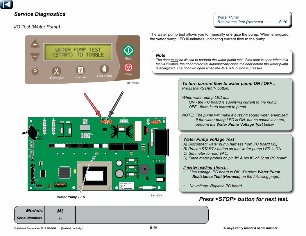
To turn current flow to water pump ON / OFF... Press the <START> button. When water pump LED is... ON - the PC board is supplying current to the pump. OFF - there is no current to pump.
NOTE: The pump will make a buzzing sound when energized. If the water pump LED is ON, but no sound is heard, perform the Water pump Voltage Test below.
Water pump LEd
Water pump Voltage Test A) Disconnect water pump harness from PC board (J2). B) Press <START> button so that water pump LED is ON. C) Set meter to read VAC. D) Place meter probes on pin #1 & pin #2 of J2 on PC board. If meter reading shows...• Line voltage: PC board is OK. (Perform Water pump Resistance Test (harness) on the following page).
• No voltage: Replace PC board.
press <sTOp> button for next test.
service diagnostics
I/O Test (Water Pump)
NoteThe door must be closed to perform the water pump test. If the door is open when this test is initiated, the door motor will automatically close the door before the water pump is energized. The door will open when the <STOP> button is pressed.
Thewaterpumptestallowsyoutomanuallyenergizethepump.Whenenergized,thewaterpumpLEDilluminates,indicatingcurrentflowtothepump.
SA125900i

B-10© Midmark Corporation 2010 SF-1889 Always verify model & serial number
Models:Serial Numbers:
[Revised: mo/dd/yr]
SA126600i
Water Pump Resistance Test (Direct) ..................B-11
M3all
service diagnostics
I/O Test (Water Pump - continued)
Water pump Resistance Test (harness)A) Disconnect water pump harness from PC board (J2). B) Set meter to read ohms (Ω). C) Place meter probes on pump harness pins as shown. You must test harness with probes in both positions shown. (Note the color of the meter probes & their positions in each illustration. This is critical to achieve proper reading).
If meter reading shows...• 200 to 400 Ω: Check Test position #2. • out of range: Perform Water pump Resistance Test (direct) on the following page.
If meter reading shows...• OL: Pump & harness are OK. • out of range: Perform Water pump Resistance Test (direct) on the following page.
Test position #1
blue Wire
brown Wire
Red Meter probe
Test position #2
black Meter probe
blue Wire
brown Wire
Red Meter probe
black Meter probe

B-11© Midmark Corporation 2010 SF-1889 Always verify model & serial number
Models:Serial Numbers:
[Revised: mo/dd/yr]
SA127100i
M3all
service diagnostics
I/O Test (Water Pump - continued)
Water pump harness
Water Pump Exploded View / Part Numbers ..........E-7 Water Pump Replacement ...................003-1777-00 Water Pump Assy. Replacement ...................003-1785-00
Water pump Resistance Test (direct)A) Remove screw, then disconnect water pump harness from pump. B) Set meter to read ohms (Ω). C) Place meter probes on pump terminals as shown.
If meter reading shows... 115 VAc Models• 20 to 40 Ω: Pump is OK - replace harness. • out of range: Replace pump. 230 VAc Models • 130 to 150 Ω: Pump is OK - replace harness • out of range: Replace pump.

B-12© Midmark Corporation 2010 SF-1889 Always verify model & serial number
Models:Serial Numbers:
[Revised: mo/dd/yr]
SA1753i
M3all
service diagnostics
Water Pump Priming Instructions
SA125900i
To prime The Water pump...A) Check that reservoir has been filled with distilled water. B) With top cover removed, go into Service Diagnostics. C) Toggle to the Water Pump Test display screen. D) Press <START> button once to energize and prime the water pump, until air is purged from plastic tubing connecting water pump to the boiler. E) Press <START> again to de energize water pump.
Note: Do not energize water pump for more then 20 seconds at a time.
boiler
Water pump
plastic Tubing
WARNING This operation requires the top cover to be removed while power is connected to the unit. use caution when performing this procedure.
NoteThe door will automatically close before the water pump will begin to run.
NoteThe pump should discharge approximately 3.25 ounces water every five seconds.

B-13© Midmark Corporation 2010 SF-1889 Always verify model & serial number
Models:Serial Numbers:
[Revised: mo/dd/yr]
J7 J8
F1
F2
J5J4J3J2
+5VDC*
1
2
3
2
1
J10
J6
J9
J11
J13
J15
J17
1
2
3
4
J18
015-2040-00Rev AS/N xxxxxxxx
SA126004i
Boiler Voltage Test ...........................B-14
M3all
Temperature display screen
service diagnostics
I/O Test (Boiler)
Theboilertestallowsyoutomanuallyenergizetheboilerfor15secondincrements. TherearetwoboilerLEDsthatilluminatetoindicatecurrentflowtotheboiler.
boiler LEds (2)
To turn current flow to boiler ON / OFF... Press the <START> button. When the two boiler LEDs are... ON - the PC board is supplying current to the boiler. OFF - there is no current to boiler.
To verify proper operation... When the two boiler LEDs turn off (after approx. 15 seconds), press the <STOP> button to advance to the Temperature Display Screen. The internal temperature of the boiler is shown as "BOIL". If the display does not reflect an increase in temperature, perform the boiler Voltage Test on the following page.
press <sTOp> button as necessary to advance to desired test.
SA125900i

B-14© Midmark Corporation 2010 SF-1889 Always verify model & serial number
Models:Serial Numbers:
[Revised: mo/dd/yr]
SA126301i
M3all
service diagnostics
I/O Test (Boiler - continued)
Boiler Exploded View / Part Numbers ..........E-6 Boiler Replacement ............003-1776-00 Boiler O-Ring Replacement ...................003-1779-00 Boiler Assy Replacement ...003-1780-00
boiler Voltage Test A) Press <START> button so that boiler LEDs are ON. B) Set meter to read VAC. C) Place meter probes on boiler terminals. If meter reading shows...• Line voltage: PC board is OK. (Perform boiler Resistance Test).
• No voltage: Replace PC board.
boiler Resistance Test A) Tag & disconnect two wires from boiler. B) Set meter to read ohms (Ω). C) Place meter probes on boiler terminals.
If meter reading shows... 115 VAc Models• 9.8 to 10.8 Ω: Boiler is OK. • out of range: Replace boiler. 230 VAc Models • 39.1 to 43.3 Ω: Boiler is OK. • out of range: Replace boiler.
SA126300i

B-15© Midmark Corporation 2010 SF-1889 Always verify model & serial number
Models:Serial Numbers:
[Revised: 11/1/12]
SA126005i
J7 J8
F1
F2
J5J4J3J2
+5VDC*
1
2
3
2
1
J10
J6
J9
J11
J13
J15
J17
1
2
3
4
J18
015-2040-00Rev AS/N xxxxxxxx
M3all
Dry Heater Resistance Test .............B-16service diagnostics
I/O Test (Dry Heaters #1 & #2)
press <sTOp> button for next test.
To turn current flow to dry heater ON / OFF... Press the <START> button. When the dry heater LED is... ON - the PC board is supplying current to that dry heater. OFF - there is no current to dry heater.
To verify proper operation... When the dry heater LED turns off (after approx. 15 seconds), press the <STOP> button to advance to the Temperature Display Screen. The temperature of the dry heater #1 is shown as "DH1". If the display does not reflect an increase in temperature, perform the dry heater Voltage Test below.
dry heater Voltage Test A) Disconnect dry heater harness from PC board (J7 / J8). B) Press <START> button so that dry heater LED is ON. C) Set meter to read VAC. D) Place meter probes on top two pins of J7 or J8 on PC board. If meter reading shows...• Line voltage and voltage drops to zero after 15 seconds: PC board is OK. (Perform dry heater Resistance Test on following page).
• No voltage or voltage doesn't drop to zero after 15 seconds: Replace PC board.
J7 (Dry Heater #1)
J8 (Dry Heater #2)
dry heater #2 LEd dry heater #1 LEd
SA125900i
Thedryheatertestallowsyoutomanuallyenergizeeachofthetwodryheaters independentlyfor15secondincrements.ThereisaseparateLEDforeachheater thatilluminatestoindicatecurrentflowtothatheater.
Temperature display screen

B-16© Midmark Corporation 2010 SF-1889 Always verify model & serial number
Models:Serial Numbers:
[Revised: mo/dd/yr]
SA126400i
M3all
service diagnostics
I/O Test (Dry Heaters #1 & #2 - continued)
dry heater Resistance Test (Allow unit to cool before performing this test)A) Disconnect dry heater wire harness from PC board (J7 / J8). B) Set meter to read ohms (Ω). C) Place meter probes on wire harness pins as shown. (Note: Check resistance at all three test points shown)
If meter reading shows... 115 VAc Models• 68 to 80 Ω: Test #1 is OK. • out of range: Contact Midmark Technical Service. 230 VAc Models • 273 to 317 Ω: Test #1 is OK. • out of range: Contact Midmark Technical Service.
If meter reading shows...• 0 Ω: Test #2 is OK. • OL or >0: Contact Midmark Technical Service.
If meter reading shows...• 1.05 to 1.1 kΩ: Test #3 is OK. • OL or 0 Ω: Contact Midmark Technical Service.
Test point #1
Test point #2
Test point #3
bluebrown
White
White
brownRed

B-17© Midmark Corporation 2010 SF-1889 Always verify model & serial number
Models:Serial Numbers:
[Revised: mo/dd/yr]
J7 J8
F1
F2
J5J4J3J2
+5VDC*
1
2
3
2
1
J10
J6
J9
J11
J13
J15
J17
1
2
3
4
J18
015-2040-00Rev AS/N xxxxxxxx
SA126006i
M3all
service diagnostics
I/O Test (Condensation Heater)
Condensation Heater Resistance Test ...............................B-18
Thistestallowsyoutomanuallyenergizethecondensationheater. ThecondensationheaterLEDilluminatestoindicatecurrentflowtotheheater.
To turn current flow to condensation heater ON / OFF... Press the <START> button. When the condensation heater LED is... ON - the PC board is supplying current to the heater. OFF - there is no current to heater.
condensation heater Voltage Test A) Disconnect heater harness from PC board (J5). B) Press <START> button so that heater LED is ON. C) Set meter to read VAC. D) Place meter probes on pins of J5 on PC board. If meter reading shows...• Line voltage: PC board is OK. (Perform cond. heater Resistance Test on following page).
• No voltage: Replace PC board.
press <sTOp> button for next test.
To verify proper operation... After the heater has been ON for approx. 1 minute, touch the front panel above the chamber. This area should feel warm. If the panel does not feel warm, perform the condensation heater Voltage Test.
condensation heater LEd
SA125900i

B-18© Midmark Corporation 2010 SF-1889 Always verify model & serial number
Models:Serial Numbers:
[Revised: mo/dd/yr]
M3all
service diagnostics
I/O Test (Condensation Heater - continued)
Condensation Heater Exploded View / Part Numbers ..........E-3
condensation heater Resistance TestA) Disconnect cond. heater wire harness from PC board (J5). B) Set meter to read ohms (Ω). C) Place meter probes on wire harness pins as shown.
If meter reading shows... 115 VAc Models• 716 to 727 Ω: Test #1 is OK. • out of range: Replace Condensation Heater. 230 VAc Models • 2736 to 3168 Ω: Test #1 is OK. • out of range: Replace Condensation Heater.
SA126500i

B-19© Midmark Corporation 2010 SF-1889 Always verify model & serial number
Models:Serial Numbers:
[Revised: mo/dd/yr]
SA126800i
M3all
service diagnostics
I/O Test (Tray / Door Position Switch Display Screen)
NoteTo ensure accurate readings, the door / tray assembly must be positioned so the tray switch is tripped (CLSD).
ThisscreenshowsthestatusoftheTraySwitch(TRAY),ClawSwitch(CLAW),DoorOpenSwitch(OPEN),&theDoorClosedSwitch(CLOSE). Thestatusoftheswitchisshowndirectlybelowtheswitchdisplay.Thestatus(CLSD / OPEN)shouldaccuratelyreflectthecurrentpositionofthatswitch. Theswitchescanbemanuallytripped/untrippedtoverifythereadingiscorrect.
Example: This display shows that the Tray Switch (TRAY) is closed (CLSD). door closedswitch
door clawswitch
Tray switch
door Openswitch
press <sTOp> button for next test.
SA125900i

B-20© Midmark Corporation 2010 SF-1889 Always verify model & serial number
Models:Serial Numbers:
[Revised: mo/dd/yr]
M3all
service diagnostics
I/O Test (Chamber Pressure Display Screen)
Thisscreenshowstheamountofpressurecurrentlyinthechamber.Withthedooropen,thedisplayshouldread"0.1PSI".
press <sTOp> button for next test.
SA125900i

B-21© Midmark Corporation 2010 SF-1889 Always verify model & serial number
Models:Serial Numbers:
[Revised: mo/dd/yr]
M3all
service diagnostics
I/O Test (Temperature Display Screen)
Thisscreendisplaysthetemperatureinsidethechamber(CHAM),insidetheboiler(BOIL),andforthetwodryheaters(DH1 & DH2).
press <sTOp> button for next test.
SA125900i

B-22© Midmark Corporation 2010 SF-1889 Always verify model & serial number
Models:Serial Numbers:
[Revised: mo/dd/yr]
M3all
service diagnostics
I/O Test (Water Level / External Tank Sensor Display Screen)
Thisscreenshowsthestatusofthewaterlevelsensorinthereservoir (WATER LVL),&thesensorsintheexternalcondensingtank(EXT TANK). Note: The sensor status is displayed in a numeric code. Refer to the illustration below for explanation of the numeric readout.
press <sTOp> button to return to beginning of I/O Test.
Water Level sensor (reservoir)# code description1023 WaterlevelOK
0 Lowwater
External Tank sensor# code description> 950 Tankdisconnected
910 - 920 WaterlevelOK< 750 Tankisfull
SA125900i

B-23© Midmark Corporation 2010 SF-1889 Always verify model & serial number
Models:Serial Numbers:
[Revised: mo/dd/yr]
M3all
service diagnostics
Error Code Display Screen
Thisscreenshowsthelastfiveerrorcodesstoredintheunit.
Note1: indicates the most recent error code. 5: indicates the oldest.
To erase all five error codes from memory... Press <START> button. To retain the error codes in memory... Press <STOP> button.
SA125900i

B-24© Midmark Corporation 2010 SF-1889 Always verify model & serial number
Models:Serial Numbers:
[Revised: mo/dd/yr]
M3all
service diagnostics
Key Test Display Screen
To test the functionality of the touch pad... Press <START> button. (When the designated button is pressed, you will hear a single "beep" and the test will advance to the next button. This indicates the button is functioning properly). Continue for all remaining buttons.
SA125900i

B-25© Midmark Corporation 2010 SF-1889 Always verify model & serial number
Models:Serial Numbers:
[Revised: mo/dd/yr]
M3all
service diagnostics
Five Point Leak Check
point 1: door / Tray Gasket.A) Check for water or steam leakage from around Door / Tray.B) Clean or replace Door / Tray Gasket.
point 2: Vent Valve.A) Check plastic tube connecting unit to the external condensing tank for a flow of steam and hot water in between vent valve operations.B) Clean or replace Vent Valve.
point 3: pressure Relief Valve.A) Check for water or steam leakage from under the back left hand corner of sterilizer.B) Pop off and re-seat, or replace Pressure Relief Valve..
point 4: pressure sensor Tubing.A) Check for water or steam leakage onto main PC board where pressure sensor tubing attaches to pressure transducer.B) Reattach or replace Pressure Sensor Tubing.
point 5: Fittings.A) Check all plumbing fitting connections for leakage.B) Tighten or replace fittings.

B-26© Midmark Corporation 2010 SF-1889 Always verify model & serial number
Models:Serial Numbers:
[Revised: mo/dd/yr]
SA1754i
J7 J8
+5VDC*
1
2
3
2
1
J10
J11
J13
J15
J17
1
2
3
4
J18
M3all
service diagnostics
Temperature Sensor Resistance Test
NoteThe sensor(s) must be tested at room temperature.
chamber Temperature sensor Test...A) Disconnect sensor harness from J11 on PC board. B) Set meter to 2k ohms (Ω). C) Place meter probes on the red and white wires. The acceptable reading is 1.07 to 1.1 ohms (Ω). D) Clean sensor with mild soap and distilled water.
boiler Temperature sensor Test...A) Disconnect sensor harness from J10 on PC board. B) Set meter to 2k ohms (Ω). C) Place meter probes on the red and white wires. The acceptable reading is 1.07 to 1.1 ohms (Ω).
White
Red
J10 boiler
J11 chamber

B-27© Midmark Corporation 2010 SF-1889 Always verify model & serial number
Models:Serial Numbers:
[Revised: mo/dd/yr]
M3all
service diagnostics
Boiler Overheat Thermostat
The thermostat is located under the boiler assembly. A manual reset button is located in between the terminals of the thermostat.
Reset button (press to reset)
Thermostat (trips open at 375°)
With switch ‘untripped’...Meter Reading Required ActionAny resistance
readingSwitchisgood.
OL Replaceswitch
Step 1: Disconnectwiresfromthermostat.
NoteOverheat Thermostat must be tested at room temperature.
Step 2: Placemeterprobesonthermostatterminals [Set meter to ohms (Ω)]
C-1© Midmark Corporation 2010 SF-1889 [Revised: mo/dd/yr]
Sec
tion
CAccess procedures
Top Cover Removal / Installation ........................C-2

C-2© Midmark Corporation 2010 SF-1889 Always verify model & serial number
Models:Serial Numbers:
SA1061-01i
[Revised: 04-05-2011]
SA102900i
M3all
Top cover
Removal / Installation
Exploded View / Part Numbers Ritter models ..................................E-2 Midmark models .............................E-2
WARNING power unit off and unplug from outlet to prevent electrical shock.
step 1: RemovalA) Power unit off by using switch.B) Unplug unit from wall outlet.
step 2: RemovalRemove four screws (two from back and one from each side) and slide cover back and up.
step 1: InstallationPlacecoveronsterilizerandslideforward intoposition,andattachwithtwoscrews.
step 2: InstallationPlug unit into dedicated outlet and power on.

D-1© Midmark Corporation 2010 SF-1889 [Revised: mo/dd/yr]
Sec
tion
DWiring diagrams

D-2© Midmark Corporation 2010 SF-1889 Always verify model & serial number
Models:Serial Numbers:
[Revised: 2/6/12]
SA109303i
Wire
Harness From: To: Part Number
Ref.Page
A MainPCB(J1) DoorMotor PartofDoor
MotorAssy. E-5**
B MainPCB(J2) Pump 002-1085-00 E-7**
C MainPCB(J3)
BoilerThermostat 015-2056-00 E-6***
D MainPCB(J4) VentValve 015-2057-00 E-7**
E MainPCB(J5)
CondensingHeater
PartofCondensing
HeaterE-3**
F MainPCB(J7)
ChamberSurfaceHeater
NotServiceable **
G MainPCB(J8)
ChamberSurfaceHeater
NotServiceable **
H MainPCB(J9)
SwitchHarnessAssembly 002-1088-00 E-4*
E-5*
I MainPCB(J10)
BoilerTemperature
Sensor
PartofBoilerTemperature
SensorsE-6***
J MainPCB(J11)
ChamberTemperature
Sensor
PartofChamber
TemperatureSensor
E-10***
K MainPCB(J13)
Reservoir WaterLevel Sensor
PartoffReservoir Water
Level SensorE-8***
L MainPCB(J14) PrinterPort 015-2102-00 E-14***
M MainPCB(J15) DisplayPort Partof
DisplayPCB E-3***
N MainPCB(J16)
ExternalCondensingTank 015-2089-00 E-13***
O MainPCB(J17)
SerialCommunication NotSupplied
P MainPCB(J18)
ProgramingPort NotSupplied
Q ApplianceInlet
BaseAssembly 015-2103-00
M3all
Wiring diagrams
(*) Denotesconstantvoltage. (**) Denotesvoltagepresentonlyduring componentoperation. (***) DenotesrectifiedDCvoltagepresent duringoperation. Alwaysdisconnectplugconnector whencheckingvoltage.
Fuses: 115VACmodels; F1..........15amp,250V,FastActing,1/4"x11/4" F2..............0.25amp,250V,SloBlo,1/4"x11/4"230VACmodels: F1..........8amp,250V,FastActing,5mmx20mm F2..........0.125amp,250V,SloBlo,5mmx20mm

E-1© Midmark Corporation 2010 SF-1889 [Revised: mo/dd/yr]
Sec
tion
EExploded Views & parts Lists
XXX-XXXX-XX
XXX-XXXX-XX
XXX-XXXX-XX
M3: (-001, -002, -003, -004) ..............E-2

E-2© Midmark Corporation 2010 SF-1889 Always verify model & serial number
Models:Serial Numbers:
[Revised: mo/dd/yr]
SA1751i
M3 (-001 / -002 / -003 / -004)
M3all
* Indicates multiple pages due to a serial number break for the parts illustration.
Main Components .............................E-4
Plumbing and Tubing Components ....................................E-11
Troubleshooting .................................A-1Testing / Repair .................................B-1 Access Procedures............................C-1 Wiring Diagrams ................................D-1 Exploded Views / Part Numbers ........E-1
M3 Label Location ...........................E-15M3 Shipping Packaging ...................E-14
M3 Door / Tray Accessory (9A402xxx) ......................................E-12
Main Enclosure ..................................E-3
Door / Tray Latch Mechanism ........................................E-5
Switch Harness Assembly ...............E-10
Pressure Interlock Assembly ...........................................E-5
M3 Boiler Assembly ...........................E-6
M3 Pump / Solenoid Assembly ...........................................E-7
M3 Reservoir Assembly ...........................................E-8
M3 PCB Assembly .............................E-9 includes: power switch and outlet
M3 External Tank .............................E-13

E-3© Midmark Corporation 2010 SF-1889 Always verify model & serial number
Models:Serial Numbers:
SA1750-01i
[Rev. 11/14/12]
M3 (all)V792976 thru V1061864
Troubleshooting .................................A-1Testing / Repair .................................B-1 Access Procedures............................C-1 Wiring Diagrams ................................D-1 Exploded Views / Part Numbers ........E-1
Main EnclosureItem Description Qty.
1 FillFunnelLid 12 Screw(#10-16 x 3/4", self drilling) 93 TopCoverWeldment 14 ExternalToothLockWasher(#10) 25 TrimLock 16 PlasticFoot 47 HoseClip 18 PopRivet(.125" x .265") 19 DisplayNoAccessPlate 1
10Front Cover (includes items 11 thru 14) a) Midmark b) Ritter
1
11 •MembraneSwitch 112 •UsersInformation 113 •AccessDoor 114 •DisplayPCBAssembly(includes item 15) 115 ••RibbonCable 116 DrainTubeAssembly 1
17CondensateHeaterAssemblya) 115 volt)b) 230 volt)
1
18 Screw(M4 x 12mm) 2
053-1602-00-376 13
6 016-0523-03
2
9 050-6577-00
15 015-1550-03
7 053-0388-01
8 042-0010-11
2
a) 029-4829-00 17b) 029-4829-01
5 016-0140-05
2
4 045-0001-31
053-1631-00-376 1
029-3819-00 16
029-3935-00 12
015-1550-02 14
040-0010-163 2
030-1605-00-253 3
002-1083-00 11
a) 002-1485-00 10b) 002-1485-01
042-0184-01 18
2

E-3.1© Midmark Corporation 2010 SF-1889 Always verify model & serial number
Models:Serial Numbers:
[Revised: [11/14/12]
M3 (all)V1061865 thru Present
Troubleshooting .................................A-1Testing / Repair .................................B-1 Access Procedures............................C-1 Wiring Diagrams ................................D-1 Exploded Views / Part Numbers ........E-1
Main EnclosureItem Description Qty.
1 FillFunnelLid 12 Screw(#10-16 x 3/4”, self drilling) 93 TopCoverWeldment 14 ExternalToothLockWasher(#10) 25 TrimLock 16 PlasticFoot 47 HoseClip 18 PopRivet(.125" x .265") 19 DisplayPCBAssembly(includes item 10) 110 •RibbonCable 111 NylonHexNut(#10-24) 412 PCBCover 113 NylonScrew(#10-24 x 3/4”) 214 Access Door 115 UsersInformation 1
16Front Cover (includes item 17) a) Midmark b) Ritter
1
17 •MembraneSwitch 118 DrainTubeAssembly 1
19CondensateHeaterAssemblya) 115 volt)b) 230 volt)
1
20 Screw(M4 x 12mm) 2
053-1602-00-376 14
6 016-0523-03
2
7 053-0388-01
8 042-0010-11
2
a) 029-4829-00 19b) 029-4829-01
5 016-0140-05
2
4 045-0001-31
053-1631-00-376 1
029-3819-00 18
029-3935-00 15
040-0010-163 2
030-1605-00-253 3
002-1083-00 17
a) 002-1082-00 16b) 002-1082-01
042-0184-01 20
2
11
9 015-1550-02
10 015-1550-03
11 041-0010-15
12 053-2222-00-216040-0010-177 13

E4© Midmark Corporation 2010 SF-1889 Always verify model & serial number
Models:Serial Numbers:
[Rev. 4/10]
SA1749i
M3 (all)V792976 thru Present
Troubleshooting .................................A-1Testing / Repair .................................B-1 Access Procedures............................C-1 Wiring Diagrams ................................D-1 Exploded Views / Part Numbers ........E-1
Main componentsItem Description Qty.
1 SwitchSpring 12 MaroonCableTie,HighTemp 13 TraySwitchBracketAssembly 14 Screw (#6-32 x 7/16") 15 KepsNut(#10-24) 46 Referto: Switch Harness Assembly Ref7 Chamberassembly(not serviceable) Ref8 Referto: Boiler Assembly Ref
9
Cordset: a) 115 volt [North American]b) 230 volt [United Kingdom]c) 230 volt [Austrailian]d) 230 volt [Israeli]e) 230 volt [North American]
1
10 Referto:Reservoir Assembly Ref11 Referto:Pump Solenoid Assembly Ref12 Screw(#10-16 x 3/4") 313 Referto:PCB Assembly Ref14 Screw (M4 x 12mm) 115 PopRivet 216 BaseGusset 117 Screw (#10-32 x 3/8") 618 BaseAssembly 1
9 a) 015-0640-00 b) 9A152-002 c) 9A152-005 d) 9A152-006 e) 9A152-008
1011
8
13
12 040-0010-163
5 041-0010-04
14 042-0184-01
15 042-0010-11
16 050-6676-0017 040-0010-74
1 058-0012-006
3 029-4303-00
5
17
4 040-0006-44
2 015-0013-05
7
029-3683-00 18

E5© Midmark Corporation 2010 SF-1889 Always verify model & serial number
Models:Serial Numbers:
[Revised: 01-27-2011]
SA1744i
M3 (all)V792976 thru V811649
Troubleshooting .................................A-1Testing / Repair .................................B-1 Access Procedures............................C-1 Wiring Diagrams ................................D-1 Exploded Views / Part Numbers ........E-1
door / Tray Latch MechanismItem Description Qty.
1 PressureInterlockAssembly(Use 002-1258-00) 12 ShoulderScrew(1/4" x 3/8") 13 PressureLockBracket 14 Washer(#10) 15 CotterPin (1.438) 16 Flange Bearing 17 StemBumper 1
8MotorAssemblya) 115 voltb) 230 volt
1
9 PivotPin 310 ClawConnectingRod 211 DoorOpenBracket 112 SwitchMountingBracket 113 ClawAdjustmentPlate 114 DoorOpenPivotBracketAssembly 115 MotorConnectingFork 116 MotorConnectingRod 117 MotorMountingBracket 1
18 Referto: Switch Harness Assembly Ref
19 Screw(#8-32 x 3/8") 220 Screw(#10-32 x 3/8" hex head) 221 Screw (#10-32 x 3/8" pan head) AR
11 050-6575-00
10 057-0857-00
7 053-0001-00
6 016-0131-18
4 045-0001-42
3 050-7394-00
2 042-0014-21
5 042-0004-00
9
20 040-0010-171
19 040-0008-04
18
029-3810-00 17
057-0860-00 16
050-6826-00 15
9
21
10
050-7346-01 12
21
9 016-1018-02
8 a) 002-1054-00 b) 002-1054-01
20
050-6760-00 13
14 029-3883-00
18
18
040-0010-74 21
21
1 N.L.A.
N.L.A. Denotes "No Longer Available"

© Midmark Corporation 200x SF-xxxx
Models:Serial Numbers:
Always verify model & serial number
SA1746i
[Revised: 01-27-2011] E-5.1
M3 (all)V811650 thru Present
Troubleshooting .................................A-1Testing / Repair .................................B-1 Access Procedures............................C-1 Wiring Diagrams ................................D-1 Exploded Views / Part Numbers ........E-1
door / Tray Latch MechanismItem Description Qty.
1 PressureInterlockAssembly 12 ShoulderScrew(1/4" x 3/8") 13 PressureLockBracket 14 Washer(#10) 15 CotterPin (1.438) 16 Flange Bearing 17 StemBumper 1
8MotorAssemblya) 115 voltb) 230 volt
1
9 PivotPin 310 ClawConnectingRod 211 DoorOpenBracket 112 SwitchMountingBracket 113 ClawAdjustmentPlate 114 DoorOpenPivotBracketAssembly 115 MotorConnectingFork 116 MotorConnectingRod 117 MotorMountingBracket 1
18 Referto: Switch Harness Assembly Ref
19 Screw(#8-32 x 3/8") 220 Screw(#10-32 x 3/8" hex head) 221 Screw (#10-32 x 3/8" pan head) AR
11 050-6575-00
10 057-0857-00
7 053-0001-00
6 016-0131-18
4 045-0001-42
3 050-7394-00
2 042-0014-21
5 042-0004-00
9
20 040-0010-171
19 040-0008-04
18
029-3810-00 17
057-0860-00 16
050-6826-00 15
9
21
10
050-7346-01 12
21
9 016-1018-02
8 a) 002-1054-00 b) 002-1054-01
20
050-6760-00 13
14 029-3883-00
18
18
040-0010-74 21
21
1 002-1258-00

E-6© Midmark Corporation 2010 SF-1889 Always verify model & serial number
Models:Serial Numbers:
[Revised: 6/27/2011]
SA102300i
M3 (all)V792976 thru Present
Troubleshooting .................................A-1Testing / Repair .................................B-1 Access Procedures............................C-1 Wiring Diagrams ................................D-1 Exploded Views / Part Numbers ........E-1
boiler AssemblyItem Description Qty.
1BoilerAssy.Kit(includes items 2 thru 8)a) 115 voltb) 230 volt
1
2 •40PSIPressureReliefValveKit 13 • MaleElbow (1/4" OD x 1/8" NPT) 24 •Screw(#10-24 x 1/2" stainless steel) 45 •BoilerCap,Coated 1
6•SteamBoilerKit(incl. item 11) a) 115 volt b) 230 volt
1
7 •SteamBoilerO-ringKit 18 • AdapterTee (1/4 OD x 1/8' NPT) 19 TemperatureSensor,Boiler 110 Screw(#10-16 x 3/4") 211 ManualResetThermostatKit-375° F 112 BoilerMountingBracket 113 PRVEnclosure-RH 114 PRVEnclosure-LH 1
015-1810-00 14
014-0184-00 3
014-0484-00 8
002-1080-00 7
040-0010-163 10
015-2046-00 9
12 050-6728-00
11 002-1089-00
5 020-0275-02
4 121980-5
13 015-1811-00
2 002-1084-00
1 a) 002-1081-00 b) 002-1081-01
a) 002-1052-00 6b) 002-1052-02
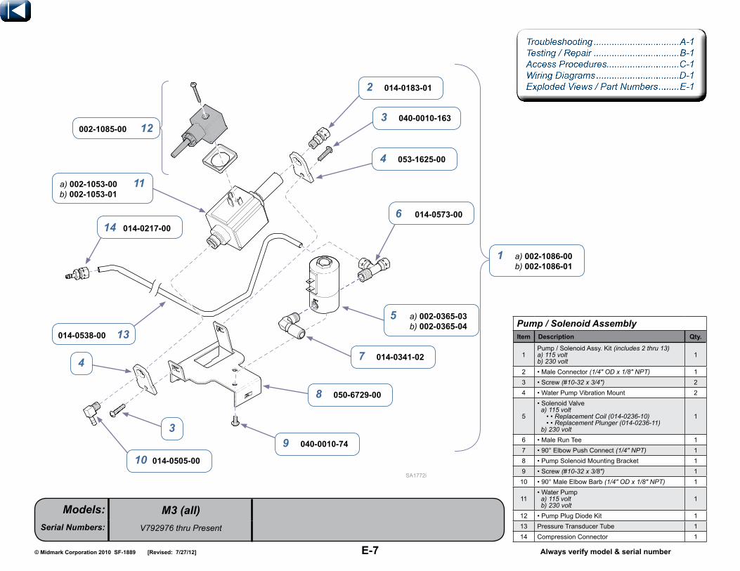
E-7© Midmark Corporation 2010 SF-1889 Always verify model & serial number
Models:Serial Numbers:
[Revised: 7/27/12]
M3 (all)V792976 thru Present
Troubleshooting .................................A-1Testing / Repair .................................B-1 Access Procedures............................C-1 Wiring Diagrams ................................D-1 Exploded Views / Part Numbers ........E-1
pump / solenoid AssemblyItem Description Qty.
1Pump/SolenoidAssy.Kit(includes 2 thru 13) a) 115 voltb) 230 volt
1
2 •MaleConnector(1/4" OD x 1/8" NPT) 13 • Screw(#10-32 x 3/4") 24 • WaterPumpVibrationMount 2
5
•SolenoidValve a) 115 volt • • Replacement Coil (014-0236-10) • • Replacement Plunger (014-0236-11) b) 230 volt
1
6 •MaleRunTee 17 •90°ElbowPushConnect(1/4" NPT) 18 •PumpSolenoidMountingBracket 19 •Screw(#10-32 x 3/8") 110 •90°MaleElbowBarb (1/4" OD x 1/8" NPT) 1
11•WaterPump a) 115 volt b) 230 volt
1
12 •PumpPlugDiodeKit 113 PressureTransducerTube 114 CompressionConnector 1
1 a) 002-1086-00 b) 002-1086-01
2 014-0183-01
3 040-0010-163
6 014-0573-00
7 014-0341-02
8 050-6729-00
9 040-0010-74
3
10 014-0505-00
014-0538-00 13
14 014-0217-00
a) 002-1053-00 11b) 002-1053-01
002-1085-00 12
4 053-1625-00
5 a) 002-0365-03 b) 002-0365-04
4

E-8© Midmark Corporation 2010 SF-1889 Always verify model & serial number
Models:Serial Numbers:
[Revised: 01-27-2011]
SA102501i
M3 (all)V792976 thru Present
Troubleshooting .................................A-1Testing / Repair .................................B-1 Access Procedures............................C-1 Wiring Diagrams ................................D-1 Exploded Views / Part Numbers ........E-1
Reservoir AssemblyItem Description Qty.
1 ReservoirAssembly (includes 2 thru 13) 12 •FillFunnel 13 • SteamBoilerO-ringKit 14 •ReservoirLid 15 •CouplingWasher 16 •SideMountFloatAssembly (includes 7 thru 8) 17 • • PanelMountGasket 18 ••PanelMountNut 19 • 1/4"ODBulkheadUnionBarb (includes nut) 110 • BulkheadFittingWasher 111 • QuickDisconnectCoupling (includes item 12) 112 • • NickleBrassPlatedNut 113 •ReservoirTank 1
2 053-1630-00-376
4 053-1629-00-376
12 053-0990-02
13 053-1628-00-376
6 015-2204-00
015-2204-02 8
015-2204-01 7
9 014-0504-00
1 029-3753-00
10 053-0975-03
11 053-0990-00
053-0990-03 5
002-1080-00 3
9

E-9© Midmark Corporation 2010 SF-1889 Always verify model & serial number
Models:Serial Numbers:
[Revised: 01-27-2011]
+
ON
12
34
56
78
ONON
ONON
ONON
ON
3
2
1
3
2
1
3
1
2
SA105200i
M3 (all)V792976 thru Present
Troubleshooting .................................A-1Testing / Repair .................................B-1 Access Procedures............................C-1 Wiring Diagrams ................................D-1 Exploded Views / Part Numbers ........E-1
pc board AssemblyItem Description Qty.
1PCBoardAssemblyKit (includes items 2 thru 6) a) 115 volt b) 230 volt
1
2•SterilizerControlAssemblyKit (includes 2 thru 6) a) 115 volt b) 230 volt
1
3••F1Fuse a) 15A (115 volt) b)8A(230 volt)
1
4••F2Fuse a) .25A (115 volt)b).125A(230 volt)
1
5 •PCBDualSnap-onStandoff 76 • PCBMountingBracket 1
1 a) 002-1051-00 b) 002-1051-01
a) 002-1051-00 2b) 002-1051-01
a) 015-0346-07 3b) 015-0346-11
a) 015-0346-10 4b) 015-0346-14
053-1455-00 5
050-6592-00-253 6

E-10© Midmark Corporation 2010 SF-1889 Always verify model & serial number
Models:Serial Numbers:
[Revised: mo/dd/yr]
SA1748i
Troubleshooting .................................A-1Testing / Repair .................................B-1 Access Procedures............................C-1 Wiring Diagrams ................................D-1 Exploded Views / Part Numbers ........E-1
switch harness AssemblyItem Description Qty.
1 •SwitchHarnessKit(includesitems2thru4) [includes harness & four switches] 1
2 •Insulator 83 •SwitchActuator 44 •Screw 85 Referto:Main Components Ref6 Referto:Main Components Ref
040-0002-09 4053-1348-00 2
3 050-6223-00
M3 (all)V792976 thru Present
5
6 1 002-1088-00

E-11© Midmark Corporation 2010 SF-1889 Always verify model & serial number
Models:Serial Numbers:
[Revised: 5/3/12]
Troubleshooting .................................A-1Testing / Repair .................................B-1 Access Procedures............................C-1 Wiring Diagrams ................................D-1 Exploded Views / Part Numbers ........E-1
plumbing & Tubing componentsItem Description Qty.
1 Referto: Boiler Assembly Ref2 BrassTubeSupport(1/4") 23 Tube,PumptoBoiler(16" teflon) 14 Tube,BoilertoLiner(copper) 15 Referto: Pump / Solenoid Assembly Ref
6 Tube,ReservoirtoPump(1/8" x 3/8" x 3.00" [neoprene]) 1
7 Referto: External Tank Assembly Ref8 MaroonCableTie,HighTemp 39 TransducerTube(1/8" x 3/8" x 4.00" [neoprene]) 110 SpringClamp 111 FilterRemovalTool 112 Referto: Reservoir Assembly Ref13 ChamberTemperatureSensor 114 MaleConnector (1/4" OD x 1/8" NPT) 215 CheckValve 116 ChamberAssembly (not serviceable) Ref17 ChamberFilter 118 CableTie 419 TeeFitting 120 Screw (#10-32 x 3/8") 421 Tube (copper) 222 Tube (copper) 1
23 Tube,PressureRelief (1/8" x 3/8" x 5.50" [neoprene]) 1
M3 (all)V792976 thru Present
12 014-0574-00
3 053-0390-05
4 014-0523-00
75
6 053-0404-08
015-0013-05 8
053-0404-09 9
016-1154-00 10
014-0183-01 14
015-2039-01 13
12
016-1095-00 17
015-0017-00 18
040-0010-74 20
014-0202-00 19
014-0524-00 21
014-0639-00 15
053-0613-05 23
16
21
014-0206-00 22
11 050-7068-00

E-12© Midmark Corporation 2010 SF-1889 Always verify model & serial number
Models:Serial Numbers:
[Revised: 01-27-2011]
SA105800i
M3 (all)V817423 thru Present
Troubleshooting .................................A-1Testing / Repair .................................B-1 Access Procedures............................C-1 Wiring Diagrams ................................D-1 Exploded Views / Part Numbers ........E-1
door / Tray Accessory (9A402001)Item Description Qty.
1 DoorTrayAccessory (includes items 2 thru 11) 12 •TopDoorHandle 13 •StainlessSteelWingNut (1/4"-20) 24 •FormedTray 15 •DoorSealGasketKit 16 •DoorWeldment(not serviceable) Ref7 •Bushing/SleeveAssembly 28 • Klipring 29 •BottomDoorHandle 110 •Screw(#10-24 x 5/8") 211 • Screw (#10-24 x 3/8") 2
9A402001 1
2 053-1601-00-376
3 041-0250-22
4 050-6727-00
5 002-1030-00
7 029-4185-00
8 042-0065-02
9 053-1600-00-376
10 040-0010-95
040-0010-75 11
6

E-13© Midmark Corporation 2010 SF-1889 Always verify model & serial number
Models:Serial Numbers:
[Revised: mo/dd/yr]
SA110700i
M3 (all)V818603 thru Present
Troubleshooting .................................A-1Testing / Repair .................................B-1 Access Procedures............................C-1 Wiring Diagrams ................................D-1 Exploded Views / Part Numbers ........E-1
External Tank AssemblyItem Description Qty.
1 ExternalTankAssembly (includes items 2 thru 10) 12 •PlasticBulkheadUnion 1
3 • ExternalTankLidAssembly (includes items 4 thru 7) 1
4 ••StainlesssteelHexNut(#8-32) 45 ••ExternalTankSensorHarness 16 • • ExternalPitcherLid 17 ••ExternalLevelSensor 28 •CondensationCoil 19 •ExternalReservoirPitcher 110 • ExternalTankTubingAssembly 1
002-1031-00 1
3 029-3971-00
057-0869-00 7
2 014-0350-00
4 041-0008-03
5 015-2089-00
4
6 053-1740-00-376
8 014-0502-00
10 029-4147-00 9 053-1739-00-376

E-14© Midmark Corporation 2010 SF-1889 Always verify model & serial number
Models:Serial Numbers:
[Revised: 10/19/11]
M3 (all)all
Troubleshooting .................................A-1Testing / Repair .................................B-1 Access Procedures............................C-1 Wiring Diagrams ................................D-1 Exploded Views / Part Numbers ........E-1
Return shipping packageItem Description Qty.
1 ReturnShippingPackage (includes Items 2 thru 4) 1
2 • M3TopPartitionAssembly 13 • M3PackagingBaseAssembly 14 •M3Carton 1
1 002-1008-00
4 066-1198-00
3 029-5202-00
2 029-5432-00

E-15© Midmark Corporation 2010 SF-1889 Always verify model & serial number
Models:Serial Numbers:
[Revised: mo/dd/yr]
LABORATORY
EQUIPMENT59FM
SA109800i
M3 (all)V792976 thru Present
Troubleshooting .................................A-1Testing / Repair .................................B-1 Access Procedures............................C-1 Wiring Diagrams ................................D-1 Exploded Views / Part Numbers ........E-1
M3 Label LocationItem Description Qty.
1 LargeSerialNumberLabel Ref2 HotSurfaceLabel 13 PatentLabel Ref4 SwitchBoxCautionSticker Ref5 C.U.L.ListingLabel Ref6 SerialNumberIdentificationLabel Ref
6
5
4
3
2 061-0726-00
1

E-16© Midmark Corporation 2010 SF-1889 [Revised: mo/dd/yr]
This page intentionally left blank LEAVE IT IN!


![Sterilizer Manual [h2115]](https://static.fdocuments.in/doc/165x107/577cd0981a28ab9e7892a0b0/sterilizer-manual-h2115.jpg)