Denali R4 Thermoelectric Chiller Manual - Cole-Parmer · Denali R4 Thermoelectric Chiller . Manual...
31
Denali R4 Thermoelectric Chiller Manual (from Solid State Cooling Systems built exclusively for Cole-Parmer) 167 Myers Corners Road, Wappingers Falls NY, 12569 (845)296-1300 email: [email protected] www.sscooling.com
Transcript of Denali R4 Thermoelectric Chiller Manual - Cole-Parmer · Denali R4 Thermoelectric Chiller . Manual...

Denali R4 Thermoelectric Chiller Manual
(from Solid State Cooling Systems built exclusively for Cole-Parmer)
167 Myers Corners Road, Wappingers Falls NY, 12569
(845)296-1300
email: [email protected]
www.sscooling.com

DENALI R4 THERMOELECTRIC CHILLER 52-13371-1
SOLID STATE COOLING SYSTEMS, 167 MYERS CORNERS ROAD, WAPPINGERS FALLS, NY 12590 TELEPHONE: (845) 296-1300 FAX: (845) 296-1303 WEB: WWW.SSCOOLING.COM VERSION E1
2

DENALI R4 THERMOELECTRIC CHILLER
SOLID STATE COOLING SYSTEMS, 167 MYERS CORNERS ROAD, WAPPINGERS FALLS, NY 12590 TELEPHONE: (845) 296-1300 FAX: (845) 296-1303 WEB: WWW.SSCOOLING.COM VERSION E1
TTAABBLLEE OOFF CCOONNTTEENNTTSS
SAFETY PRECAUTIONS AND SYMBOLS _____________________________________________ 2
SECTION 1 _________________________________________________________________________ 3
INTRODUCTION ______________________________________________________________________ 3
SECTION 2 _________________________________________________________________________ 4
SPECIFICATIONS _____________________________________________________________________ 4
SECTION 3 _________________________________________________________________________ 6
HOOK UP __________________________________________________________________________ 6 3.1 Mechanical Installation _________________________________________________________ 7 3.2 Electrical Connections (see figure 3B) ______________________________________________ 7 3.3 Plumbing Connections (see figure 3B) ______________________________________________ 8 3.4 Coolant Fill ___________________________________________________________________ 8
SECTION 4 _________________________________________________________________________ 9
START UP __________________________________________________________________________ 9
SECTION 5 _________________________________________________________________________ 9
OPERATION ________________________________________________________________________ 9 5.1 Simple Operation _____________________________________________________________ 10 5.2 Advanced Operation ___________________________________________________________ 10 5.3 Alarms ______________________________________________________________________ 12 5.4 Drain Procedure ______________________________________________________________ 12
SECTION 6 ________________________________________________________________________ 13
SYSTEM ALARMS/TROUBLESHOOTING ___________________________________________________ 13
SECTION 7 ________________________________________________________________________ 14
USB COMMUNICATIONS _____________________________________________________________ 14
SECTION 8 ________________________________________________________________________ 15
CLEANING YOUR CHILLER ____________________________________________________________ 15
SECTION 9 ________________________________________________________________________ 15
TECHNICAL SUPPORT ________________________________________________________________ 15
SECTION 10 _______________________________________________________________________ 16
MSDS FOR COOLANTS _______________________________________________________________ 16
WARRANTY POLICY ______________________________________________________________ 28

DENALI R4 THERMOELECTRIC CHILLER 52-13371-1
SOLID STATE COOLING SYSTEMS, 167 MYERS CORNERS ROAD, WAPPINGERS FALLS, NY 12590 TELEPHONE: (845) 296-1300 FAX: (845) 296-1303 WEB: WWW.SSCOOLING.COM VERSION E1
1
CE Declaration of Conformity
We: Solid State Cooling Systems 167 Myers Corners Road Wappingers Falls, NY 12590
USA declare under our sole responsibility that the
Denali R4 meets the provisions of the directives: 2004/108/EC EMC Directive 2006/95/EC Low Voltage Directive EN 61326-1: 2006 Emissions and Immunity EN 61000-3-2: 2006 Harmonics Emissions EN 61000-3-3: 2008 Voltage Fluctuations and Flicker EN 61010-1: 3rd Edition Safety Low Voltage Directive Safety requirements for
electrical equipment for measurement, control, and laboratory use.
Lloyd F Wright
Chief Technology Officer
Date
October 22, 2013
DENALI R4 THERMOELECTRIC CHILLER 52-13371-1
SOLID STATE COOLING SYSTEMS, 167 MYERS CORNERS ROAD, WAPPINGERS FALLS, NY 12590 TELEPHONE: (845) 296-1300 FAX: (845) 296-1303 WEB: WWW.SSCOOLING.COM VERSION E1
2
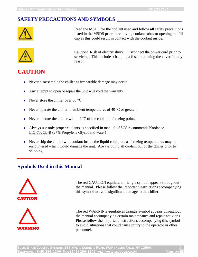
SAFETY PRECAUTIONS AND SYMBOLS _________________________
Read the MSDS for the coolant used and follow all safety precautions
listed in the MSDS prior to removing coolant tubes or opening the fill cap as this could result in contact with the coolant inside.
Caution! Risk of electric shock. Disconnect the power cord prior to
servicing. This includes changing a fuse or opening the cover for any reason.
CCAAUUTTIIOONN
Never disassemble the chiller as irreparable damage may occur.
Any attempt to open or repair the unit will void the warranty
Never store the chiller over 60 °C. Never operate the chiller in ambient temperatures of 40 ºC or greater.
Never operate the chiller within 2 ºC of the coolant’s freezing point.
Always use only proper coolants as specified in manual. SSCS recommends Koolance
LIQ-702CL-B (27% Propylene Glycol and water) Never ship the chiller with coolant inside the liquid cold plate as freezing temperatures may be
encountered which would damage the unit. Always pump all coolant out of the chiller prior to shipping.
Symbols Used in this Manual
The red CAUTION equilateral triangle symbol appears throughout the manual. Please follow the important instructions accompanying this symbol to avoid significant damage to the chiller.
The red WARNING equilateral triangle symbol appears throughout the manual accompanying certain maintenance and repair activities. Please follow the important instructions accompanying this symbol to avoid situations that could cause injury to the operator or other personnel.
CAUTION
WARNING

DENALI R4 THERMOELECTRIC CHILLER 52-13371-1
SOLID STATE COOLING SYSTEMS, 167 MYERS CORNERS ROAD, WAPPINGERS FALLS, NY 12590 TELEPHONE: (845) 296-1300 FAX: (845) 296-1303 WEB: WWW.SSCOOLING.COM VERSION E1
3
Manual
DENALI R4 THERMOELECTRIC CHILLER SECTION 1 INTRODUCTION __________________________________________________
The Denali R4 rack-mount recirculating chiller utilizes thermoelectric technology to deliver 380 Watts of cooling capacity without the use of compressors or refrigerants. With fewer moving parts, the system is highly reliable and energy efficient. The Denali R4 is an excellent choice if you need a versatile chiller which is rack mountable in a standard 19”. The R4 can be used in a wide variety of lab applications, including temperature control of analytical equipment, lasers, low-light CCD cameras, SEMs, baths or other lab equipment. From conception, this chiller has been designed for long life and ease of use. The internal thermoelectric modules have lifetimes greater than 200,000 hours.
PRODUCT

DENALI R4 THERMOELECTRIC CHILLER 52-13371-1
SOLID STATE COOLING SYSTEMS, 167 MYERS CORNERS ROAD, WAPPINGERS FALLS, NY 12590 TELEPHONE: (845) 296-1300 FAX: (845) 296-1303 WEB: WWW.SSCOOLING.COM VERSION E1
4
SECTION 2 SPECIFICATIONS _________________________________________________
Operating (Set Point) Range: 5°C to 45 °C
Ambient Temperature: 10°C to 40 °C (non-condensing)
Stability / Repeatability: + 0.05 °C with constant load (even near ambient)
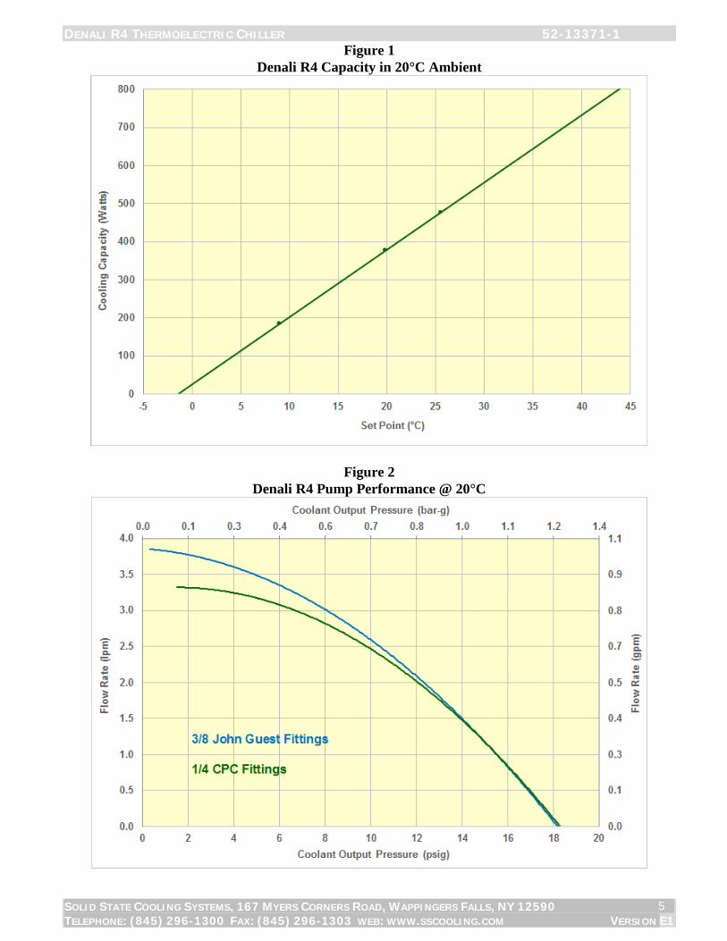
Cooling Capacity: 380 watts @ 20°C in a 20°C ambient (See figure 1 for cooling curve)
Heating Capacity: >500 watts @ 20°C in a 20°C ambient
Noise (at 1 meter): < 45 dBA (50% loading), < 60 dBA (max load)
Coolant Type: 27% Propylene Glycol and Water recommended preventing bacterial growth and minimizing noise and extending pump life. (Note: propylene glycol is non-toxic). SSCS Recommends Koolance LIQ-702CL-B coolant.
Ethylene Glycol and Water mixtures are also acceptable. Note: Methanol, Ethanol, or Isopropyl Alcohol may not be used as coolants, either by themselves or in water mixtures; use of these coolants voids the chiller warranty.
Process Fluid Fittings: 3/8” Female NPT standard, 3/8” adaptor kits available for John Guest, Swagelok, CPC, 3/8” Hose Barb or 1/4” Hose Barb
Coolant Pump: 1 to 3.8 lpm Centrifugal pump (See Figure 2 for pump curve)
Coolant Outlet Pressure: Nominal 10 psig at 2.5 lpm, Maximum 20 psig
Tank Volume: 1 liter
Wetted Materials: Copper, polymers and stainless steel
Cooling Fan: Variable Speed Fan for quiet operation
Size (W x D x H): 19” x 21” x 7” (48.3 x 53.3 x 17.8 cm)
Weight: 41 lbs (18.6 kg)
Power Input: Universal 100-240 VAC, 50/60 Hz, 9/4 amps max
Communications: Keypad or USB interface
Alarms: Temperature, fluid level, system or component failure
Safety Certifications: (with power supply) CE/ UL (TUV) EN 61010-1: 3rd Edition UL 61010-1: 3rd Edition CAN/CSA 61010-1: 3rd Edition
RoHS RoHS Compliant
DENALI R4 THERMOELECTRIC CHILLER 52-13371-1
SOLID STATE COOLING SYSTEMS, 167 MYERS CORNERS ROAD, WAPPINGERS FALLS, NY 12590 TELEPHONE: (845) 296-1300 FAX: (845) 296-1303 WEB: WWW.SSCOOLING.COM VERSION E1
5
Figure 1 Denali R4 Capacity in 20°C Ambient
Figure 2 Denali R4 Pump Performance @ 20°C

DENALI R4 THERMOELECTRIC CHILLER 52-13371-1
SOLID STATE COOLING SYSTEMS, 167 MYERS CORNERS ROAD, WAPPINGERS FALLS, NY 12590 TELEPHONE: (845) 296-1300 FAX: (845) 296-1303 WEB: WWW.SSCOOLING.COM VERSION E1
6
SECTION 3 HOOK UP _______________________________________________________ Figure 3A: Front View
Drain
Figure 3B: Rear View Coolant Supply (Process Out) Communications Port (USB)
Coolant Return (Process In) AC Power Inlet (IEC320 - C14) with 5X20 10A fast acting fuse
ON/OFF Switch
Key Pad Display Screen Tank Vent Spout Plug, Lift Tab to Open

DENALI R4 THERMOELECTRIC CHILLER 52-13371-1
SOLID STATE COOLING SYSTEMS, 167 MYERS CORNERS ROAD, WAPPINGERS FALLS, NY 12590 TELEPHONE: (845) 296-1300 FAX: (845) 296-1303 WEB: WWW.SSCOOLING.COM VERSION E1
7
3.1 MECHANICAL INSTALLATION The Denali R4 is designed for installation into EIA-310-C standard 19 inch electronics rack. The chiller must rest on two rails, at least 16 inches in length, installed into the electronics rack. Rails may be purchased from SSCS, PN 30-22737-1, or from Allied Electronics PN 806-6880. Place the chiller on top of these rails and slide into place. Once in place, use four #10 mounting screws to fasten the chiller to the electronics rack. Easy access must be given to the power inlet (located above the plumbing connections on the back panel of the unit) to allow for service.
Air Considerations: The air inlet and outlet are located on the front and back sides respectively. Restricting airflow into or out of the unit will impair performance. At least 6 inches of clearance is required in front and in back to ensure adequate airflow.
3.2 ELECTRICAL CONNECTIONS (SEE FIGURE 3B) Power: The Denali R4 AC power inlet is an IEC320-C14 socket. Plug the line cord provided into this socket and then into the appropriate 100 - 240 VAC 50/60 Hz wall outlet. To ensure safe operation of the unit, it is important to ensure that the outlet is properly grounded. A wide variety of power cords are available to support universal power operation:
Country / Region Part Number USA/Canada 22-22333-1 Europe 22-22333-2 Japan 22-22333-3 UK 22-22333-4 Israel 22-22800-1 Australia 22-23213-1 Korean 22-23526-1 China (3 prong) 22-23661-1 NEMA 6-15 208 US Straight 16-23918-1 NEMA L6-15 208 US Twist 16-23918-2
Fuse: 10 amp (5mm x 20mm) GDB quick acting glass, meets IEC 127-2 Replacement Fuse: SSCS#20-22332-10, Allied Electronics #740-9575 Remote Communication: Remote control of the unit may be achieved by connecting to the USB type B port on the rear panel. For more information, refer to section 7.2.
WARNING
Electrical Shock Hazard: Never Plug in a Line Cord with
Wet Hands
DENALI R4 THERMOELECTRIC CHILLER 52-13371-1
SOLID STATE COOLING SYSTEMS, 167 MYERS CORNERS ROAD, WAPPINGERS FALLS, NY 12590 TELEPHONE: (845) 296-1300 FAX: (845) 296-1303 WEB: WWW.SSCOOLING.COM VERSION E1
8
3.3 PLUMBING CONNECTIONS (SEE FIGURE 3B)
The process fluid outlet (coolant supply) and inlet (coolant return) connections are brass 3/8” NPT fittings, other options are listed below:
Fitting Type Part Number 1/4” John Guest 14-13232-1 3/8” John Guest 14-13232-2 1/4” Hose Barb 14-13232-3 3/8” Hose barb 14-13232-4 1/4” Swagelok 14-13232-5 3/8” Swagelok 14-13232-6 1/4” Colder Valved Quick Disconnect 14-13232-7
3.4 COOLANT FILL Procedure: 1) Open Tank Vent (push in small ring around the plastic plug and pull the plug out of the fitting). 2) Open Fill Spout (lift tab on plug and pull out plug). 3) Carefully pour in coolant until the level reaches “Max”. 4) Turn on the chiller, adding coolant as required maintaining the tank level just below maximum. 5) Insert plug into spout, press down tab once plug is in place. 6) Plug vent prior to operating.
Recommended Coolants:
SSCS recommends using Koolance, a pre-mixed 27% propylene glycol/water based coolant containing an algaecide and corrosion inhibitors. Though it comes in several colors, SSCS recommends the colorless or blue versions in 700 ml bottles, part number: LIQ-702CL-B (clear) or LIQ-702B-B (blue), as the dyes in the other colored versions can form small particulates when not well mixed.
Contact Koolance for details:
Koolance USA 2840 West Valley Highway North Auburn, WA 98001 (253) 893-7551
WARNING
Read the Coolant MSDS Prior to filling the chiller
CAUTION
Use only recommended
coolants

DENALI R4 THERMOELECTRIC CHILLER 52-13371-1
SOLID STATE COOLING SYSTEMS, 167 MYERS CORNERS ROAD, WAPPINGERS FALLS, NY 12590 TELEPHONE: (845) 296-1300 FAX: (845) 296-1303 WEB: WWW.SSCOOLING.COM VERSION E1
9
SECTION 4 START UP ______________________________________________________ Note: In order to avoid injury or damage, operators must only use this product in the
manner specified below.
Start-up the chiller using the following steps: 1) Connect coolant tubing to fluid connections located on the rear
panel, labeled Process Out (supply) and Process In (return). 2) Connect USB signal cable (optional). 3) Remove the reservoir cap on top and add more coolant as
necessary to bring the coolant level to maximum (per section 3.5). Replace cap.
4) Plug line cord into 100 - 240 VAC, 50/60 Hz. 5) Turn on switch located on the front. The front display should
read the current coolant temperature. If the front display reads “TANK LEVEL LOW”, add more coolant to the reservoir until the display changes to read the coolant temperature.
Important Notes:
1) If the tank level low alarm persists, or if another alarm is displayed, consult section 6.0 of this manual.
2) When starting up the Denali R4 for the first time, the pump may have difficulty priming. If this occurs, the pump will make a loud, high-pitched sound. If this sound is heard, immediately turn off the system and restart the system. It may take several on/off cycles to properly prime the pump.
SECTION 5 OPERATION _____________________________________________________
The Denali R4 is operated via the control panel located on the front panel. The control panel has an 8-character by 2 line LCD display and four input keys: UP, DOWN, ENTER, and START/STOP. These keys work as follows:
Key Action UP Pressing the UP key raises the parameter value displayed. DOWN Pressing the DOWN key lowers the parameter value displayed ENTER Pressing the ENTER key momentarily enters the parameter changed. ENTER Pressing and holding the ENTER key for 3 seconds causes the chiller to ask for a
password to enter the parameter menu.
WARNING
Electrical Shock Hazard: Never Plug in a Line Cord with
Wet Hands

DENALI R4 THERMOELECTRIC CHILLER 52-13371-1
SOLID STATE COOLING SYSTEMS, 167 MYERS CORNERS ROAD, WAPPINGERS FALLS, NY 12590 TELEPHONE: (845) 296-1300 FAX: (845) 296-1303 WEB: WWW.SSCOOLING.COM VERSION E1
10
5.1 SIMPLE OPERATION
The Denali R4 comes with preset operating parameters that will work well for most applications. If temperature control at one temperature is desired, follow the steps below. 1) Turn on chiller and wait for display to read TEMP. 2) Press the UP or DOWN keys to change SETTEMP to the desired set
point. 3) Press the ENTER key. 4) Caution: Do not externally shut off the flow of coolant for more than
a ten second period; pump damage will result if run deadheaded for extended periods of time.
The chiller will now control to the set point temperature. To change the set point temperatures just press the UP or DOWN keys again to change SETTEMP 1 to the new set point, followed by the ENTER key.
5.2 ADVANCED OPERATION The chiller has two menus: the Status Menu and the Parameter Input Menu. The Status Menu shows the chiller operating status and current temperature of fluid leaving the chiller. The Status Menu also allows input of new coolant temperature set-points. The Parameter Input Menu allows input of the Alarm Range, the temperature Offset, and the Back Light on/off command.

DENALI R4 THERMOELECTRIC CHILLER 52-13371-1
SOLID STATE COOLING SYSTEMS, 167 MYERS CORNERS ROAD, WAPPINGERS FALLS, NY 12590 TELEPHONE: (845) 296-1300 FAX: (845) 296-1303 WEB: WWW.SSCOOLING.COM VERSION E1
11
Figure 4 Denali R4 Display – Status menu Operating Modes: * = Standby mode, no temperature control H = Heating mode with temperature control within alarm range C = Cooling mode with temperature control within alarm range > = Cooling mode, coolant temperature is above the alarm range < = Heating mode, coolant temperature is below the alarm range The coolant outlet temperature is shown below TEMP in °C.
Pressing the UP or DOWN keys will change the set point temperature upon pressing the ENTER key. The chiller has a parameter menu screen containing several user adjustable parameters. To access this menu press and hold the ENTER button for 3 seconds, and then enter password 0000 using the UP, DOWN and ENTER keys. This menu allows access to the following parameters:
MENU STRUCTURE: NOMENCLATURE: UP or Increase Value Down or Decrease Value ↵ Press Enter Momentarily Press & Hold Enter Key 3 Sec
SIMPLE OPERATION ADVANCED OPERATION (STATUS MENU) press and hold enter key (PARAMETER INPUT MENU)
TEMP: XX.X°C (current temp) PASSWORD XXXX PRESS OR (change set point) ↵ SETTEMP1 XX.X°C ALRM +/- XX°C ↵ ↵ TEMP: XX.X°C (current temp) OFFSET X.X°C ↵ TEMPUNIT °C/°F ↵ BK LIGHT ON/OFF ↵ (return to top of menu) Press ENTER key once to scroll between menu items (↵). Press and hold ENTER key for 3 seconds to enter the parameter input menu ( ). Note: If the user enters the temperature input or the parameter input menu and does not press a key for 10 seconds the display will revert back to the Status menu.
C TEMP 20.0°C
Operating Mode Symbol

DENALI R4 THERMOELECTRIC CHILLER 52-13371-1
SOLID STATE COOLING SYSTEMS, 167 MYERS CORNERS ROAD, WAPPINGERS FALLS, NY 12590 TELEPHONE: (845) 296-1300 FAX: (845) 296-1303 WEB: WWW.SSCOOLING.COM VERSION E1
12
Status Menu: The status menu displays the chiller operating status and coolant temperature. The chiller operating mode is shown in the display’s first character: (See Figure 4)
ALRM +/-: Alarm width, the acceptable coolant operating temperature range around set-point before an alarm is communicated via USB. For example, if set to 5°C with a 20°C set-point, an alarm will trigger if the coolant temperature rises above 25°C or falls below 15°C.
OFFSET: This parameter raises or lowers the chiller temperature reading to match a user’s external temperature sensor. Enter the difference between the external sensor and the display. For example, if the user has a temperature sensor reading of 22 °C when the chiller display shows 20°C, entering 22°C – 20°C = 2°C will cause the chiller to shift its temperature calibration scale up 2°C to match the external sensor.
TEMPUNIT: Sets temperature units in degrees Celsius or Fahrenheit.
BKLIGHT: Setting this parameter to ON turns on the display back-light; setting this parameter to OFF turns off the display back-light.
5.3 ALARMS Alarms are displayed on the front screen, and communicated through USB interface.
A list of system failure modes can be found in Section 6. In the event of a system failure, the alarm type will be shown on the front display.
5.4 DRAIN PROCEDURE 1. Connect one end of the drain hose with the Colder Products
PLCD2204 coupling insert provided with the Denali R4 into the front drain fitting (see figure 3A) and place the other end into a container with at least a 2 liter capacity.
2. Remove the tank vent plug (push in small ring around the aluminum plug and pull the plug out of the fitting).
3. Allow the tank to drain. 4. Connect a short loop to between the chiller’s coolant supply and
return lines. (If the normal coolant lines are short, <6ft (2m) this step may be skipped.)
5. Turn on the Denali R4 for 15-20 seconds, and then turn off. 6. A small amount of coolant will remain in the bottom of the tank.
Removing this remainder (not necessary to ship the unit) requires lifting the rear of the chassis.
7. Remove the drain hose. 8. Insert the tank vent plug removed in step 2.

DENALI R4 THERMOELECTRIC CHILLER 52-13371-1
SOLID STATE COOLING SYSTEMS, 167 MYERS CORNERS ROAD, WAPPINGERS FALLS, NY 12590 TELEPHONE: (845) 296-1300 FAX: (845) 296-1303 WEB: WWW.SSCOOLING.COM VERSION E1
13
SECTION 6 SYSTEM ALARMS/TROUBLESHOOTING ________________________________
The Denali R4 has four system alarms that when triggered will show on the display. When an alarm is displayed the system will not attempt to heat or cool the coolant.
Alarms: Tank Level Low: Liquid reservoir level is too low. This is a warning and the unit will continue to control temperature under this condition. Unless filling for the first time, check all outside plumbing lines for leaks. Once all leaks are sealed, remove the cap and add more coolant until the alarm disappears.
RTD Open: The temperature sensor has failed. Temperature control will stop. Turn off the chiller and disconnect the AC power cord. Contact SSCS for an RMA number to return the unit for RTD replacement.
Fan Fail: The Denali R4 checks fan operation at startup. Fan fail indicates the fan has stopped working. The unit will not start temperature control. Contact SSCS for an RMA number to return the unit for fan replacement.
Pump Fail: The liquid heat exchanger plate temperature is either too hot or too cold, indicating a pump failure or a blockage in the external plumbing lines. Temperature control will stop. Turn off the chiller and disconnect the AC power cord. Verify that no kinks or blockages exist in external plumbing line. If no coolant flow blockages exist, contact SSCS for a RMA number to return the unit for pump replacement.
Other issues: Temperature Control Poor: If no other alarms are present, poor temperature control can indicate blocked airflow or that the TE cooling/heating engine is not receiving power or has failed. If the chiller cools but cannot reach the set point, and the displayed temperature is higher than the set point, the heat load may be too great for the chiller, Contact SSCS for technical support. Important: The tank level low alarm will automatically reset when the tank is filled. The RTD, Fan and Pump failure alarms will not reset until the system power is turned off.
Do not remove cover or attempt to repair unit,
as electrical shock hazards exist inside.
WARNING

DENALI R4 THERMOELECTRIC CHILLER 52-13371-1
SOLID STATE COOLING SYSTEMS, 167 MYERS CORNERS ROAD, WAPPINGERS FALLS, NY 12590 TELEPHONE: (845) 296-1300 FAX: (845) 296-1303 WEB: WWW.SSCOOLING.COM VERSION E1
14
SECTION 7 USB COMMUNICATIONS ___________________________________________
The Denali R4 comes with a USB serial communications capability that can receive a remote set point, return the current temperature, and signal an alarm has occurred. Communicating with the chiller via USB with requires installing a Silicon Labs CP210x driver on the host computer. This driver, along with installation instructions, can be found on the CD containing this manual. Note: The chiller’s front keypad will lock out upon initiation of USB communications. USB communications software is available, contact SSCS for details.
Connector Type: Type-B
Speed: 9600 baud
Number of Start bits: 1
Number of Stop bits: 1
Parity: None
Host/Device: Denali R4 is the device, PC is the host
Interrupts Reported: None, must be polled for status
Data Format: ASCII
Insert a carriage return (0x0Dh) at the end of each command string. Table 2 USB Commands
PARAMETER GET Data Command
Response PUT Data Command
Response
show all parameters ALL? (all data) Show chiller identification information
IDN? Solid State Cooling, Product Name, Model#, Software Number & Revision, Serial Number
Put chiller in LOCAL mode LOCAL Chiller: run, stop RUN? RUNNING or STOPPED RUN, STOP RTD temp TEMP? (-)XX.X Set-point Temperature SETTEMP? (-)XX.X SETTEMP (-)XX.X Temperature Alarm width (+/-) WIDTH? XX.X WIDTH XX.X RTD offset OFFSET? (-)XX.X OFFSET (-)XX.X Display backlight on/off - BLON, BLOFF Pump temperature PUMPTEMP? (-)XX.X Actual TE PWM % PWM? (-)XX.X Status word 1 (5 ASCII bytes) STAT1A? 0 - 65535 Faults word 1 (5 ASCII bytes) FLTS1A? 0 - 65535
NOTES: 1. All commands are case insensitive 2. The chiller will automatically begin operating in REMOTE mode upon initiation of USB
communications. This will lock-out the keypad. 3. The chiller performs actions upon receiving LOCAL, RUN/STOP and BLON/BLOFF commands,
but does not send back a USB response.

DENALI R4 THERMOELECTRIC CHILLER 52-13371-1
SOLID STATE COOLING SYSTEMS, 167 MYERS CORNERS ROAD, WAPPINGERS FALLS, NY 12590 TELEPHONE: (845) 296-1300 FAX: (845) 296-1303 WEB: WWW.SSCOOLING.COM VERSION E1
15
STAT1A Bit Field Definition: |__ __ __ __ | __ __ __ __ | __ __ __ __ | __ __ __ __ | | | | | | | | | | | | | | | | |___Chiller Running? 1 = RUNNING, 0 = STOPPED | | | | | | | | | | | | | | |_____Remote or Local 1 = REMOTE, 0 = LOCAL | | | | | | | | | | | | | |________Chiller Ready? 1 = READY, 0 = NOTREADY | | | | | | | | | | | | |__________Temp low alarm 1 = Temp < SP - WIDTH | | | | | | | | | | | |______________Temp high alarm 1 = Temp > SP + WIDTH | | | | | | | | | | |_____________Chiller Heating or Cooling 1 = HEATING, 0 = COOLING | | | | | | | | | |__________________System Warning 1 = WARNING, 0 = NONE | | | | | | | | |_____________________System Alarm 1 = ALARM, 0 = NONE |_______ rsvd ____| |__________________________ rsvd The Warning bit is triggered by tank level low and a temperature outside of the +/- alarm width. The Alarm bit is triggered by an RTD fault, a pump fault, or a fan fault. FLTS1A Bit Field Definition (Fault=”1”) |__ __ __ __ | __ __ __ __ | __ __ __ __ | __ __ __ __ | | | | | | | | | | | | | | | | |___ RTD | | | | | | | | | | | | | | |_____ Tank Level Low | | | | | | | | | | | | | |________ Pump Fail | | | | | | | | | | | | |__________ Fan Fail | | | | | | | | | | | |______________ rsvd | | | | | | | | | | |_________________ rsvd | | | | | | | | | |___________________ rsvd | | | | | | | | |______________________ rsvd | | | | | | | |__________________________ rsvd | | | | | | |____________________________ rsvd | | | | | |_______________________________ rsvd | | | | |_________________________________ rsvd |_ rsvd_|
SECTION 8 CLEANING YOUR CHILLER
The exterior surfaces of the Denali R4 may be cleaned with a non-shedding wipe dipped in isopropyl alcohol.
SECTION 9 TECHNICAL SUPPORT _____________________________________________
Delighting our customers is our highest priority. Please contact us immediately for technical assistance whenever you have questions or concerns. Hours: 8 a.m. to 5 p.m. Eastern Time, Monday - Friday Telephone: (845) 296-1300 Fax: (845) 296-1303 E-mail: [email protected]

DENALI R4 THERMOELECTRIC CHILLER 52-13371-1
SOLID STATE COOLING SYSTEMS, 167 MYERS CORNERS ROAD, WAPPINGERS FALLS, NY 12590 TELEPHONE: (845) 296-1300 FAX: (845) 296-1303 WEB: WWW.SSCOOLING.COM VERSION E1
16
SECTION 10 MSDS FOR COOLANTS

DENALI R4 THERMOELECTRIC CHILLER 52-13371-1
SOLID STATE COOLING SYSTEMS, 167 MYERS CORNERS ROAD, WAPPINGERS FALLS, NY 12590 TELEPHONE: (845) 296-1300 FAX: (845) 296-1303 WEB: WWW.SSCOOLING.COM VERSION E1
17

DENALI R4 THERMOELECTRIC CHILLER 52-13371-1
SOLID STATE COOLING SYSTEMS, 167 MYERS CORNERS ROAD, WAPPINGERS FALLS, NY 12590 TELEPHONE: (845) 296-1300 FAX: (845) 296-1303 WEB: WWW.SSCOOLING.COM VERSION E1
18

DENALI R4 THERMOELECTRIC CHILLER 52-13371-1
SOLID STATE COOLING SYSTEMS, 167 MYERS CORNERS ROAD, WAPPINGERS FALLS, NY 12590 TELEPHONE: (845) 296-1300 FAX: (845) 296-1303 WEB: WWW.SSCOOLING.COM VERSION E1
19

DENALI R4 THERMOELECTRIC CHILLER 52-13371-1
SOLID STATE COOLING SYSTEMS, 167 MYERS CORNERS ROAD, WAPPINGERS FALLS, NY 12590 TELEPHONE: (845) 296-1300 FAX: (845) 296-1303 WEB: WWW.SSCOOLING.COM VERSION E1
20

DENALI R4 THERMOELECTRIC CHILLER 52-13371-1
SOLID STATE COOLING SYSTEMS, 167 MYERS CORNERS ROAD, WAPPINGERS FALLS, NY 12590 TELEPHONE: (845) 296-1300 FAX: (845) 296-1303 WEB: WWW.SSCOOLING.COM VERSION E1
21
MSDS for Ethylene Glycol ETHYLENE GLYCOL
MSDS Number: E5125 --- Effective Date: 02/25/99
1. PRODUCT IDENTIFICATION
Synonyms: 1,2-Ethanediol; glycol; 1,2-Dihydroxyethane; Ethylene Alcohol; Ethylene Dihydrate CAS No.: 107-21-1 Molecular Weight: 62.07 Chemical Formula: CH2OHCH2OH Product Codes: J.T. Baker: 5387, 5845, 9140, 9298, 9300, 9346, 9349, 9356, L715 Mallinckrodt: 5001, 5037
2. COMPOSITION/INFORMATION ON INGREDIENTS Ingredient CAS No Percent Hazardous --------------------------------------- ------------ ------- --------- Ethylene Glycol 107-21-1 99 - 100% Yes
3. HAZARDS IDENTIFICATION
Emergency Overview ------------------------------------------------------------------------! HARMFUL OR FATAL IF SWALLOWED. HARMFUL IF INHALED OR ABSORBED THROUGH SKIN. MAY CAUSE ALLERGIC SKIN REACTION. MAY CAUSE IRRITATION TO SKIN, EYES, AND RESPIRATORY TRACT. AFFECTS CENTRAL NERVOUS SYSTEM. J.T. Baker SAF-T-DATA(tm) Ratings (Provided here for your convenience) ------------------------------------------------------------------------- Health Rating: 2 - Moderate Flammability Rating: 1 - Slight Reactivity Rating: 1 - Slight Contact Rating: 2 - Moderate Lab Protective Equip: GOGGLES; LAB COAT; VENT HOOD; PROPER GLOVES Storage Color Code: Orange (General Storage)
POTENTIAL HEALTH EFFECTS ---------------------------------------
Inhalation: Vapor inhalation is generally not a problem unless heated or misted. Exposure to vapors over an extended time period has caused throat irritation and headache. May cause nausea, vomiting, dizziness and drowsiness. Pulmonary edema and central nervous system depression may also develop. When heated or misted, has produced rapid, involuntary eye movement and coma. Ingestion: Initial symptoms in massive dosage parallel alcohol intoxication, progressing to CNS depression, vomiting, headache, rapid respiratory and heart rate, lowered blood pressure, stupor, collapse, and unconsciousness with convulsions. Death from respiratory arrest or cardiovascular collapse may follow.

DENALI R4 THERMOELECTRIC CHILLER 52-13371-1
SOLID STATE COOLING SYSTEMS, 167 MYERS CORNERS ROAD, WAPPINGERS FALLS, NY 12590 TELEPHONE: (845) 296-1300 FAX: (845) 296-1303 WEB: WWW.SSCOOLING.COM VERSION E1
22
Lethal dose in humans: 100 ml (3-4 ounces). Skin Contact: Minor skin irritation and penetration may occur. Eye Contact: Splashes may cause irritation, pain, and eye damage. Chronic Exposure: Repeated small exposures by any route can cause severe kidney problems. Brain damage may also occur. Skin allergy can develop. May damage the developing fetus. Aggravation of Pre-existing Conditions: Persons with pre-existing skin disorders, eye problems, or impaired liver, kidney, or respiratory function may be more susceptible to the effects of this substance.
4. FIRST AID MEASURES Inhalation: Remove to fresh air. If not breathing, give artificial respiration. If breathing is difficult, give oxygen. Call a physician. Ingestion: Induce vomiting immediately as directed by medical personnel. Never give anything by mouth to an unconscious person. Get medical attention. Skin Contact: Remove any contaminated clothing. Wash skin with soap and water for at least 15 minutes. Get medical attention if irritation develops or persists. Eye Contact: Immediately flush eyes with plenty of water for at least 15 minutes, lifting lower and upper eyelids occasionally. Get medical attention immediately. Note to Physician: Give sodium bicarbonate intravenously to treat acidosis. Urinalysis may show low specific gravity, proteinuria, pyuria, cylindruria, hematuria, calcium oxide, and hippuric acid crystals. Ethanol can be used in antidotal treatment but monitor blood glucose when administering ethanol because it can cause hypoglycemia. Consider infusion of a diuretic such as mannitol to help prevent or control brain edema and hemodialysis to remove ethylene glycol from circulation.
5. FIRE FIGHTING MEASURES
Fire: Flash point: 111C (232F) CC Autoignition temperature: 398C (748F) Flammable limits in air % by volume: lel: 3.2; uel: 15.3 Slight to moderate fire hazard when exposed to heat or flame. Explosion: Above flash point, vapor-air mixtures are explosive within flammable limits noted above. Containers may explode when involved in a fire. Fire Extinguishing Media: Dry chemical, foam or carbon dioxide. Water or foam may cause frothing. Water spray may be used to extinguish surrounding fire and cool exposed containers. Water spray will also reduce fume and irritant gases. Special Information: In the event of a fire, wear full protective clothing and NIOSH-approved self-contained breathing

DENALI R4 THERMOELECTRIC CHILLER 52-13371-1
SOLID STATE COOLING SYSTEMS, 167 MYERS CORNERS ROAD, WAPPINGERS FALLS, NY 12590 TELEPHONE: (845) 296-1300 FAX: (845) 296-1303 WEB: WWW.SSCOOLING.COM VERSION E1
23
apparatus with full-face piece operated in the pressure demand or other positive pressure mode. Toxic gases and vapors may be released if involved in a fire.
6. ACCIDENTAL RELEASE MEASURES
Ventilate area of leak or spill. Remove all sources of ignition. Wear appropriate personal protective equipment as specified in Section 8. Isolate hazard area. Keep unnecessary and unprotected personnel from entering. Contain and recover liquid when possible. Use non-sparking tools and equipment. Collect liquid in an appropriate container or absorb with an inert material (e. g., vermiculite, dry sand, earth), and place in a chemical waste container. Do not use combustible materials, such as sawdust. Do not flush to sewer! US Regulations (CERCLA) require reporting spills and releases to soil, water and air in excess of reportable quantities. The toll free number for the US Coast Guard National Response Center is (800) 424-8802.
7. HANDLING AND STORAGE
Keep in a tightly closed container, stored in a cool, dry, ventilated area. Protect against physical damage. Separate from acids and oxidizing materials. Containers of this material may be hazardous when empty since they retain product residues (vapors, liquid); observe all warnings and precautions listed for the product.
8. EXPOSURE CONTROLS/PERSONAL PROTECTION
Airborne Exposure Limits: -OSHA Permissible Exposure Limit (PEL): 50 ppm Ceiling -ACGIH Threshold Limit Value (TLV): 50 ppm Ceiling (vapor) Ventilation System: A system of local and/or general exhaust is recommended to keep employee exposures below the Airborne Exposure Limits. Local exhaust ventilation is generally preferred because it can control the emissions of the contaminant at its source, preventing dispersion of it into the general work area. Please refer to the ACGIH document, Industrial Ventilation, A Manual of Recommended Practices, most recent edition, for details. Personal Respirators (NIOSH Approved): If the exposure limit is exceeded, a half-face respirator with an organic vapor cartridge and particulate filter (NIOSH type P95 or R95 filter) may be worn for up to ten times the exposure limit or the maximum use concentration specified by the appropriate regulatory agency or respirator supplier, whichever is lowest. A full-face piece respirator with an organic vapor cartridge and particulate filter (NIOSH P100 or R100 filter) may be worn up to 50 times the exposure limit, or the maximum use concentration specified by the appropriate regulatory agency or respirator supplier, whichever is lowest. Please note that N series filters are not recommended for this material. For emergencies or instances where the exposure levels are not known, use a full-face piece positive-pressure, air-supplied respirator. WARNING: Air-purifying respirators do not protect workers in oxygen-deficient atmospheres. Skin Protection: Wear protective gloves and clean body-covering clothing. Eye Protection: Use chemical safety goggles. Maintain eye wash fountain and quick-drench facilities in work area.

DENALI R4 THERMOELECTRIC CHILLER 52-13371-1
SOLID STATE COOLING SYSTEMS, 167 MYERS CORNERS ROAD, WAPPINGERS FALLS, NY 12590 TELEPHONE: (845) 296-1300 FAX: (845) 296-1303 WEB: WWW.SSCOOLING.COM VERSION E1
24
9. PHYSICAL AND CHEMICAL PROPERTIES
Appearance: Clear oily liquid. Odor: Odorless. Solubility: Miscible in water. Specific Gravity: 1.1 @20C/4C pH: No information found. % Volatiles by volume @ 21C (70F): 100 Boiling Point: 197.6C (388F) Melting Point: -13C (9F) Vapor Density (Air=1): 2.14 Vapor Pressure (mm Hg): 0.06 @ 20C (68F) Evaporation Rate (BuAc=1): No information found.
10. STABILITY AND REACTIVITY
Stability: Stable under ordinary conditions of use and storage. Hazardous Decomposition Products: Carbon dioxide and carbon monoxide may form when heated to decomposition. May produce acrid smoke and irritating fumes when heated to decomposition. Hazardous Polymerization: Will not occur. Incompatibilities: Strong oxidizing agents. Reacts violently with chlorosulfonic acid, oleum, sulfuric acid, perchloric acid. Causes ignition at room temperature with chromium trioxide, potassium permanganate and sodium peroxide; causes ignition at 212F(100C) with ammonium dichromate, silver chlorate, sodium chloride and uranyl nitrate. Conditions to Avoid: Heat, flames, ignition sources, water (absorbs readily) and incompatibles.

DENALI R4 THERMOELECTRIC CHILLER 52-13371-1
SOLID STATE COOLING SYSTEMS, 167 MYERS CORNERS ROAD, WAPPINGERS FALLS, NY 12590 TELEPHONE: (845) 296-1300 FAX: (845) 296-1303 WEB: WWW.SSCOOLING.COM VERSION E1
25
11. TOXICOLOGICAL INFORMATION
Toxicological Data: Oral rat LD50: 4700 mg/kg; skin rabbit LD50: 9530 mg/kg. Irritation - skin rabbit: 555mg(open), mild; eye rabbit: 500mg/24H, mild. Investigated as a tumorigen, mutagen, reproductive effector.
Reproductive Toxicity: Has shown teratogenic effects in laboratory animals. --------\Cancer Lists\------------------------------------------------------ ---NTP Carcinogen--- Ingredient Known Anticipated IARC Category ------------------------------------ ----- ----------- ------------- Ethylene Glycol (107-21-1) No No None
12. ECOLOGICAL INFORMATION
Environmental Fate: When released into the soil, this material is expected to readily biodegrade. When released into the soil, this material is expected to leach into groundwater. When released into the soil, this material is not expected to evaporate significantly. When released into water, this material is expected to readily biodegrade. When released into the water, this material is expected to have a half-life between 1 and 10 days. This material is not expected to significantly bioaccumulate. This material has a log octanol-water partition coefficient of less than 3.0. When released into water, this material is not expected to evaporate significantly. When released into the air, this material is expected to be readily degraded by reaction with photochemically produced hydroxyl radicals. When released into the air, this material is expected to have a half-life between 1 and 10 days. Environmental Toxicity: The LC50/96-hour values for fish are over 100 mg/l.
13. DISPOSAL CONSIDERATIONS
Whatever cannot be saved for recovery or recycling should be managed in an appropriate and approved waste disposal facility. Processing, use or contamination of this product may change the waste management options. State and local disposal regulations may differ from federal disposal regulations. Dispose of container and unused contents in accordance with federal, state and local requirements.
14. TRANSPORT INFORMATION
Not regulated.
15. REGULATORY INFORMATION --------\Chemical Inventory Status - Part 1\--------------------------------- Ingredient TSCA EC Japan Australia ----------------------------------------------- ---- --- ----- --------- Ethylene Glycol (107-21-1) Yes Yes Yes Yes --------\Chemical Inventory Status - Part 2\--------------------------------- --Canada-- Ingredient Korea DSL NDSL Phil. ----------------------------------------------- ----- --- ---- ----- Ethylene Glycol (107-21-1) Yes Yes No Yes

DENALI R4 THERMOELECTRIC CHILLER 52-13371-1
SOLID STATE COOLING SYSTEMS, 167 MYERS CORNERS ROAD, WAPPINGERS FALLS, NY 12590 TELEPHONE: (845) 296-1300 FAX: (845) 296-1303 WEB: WWW.SSCOOLING.COM VERSION E1
26
--------\Federal, State & International Regulations - Part 1\---------------- -SARA 302- ------SARA 313------ Ingredient RQ TPQ List Chemical Catg. ----------------------------------------- --- ----- ---- -------------- Ethylene Glycol (107-21-1) No No Yes No --------\Federal, State & International Regulations - Part 2\---------------- -RCRA- -TSCA- Ingredient CERCLA 261.33 8(d) ----------------------------------------- ------ ------ ------ Ethylene Glycol (107-21-1) 5000 No No Chemical Weapons Convention: No TSCA 12(b): No CDTA: No SARA 311/312: Acute: Yes Chronic: Yes Fire: No Pressure: No Reactivity: No (Pure / Liquid)
Australian Hazchem Code: No information found. Poison Schedule: No information found. WHMIS: This MSDS has been prepared according to the hazard criteria of the Controlled Products Regulations (CPR) and the MSDS contains all of the information required by the CPR.
16. OTHER INFORMATION
NFPA Ratings: Health: 1 Flammability: 1 Reactivity: 0 Label Hazard Warning: WARNING! HARMFUL OR FATAL IF SWALLOWED. HARMFUL IF INHALED OR ABSORBED THROUGH SKIN. MAY CAUSE ALLERGIC SKIN REACTION. MAY CAUSE IRRITATION TO SKIN, EYES, AND RESPIRATORY TRACT. AFFECTS CENTRAL NERVOUS SYSTEM.
Label Precautions: Do not breathe vapor or mist. Use only with adequate ventilation. Keep container closed. Avoid contact with eyes, skin and clothing. Wash thoroughly after handling. Label First Aid: If inhaled, remove to fresh air. If not breathing, give artificial respiration. If breathing is difficult, give oxygen. In case of contact, immediately flush skin or eyes with plenty of water for at least 15 minutes. Call a physician if irritation develops or persists. If swallowed, give water or milk to drink and induce vomiting. Never give anything by mouth to an unconscious person. In all cases call a physician. Product Use: Laboratory Reagent. Revision Information: MSDS Section(s) changed since last revision of document includes: 8.

DENALI R4 THERMOELECTRIC CHILLER 52-13371-1
SOLID STATE COOLING SYSTEMS, 167 MYERS CORNERS ROAD, WAPPINGERS FALLS, NY 12590 TELEPHONE: (845) 296-1300 FAX: (845) 296-1303 WEB: WWW.SSCOOLING.COM VERSION E1
27
Disclaimer:
Mallinckrodt Baker, Inc. provides the information contained herein in good faith but makes no representation as to its comprehensiveness or accuracy. This document is intended only as a guide to the appropriate precautionary handling of the material by a properly trained person using this product. Individuals receiving the information must exercise their independent judgment in determining its appropriateness for a particular purpose. MALLINCKRODT BAKER, INC. MAKES NO REPRESENTATIONS OR WARRANTIES, EITHER EXPRESS OR IMPLIED, INCLUDING WITHOUT LIMITATION ANY WARRANTIES OF MERCHANTABILITY, FITNESS FOR A PARTICULAR PURPOSE WITH RESPECT TO THE INFORMATION SET FORTH HEREIN OR THE PRODUCT TO WHICH THE INFORMATION REFERS. ACCORDINGLY, MALLINCKRODT BAKER, INC. WILL NOT BE RESPONSIBLE FOR DAMAGES RESULTING FROM USE OF OR RELIANCE UPON THIS NFORMATION.

DENALI R4 THERMOELECTRIC CHILLER 52-13371-1
SOLID STATE COOLING SYSTEMS, 167 MYERS CORNERS ROAD, WAPPINGERS FALLS, NY 12590 TELEPHONE: (845) 296-1300 FAX: (845) 296-1303 WEB: WWW.SSCOOLING.COM VERSION E1
28
WARRANTY POLICY This Solid State Cooling Systems Product is covered under a one-year parts and labor warranty from the date of shipment, assuming proper use and maintenance of the unit. All warranty work shall be performed at Solid State Cooling Systems’ facility, currently located in Wappingers Falls, NY, USA and requires pre-authorization by SSCS. Malfunctioning products should be returned to Solid State Cooling Systems by the method described below. Solid State Cooling Systems will provide a Failure Analysis Report to the customer and will determine if the problem is covered under the warranty. Warranty Coverage: Products with defects in components or manufacturing which are reported to Solid State Cooling Systems before the end of the warranty period will be repaired or replaced at no cost (see below for reporting requirements). The warranty period begins on the date the product was initially shipped from Solid State Cooling Systems’ factory. Excluded from Warranty: Excluded from warranty is any damage caused to the product occurring during, but not limited to, such events as shipment, installation, storage, or usage occurring during a situation specifically cautioned against or noted in the product manual. Specific situations, which invalidate the warranty, include (but are not limited to): Removing the serial number label. Any disassembly (partial or complete) of the product. Changing any components of the product. Subjecting the product to temperatures below the freezing point of the coolant used. Subjecting any product to temperature, voltage, current, or pressure (internal or external) greater than
that specified in the product manual. Any actions prohibited in the "Caution" section of the product manual. Returned Goods Procedure and Reporting Requirements Before a failed product is returned to the factory, a Returned Materials Authorization (RMA) number must be obtained from Customer Service at (845) 296-1300. The date the RMA is requested will be the reporting date noted and relevant to the warranty. Products, which have received an RMA, must be received at SSCS’s factory, within 30 days or the reporting date will be moved ahead 30 days and a new 30-day waiting period will begin. Customers shall pay shipping cost of returning any unit to SSCS and SSCS shall pay shipping cost of returning any unit repaired under warranty to the customer. All out of warranty returned goods will require an evaluation purchase order prior to receipt at Solid State Cooling Systems. The evaluation costs will depend on product model and will be deducted from the cost of any repairs required.