Demzy's Presentation on HDD
42
A TECHNICAL PRESENTATION HORIZONTAL DIRECTIONAL DRILLING (HDD) TECHNOLOGY GEORGE UDEMEOBONG NTA 0803 512 8478 BY ON
-
Upload
demzy-george -
Category
Documents
-
view
113 -
download
3
Transcript of Demzy's Presentation on HDD

A TECHNICAL PRESENTATION
HORIZONTAL DIRECTIONAL
DRILLING (HDD) TECHNOLOGY
GEORGE UDEMEOBONG NTA
0803 512 8478
BY
ON

Objective
• To enlighten the audience on Horizontal
Directional Drilling Technology and how it
can contribute towards developing and
securing effective pipeline infrastructure in
Nigeria.

Some of the Factors affecting development and
security of Pipeline Infrastructure in Nigeria
• Technology
• Technical Expertise
• Finance
• Vandalization
• Comprehensive Pipeline Infrastructure
Database
• Government and Regulatory Authorities
• Social Awareness

Horizontal Directional Drilling Technology
Overview
• Developed in the early 70’s
• Combination of road boring and oil well
directional drilling
• Lengths up to 3900m
• Pipelines up to 56 inch. Diameter
• Installation through sand, silts, clays
and rock

Directional Drilling Applications
• Land to Land Crossing
– Rail, Road and River Crossings
– Contaminated and environmentally significant areas
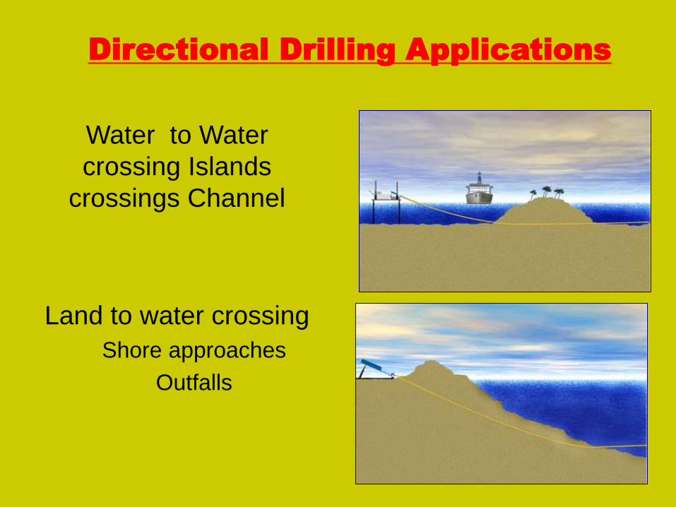
Directional Drilling Applications
Water to Water
crossing Islands
crossings Channel
Land to water crossing
Shore approaches
Outfalls
PROCEDURE FOR HDD
• INITIAL PLANNING / FEASIBILITY
• GEOTECHNICAL REVIEW
• ENGINEERING DESIGN
• INSTALLATION PROCEDURE
• PULL BACK
• DEMOBILISATION

INITIAL PLANNING/ FEASIBILITY
• Site Investigation
• Preliminary Design
• Construction Costs
• Time scale: - engineering &
preparations 3 months, drill hole 2
weeks, pull back 1 day.

Directional Drilling Installation Procedure
• Mobilization and Site Preparation
• Pre-HDD Activities Installation Procedure
• Rig-up • Temporary Casing Installation (If required)
• Pilot Hole
• Hole Opening Pass
• Pullback
• De-Mobilization

Site Preparation
• Two sites normally required
• Rig site 50m x 50m
• Pipe side and stringing site
• Staged on land and offshore
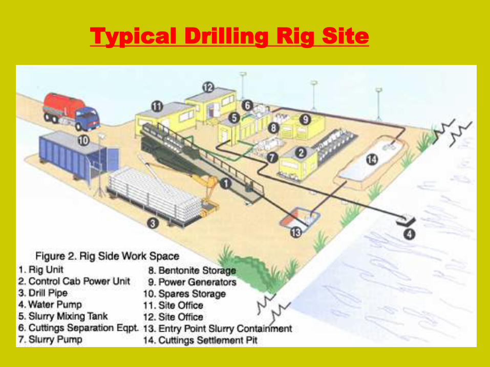
Typical Drilling Rig Site

Pilot Hole Assembly
• Jetting or rock bit
• Non-magnetic collars
• Survey tool
• Non-magnetic collars

DRILL BIT TYPE
Mill-tooth Cutter TCI - Cutter
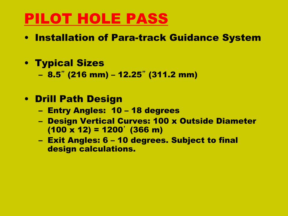
PILOT HOLE PASS
• Installation of Para-track Guidance System
• Typical Sizes
– 8.5” (216 mm) – 12.25” (311.2 mm)
• Drill Path Design
– Entry Angles: 10 – 18 degrees
– Design Vertical Curves: 100 x Outside Diameter
(100 x 12) = 1200’ (366 m)
– Exit Angles: 6 – 10 degrees. Subject to final
design calculations.
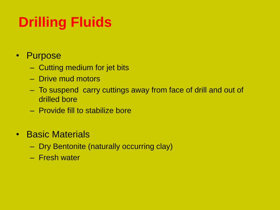
Drilling Fluids
• Purpose
– Cutting medium for jet bits
– Drive mud motors
– To suspend carry cuttings away from face of drill and out of
drilled bore
– Provide fill to stabilize bore
• Basic Materials
– Dry Bentonite (naturally occurring clay)
– Fresh water

REAMING-HOLE EXPANSION
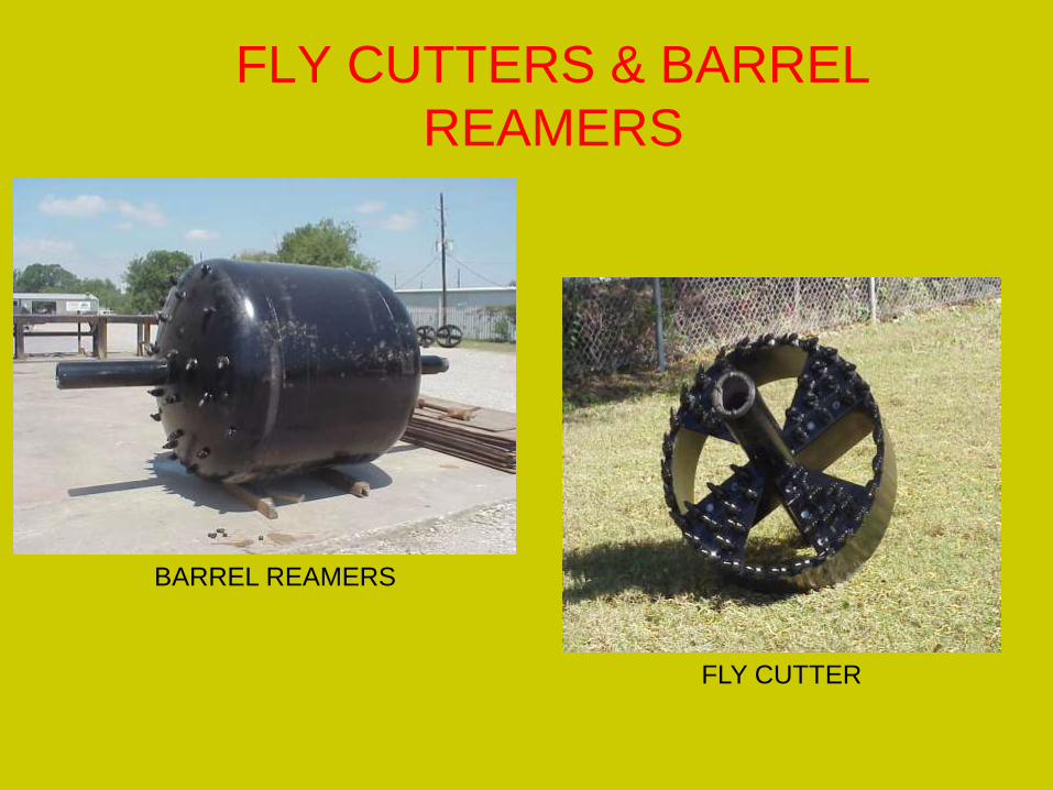
FLY CUTTERS & BARREL
REAMERS
BARREL REAMERS
FLY CUTTER

CONVENTIONAL HOLE OPENERS – MILL
TOOTH CUTTERS
PULLBACK
• Swab Pass(es)
• Connection to Carrier Pipe
• Rate of Pull
• Buoyancy Control

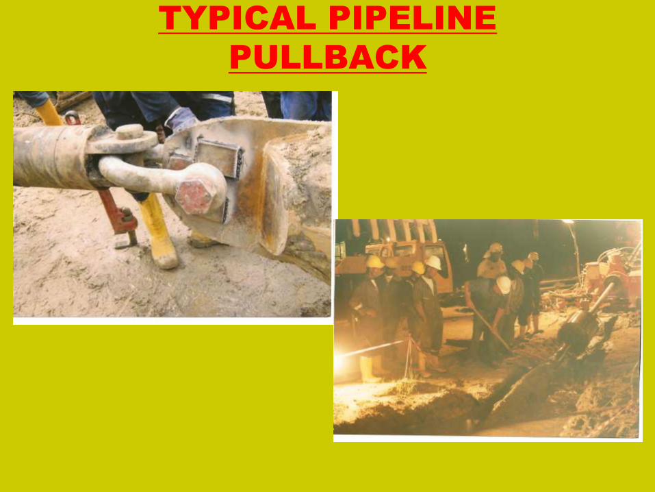
TYPICAL PIPELINE
PULLBACK

ENTRY POINT PULLBACK

Project Principles
• To assess the feasibility of a HDD project
the following basic information is required.
Environmental Considerations
Logistics
Topography
Geology

Project Principles
• Environmental Disturbance to the local
environment from Drilling
Operations.
Drilling Fluid discharge
risks, control and mitigation.
• Logistics Transport of Equipment.
Support for Drilling
Operations.
Movement of Tools.
Disposal of Cuttings and
Drilling Fluids.
Movement of Personnel

Project Principles
• Topography – Location Plan
– Area Plan
– Longitudinal Section
including levels
– Depth of Steams and
Rivers
• Geology – Evaluation of Existing
Documentation
– Historical Research
– Boreholes
– Penetration Tests
– Geophysical Tests
– Laboratory Tests
– Geotechnical Reports

GEOTECHNICAL REVIEW
• Number / Depth of Borings
• Sieve Analysis Tests
• Unconfined Compressive Strength
Tests
• Rock Quality Designation (RQD)

ENGINEERING DESIGN
• Detailed Crossing Profile Design
• Operating Stress Calculations
• Installation Stress Calculations
• Free Stress Minimum Bending Radius
• Estimated Fluid Quantity Calculations
• Pipeline Buoyancy Analysis

Equipments • Drilling Rig American Augers DD625
American Augers DD440T
Astec DD3238
MPR 6000 MUD SYSTEM
TULSA IRON 1000 MUD
SYSTEM

HDD Landfalls - General Details
• Rig located onshore, (can be placed on marine spread offshore).
• Drill to exit point from beach entry subject to pipe size and soil conditions.
• Engineer coating on pipe-string to give temporary stability during the laying of the string and to have a low friction value when being pulled through the hole.
• Pipe-string is preferably pulled directly into the hole either from a laybarge or from a pre-laid position on the seabed.
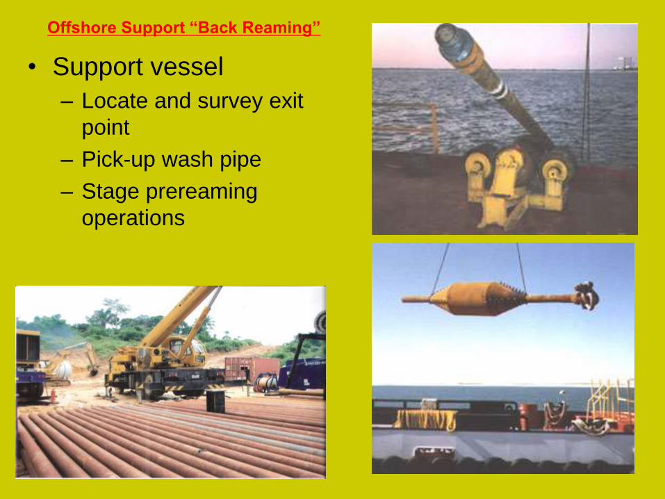
Offshore Support “Back Reaming”
• Support vessel
– Locate and survey exit
point
– Pick-up wash pipe
– Stage prereaming
operations
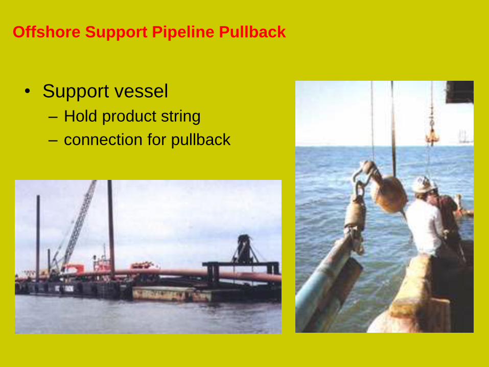
Offshore Support Pipeline Pullback
• Support vessel
– Hold product string
– connection for pullback

Intercept Drilling
• Concept developed from oilfield technology for
tapping into capped wells.
• Requirements
– Two HDD Maxi Rigs
– Insert Casings at each Drill Site.
– Drill from one side to within a notional 500m of the
opposed rig
– Drill from the opposed side to intercept the first drill

HDD Intercept Drilling
• Restrictions
–Ground Conditions (Rock, Stiff clays)
–Depth of Geotechnical Survey
–New
–Repeatability.

INSTALLATION METHODOLOGY FOR INTERCEPT CROSSINGS
• Mobilize Equipment and Personnel to Site.
• Survey and re-establish entry and exit co-ordinates.
• Set up Equipment at both sides of the River (Rig, mud unit and
Steering Tool and wire coils).
• Install casing in alignment to entry angles to firm ground bed at both
sides.
• Drill 2nos Pilot holes into the intersect area, from both sides of the
river.
• Switch the Guidance system on the shorter crossing to the Passive
Magnetic ranging system (PMRS) mode and establish contact
between both guidance systems.
• Retrieve the short crossing as the longer crossing is steered into the
same hole as the shorter crossing, using the PMRS as a homing
device to the exit point.
• Disconnect both guidance systems.
• Connect a reamer and commence the hole expansion process

My Various Site HDD Experiences
• 24” X 1.5Km River Niger Crossing At Kwale For Daewoo/NAOC In
March Of 2004 Using 300Ton (625,000#) American Augers Rig
• 40” X 760M Road & Creek Crossing For Daewoo/SPDC In January
201O Using The 300Ton American Augers Rig.
• 18” X 1.3KM Uruan River Crossing at Uruan, Akwa-Ibom State.
(swamp)
• 18” x 950m Aka-Ibonda River crossing at Creek Town, Cross River
state. (swamp)
• 18” x 704m Calabar River Crossing at Calabar. (land)
• 18” x 650m Itu River Crossing, C.River State. (swamp)
• 18” x 550m Esu and Esukudo River crosings, CRS. (swamp)
• 18” x 363m Abak river Crossing, Aks. (land)

My Various Site HDD Experiences
30” x 300m Road Xing – Zakhem Constr Ltd (October 2011)
12” x 300m Liverpool River Xing – Oando Plc (September 2011)
Test Pilot Hole Bore, 300m – Oando Plc (August 2011)
Installation Period: November 2011
24” X 1.7km Oron River Crossing
24” x 1.2km Uruan River Crossing
24” x 950m Calabar River Crossing
24” x 650m Itu River Crossing
24” x 600m Esu River crossing
Client – NIPP/KAZTEC
Status– Swamp Site Preparations and Mobilization
Installation Period – 2nd
Quarter 2012
16”,6” and 4” X 700m Mid-Stream, Bundle Crossing across
Commodore Channel Lagos.
Method – HDD, Shore Approach.
Client – Oando Plc
Status – Engineering and Design Completed

HDD EQUIPMENT & CREW WORKED WITH
RIG – AMERICAN AUGERS DD625 HDD RIG (2004)
CAPABILITY – 300 TON (625,000 LB) PULL BACK
CAPABILITY (CAPABLE OF PULLING 3.5KM X 12” P/L)
PUMP/CLEANING SYSTEM – TULSA RIG IRON 10,000
GALLONS MUD CLEANING / RECYCLING SYSTEM
750GPM WEATHERFORD T425 MUD PUMP
6” SYKES TRASH PUMPS (3 NOS).
3KM 6-5/8” FH DRILL PIPES.
VARIOUS SIZES OF FLY CUTTERS/HOLE OPENERS AND
BARREL REAMERS Frm 12” to 60”.
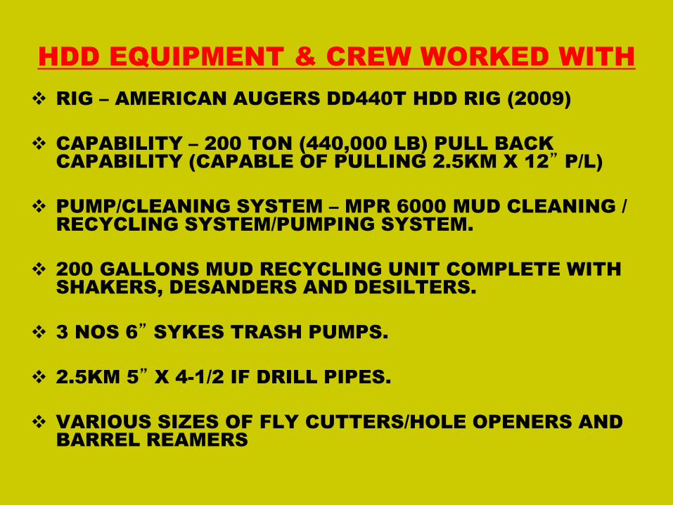
HDD EQUIPMENT & CREW WORKED WITH
RIG – AMERICAN AUGERS DD440T HDD RIG (2009)
CAPABILITY – 200 TON (440,000 LB) PULL BACK
CAPABILITY (CAPABLE OF PULLING 2.5KM X 12” P/L)
PUMP/CLEANING SYSTEM – MPR 6000 MUD CLEANING /
RECYCLING SYSTEM/PUMPING SYSTEM.
200 GALLONS MUD RECYCLING UNIT COMPLETE WITH
SHAKERS, DESANDERS AND DESILTERS.
3 NOS 6” SYKES TRASH PUMPS.
2.5KM 5” X 4-1/2 IF DRILL PIPES.
VARIOUS SIZES OF FLY CUTTERS/HOLE OPENERS AND
BARREL REAMERS
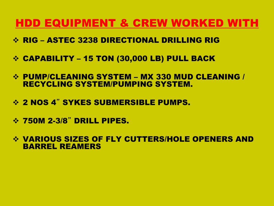
HDD EQUIPMENT & CREW WORKED WITH
RIG – ASTEC 3238 DIRECTIONAL DRILLING RIG
CAPABILITY – 15 TON (30,000 LB) PULL BACK
PUMP/CLEANING SYSTEM – MX 330 MUD CLEANING /
RECYCLING SYSTEM/PUMPING SYSTEM.
2 NOS 4” SYKES SUBMERSIBLE PUMPS.
750M 2-3/8” DRILL PIPES.
VARIOUS SIZES OF FLY CUTTERS/HOLE OPENERS AND
BARREL REAMERS

The Benefits of Directional Drilling
• Minimum environmental disturbance
• No interruption to shipping, road or rail traffic
• Accurate installation
• Shorter construction schedules
• Lower installation costs
• Minimal maintenance
• Greater protection from external damage
• Requires no concrete coating.
• Cheaper alternative to open cut.
• Less logistics
• Can be buried up to 30mtrs, hence out of
the reach of vandals.
• Fewer personnel.
• Depth of cover add as additional
protection to the pipe.
• Accurate As-Built Documentation.
The Benefits of Directional Drilling cont.

THANK YOU
FOR
LISTENING