Demontare Steering Column Modul
15
94 - 9 Steering Column Switches General information Caution! When disconnecting and reconnecting battery terminals, observe all applicable Notes and torque specifications, as well as instructions on performing OBD program and electrical system function checks as specified in this Repair Manual 27 - 4, Battery, disconnecting and reconnecting . The function of the steering column switches are integrated with the Steering Column Electronic Systems Control Module J527 . Note: After installing a new Steering Column Electronic Systems Control Module J527 , it must be coded 94 - 9, Steering Column Electronic Systems Control Module J527 , coding . If malfunctions occur at steering column switch, coding of Steering Column Electronic Systems Control Module J527 must be checked using Output Diagnostic Test Mode (DTM) 94 - 9, Steering Column Electronic Systems Control Module J527 , performing Output Diagnostic Test Mode (DTM) . Note: Additional information: Owners Manual Self Study Program - Course Number 891503 "The 2006 Passat Introduction" Self Study Program - Course Number 871503 "The 2006 Passat Electrical Systems Design and Function" Electrical Wiring Diagrams, Troubleshooting and Component Locations binder CAN-Bus wire repairs 97 - 8, Repairing CAN - Bus wires On Board Diagnostic (OBD), function Стр. 1 из 15 Volkswagen Passat B6 2005 - Steering Column Switches
-
Upload
diana-nechifor -
Category
Documents
-
view
275 -
download
6
Transcript of Demontare Steering Column Modul
94 - 9
Steering Column Switches
General information
Caution!
When disconnecting and reconnecting battery terminals, observe all applicable Notes and torque specifications, as well as instructions on performing OBD program and electrical system function checks as specified in this Repair Manual 27-4, Battery, disconnecting and reconnecting .
The function of the steering column switches are integrated with the Steering Column Electronic Systems Control Module J527 .
Note:
After installing a new Steering Column Electronic Systems Control Module J527 , it must be coded 94-9, Steering Column Electronic Systems Control Module J527 , coding .
If malfunctions occur at steering column switch, coding of Steering Column Electronic Systems Control Module J527 must be checked using Output Diagnostic Test Mode (DTM) 94-9, Steering Column Electronic Systems Control Module J527 , performing Output Diagnostic Test Mode (DTM) .
Note:
Additional information:
Owners Manual
Self Study Program - Course Number 891503 "The 2006 Passat Introduction"
Self Study Program - Course Number 871503 "The 2006 Passat Electrical Systems Design and Function"
Electrical Wiring Diagrams, Troubleshooting and Component Locations binder
CAN-Bus wire repairs 97-8, Repairing CAN-Bus wires
On Board Diagnostic (OBD), function
Стр. 1 из 15 Volkswagen Passat B6 2005 - Steering Column Switches
The Steering Column Electronic Systems Control Module J527 has On Board Diagnostic (OBD) capabilities which aids in troubleshooting.
For troubleshooting, use Vehicle Diagnostic, Testing and Information System VAS 5051/5052 in operating mode "Guided Fault Finding" .
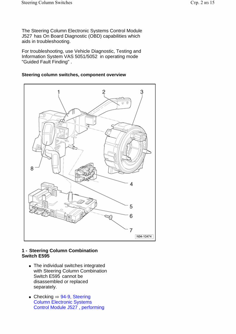
Steering column switches, component overview
1 - Steering Column Combination Switch E595
The individual switches integrated with Steering Column Combination Switch E595 cannot be disassembled or replaced separately.
Checking 94-9, Steering Column Electronic Systems Control Module J527 , performing
Стр. 2 из 15Steering Column Switches

Output Diagnostic Test Mode (DTM)
2 - Windshield Wiper/Washer Switch E22
Component of Steering Column Combination Switch E595 94-9, Steering Column Combination Switch E595
Checking 94-9, Steering Column Electronic Systems Control Module J527 , performing Output Diagnostic Test Mode (DTM)
3 - Airbag Spiral Spring/Return Spring With Slip Ring F138
Removing and installing 94-9, Airbag Spiral Spring/Return Spring With Slip Ring F138 , removing and installing
4 - Steering Angle Sensor G85
Removing and installing 94-9, Steering Angle Sensor G85 , removing and installing
5 - Cruise Control Switch E45
Component of Steering Column Combination Switch E595 94-9, Steering Column Combination Switch E595
Checking 94-9, Steering Column Electronic Systems Control Module J527 , performing Output Diagnostic Test Mode (DTM)
6 - Steering Column Electronic Systems Control Module J527
Removing and installing 94-9, Steering Column Electronic Systems Control Module J527 , removing and installing
Coding 94-9, Steering Column Electronic Systems Control Module J527 , coding
Стр. 3 из 15Steering Column Switches
Output Diagnostic Test Mode (DTM) 94-9, Steering Column Electronic Systems Control Module J527 , performing Output Diagnostic Test Mode (DTM)
7 - Screw (T7)
8 - Turn Signal Switch E2
Component of Steering Column Combination Switch E595 94-9, Steering Column Combination Switch E595
Checking 94-9, Steering Column Electronic Systems Control Module J527 , performing Output Diagnostic Test Mode (DTM)
Steering column switches, removing and installing
Warning!
Special safety precautions apply to vehicles equipped with airbags
Repair Manual, Body Interior, Repair Group 69, Airbag, CAUTIONS and WARNINGS
Caution!
When disconnecting and reconnecting battery terminals, observe all applicable Notes and torque specifications, as well as instructions on performing OBD program and electrical system function checks as specified in this Repair Manual 27-4, Battery, disconnecting and reconnecting .
Removing:
Should only an individual component of the steering column switch assembly be removed or replaced, the following sequence must always be followed.
- Disconnect battery 27-4, Battery, disconnecting and reconnecting .
- Remove steering wheel
Стр. 4 из 15Steering Column Switches
.
Repair Manual, Body Interior, Repair Group 69, Airbag
- Remove steering column trim
.
Repair Manual, Body Interior, Repair Group 68, storage compartments, covers and panels; removing and installing steering column trim
Remove steering column switch assembly components in the following sequence:
Steering Column Electronic Systems Control Module J527 94-9, Steering Column Electronic Systems Control Module J527 , removing and installing
Airbag Spiral Spring/Return Spring With Slip Ring F138 94-9, Airbag Spiral Spring/Return Spring With Slip Ring F138 , removing and installing
Steering Angle Sensor G85 94-9, Steering Angle Sensor G85
Steering Column Combination Switch E595 94-9, Steering Column Combination Switch E595 , removing and installing
Installing:
Install in reverse order of removal.
Steering Column Electronic Systems Control Module J527
Steering Column Electronic Systems Control Module J527 , removing and installing
Note:
After installing a new control module, it must be coded 94-9, Steering Column Electronic Systems Control Module J527 , coding .
Стр. 5 из 15Steering Column Switches

If malfunctions occur at steering column switch, coding of control module must be checked 94-9, Steering Column Electronic Systems Control Module J527 , coding .
Removing:
- Disconnect battery 27-4, Battery, disconnecting and reconnecting .
- Remove steering wheel
.
Repair Manual, Body Interior, Repair Group 69, Airbag
- Remove steering column trim
.
Repair Manual, Body Interior, Repair Group 68, storage compartments, covers and panels; removing and installing steering column trim
- Remove screw - 2 - at Steering Column Electronic Systems Control Module J527 - 1 - .
Стр. 6 из 15Steering Column Switches
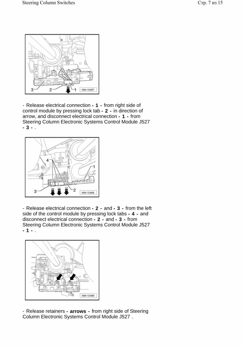
- Release electrical connection - 1 - from right side of control module by pressing lock tab - 2 - in direction of arrow, and disconnect electrical connection - 1 - from Steering Column Electronic Systems Control Module J527 - 3 - .
- Release electrical connection - 2 - and - 3 - from the left side of the control module by pressing lock tabs - 4 - and disconnect electrical connection - 2 - and - 3 - from Steering Column Electronic Systems Control Module J527 - 1 - .
- Release retainers - arrows - from right side of Steering Column Electronic Systems Control Module J527 .
Стр. 7 из 15Steering Column Switches

- Release retainers - arrow - from left side of Steering Column Electronic Systems Control Module J527 .
- Carefully pull Steering Column Electronic Systems Control Module J527 downward from Steering Column Combination Switch E595 .
Note:
The electrical connections between the Airbag Spiral Spring/Return Spring With Slip Ring F138 and segment sensor are disconnected automatically when the components are separated.
- Release electrical connection - 1 - by pulling locking tab - arrow A - and pulling connection - 1 - from Steering Column Electronic Systems Control Module J527 .
- Disengage lock - 3 - on electrical connection - 2 - .
- Disengage lock - arrow B - on electrical connection - 2 - and disconnect from Steering Column Electronic Systems Control Module J527 .
Installing:
Install in reverse order of removal, noting the following:
Стр. 8 из 15Steering Column Switches

Note:
Ensure that no electrical pins are bent and that the connections engage audibly when reconnecting.
Steering Column Electronic Systems Control Module J527 , coding
- Connect Vehicle Diagnostic, Testing and Information System VAS 5051/5052 97-1, Vehicle Diagnostic, Testing and Information System VAS 5051/5052 , connecting and selecting functions .
- In Vehicle Diagnostic, Testing and Information System VAS 5051/5052 , select operating mode "Guided Fault Finding" .
- Using the "Go To" button, select "Functions/Component selection" and the following menu options in sequence:
Body
Electrical Equipment
01 - On Board Diagnostic (OBD) capable systems
Steering wheel electronics
Functions of steering wheel electronics
Code Control Module for steering wheel electronics
Steering Column Electronic Systems Control Module J527 , performing Output Diagnostic Test Mode (DTM)
- Connect Vehicle Diagnostic, Testing and Information System VAS 5051/5052 97-1, Vehicle Diagnostic, Testing and Information System VAS 5051/5052 , connecting and selecting functions .
- In Vehicle Diagnostic, Testing and Information System VAS 5051/5052 , select operating mode "Guided Fault Finding" .
- Using the "Go To" button, select "Functions/Component selection" and the following menu options in sequence:
Body
Стр. 9 из 15Steering Column Switches

Electrical Equipment
01 - On Board Diagnostic (OBD) capable systems
Steering wheel electronics
Functions of steering wheel electronics
Output Diagnostic Test Mode (DTM) of steering wheel electronics
Airbag Spiral Spring/Return Spring With Slip Ring F138
Airbag Spiral Spring/Return Spring With Slip Ring F138 , removing and installing
Removing:
- Disconnect battery 27-4, Battery, disconnecting and reconnecting .
Remove the following components in order:
- Remove steering wheel
.
Repair Manual, Body Interior, Repair Group 69, Airbag
- Remove steering column trim
.
Repair Manual, Body Interior, Repair Group 68, storage compartments, covers and panels; removing and installing steering column trim
- Remove Steering Column Electronic Systems Control Module J527 94-9, Steering Column Electronic Systems Control Module J527 , removing and installing .
Caution!
When removing, the spiral spring must not be twisted out of the center position and wheels must be in the "straight ahead position"
Стр. 10 из 15Steering Column Switches

- Lift both retainers - arrows - on Airbag Spiral Spring/Return Spring With Slip Ring F138 - 1 - slightly and pull Airbag Spiral Spring/Return Spring With Slip Ring F138 towards rear from steering column.
Installing:
Install in reverse order of removal, noting the following:
Note:
When installing spiral spring, spiral spring must be in center position and wheels must be in the "straight ahead position" .
Ensure retainers are fully engaged.
The following depicts center position of spiral spring, which is dependent on the manufacturer:
The color marked (black square) band - arrow - must be located in viewing window - 1 - .
Стр. 11 из 15Steering Column Switches

The color marked (yellow) band - arrow - must be located in viewing window - 1 - .
Steering Angle Sensor G85
Steering Angle Sensor G85 , removing and installing
Removing:
- Disconnect battery 27-4, Battery, disconnecting and reconnecting .
Remove the following components in order:
- Remove steering wheel
.
Repair Manual, Body Interior, Repair Group 69, Airbag
- Remove steering column trim
.
Repair Manual, Body Interior, Repair Group 68, storage compartments, covers and panels; removing and installing steering column trim
- Remove Steering Column Electronic Systems Control Module J527 94-9, Steering Column Electronic Systems Control Module J527 , removing and installing .
- Remove Airbag Spiral Spring/Return Spring With Slip Ring F138 94-9, Airbag Spiral Spring/Return Spring With Slip Ring F138 , removing and installing .
Стр. 12 из 15Steering Column Switches
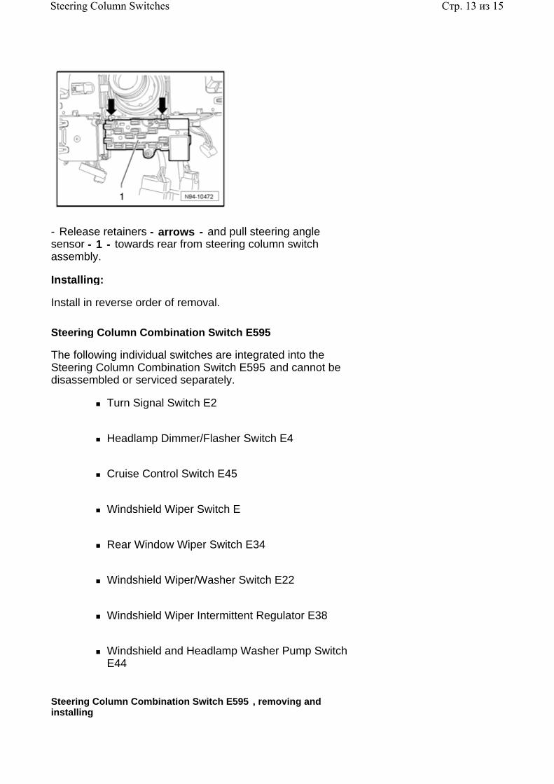
- Release retainers - arrows - and pull steering angle sensor - 1 - towards rear from steering column switch assembly.
Installing:
Install in reverse order of removal.
Steering Column Combination Switch E595
The following individual switches are integrated into the Steering Column Combination Switch E595 and cannot be disassembled or serviced separately.
Turn Signal Switch E2
Headlamp Dimmer/Flasher Switch E4
Cruise Control Switch E45
Windshield Wiper Switch E
Rear Window Wiper Switch E34
Windshield Wiper/Washer Switch E22
Windshield Wiper Intermittent Regulator E38
Windshield and Headlamp Washer Pump Switch E44
Steering Column Combination Switch E595 , removing and installing
Стр. 13 из 15Steering Column Switches
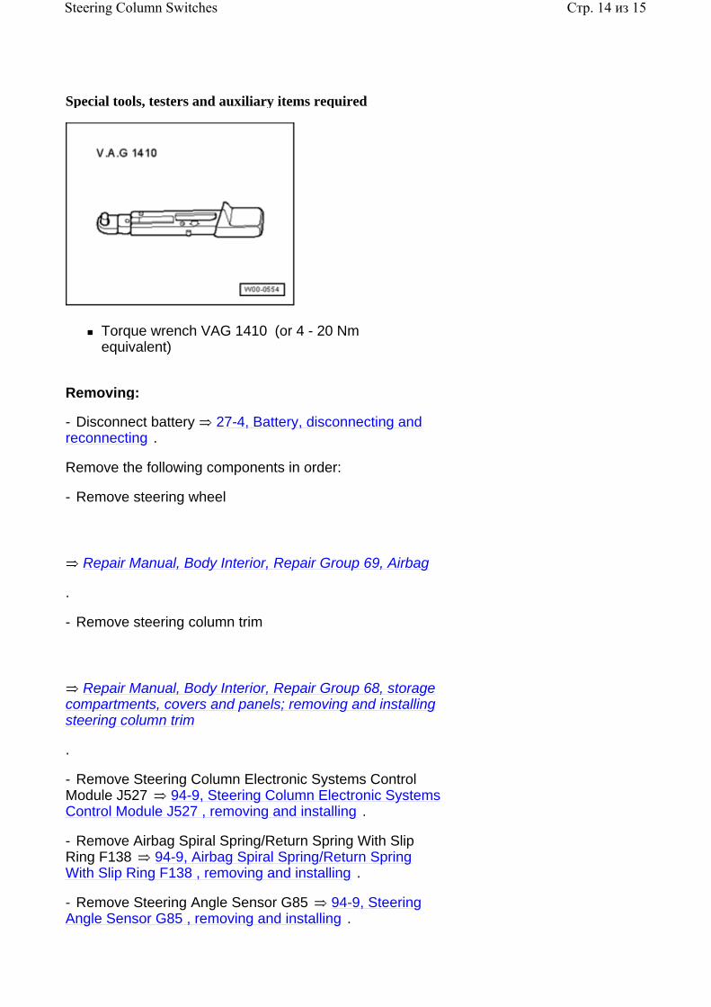
Special tools, testers and auxiliary items required
Torque wrench VAG 1410 (or 4 - 20 Nm equivalent)
Removing:
- Disconnect battery 27-4, Battery, disconnecting and reconnecting .
Remove the following components in order:
- Remove steering wheel
.
Repair Manual, Body Interior, Repair Group 69, Airbag
- Remove steering column trim
.
Repair Manual, Body Interior, Repair Group 68, storage compartments, covers and panels; removing and installing steering column trim
- Remove Steering Column Electronic Systems Control Module J527 94-9, Steering Column Electronic Systems Control Module J527 , removing and installing .
- Remove Airbag Spiral Spring/Return Spring With Slip Ring F138 94-9, Airbag Spiral Spring/Return Spring With Slip Ring F138 , removing and installing .
- Remove Steering Angle Sensor G85 94-9, Steering Angle Sensor G85 , removing and installing .
Стр. 14 из 15Steering Column Switches

- Remove both screws - arrows - from upper steering column switch assembly.
- Pull steering switch assembly towards rear from steering column.
Installing:
Install in reverse order of removal.
- Torque all fasteners according to value in table 94-12, Lights, Switches - Exterior, tightening torques .
Steering Column Combination Switch E595 , checking
Note:
If malfunctions occur at steering column switch, coding of Steering Column Electronic Systems Control Module J527 must be checked using Output Diagnostic Test Mode (DTM) 94-9, Steering Column Electronic Systems Control Module J527 , performing Output Diagnostic Test Mode (DTM) .
Стр. 15 из 15Steering Column Switches