DEMONSTRATING THE POTENTIAL OF FAR … · Due to its much smaller overturning moments, Ampyx Power...
18
Visualisation of offshore floating wind park with multiple Airborne Wind Energy systems Public Summary The Sea-Air-Farm Project Demonstrating the potential of far offshore floating airborne wind farms
Transcript of DEMONSTRATING THE POTENTIAL OF FAR … · Due to its much smaller overturning moments, Ampyx Power...
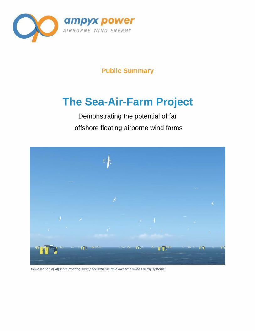
Visualisation of offshore floating wind park with multiple Airborne Wind Energy systems
Public Summary
The Sea-Air-Farm Project
Demonstrating the potential of far
offshore floating airborne wind farms

SEA-AIR-FARM PROJECT 2
1. Executive Summary
Ampyx Power’s Airborne Wind Energy System (AWES) generates electricity from wind using an
aircraft flying 500m high. Due to its small overturning moments, AWES could be deployed in
deep water on small anchored floating platforms.
In the Sea-Air-Farm project, a consortium with Ampyx Power, ECN (Energy Research Centre
Netherlands), Marin (Maritime Research Institute Netherlands) and Mocean Offshore
researched the offshore application of one floating AWES and the possibilities and limitations of
an entire airborne wind park with multiple systems, far-offshore and in deep waters.
The project research indicated that such a wind farm seems possible and competitive. In the
following pages, the results are described in more detail.
Consortium partners and sponsors of the Sea-Air-Farm project.
SEA-AIR-FARM PROJECT 3
2. What is Airborne Wind Energy?
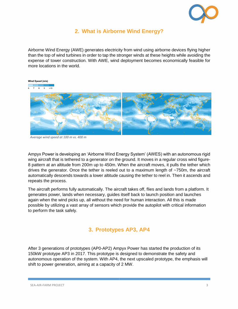
Airborne Wind Energy (AWE) generates electricity from wind using airborne devices flying higher
than the top of wind turbines in order to tap the stronger winds at these heights while avoiding the
expense of tower construction. With AWE, wind deployment becomes economically feasible for
more locations in the world.
Average wind speed at 100 m vs. 400 m
Ampyx Power is developing an ‘Airborne Wind Energy System’ (AWES) with an autonomous rigid
wing aircraft that is tethered to a generator on the ground. It moves in a regular cross wind figure-
8 pattern at an altitude from 200m up to 450m. When the aircraft moves, it pulls the tether which
drives the generator. Once the tether is reeled out to a maximum length of ~750m, the aircraft
automatically descends towards a lower altitude causing the tether to reel in. Then it ascends and
repeats the process.
The aircraft performs fully automatically. The aircraft takes off, flies and lands from a platform. It
generates power, lands when necessary, guides itself back to launch position and launches
again when the wind picks up, all without the need for human interaction. All this is made
possible by utilizing a vast array of sensors which provide the autopilot with critical information
to perform the task safely.
3. Prototypes AP3, AP4
After 3 generations of prototypes (AP0-AP2) Ampyx Power has started the production of its
150kW prototype AP3 in 2017. This prototype is designed to demonstrate the safety and
autonomous operation of the system. With AP4, the next upscaled prototype, the emphasis will
shift to power generation, aiming at a capacity of 2 MW.

SEA-AIR-FARM PROJECT 4
4. Why floating Airborne Wind Energy?
The availability of sites for conventional off-shore wind parks will become increasingly scarce in
the future. This calls for expansion of the operating envelope of wind power technologies. The
availability of sites is currently very much restricted to shallow waters. The cost of offshore wind
power increases significantly with water depth, due to the increased costs of foundation works
either bottom-fixed or floating. Due to its much smaller overturning moments, Ampyx Power
AWES could be deployed on relatively small anchored floating platforms, allowing economical
deployment of AWES in places where deployment of conventional offshore wind turbines is
economically or technically impossible.
5. Sea-Air-Farm project
In August 2016 the Dutch ministry of Economic Affairs (RVO) granted subsidy to research the
floating application of the Ampyx Power AWES under the TKI-WOZ R&D program. A project
consortium with ECN (Energy Research Centre Netherlands), Marin (Maritime Research Institute
Netherlands) and Mocean Offshore was formed to contribute to the technology development of
floating AWES based on Ampyx Power’s prototype AP4, and to explore the possibilities and
limitations of an entire airborne windfarm with multiple systems, far-offshore and in deep waters.
ECN validated the aerodynamic tools, modelled installation and O&M scenarios, and calculated
the yield and costs. Mocean Offshore designed the floating platform, which was tested in
Marin’s test basin. Ampyx Power conceptually designed the AP4 aircraft and the entire offshore
windfarm, studied the certification framework and managed the project.
Floating Airborne Wind Energy System Ampyx Power

SEA-AIR-FARM PROJECT 5
6. Third party aerodynamic model validation and integration
ECN validated Ampyx Power’s aerodynamic models. First, they compared the results from two
open-source ‘Computational Fluid Dynamics’ (CFD) solvers with different modeling approaches.
Ampyx Power uses a pressure-based solver ‘OpenFOAM’ to calculate the 2D and 3D
aerodynamic performance of their aircrafts, while ECN compares these results with the CFD
solution from a density-based solver ‘SU2’, developed for wind turbine technology. The
comparison indicates extremely good agreements between the two codes in 2D. This sets a
high level of confidence on the generated results. The 3D results from both codes show a good
agreement on the force distribution along the aircraft, while achieving <20% difference in the
total aerodynamic forces. Further investigation is required to identify the cause of this
discrepancy. Overall, this verification study clearly shows the advancement in CFD to achieve
an independent solution despite the different methods, and provides an in-depth understanding
of the complex flow field around the aircraft and tether.
Second step was for ECN to evaluate the power generated using a free vortex wake model
coupled to the lifting line model, named Aerodynamic Windturbine Simulation Module (AWSM),
one of ECN’s software packages containing state-of-the-art aerodynamic models originally
developed for horizontal axis wind turbines. In this framework, AWSM is used to calculate the
aerodynamic forces generated by the aircraft and from there, deduce the power production at
different wind speeds. The results provided by AWSM are verified against the simulations of a
higher fidelity, but more computationally expensive computational fluid dynamics (CFD) code. The
comparison shows a good agreement between the two approaches, confirming that relatively
simple and efficient free vortex wake codes, like AWSM, can be used to obtain an accurate
estimation of power generated by AWES.
CFD model
SEA-AIR-FARM PROJECT 6
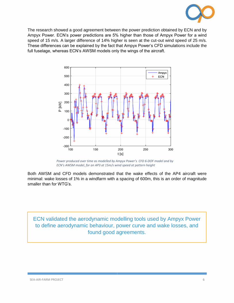
The research showed a good agreement between the power prediction obtained by ECN and by
Ampyx Power. ECN’s power predictions are 5% higher than those of Ampyx Power for a wind
speed of 15 m/s. A larger difference of 14% higher is seen at the cut-out wind speed of 25 m/s.
These differences can be explained by the fact that Ampyx Power’s CFD simulations include the
full fuselage, whereas ECN’s AWSM models only the wings of the aircraft.
Both AWSM and CFD models demonstrated that the wake effects of the AP4 aircraft were
minimal: wake losses of 1% in a windfarm with a spacing of 600m, this is an order of magnitude
smaller than for WTG’s.
Power produced over time as modelled by Ampyx Power’s CFD 6-DOF model and by ECN’s AWSM model, for an AP3 at 15m/s wind speed at pattern height
ECN validated the aerodynamic modelling tools used by Ampyx Power
to define aerodynamic behaviour, power curve and wake losses, and
found good agreements.

SEA-AIR-FARM PROJECT 7
7. Conceptual Design AP-4
The project is based on the performance of Ampyx Power’s AP3 design scaled-up to 2 MW cycle
power size. Such an aircraft would have a span width of 36m and a weight of 3.5 Metric Tonnes,
while the launch and land platform would measure around 20 x 30m.
However, a mere scaling of AP3 would not per se result in optimal performance, and hence Ampyx
Power explored a range of design optimizations for the various sub-systems. They assessed the
ability to follow optimal power production trajectories for different patterns, the pattern size and
heights and tether lengths. This resulted in the identification of a number of considerations, which
will be discussed below.
Indicative dimensions of AP4’s 2 MW aircraft on the launch and land platform.

SEA-AIR-FARM PROJECT 8
Optimal tether Reel-in and Reel-Out Speed over time (seconds) for lemniscate trajectory at 12 m/s wind speed at pattern height.
A combination of high-lift and high controllability is not obvious and becomes more critical as the
aircraft size increases. While the size of the plane substantially triples from 12m wing span for
AP3 to around 36m for AP4, the vertical space in which the aircraft flies its power production
patterns does not increase. It becomes more and more important to fully optimize its configuration,
roll behavior, and control effectiveness, all in relation to an optimal flight pattern for power
production. The existing suite of aerodynamic tools does not provide the answers, and Ampyx
Power has come to the conclusion that the best way to make progress in this complex field is
through testing small scale models from various aircraft lay-outs at high velocities and under a
wide operational envelope. Testing in water basins is an interesting option to explore, as it would
allow to test small models at high relative velocities, while maintaining the correct Reynold figures.
The impact of the flying speed of the aircraft, in combination with the reel-in and reel-out speed
of the tether was also assessed. The challenge will be for the integrated systems of generator,
drive train, winch and tether to meet the speed requirements.
Illustration of the lemniscate trajectory at wind speeds of 6m/s (left) and 25m/s (right) at pattern height.

SEA-AIR-FARM PROJECT 9
3D visualization of the interference with platforms of approximately 350m apart.
Main issues in the scaling are: the increased inertia of the drum, the heat production within the
tether during repetitive bending over sheaves, slippage of the tether over the sheaves and
drum, and the efficiency of the drive train/generator over the entire range of the cycle.
Innovative solutions that can overcome these challenges have been identified; however, they
should be further worked out and de-risked by building and testing partial prototypes
(breadboards).
Within an AWES windfarm, multiple aircrafts will fly simultaneously within each other’s zone of
operation. Model testing demonstrated that Ampyx Power’s control strategies have the potential
to enable synchronous flights from a spacing of around 350m. Such flying requires a window of
only a few seconds to correct any deviation from the prescribed pattern and to avoid contact
with the neighbor’s plane or tether. The control system is accurate enough to match this
requirement. However, remaining issues still to be investigated are: how to deal with wind shifts
over the windfarm, how to deal with emergencies (such as tether release), and how to
smoothen the park power output.
The modelling of 2MW system, including aircraft, tether and winch hinted
to a number of scaling challenges with respect to the controllability of the
aircraft and efficient mechanical power transfer. Solutions exist, but need
to be worked out and validated.
Model testing
demonstrated that
Ampyx Power’s
control strategies
have the potential to
enable synchronous
flights from a spacing
of around 350m, with
a tether length of up
to 750m.
SEA-AIR-FARM PROJECT 10
8. Floating Platform design
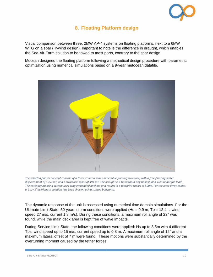
Visual comparison between three, 2MW AP-4 systems on floating platforms, next to a 6MW
WTG on a spar (Hywind design). Important to note is the difference in draught, which enables
the Sea-Air-Farm solution to be towed to most ports, contrary to the spar design.
Mocean designed the floating platform following a methodical design procedure with parametric
optimization using numerical simulations based on a 9-year metocean datafile.
The dynamic response of the unit is assessed using numerical time domain simulations. For the
Ultimate Limit State, 50-years storm conditions were applied (Hs = 9.9 m, Tp = 12.4 s, wind
speed 27 m/s, current 1.8 m/s). During these conditions, a maximum roll angle of 23° was
found, while the main deck area is kept free of wave impacts.
During Service Limit State, the following conditions were applied: Hs up to 3.5m with 4 different
Tps, wind speed up to 15 m/s, current speed up to 0.8 m. A maximum roll angle of 12° and a
maximum lateral offset of 7 m were found. These motions were substantially determined by the
overturning moment caused by the tether forces.
The selected floater concept consists of a three-column semisubmersible floating structure, with a free-floating water displacement of 1259 mt, and a structural mass of 491 mt. The draught is 11m without any ballast, and 16m under full load. The catenary mooring system uses drag embedded anchors and results in a footprint radius of 500m. For the inter array cables, a ‘Lazy S’ overlength solution has been chosen, using subsea buoyancy.

SEA-AIR-FARM PROJECT 11
Array cable loads have been derived from the simulations and pass the acceptance criteria
(100kN compression and .48rad/m bending).
During the project, Marin performed scale model tests, which provide an accurate indication of
the damping coefficients of the platform. A calibration study of Mocean’s numerical models
showed that the damping of the model tests is higher than used in the numerical simulations, the
results can therefore be interpreted as conservative.
A section of 10 units was modelled in a 3D environment to ensure that no contact occurs between
the unsupported part of the array cable and the mooring lines under various extreme conditions.
Mocean analysed both the production costs and the installation costs for various scenarios for
the load out, ballasting, transport and installation of the units. The results form the basis of ECN’s
installation modelling. Key in the logistics analysis is the limited draught of only 11m in unballasted
conditions; however, (partial) ballasting is required to increase stability before going offshore.
Ampyx Power explored the landing of its aircraft on Mocean’s platform design. The landing
modelling integrated Ampyx Power’s landing algorithms, platform movements due to waves, and
plane movements due to gusts, all modelled in Monte-Carlo simulations from the 9-years
Comparison of the costs/MW of Mocean’s AP4-floater to the costs for a comparable WTG-floater. As it is the survival conditions of the platform that are driving the design, and not the weight or forces from the AWES. So, future scaling up will hardly affect the weight or cost of the floater.
SEA-AIR-FARM PROJECT 12
Buchan Deep metocean wind and wave dataset. The results showed that the limiting factor in
safe landing are the wind gusts rather than the platform movements. While the platform dampens
out the relatively small high-frequency movements, the larger platform movements are at such a
low frequencies that the aircraft’s landing algorithms can correct for it.
The low initial draught of around 11m is a unique selling point for this floater, as it allows most
ports to serve as marshalling harbor - contrary to most of the floating competition. The main aim
for another future design iteration should be to further reduce the draught / increase the stability
before ballasting. (Also the limited height of the system consist of a competitive advantage, as it
allows production behind bridges)
Based on the initial assumptions, it was concluded that a soft mooring would be the best option.
Considering the considerable horizontal movement during power generation, the environmental
impact of the mooring chains, and having reduced the assumption of the distance between
facilities (from around 700m to around 350m), it would be useful to re-assess the optimal mooring.
It may turn out that semi-taught foundations or even a Tension Leg Platform (TLP) is a competitive
alternative.
Mocean’s design of the floater resulted in a semi-submersible platform
that fulfills all the requirements for a safe operation in offshore
conditions. The movements of the platform have considerably less
impact on landing than initially expected. Future design iterations will
lead to further optimization and considerable cost reductions. It is the
survival conditions of the platform that are driving the design, and not
the weight or forces from the AWES. So, future scaling up will hardly
affect the weight or cost of the floater.

SEA-AIR-FARM PROJECT 13
9. Marine modelling of the floating platform
The scale testing in the basin of Marin proved to add significant value to the existing design tools,
mainly because of the different scaling of the AP4 floater compared to other marine structures
that are much larger. Scaling and modelling the wave loading and mooring forces on floating
structures is common practice at Marin; however, for the simulation of the tether forces on the
platform, a novel system of 4 winches was designed, which jointly simulated the direction and
tension from the forces during power production.
The testing was successful and provided important feed-back on the validity and sensitivity of
several design parameters.
Floater in Marin's water basin

SEA-AIR-FARM PROJECT 14
Metocean conditions at the Buchan Deep site, as derived from the 9 years dataset
10. Deepwater wind farm design
In order to develop insights in the operations and costs of an entire AWES windfarm, a virtual
wind farm was designed. We selected the Buchan Deep site in the East of Scotland. An important
consideration was the fact that Statoil has built its Hywind offshore demonstrator on this location,
and hence a lot of environmental and soil data are available in the public domain. In addition, 9
years of wind and wave data have been purchased for the design, modelling and testing work of
all project partners.
Annual average wind speed
of 9.7 m/s at 400m altitude
Annual average significant
wave height of 1.75m
10 year maximum significant
wave height 9.5 m
Water depth around 100m
25km from Peterhead, taken
as marshalling harbour
SEA-AIR-FARM PROJECT 15
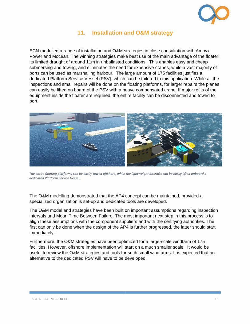
The entire floating platforms can be easily towed offshore, while the lightweight aircrafts can be easily lifted onboard a dedicated Platform Service Vessel.
11. Installation and O&M strategy
ECN modelled a range of installation and O&M strategies in close consultation with Ampyx
Power and Mocean. The winning strategies make best use of the main advantage of the floater:
its limited draught of around 11m in unballasted conditions. This enables easy and cheap
submersing and towing, and eliminates the need for expensive cranes, while a vast majority of
ports can be used as marshalling harbour. The large amount of 175 facilities justifies a
dedicated Platform Service Vessel (PSV), which can be tailored to this application. While all the
inspections and small repairs will be done on the floating platforms, for larger repairs the planes
can easily be lifted on board of the PSV with a heave compensated crane. If major refits of the
equipment inside the floater are required, the entire facility can be disconnected and towed to
port.
The O&M modelling demonstrated that the AP4 concept can be maintained, provided a
specialized organization is set-up and dedicated tools are developed.
The O&M model and strategies have been built on important assumptions regarding inspection
intervals and Mean Time Between Failure. The most important next step in this process is to
align these assumptions with the component suppliers and with the certifying authorities. The
first can only be done when the design of the AP4 is further progressed, the latter should start
immediately.
Furthermore, the O&M strategies have been optimized for a large-scale windfarm of 175
facilities. However, offshore implementation will start on a much smaller scale. It would be
useful to review the O&M strategies and tools for such small windfarms. It is expected that an
alternative to the dedicated PSV will have to be developed.
SEA-AIR-FARM PROJECT 16
12. Levelized Cost of Energy (LCoE)
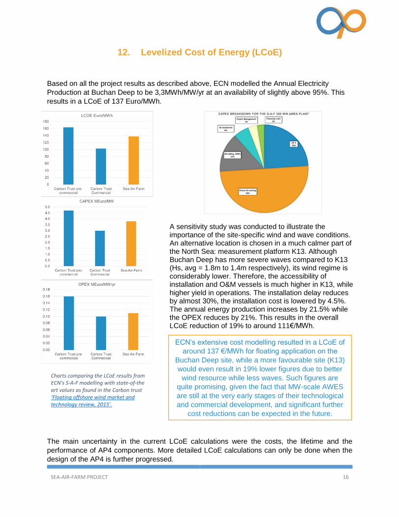
Based on all the project results as described above, ECN modelled the Annual Electricity
Production at Buchan Deep to be 3,3MWh/MW/yr at an availability of slightly above 95%. This
results in a LCoE of 137 Euro/MWh.
A sensitivity study was conducted to illustrate the importance of the site-specific wind and wave conditions. An alternative location is chosen in a much calmer part of the North Sea: measurement platform K13. Although Buchan Deep has more severe waves compared to K13 (Hs, avg = 1.8m to 1.4m respectively), its wind regime is considerably lower. Therefore, the accessibility of installation and O&M vessels is much higher in K13, while higher yield in operations. The installation delay reduces by almost 30%, the installation cost is lowered by 4.5%. The annual energy production increases by 21.5% while the OPEX reduces by 21%. This results in the overall LCoE reduction of 19% to around 111€/MWh.
The main uncertainty in the current LCoE calculations were the costs, the lifetime and the
performance of AP4 components. More detailed LCoE calculations can only be done when the
design of the AP4 is further progressed.
Charts comparing the LCoE results from ECN’s S-A-F modelling with state-of-the art values as found in the Carbon trust ‘Floating offshore wind market and technology review, 2015’.
ECN’s extensive cost modelling resulted in a LCoE of
around 137 €/MWh for floating application on the
Buchan Deep site, while a more favourable site (K13)
would even result in 19% lower figures due to better
wind resource while less waves. Such figures are
quite promising, given the fact that MW-scale AWES
are still at the very early stages of their technological
and commercial development, and significant further
cost reductions can be expected in the future.

SEA-AIR-FARM PROJECT 17
13. Certification
The project made an extensive inventory of all certifying bodies and authorities involved in flying
drones as well as floating devices, and their relevant guidelines and best practices. This review
confirmed that only some scattered and loose requirements exist, and there is nowhere a start
of any coherent framework.
In order to make a step forward in this, Ampyx Power has prepared a certification basis
proposal for AWES based on tethered drones (CS-AP), to be submitted for acceptance to the
European Aviation Safety Authority (EASA). Once accepted by EASA, we could make CS-AP
available as a starting point certification basis for all tethered drone developments. Therefore,
this specification can benefit the entire AWE community - and possibly beyond. Following expert
consultation, EASA may eventually turn it into a Special Condition or Certification Specification
for AWES.
This process has full support from Ampyx Power and EASA, however it is widely unknown
amongst the remaining stakeholders (SODM, RWS, ILT, Grid owners, certifying bodies, utilities,
insurers etc…). In order to gain broad acceptance of the CS-AP, an extensive consensus- and
awareness-building campaign is required.
In addition to the certification aspects, also the consenting framework for AWE is virtually non-
existing. Neither is the methodological framework to assess the environmental impact. As AWE
develops beyond the prototyping stages, a tremendous amount of work will need to be done in
this field.
All blue sub-systems are to be certified in compliance with European Aviation Safety Authority (EASA) regulations. The grey/yellow sub-systems will have different certification authorities.

SEA-AIR-FARM PROJECT 18
14. External Communication
All project partners have presented project results at a wide range of national and international
fora; copies of these presentations can be obtained from the respective partners. An animation
that visualizes the installation and operation of the offshore windfarm, can be found on Youtube.
ECN
Gabriele Bedon
Ashish Dewan
Mocean Offshore Technologies
Willem van Schooten
Marin
Rene Lindeboom
Ampyx Power
Bernard van Hemert