
Demco DM Gate Datasheets Oct2612
66
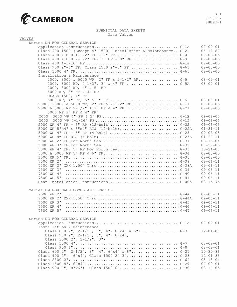
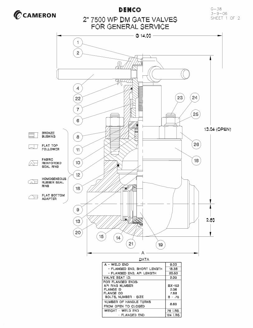
G-1 6-28-12 SHEET-1 SUBMITTAL DATA SHEETS Gate Valves VALVES Series DM FOR GENERAL SERVICE Application Instructions.....................................G-1A 07-09-01 Class 400-1500 (Except 4"-1500) Installation & Maintenance...G-2 06-12-87 Class 400 & 600 1-1/2" FP - 2" FP............................G-4 09-08-05 Class 400 & 600 2-1/2" FP, 3" FP - 8" RP .................... G-9 09-08-05 Class 400 4-1/16" FP ........................................ G-14 09-08-05 Class 900 2"-6" FP, Class 1500 2"-3" FP......................G-63 09-08-05 Class 1500 4" FP.............................................G-65 09-08-05 Installation & Maintenance 2000, 3000 & 5000 WP, 2" FP & 2-1/2" RP..................G-5 03-09-01 2000, 3000 WP, 2-1/2", 3" & 4" FP .......................G-5A 03-09-01 2000, 3000 WP, 4" & 5" RP 5000 WP, 3" FP & 4" RP CLASS 1500, 4" FP 5000 WP, 4" FP, 5" & 6" RP...............................G-6 03-09-01 2000, 3000, & 5000 WP, 2" FP & 2-1/2" RP.....................G-11 09-08-05 2000 & 3000 WP 2-1/2" & 3" FP & 4" RP, ......................G-21 09-08-05 5000 WP 3" FP & 4" RP 2000, 3000 WP 4" FP & 5" RP ................................. G-12 09-08-05 2000, 3000 WP 4-1/16" FP .................................... G-15 09-08-05 5000 WP 4" FP - 6" RP (12-bolt)..............................G-22 09-08-05 5000 WP 5"x4" & 6"x4" RTJ (12-bolt)..........................G-22A 01-31-11 5000 WP 4" FP - 6" RP (4-bolt) .............................. G-23 09-08-05 5000 WP 4” FP RTJ (4-bolt) .................................. G-23A 01-27-11 5000 WP 2" FP For North Sea..................................G-31 08-13-04 5000 WP 3" FP For North Sea..................................G-32 06-29-05 5000 WP 4" FP, 5" RP For North Sea...........................G-33 10-24-06 3000 & 5000 WP 5" FP & 6" RP.................................G-34 09-08-05 1000 WP 5" FP................................................G-35 09-08-05 7500 WP 2" ................................................. G-38 09-06-11 7500 WP 2" XXH 1.50” Thru ................................... G-38A 09-06-11 7500 WP 3" ................................................. G-39 09-06-11 7500 WP 4" ................................................. G-40 09-06-11 7500 WP 5" ................................................. G-41 09-06-11 Seat Installation Instructions...............................G-405 03-15-75 Series DM FOR NACE COMPLIANT SERVICE 7500 WP 2" ................................................. G-44 09-06-11 7500 WP 2" XXH 1.50” Thru ................................... G-44A 09-06-11 7500 WP 3" ................................................. G-45 09-06-11 7500 WP 4" ................................................. G-46 09-06-11 7500 WP 5" ................................................. G-47 09-06-11 Series DB FOR GENERAL SERVICE Application Instructions.....................................G-1A 07-09-01 Installation & Maintenance Class 600 2", 2-1/2", 3", 4", 6"x4" & 6";.................G-3 12-01-86 Class 900 2", 2-1/2", 3", 4", 6"x4"; Class 1500 2", 2-1/2", 3") Class 1500 4".............................................G-7 03-09-01 Class 900 6"..............................................G-8 03-09-01 Class 600 2", 2-1/2", 3", 4", 6"x4" & 6".....................G-27 10-30-86 Class 900 2" - 6"x4"; Class 1500 2"-3".......................G-28 12-01-86 Class 2500 2"................................................G-64 08-13-04 Class 1500 4", 6”x4”.........................................G-29 07-09-01 Class 900 6", 8"x6"; Class 1500 6"..........................G-30 03-16-05
Transcript of Demco DM Gate Datasheets Oct2612
G-1 6-28-12
SHEET-1
SUBMITTAL DATA SHEETS Gate Valves
VALVES Series DM FOR GENERAL SERVICE Application Instructions.....................................G-1A 07-09-01 Class 400-1500 (Except 4"-1500) Installation & Maintenance...G-2 06-12-87 Class 400 & 600 1-1/2" FP - 2" FP............................G-4 09-08-05 Class 400 & 600 2-1/2" FP, 3" FP - 8" RP .................... G-9 09-08-05 Class 400 4-1/16" FP ........................................ G-14 09-08-05 Class 900 2"-6" FP, Class 1500 2"-3" FP......................G-63 09-08-05 Class 1500 4" FP.............................................G-65 09-08-05 Installation & Maintenance 2000, 3000 & 5000 WP, 2" FP & 2-1/2" RP..................G-5 03-09-01 2000, 3000 WP, 2-1/2", 3" & 4" FP .......................G-5A 03-09-01 2000, 3000 WP, 4" & 5" RP 5000 WP, 3" FP & 4" RP CLASS 1500, 4" FP 5000 WP, 4" FP, 5" & 6" RP...............................G-6 03-09-01 2000, 3000, & 5000 WP, 2" FP & 2-1/2" RP.....................G-11 09-08-05 2000 & 3000 WP 2-1/2" & 3" FP & 4" RP, ......................G-21 09-08-05
5000 WP 3" FP & 4" RP 2000, 3000 WP 4" FP & 5" RP ................................. G-12 09-08-05 2000, 3000 WP 4-1/16" FP .................................... G-15 09-08-05 5000 WP 4" FP - 6" RP (12-bolt)..............................G-22 09-08-05 5000 WP 5"x4" & 6"x4" RTJ (12-bolt)..........................G-22A 01-31-11 5000 WP 4" FP - 6" RP (4-bolt) .............................. G-23 09-08-05 5000 WP 4” FP RTJ (4-bolt) .................................. G-23A 01-27-11 5000 WP 2" FP For North Sea..................................G-31 08-13-04 5000 WP 3" FP For North Sea..................................G-32 06-29-05 5000 WP 4" FP, 5" RP For North Sea...........................G-33 10-24-06 3000 & 5000 WP 5" FP & 6" RP.................................G-34 09-08-05 1000 WP 5" FP................................................G-35 09-08-05 7500 WP 2" ................................................. G-38 09-06-11 7500 WP 2" XXH 1.50” Thru ................................... G-38A 09-06-11 7500 WP 3" ................................................. G-39 09-06-11 7500 WP 4" ................................................. G-40 09-06-11 7500 WP 5" ................................................. G-41 09-06-11 Seat Installation Instructions...............................G-405 03-15-75 Series DM FOR NACE COMPLIANT SERVICE 7500 WP 2" ................................................. G-44 09-06-11 7500 WP 2" XXH 1.50” Thru ................................... G-44A 09-06-11 7500 WP 3" ................................................. G-45 09-06-11 7500 WP 4" ................................................. G-46 09-06-11 7500 WP 5" ................................................. G-47 09-06-11 Series DB FOR GENERAL SERVICE Application Instructions.....................................G-1A 07-09-01 Installation & Maintenance Class 600 2", 2-1/2", 3", 4", 6"x4" & 6";.................G-3 12-01-86 Class 900 2", 2-1/2", 3", 4", 6"x4"; Class 1500 2", 2-1/2", 3") Class 1500 4".............................................G-7 03-09-01 Class 900 6"..............................................G-8 03-09-01 Class 600 2", 2-1/2", 3", 4", 6"x4" & 6".....................G-27 10-30-86 Class 900 2" - 6"x4"; Class 1500 2"-3".......................G-28 12-01-86 Class 2500 2"................................................G-64 08-13-04 Class 1500 4", 6”x4”.........................................G-29 07-09-01 Class 900 6", 8"x6"; Class 1500 6"..........................G-30 03-16-05

G-1 SHEET 2 Series DT-S FOR GENERAL SERVICE W-K-M Series DT-S Gate Valve Operations & Maintenance Instructions, API-6A 2000-3000-5000 2-1/16" & 2-9/16" sizes..G-10 07-09-01 W-K-M Series DT-S API 6A Gate Valves.........................G-66 09-08-05 WATERFLOOD INJECTION EQUIPMENT Flow Tee/Check Assemblies...................................... G-50 09-08-05 Flow Tees...................................................... G-51 09-08-05 Ball Check Valves.............................................. G-52 01-05-98 Strainers...................................................... G-53 01-05-98 Wellhead Assemblies............................................ G-54 09-08-05 GATE VALVE STEM EXTENSIONS Series DM - 2000, 3000 & 5000 WP & 4" Class 1500................G-25 06-03-83 - Class 400-1500......................................G-26 06-03-83 GATE VALVE ACTUATORS Series DM Cylinder Actuators.................................G-87 02-15-68 Electric Actuators.................................G-89 06-15-73 SUPERSEDED SHEETS (Not Available for Distribution) Series DT Gate Valves Class 900 & 1500 2"..........................................G-69 07-25-86 Class 900 & 1500 2" Teflon Seals/P-10 Seats..................G-69A 11-10-86 Class 900 & 1500 2-1/2"......................................G-68 07-25-86 Class 900 & 1500 2-1/2" Teflon Seals/P-10 Seats..............G-68A 11-10-86 OBSOLETE SHEETS (Not Available for Distribution) 7500 WP 5" RP................................................G-36 06-25-96 7500 WP 4" FP................................................G-37 06-25-96 Throttling Valves............................................G-81 03-04-71 Waterflood Inj. Wellhead Ass'y 2" 2220 & 3705 WP 2" Inlet...G-70 05-20-87 Waterflood Inj. Wellhead Ass'y 2" 2220 & 3705 WP 1" Inlet...G-71 05-20-87 Through Conduit Application Instructions - 10,000 PSI........................G-73 06-10-83 2000, 3000 & 5000 WP.........................................G-75 06-10-83 2000, 3000 & 5000 WP Sour Service............................G-75A 02-14-88 10,000 PSI...................................................G-77 05-16-86 2000, 3000 & 5000 WP sold between 1976-1979..................G-76 04-09-84

G-1A SHEET 1
7-9-01 APPLICATION INSTRUCTIONS
SERIES DM AND DB GATE VALVES
CAUTION – EXPOSURE OF THIS VALVE TO CERTAIN MEDIA OR OPERATING CONDITIONS LISTED BELOW MAY RESULT IN HAZARDOUS CONDITIONS. FAILURE TO FOLLOW THE INSTRUCTIONS HEREIN MAY RESULT IN LEAKAGE OR MALFUNCTION CAUSING PROPERTY DAMAGE AND/OR SERIOUS PERSONAL INJURY OR DEATH. It is the responsibility of the user to determine the suitability of the valve and trim in his particular application. Regular maintenance schedules should be established, the intervals being determined by the length of satisfactory performance of the valve in the actual service conditions. A functional check is recommended weekly until the required interval is determined, except as stated below. HYDROGEN SULFIDE Hydrogen sulfide, even in small amounts, is extremely toxic and can cause embrittlement of metallic pressure containing parts. Valves to be used for hydrogen sulfide containing fluids must be specifically ordered for this type of service. All parts of such valves are carefully inspected for conformance with NACE MR-01-75 and one end of the valve body is stamped “NACE” for identification. Elastomeric seat and seals may deteriorate in the presence of hydrogen sulfide. Establish a regular maintenance schedule by inspecting the seat and seals within six months of installation and every three months thereafter for hardening, softening, embrittlement, shrinkage and/or compression set. The durometer hardness of the elastomer should be between 65-90 Shore A (compare with a new o-ring) and the shrinkage or compression set must not be great enough to cause significant loss of compression of the elastomer against the mating metal parts. Replace seat and seals before these conditions occur. CARBON DIOXIDE DEMCO Series DM Gate Valves are giving satisfactory service in applications involving carbon dioxide. However, elastomeric seat and seals tend to absorb this gas and, depending on several factors, may swell to such an extent that the valve becomes difficult or impossible to operate and the seat may leak. Seat damage by sudden swelling may occur upon sudden decompression as when the valve is opened under high differential pressure. Satisfactory performance can be assured only by test under actual operating conditions.
NATURAL GAS ABOVE 3000 PSI Standard elastomeric seat and seals absorb natural gas at high pressures and may swell to such an extent that the valve becomes difficult or impossible to operate. Seat damage may occur upon sudden decompression as when the valve is opened under high differential pressure. The valve should be ordered with special 90 durometer Buna-N seats for use in gas or multiphase systems above 3000 psi. FORMATION FRACTURING PROPPING AGENTS Use of a gate valve in formation fracturing service will cause the bonnet cavity to be filled with the propping agent (sand in particular) which may set up over a period of time, rendering the valve inoperable. The valve must be thoroughly flushed out as soon as possible after such use. CEMENT Use of a gate valve in cementing operations will cause the bonnet cavity to become filled with cement, which will set up in a short time, rendering the valve inoperable. The valve must be thoroughly flushed out before the cement sets up ACIDIZING FLUIDS The dilute acids used in acidizing of wells can become trapped in pockets and crevices in the areas of the valve seat and seals. Metalllic surfaces in contact with the seals in these areas may corrode, resulting in loss of sealing ability. Thoroughly flush the valve immediately after the acidizing treatment is finished. SEVERE PRESSURE PULSATION If a valve is to be located close to a positive displacement pump, it should be protected by a pulsation damper to reduce exposure to body stud failure and excessive wear of gate and seat. A relief valve should be installed in the system to insure that the working pressure rating of the valve is not exceeded. EXTREME VIBRATION Severe vibration such as may be found close to a pump or other source can cause excessive wear of valve gates, seats and other moving parts resulting in leakage or malfunction. Vibration at the valve must be eliminated or reduced to an acceptable level. TEMPERATURE ABOVE 200°F Temperature above the ratings of the elastomeric seat and seals (200°F for Buna-N, 400°F for Viton) will in a short period of time cause them to soften and take compression set, resulting in loss of sealing ability. Exposure to extremely high temperatures, as might
G-1A SHEET 2 occur during a fire, can cause disintegration of these parts. Following exposure to high temperature, the seat and seals should be inspected for hardening, embrittlement, shrinkage or compression set. Hardness should not exceed 90 Durometer A for good sealability (compare with a new 90 Durometer o-ring) and the shrinkage or compression set must not be great enough to cause significant loss of compression of the elastomer against the mating metal parts. Replace seat and seals if they have been damaged to this extent. THROTTLING CONDITIONS A gate valve should never be left in a throttling condition (partially open) during service. The resulting high velocity line fluids may cause erosion of the gate and seat and result in loss of sealing ability. Throttling conditions also occur momentarily during opening or closing of the valve against high differential pressure/high flow rates. The life of the gate and seat will be substantially increased by avoiding these conditions. We suggest that these parts be inspected for erosion after every 50 operations until a regular maintenance schedule can be established.
CLOSING AGAINST HIGH PRESSURE In addition to creating throttling conditions (see above paragraph), closing a valve against high pressure requires more effort than closing against low pressure and causes a higher rate of wear on the operating mechanism. It will at times be necessary to close the valve against high pressure and in such instance the operating personnel must have sufficient room and footing to perform this task. The piping system should be designed accordingly. We suggest that the threaded parts be inspected after every 100 operations until a regular maintenance schedule can be established. The parts should be replaced if the threads are worn beyond 80% of their original thickness. REASSEMBLY PROCEDURE Following disassembly for repairs, the valve must be reassembled in accordance with the instructions on Data Sheet G-2, G-3, G-5, G-6 or G-7 (copy obtainable from Cooper Cameron Valves, Oklahoma City, Oklahoma 73143) as applicable. Otherwise the valve may not close fully, resulting in erosion to gate and seat, or may close too far resulting in seat damage, or the stem or gate may become disengaged from their mating parts upon closing of the valve.


G-5 3-9-01
SHEET 1
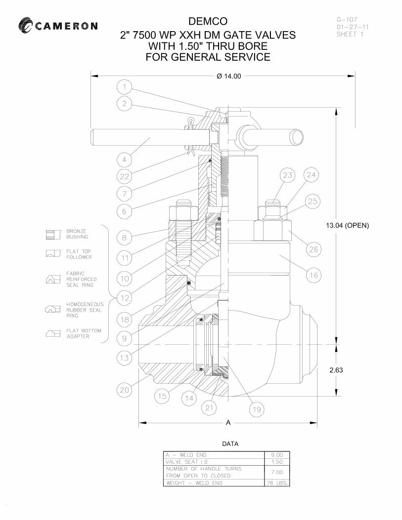
SERIES DM GATE VALVE MAINTENANCE INSTRUCTIONS 2000-3000-5000 2" FULL PORT & 2-1/2" REGULAR PORT
DISASSEMBLY 1. Fully open the gate valve. Unscrew coupling (15) and
withdraw the bonnet assembly from the body. Collapse the seat (21) by compressing the top pins together and remove it from the body.
2. With the bonnet assembly on its side, remove pin (22)
and lock handle (4) then lift off hub (2). Remove coupling (15). Turn stem screw (6) clockwise to bottom, then withdraw gate (19) from stem (9) by rotating a quarter turn and sliding it off the tee-head of the stem.
3. Seat or gate replacement may be made at this point.
To reassemble the valve, proceed from reassembly instruction 3 after following the applicable maintenance instructions. If it is desired to inspect other parts, the following instructions apply.
4. Turn the stem clockwise until it disengages from stem
screw (6) and withdraw it from the underside of the bonnet. Unscrew the lock screw (13) and lift screw housing (8) off the bonnet. Remove retainer (11), o-ring seal (10) and stem seal assembly (12) from the bonnet. Turn stem screw (6) clockwise out of the screw housing. Remove screw seal (7) from the screw housing and bonnet seal (18) from the valve body.
MAINTENANCE Thoroughly clean all parts and inspect them for wear or damage. It is recommended that seals (7), (10), (18) and stem seal assembly (12) be replaced if they are worn or cut. All sealing surfaces should be clean and free of dirt, rust, nicks and scratches. These will include the areas inside the body adjacent to the line bore where the seat fits, the area around the lower part of the bonnet that lies against the bonnet o-ring seal, the bonnet stuffing box and the surface of the stem that passes through the packing. Clean these surfaces well and polish with emery cloth if necessary, paying particular attention to the valve stem. Before reassembling, apply a good grade of general purpose grease to all threads, seal rings and exterior of the seat and on the surfaces of the bonnet, stem and stem screw which are in contact with seals. REASSEMBLY 1. Slide the threaded end of the stem through the bonnet
bore from the underside and place the stem seal assembly over the stem. This assembly consists of a flat bottomed adapter ring, homogeneous rubber seal ring, fabric reinforced seal ring, a flat topped follower ring and a bushing, which are placed over the end of the stem in that order. The lips on "V" rings point towards bottom of bonnet. Slide the retainer (11) with o-ring seal (10) inside over the stem. Seat the stem seal assembly into its counterbore in the bonnet.
2. Engage the stem screw (6) in the screw housing (8)
about half its total travel and place the screw housing on the bonnet and stem. Replace lock screw (13). Place the coupling on the screw housing.
3. Rotate the stem screw clockwise until it bottoms on
the retainer, then back it up approximately one-eighth turn. Engage the gate on the tee-head of the stem and turn them together counterclockwise until the gate touches the underside of the bonnet lugs. Align the gate with the opening between the lugs and retract it into the bonnet by turning the stem screw counterclockwise. Place the hub on the stem screw, insert the lock handle and retain it with the cotter pin. Do not spread the pin since it may be removed later while adjusting the gate level.
4. Install the seat on the bonnet and stand the assembly
upright resting on the seat. Turn the handle clockwise until the hub is stopped by the top of the screw housing.

G-5 SHEET 2 Make a pencil mark on one side of the gate even with the bottom of the seat port. Raise the bottom of the gate into the seat bore by rotating the handle and measure the distance from the pencil mark to the bottom of the gate. This distance must be between 5/16" - 7/16". If the distance is correct, proceed to assembly step 5. If not, remove the seat, lock handle and hub from the assembly. Rotate the stem screw clockwise to bottom then back off one-eighth turn. Turn the gate and stem together while holding the stem screw: counterclockwise to reduce the distance or clockwise to increase the distance as required. One-half turn of the gate and stem changes the distance approximately 1/16". Repeat step 4 until the closed gate position is correct. 5. Replace bonnet seal (18). Assemble seat (21) and
bonnet to the valve body keeping the seat ports aligned with the body line bore, making sure the gate is in the slot in the seat and that the top pins of the seat are in the drilled holes in the bonnet while performing this operation. Tighten the coupling. Spread the cotter pin (22) in the lock handle and repack the hub with general-purpose grease through fitting (1). This is most effectively done when the valve is closed.
TROUBLE SHOOTING DIFFICULTY OF OPERATION may be due to the following: a) Sand or other foreign material packed in the bonnet.
Remove bonnet and clean out. b) Dry threads. Lubricate through the lube fitting. This
is most effectively done when the valve is closed. c) Stem threads galled. Replace stem and/or stem
screw. LEAKAGE THROUGH THE VALVE may be due to the following: a) Washed out gate or seat. Replace damaged parts. b) Improper closed gate position. Set gate as instructed above in the reassembly instructions. LEAKAGE AROUND THE STEM is caused by a damaged stem seal assembly or stem. Replace stem seal assembly and inspect stem for wear. LEAKAGE BETWEEN BODY AND BONNET is caused by a damaged bonnet seal which must be replaced.

G-5A 3-9-01
SHEET 1
SERIES DM GATE VALVE MAINTENANCE INSTRUCTIONS 2000-3000 WP 2-1/2", 3", 4" FULL PORT - 4", 5" REGULAR PORT
5000 WP - 3" FULL PORT, 4" REGULAR PORT CLASS 1500 - 4" FULL PORT
DISASSEMBLY 1. Fully open the gate valve. Remove nuts (26) and
withdraw the bonnet assembly from the body. Collapse the seat (21) by compressing the top pins together and remove it from the body.
2. With the bonnet assembly on its side, remove pin
(22) and lock handle (4) then lift off hub (2). Turn stem screw (6) clockwise to bottom, then withdraw gate (19) from stem (9) by rotating a quarter turn and sliding it off the tee-head of the stem.
3. Seat or gate replacement may be made at this point.
To reassemble the valve, proceed from reassembly instruction 3 after following the applicable maintenance instructions. If it is desired to inspect other parts, the following instructions apply.
4. Turn the stem clockwise until it disengages from
stem screw (6) and withdraw it from the underside of the bonnet. Unscrew the two nuts (24) and lift screw housing (8) off the bonnet. Remove retainer (11), o-ring seal (10) and stem seal assembly (12) from the bonnet. Turn stem screw (6) clockwise out of the screw housing. Remove screw seal (7) from the screw housing and bonnet seal (18) from the valve body.
MAINTENANCE Thoroughly clean all parts and inspect them for wear or damage. It is recommended that seals (7), (10), (18) and stem seal assembly (12) be replaced if they are worn or cut. All sealing surfaces should be clean and free of dirt, rust, nicks and scratches. These will include the areas inside the body adjacent to the line bore where the seat fits, the area around the lower part of the bonnet that lies against the bonnet o-ring seal, the bonnet stuffing box and the surface of the stem that passes through the packing. Clean these surfaces well and polish with emery cloth if necessary, paying particular attention to the valve stem. Before reassembling, apply a good grade of general purpose grease to all threads, seal rings and exterior of the seat and on the surfaces of the bonnet, stem and stem screw which are in contact with seals. REASSEMBLY 1. Slide the threaded end of the stem through the
bonnet bore from the underside and place the stem seal assembly over the stem. This assembly consists of a flat bottomed adapter ring, homogeneous rubber seal ring, fabric reinforced seal ring, a flat-topped follower ring and a bushing, which are placed over the end of the stem in that order. The lips on "V" rings point towards bottom of bonnet. Slide the retainer (11) with o-ring seal (10) inside over the stem. Seat the stem seal assembly into its counterbore in the bonnet.
2. Engage the stem screw (6) in the screw housing (8)
about half its total travel and place the screw housing on the bonnet and stem. Replace nuts (24).
3. Rotate the stem screw clockwise until it bottoms on
the retainer, then back it up approximately one-eighth turn. Engage the gate on the tee-head of the stem and turn them together counterclockwise until the gate touches the underside of the bonnet lugs. Align the gate with the opening between the lugs and retract it into the bonnet by turning the stem screw counterclockwise. Place the hub on the stem screw, insert the lock handle and retain it with the cotter pin. Do not spread the pin since it may be removed later while adjusting the gate level.
4. Install the seat on the bonnet and stand the assembly
upright resting on the seat. Turn the handle clockwise until the hub is stopped by the top of the screw housing.

G-5A SHEET 2 Make a pencil mark on one side of the gate even with the bottom of the seat port. Raise the bottom of the gate into the seat bore by rotating the handle and measure the distance from the pencil mark to the bottom of the gate. This distance must be within the following limits for each size valve:2-1/2" and 3" full port and 4" regular port - 3/8" to 1/2"; 4" full port and 5" regular port - 7/16" to 9/16". If the distance is correct, proceed to assembly step 5. If not, remove the seat, lock handle and hub from the assembly. Rotate the stem screw clockwise to bottom then back off one-eighth turn. Turn the gate and stem together while holding the stem screw: counterclockwise to reduce the distance or clockwise to increase the distance as required. One-half turn of the gate and stem changes the distance approximately 1/16". Repeat step 4 until the closed gate position is correct. 5. Replace bonnet seal (18). Assemble seat (21) and
bonnet to the valve body keeping the seat ports aligned with the body line bore, making sure the gate is in the slot in the seat and that the top pins of the seat are in the drilled holes in the bonnet while performing this operation. Replace and tighten nuts (26). Spread the cotter pin (22) in the lock handle and repack the hub with general-purpose grease through fitting (1).This is most effectively done when the valve is closed.
TROUBLE SHOOTING DIFFICULTY OF OPERATION may be due to the following: a) Sand or other foreign material packed in the
bonnet. Remove bonnet and clean out. b) Dry threads. Lubricate through the lube fitting.
This is most effectively done when the valve is closed
c) Stem threads galled. Replace stem and/or stem screw.
LEAKAGE THROUGH THE VALVE may be due to the following: a) Washed out gate or seat. Replace damaged parts. b) Improper closed gate position. Set gate as instructed above in the reassembly instructions. LEAKAGE AROUND THE STEM is caused by a damaged stem seal assembly or stem. Replace stem seal assembly and inspect stem for wear. LEAKAGE BETWEEN BODY AND BONNET is caused by a damaged bonnet seal which must be replaced.
G-6 3-9-01
SHEET 1
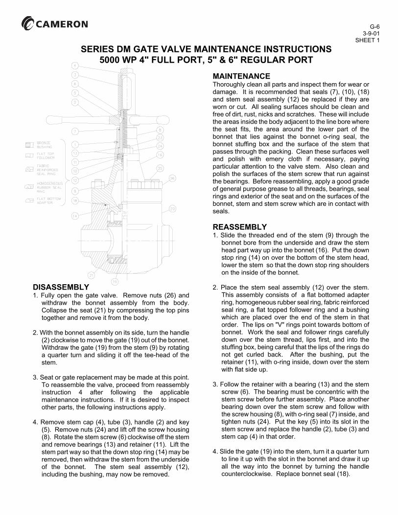
SERIES DM GATE VALVE MAINTENANCE INSTRUCTIONS 5000 WP 4" FULL PORT, 5" & 6" REGULAR PORT
DISASSEMBLY 1. Fully open the gate valve. Remove nuts (26) and
withdraw the bonnet assembly from the body. Collapse the seat (21) by compressing the top pins together and remove it from the body.
2. With the bonnet assembly on its side, turn the handle
(2) clockwise to move the gate (19) out of the bonnet. Withdraw the gate (19) from the stem (9) by rotating a quarter turn and sliding it off the tee-head of the stem.
3. Seat or gate replacement may be made at this point.
To reassemble the valve, proceed from reassembly instruction 4 after following the applicable maintenance instructions. If it is desired to inspect other parts, the following instructions apply.
4. Remove stem cap (4), tube (3), handle (2) and key
(5). Remove nuts (24) and lift off the screw housing (8). Rotate the stem screw (6) clockwise off the stem and remove bearings (13) and retainer (11). Lift the stem part way so that the down stop ring (14) may be removed, then withdraw the stem from the underside of the bonnet. The stem seal assembly (12), including the bushing, may now be removed.
MAINTENANCE Thoroughly clean all parts and inspect them for wear or damage. It is recommended that seals (7), (10), (18) and stem seal assembly (12) be replaced if they are worn or cut. All sealing surfaces should be clean and free of dirt, rust, nicks and scratches. These will include the areas inside the body adjacent to the line bore where the seat fits, the area around the lower part of the bonnet that lies against the bonnet o-ring seal, the bonnet stuffing box and the surface of the stem that passes through the packing. Clean these surfaces well and polish with emery cloth if necessary, paying particular attention to the valve stem. Also clean and polish the surfaces of the stem screw that run against the bearings. Before reassembling, apply a good grade of general purpose grease to all threads, bearings, seal rings and exterior of the seat and on the surfaces of the bonnet, stem and stem screw which are in contact with seals. REASSEMBLY 1. Slide the threaded end of the stem (9) through the
bonnet bore from the underside and draw the stem head part way up into the bonnet (16). Put the down stop ring (14) on over the bottom of the stem head, lower the stem so that the down stop ring shoulders on the inside of the bonnet.
2. Place the stem seal assembly (12) over the stem.
This assembly consists of a flat bottomed adapter ring, homogeneous rubber seal ring, fabric reinforced seal ring, a flat topped follower ring and a bushing which are placed over the end of the stem in that order. The lips on "V" rings point towards bottom of bonnet. Work the seal and follower rings carefully down over the stem thread, lips first, and into the stuffing box, being careful that the lips of the rings do not get curled back. After the bushing, put the retainer (11), with o-ring inside, down over the stem with flat side up.
3. Follow the retainer with a bearing (13) and the stem
screw (6). The bearing must be concentric with the stem screw before further assembly. Place another bearing down over the stem screw and follow with the screw housing (8), with o-ring seal (7) inside, and tighten nuts (24). Put the key (5) into its slot in the stem screw and replace the handle (2), tube (3) and stem cap (4) in that order.
4. Slide the gate (19) into the stem, turn it a quarter turn
to line it up with the slot in the bonnet and draw it up all the way into the bonnet by turning the handle counterclockwise. Replace bonnet seal (18).

G-6 SHEET 2
Assemble seat (21) and bonnet to the valve body keeping the seat ports aligned with the body line bore, making sure the gate is in the slot in the seat and that the top pins on the seat are in the drilled holes in the bonnet while performing this operation. Tighten nuts (26) and repack the screw housing (8) with general-purpose grease through fitting (1).
TROUBLE SHOOTING DIFFICULTY OF OPERATION may be due to the following: a) Sand or other foreign material packed in the bonnet.
Remove bonnet and clean out. b) Dry stem threads. Lubricate through the lube fitting. c) Stem threads galled. Replace stem and/or stem
screw. d) Bearings worn out. Replace LEAKAGE THROUGH THE VALVE may be due to a washed out gate or seat. Replace. LEAKAGE AROUND THE STEM is caused by a damaged stem seal assembly or stem. Replace stem seal assembly and inspect stem for wear. LEAKAGE BETWEEN BODY AND BONNET is caused by a damaged bonnet seal which must be replaced.


![Demco BFV Catalog[1]](https://static.fdocuments.in/doc/165x107/577cd58d1a28ab9e789b1546/demco-bfv-catalog1.jpg)