Demand Response: Passive Proximity Electric Sensing
17
Demand Response Enabling Technologies Development Workshop, June 10, 2004 . Demand Response: Passive Proximity Electric Sensing EECS Department and the Berkeley Sensor & Actuator Center (BSAC) Technology to enable California households to modify their energy use during periods of peak demand / short supply system elements include inexpensive wireless revenue metering, plus electricity use (“sub-metering”) and temperature / humidity monitoring and control inside houses based on knowledge of present and short-range future weather conditions and electric power prices respond automatically to time- and location-dependent price and contingency signals to reduce / shift loads Use of self-organizing wireless sensor platforms is key
Transcript of Demand Response: Passive Proximity Electric Sensing

Demand Response Enabling Technologies Development Workshop, June 10, 2004 .
Demand Response: Passive ProximityElectric Sensing
EECS Department and the Berkeley Sensor & Actuator Center (BSAC)
Technology to enable California households to modify their energy use during periods of peak demand / short supply
system elements include inexpensive wireless revenue metering, plus electricity use (“sub-metering”) and temperature / humidity monitoring andcontrol inside houses based on knowledge of present and short-range
future weather conditions and electric power prices respond automatically to time- and location-dependent price and
contingency signals to reduce / shift loads
Use of self-organizing wireless sensor platforms is key

Demand Response Enabling Technologies Development Workshop, June 10, 2004 .
Sensors (White /BSAC )
VoltageSensor
CurrentSensor
0 50 100 1500
0.5
1
Input Voltage (V)
Mea
sure
d V
olta
ge (V
)
0.00
0.02
0.04
0.06
0.08
0.10
0.12
0 5 10 15
Input Current (A)
Mea
sure
d V
olta
ge (V
)
Traditional Current
Sensors
PASSIVE PROXIMITY CURRENT SENSOR
MOTEADC
PASSIVE PROXIMITYCURRENT SENSOR
APPLIANCE ENERGYSCAVENGING
Demand Response: Passive ProximityElectric Sensing
Demand Response Enabling Technologies Development Workshop, June 10, 2004 .
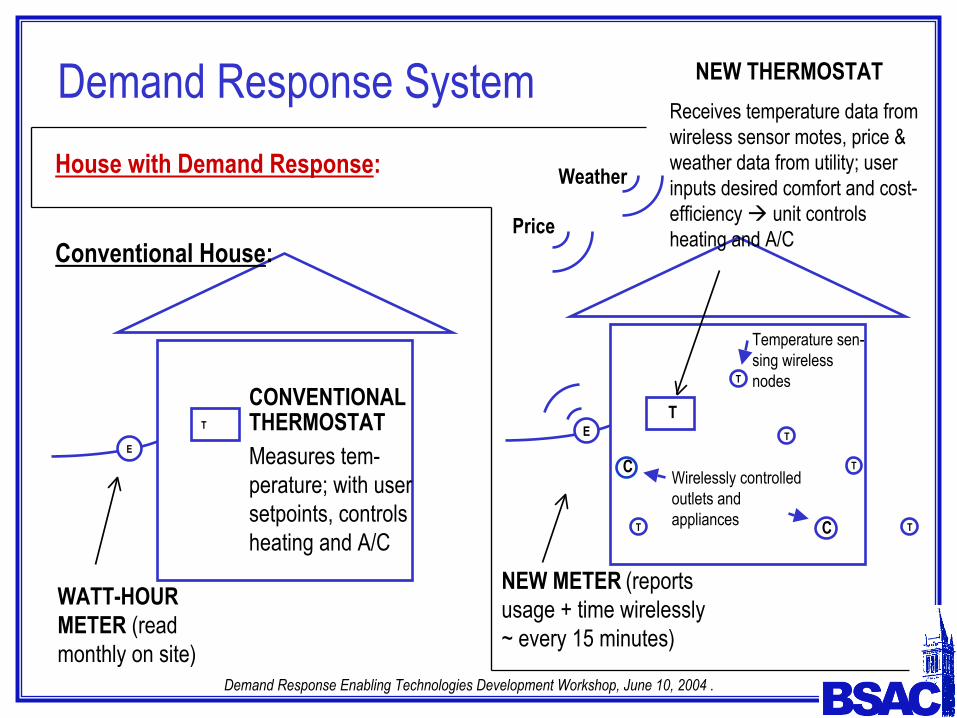
Demand Response System
NEW METER (reportsusage + time wirelessly ~ every 15 minutes)
NEW THERMOSTATReceives temperature data from wireless sensor motes, price & weather data from utility; user inputs desired comfort and cost-efficiency unit controls heating and A/C
E
Price
Weather
T
T
T
T
House with Demand Response:
E
T
Conventional House:
WATT-HOUR METER (read monthly on site)
Measures tem-perature; with user setpoints, controls heating and A/C
CONVENTIONALTHERMOSTAT
Temperature sen-sing wireless nodes
C Wirelessly controlled outlets and appliances
T
T
C

Demand Response Enabling Technologies Development Workshop, June 10, 2004 .
• Elements– AC voltage sensing– AC current sensing– Wireless data transmission
• Goals– Passive (no external power
source required)– Proximity non-conductive
coupling for inexpensive installation
– Low cost (<$50 goal for entire meter)
• Proposed voltage sensor – Uses capacitive coupling
0 50 100 1500
0.5
1
Input Voltage (V)
Mea
sure
d V
olta
ge (V
)
Macro-scale proof-of-concept: Output vs. input of capacitive voltage sensor (two metal sleeves coupled to energized open-circuited “zip” cord). Note linear response.
Power Measurement
Demand Response Enabling Technologies Development Workshop, June 10, 2004 .
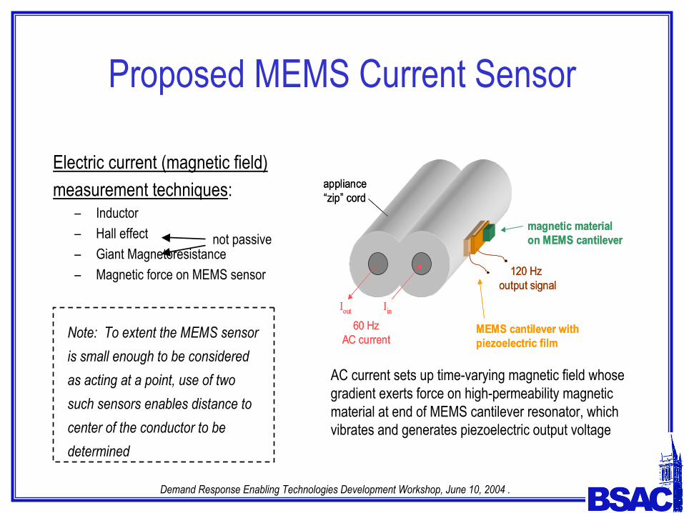
Proposed MEMS Current Sensor
Electric current (magnetic field) measurement techniques:
– Inductor – Hall effect– Giant Magnetoresistance– Magnetic force on MEMS sensor
not passive
Note: To extent the MEMS sensor is small enough to be considered as acting at a point, use of two such sensors enables distance to center of the conductor to be determined
AC current sets up time-varying magnetic field whose gradient exerts force on high-permeability magnetic material at end of MEMS cantilever resonator, which vibrates and generates piezoelectric output voltage
magnetic material on MEMS cantilever
MEMS cantilever with piezoelectric film
Iout Iin
60 Hz AC current
120 Hz output signal
appliance “zip” cord
magnetic material on MEMS cantilever
MEMS cantilever with piezoelectric film
Iout Iin
60 Hz AC current
120 Hz output signal
appliance “zip” cord
Demand Response Enabling Technologies Development Workshop, June 10, 2004 .
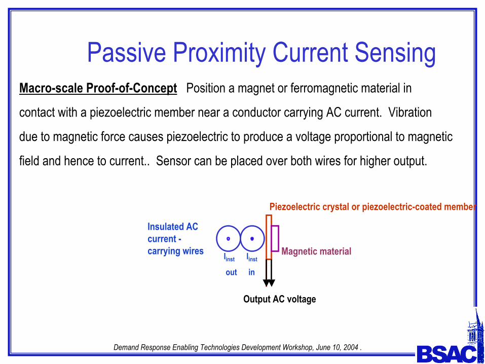
Passive Proximity Current SensingMacro-scale Proof-of-Concept Position a magnet or ferromagnetic material in
contact with a piezoelectric member near a conductor carrying AC current. Vibration
due to magnetic force causes piezoelectric to produce a voltage proportional to magnetic
field and hence to current.. Sensor can be placed over both wires for higher output.
Insulated AC current -carrying wires
Piezoelectric crystal or piezoelectric-coated member
Magnetic material
Output AC voltage
Iinst
out
Iinst
in

Demand Response Enabling Technologies Development Workshop, June 10, 2004 .
Passive Proximity Current Sensing –Data
0.00
0.02
0.04
0.06
0.08
0.10
0.12
0 5 10 15
Input Current (A)
Mea
sure
d V
olta
ge (V
)

Demand Response Enabling Technologies Development Workshop, June 10, 2004 .
Passive Proximity Voltage andCurrent Sensing
Demand Response Enabling Technologies Development Workshop, June 10, 2004 .
BSAC Demand-Response Demos1. Macro proof-of-concept – passive proximity AC voltage sensor
2. Macro proof-of-concept – passive proximity AC current sensor
3. Simulated sensor output handling by Smart Dust mote
4. Wireless transmission of sensor data to Smart Dust base station
5. RMS calculations in Smart Dust mote
6. AC-powered Smart Dust mote, Smart Dust controlled power outlet
7. Macro proof-of-concept clip-on wireless current sensing
8. (Coming) Calculation of power consumption carried out on a Smart Dust mote
Demand Response Enabling Technologies Development Workshop, June 10, 2004 .
Sensor Output Handling by MoteA Smart Dust mote is input voltages representing AC voltage and current waveforms from
those respective sensors. The waveforms are sampled and digitized by the A/D
converter on the mote under control of the Atmel microcontroller.
It has been shown that one can sample one period of the voltage or current waveforms to obtain
data for determining rms values and phases for power computations
After wireless transmission to the base station (connected presently to a laptop computer),
the waveforms can be re-constituted for display and analysis.
In the future, with Smart Dust motes we will do these calculations on the mote and transmit
only the results wirelessly.
Demand Response Enabling Technologies Development Workshop, June 10, 2004 .
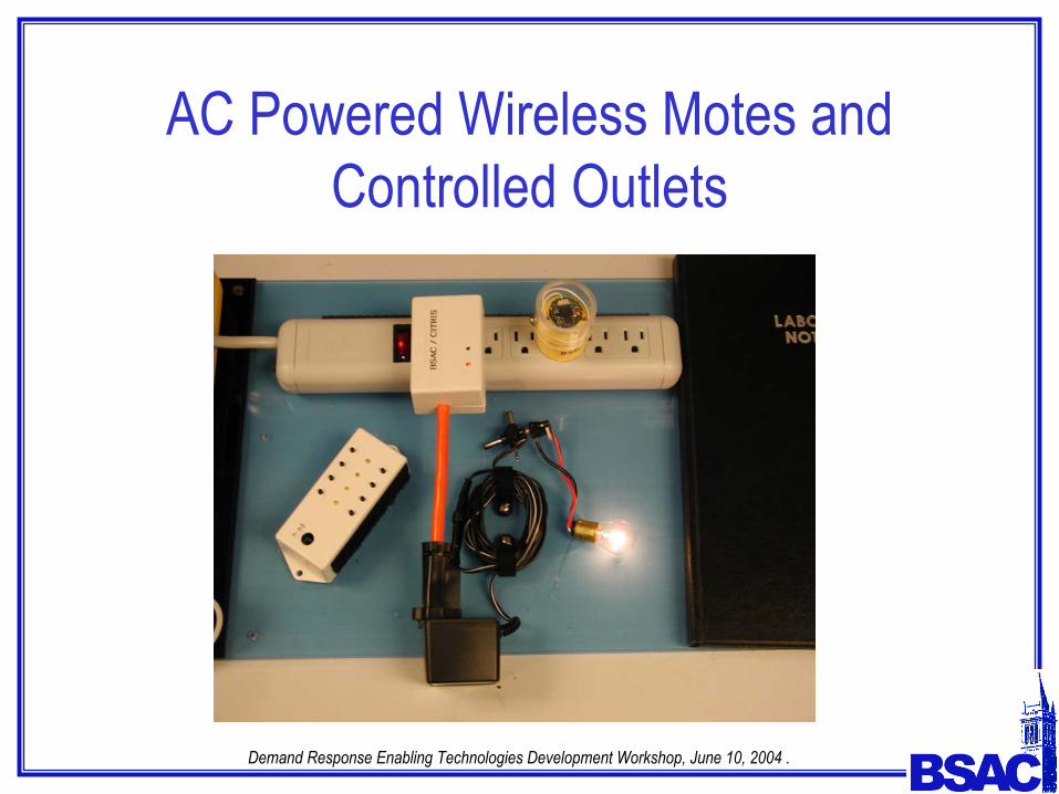
AC Powered Wireless Motes andControlled Outlets
Demand Response Enabling Technologies Development Workshop, June 10, 2004 .
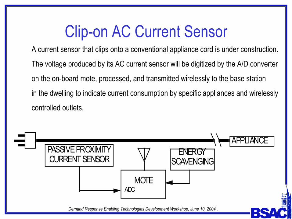
PASSIVE PROXIMITY CURRENT SENSOR
MOTEADC
PASSIVE PROXIMITYCURRENT SENSOR
APPLIANCE ENERGYSCAVENGING
Clip-on AC Current SensorA current sensor that clips onto a conventional appliance cord is under construction.
The voltage produced by its AC current sensor will be digitized by the A/D converter
on the on-board mote, processed, and transmitted wirelessly to the base station
in the dwelling to indicate current consumption by specific appliances and wirelessly
controlled outlets.

Demand Response Enabling Technologies Development Workshop, June 10, 2004 .
Metered Wireless Controlled Outlet
MOTEPOWER
IC
PROXIMITY CURRENTSENSOR
I
VVOLTAGECONDITIONER
AD/DCCONVERTER

Demand Response Enabling Technologies Development Workshop, June 10, 2004 .
Metered Outlet with Hall Effect CurrentSensor
MOTEPOWER
ICI
VVOLTAGECONDITIONER
AD/DCCONVERTER
HALL EFFECTCURRENT SENSOR

Demand Response Enabling Technologies Development Workshop, June 10, 2004 .
Guides for the BSAC Electric SensorDemos
Xin Yang
Jonathan Foster

Demand Response Enabling Technologies Development Workshop, June 10, 2004 .
BSAC – People InvolvedStudents:
Jonathan Foster (graduate student researcher, Applied Science and Technology Program)
Justin Black (graduate student researcher, EECS Department)
Xin Yang (undergraduate CS and Math major)
Vikram Gowrish (undergraduate, EECS Department, support from NSF)
Technical staff:
Ferenc Kovac (Manager, EECS Electronics Support Group)
Tho Nguyen (Associate Engineer)
Thomas Oberheim (formerly Research Engineer, EECS Department)
Faculty:
Dick White (BSAC and EECS Department)
Demand Response Enabling Technologies Development Workshop, June 10, 2004 .
Additional Features to be Explored at BSAC
• Use of novel RFID tag and MEMS technology for sensing voltage, current, temperature, etc.
• Use of low-power-drain transmitters or transceivers for wireless sensor network in dwelling
or workplace employing
-- Sensor output conditioning directly at radio frequency for transmission
-- Scavenging power for transmitter operation from proximity to AC power
circuits
• Application of passive proximity AC sensing to determination of switch and circuit breaker
settings, motor excitation, etc.