DELUGE SYSTEM DESIGN GUIDE
14
Jul-21 DELUGE SYSTEM DESIGN GUIDE
Transcript of DELUGE SYSTEM DESIGN GUIDE
Jul-21
DELUGE SYSTEM DESIGN GUIDE
DELUGE SYSTEM DESIGN GUIDE
1
TABLE OF CONTENTS
1. Introduction 2. Definitions 3. Detection Systems
3.1 Wet Pilot 3.2 Dry Pilot 3.3 Electric Detection
4. Releasing Devices 4.1 Pneumatic Actuators 4.2 Solenoid Valves 4.3 Manual Release 4.4 Pilot Line Detectors
5. Types and Uses of Deluge Systems 5.1 Latching Deluge Valves 5.2 Diaphragm Deluge Valve 5.3 Diaphragm Deluge Valve, Remote-Resetting 5.4 Diaphragm Deluge Valve, Pressure Regulation
6. PrePaKTM Cabinet Mounted Systems
DELUGE SYSTEM DESIGN GUIDE
2
1. INTRODUCTION
This Design Guide has been prepared by The Reliable Automatic Sprinkler Co., Inc. to provide a source of information to help users understand and select deluge system components for a wide variety of fire protection applications. It is complemented by other Reliable Automatic Sprinkler Company design guides that provide more specific insight into supplemental equipment necessary to install a complete system. Note that separate design guides have also been prepared for other types of fire protection systems. This guide will provide a comprehensive overview of deluge systems and their operation while introducing the specific equipment necessary to complete the installation. For a detailed description of the specific equipment outlined in this guide, it will be necessary to obtain the appropriate bulletin. Where applicable, bulletin numbers have been included to facilitate a more detailed analysis and description of Reliable valves and components. Note that the information included herein is only a guide. Responsibility for the actual design and installation of any fire sprinkler system rests with the engineer of record, certified layout technician and/or the Authority Having Jurisdiction (AHJ). For additional product information and other resources, please visit www.reliablesprinkler.com. Should you have additional questions about Reliable products, please do not hesitate to contact our Technical Services Department at 800.557.2726 or email us at [email protected].
DELUGE SYSTEM DESIGN GUIDE
3
2. DEFINITIONS The definitions included in this document are as described in National Fire Protection Association (NFPA) standards where applicable. Those definitions are marked with an asterisk. Where no specific definition is available in the standard, Reliable terminology has been used to describe or define a process, product, or device. Approved*- Acceptable to the authority having jurisdiction. Authority Having Jurisdiction (AHJ)*- An organization, office, or individual responsible for enforcing the requirements of a code or standard, or for approving equipment, materials, an installation, or a procedure. Cross-Zone Detection- A detection method requiring the operation of devices on two different circuits before the alarm condition is initiated. Deluge System*- A sprinkler system employing open sprinklers or nozzles that are attached to a piping system that is connected to a water supply through a valve that is opened by the operation of a detection system installed in the same areas as the sprinklers or the nozzles. When this valve opens, water flows into the piping system and discharges from all sprinklers or nozzles attached thereto. Detector (Electrical)- A device suitable for connection to a circuit that has a sensor that responds to a physical stimulus such as gas, heat, or smoke. Foam-Water Deluge System- A system that discharges a foam-water solution through open fixed spray nozzles or sprinklers. They are commonly used for high challenge fires such as flammable liquids and aircraft hangars. Listed*- Equipment, materials or services included in a list published by an organization that is acceptable to the authority having jurisdiction. Pilot Line Detector*- A standard spray sprinkler or thermostatic fixed-temperature release device used as a detector to release the main valve pneumatically or hydraulically, controlling the flow of water into a fire protection system. Pneumatic Source- An air compressor, nitrogen generator, or some other means to supply supervised air to the sprinkler piping network or dry pilot line. A Pneumatic Source Design Guide is available on the Reliable website. Solenoid Valve- An electrically operated valve wired into a releasing panel and opened with the operation of the electric detection system. Supervised Air Supply- A piping network in a sprinkler system where the air pressure in the system is monitored for an increase or loss of pressure by a high/low air pressure switch. This switch sends a supervisory alarm when pressure drops below or rises above a preset pressure. System control Valve- The valve used to manually turn the incoming water supply on or off. Water control Valve- The valve used to control the release of water into the system. In most preaction or deluge systems this is accomplished with a deluge valve.
DELUGE SYSTEM DESIGN GUIDE
4
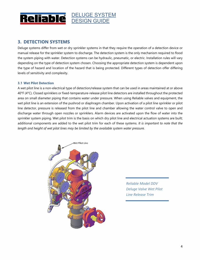
Reliable Model DDV Deluge Valve Wet Pilot Line Release Trim
3. DETECTION SYSTEMS Deluge systems differ from wet or dry sprinkler systems in that they require the operation of a detection device or manual release for the sprinkler system to discharge. The detection system is the only mechanism required to flood the system piping with water. Detection systems can be hydraulic, pneumatic, or electric. Installation rules will vary depending on the type of detection system chosen. Choosing the appropriate detection system is dependent upon the type of hazard and location of the hazard that is being protected. Different types of detection offer differing levels of sensitivity and complexity.
3.1 Wet Pilot Detection A wet pilot line is a non-electrical type of detection/release system that can be used in areas maintained at or above 40°F (4°C). Closed sprinklers or fixed-temperature-release pilot line detectors are installed throughout the protected area on small diameter piping that contains water under pressure. When using Reliable valves and equipment, the wet pilot line is an extension of the pushrod or diaphragm chamber. Upon activation of a pilot line sprinkler or pilot line detector, pressure is released from the pilot line and chamber allowing the water control valve to open and discharge water through open nozzles or sprinklers. Alarm devices are activated upon the flow of water into the sprinkler system piping. Wet pilot trim is the basis on which dry pilot line and electrical actuation systems are built; additional components are added to the wet pilot trim for each of these systems. It is important to note that the length and height of wet pilot lines may be limited by the available system water pressure.

DELUGE SYSTEM DESIGN GUIDE
5
Reliable Model DDV Deluge Valve Dry Pilot Line Release Trim
3.2 Dry Pilot Detection Where freezing conditions exist, or where height/distance limits of wet pilot lines are exceeded, a dry pilot line can be used. Closed sprinklers or fixed-temperature-release pilot line detectors are installed throughout the protected area on small diameter piping that contains pressurized air or nitrogen. A Dry Pilot Actuator is installed on the outlet of the deluge valve pushrod or diaphragm chamber, this device provides a separation between the hydraulically pressurized chamber and the pneumatically pressurized pilot line. The dry pilot line is a pneumatic extension of the pressurized side chamber piping. Upon activation of a pilot line sprinkler or pilot line detector, pneumatic pressure is released from the piping allowing the dry pilot actuator to vent and release hydraulic pressure from the chamber. Alarm devices are activated upon the flow of water into the sprinkler system piping. Pneumatic pressure in the dry pilot line can be provided from several sources and must be maintained by a listed pressure maintenance device. Pneumatic sources include tank-mounted compressors, plant air systems, nitrogen generators, or nitrogen cylinders. To prevent accidental system activation, pneumatic pressure is monitored by a pressure switch that will initiate a signal in the event of low pressure due to damage to the pipe or release device, or failure of the compressed gas system.
DELUGE SYSTEM DESIGN GUIDE
6
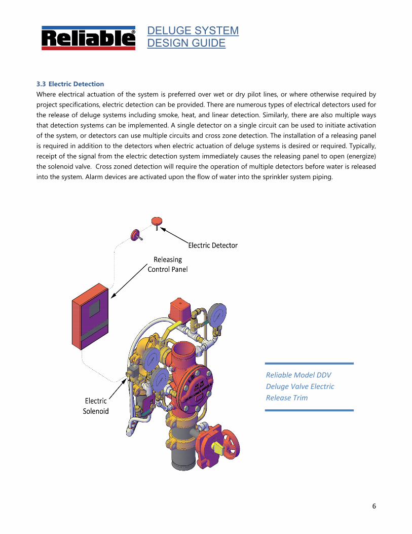
Reliable Model DDV Deluge Valve Electric Release Trim
3.3 Electric Detection Where electrical actuation of the system is preferred over wet or dry pilot lines, or where otherwise required by project specifications, electric detection can be provided. There are numerous types of electrical detectors used for the release of deluge systems including smoke, heat, and linear detection. Similarly, there are also multiple ways that detection systems can be implemented. A single detector on a single circuit can be used to initiate activation of the system, or detectors can use multiple circuits and cross zone detection. The installation of a releasing panel is required in addition to the detectors when electric actuation of deluge systems is desired or required. Typically, receipt of the signal from the electric detection system immediately causes the releasing panel to open (energize) the solenoid valve. Cross zoned detection will require the operation of multiple detectors before water is released into the system. Alarm devices are activated upon the flow of water into the sprinkler system piping.
DELUGE SYSTEM DESIGN GUIDE
7
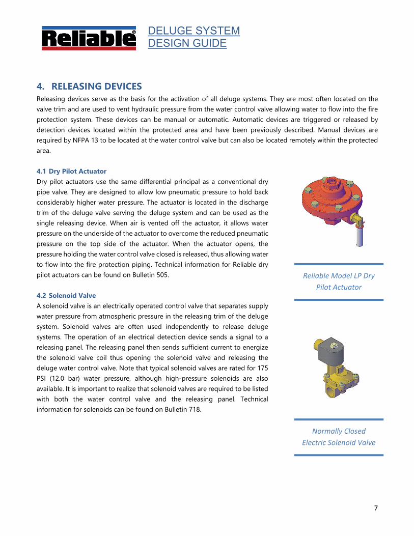
Reliable Model LP Dry Pilot Actuator
Normally Closed Electric Solenoid Valve
4. RELEASING DEVICES Releasing devices serve as the basis for the activation of all deluge systems. They are most often located on the valve trim and are used to vent hydraulic pressure from the water control valve allowing water to flow into the fire protection system. These devices can be manual or automatic. Automatic devices are triggered or released by detection devices located within the protected area and have been previously described. Manual devices are required by NFPA 13 to be located at the water control valve but can also be located remotely within the protected area. 4.1 Dry Pilot Actuator Dry pilot actuators use the same differential principal as a conventional dry pipe valve. They are designed to allow low pneumatic pressure to hold back considerably higher water pressure. The actuator is located in the discharge trim of the deluge valve serving the deluge system and can be used as the single releasing device. When air is vented off the actuator, it allows water pressure on the underside of the actuator to overcome the reduced pneumatic pressure on the top side of the actuator. When the actuator opens, the pressure holding the water control valve closed is released, thus allowing water to flow into the fire protection piping. Technical information for Reliable dry pilot actuators can be found on Bulletin 505. 4.2 Solenoid Valve A solenoid valve is an electrically operated control valve that separates supply water pressure from atmospheric pressure in the releasing trim of the deluge system. Solenoid valves are often used independently to release deluge systems. The operation of an electrical detection device sends a signal to a releasing panel. The releasing panel then sends sufficient current to energize the solenoid valve coil thus opening the solenoid valve and releasing the deluge water control valve. Note that typical solenoid valves are rated for 175 PSI (12.0 bar) water pressure, although high-pressure solenoids are also available. It is important to realize that solenoid valves are required to be listed with both the water control valve and the releasing panel. Technical information for solenoids can be found on Bulletin 718.
DELUGE SYSTEM DESIGN GUIDE
8
Manual Emergency Release
Reliable Model F1-FTR Pilot Line Detector
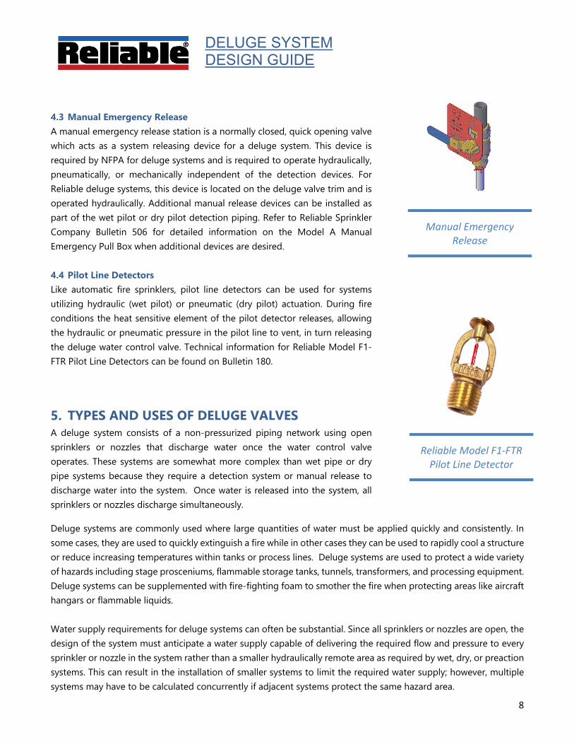
4.3 Manual Emergency Release A manual emergency release station is a normally closed, quick opening valve which acts as a system releasing device for a deluge system. This device is required by NFPA for deluge systems and is required to operate hydraulically, pneumatically, or mechanically independent of the detection devices. For Reliable deluge systems, this device is located on the deluge valve trim and is operated hydraulically. Additional manual release devices can be installed as part of the wet pilot or dry pilot detection piping. Refer to Reliable Sprinkler Company Bulletin 506 for detailed information on the Model A Manual Emergency Pull Box when additional devices are desired. 4.4 Pilot Line Detectors Like automatic fire sprinklers, pilot line detectors can be used for systems utilizing hydraulic (wet pilot) or pneumatic (dry pilot) actuation. During fire conditions the heat sensitive element of the pilot detector releases, allowing the hydraulic or pneumatic pressure in the pilot line to vent, in turn releasing the deluge water control valve. Technical information for Reliable Model F1-FTR Pilot Line Detectors can be found on Bulletin 180.
5. TYPES AND USES OF DELUGE VALVES A deluge system consists of a non-pressurized piping network using open sprinklers or nozzles that discharge water once the water control valve operates. These systems are somewhat more complex than wet pipe or dry pipe systems because they require a detection system or manual release to discharge water into the system. Once water is released into the system, all sprinklers or nozzles discharge simultaneously.
Deluge systems are commonly used where large quantities of water must be applied quickly and consistently. In some cases, they are used to quickly extinguish a fire while in other cases they can be used to rapidly cool a structure or reduce increasing temperatures within tanks or process lines. Deluge systems are used to protect a wide variety of hazards including stage prosceniums, flammable storage tanks, tunnels, transformers, and processing equipment. Deluge systems can be supplemented with fire-fighting foam to smother the fire when protecting areas like aircraft hangars or flammable liquids. Water supply requirements for deluge systems can often be substantial. Since all sprinklers or nozzles are open, the design of the system must anticipate a water supply capable of delivering the required flow and pressure to every sprinkler or nozzle in the system rather than a smaller hydraulically remote area as required by wet, dry, or preaction systems. This can result in the installation of smaller systems to limit the required water supply; however, multiple systems may have to be calculated concurrently if adjacent systems protect the same hazard area.
DELUGE SYSTEM DESIGN GUIDE
9
Model DDX Set Condition
Model DDX in Flowing Condition
Model DDX in Rest Condition
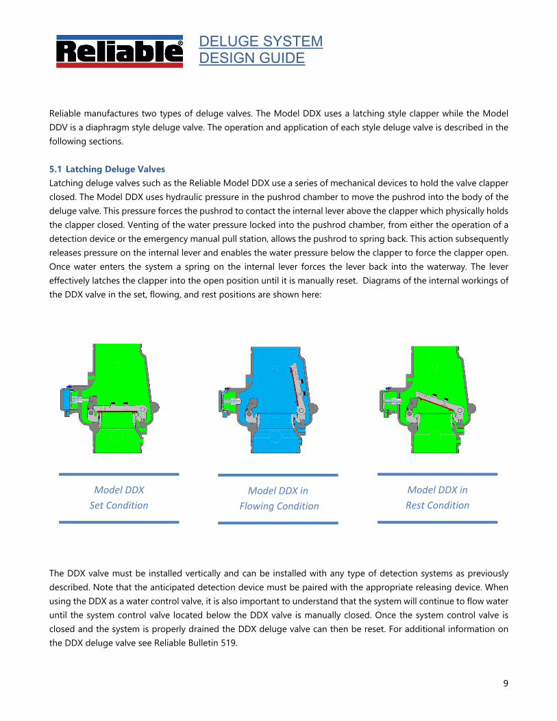
Reliable manufactures two types of deluge valves. The Model DDX uses a latching style clapper while the Model DDV is a diaphragm style deluge valve. The operation and application of each style deluge valve is described in the following sections. 5.1 Latching Deluge Valves Latching deluge valves such as the Reliable Model DDX use a series of mechanical devices to hold the valve clapper closed. The Model DDX uses hydraulic pressure in the pushrod chamber to move the pushrod into the body of the deluge valve. This pressure forces the pushrod to contact the internal lever above the clapper which physically holds the clapper closed. Venting of the water pressure locked into the pushrod chamber, from either the operation of a detection device or the emergency manual pull station, allows the pushrod to spring back. This action subsequently releases pressure on the internal lever and enables the water pressure below the clapper to force the clapper open. Once water enters the system a spring on the internal lever forces the lever back into the waterway. The lever effectively latches the clapper into the open position until it is manually reset. Diagrams of the internal workings of the DDX valve in the set, flowing, and rest positions are shown here:
The DDX valve must be installed vertically and can be installed with any type of detection systems as previously described. Note that the anticipated detection device must be paired with the appropriate releasing device. When using the DDX as a water control valve, it is also important to understand that the system will continue to flow water until the system control valve located below the DDX valve is manually closed. Once the system control valve is closed and the system is properly drained the DDX deluge valve can then be reset. For additional information on the DDX deluge valve see Reliable Bulletin 519.
DELUGE SYSTEM DESIGN GUIDE
10
Model DDV Set Condition
Model DDV Flowing Condition
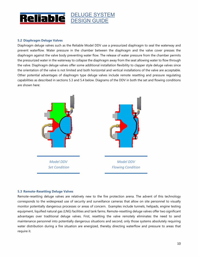
5.2 Diaphragm Deluge Valves Diaphragm deluge valves such as the Reliable Model DDV use a pressurized diaphragm to seal the waterway and prevent waterflow. Water pressure in the chamber between the diaphragm and the valve cover presses the diaphragm against the valve body preventing water flow. The release of water pressure from the chamber permits the pressurized water in the waterway to collapse the diaphragm away from the seat allowing water to flow through the valve. Diaphragm deluge valves offer some additional installation flexibility to clapper style deluge valves since the orientation of the valve is not limited and both horizontal and vertical installations of the valve are acceptable. Other potential advantages of diaphragm type deluge valves include remote resetting and pressure regulating capabilities as described in sections 5.3 and 5.4 below. Diagrams of the DDV in both the set and flowing conditions are shown here:
5.3 Remote-Resetting Deluge Valves Remote-resetting deluge valves are relatively new to the fire protection arena. The advent of this technology corresponds to the widespread use of security and surveillance cameras that allow on site personnel to visually monitor potentially dangerous processes or areas of concern. Examples include tunnels, helipads, engine testing equipment, liquified natural gas (LNG) facilities and tank farms. Remote-resetting deluge valves offer two significant advantages over traditional deluge valves. First, resetting the valve remotely eliminates the need to send maintenance personnel into potentially dangerous situations and second, only those systems absolutely requiring water distribution during a fire situation are energized, thereby directing waterflow and pressure to areas that require it.
DELUGE SYSTEM DESIGN GUIDE
11
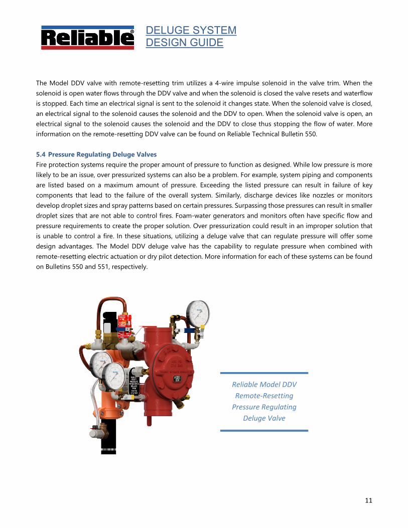
Reliable Model DDV Remote-Resetting
Pressure Regulating Deluge Valve
The Model DDV valve with remote-resetting trim utilizes a 4-wire impulse solenoid in the valve trim. When the solenoid is open water flows through the DDV valve and when the solenoid is closed the valve resets and waterflow is stopped. Each time an electrical signal is sent to the solenoid it changes state. When the solenoid valve is closed, an electrical signal to the solenoid causes the solenoid and the DDV to open. When the solenoid valve is open, an electrical signal to the solenoid causes the solenoid and the DDV to close thus stopping the flow of water. More information on the remote-resetting DDV valve can be found on Reliable Technical Bulletin 550.
5.4 Pressure Regulating Deluge Valves Fire protection systems require the proper amount of pressure to function as designed. While low pressure is more likely to be an issue, over pressurized systems can also be a problem. For example, system piping and components are listed based on a maximum amount of pressure. Exceeding the listed pressure can result in failure of key components that lead to the failure of the overall system. Similarly, discharge devices like nozzles or monitors develop droplet sizes and spray patterns based on certain pressures. Surpassing those pressures can result in smaller droplet sizes that are not able to control fires. Foam-water generators and monitors often have specific flow and pressure requirements to create the proper solution. Over pressurization could result in an improper solution that is unable to control a fire. In these situations, utilizing a deluge valve that can regulate pressure will offer some design advantages. The Model DDV deluge valve has the capability to regulate pressure when combined with remote-resetting electric actuation or dry pilot detection. More information for each of these systems can be found on Bulletins 550 and 551, respectively.
DELUGE SYSTEM DESIGN GUIDE
12
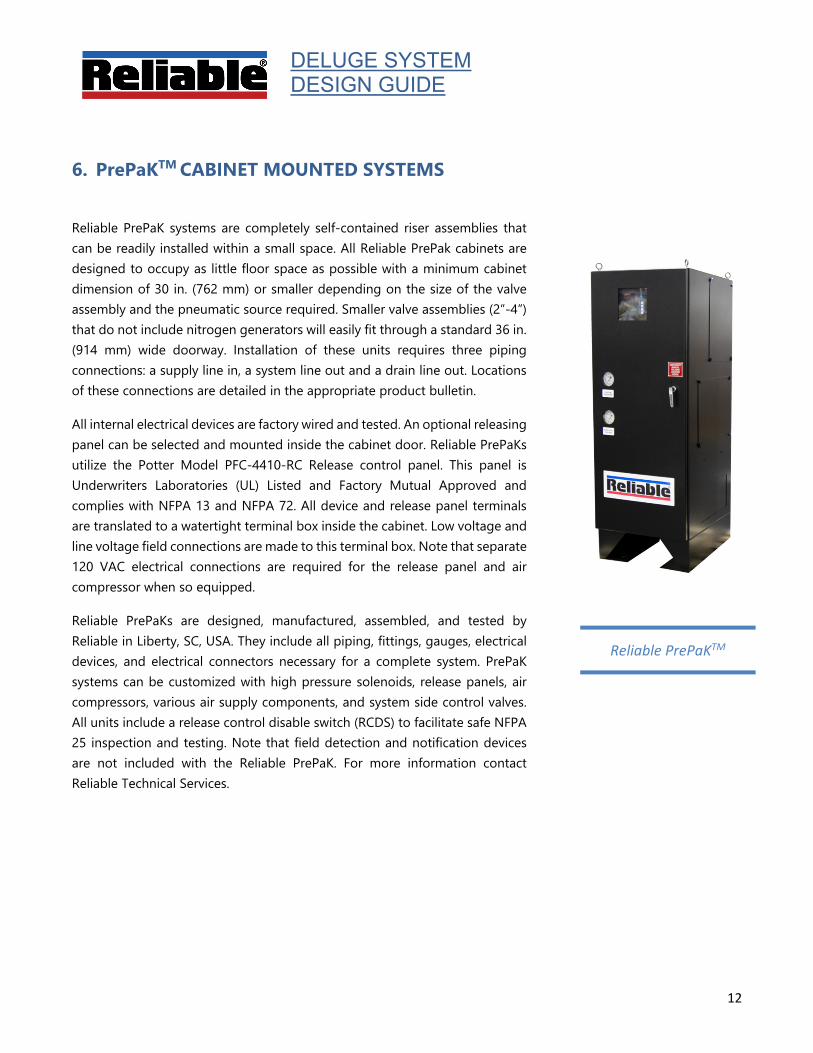
Reliable PrePaKTM
6. PrePaKTM CABINET MOUNTED SYSTEMS
Reliable PrePaK systems are completely self-contained riser assemblies that can be readily installed within a small space. All Reliable PrePak cabinets are designed to occupy as little floor space as possible with a minimum cabinet dimension of 30 in. (762 mm) or smaller depending on the size of the valve assembly and the pneumatic source required. Smaller valve assemblies (2”-4”) that do not include nitrogen generators will easily fit through a standard 36 in. (914 mm) wide doorway. Installation of these units requires three piping connections: a supply line in, a system line out and a drain line out. Locations of these connections are detailed in the appropriate product bulletin.
All internal electrical devices are factory wired and tested. An optional releasing panel can be selected and mounted inside the cabinet door. Reliable PrePaKs utilize the Potter Model PFC-4410-RC Release control panel. This panel is Underwriters Laboratories (UL) Listed and Factory Mutual Approved and complies with NFPA 13 and NFPA 72. All device and release panel terminals are translated to a watertight terminal box inside the cabinet. Low voltage and line voltage field connections are made to this terminal box. Note that separate 120 VAC electrical connections are required for the release panel and air compressor when so equipped.
Reliable PrePaKs are designed, manufactured, assembled, and tested by Reliable in Liberty, SC, USA. They include all piping, fittings, gauges, electrical devices, and electrical connectors necessary for a complete system. PrePaK systems can be customized with high pressure solenoids, release panels, air compressors, various air supply components, and system side control valves. All units include a release control disable switch (RCDS) to facilitate safe NFPA 25 inspection and testing. Note that field detection and notification devices are not included with the Reliable PrePaK. For more information contact Reliable Technical Services.

103 Fairview Park Drive, Elmsford NY 10523
PLEASE CONTACT RELIABLE TECHNICAL SERVICES FOR
ADDITIONAL SUPPORT 800.557.2726
DESIGN GUIDES AVAILABLE FROM