Delta UPS - Modulon Family
88
The power behind competitiveness www.deltapowersolutions.com Delta UPS - Modulon Family NH Plus Series, Three Phase 20-120 kVA User Manual
Transcript of Delta UPS - Modulon Family

The power behind competitiveness
www.deltapowersolutions.com
Delta UPS - Modulon FamilyNH Plus Series, Three Phase20-120 kVA
User Manual
Modulon NH Plus Series
Save This Manual
This manual contains important instructions and warnings that you should follow during the installation, operation, storage and maintenance of this product. Failure to heed these instructions and warnings will void the warranty. Copyright © 2015 by Delta Electronics Inc. All Rights Reserved. All rights of this User Manual (“Manual”), including but not limited to the contents, information, and figures are solely owned and reserved by Delta Electronics Inc. (“Delta”). The Manual can only be applied to the operation or the use of this product. Any disposition, duplication, dissemination, reproduction, modification, translation, extraction, or usage of this Manual in whole or in part is prohibited without the prior written permission of Delta. Given that Delta will continuously improve and develop the product, changes may be made to the information in this Manual at any time without obligation to notify any person of such revision or changes. Delta will make all possible efforts to secure the accuracy and the integrity of this Manual. Delta disclaims any kinds or forms of warranty, guarantee, or undertaking, either expressly or implicitly, including but not limited to the completeness, faultlessness, accuracy, non-infringement, merchantability or fitness for a particular purpose of the Manual.
Contents
Contents
0. Important Safety Instructions.......................................................................... 0-1
1. Introduction ...................................................................................................... 1-1
1-1 Advanced Features ..................................................................................... 1-1
2. Operation .......................................................................................................... 2-1
2-1 Normal Mode (Single Installation) ............................................................... 2-1
2-2 Backup Mode (Single Installation) ............................................................... 2-1
2-3 Bypass Mode (Single Installation) ............................................................... 2-2
2-4 Manual Bypass Mode (Single Installation) .................................................. 2-3
2-5 Normal Mode (Parallel) ............................................................................... 2-4
2-6 Backup Mode (Parallel) ............................................................................... 2-5
2-7 Bypass Mode (Parallel) ............................................................................... 2-6
2-8 Manual Bypass Mode (Parallel)................................................................... 2-7
2-9 Hot Standby Redundancy............................................................................ 2-8
3. General View..................................................................................................... 3-1
3-1 Appearance ................................................................................................. 3-1
3-1-1 Dimension ........................................................................................ 3-2
3-2 Function Introduction................................................................................... 3-3
3-2-1 Front Panel ...................................................................................... 3-3
3-2-2 Rear Panel ....................................................................................... 3-4
3-2-3 External Battery Cabinet – Rear Panel ............................................ 3-5
3-2-4 Power Module .................................................................................. 3-6
3-3 Interface ...................................................................................................... 3-7
3-3-1 Dry Contact Input ............................................................................. 3-8
3-3-2 Dry Contact Output .......................................................................... 3-10
3-3-3 RS232 Port ...................................................................................... 3-12
3-3-4 Parallel Port ..................................................................................... 3-12
3-3-5 Smart Card Slot................................................................................ 3-12
Modulon NH Plus Series
1. SNMP Card................................................................................. 3-13
2. Programmable Relay I/O Card.................................................... 3-14
3. ModBUS Card............................................................................. 3-16
3-4 Other Optional Accessories......................................................................... 3-17
1. Environmental Sensor ................................................................ 3-17
2. SNMP + Switching Hub .............................................................. 3-18
3-5 Technical Specification ................................................................................ 3-19
4. Installation and Wiring ..................................................................................... 4-1
4-1 Before Installation........................................................................................ 4-1
4-2 Package Inspections ................................................................................... 4-1
4-3 Storing Conditions for Delayed Installation.................................................. 4-1
4-4 Installation Environment and Position ......................................................... 4-2
4-4-1 Handling Safety................................................................................ 4-2
4-4-2 UPS Position.................................................................................... 4-2
4-4-3 Installation Environment................................................................... 4-4
4-5 Wiring .......................................................................................................... 4-5
4-5-1 Preparations..................................................................................... 4-5
4-5-2 Wiring (Single Unit) .......................................................................... 4-6
4-5-3 Connecting External Battery Cabinet ............................................... 4-8
4-5-4 Wiring (Parallel Redundancy, Single Input) ...................................... 4-10
4-5-5 Wiring (Parallel Redundancy, Dual Input) ........................................ 4-11
5. Operating Procedures...................................................................................... 5-1
5-1 Startup Procedures (Single Unit) ................................................................. 5-1
5-2 Battery Startup Procedures (Single Unit)..................................................... 5-2
5-3 Shutdown Procedures (Single Unit) ............................................................ 5-2
5-4 Manual Bypass Startup Procedures (Single Unit)........................................ 5-3
5-5 Startup Procedures (Parallel Redundancy) ................................................. 5-4
5-6 Shutdown Procedures (Parallel Redundancy)............................................. 5-4
5-7 Manual Bypass Startup Procedures (Parallel Redundancy) ........................ 5-5
6. Power Module Replacement............................................................................. 6-1 6-1 Status LED Indicators for Power Module..................................................... 6-1
6-2 Power Module Replacement ....................................................................... 6-2
Contents
7. Display and Configuration................................................................................ 7-1 7-1 Control Panel .............................................................................................. 7-1
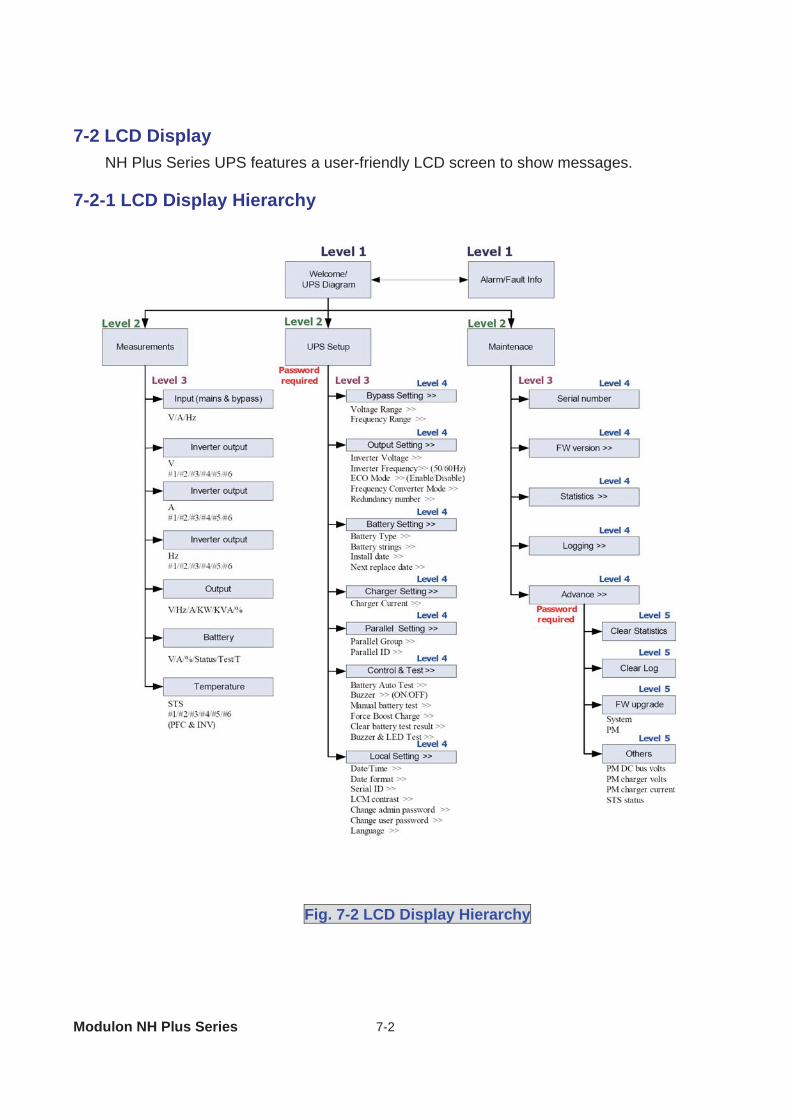
7-2 LCD Display ................................................................................................ 7-2
7-2-1 LCD Display Hierarchy..................................................................... 7-2
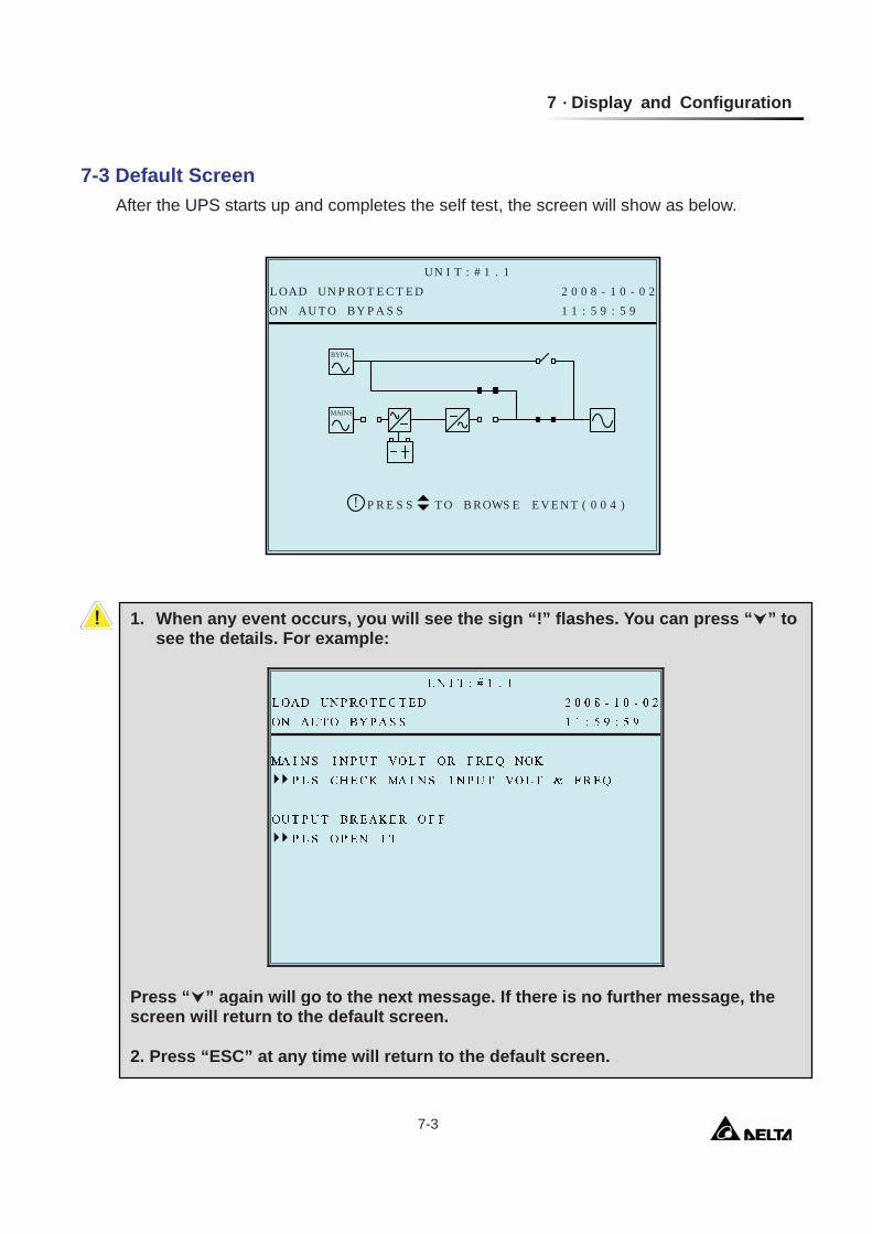
7-3 Default Screen............................................................................................. 7-3
7-3-1 Status Display .................................................................................. 7-4
7-4 Main Menu .................................................................................................. 7-9
7-5 UPS Setup .................................................................................................. 7-11
a. Bypass Setup ........................................................................................ 7-12
b. Output Setup ......................................................................................... 7-13
c. Battery Setup......................................................................................... 7-15
d. Charger Setup ....................................................................................... 7-17
e. Parallel Setup ........................................................................................ 7-18
f. Control & Test Setup............................................................................... 7-19
g. Local Setup ........................................................................................... 7-21
7-6 Maintenance................................................................................................ 7-23
8. Power Management Software .......................................................................... 8-1 8-1 DELTA Software Family............................................................................... 8-1
8-2 UPSentry Smart 2000 ................................................................................. 8-2
8-2-1 Flexible Management Functions of UPSentry Smart 2000............... 8-3
8-3 InsightPower Manager ................................................................................ 8-5
9. Warranty............................................................................................................. 9-1
Modulon NH Plus Series 0-1
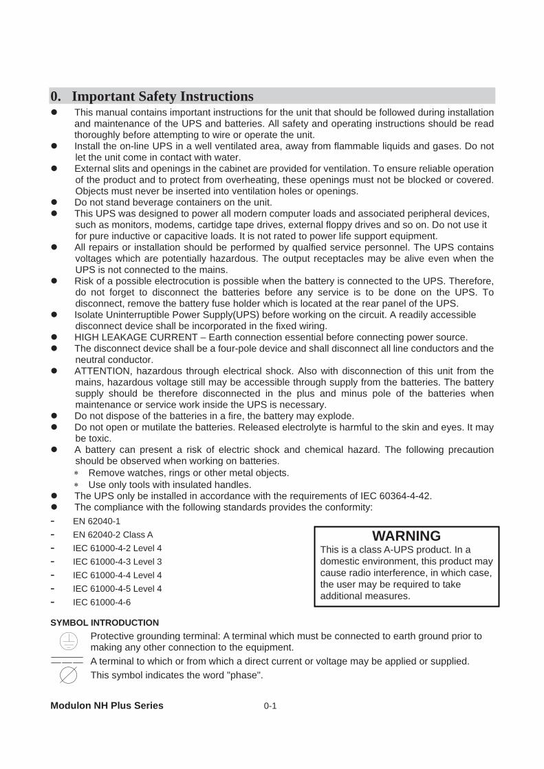
WARNING This is a class A-UPS product. In a domestic environment, this product may cause radio interference, in which case, the user may be required to take additional measures.
0. Important Safety Instructions This manual contains important instructions for the unit that should be followed during installation
and maintenance of the UPS and batteries. All safety and operating instructions should be read thoroughly before attempting to wire or operate the unit.
Install the on-line UPS in a well ventilated area, away from flammable liquids and gases. Do not let the unit come in contact with water.
External slits and openings in the cabinet are provided for ventilation. To ensure reliable operation of the product and to protect from overheating, these openings must not be blocked or covered. Objects must never be inserted into ventilation holes or openings.
Do not stand beverage containers on the unit. This UPS was designed to power all modern computer loads and associated peripheral devices,
such as monitors, modems, cartidge tape drives, external floppy drives and so on. Do not use it for pure inductive or capacitive loads. It is not rated to power life support equipment.
All repairs or installation should be performed by qualfied service personnel. The UPS contains voltages which are potentially hazardous. The output receptacles may be alive even when the UPS is not connected to the mains.
Risk of a possible electrocution is possible when the battery is connected to the UPS. Therefore, do not forget to disconnect the batteries before any service is to be done on the UPS. To disconnect, remove the battery fuse holder which is located at the rear panel of the UPS.
Isolate Uninterruptible Power Supply(UPS) before working on the circuit. A readily accessible disconnect device shall be incorporated in the fixed wiring.
HIGH LEAKAGE CURRENT – Earth connection essential before connecting power source. The disconnect device shall be a four-pole device and shall disconnect all line conductors and the
neutral conductor. ATTENTION, hazardous through electrical shock. Also with disconnection of this unit from the
mains, hazardous voltage still may be accessible through supply from the batteries. The battery supply should be therefore disconnected in the plus and minus pole of the batteries when maintenance or service work inside the UPS is necessary.
Do not dispose of the batteries in a fire, the battery may explode. Do not open or mutilate the batteries. Released electrolyte is harmful to the skin and eyes. It may
be toxic. A battery can present a risk of electric shock and chemical hazard. The following precaution
should be observed when working on batteries. Remove watches, rings or other metal objects. Use only tools with insulated handles.
The UPS only be installed in accordance with the requirements of IEC 60364-4-42. The compliance with the following standards provides the conformity:
- EN 62040-1 - EN 62040-2 Class A - IEC 61000-4-2 Level 4 - IEC 61000-4-3 Level 3 - IEC 61000-4-4 Level 4 - IEC 61000-4-5 Level 4 - IEC 61000-4-6 SYMBOL INTRODUCTION
Protective grounding terminal: A terminal which must be connected to earth ground prior to making any other connection to the equipment. A terminal to which or from which a direct current or voltage may be applied or supplied. This symbol indicates the word "phase".
1 Introduction
1-1
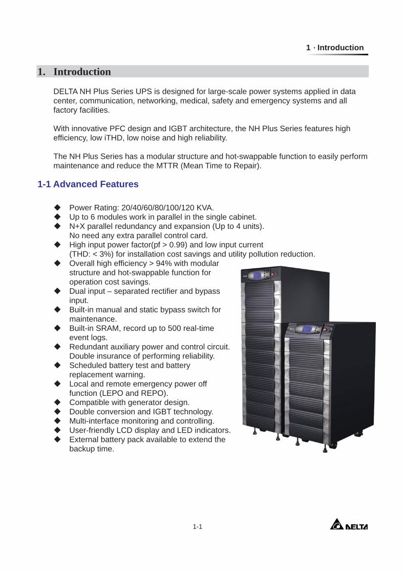
1. Introduction DELTA NH Plus Series UPS is designed for large-scale power systems applied in data center, communication, networking, medical, safety and emergency systems and all factory facilities. With innovative PFC design and IGBT architecture, the NH Plus Series features high efficiency, low iTHD, low noise and high reliability.
The NH Plus Series has a modular structure and hot-swappable function to easily perform maintenance and reduce the MTTR (Mean Time to Repair).
1-1 Advanced Features
Power Rating: 20/40/60/80/100/120 KVA. Up to 6 modules work in parallel in the single cabinet. N+X parallel redundancy and expansion (Up to 4 units).
No need any extra parallel control card. High input power factor(pf > 0.99) and low input current
(THD: < 3%) for installation cost savings and utility pollution reduction. Overall high efficiency > 94% with modular
structure and hot-swappable function for operation cost savings.
Dual input – separated rectifier and bypass input.
Built-in manual and static bypass switch for maintenance.
Built-in SRAM, record up to 500 real-time event logs.
Redundant auxiliary power and control circuit. Double insurance of performing reliability.
Scheduled battery test and battery replacement warning.
Local and remote emergency power off function (LEPO and REPO).
Compatible with generator design. Double conversion and IGBT technology. Multi-interface monitoring and controlling. User-friendly LCD display and LED indicators. External battery pack available to extend the
backup time.
Modulon NH Plus Series 2-1
2. Operation
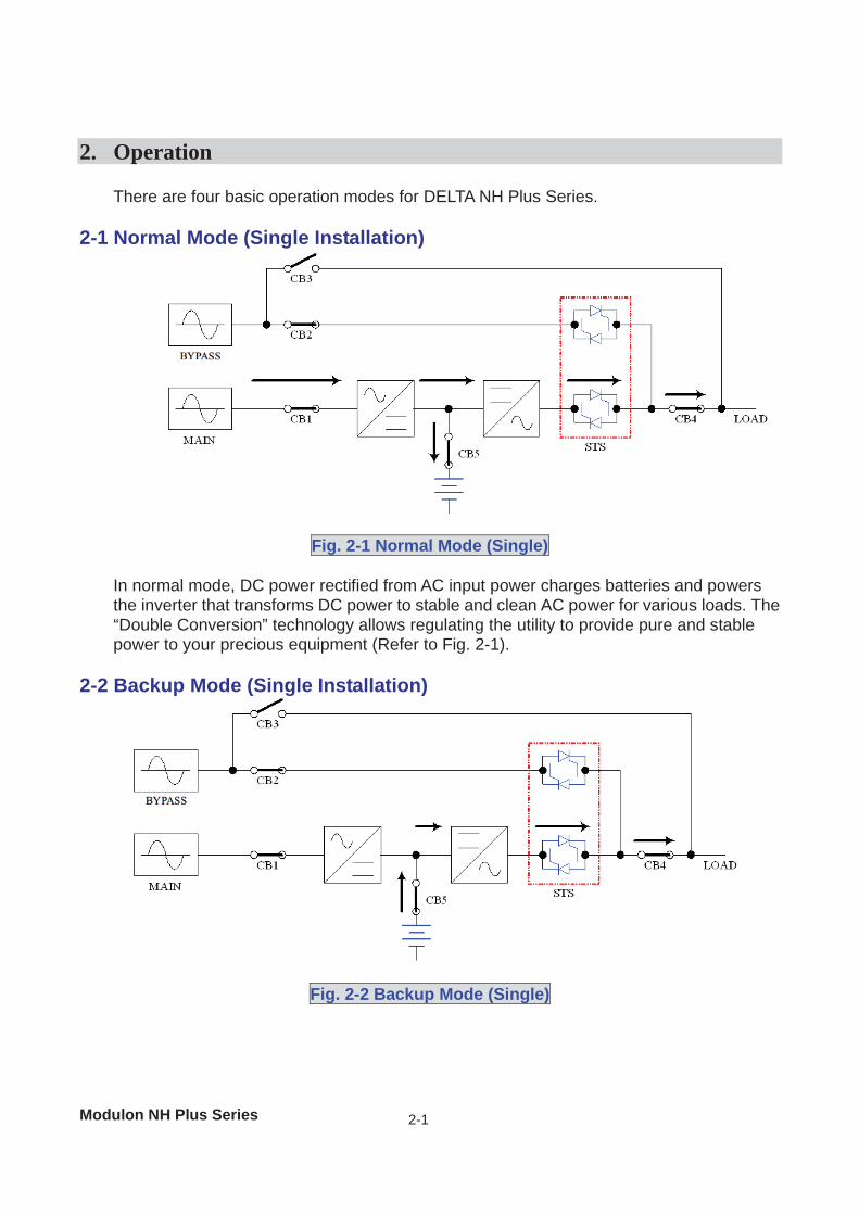
There are four basic operation modes for DELTA NH Plus Series. 2-1 Normal Mode (Single Installation)
Fig. 2-1 Normal Mode (Single) In normal mode, DC power rectified from AC input power charges batteries and powers the inverter that transforms DC power to stable and clean AC power for various loads. The “Double Conversion” technology allows regulating the utility to provide pure and stable power to your precious equipment (Refer to Fig. 2-1).
2-2 Backup Mode (Single Installation)
Fig. 2-2 Backup Mode (Single)
2 Operation
2-2
When a power event (blackout, transient, surge, fluctuation…) occurs, the UPS will automatically transfer from normal mode to backup mode. The battery will provide emergency power to the inverter and then to the loads (Refer to Fig. 2-2).
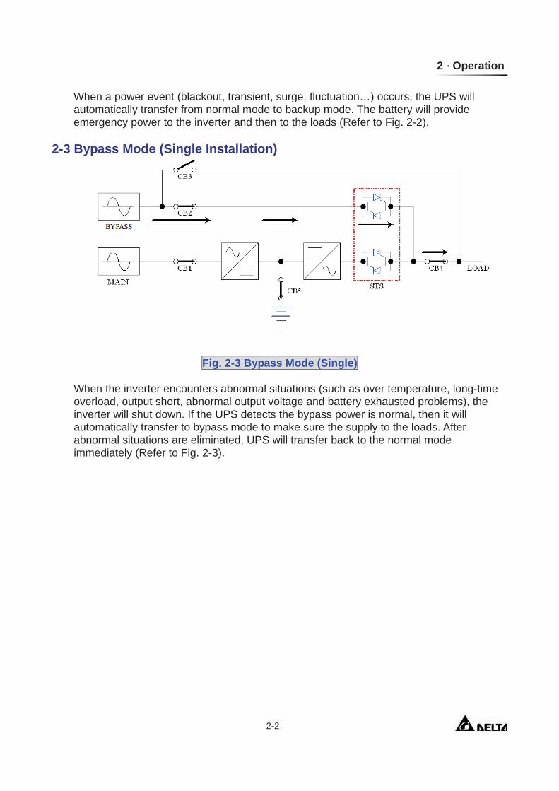
2-3 Bypass Mode (Single Installation)
Fig. 2-3 Bypass Mode (Single)
When the inverter encounters abnormal situations (such as over temperature, long-time overload, output short, abnormal output voltage and battery exhausted problems), the inverter will shut down. If the UPS detects the bypass power is normal, then it will automatically transfer to bypass mode to make sure the supply to the loads. After abnormal situations are eliminated, UPS will transfer back to the normal mode immediately (Refer to Fig. 2-3).
Modulon NH Plus Series 2-3
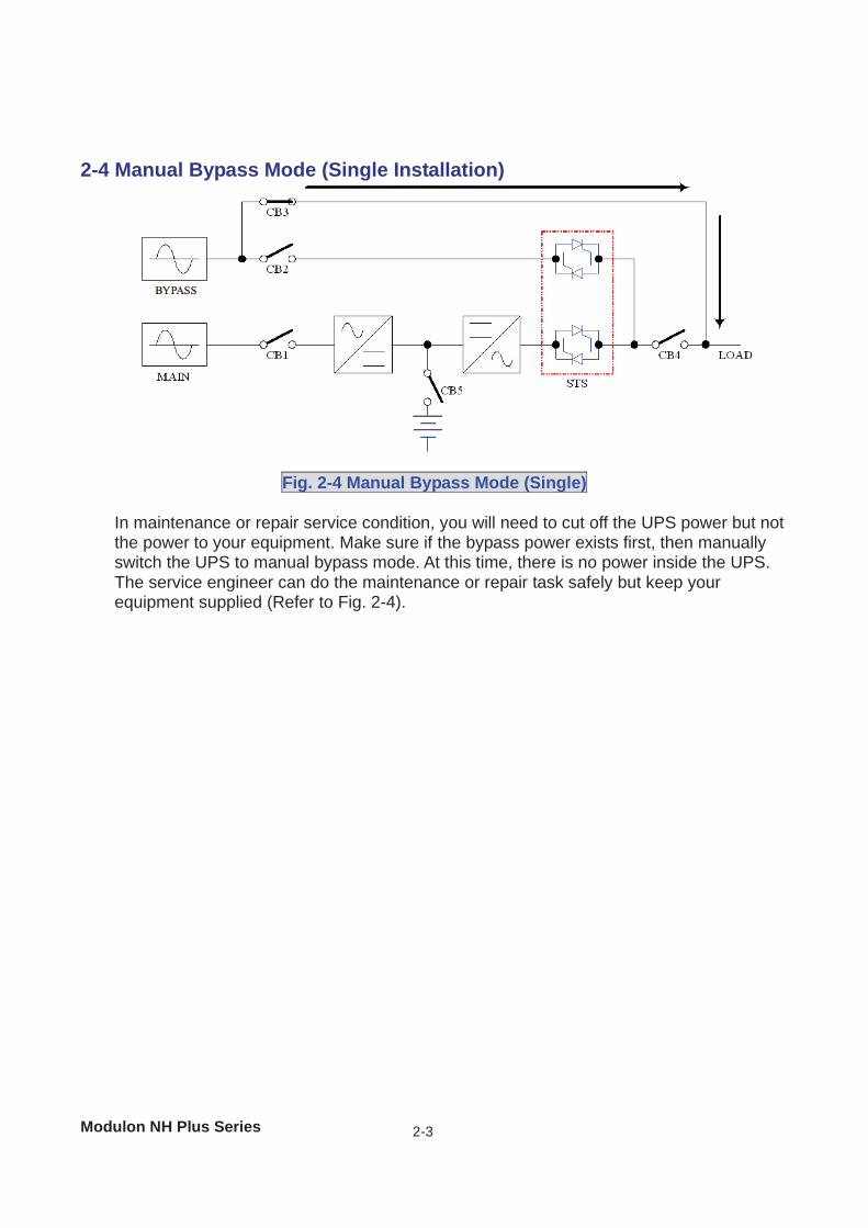
2-4 Manual Bypass Mode (Single Installation)
Fig. 2-4 Manual Bypass Mode (Single)
In maintenance or repair service condition, you will need to cut off the UPS power but not the power to your equipment. Make sure if the bypass power exists first, then manually switch the UPS to manual bypass mode. At this time, there is no power inside the UPS. The service engineer can do the maintenance or repair task safely but keep your equipment supplied (Refer to Fig. 2-4).
2 Operation
2-4
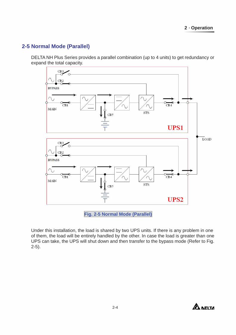
2-5 Normal Mode (Parallel)
DELTA NH Plus Series provides a parallel combination (up to 4 units) to get redundancy or expand the total capacity.
Fig. 2-5 Normal Mode (Parallel)
Under this installation, the load is shared by two UPS units. If there is any problem in one of them, the load will be entirely handled by the other. In case the load is greater than one UPS can take, the UPS will shut down and then transfer to the bypass mode (Refer to Fig. 2-5).
Modulon NH Plus Series 2-5
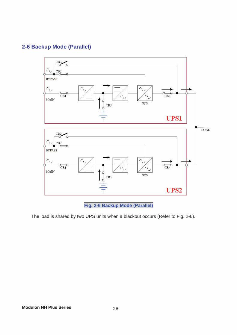
2-6 Backup Mode (Parallel)
Fig. 2-6 Backup Mode (Parallel)
The load is shared by two UPS units when a blackout occurs (Refer to Fig. 2-6).
2 Operation
2-6
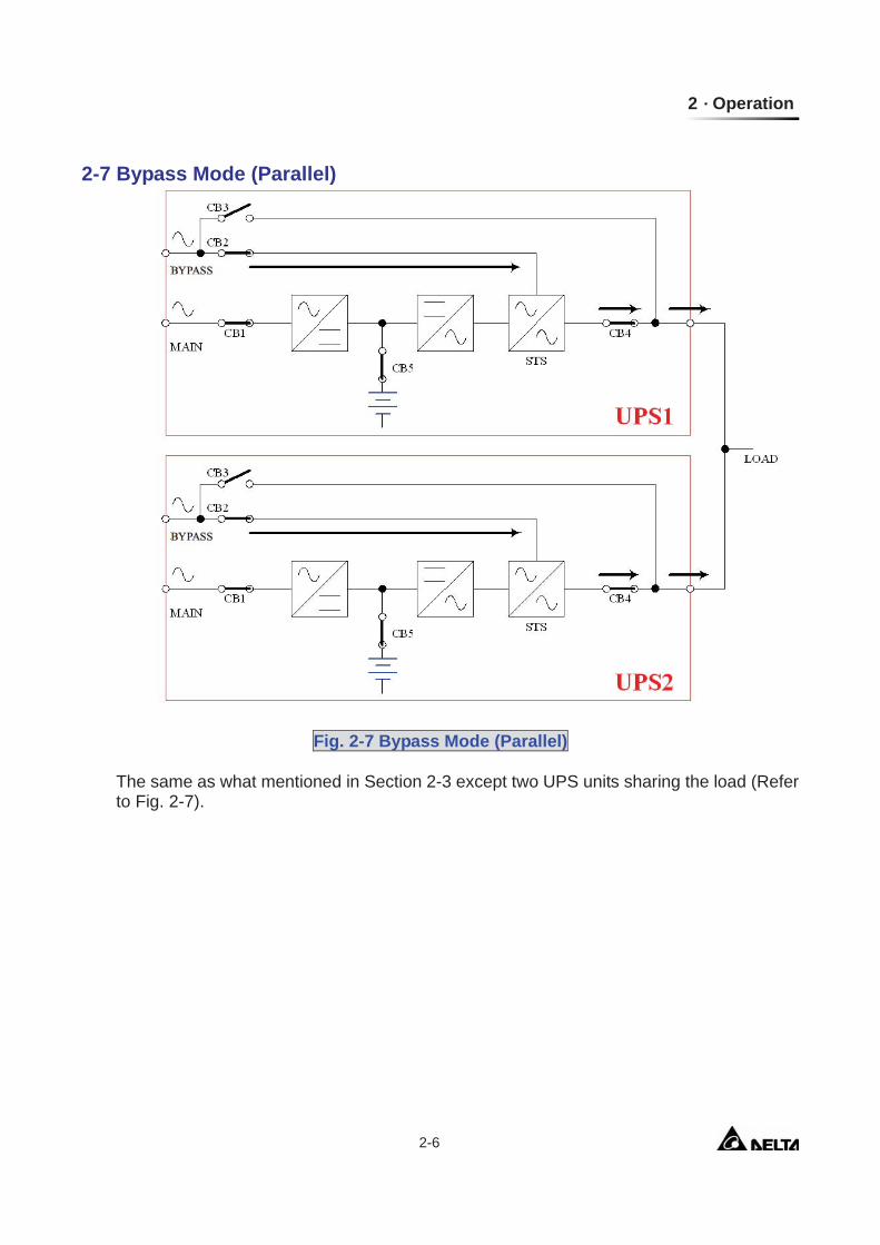
2-7 Bypass Mode (Parallel)
Fig. 2-7 Bypass Mode (Parallel)
The same as what mentioned in Section 2-3 except two UPS units sharing the load (Refer to Fig. 2-7).
Modulon NH Plus Series 2-7
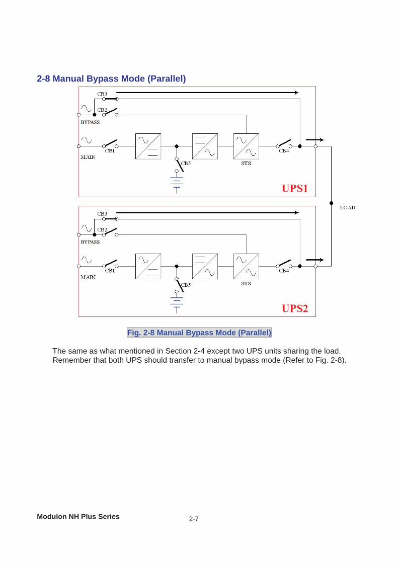
2-8 Manual Bypass Mode (Parallel)
Fig. 2-8 Manual Bypass Mode (Parallel)
The same as what mentioned in Section 2-4 except two UPS units sharing the load. Remember that both UPS should transfer to manual bypass mode (Refer to Fig. 2-8).
2 Operation
2-8
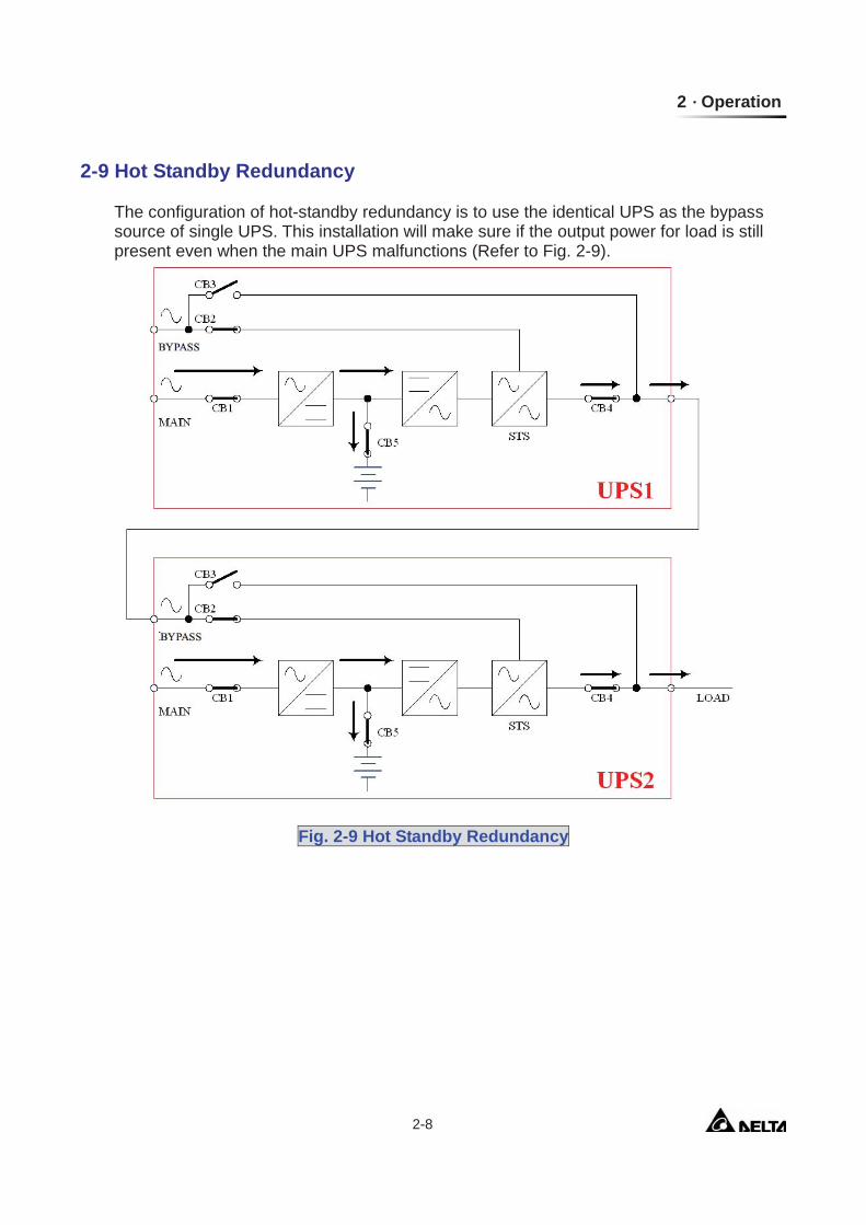
2-9 Hot Standby Redundancy
The configuration of hot-standby redundancy is to use the identical UPS as the bypass source of single UPS. This installation will make sure if the output power for load is still present even when the main UPS malfunctions (Refer to Fig. 2-9).
Fig. 2-9 Hot Standby Redundancy
Modulon NH Plus Series 3-1
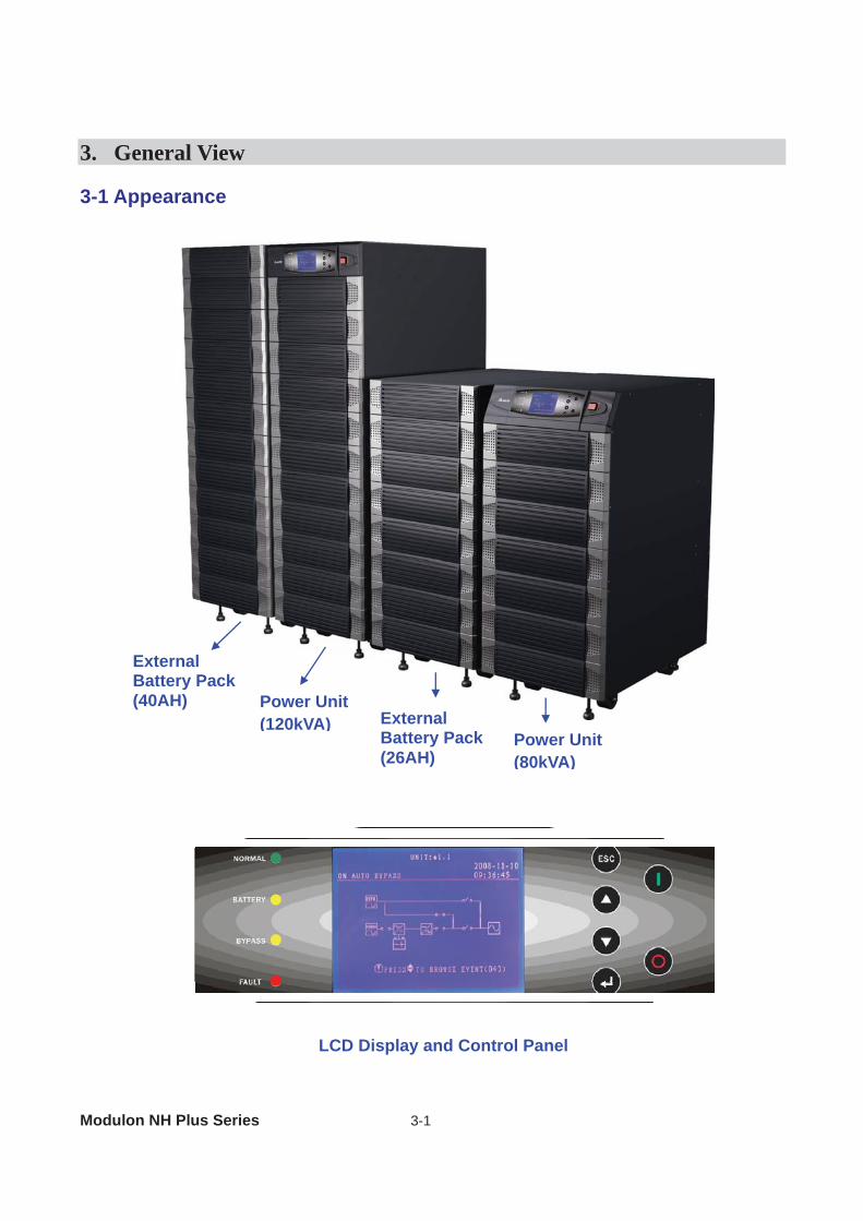
3. General View 3-1 Appearance
LCD Display and Control Panel
Power Unit (120kVA) External
Battery Pack(26AH)
Power Unit(80kVA)
External Battery Pack (40AH)
3 General View
3-2
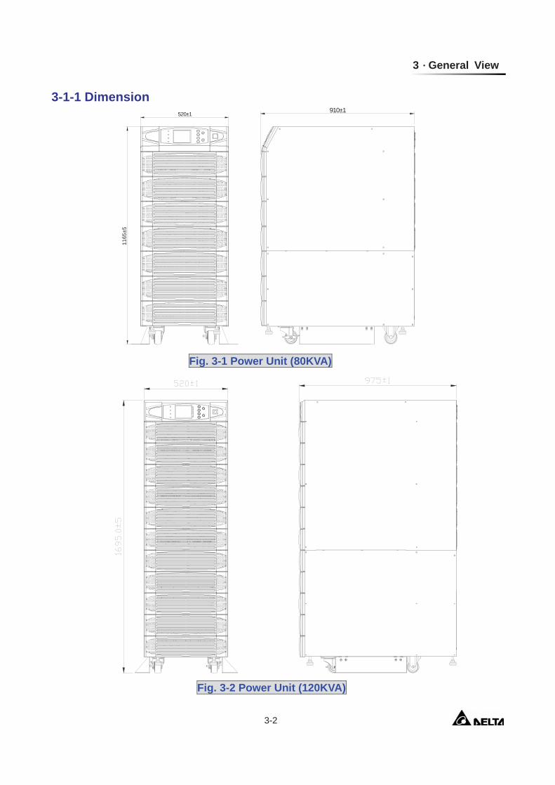
3-1-1 Dimension
Fig. 3-1 Power Unit (80KVA)
520±1
1165
±5
910±1
Fig. 3-2 Power Unit (120KVA)
Modulon NH Plus Series 3-3
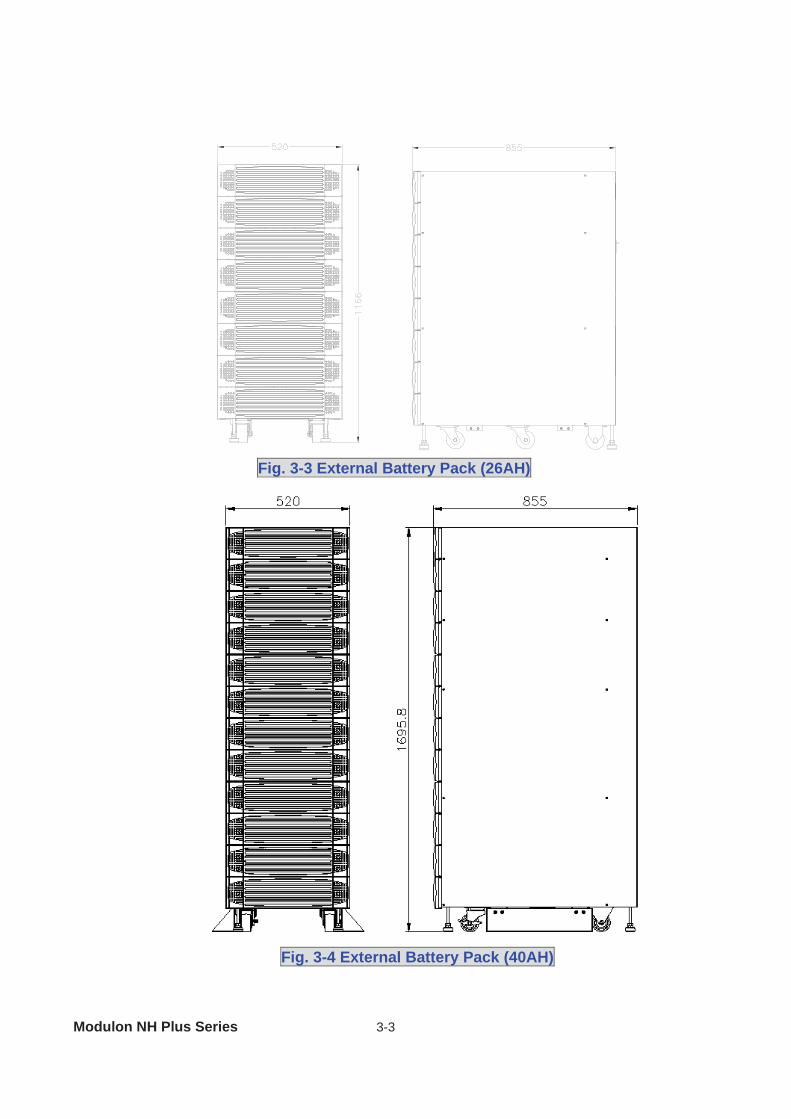
Fig. 3-3 External Battery Pack (26AH)
Fig. 3-4 External Battery Pack (40AH)
3 General View
3-4
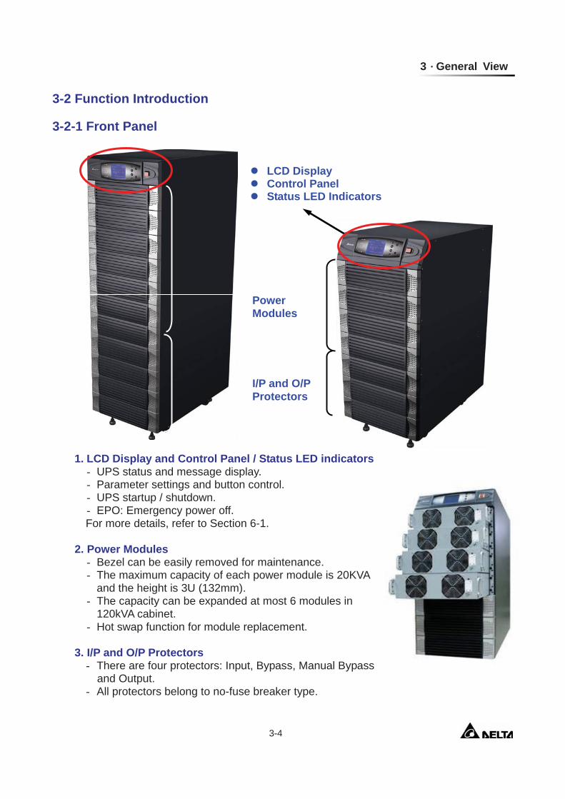
3-2 Function Introduction
3-2-1 Front Panel
1. LCD Display and Control Panel / Status LED indicators - UPS status and message display. - Parameter settings and button control. - UPS startup / shutdown. - EPO: Emergency power off.
For more details, refer to Section 6-1. 2. Power Modules
- Bezel can be easily removed for maintenance. - The maximum capacity of each power module is 20KVA
and the height is 3U (132mm). - The capacity can be expanded at most 6 modules in
120kVA cabinet. - Hot swap function for module replacement.
3. I/P and O/P Protectors
- There are four protectors: Input, Bypass, Manual Bypass and Output.
- All protectors belong to no-fuse breaker type.
LCD Display Control Panel Status LED Indicators
Power Modules
I/P and O/P Protectors

Modulon NH Plus Series 3-5
3-2-2 Rear Panel
1. Interfaces Provide multi-interface for monitoring and control purpose.
There are: (1) Two multi-function slots (SNMP card, Relay I/O control card and Mobus card are
optional accessories). (2) Parallel port. (3) Input and output dry contacts. (4) RS232: Delta software ”UPSentry Smart 2000” or “Insight Power Manager” is the
optional choice for central monitoring and control purpose. For more details, refer to Section 3-3. 2. Power modules
- Remove the cover, then you can perform wiring for power modules. 3. Wiring terminal block
Interface
Wiring Terminal Block
Caster & Stop
Power Modules
Fig. 3-5 Rear view of NH Plus
3 General View
3-6
- Remove the cover, then you can perform wiring for input, output and external battery. - Input power source: 3 phases (R, S, T and neutral N). - Bypass input source: 3 Phases (R, S, T and neutral N). - External battery pack: positive (+), negative (-) and neutral N. - UPS output: 3 Phases (R, S, T and neutral N). - Protection Earth: For safety considerations.
Different regions may have their own markings of power phases. The following table is a cross reference for possible use.
Three Phase America / Asia Europe L1 R U L2 S V L3 T W
4. Caster & Stop:
- Move the UPS for short distance. - Casters with stop function.
- Adjustable leveler for stabilization. - Balance supporter for safety.
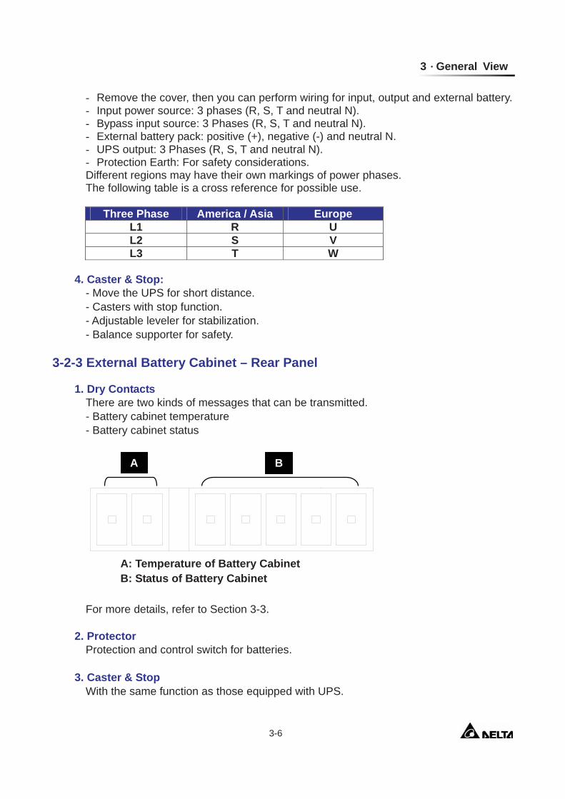
3-2-3 External Battery Cabinet – Rear Panel
1. Dry Contacts
There are two kinds of messages that can be transmitted. - Battery cabinet temperature - Battery cabinet status
For more details, refer to Section 3-3.
2. Protector Protection and control switch for batteries. 3. Caster & Stop With the same function as those equipped with UPS.
A B
A: Temperature of Battery Cabinet B: Status of Battery Cabinet
Modulon NH Plus Series 3-7
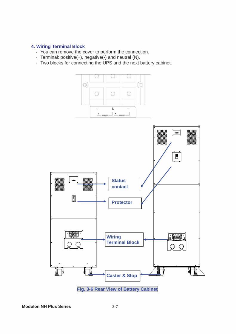
4. Wiring Terminal Block
- You can remove the cover to perform the connection. - Terminal: positive(+), negative(-) and neutral (N). - Two blocks for connecting the UPS and the next battery cabinet.
Protector
Caster & Stop
Wiring Terminal Block
Fig. 3-6 Rear View of Battery Cabinet
Status contact
3 General View
3-8
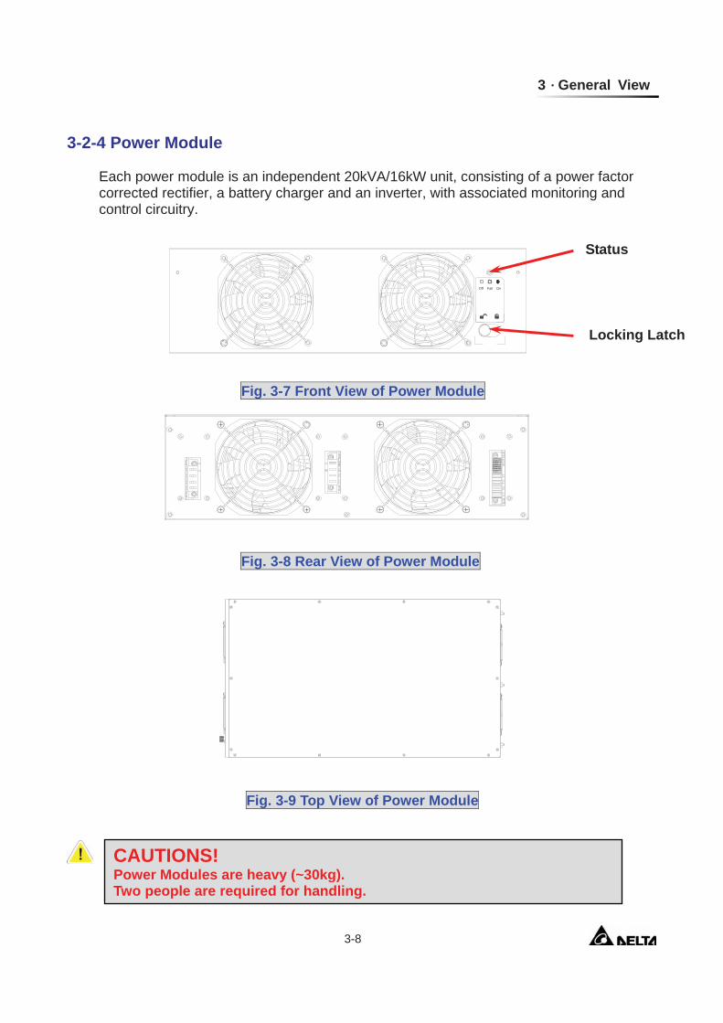
3-2-4 Power Module
Each power module is an independent 20kVA/16kW unit, consisting of a power factor corrected rectifier, a battery charger and an inverter, with associated monitoring and control circuitry.
Fail OnOff
Status
Locking Latch
Fig. 3-7 Front View of Power Module
Fig. 3-8 Rear View of Power Module
Fig. 3-9 Top View of Power Module
CAUTIONS! Power Modules are heavy (~30kg). Two people are required for handling.
Modulon NH Plus Series 3-9
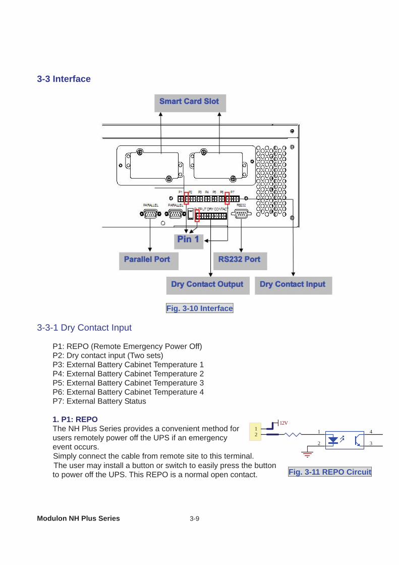
3-3 Interface
Fig. 3-10 Interface 3-3-1 Dry Contact Input
P1: REPO (Remote Emergency Power Off) P2: Dry contact input (Two sets) P3: External Battery Cabinet Temperature 1 P4: External Battery Cabinet Temperature 2 P5: External Battery Cabinet Temperature 3 P6: External Battery Cabinet Temperature 4 P7: External Battery Status
1. P1: REPO The NH Plus Series provides a convenient method for users remotely power off the UPS if an emergency event occurs. Simply connect the cable from remote site to this terminal. The user may install a button or switch to easily press the button to power off the UPS. This REPO is a normal open contact.
12
12V
1
2
4
3
Fig. 3-11 REPO Circuit
3 General View
3-10
1234
12V
12V
1
2
4
3
1
2
4
3
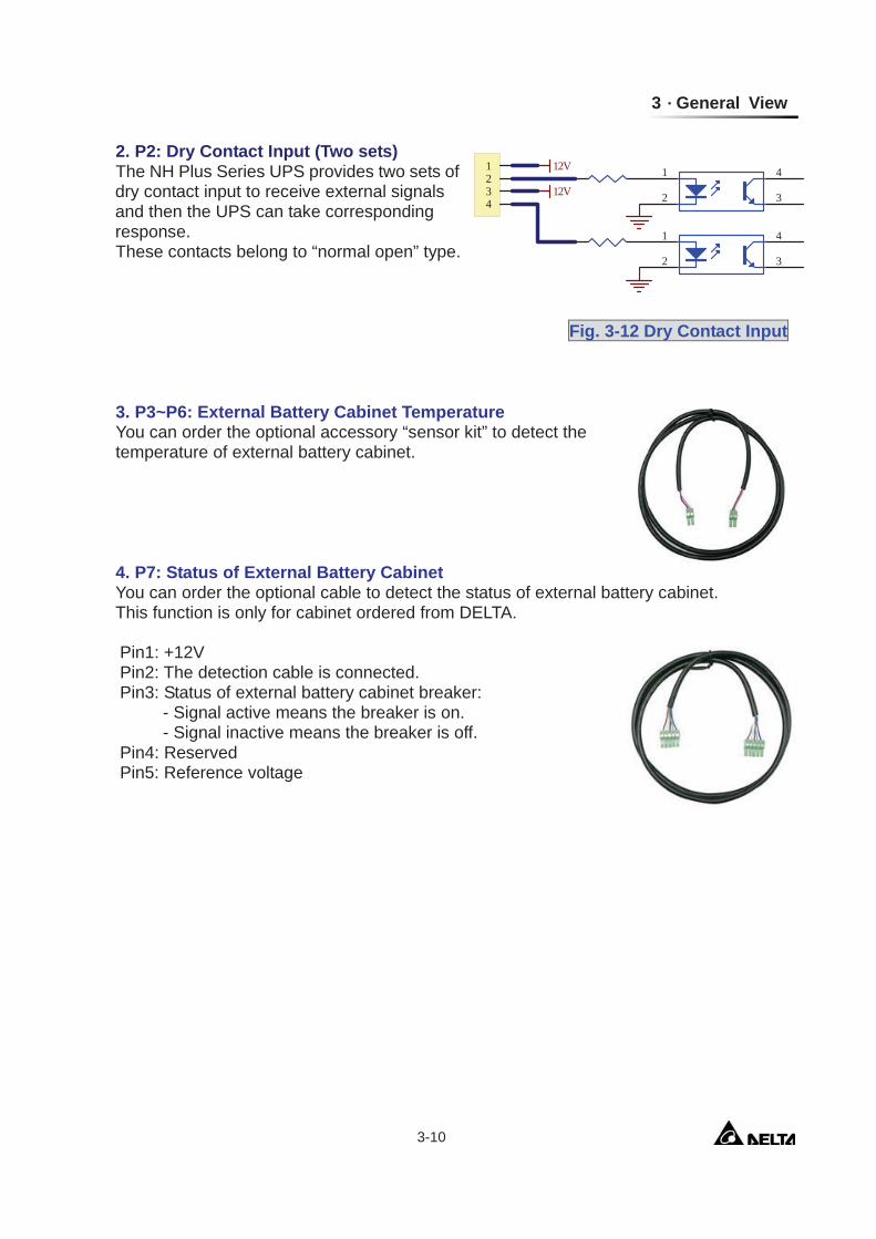
2. P2: Dry Contact Input (Two sets) The NH Plus Series UPS provides two sets of dry contact input to receive external signals and then the UPS can take corresponding response. These contacts belong to “normal open” type.
3. P3~P6: External Battery Cabinet Temperature You can order the optional accessory “sensor kit” to detect the temperature of external battery cabinet.
4. P7: Status of External Battery Cabinet You can order the optional cable to detect the status of external battery cabinet. This function is only for cabinet ordered from DELTA.
Pin1: +12V Pin2: The detection cable is connected. Pin3: Status of external battery cabinet breaker: - Signal active means the breaker is on. - Signal inactive means the breaker is off. Pin4: Reserved Pin5: Reference voltage
Fig. 3-12 Dry Contact Input
Modulon NH Plus Series 3-11
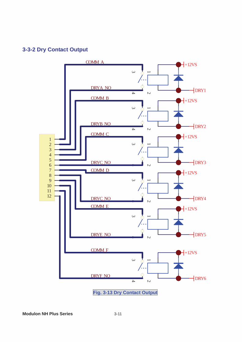
3-3-2 Dry Contact Output
Fig. 3-13 Dry Contact Output
34
12
+12VS
DRY1
34
12
+12VS
DRY2
34
12
+12VS
DRY3
34
12
+12VS
DRY4
34
12
+12VS
DRY5
34
12
+12VS
DRY6
123456789
101112
COMM_A
COMM_B
DRYA_NO
DRYB_NO
COMM_C
COMM_D
DRYC_NO
DRYC_NO
DRYE_NO
DRYF_NO
COMM_E
COMM_F
3 General View
3-12
The NH Plus Series UPS provides 6 dry contact outputs. These contacts can be set to
normally open or normally close. The default message is shown in the table below.
There are other 13 choices as shown below. Contact Message Description 7. Internal communication
failure The communication of module is abnormal.
8. External parallel communication failure
During installation of the parallel redundancy, the parallel communication is abnormal.
9. Output overload warning/shutdown
The loading is over rated output of the UPS.
10. Power module fault shutdown The module fails and the UPS is shut down. 11. Power module warning The module has errors, but the UPS can still function normally.12. EPO activated Urgently power off the UPS. 13. Load on manual bypass The UPS transfers to manual bypass mode. 14. Battery cabinet over
temperature warning/shutdown
The temperature is too high.
15. Output voltage abnormal The output voltage is too high or too low. 16. Battery need replace Overdue for battery replacement (Compared with system
setup.) 17. Bypass over temperature
warning/shutdown Bypass “static transfer switch” is over temperature.
18. Battery ground fault Grounding error 19. Bypass static switch fault The bypass “static transfer switch” is abnormal.
Contact Message Description Pin1-2 Load on inverter The UPS is working normally. Pin3-4 Load on auto bypass The UPS is in bypass mode. Pin5-6 Mains1 input fails when
loading on inverter The Utility is blackout or abnormal. The UPS is in backup mode.
Pin7-8 Battery low The UPS is in backup mode, and the battery voltage is closed to the terminative limit. (The battery voltage is lower than 220V.)
Pin9-10 Bypass input abnormal The bypass is abnormal (frequency, phase), and the output frequency will follow the rating.
Pin11-12 Battery test failure Performs the battery test. The battery voltage is lower than the default value.
Modulon NH Plus Series 3-13
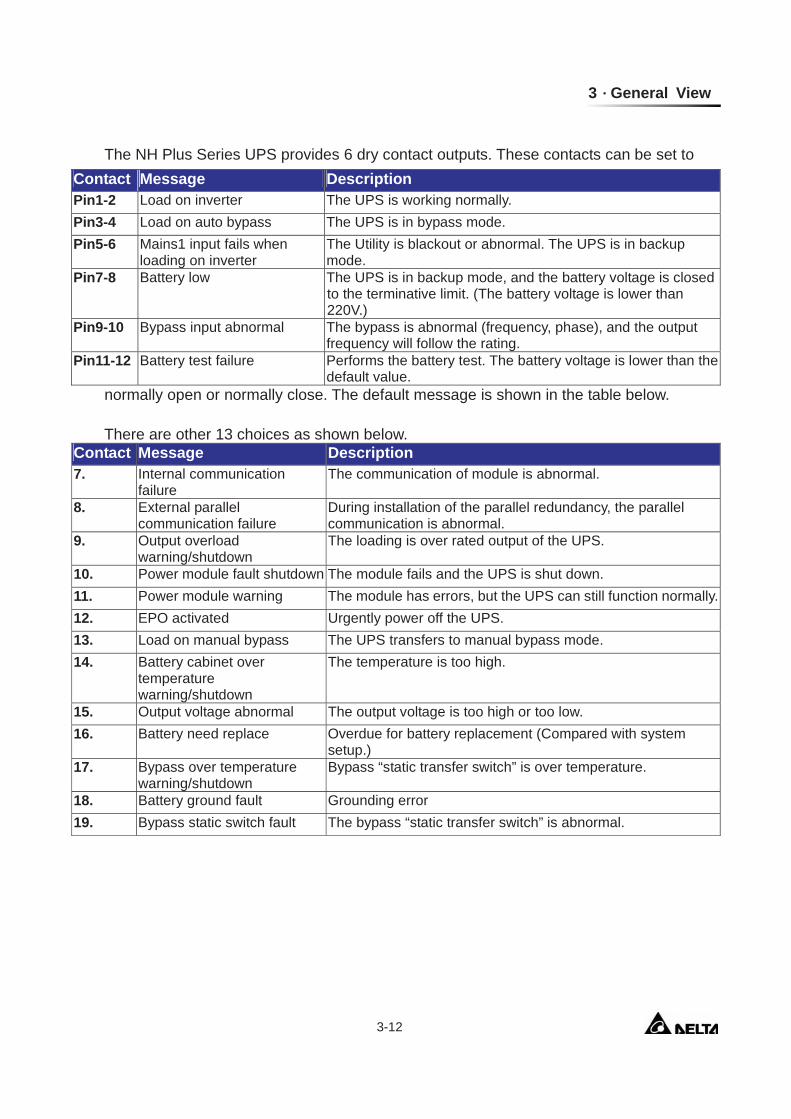
3-3-3 RS232 Port
Use a RS232 cable to connect the computer. DELTA develops various powerful software such as “UPSentry Smart 2000” and “InsightPower Manager” to integrate the UPS into your system. For more details, refer to Chapter 7.
3-3-4 Parallel Port
For redundancy or expansion installation, you simply connect two UPSs via a parallel communication cable.
3-3-5 Smart Card Slot
The NH Plus Series UPS provides two smart slots. DELTA develops many powerful smart cards for various applications. There are 5 accessories available as below.
Please contact your local dealer or agent for orders.
Smart Card Part No. SNMP Card 3915100120-S Programmable Relay I/O Card
3915100147-S
ModBUS Card 3915100422-S Environmental Sensor 3915100423-S SNMP+Switching Hub 3915100514-S
162738495
TX
RX
Fig. 3-14 RS232
Use the parallel communication cable in the accessory pack. Linking the UPS with other cables will result in accidents.
3 General View
3-14
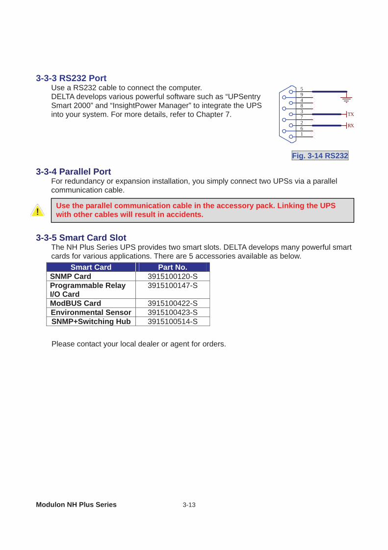
1. SNMP Card (Part No.: 3915100120-S)
Features: SNMP agent and web server implemented in UPS supporting the following protocols:
ARP, IP, ICMP, SNMPv1, SNMPv3 USM, UDP, TCP, HTTP, FTP, TFTP, SMTP, BOOTP, SNTP, DN and Telnet.
Security login by MD5 . User level management. Firmware upgrade for new features through TFTP. Batch configuration through FTP. Save event logs and history values of UPS in EEPROM. Scheduled UPS shutdown, restart and test. Wake-On-LAN packet to wake up PC. Send the e-mail and SNMP trap to notify users. Provides InsightPower Client software to protect public operating systems. Provides InsightPower Manager to monitor all the UPS information in the network. Provides the InsightPower EzSetting software to easily configure for the first time and
upgrade firmware.
Golden Finger: 12V DC, Communicate with UPS.
Dip Switch: Normal, Configuration, Pass Through and Sensor modes.
Reset: Reset SNMP. card.
Console Port: Connect the HyperTerminal for configuration or Sensor Box for environmental monitoring.
RJ45 Network Port: 10/100 M Auto-Negotiation Ethernet interface.
Modulon NH Plus Series 3-15
Technical Specification Network Connection RJ-45
Temperature 0~40°C
Humidity 10~80% (Relative)
Input Power 9~24V DC
Power Consumption 1 Watt (Maximum)
Dimension (L x W) 130 x 60 mm
Weight 58g
Dip Switch Mode SW1 SW2 Mode
ON ON Configuration
ON OFF For Environmental Sensor
OFF ON Pass Through
OFF OFF Normal
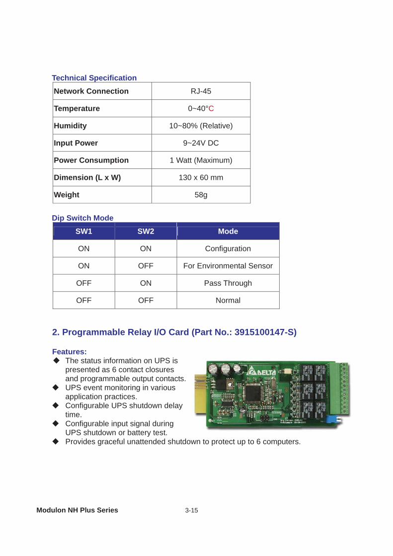
2. Programmable Relay I/O Card (Part No.: 3915100147-S)
Features: The status information on UPS is
presented as 6 contact closures and programmable output contacts.
UPS event monitoring in various application practices.
Configurable UPS shutdown delay time.
Configurable input signal during UPS shutdown or battery test.
Provides graceful unattended shutdown to protect up to 6 computers.
3 General View
3-16
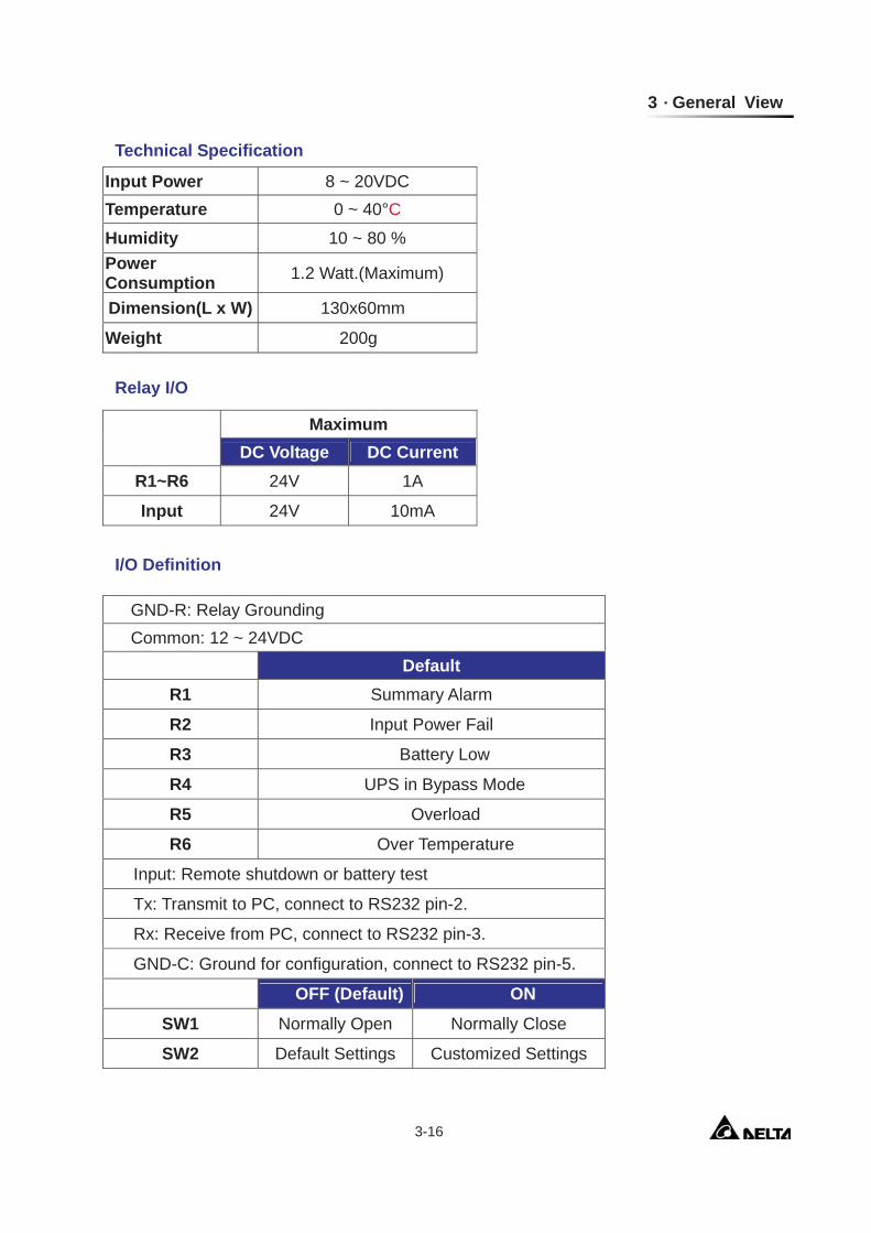
Technical Specification
Relay I/O
I/O Definition
Input Power 8 ~ 20VDC Temperature 0 ~ 40°C
Humidity 10 ~ 80 % Power Consumption 1.2 Watt.(Maximum)
Dimension(L x W) 130x60mm
Weight 200g
Maximum
DC Voltage DC Current R1~R6 24V 1A
Input 24V 10mA
GND-R: Relay Grounding Common: 12 ~ 24VDC
Default R1 Summary Alarm
R2 Input Power Fail
R3 Battery Low
R4 UPS in Bypass Mode
R5 Overload
R6 Over Temperature
Input: Remote shutdown or battery test
Tx: Transmit to PC, connect to RS232 pin-2.
Rx: Receive from PC, connect to RS232 pin-3.
GND-C: Ground for configuration, connect to RS232 pin-5.
OFF (Default) ON
SW1 Normally Open Normally Close
SW2 Default Settings Customized Settings
Modulon NH Plus Series 3-17
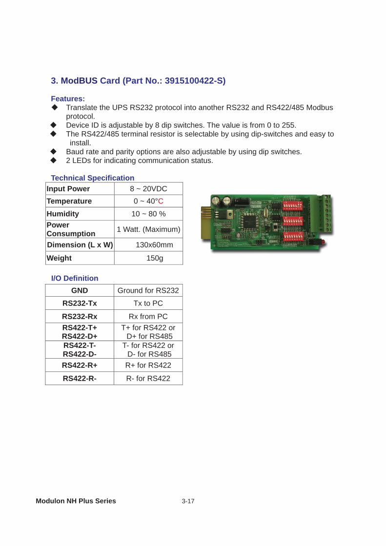
3. ModBUS Card (Part No.: 3915100422-S)
Features: Translate the UPS RS232 protocol into another RS232 and RS422/485 Modbus
protocol. Device ID is adjustable by 8 dip switches. The value is from 0 to 255. The RS422/485 terminal resistor is selectable by using dip-switches and easy to
install. Baud rate and parity options are also adjustable by using dip switches. 2 LEDs for indicating communication status.
Technical Specification
I/O Definition
Input Power 8 ~ 20VDC Temperature 0 ~ 40°C
Humidity 10 ~ 80 % Power Consumption 1 Watt. (Maximum)
Dimension (L x W) 130x60mm
Weight 150g
GND Ground for RS232
RS232-Tx Tx to PC
RS232-Rx Rx from PC RS422-T+ RS422-D+
T+ for RS422 or D+ for RS485
RS422-T- RS422-D-
T- for RS422 or D- for RS485
RS422-R+ R+ for RS422
RS422-R- R- for RS422
3 General View
3-18
3-4 Other Optional Accessories
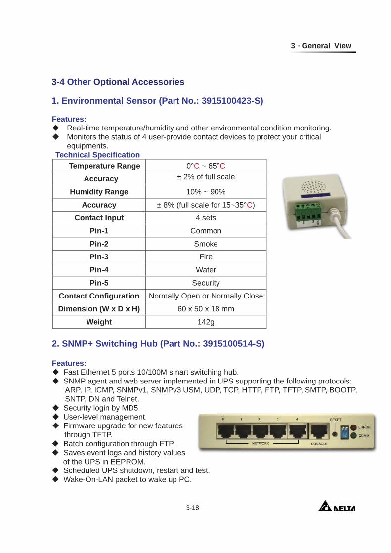
1. Environmental Sensor (Part No.: 3915100423-S)
Features: Real-time temperature/humidity and other environmental condition monitoring. Monitors the status of 4 user-provide contact devices to protect your critical
equipments. Technical Specification
Temperature Range 0°C ~ 65°C
Accuracy ± 2% of full scale
Humidity Range 10% ~ 90%
Accuracy ± 8% (full scale for 15~35°C)
Contact Input 4 sets
Pin-1 Common
Pin-2 Smoke
Pin-3 Fire
Pin-4 Water
Pin-5 Security
Contact Configuration Normally Open or Normally Close
Dimension (W x D x H) 60 x 50 x 18 mm
Weight 142g
2. SNMP+ Switching Hub (Part No.: 3915100514-S)
Features: Fast Ethernet 5 ports 10/100M smart switching hub. SNMP agent and web server implemented in UPS supporting the following protocols:
ARP, IP, ICMP, SNMPv1, SNMPv3 USM, UDP, TCP, HTTP, FTP, TFTP, SMTP, BOOTP, SNTP, DN and Telnet.
Security login by MD5. User-level management. Firmware upgrade for new features
through TFTP. Batch configuration through FTP. Saves event logs and history values of the UPS in EEPROM.
Scheduled UPS shutdown, restart and test. Wake-On-LAN packet to wake up PC.
Modulon NH Plus Series 3-19
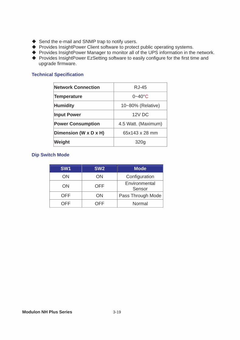
Send the e-mail and SNMP trap to notify users. Provides InsightPower Client software to protect public operating systems. Provides InsightPower Manager to monitor all of the UPS information in the network. Provides InsightPower EzSetting software to easily configure for the first time and upgrade firmware.
Technical Specification
Network Connection RJ-45
Temperature 0~40°C
Humidity 10~80% (Relative)
Input Power 12V DC
Power Consumption 4.5 Watt. (Maximum)
Dimension (W x D x H) 65x143 x 28 mm
Weight 320g
Dip Switch Mode
SW1 SW2 Mode ON ON Configuration
ON OFF Environmental Sensor
OFF ON Pass Through Mode
OFF OFF Normal
3 General View
3-20
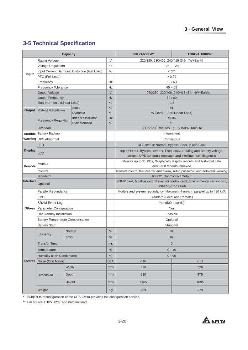
3-5 Technical Specification
* Subject to reconfiguration of the UPS; Delta provides the configuration service. ** For source THDV <2 and nominal load.
Capacity 80KVA/72KW* 120KVA/108KW*
Input
Rating Voltage V 220/380, 230/400, 240/415 (3 4W+Earth)
Voltage Regulation % -25 ~ +20 Input Current Harmonic Distortion (Full Load) % < 3**
PFC (Full Load) > 0.99 Frequency Hz 50 / 60 Frequency Tolerance Hz 45 ~ 65
Output
Output Voltage V 220/380, 230/400, 240/415 (3 4W+Earth) Output Frequency Hz 50 / 60 Total Harmonic (Linear Load) % 3
Voltage Regulation Static % 1 Dynamic % 7 (10% ~ 90% Linear Load)
Frequency Regulation Interior Oscillator Hz 0.05 Synchronized % 5
Overload 125%: 10minutes ; 150%: 1minute
Audible Warning
Battery Backup Intermittent
UPS Abnormal Continuous
Display LED UPS status: Normal, Bypass, Backup and Fault
LCD Input/Output, Bypass, Inverter, Frequency, Loading and Battery voltage,
current, UPS abnormal message and intelligent self diagnosis
Remote Monitor
Monitor up to 31 PCs, Graphically display records and historical data and Fault records retrieved
Control Remote control the Inverter and alarm, setup password and auto-dial warning
Interface Standard RS232, Dry Contact Output
Optional SNMP card, Modbus card, Relay I/O control card, Environmental sensor box,
SNMP+5 Ports Hub
Others
Parallel Redundancy Module and system redundancy; Maximum 4 units in parallel up to 480 kVA
EPO Standard (Local and Remote)
SRAM Event Log Yes (500 records)
Parameter Configuration Yes
Hot Standby Installation Feasible
Battery Temperature Compensation Optional
Battery Start Standard
Overall
Efficiency Normal % 94
ECO % 97
Transfer Time ms 0
Temperature °C 0 40
Humidity (Non Condensed) % 0 95
Noise (One Meter) dBA < 64 < 67
Dimension
Width mm 520 520
Depth mm 910 975
Height mm 1165 1695
Weight Kg 259 379
Modulon NH Plus Series 4-1
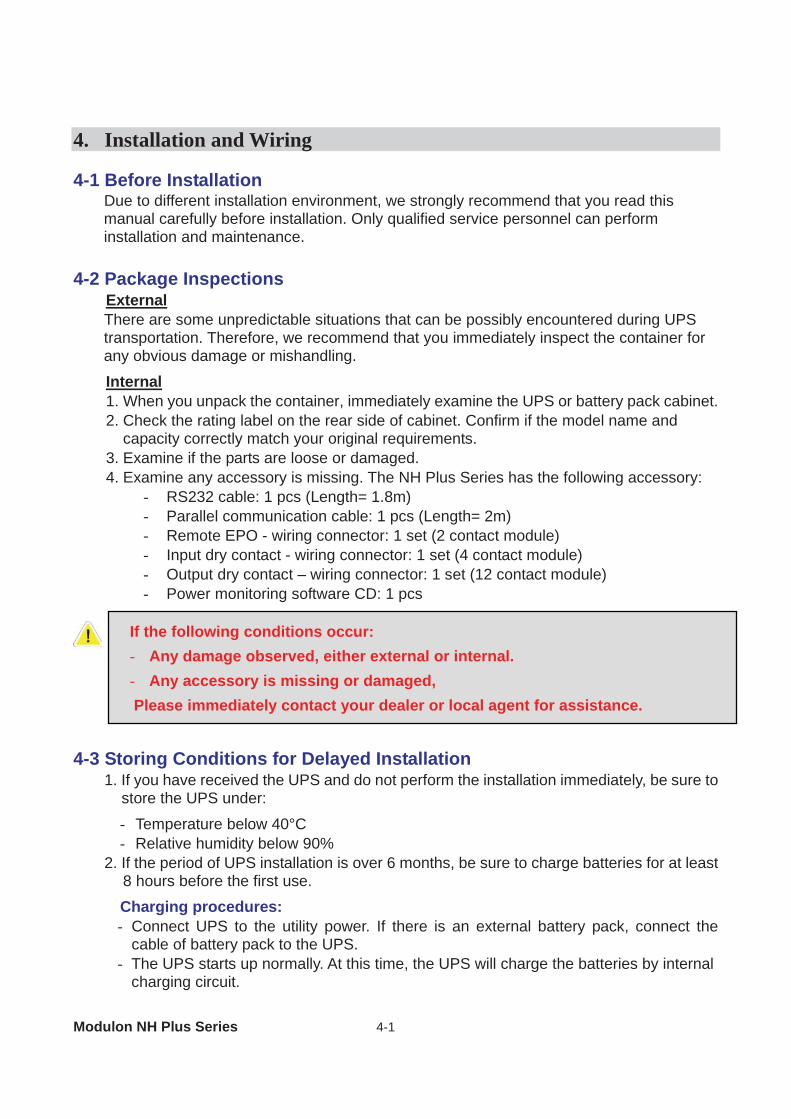
4. Installation and Wiring 4-1 Before Installation
Due to different installation environment, we strongly recommend that you read this manual carefully before installation. Only qualified service personnel can perform installation and maintenance.
4-2 Package Inspections
External There are some unpredictable situations that can be possibly encountered during UPS transportation. Therefore, we recommend that you immediately inspect the container for any obvious damage or mishandling.
Internal 1. When you unpack the container, immediately examine the UPS or battery pack cabinet. 2. Check the rating label on the rear side of cabinet. Confirm if the model name and
capacity correctly match your original requirements. 3. Examine if the parts are loose or damaged. 4. Examine any accessory is missing. The NH Plus Series has the following accessory:
- RS232 cable: 1 pcs (Length= 1.8m) - Parallel communication cable: 1 pcs (Length= 2m) - Remote EPO - wiring connector: 1 set (2 contact module) - Input dry contact - wiring connector: 1 set (4 contact module) - Output dry contact – wiring connector: 1 set (12 contact module) - Power monitoring software CD: 1 pcs
4-3 Storing Conditions for Delayed Installation
1. If you have received the UPS and do not perform the installation immediately, be sure to store the UPS under:
- Temperature below 40°C - Relative humidity below 90%
2. If the period of UPS installation is over 6 months, be sure to charge batteries for at least 8 hours before the first use.
Charging procedures: - Connect UPS to the utility power. If there is an external battery pack, connect the
cable of battery pack to the UPS. - The UPS starts up normally. At this time, the UPS will charge the batteries by internal
charging circuit.
If the following conditions occur: - Any damage observed, either external or internal. - Any accessory is missing or damaged,
Please immediately contact your dealer or local agent for assistance.
4 Installation and Wiring
4-2
3. The carton and the original packaging must remain sealed to prevent any possible damage from mouse or similar creatures.
4-4 Installation Environment and Position
4-4-1 Handling Safety 1. The NH Plus series UPS is equipped with casters so that you can roll the UPS in a short
distance to the desired location. During unpacking process, be sure to make full use of manpower and a suitable machine (such as stacker) with sufficient capacity to carefully move the UPS.
2. Casters are only suitable for moving on even surface. Avoid moving the UPS on bumpy route, because this may cause damage of UPS or tip-over accident.
3. Push the UPS from either front or rear side otherwise could cause tip-over accident.
4. When the UPS needs a long-distance movement, make use of a suitable machine but not casters of the UPS.
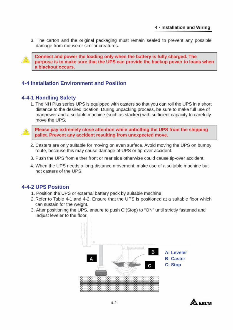
4-4-2 UPS Position
1. Position the UPS or external battery pack by suitable machine. 2. Refer to Table 4-1 and 4-2. Ensure that the UPS is positioned at a suitable floor which
can sustain for the weight. 3. After positioning the UPS, ensure to push C (Stop) to “ON” until strictly fastened and
adjust leveler to the floor.
Connect and power the loading only when the battery is fully charged. The purpose is to make sure that the UPS can provide the backup power to loads when a blackout occurs.
Please pay extremely close attention while unbolting the UPS from the shipping pallet. Prevent any accident resulting from unexpected move.
A: Leveler B: Caster C: Stop
A C
B
Modulon NH Plus Series 4-3
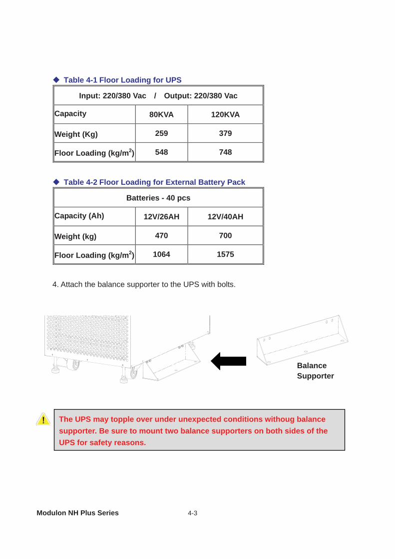
Table 4-1 Floor Loading for UPS
Input: 220/380 Vac / Output: 220/380 Vac Capacity 80KVA 120KVA
Weight (Kg) 259 379
Floor Loading (kg/m2) 548 748
Table 4-2 Floor Loading for External Battery Pack
Batteries - 40 pcs
Capacity (Ah) 12V/26AH 12V/40AH
Weight (kg) 470 700
Floor Loading (kg/m2) 1064 1575
4. Attach the balance supporter to the UPS with bolts.
Balance Supporter
The UPS may topple over under unexpected conditions withoug balance supporter. Be sure to mount two balance supporters on both sides of the UPS for safety reasons.
4 Installation and Wiring
4-4
4-4-3 Installation Environment 1. The NH Plus series UPS is for in-house use only. The installation space should be
conditioned at temperature of 25°C and relative humidity of <90%. And the maximum operation altitude is 3000 m.
2. The circumstance surrounding the UPS should be kept clean. Prevent any possible damage from mouse or similar objects.
3. The NH Plus Series UPS requires good ventilation and heat dissipation. It features fans for heat dissipation. The air flow circulates from front to the rear bezel. Therefore, we strongly recommend the following:
(1) A clearance of at least 100cm in front of UPS should be provided to permit free 9*passage of service engineer and ventilation purpose.
(2) A clearance of at least 50cm between rear bezel of UPS and wall should be provided to permit free passage of service engineer and ventilation purpose.
(3) A clearance of at least 50cm between the top of UPS and the ceiling should be provided to permit free passage of service engineer.
(4) A clearance of at least 100cm in front of external battery cabinet should be provided for maintenance and at least 50cm between rear bezel and the wall should be provided for ventilation.
4. It is recommended that you install fire extinguisher beside the UPS for emergency use.
Do not use any air conditioning or similar facility that blows air directly onto the rear side of the UPS.
Modulon NH Plus Series 4-5
4-5 Wiring 4-5-1 Preparations
1. De-energize all input (AC or DC) or output power of the UPS before installing cables
or making any electrical connection. 2. Ensure that all cables are correctly marked according to the purpose, as well as the
polarity, phase and diameter. 3. If the input/output power of the UPS is WYE-WYE (Y connection), ”Neutral”
and ”Ground” should not be connected. If the input power has VNG>0, and client requested the VNG must be 0 volt inside the UPS , the solution is to install an isolation transformer before UPS and input power source. Then, connect “Neutral” and “Ground” of the UPS together.
4. Make use of suitable conduits and gland to protect I/O wiring according to local regulations. Refer to Table 4-3.
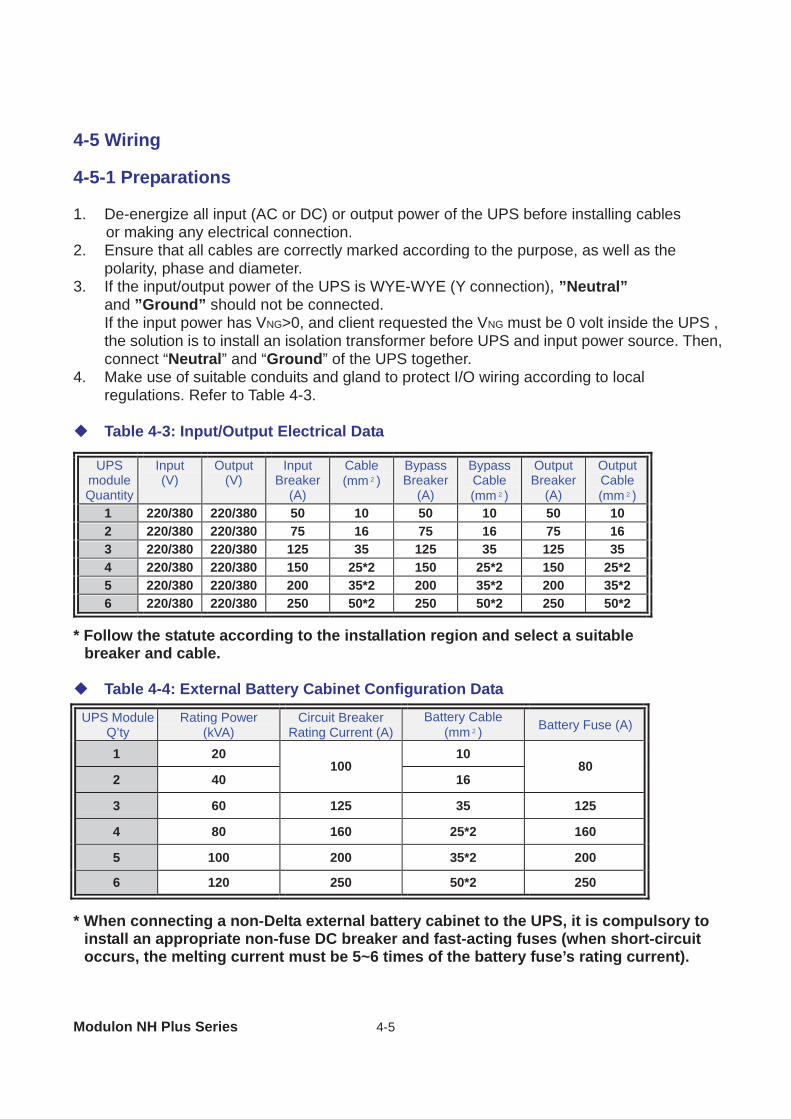
Table 4-3: Input/Output Electrical Data
* Follow the statute according to the installation region and select a suitable breaker and cable.
Table 4-4: External Battery Cabinet Configuration Data
* When connecting a non-Delta external battery cabinet to the UPS, it is compulsory to install an appropriate non-fuse DC breaker and fast-acting fuses (when short-circuit occurs, the melting current must be 5~6 times of the battery fuse’s rating current).
UPS module Quantity
Input (V)
Output (V)
Input Breaker
(A)
Cable (mm²)
Bypass Breaker
(A)
Bypass Cable (mm²)
Output Breaker
(A)
Output Cable (mm²)
1 220/380 220/380 50 10 50 10 50 10 2 220/380 220/380 75 16 75 16 75 16 3 220/380 220/380 125 35 125 35 125 35 4 220/380 220/380 150 25*2 150 25*2 150 25*2 5 220/380 220/380 200 35*2 200 35*2 200 35*2 6 220/380 220/380 250 50*2 250 50*2 250 50*2
UPS Module Q’ty
Rating Power (kVA)
Circuit Breaker Rating Current (A)
Battery Cable (mm²) Battery Fuse (A)
1 20 10
2 40 100
16 80
3 60 125 35 125
4 80 160 25*2 160
5 100 200 35*2 200
6 120 250 50*2 250
4 Installation and Wiring
4-6
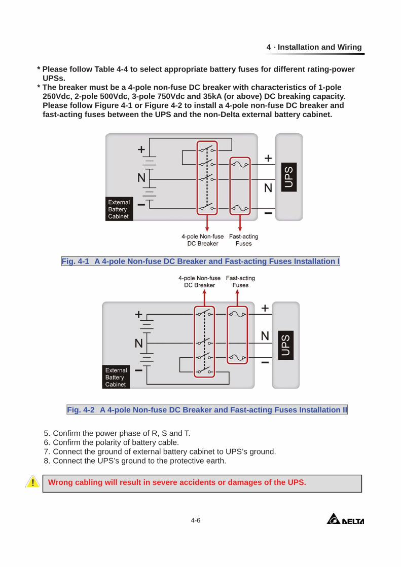
* Please follow Table 4-4 to select appropriate battery fuses for different rating-power UPSs.
* The breaker must be a 4-pole non-fuse DC breaker with characteristics of 1-pole 250Vdc, 2-pole 500Vdc, 3-pole 750Vdc and 35kA (or above) DC breaking capacity. Please follow Figure 4-1 or Figure 4-2 to install a 4-pole non-fuse DC breaker and fast-acting fuses between the UPS and the non-Delta external battery cabinet.
Fig. 4-1 A 4-pole Non-fuse DC Breaker and Fast-acting Fuses Installation I
Fig. 4-2 A 4-pole Non-fuse DC Breaker and Fast-acting Fuses Installation II
5. Confirm the power phase of R, S and T. 6. Confirm the polarity of battery cable. 7. Connect the ground of external battery cabinet to UPS’s ground. 8. Connect the UPS’s ground to the protective earth.
Wrong cabling will result in severe accidents or damages of the UPS.
Modulon NH Plus Series 4-7
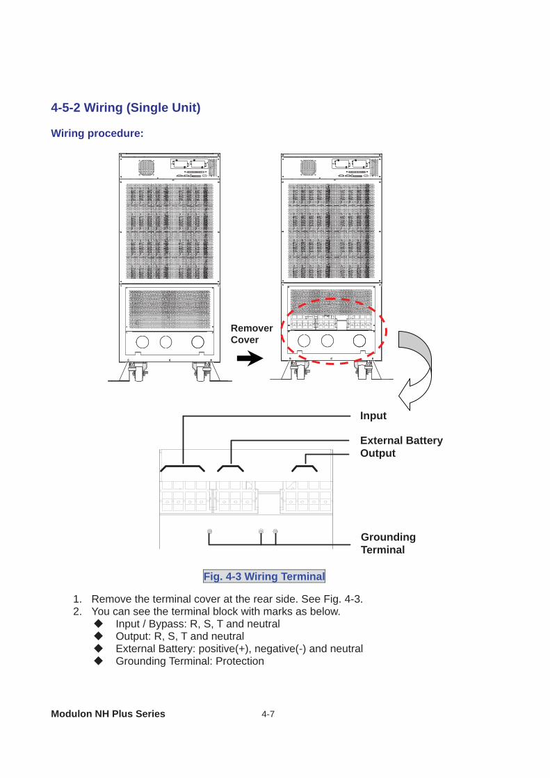
4-5-2 Wiring (Single Unit) Wiring procedure:
1. Remove the terminal cover at the rear side. See Fig. 4-3. 2. You can see the terminal block with marks as below.
Input / Bypass: R, S, T and neutral Output: R, S, T and neutral External Battery: positive(+), negative(-) and neutral Grounding Terminal: Protection
Remover Cover
Input External Battery Output
Grounding Terminal
Fig. 4-3 Wiring Terminal
4 Installation and Wiring
4-8
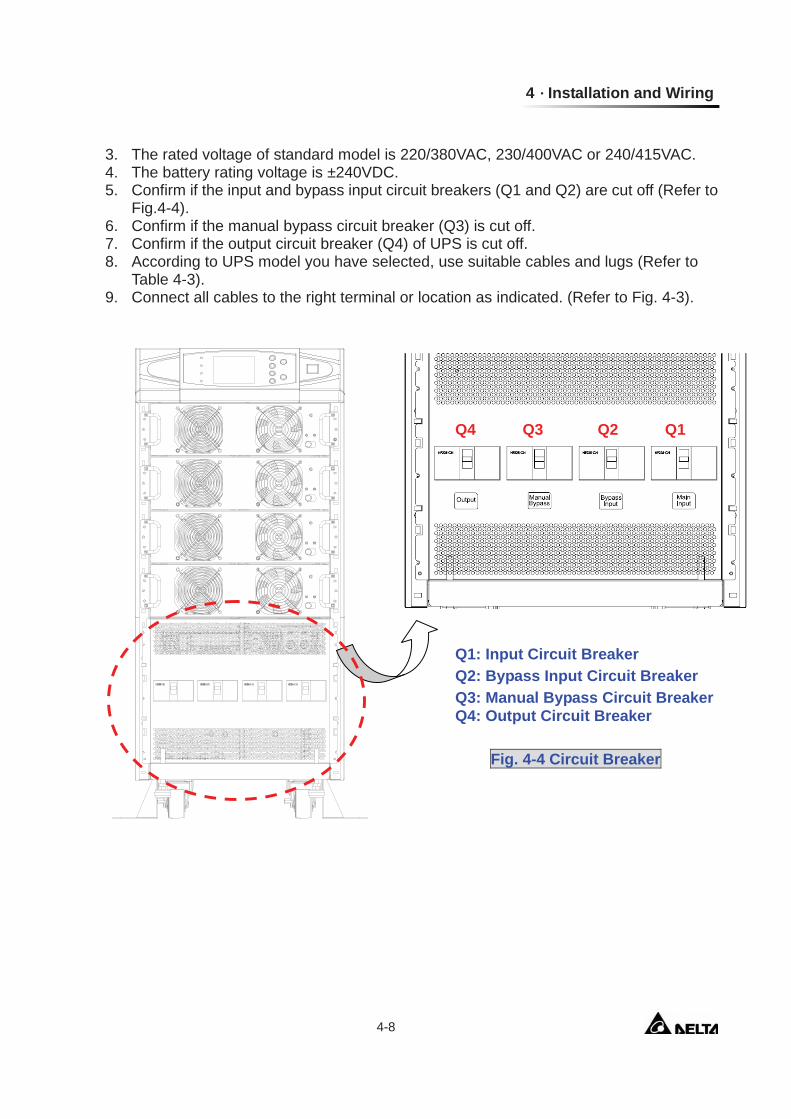
3. The rated voltage of standard model is 220/380VAC, 230/400VAC or 240/415VAC. 4. The battery rating voltage is ±240VDC. 5. Confirm if the input and bypass input circuit breakers (Q1 and Q2) are cut off (Refer to
Fig.4-4). 6. Confirm if the manual bypass circuit breaker (Q3) is cut off. 7. Confirm if the output circuit breaker (Q4) of UPS is cut off. 8. According to UPS model you have selected, use suitable cables and lugs (Refer to
Table 4-3). 9. Connect all cables to the right terminal or location as indicated. (Refer to Fig. 4-3).
Q4 Q3 Q2 Q1
Q1: Input Circuit Breaker Q2: Bypass Input Circuit Breaker Q3: Manual Bypass Circuit Breaker Q4: Output Circuit Breaker
Fig. 4-4 Circuit Breaker
Modulon NH Plus Series 4-9
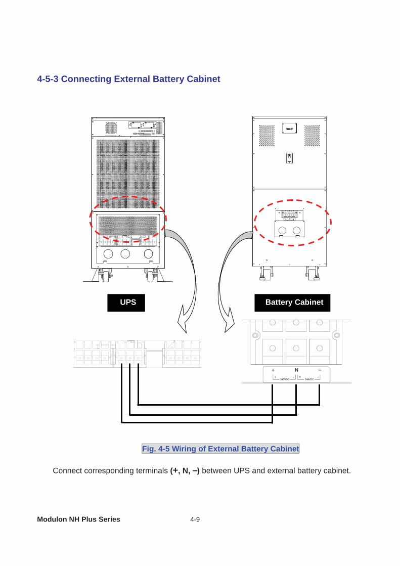
4-5-3 Connecting External Battery Cabinet
Connect corresponding terminals (+, N, –) between UPS and external battery cabinet.
Fig. 4-5 Wiring of External Battery Cabinet
UPS Battery Cabinet
4 Installation and Wiring
4-10
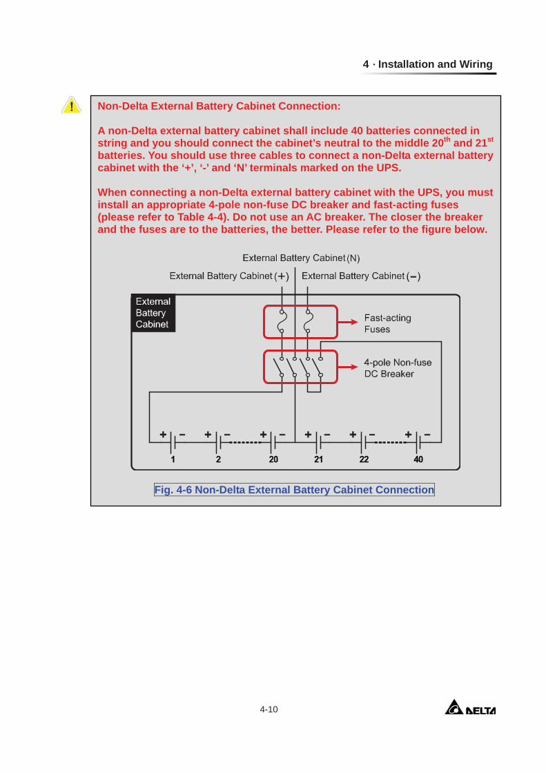
Non-Delta External Battery Cabinet Connection: A non-Delta external battery cabinet shall include 40 batteries connected in string and you should connect the cabinet’s neutral to the middle 20th and 21st batteries. You should use three cables to connect a non-Delta external battery cabinet with the ‘+’, ‘-’ and ‘N’ terminals marked on the UPS. When connecting a non-Delta external battery cabinet with the UPS, you must install an appropriate 4-pole non-fuse DC breaker and fast-acting fuses (please refer to Table 4-4). Do not use an AC breaker. The closer the breaker and the fuses are to the batteries, the better. Please refer to the figure below.
Fig. 4-6 Non-Delta External Battery Cabinet Connection
Modulon NH Plus Series 4-11
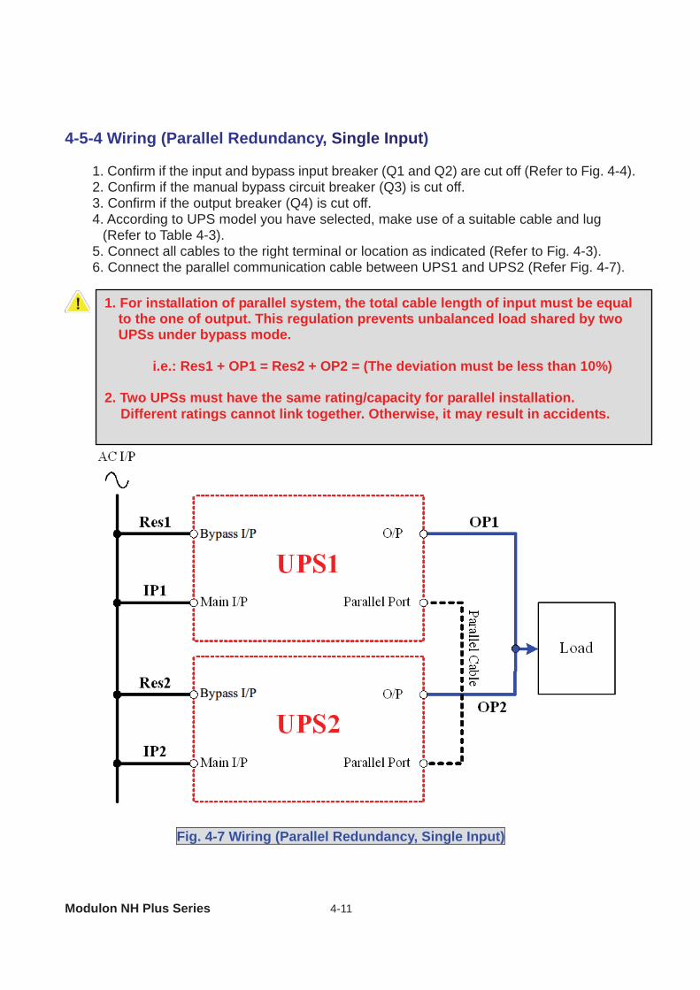
4-5-4 Wiring (Parallel Redundancy, Single Input)
1. Confirm if the input and bypass input breaker (Q1 and Q2) are cut off (Refer to Fig. 4-4). 2. Confirm if the manual bypass circuit breaker (Q3) is cut off. 3. Confirm if the output breaker (Q4) is cut off. 4. According to UPS model you have selected, make use of a suitable cable and lug
(Refer to Table 4-3). 5. Connect all cables to the right terminal or location as indicated (Refer to Fig. 4-3). 6. Connect the parallel communication cable between UPS1 and UPS2 (Refer Fig. 4-7).
Fig. 4-7 Wiring (Parallel Redundancy, Single Input)
1. For installation of parallel system, the total cable length of input must be equal to the one of output. This regulation prevents unbalanced load shared by two UPSs under bypass mode.
i.e.: Res1 + OP1 = Res2 + OP2 = (The deviation must be less than 10%) 2. Two UPSs must have the same rating/capacity for parallel installation.
Different ratings cannot link together. Otherwise, it may result in accidents.
4 Installation and Wiring
4-12
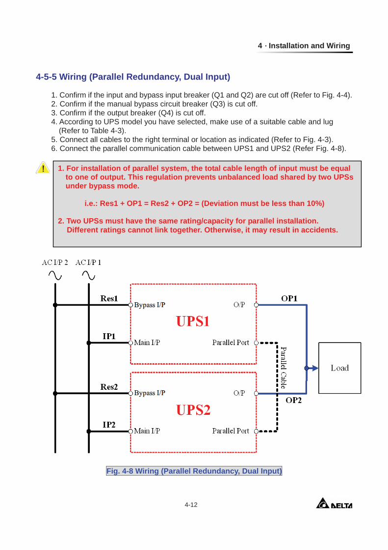
4-5-5 Wiring (Parallel Redundancy, Dual Input)
1. Confirm if the input and bypass input breaker (Q1 and Q2) are cut off (Refer to Fig. 4-4). 2. Confirm if the manual bypass circuit breaker (Q3) is cut off. 3. Confirm if the output breaker (Q4) is cut off. 4. According to UPS model you have selected, make use of a suitable cable and lug
(Refer to Table 4-3). 5. Connect all cables to the right terminal or location as indicated (Refer to Fig. 4-3). 6. Connect the parallel communication cable between UPS1 and UPS2 (Refer Fig. 4-8).
Fig. 4-8 Wiring (Parallel Redundancy, Dual Input)
1. For installation of parallel system, the total cable length of input must be equal to one of output. This regulation prevents unbalanced load shared by two UPSs under bypass mode.
i.e.: Res1 + OP1 = Res2 + OP2 = (Deviation must be less than 10%) 2. Two UPSs must have the same rating/capacity for parallel installation.
Different ratings cannot link together. Otherwise, it may result in accidents.
Modulon NH Plus Series 5-1
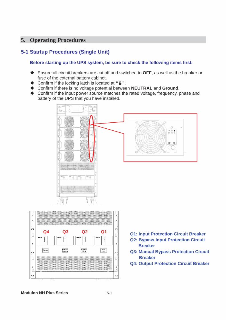
5. Operating Procedures 5-1 Startup Procedures (Single Unit)
Before starting up the UPS system, be sure to check the following items first.
Ensure all circuit breakers are cut off and switched to OFF, as well as the breaker or fuse of the external battery cabinet.
Confirm if the locking latch is located at “ ”. Confirm if there is no voltage potential between NEUTRAL and Ground. Confirm if the input power source matches the rated voltage, frequency, phase and
battery of the UPS that you have installed.
Q4 Q3 Q2 Q1 Q1: Input Protection Circuit Breaker Q2: Bypass Input Protection Circuit
Breaker Q3: Manual Bypass Protection Circuit
Breaker Q4: Output Protection Circuit Breaker
Fail OnOff
5 Operating Procedures
5-2
If the conditions mentioned above are satisfied, follow the steps below to start up. 1. If there is an external battery cabinet, switch the circuit breaker of battery cabinet to
ON and confirm if manual bypass protection circuit breaker Q3 is cut off and switched to OFF.
2. Switch on Q2 and Q4. The LCD monitor will start displaying. After initialization, the LCD screen will show ”ON AUTO BYPASS”. In the meantime, the UPS output is supplied by the bypass source and the LED indicator of ”BYPASS” will also light on.
3. Switch Q1 to ON. If the input power source is within tolerance range, the UPS power module will be ready to start up.
4. Press the “I” button for 3 seconds until you hear a “beep” and then release the button. At this time, the inverter will start the synchronization with bypass source. The UPS will automatically transfer from bypass mode to inverter mode, and the output will be supplied by the inverter. The ”BYPASS” LED indicator lights off and the ”NORMAL” LED indicator lights on.
5-2 Battery Startup Procedures (Single Unit)
1. Switch the circuit breaker of external battery cabinet to ON and confirm if Q3 is cut off
and switched to OFF. 2. Press the “I” button for 3 seconds until you hear a “beep” and then release the button. 3. The UPS will start up by DC-bus soft start. The inverter will be activated by adopting
the default frequency value. 4. When the inverter startup is completed, the UPS will transfer to Inverter mode and
the ”BATTERY” LED indicator lights on.
5-3 Shutdown Procedures (Single Unit)
This operating procedure can cut off all the power supply. Be sure to confirm if the loads are turned off first! Refer to following steps.
1. Press the “O” button for 3 seconds until you hear a “beep” and then release button. The LCD screen will show “SHUTDOWN UPS?”, then selected “YES” and press “ ” to confirm. If the UPS is originally in - Normal mode: The UPS will transfer to bypass mode. The LCD screen will
show ”ON AUTO BYPASS”. - Battery mode: The UPS will shut down the inverter and cut off the output power. 2. Switch off Q1. 3. Switch off Q2. 4. Confirm if the UPS is turned off and all the circuits are off. 5. If there is an external battery cabinet, switch off the circuit breaker of battery cabinet. 6. Switch off Q4.
Modulon NH Plus Series 5-3
5-4 Manual Bypass Startup Procedures (Single Unit)
If the UPS is in normal mode, press the “O” button for 3 seconds until you hear a “beep” and then release the button. The LCD screen will show “SHUTDOWN UPS?”, then select “YES” and press “ ” to confirm. The UPS will automatically transfer to bypass mode.
1. Confirm if the UPS is in bypass mode. 2. Switch on “Q3”. 3. Switch off “Q4”.
1. Only for maintenance purpose, you can manually turn on the bypass switch “Q3”. If you switch on Q3 under normal condition, the inverter will shut down and the output will be supplied by manual bypass source.
2. Manual bypass mode ensures that the UPS supplies the loads from manual
bypass source. The service personnel can perform maintenance process under this mode without interrupting the loads. At this moment, the UPS is still supplied by input power source. If the service personnel want to replace any circuit board or component, please power off the UPS (Refer to 5-3) first.
5 Operating Procedures
5-4
5-5 Startup Procedures (Parallel Redundancy)
Before starting up the UPS system, be sure to check the following items first.
All circuit breakers are cut off and switched to OFF, as well as the breaker or fuse of the external battery cabinet.
Confirm if the locking latch is located at “ ”. Confirm if there is no voltage potential between NEUTRAL and Ground. Confirm if the input power source matches the rated voltage, frequency, phase and
battery of the UPS that you have installed.
Startup procedure:
If the conditions mentioned above are satisfied, follow the steps below to start up.
1. Connect two UPSs by using the parallel communication cable. Ensure the connector is fastened to the DB9 port.
2. Switch the breaker of external battery cabinet to ON. 3. Switch on bypass input protection circuit breaker “Q2” of each UPS. The LCD screen
will show ”ON AUTO BYPASS”. 4. Switch on “Q1” of each UPS. 5. Press the “I” button for 3 seconds until you hear a “beep” and then release the button.
The inverter will be activated and synchronize with bypass source.
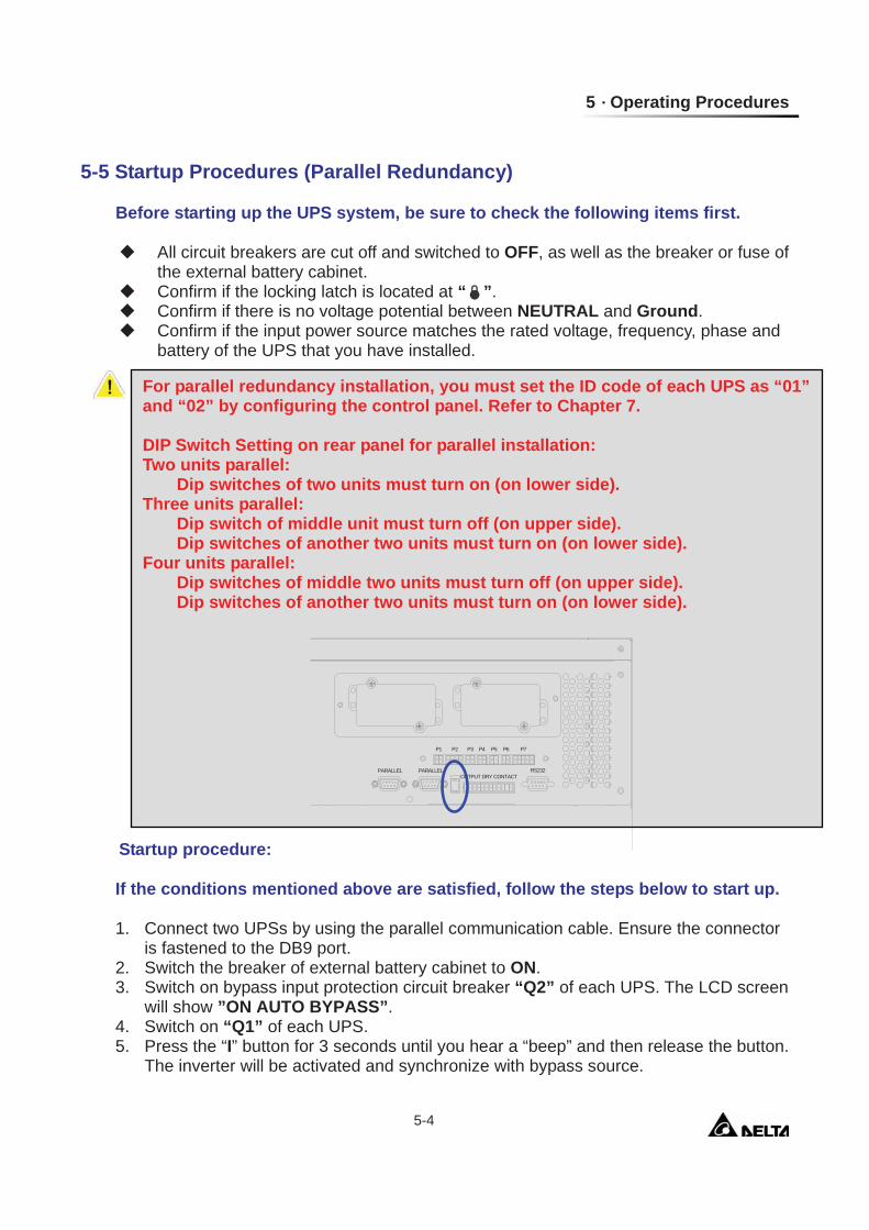
For parallel redundancy installation, you must set the ID code of each UPS as “01” and “02” by configuring the control panel. Refer to Chapter 7. DIP Switch Setting on rear panel for parallel installation: Two units parallel: Dip switches of two units must turn on (on lower side). Three units parallel:
Dip switch of middle unit must turn off (on upper side). Dip switches of another two units must turn on (on lower side).
Four units parallel: Dip switches of middle two units must turn off (on upper side).
Dip switches of another two units must turn on (on lower side).
P1 P2 P3 P4 P5 P6 P7
RS232OUTPUT DRY CONTACT
PARALLELPARALLEL
Modulon NH Plus Series 5-5
6. Repeat Step 5 to start up another UPS. When the inverter voltage of both UPSs activates normally, both UPSs will transfer to normal mode at the same time.
7. Check the output voltage deviation per each phase of each UPS (must be less than 5V). If it is normal, switch on “Q4” of each UPS.
5-6 Shutdown Procedures (Parallel Redundancy)
If you need to shut down one of the paralleled UPSs: 1. Press the “O” button on the UPS that you want to shut down for 3 seconds until you
hear a “beep” and then release the button. The LCD screen will show “SHUTDOWN UPS?”, then select “YES” and press “ ” to confirm. - If the other UPS can take over the total loads, then the turn-off one will shutdown
inverter. The LCD screen shows ”LOAD NOT POWERED” for the turn-off one. The working UPS shows ”ONLINE MODE”.
- If the total loads are greater than one UPS can take over, then both UPSs will shut down the inverter and transfer to bypass mode. Both UPSs show ”ON AUTO BYPASS”.
2. Switch off “Q1” and “Q4” of the UPS that you want to shut down. 3. Switch off “Q2” of the UPS that you want to shut down. 4. When all the power modules complete the discharging procedures, the LCD screen
will be off. 5. Switch off the battery circuit breaker of the external battery cabinet.
5 Operating Procedures
5-6
5-7 Manual Bypass Startup Procedures (Parallel Redundancy)
5-7-1 Online Mode Transfers to Manual Bypass Mode 1. Press the “O” button of the UPS that you want to shut down for 3 seconds until you
hear a “beep” and then release the button. The LCD screen will show “SHUTDOWN UPS?”, then select “YES” and press “ ” to confirm. - If the other UPS can take over the total loads, then the turned-off one will shut down
the inverter. The LCD screen shows ”LOAD NOT POWERED” for the turned-off one. The working UPS shows ”ONLINE MODE”.
- If the total loads are greater than one UPS can take over, then both UPSs will shut down the inverter and transfer to bypass mode. Both UPSs show ”ON AUTO BYPASS”.
2. Repeat Step 1 for another UPS. 3. Switch off “Q1” of both UPSs. 4. Confirm if both UPSs are completely shut down. 5. Switch on “Q3” of both UPSs. Bypass power source supplies the loads. The LCD
screen shows ”ON MANUAL BYPASS”. 6. Switch off ”Q4” and ”Q2” of both UPSs. The LCD screen will be off. 7. Switch off battery circuit breaker of the external battery cabinet. 8. In this mode, only ”Q4” and terminal block has hazard voltage. Service personnel can
perform maintenance work.
5-7-2 Transferring from Manual Bypass Mode to Online Mode
1. Switch on the battery circuit breaker of external battery cabinet. 2. Switch on ”Q2” and ”Q4” of both UPSs.
Switch off ”Q3” of both UPSs. The LCD screens of both UPSs show ”ON AUTO BYPASS”.
3. Switch on ”Q1” of both UPSs. 4. Press the “I” button for 3 seconds until you hear a “beep” and then release the button. 5. Repeat Step 5 to start up another UPS. When the inverter voltage of both UPSs
activates normally, both UPSs will transfer to normal mode at the same time.
Only for maintenance purpose, you can manually turn on the bypass switch. If you switch on Q3 under normal status, the inverter will shut down and the output will be supplied by manual bypass source.
Modulon NH Plus Series 6-1
6. Power Module Replacement 6-1 Status LED Indicators for Power Module
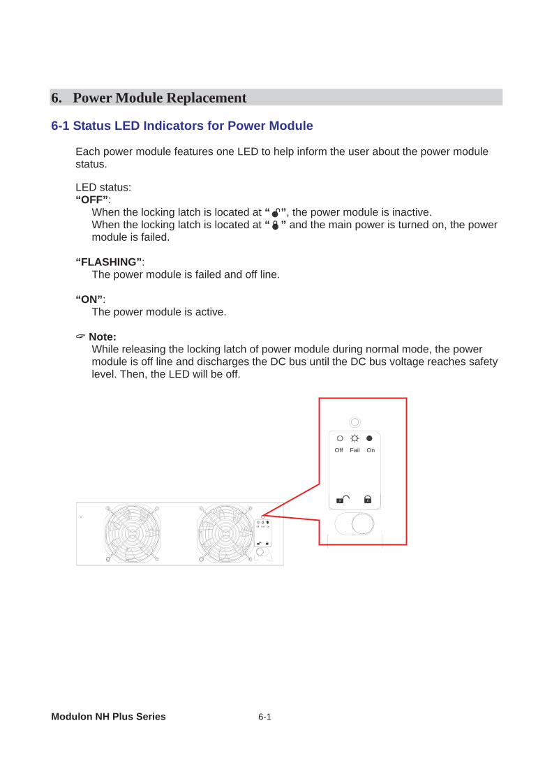
Each power module features one LED to help inform the user about the power module status.
LED status: “OFF”:
When the locking latch is located at “ ”, the power module is inactive. When the locking latch is located at “ ” and the main power is turned on, the power module is failed.
“FLASHING”:
The power module is failed and off line. “ON”:
The power module is active.
Note: While releasing the locking latch of power module during normal mode, the power module is off line and discharges the DC bus until the DC bus voltage reaches safety level. Then, the LED will be off.
Fail OnOff
Fail OnOff
6 Power Module Replacement
6-2
6-2 Power Module Replacement
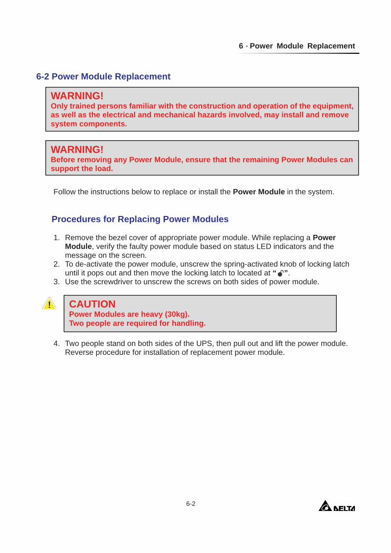
Follow the instructions below to replace or install the Power Module in the system.
Procedures for Replacing Power Modules
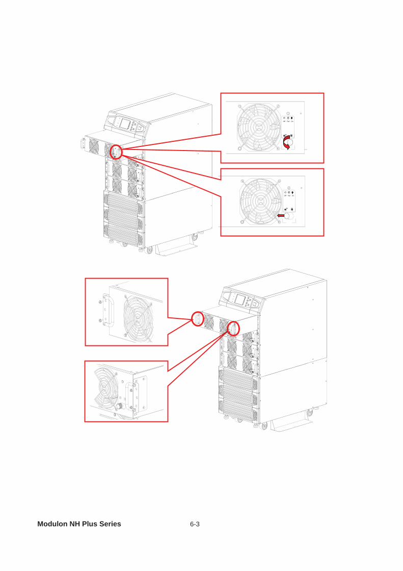
1. Remove the bezel cover of appropriate power module. While replacing a Power Module, verify the faulty power module based on status LED indicators and the message on the screen.
2. To de-activate the power module, unscrew the spring-activated knob of locking latch until it pops out and then move the locking latch to located at “ ”.
3. Use the screwdriver to unscrew the screws on both sides of power module. 4. Two people stand on both sides of the UPS, then pull out and lift the power module.
Reverse procedure for installation of replacement power module.
WARNING! Only trained persons familiar with the construction and operation of the equipment, as well as the electrical and mechanical hazards involved, may install and remove system components.
WARNING! Before removing any Power Module, ensure that the remaining Power Modules can support the load.
CAUTION Power Modules are heavy (30kg). Two people are required for handling.
Modulon NH Plus Series 6-3
Fail OnOff
Fail OnOff
7 Display and Configuration
7-1
7. Display and Configuration 7-1. Control Panel
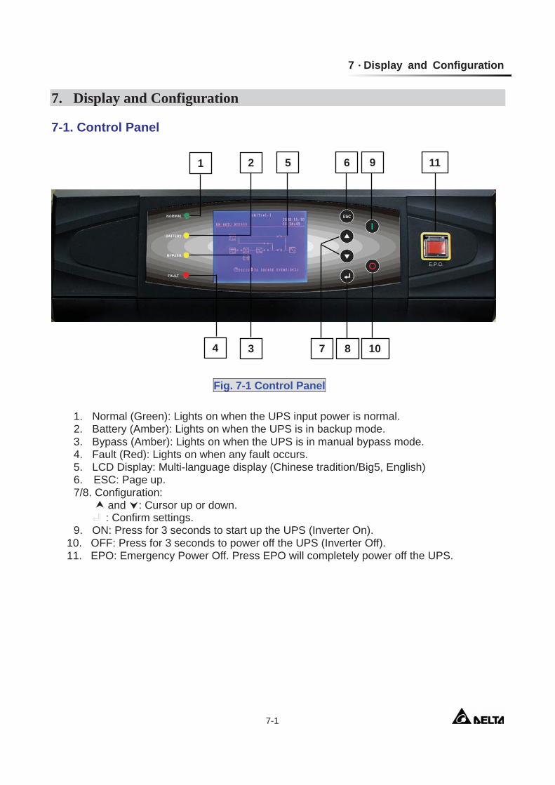
1. Normal (Green): Lights on when the UPS input power is normal. 2. Battery (Amber): Lights on when the UPS is in backup mode. 3. Bypass (Amber): Lights on when the UPS is in manual bypass mode. 4. Fault (Red): Lights on when any fault occurs. 5. LCD Display: Multi-language display (Chinese tradition/Big5, English) 6. ESC: Page up. 7/8. Configuration: and : Cursor up or down. : Confirm settings. 9. ON: Press for 3 seconds to start up the UPS (Inverter On).
10. OFF: Press for 3 seconds to power off the UPS (Inverter Off). 11. EPO: Emergency Power Off. Press EPO will completely power off the UPS.
Fig. 7-1 Control Panel
1 2 5 6 9 11
4 3 7 8 10
Modulon NH Plus Series 7-2
7-2 LCD Display NH Plus Series UPS features a user-friendly LCD screen to show messages.
7-2-1 LCD Display Hierarchy
Fig. 7-2 LCD Display Hierarchy
7 Display and Configuration
7-3
7-3 Default Screen
After the UPS starts up and completes the self test, the screen will show as below.
1. When any event occurs, you will see the sign “!” flashes. You can press “ ” to see the details. For example:
Press “ ” again will go to the next message. If there is no further message, the screen will return to the default screen. 2. Press “ESC” at any time will return to the default screen.
P 2 0 0 8 - 1 0 - 0 2RO T E C T E DL OAD UNUN I T : # 1 . 1
1 1 : 5 9 : 5 9BY P A S SON AU T O
RP T O B ROWS E E V E N T ( 0 0 4 )SE S!
BYPA.
MAINS
Modulon NH Plus Series 7-4
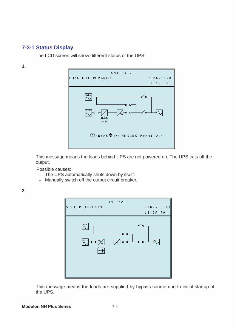
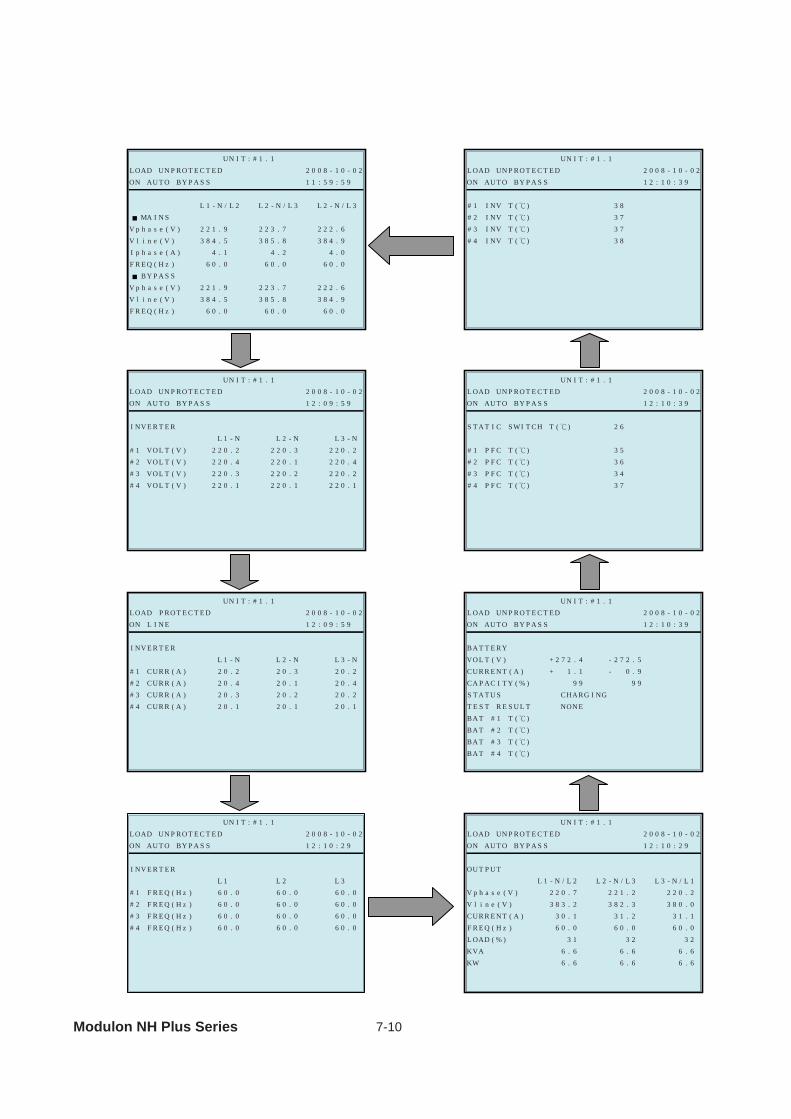
7-3-1 Status Display
The LCD screen will show different status of the UPS. 1.
This message means the loads behind UPS are not powered on. The UPS cuts off the output. Possible causes:
- The UPS automatically shuts down by itself. - Manually switch off the output circuit breaker.
2.
This message means the loads are supplied by bypass source due to initial startup of the UPS.
7 Display and Configuration
7-5
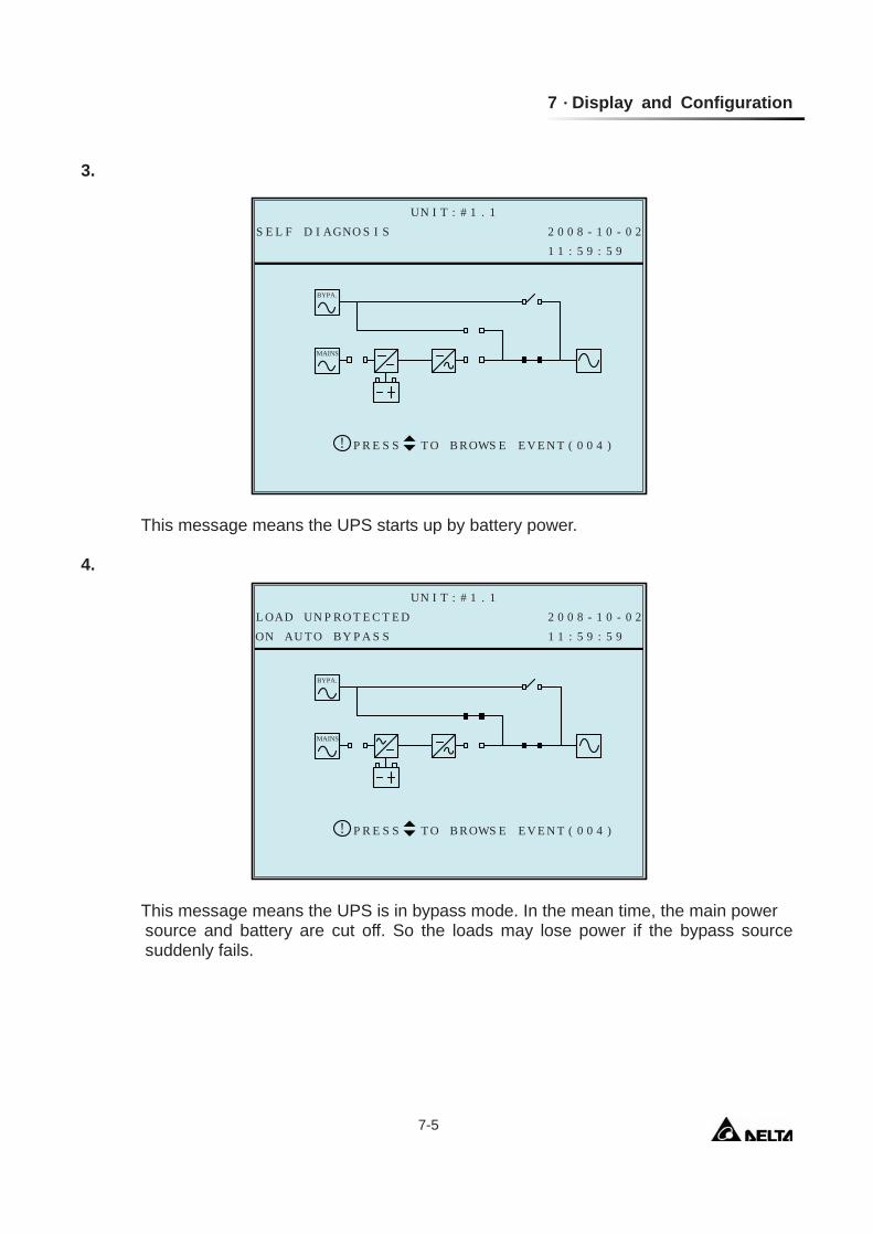
3.
This message means the UPS starts up by battery power. 4.
This message means the UPS is in bypass mode. In the mean time, the main power
source and battery are cut off. So the loads may lose power if the bypass source suddenly fails.
A 2 0 0 8 - 1 0 - 0 2GNO S I SS E L F D IUN I T : # 1 . 1
1 1 : 5 9 : 5 9
RP T O B ROWS E E V E N T ( 0 0 4 )SE S!
BYPA.
MAINS
P 2 0 0 8 - 1 0 - 0 2RO T E C T E DL OAD UNUN I T : # 1 . 1
1 1 : 5 9 : 5 9BY P A S SON AU T O
RP T O B ROWS E E V E N T ( 0 0 4 )SE S!
BYPA.
MAINS
Modulon NH Plus Series 7-6
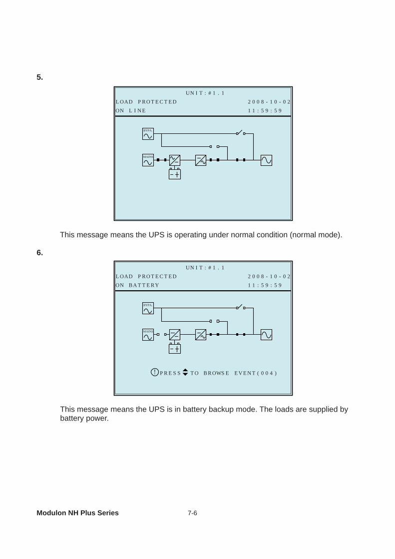
5.
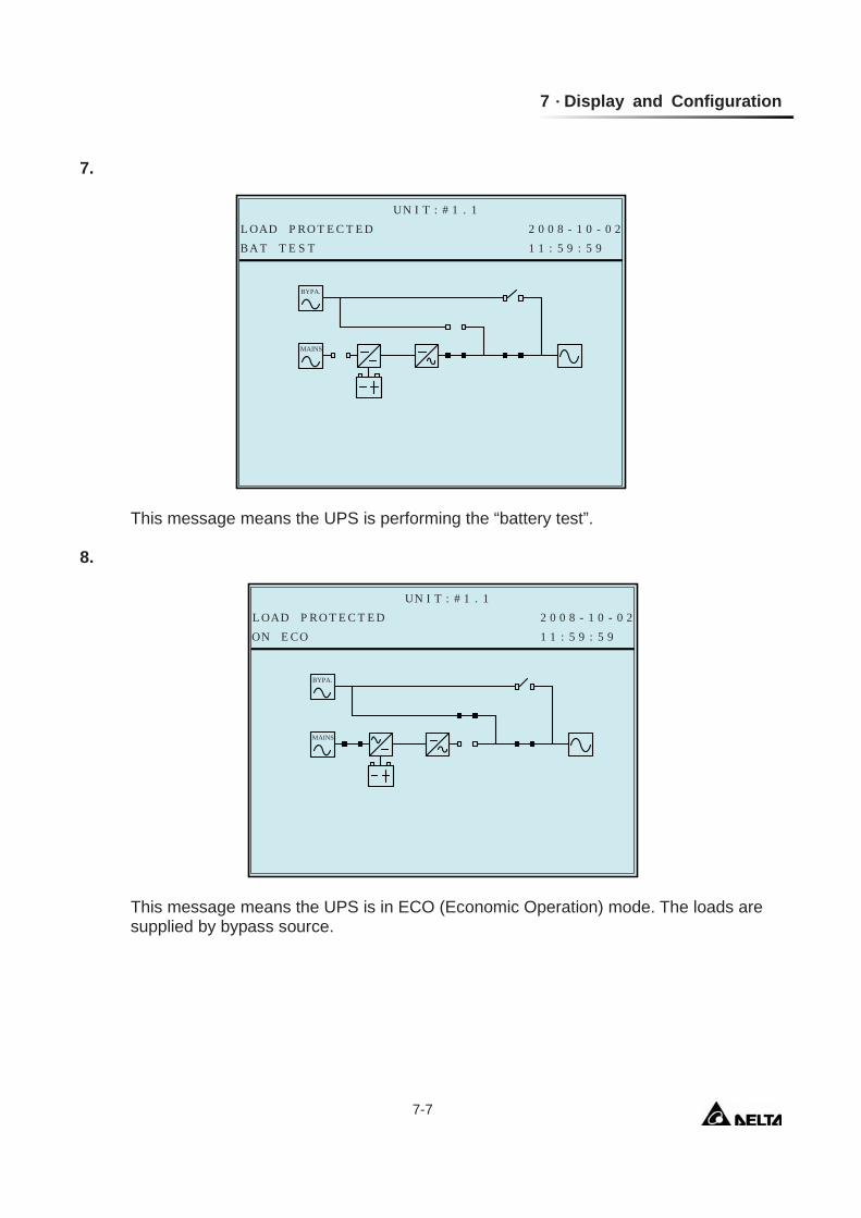
This message means the UPS is operating under normal condition (normal mode). 6.
This message means the UPS is in battery backup mode. The loads are supplied by
battery power.
2 0 0 8 - 1 0 - 0 2L OADUN I T : # 1 . 1
1 1 : 5 9 : 5 9ON L I N EP RO T E C T E D
BYPA.
MAINS
2 0 0 8 - 1 0 - 0 2L OADUN I T : # 1 . 1
1 1 : 5 9 : 5 9RYON BA T T EP RO T E C T E D
RP T O B ROWS E E V E N T ( 0 0 4 )SE S!
BYPA.
MAINS
7 Display and Configuration
7-7
7.
This message means the UPS is performing the “battery test”. 8.
This message means the UPS is in ECO (Economic Operation) mode. The loads are
supplied by bypass source.
2 0 0 8 - 1 0 - 0 2L OADUN I T : # 1 . 1
1 1 : 5 9 : 5 9BA T T E S TP RO T E C T E D
BYPA.
MAINS
2 0 0 8 - 1 0 - 0 2L OADUN I T : # 1 . 1
1 1 : 5 9 : 5 9ON E COP RO T E C T E D
BYPA.
MAINS
Modulon NH Plus Series 7-8
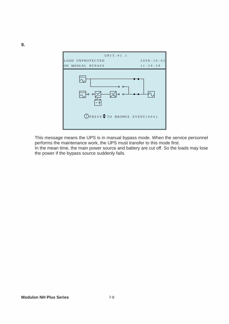
9.
This message means the UPS is in manual bypass mode. When the service personnel
performs the maintenance work, the UPS must transfer to this mode first. In the mean time, the main power source and battery are cut off. So the loads may lose the power if the bypass source suddenly fails.
2 0 0 8 - 1 0 - 0 2L OAD UNUN I T : # 1 . 1
1 1 : 5 9 : 5 9L BY P A S SON MANUA
RP T O B ROWS E E V E N T ( 0 0 4 )SE S!
BYPA.
MAINS
P RO T E C T E D
7 Display and Configuration
7-9
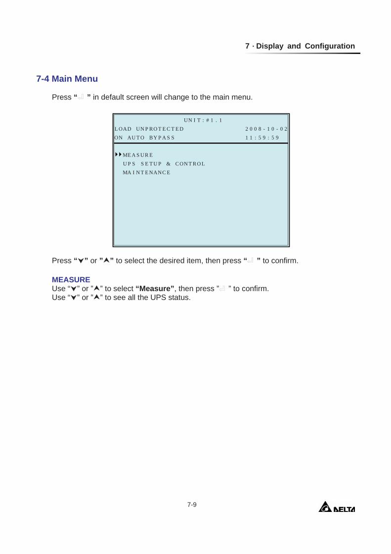
7-4 Main Menu
Press “ ” in default screen will change to the main menu.
Press “ ” or ” ” to select the desired item, then press “ ” to confirm.
MEASURE Use “ ” or ” ” to select “Measure”, then press ” ” to confirm. Use “ ” or ” ” to see all the UPS status.
UR
P
MA I N
EME A SU P S
2 0 0 8 - 1 0 - 0 2RO T E C T E DL OAD UNUN I T : # 1 . 1
1 1 : 5 9 : 5 9BY P A S SON AU T O
N T RO LT U P & COS ENANC ET E
Modulon NH Plus Series 7-10
N
P
V l i n e (V p h a s e
I p h a s e
/ L 2L 1 -MA I N
BY P A S SF R E Q ( H
2 0 0 8 - 1 0 - 0 2RO T E C T E DL OAD UNUN I T : # 1 . 1
1 1 : 5 9 : 5 9BY P A S SON AU T O
S9) 2 2 1 .( V53 8 4 .V )1) 4 .( A06 0 .z )
V l i n e (V p h a s e )( V
V )F R E Q ( H z )
N / L 3L 2 - N / L 3L 2 -
72 2 3 .83 8 5 .24 .06 0 .
62 2 2 .93 8 4 .04 .06 0 .
92 2 1 .53 8 4 .06 0 .
72 2 3 .83 8 5 .06 0 .
62 2 2 .93 8 4 .06 0 .
0
E R
P
. 4# 2 VO L
. 2# 1 VO L
. 2
I NV E R T
. 1
2 0 0 8 - 1 0 - 0 2RO T E C T E DL OAD UNUN I T : # 1 . 1
1 2 : 0 9 : 5 9BY P A S SON AU T O
0 . 2V ) 2 2T (0 . 4V ) 2 2T (0 . 32 20 . 12 2
02 22 2
02 202 2
# 3 VO L V )T (# 4 VO L V )T (
0 . 1. 3
. 2
. 1
02 22 2
02 202 2
L 1 - N NL 2 - L 3 - N
0
E R
P
. 4# 2 CUR
. 2# 1 CUR
. 2
I NV E R T
. 1
2 0 0 8 - 1 0 - 0 2RO T E C T E DL OADUN I T : # 1 . 1
1 2 : 0 9 : 5 9ON L I N E
0 . 2A ) 2R (0 . 4A ) 2R (0 . 320 . 12
022
0202
# 3 CUR A )R (# 4 CUR A )R (
0 . 1. 3
. 2
. 1
022
0202
L 1 - N NL 2 - L 3 - N
0
E R
P
. 0# 2
. 0# 1 F R E
. 0
I NV E R T
. 0
2 0 0 8 - 1 0 - 0 2RO T E C T E DL OAD UNUN I T : # 1 . 1
1 2 : 1 0 : 2 9BY P A S SON AU T O
0 . 0H z ) 6Q (0 . 060 . 060 . 06
066
0606
# 3# 4
0 . 0. 0
. 0
. 0
066
0606
L 1 L 2 L 3
F R E H z )Q (F R E H z )Q (F R E H z )Q (
0
P
. 0V l i
. 2V p h a s e
. 1
OU T P U T
. 6
3 1 3 2. 0
. 6
2 0 0 8 - 1 0 - 0 2RO T E C T E DL OAD UNUN I T : # 1 . 1
1 2 : 1 0 : 2 9BY P A S SON AU T O
L 1 -0 . 7) 2 2( V3 . 23 80 . 130 . 06
KW
02 23 8
1306
66
CURF R EL OAKVA
2 . 3. 2
. 2
. 0
12 23 8
1306
N / L 2
n e ( V )R E N A )T (Q ( H z )D ( % )
L 2 - N / L 3 L 3 - N / L 1
. 66
. 66
3 2. 66. 66
RY
P
CA PCUR R E N
BA T T EVO L T ( V
2 0 0 8 - 1 0 - 0 2RO T E C T E DL OAD UNUN I T : # 1 . 1
1 2 : 1 0 : 3 9BY P A S SON AU T O
4 - 5+)1 . 1 9A ) +T (
9 9 9CHARG INON E
NGS T AT E SBA T
90 .-
2 7 2 . .2 7 2
AC I ( % )T YT U ST R U L TE S
# 1 ( )TBA T # 2 ( )TBA T # 3 ( )TBA T # 4 ( )T
C S
P
# 1 P F C
WI T CHS T A T I
2 0 0 8 - 1 0 - 0 2RO T E C T E DL OAD UNUN I T : # 1 . 1
1 2 : 1 0 : 3 9BY P A S SON AU T O
2 6
53
( )T
( )T# 2 P F C ( )T# 3 P F C ( )T# 4 P F C ( )T
634373
P 2 0 0 8 - 1 0 - 0 2RO T E C T E DL OAD UNUN I T : # 1 . 1
1 2 : 1 0 : 3 9BY P A S SON AU T O
3 8# 1 I NV ( )T# 2 I NV ( )T# 3 I NV ( )T# 4 I NV ( )T
3 73 73 8
7 Display and Configuration
7-11
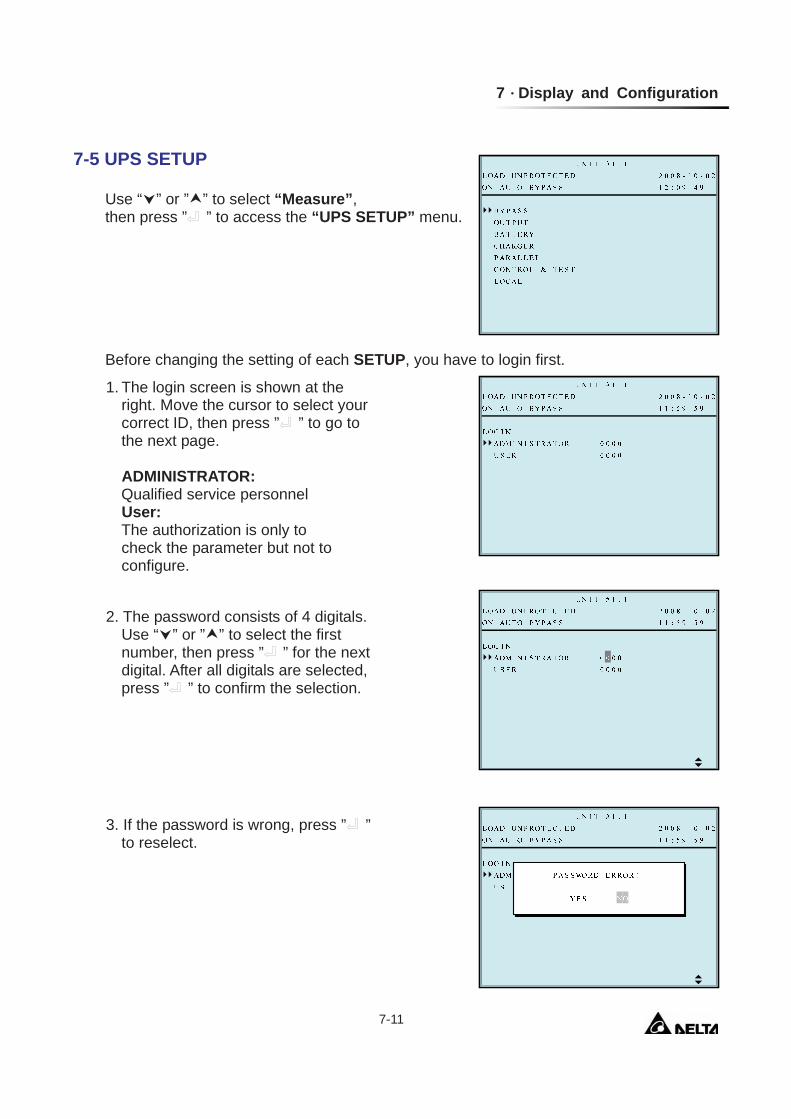
7-5 UPS SETUP
Use “ ” or ” ” to select “Measure”, then press ” ” to access the “UPS SETUP” menu. Before changing the setting of each SETUP, you have to login first.
1. The login screen is shown at the right. Move the cursor to select your correct ID, then press ” ” to go to the next page.
ADMINISTRATOR:
Qualified service personnel User:
The authorization is only to check the parameter but not to configure.
2. The password consists of 4 digitals. Use “ ” or ” ” to select the first number, then press ” ” for the next digital. After all digitals are selected, press ” ” to confirm the selection.
3. If the password is wrong, press ” ” to reselect.
Modulon NH Plus Series 7-12
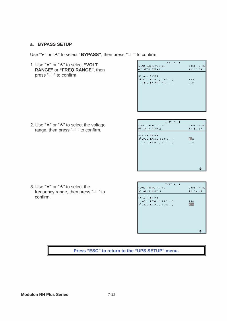
a. BYPASS SETUP
Use “ ” or ” ” to select “BYPASS”, then press ” ” to confirm.
1. Use “ ” or ” ” to select “VOLT RANGE” or “FREQ RANGE", then press ” ” to confirm.
2. Use “ ” or ” ” to select the voltage range, then press ” ” to confirm.
3. Use “ ” or ” ” to select the frequency range, then press ” ” to confirm.
Press “ESC” to return to the “UPS SETUP” menu.
7 Display and Configuration
7-13
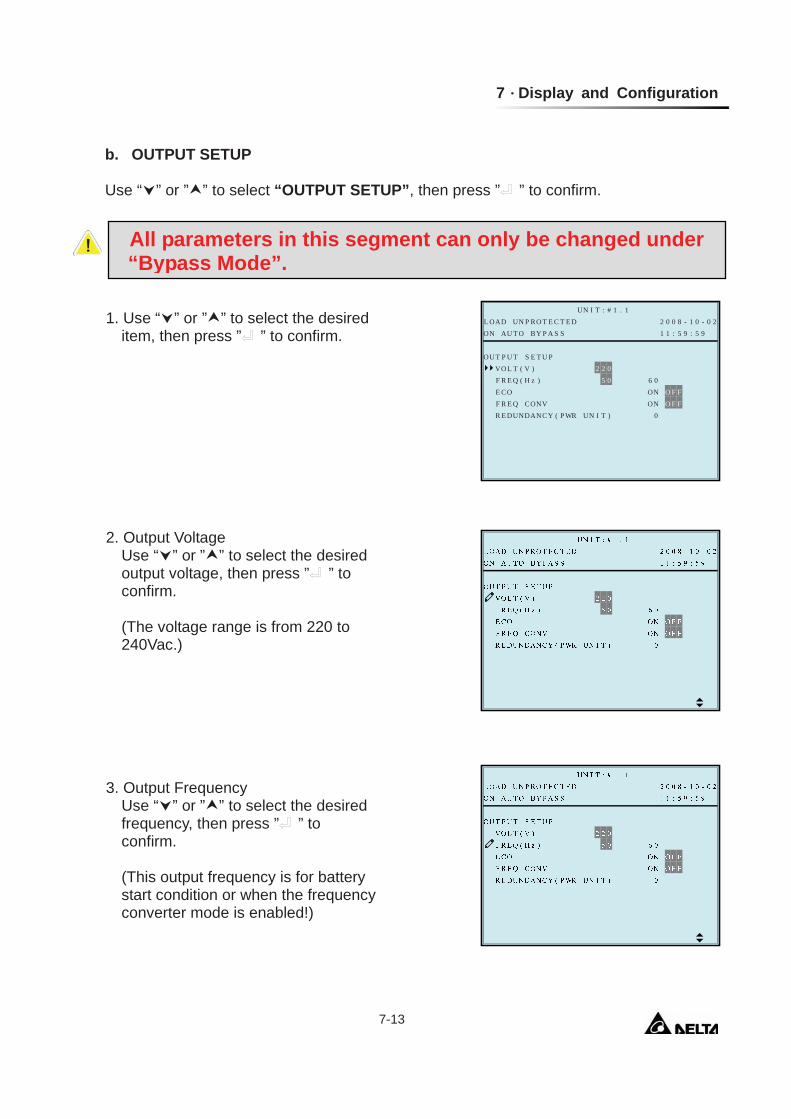
b. OUTPUT SETUP Use “ ” or ” ” to select “OUTPUT SETUP”, then press ” ” to confirm.
1. Use “ ” or ” ” to select the desired item, then press ” ” to confirm.
2. Output Voltage Use “ ” or ” ” to select the desired output voltage, then press ” ” to confirm. (The voltage range is from 220 to 240Vac.)
3. Output Frequency Use “ ” or ” ” to select the desired frequency, then press ” ” to confirm.
(This output frequency is for battery start condition or when the frequency converter mode is enabled!)
All parameters in this segment can only be changed under “Bypass Mode”.
S
P
F R E Q
E T U PVO L T
2 0 0 8 - 1 0 - 0 2RO T E C T E DL OAD UNUN I T : # 1 . 1
1 1 : 5 9 : 5 9BY P A S SON AU T O
2 2 00 6 0(
ON O F F
UN I T ) 0
U TOU T P
z )H 5
VNOF R E Q CE CO
ANCY ( P WRR E DUND
V )(
ON O F F

Modulon NH Plus Series 7-14
Press “ESC” to return to the “UPS SETUP” menu.
5. Frequency Converter Mode Use “ ” or ” ” to select the desired mode, then press ” ” to confirm.
4. ECO mode Use “ ” or ” ” to select the desired mode, then press ” ” to confirm.
6. Redundancy Use “ ” or ” ” to select the desired number for redundancy, then press ” ” to confirm.
7 Display and Configuration
7-15
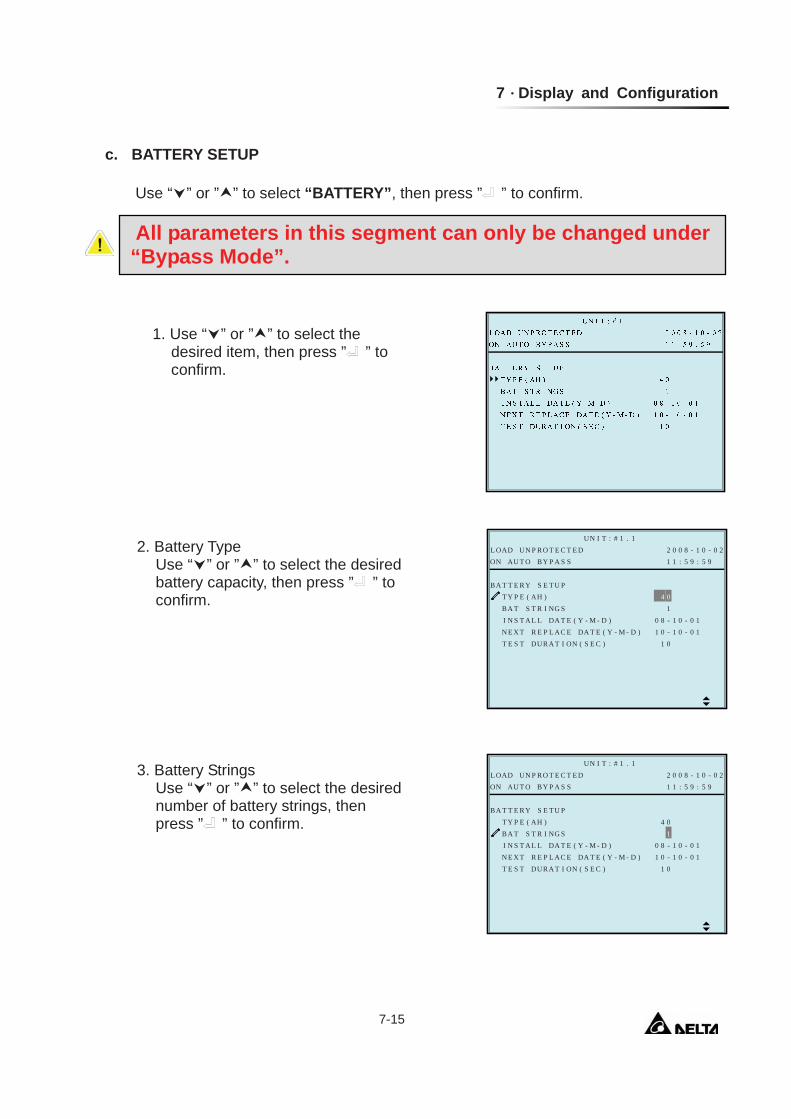
c. BATTERY SETUP
Use “ ” or ” ” to select “BATTERY”, then press ” ” to confirm.
1. Use “ ” or ” ” to select the desired item, then press ” ” to confirm.
2. Battery Type Use “ ” or ” ” to select the desired battery capacity, then press ” ” to confirm.
All parameters in this segment can only be changed under “Bypass Mode”.
L
R
P
BA T
YT Y P E
2 0 0 8 - 1 0 - 0 2RO T E C T E DL OAD UNUN I T : # 1 . 1
1 1 : 5 9 : 5 9BY P A S SON AU T O
4 0)1SS
- M - D ) 0 8 - 1 0 - 0 11 0 - 1 0 - 0 1
1 0
EBA T T
R I NGT
APE C EN E X T RL DA T E ( YI N S T A L
AH(S E T U P
- M - D )DA T E ( YS E C )TAUR (NI OT E S T D
L
R
P
BA T
YT Y P E
2 0 0 8 - 1 0 - 0 2RO T E C T E DL OAD UNUN I T : # 1 . 1
1 1 : 5 9 : 5 9BY P A S SON AU T O
4 0)1SS
- M - D ) 0 8 - 1 0 - 0 11 0 - 1 0 - 0 1
1 0
EBA T T
R I NGT
APE C EN E X T RL DA T E ( YI N S T A L
AH(S E T U P
- M - D )DA T E ( YS E C )TAUR (NI OT E S T D
3. Battery Strings Use “ ” or ” ” to select the desired number of battery strings, then press ” ” to confirm.
Modulon NH Plus Series 7-16
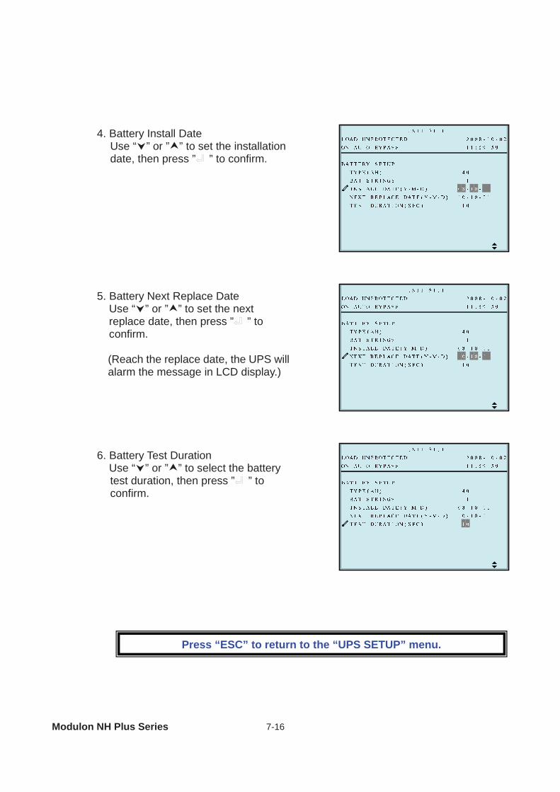
6. Battery Test Duration Use “ ” or ” ” to select the battery test duration, then press ” ” to confirm.
Press “ESC” to return to the “UPS SETUP” menu.
4. Battery Install Date Use “ ” or ” ” to set the installation date, then press ” ” to confirm.
5. Battery Next Replace Date Use “ ” or ” ” to set the next replace date, then press ” ” to confirm. (Reach the replace date, the UPS will alarm the message in LCD display.)
7 Display and Configuration
7-17
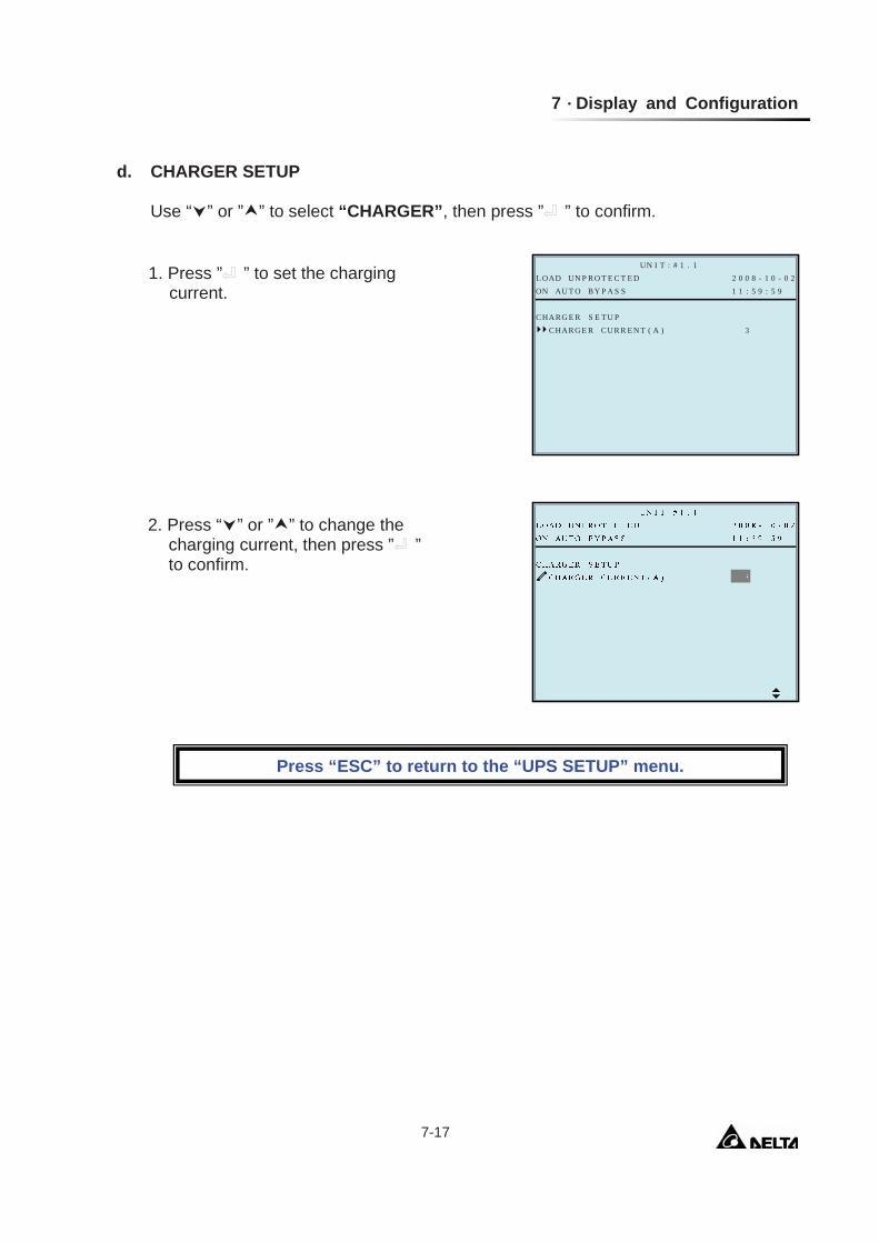
d. CHARGER SETUP
Use “ ” or ” ” to select “CHARGER”, then press ” ” to confirm.
E
P
RCHAR
2 0 0 8 - 1 0 - 0 2RO T E C T E DL OAD UNUN I T : # 1 . 1
1 1 : 5 9 : 5 9BY P A S SON AU T O
T ( A ) 3UR R E NCGCHAR
E RGS E T U P
1. Press ” ” to set the charging current.
2. Press “ ” or ” ” to change the charging current, then press ” ” to confirm.
Press “ESC” to return to the “UPS SETUP” menu.
Modulon NH Plus Series 7-18
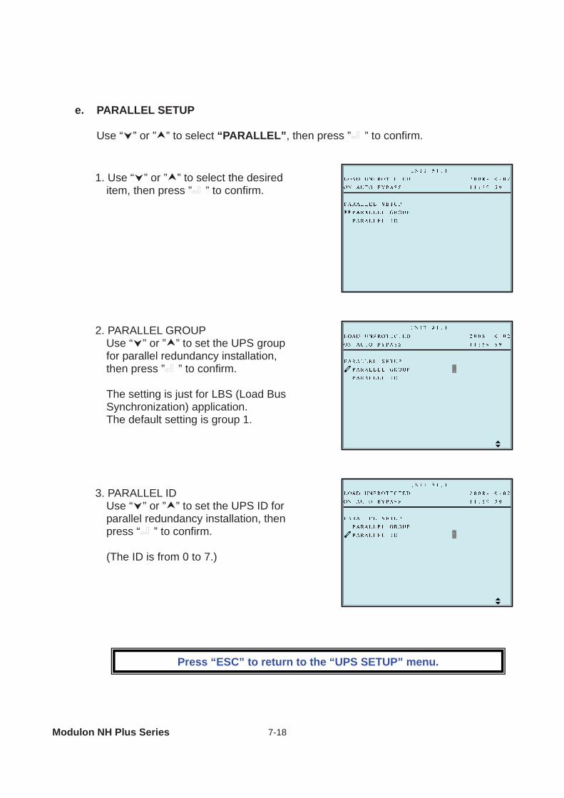
e. PARALLEL SETUP
Use “ ” or ” ” to select “PARALLEL”, then press ” ” to confirm.
3. PARALLEL ID Use “ ” or ” ” to set the UPS ID for parallel redundancy installation, then press “ ” to confirm. (The ID is from 0 to 7.)
1. Use “ ” or ” ” to select the desired item, then press ” ” to confirm.
2. PARALLEL GROUP Use “ ” or ” ” to set the UPS group for parallel redundancy installation, then press ” ” to confirm. The setting is just for LBS (Load Bus Synchronization) application. The default setting is group 1.
Press “ESC” to return to the “UPS SETUP” menu.
7 Display and Configuration
7-19
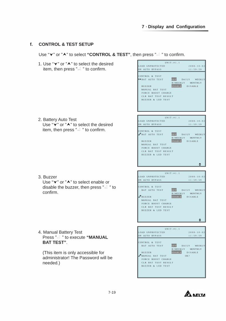
f. CONTROL & TEST SETUP
Use “ ” or ” ” to select “CONTROL & TEST”, then press ” ” to confirm.
1. Use “ ” or ” ” to select the desired item, then press ” ” to confirm.
O
P
EY
&L
LK L YBA T
E S U L TE S T& L E D TBU Z Z E R
2 0 0 8 - 1 0 - 0 2RO T E C T E DL OAD UNUN I T : # 1 . 1
1 1 : 5 9 : 5 9BY P A S SON AU T O
O F F DA I L Y WET E S TOI WE E K L Y MON T H
D I S AB L E
RCON T
B
ETT RS TC L R BA
U TA
ARG ESOBO HCTF OR C ET
AB L ETAB SETMANUA L
E NBU Z Z E R
T E S T
O
P
EY
&L
LK L YBA T
E S U L TE S T& L E D TBU Z Z E R
2 0 0 8 - 1 0 - 0 2RO T E C T E DL OAD UNUN I T : # 1 . 1
1 1 : 5 9 : 5 9BY P A S SON AU T O
O F F DA I L Y WET E S TOI WE E K L Y MON T H
D I S AB L EOK ?
RCON T
B
ETT RS TC L R BA
U TA
ARG ESOBO HCTF OR C ET
AB L ETAB SETMANUA L
E NBU Z Z E R
T E S T
2. Battery Auto Test Use “ ” or ” ” to select the desired item, then press ” ” to confirm.
3. Buzzer Use “ ” or ” ” to select enable or disable the buzzer, then press ” ” to confirm.
4. Manual Battery Test Press ” ” to execute “MANUAL BAT TEST”. (This item is only accessible for administrator! The Password will be needed.)
Modulon NH Plus Series 7-20
O
P
EY
&L
LK L YBA T
E S U L TE S T& L E D TBU Z Z E R
2 0 0 8 - 1 0 - 0 2RO T E C T E DL OAD UNUN I T : # 1 . 1
1 1 : 5 9 : 5 9BY P A S SON AU T O
O F F DA I L Y WET E S TOI WE E K L Y MON T H
D I S AB L E
OK ?
RCON T
B
ETT RS TC L R BA
U TA
ARG ESOBO HCTF OR C ET
AB L ETAB SETMANUA L
E NBU Z Z E R
T E S T
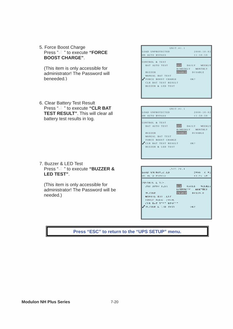
5. Force Boost Charge Press ” ” to execute “FORCE BOOST CHARGE”. (This item is only accessible for administrator! The Password will beneeded.)
6. Clear Battery Test Result Press “ ” to execute “CLR BAT TEST RESULT”. This will clear all battery test results in log.
7. Buzzer & LED Test Press “ ” to execute “BUZZER & LED TEST”. (This item is only accessible for administrator! The Password will be needed.)
Press “ESC” to return to the “UPS SETUP” menu.
7 Display and Configuration
7-21
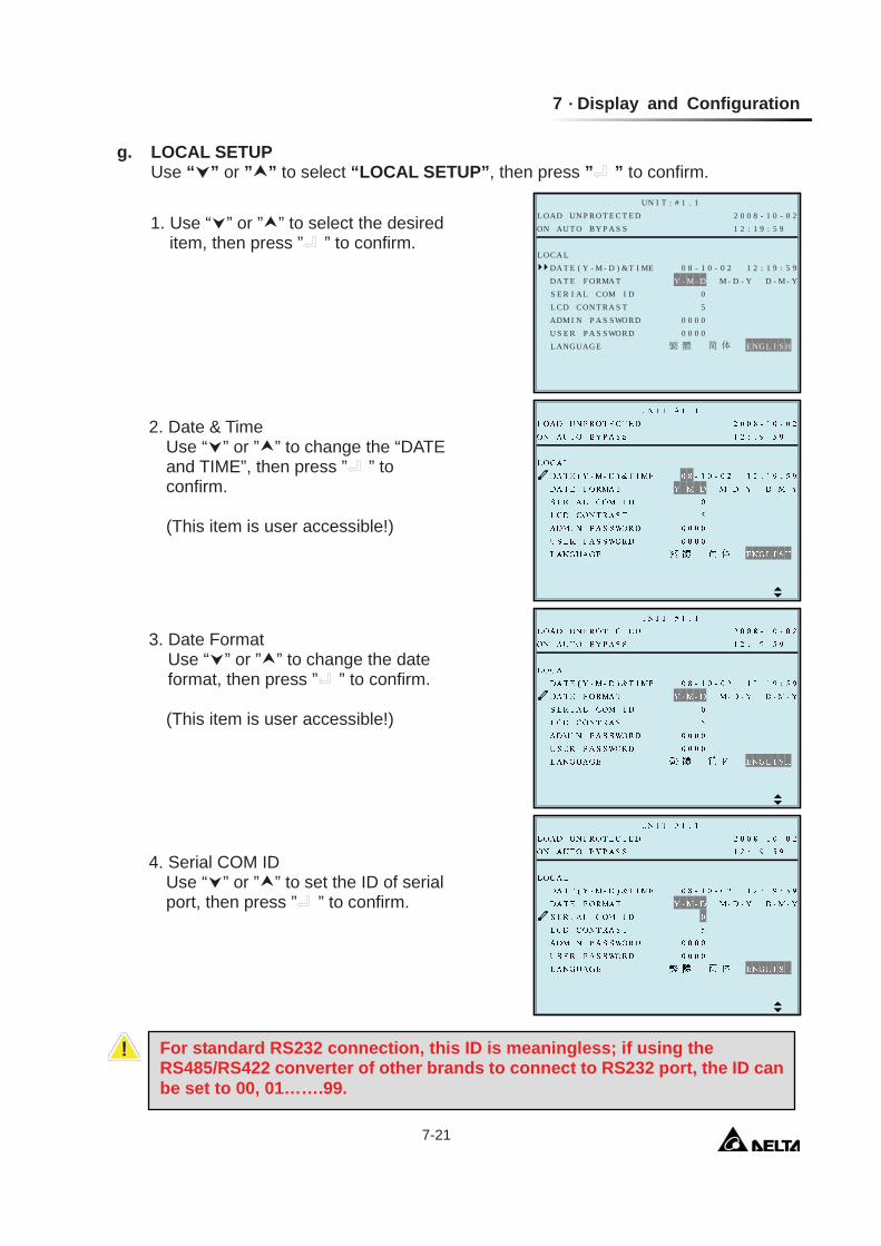
g. LOCAL SETUP Use “ ” or ” ” to select “LOCAL SETUP”, then press ” ” to confirm.
1. Use “ ” or ” ” to select the desired item, then press ” ” to confirm.
2. Date & Time Use “ ” or ” ” to change the “DATE and TIME”, then press ” ” to confirm. (This item is user accessible!)
3. Date Format Use “ ” or ” ” to change the date format, then press ” ” to confirm. (This item is user accessible!)
4. Serial COM ID Use “ ” or ” ” to set the ID of serial port, then press ” ” to confirm.
P
- M - Y9 : 5 9DA T E
0 0 0 0E NG L I S HG EL ANGUA
2 0 0 8 - 1 0 - 0 2RO T E C T E DL OAD UNUN I T : # 1 . 1
1 2 : 1 9 : 5 9BY P A S SON AU T O
ME 0 8 - 1 0 - 0 2 1 2 : 1- D ) &T IMY - M - D M - D - Y DT
0 0 0 0
LL OCA
MA
WSA S DORU S E R P
Y -(
SSP A DRWOADM I N50
ARN T S TL CD COMOC DIS E R I A L
DA T E RF O
For standard RS232 connection, this ID is meaningless; if using the RS485/RS422 converter of other brands to connect to RS232 port, the ID can be set to 00, 01…….99.
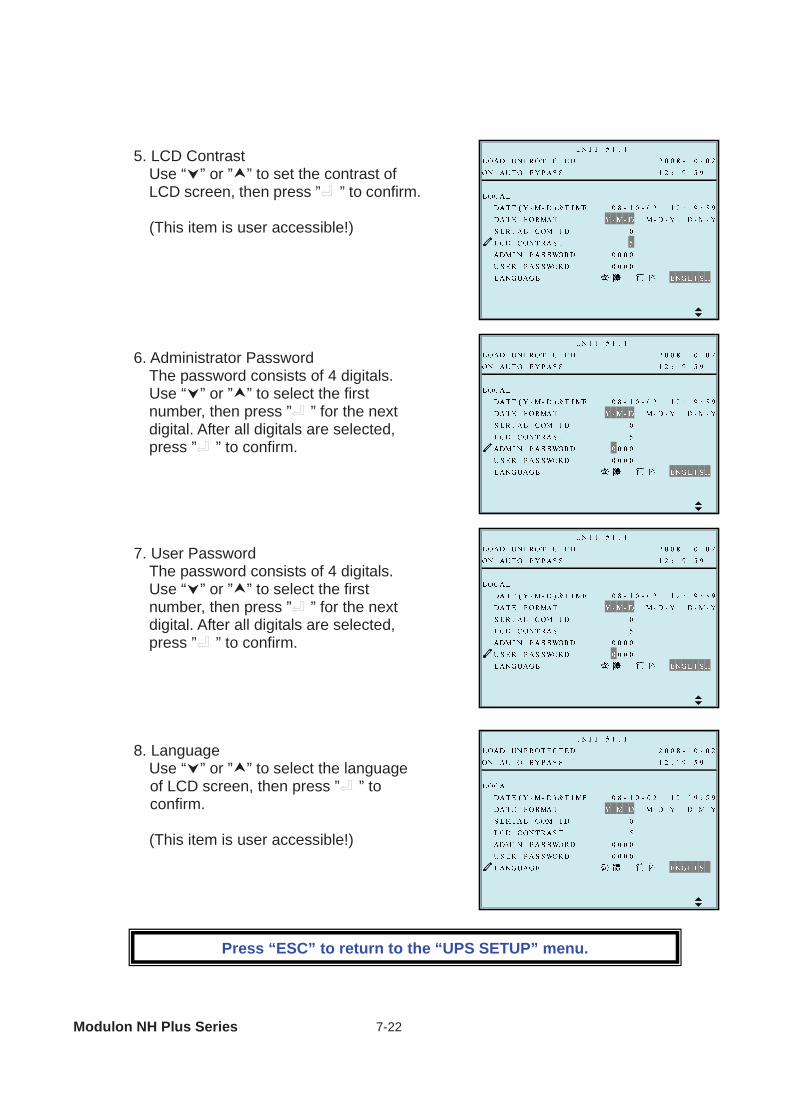
Modulon NH Plus Series 7-22
5. LCD Contrast Use “ ” or ” ” to set the contrast of LCD screen, then press ” ” to confirm. (This item is user accessible!)
6. Administrator Password The password consists of 4 digitals. Use “ ” or ” ” to select the first number, then press ” ” for the next digital. After all digitals are selected, press ” ” to confirm.
7. User Password The password consists of 4 digitals. Use “ ” or ” ” to select the first number, then press ” ” for the next digital. After all digitals are selected, press ” ” to confirm.
8. Language Use “ ” or ” ” to select the language of LCD screen, then press ” ” to confirm. (This item is user accessible!)
Press “ESC” to return to the “UPS SETUP” menu.
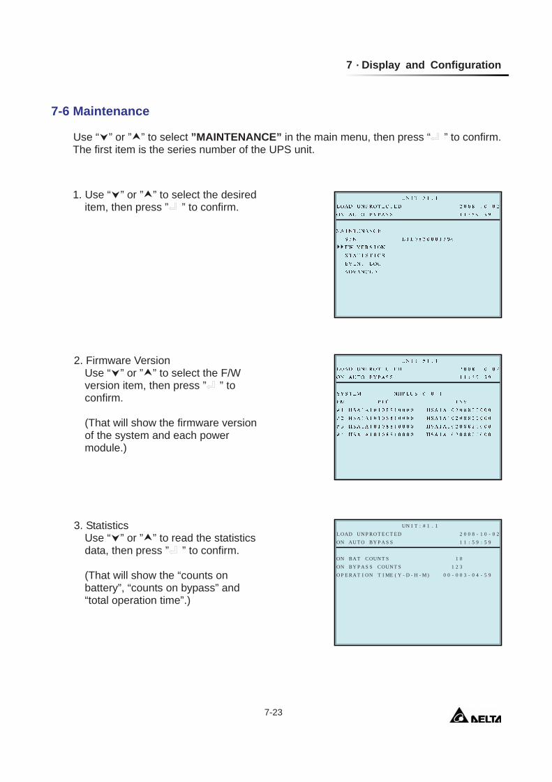
7 Display and Configuration
7-23
7-6 Maintenance
Use “ ” or ” ” to select ”MAINTENANCE” in the main menu, then press “ ” to confirm. The first item is the series number of the UPS unit.
1. Use “ ” or ” ” to select the desired item, then press ” ” to confirm.
2. Firmware Version Use “ ” or ” ” to select the F/W version item, then press ” ” to confirm. (That will show the firmware version of the system and each power module.)
T
P
5 9O P
1 0COON BY P
2 0 0 8 - 1 0 - 0 2RO T E C T E DL OAD UNUN I T : # 1 . 1
1 1 : 5 9 : 5 9BY P A S SON AU T O
1 2 3COUN T S- D M ) 0 0 - 0 0 3 - 0 4 -ME ( Y
AON B
T I - H -S SA
UN T S
E RA T ONI
3. Statistics Use “ ” or ” ” to read the statistics data, then press ” ” to confirm. (That will show the “counts on battery”, “counts on bypass” and “total operation time”.)
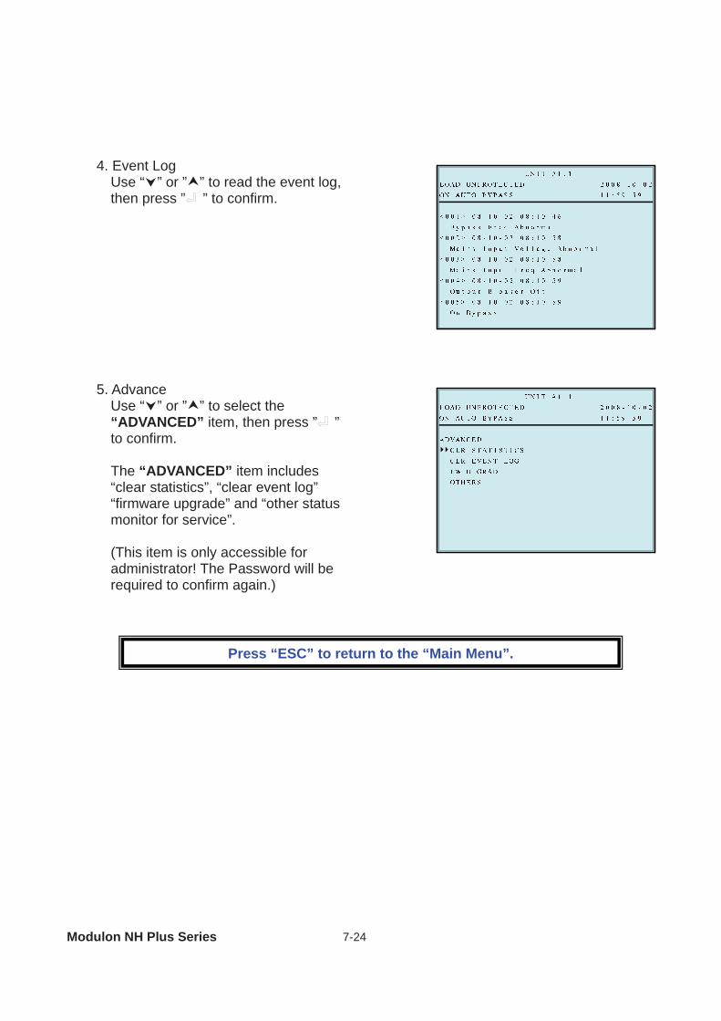
Modulon NH Plus Series 7-24
4. Event Log Use “ ” or ” ” to read the event log, then press ” ” to confirm.
5. Advance Use “ ” or ” ” to select the “ADVANCED” item, then press ” ” to confirm. The “ADVANCED” item includes “clear statistics”, “clear event log” “firmware upgrade” and “other status monitor for service”. (This item is only accessible for administrator! The Password will be required to confirm again.)
Press “ESC” to return to the “Main Menu”.
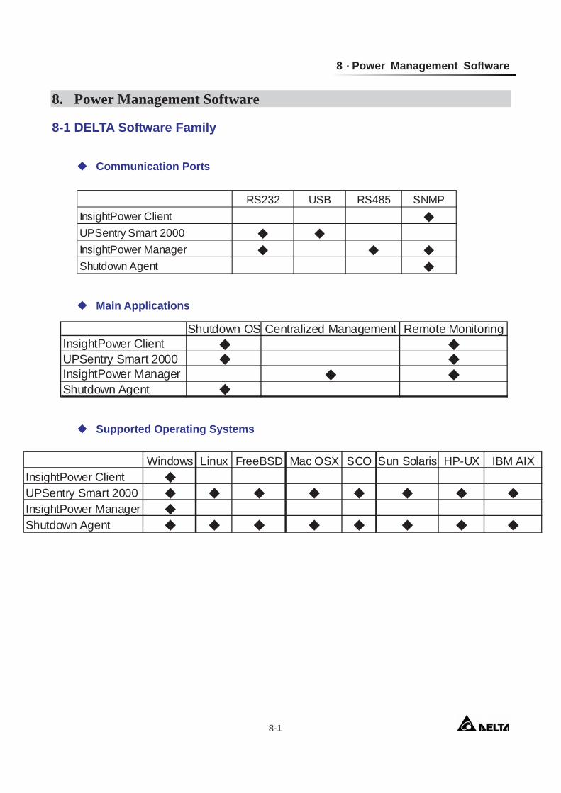
8 Power Management Software
8-1
8. Power Management Software 8-1 DELTA Software Family
Communication Ports
Main Applications
Supported Operating Systems
RS232 USB RS485 SNMPInsightPower ClientUPSentry Smart 2000InsightPower ManagerShutdown Agent
Shutdown OS Centralized Management Remote MonitoringInsightPower ClientUPSentry Smart 2000InsightPower ManagerShutdown Agent
Windows Linux FreeBSD Mac OSX SCO Sun Solaris HP-UX IBM AIXInsightPower ClientUPSentry Smart 2000InsightPower ManagerShutdown Agent
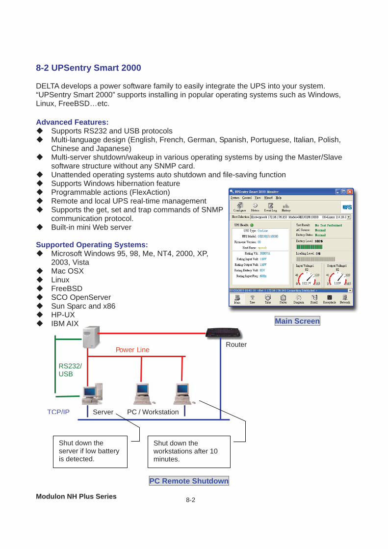
Modulon NH Plus Series 8-2
8-2 UPSentry Smart 2000 DELTA develops a power software family to easily integrate the UPS into your system. “UPSentry Smart 2000” supports installing in popular operating systems such as Windows, Linux, FreeBSD…etc.
Advanced Features: Supports RS232 and USB protocols Multi-language design (English, French, German, Spanish, Portuguese, Italian, Polish,
Chinese and Japanese) Multi-server shutdown/wakeup in various operating systems by using the Master/Slave
software structure without any SNMP card. Unattended operating systems auto shutdown and file-saving function Supports Windows hibernation feature Programmable actions (FlexAction) Remote and local UPS real-time management Supports the get, set and trap commands of SNMP
communication protocol. Built-in mini Web server
Supported Operating Systems:
Microsoft Windows 95, 98, Me, NT4, 2000, XP, 2003, Vista
Mac OSX Linux FreeBSD SCO OpenServer Sun Sparc and x86 HP-UX IBM AIX
Main Screen
Power Line
Server PC / WorkstationTCP/IP
RS232/USB
Router
Shut down the server if low battery is detected.
Shut down the workstations after 10 minutes.
PC Remote Shutdown
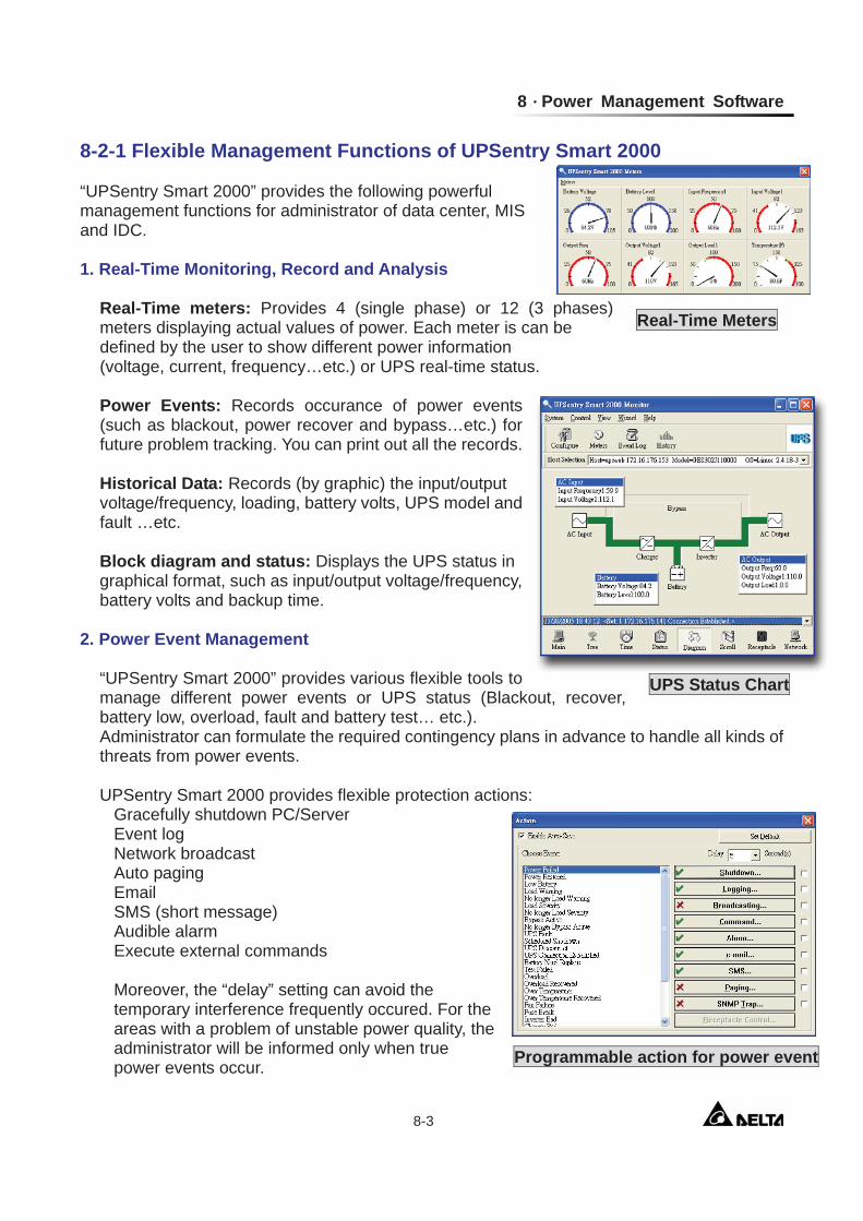
8 Power Management Software
8-3
8-2-1 Flexible Management Functions of UPSentry Smart 2000 “UPSentry Smart 2000” provides the following powerful management functions for administrator of data center, MIS and IDC. 1. Real-Time Monitoring, Record and Analysis
Real-Time meters: Provides 4 (single phase) or 12 (3 phases) meters displaying actual values of power. Each meter is can be defined by the user to show different power information (voltage, current, frequency…etc.) or UPS real-time status. Power Events: Records occurance of power events (such as blackout, power recover and bypass…etc.) for future problem tracking. You can print out all the records. Historical Data: Records (by graphic) the input/output voltage/frequency, loading, battery volts, UPS model and fault …etc. Block diagram and status: Displays the UPS status in graphical format, such as input/output voltage/frequency, battery volts and backup time.
2. Power Event Management
“UPSentry Smart 2000” provides various flexible tools to manage different power events or UPS status (Blackout, recover, battery low, overload, fault and battery test… etc.). Administrator can formulate the required contingency plans in advance to handle all kinds of threats from power events. UPSentry Smart 2000 provides flexible protection actions:
Gracefully shutdown PC/Server Event log Network broadcast Auto paging Email SMS (short message) Audible alarm Execute external commands Moreover, the “delay” setting can avoid the temporary interference frequently occured. For the areas with a problem of unstable power quality, the administrator will be informed only when true power events occur. Programmable action for power event
UPS Status Chart
Real-Time Meters
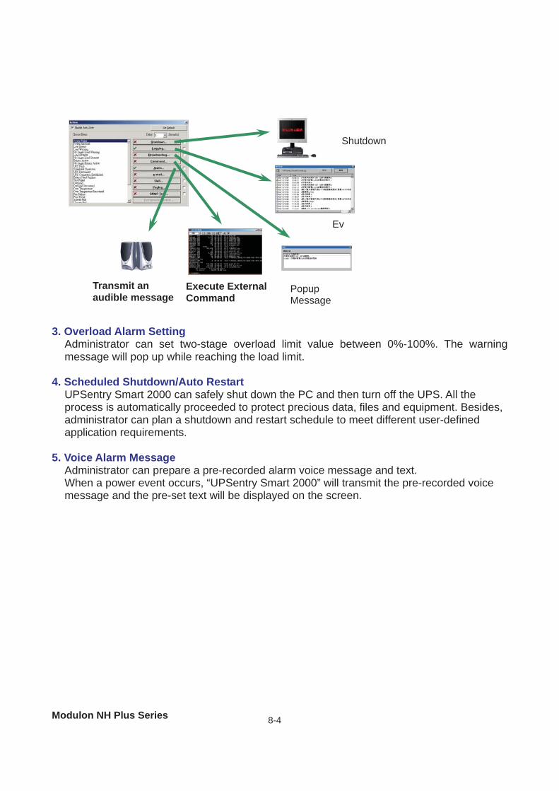
Modulon NH Plus Series 8-4
3. Overload Alarm Setting
Administrator can set two-stage overload limit value between 0%-100%. The warning message will pop up while reaching the load limit.
4. Scheduled Shutdown/Auto Restart UPSentry Smart 2000 can safely shut down the PC and then turn off the UPS. All the process is automatically proceeded to protect precious data, files and equipment. Besides, administrator can plan a shutdown and restart schedule to meet different user-defined application requirements.
5. Voice Alarm Message Administrator can prepare a pre-recorded alarm voice message and text. When a power event occurs, “UPSentry Smart 2000” will transmit the pre-recorded voice message and the pre-set text will be displayed on the screen.
Shutdown
Ev
Popup Message
Execute External Command
Transmit an audible message
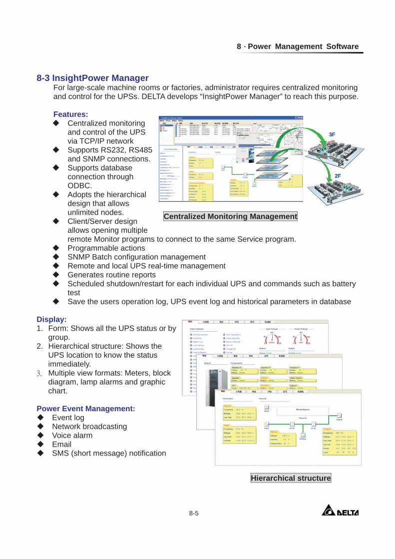
8 Power Management Software
8-5
8-3 InsightPower Manager
For large-scale machine rooms or factories, administrator requires centralized monitoring and control for the UPSs. DELTA develops “InsightPower Manager” to reach this purpose.
Features:
Centralized monitoring and control of the UPS via TCP/IP network
Supports RS232, RS485 and SNMP connections.
Supports database connection through ODBC.
Adopts the hierarchical design that allows unlimited nodes.
Client/Server design allows opening multiple remote Monitor programs to connect to the same Service program.
Programmable actions SNMP Batch configuration management Remote and local UPS real-time management Generates routine reports Scheduled shutdown/restart for each individual UPS and commands such as battery
test Save the users operation log, UPS event log and historical parameters in database
Display: 1. Form: Shows all the UPS status or by
group. 2. Hierarchical structure: Shows the
UPS location to know the status immediately.
Multiple view formats: Meters, block diagram, lamp alarms and graphic chart.
Power Event Management:
Event log Network broadcasting Voice alarm Email SMS (short message) notification
2F
3F
2F2F
3F3F
Centralized Monitoring Management
Hierarchical structure
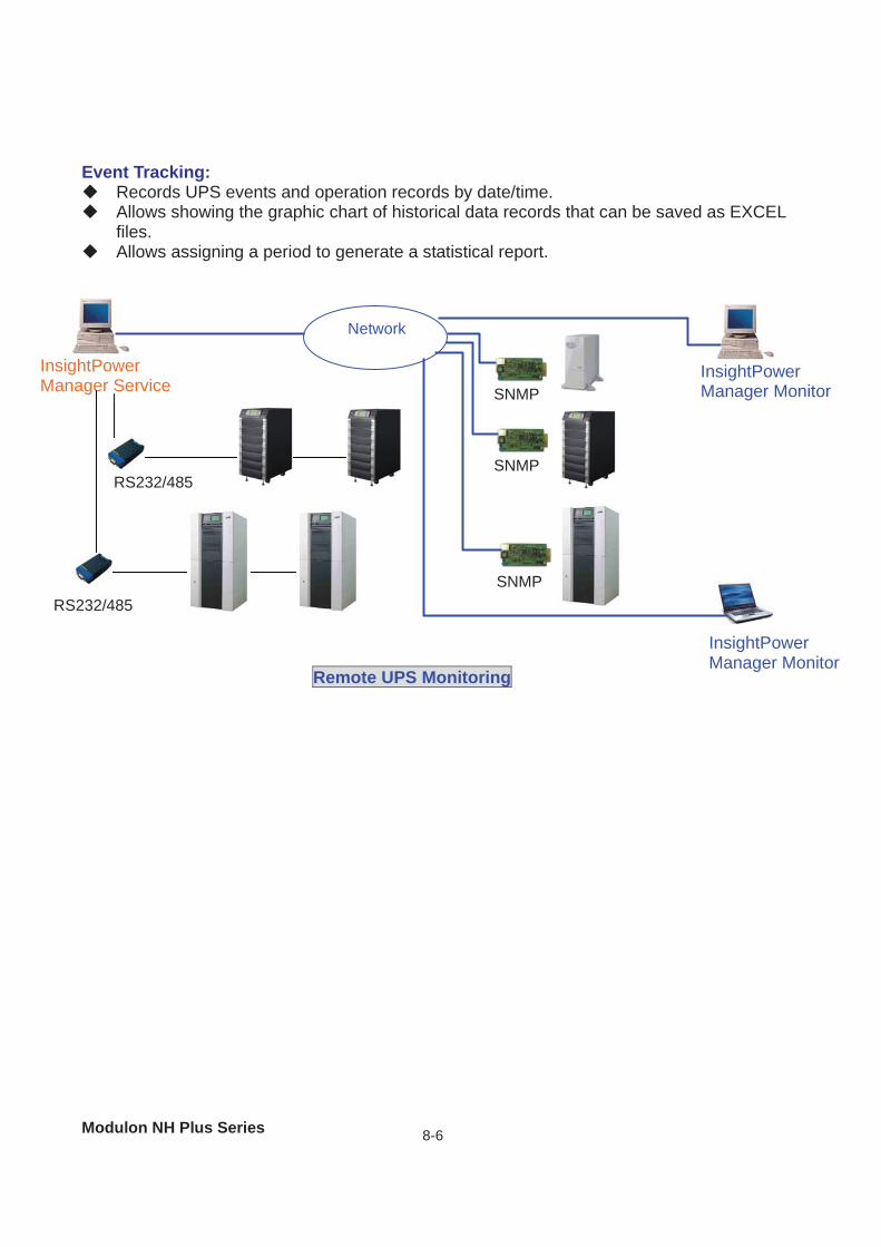
Modulon NH Plus Series 8-6
Event Tracking:
Records UPS events and operation records by date/time. Allows showing the graphic chart of historical data records that can be saved as EXCEL
files. Allows assigning a period to generate a statistical report.
SNMP
SNMP
SNMP
InsightPower Manager Service
RS232/485
RS232/485
Network
InsightPower Manager Monitor
InsightPower Manager Monitor
Remote UPS Monitoring
9 Warranty
9-1
9. Warranty Seller warrants this product, if used in accordance with all applicable instructions, to be free from original defects in material and workmanship within the warranty period. If the product has any failure problem within the warranty period, Seller will repair or replace the product at its sole discretion according to the failure situation. This warranty does not apply to normal wear or to damage resulting from improper installation, operation, usage, maintenance or irresistible force (i.e. war, fire, natural disaster, etc.), and this warranty also expressly excludes all incidental and consequential damages. Maintenance service for a fee is provided for any damage out of the warranty period. If any maintenance is required, please directly contact the supplier or Seller.
WARNING: The individual user should take care to determine prior to use whether the environment and the load characteristic are suitable, adequate or safe for the installation and the usage of this product. The User Manual must be carefully followed. Seller makes no representation or warranty as to the suitability or fitness of this product for any specific application.