DELTA HYDRO HOSE TESTER - Niedner Inc. of Contents INTRODUCTION 2 DELTA HYDRO Hose Tester...
16
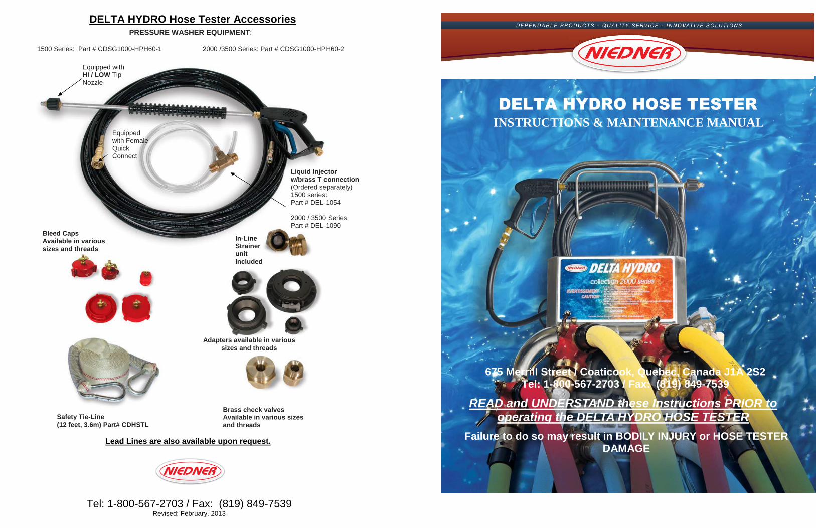
DELTA HYDRO Hose Tester Accessories Lead Lines are also available upon request. Tel: 1-800-567-2703 / Fax: (819) 849-7539 Revised: February, 2013 675 Merrill Street / Coaticook, Quebec, Canada J1A 2S2 Tel: 1-800-567-2703 / Fax: (819) 849-7539 READ and UNDERSTAND these Instructions PRIOR to operating the DELTA HYDRO HOSE TESTER Failure to do so may result in BODILY INJURY or HOSE TESTER DAMAGE Safety Tie-Line (12 feet, 3.6m) Part# CDHSTL Brass check valves Available in various sizes and threads Adapters available in various sizes and threads In-Line Strainer unit Included Bleed Caps Available in various sizes and threads PRESSURE WASHER EQUIPMENT: 1500 Series: Part # CDSG1000-HPH60-1 2000 /3500 Series: Part # CDSG1000-HPH60-2 Liquid Injector w/brass T connection (Ordered separately) 1500 series: Part # DEL-1054 2000 / 3500 Series Part # DEL-1090 DELTA HYDRO HOSE TESTER INSTRUCTIONS & MAINTENANCE MANUAL Equipped with Female Quick Connect Equipped with HI / LOW Tip Nozzle
Transcript of DELTA HYDRO HOSE TESTER - Niedner Inc. of Contents INTRODUCTION 2 DELTA HYDRO Hose Tester...
DELTA HYDRO Hose Tester Accessories
Lead Lines are also available upon request.
Tel: 1-800-567-2703 / Fax: (819) 849-7539 Revised: February, 2013
675 Merrill Street / Coaticook, Quebec, Canada J1A 2S2 Tel: 1-800-567-2703 / Fax: (819) 849-7539
READ and UNDERSTAND these Instructions PRIOR to operating the DELTA HYDRO HOSE TESTER
Failure to do so may result in BODILY INJURY or HOSE TESTER DAMAGE
Safety Tie-Line
(12 feet, 3.6m) Part# CDHSTL
Brass check valves Available in various sizes and threads
Adapters available in various
sizes and threads
In-Line Strainer unit
Included
Bleed Caps Available in various
sizes and threads
PRESSURE WASHER EQUIPMENT:
1500 Series: Part # CDSG1000-HPH60-1 2000 /3500 Series: Part # CDSG1000-HPH60-2
Liquid Injector w/brass T connection (Ordered separately) 1500 series: Part # DEL-1054 2000 / 3500 Series Part # DEL-1090
DELTA HYDRO HOSE TESTER
INSTRUCTIONS & MAINTENANCE MANUAL Equipped with Female Quick Connect
Equipped with HI / LOW Tip Nozzle

Table of Contents
INTRODUCTION .......................................................................................................... 2 DELTA HYDRO Hose Tester Maintenance and Care ................................................ 3 General ....................................................................................................... 3 Inspection ................................................................................................... 3 Lubrication .................................................................................................. 3 Filter Cleaning ............................................................................................ 3 Cautions ...................................................................................................... 7 DELTA HYDRO Hose Tester Operating Instructions ................................................ 5 Draining ....................................................................................................... 7 Storage ........................................................................................................ 7 Anti-freeze .................................................................................................. 7 NFPA 1962 (2008 edition) Reference Section ............................................................ 9 Pressure Washer Operation ..................................................................................... 13 Using Pressure Washer Equipment ......................................................... 13 Using the Liquid Injector .......................................................................... 13 Q & A DELTA HYDRO Hose Tester Trouble Shooting ............................................. 14 Slow pressurization .................................................................................. 14 No pressure build up ................................................................................ 14 Cloudy / White / Milky Pump oil ............................................................... 15 DELTA HYDRO Hose Tester features chart ............................................................ 17 Parts list and Diagrams for Niedner DELTA HYDRO Hose Tester 1500 Electrical Low Profile Series ........................................................... 18 2000 Electrical Stand-Up Series ............................................................... 20 2000 Electrical Low Profile Series ............................................................ 22 2000 Gas Stand-Up Series ....................................................................... 24 2000 Gas Low Profile Series .................................................................... 26 3500 Electrical Stand-Up Series .............................................................. 28 DELTA HYDRO Hose Tester Accessories ................................................. Back Cover
Since the beginning Niedner has been committed to procuring all of its raw materials from only North American suppliers. It is our belief that not only will this allow us to maintain the highest level of quality and workmanship but also to ensure the future employment of both American and Canadian workers in this industry and its related supply chain. With over 115 years of expertise in manufacturing high quality products, a state of the art manufacturing plant and an ISO 9000 compliant quality system we are proud to be the hose supplier of choice to those who demand the utmost in quality and performance from their hose products.

PERSONAL NOTES:
OUR COMMITMENT
Niedner is committed to providing the highest quality of Customer Service! Our Customer Service is delivered to you with a sense of warmth, friendliness, individual pride and
Company Spirit.
We acknowledge that to do well in a changing technological world we will need to work in a climate of curiosity, adaptability, initiative and risk taking.
We use our knowledge and experience to interpret your needs and pass on information. We are prepared to learn about your specific requirements and assist you with them. When we receive a
request that we many not be able to accommodate, we will do our best to recommend an alternative method which may be of assistance to you.
We take responsibility for what we do and how we do it. We use our resources wisely, ensuring that we provide the highest value for your investment. We acknowledge that we may make
mistakes occasionally but we will learn from them and use this additional knowledge to further enhance our service to you.
We value principles, such as honesty, courtesy, truthfulness and equity.
28
INTRODUCTION
Niedner’s DELTA HYDRO Hose Tester is the only hose tester with both patented stainless steel manifold and automatic safety check valves. The stainless steel material used in the manifold contributes to an extended life by not deteriorating prematurely. Unlike other hose testers that have ball valves requiring hands-on operation during tests, the DELTA HYDRO Hose Tester has automatic check valves that create a safety margin for the fire fighter during hose test pressurization. These check valves are fully automatic, allowing the operator to maintain a safe distance while testing hose.
Niedner’s greatest concern is that personnel will be struck by a whipping burst hose line. Creating a safety perimeter will prevent this disaster. The automatic check valves on all DELTA HYDRO Hose Testers enhance this safety zone and minimize the chance of injury.
DELTA HYDRO Hose Testers have the following high quality features:
Reliable top quality oil bath pump for consistent performance, constant lubrication and long life.
A powerful industrial motor as a power source on all the electric hose testers, except the CDHT3500 model that is equipped with a 4.0 HP ODP (open drip proof) motor.
Stainless steel construction for corrosion-free long life.
Designed to meet or exceed NFPA guidelines.
A one year limited warranty.
DELTA HYDRO Hose Testers should be used by competent, trained personnel within the prescribed guidelines, as set forth by the manufacturer and NFPA.
Failure of a DELTA HYDRO Hose Tester under pressure may cause serious bodily injury or property damage.
For safety reasons, Niedner strongly urges that all lengths of hoses being tested should be tied together with Safety Tie-Lines (available from your Niedner Distributor). This will minimize the chance of injury should a hose burst.
Niedner disclaims any and all liability for injury or damage to any and all persons or property that may be caused by the operation of the DELTA HYDRO Hose Tester, whether it is a result of misunderstanding of instructions, lack of prudent safety precautions or not following the safety standards of the industry.
All questions should be directed to your Niedner Distributor or to Niedner
1-800-567-2703
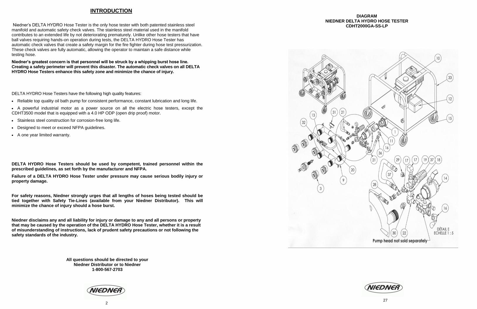
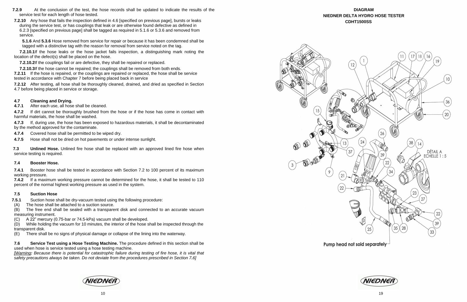
DIAGRAM NIEDNER DELTA HYDRO HOSE TESTER
CDHT2000GA-SS-LP
2
27
DELTA HYDRO Hose Tester Maintenance and Care
GENERAL: The DELTA HYDRO Hose Tester should be stored at room temperature. No water should be left sitting in the unit over long periods of time.
INSPECTION: Before each use, as recommended by NFPA 1962 (2008 edition), visually inspect the DELTA HYDRO Hose Tester and all of its components, including the Check Valve Assemblies. To inspect the check valve assemblies, for possible corrosion and/or foreign matter, carefully dismantle the check valve assembly with your fingers and pull out the center disc. Visually inspect the condition of the O-ring on the center disc. If any of the O-rings are missing, cracked or damaged, they must be replaced. Replacements parts are available to you from your Niedner Distributor.
LUBRICATION: DELTA HYDRO Hose Testers have a break-in period of 50 hours of operation.
After this period, the pump oil should be changed, and thereafter be changed after every 3-5 months or 200 hours of operation (whichever comes first).
The proper oil level for all DELTA HYDRO Hose Testers’ models is in the middle of the “sight glass”, or at the cut notch on the dipstick. IMPROPER PUMP LUBRICATION WILL VOID THE WARRANTY.
Part # Source Motor oil
Recommended
Pump oil
Recommended
CDHT1500SS Electric Not Applicable 5W-30 Synthetic
CDHT2000SS Electric Not Applicable 5W-30 Synthetic
CDHT2000GA-SS Gas 10W-30 Synthetic 5W-30 Synthetic For lubrication of the gasoline engine, refer to the gasoline engine manufacturer’s manual.
FILTER CLEANING: The DELTA HYDRO Hose Tester is equipped with an In-Line Water Strainer for efficient operation. To clean this filter, unscrew the filter casing and remove the strainer inside. Flush thoroughly with water, or replace the in-line water strainer unit entirely if it is damaged or corroded, replacement part available from your Niedner Distributor. See parts list and schematic diagram to locate this part on your DELTA HYDRO Hose Tester.
CAUTIONS
3 inch (76 mm) and/or Larger Diameter Hose: All 3”, 3½”, 4”, 5”, and 6” (76, 89, 102, 127 and 152 mm) hoses are to be tested flat on the ground with the use of Lead lines which are short, smaller diameter sections of hose which are placed between the tester and the sections of hose(s) being tested. No sections of large diameter hose should ever be connected directly to the DELTA HYDRO Hose Tester check valves.
Pump Heat Build-Up: The DELTA HYDRO Hose Tester is equipped with a positive displacement oil bath pump. An oil bath pump normally runs cooler than other types of pumps, but care must still be taken. With the pump operating, the pressure regulator directs water back into the inlet side of the pump, creating a closed loop re-circulating action. This causes heat to build up inside the pump. Caution must be used to prevent the pump temperature from exceeding 160° F (71°C). Once the desired test pressure is reached, the pump should be turned off, allowing the check valves to hold the pressure for the three-minute period specified by NFPA.
*** HEAT DAMAGE WILL VOID THE WARRANTY ***
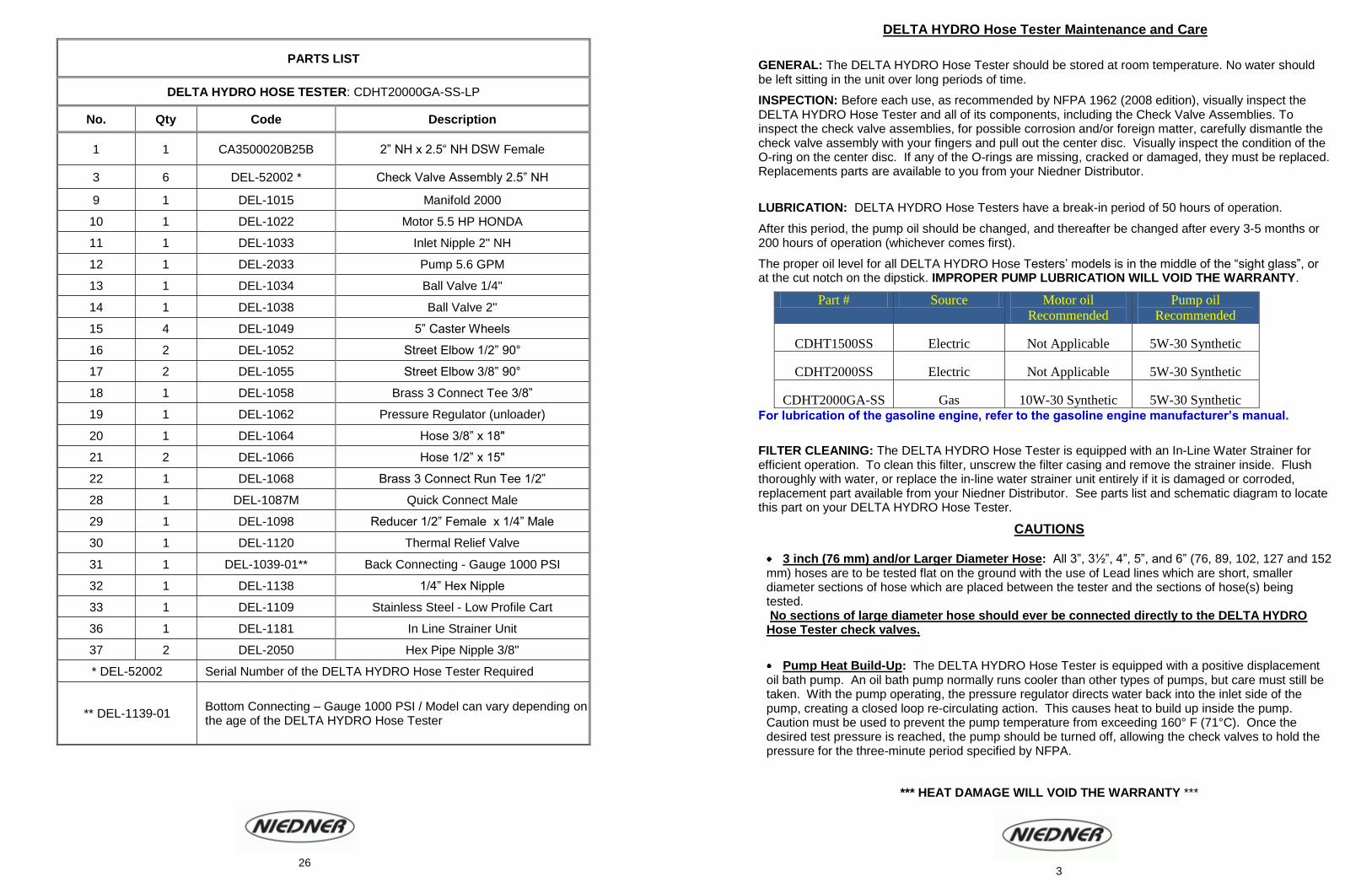
PARTS LIST
DELTA HYDRO HOSE TESTER: CDHT20000GA-SS-LP
No. Qty Code Description
1 1 CA3500020B25B 2” NH x 2.5“ NH DSW Female
3 6 DEL-52002 * Check Valve Assembly 2.5” NH
9 1 DEL-1015 Manifold 2000
10 1 DEL-1022 Motor 5.5 HP HONDA
11 1 DEL-1033 Inlet Nipple 2" NH
12 1 DEL-2033 Pump 5.6 GPM
13 1 DEL-1034 Ball Valve 1/4"
14 1 DEL-1038 Ball Valve 2"
15 4 DEL-1049 5” Caster Wheels
16 2 DEL-1052 Street Elbow 1/2” 90°
17 2 DEL-1055 Street Elbow 3/8” 90°
18 1 DEL-1058 Brass 3 Connect Tee 3/8”
19 1 DEL-1062 Pressure Regulator (unloader)
20 1 DEL-1064 Hose 3/8” x 18"
21 2 DEL-1066 Hose 1/2” x 15"
22 1 DEL-1068 Brass 3 Connect Run Tee 1/2”
28 1 DEL-1087M Quick Connect Male
29 1 DEL-1098 Reducer 1/2” Female x 1/4” Male
30 1 DEL-1120 Thermal Relief Valve
31 1 DEL-1039-01** Back Connecting - Gauge 1000 PSI
32 1 DEL-1138 1/4” Hex Nipple
33 1 DEL-1109 Stainless Steel - Low Profile Cart
36 1 DEL-1181 In Line Strainer Unit
37 2 DEL-2050 Hex Pipe Nipple 3/8"
* DEL-52002 Serial Number of the DELTA HYDRO Hose Tester Required
** DEL-1139-01 Bottom Connecting – Gauge 1000 PSI / Model can vary depending on the age of the DELTA HYDRO Hose Tester
3 26

Inlet water pressure: Inlet water pressure should not exceed 120 psi (827 kPa), or non-warranty internal damage can occur to the pump.
Safety Tie Lines: Properly tying the hoses together at every coupling connection with the designed safety tie-line will secure the hoses together for stability and safety in case of hose failure.
Gas Engine DELTA HYDRO Hose Testers: Running the gas model DELTA HYDRO Hose Tester at full throttle speed is not required. The throttle setting/speed should be half speed or slightly higher is usually sufficient. Using the sound of the engine as a guide, strive for a smooth, vibration-free operation. Excessive vibration will reduce the life expectancy of the DELTA HYDRO Hose Tester, and could cause damage/or breakage to part.
Electrical Extension Cords: Electrical extension cord should NOT BE USED with any of the electric DELTA HYDRO Hose Tester models.
** Unless the extension cord is properly sized of the appropriate amperage rating of the electric motor. Should an inappropriate amperage rating electrical cord be used, it may cause non-warranty damage.
Maximum Safety: Be sure to carefully read, understand and follow all instructions in this booklet and in accordance with NFPA 1962 (2008 edition). Personnel safety is the first priority in all hose testing evolutions.
Water: NEVER RUN THE PUMP WITHOUT AN ADAQUATE WATER SUPPLY!
Returns: Any and all returns must have an authorisation number approved by Niedner.
All liquids are to be REMOVED from the hose tester prior to shipping. Any DELTA HYDRO Hose Tester being shipped with flammable liquids must have the appropriate MSDS sheets included with the shipment paperwork. Niedner must be advised of this prior to shipment.
Warning: The GFCI (Ground Fault Circuit Interrupter) wall plug provided is recommended when using electric appliances in close proximity to conductive fluids.
DIAGRAM
NIEDNER DELTA HYDRO HOSE TESTER CDHT2000GA-SS
4 25
DELTA HYDRO Hose Tester Operating Instructions [Note: Become thoroughly familiar with these Instructions & Maintenance Manual AND NFPA Standard 1962 (2008 edition) before operating the DELTA HYDRO Hose Tester]
1. Position the DELTA HYDRO Hose Tester on a hard, flat, and stable surface. If the test site has any incline, place the Hose Tester at the lowest part of the incline, with the hose discharge ends at the highest position. It must be placed so it is NOT tilted more than 10 degrees off vertical. This will help all air to be expelled from the hose. NOTE: All hose being tested together must be of the same Service Test Pressure. 2. Checking fluid levels: Electric models: check the oil levels in the pump. Gas models: check the oil levels in the pump as well as the fuel and oil levels in the gas engine. Levels should be centered in sight glass or at the appropriate level on the dipstick. 3. Connect the section(s) of hose(s) being tested to the DELTA HYDRO Hose Tester outlets. Cap off any unused check valve outlet with the appropriate size OPEN bleed cap and NOT a BLIND cap. The Maximum length of hose PER OUTLET should not exceed 300 feet. WARNING: All 3”or larger diameter hose should be tested using the bottom outlets only and should be connected to lead lines. Lead lines are short lengths of smaller diameter hose which have the same or greater service pressure ratings. Large diameter hoses should NEVER be attached directly to any DELTA HYDRO Hose Tester check valves.
4. Attach the Bleed caps to all the discharge ends of hose. Make sure the petcock on the bleed cap is in the open position. Niedner highly recommends that all hose be tied together at the coupling connection with a safety Tie-Line. Safety Tie-Lines are available from your Niedner Distributor. The use of the Safety Tie-lines is for safety reasons. Having the hoses tied together will minimize the chances of injury should a hose burst during its testing phase. 5. Connect the DELTA HYDRO Hose Tester to water supply of your choice. The inlet water pressure should not exceed 120 PSI, or non-warranty internal damage to the pump could occur. 6. For the electric model DELTA HYDRO Hose Tester, be sure to plug in the DELTA HYDRO Hose Tester into a grounded 20 Amp circuit. The use of an electrical extension cord with the improper electrical amperage rating may cause non-warranty damage to your hose tester unit. The use of an electrical extension cord is NEVER recommended, unless it is rated for the appropriate amperage. 7. The use of the GFCI wall plug (Ground Fault Circuit Interrupter) is highly recommended when using the DELTA HYDRO Hose Tester in close proximity with conductive fluids, such as water. 8. Open both ball valves on the DELTA HYDRO Hose Tester, and turn the water supply on. Allow the water to flow through out the DELTA HYDRO Hose Tester, until all the air has been evacuated from the unit. When there is a steady stream of water being expelled from the sections of hose, close the bleed caps by turning the petcock in the opposite direction. 9. Close the main water supply inlet ball valve. DO NOT SHUT OFF the water supply. 10. Closing the inlet ball valve forces the water supply to redirect itself into the pump. Having a continuous supply of water circulating into the pump will keep it from overheating. Shutting off main water supply entirely could damage the pump and cause non warranty damage to your DELTA HYDRO Hose Tester.
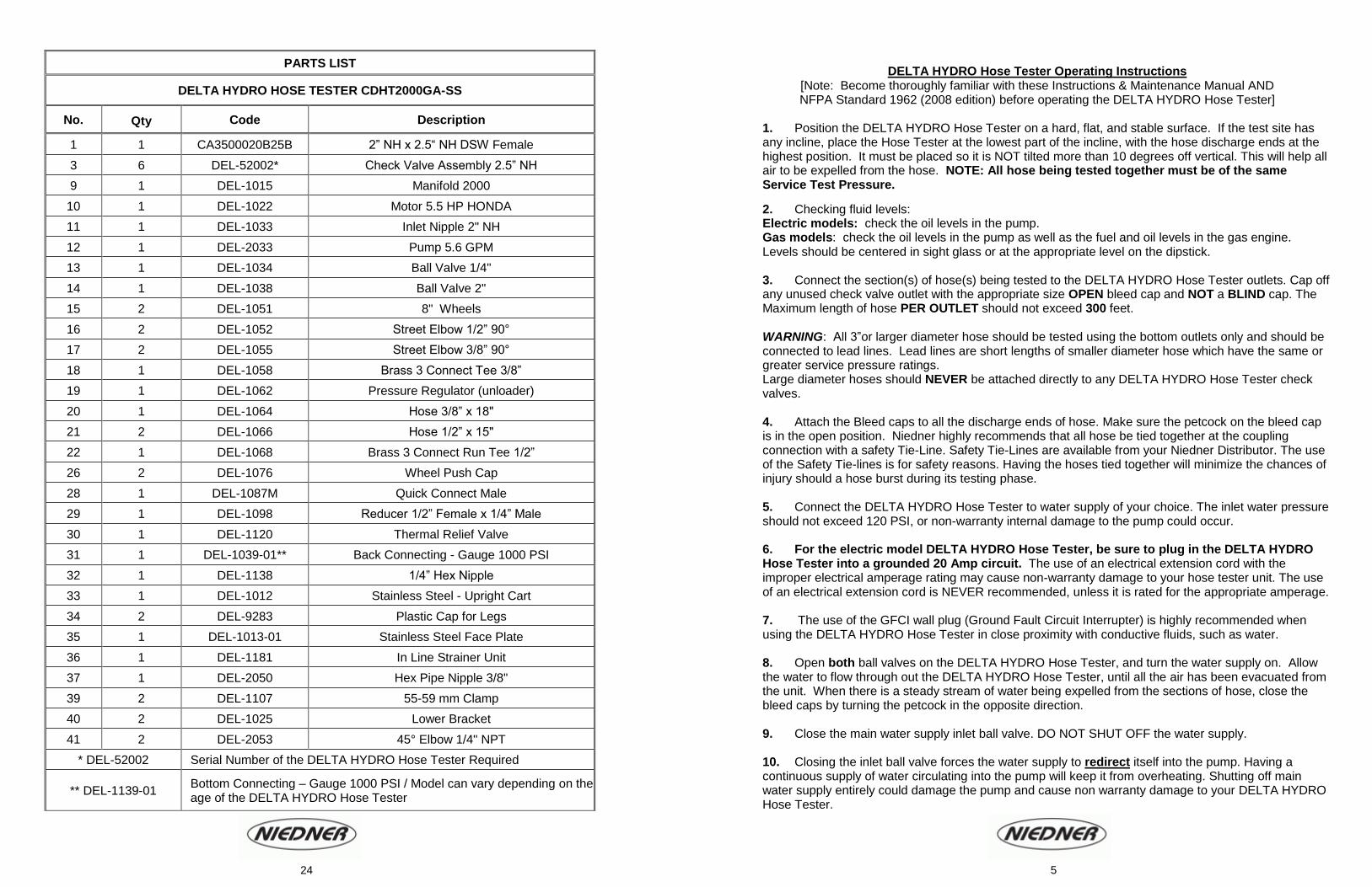
PARTS LIST
DELTA HYDRO HOSE TESTER CDHT2000GA-SS
No. Qty Code Description
1 1 CA3500020B25B 2” NH x 2.5“ NH DSW Female
3 6 DEL-52002* Check Valve Assembly 2.5” NH
9 1 DEL-1015 Manifold 2000
10 1 DEL-1022 Motor 5.5 HP HONDA
11 1 DEL-1033 Inlet Nipple 2" NH
12 1 DEL-2033 Pump 5.6 GPM
13 1 DEL-1034 Ball Valve 1/4"
14 1 DEL-1038 Ball Valve 2"
15 2 DEL-1051 8" Wheels
16 2 DEL-1052 Street Elbow 1/2” 90°
17 2 DEL-1055 Street Elbow 3/8” 90°
18 1 DEL-1058 Brass 3 Connect Tee 3/8”
19 1 DEL-1062 Pressure Regulator (unloader)
20 1 DEL-1064 Hose 3/8” x 18"
21 2 DEL-1066 Hose 1/2” x 15"
22 1 DEL-1068 Brass 3 Connect Run Tee 1/2”
26 2 DEL-1076 Wheel Push Cap
28 1 DEL-1087M Quick Connect Male
29 1 DEL-1098 Reducer 1/2” Female x 1/4” Male
30 1 DEL-1120 Thermal Relief Valve
31 1 DEL-1039-01** Back Connecting - Gauge 1000 PSI
32 1 DEL-1138 1/4” Hex Nipple
33 1 DEL-1012 Stainless Steel - Upright Cart
34 2 DEL-9283 Plastic Cap for Legs
35 1 DEL-1013-01 Stainless Steel Face Plate
36 1 DEL-1181 In Line Strainer Unit
37 1 DEL-2050 Hex Pipe Nipple 3/8"
39 2 DEL-1107 55-59 mm Clamp
40 2 DEL-1025 Lower Bracket
41 2 DEL-2053 45° Elbow 1/4" NPT
* DEL-52002 Serial Number of the DELTA HYDRO Hose Tester Required
** DEL-1139-01 Bottom Connecting – Gauge 1000 PSI / Model can vary depending on the age of the DELTA HYDRO Hose Tester
5 24

11. It is normal to see water being expelled from the thermal relief valve. ** CAUTION ** the water being expelled from the Thermal Relief Valve is HOT! The function of the Thermal Relief Valve is to remove the heated water from the pump to allow room for the cooler water from the main water supply. 12. At this point the hoses are filled and are completely purged and/or bled of air. The Gauge on the DELTA HYDRO Hose Tester should show a reading from 50 PSI to120 PSI hydrant pressure. If the Gauge needle has NOT moved from its original position, STOP the DELTA HYDRO Hose Tester. The Gauge may be damaged / broker or be faulty. If the Gauge is fine, skip to step 14. 13. Do not resume using the DELTA HYDRO Hose Tester unit until has been inspected by a trained mechanic and/or the faulty Gauge has been replaced. Replacement parts are available from your Niedner Distributor (see parts list).
14. Make sure the Pressure Regulator is set at the minimum pressure BEFORE starting up the DELTA HYDRO Hose Tester. The minimum setting is achieved by turning the Pressure Regulator in the counter clock wise direction.
15. Start up the DELTA HYDRO Hose Tester, and slowly turn the handle of the Pressure Regulator in a clockwise direction until the desired test pressure is indicated on the Gauge.
DO NOT force the handle of the Pressure Regulator beyond is normal resistance point.
If the gas model DELTA HYDRO Hose Tester is being used, the engine should be run at a smooth consistent throttle speed, anywhere from 1/3 to 1/2 of its throttle speed. Use the sound of the gas engine as a guide to strive for a smooth, vibration free operational throttle.
Excessive vibration will reduce the life expectancy of the DELTA HYDRO Hose Tester.
16. The pressurization time will vary, this process may take anywhere from 20 to 30 minutes, or longer, depending on the size, type and quantity of hose being tested.
Also, the diameter of the water supply hose may contribute to a longer fill time. However, the inlet of the water supply hose should be of the same or greater diameter size as the inlet of the hose tester.
** Warning: The Pump should NEVER be started or run without an adequate supply of water flowing through the pump plumbing and the DELTA HYDRO Hose Tester manifold. Damage to equipment, personnel injury, or death may result if the pump is operated without an adequate water supply.
17. Once all lengths of hose have successfully been tested, return the handle of the Pressure Regulator to its original positioning (completely counter-clockwise direction).
** IMPORTANT: Turn off the DELTA HYDRO Hose Tester BEFORE turn off the main water supply. Shutting off the water supply while the pump is still operating may result in non-warranty damage to the DELTA HYDRO Hose Tester unit or to other equipment or serious personnel injury.
18. Open all the bleed caps by turning the petcock in the appropriate direction in order to drain all the water from the hose. Remove the bleed caps, Safety-Tie Lines (if applicable) and Lead lines (if applicable) and store everything in the appropriate location.
DIAGRAM NIEDNER DELTA HYDRO HOSE TESTER
CDHT2000SS-LP
6 23

19. To remove the last of the water from the DELTA HYDRO Hose Tester, slowly tip the Hose Tester unit forward until all water is removed.
20. DELTA HYDRO Hose Tester units which are frequently subject to salt water or brackish water conditions need to be FLUSHED CLEAN with Fresh water after each used.
21. Also DELTA HYDRO Hose Tester units which are used in salt water or brackish water conditions should be equipped with special ordered BRASS Check Valve Assemblies. The Brass Check Vales are available to you from your Niedner Distributor.
22. Unless otherwise specified, the DELTA HYDRO Hose Tester comes equipped with Aluminum Check Valve Assembly.
Niedner disclaims any and all liability for injury or damage to any and all persons or property that may be caused by the operation of the DELAT HYDRO Hose Tester, whether it is a result of misunderstanding of the instructions, lack of prudent safety precautions or not following the safety standards of the industry.
DRAINING THE HOSE TESTER AFTER A SERVICE TEST
FLUSHING: If salt water or brackish water has been used, flush the Hose Tester and the Pressure Washer equipment thoroughly with fresh water after each use. Remove all bleed caps and store separately.
DRAINING: To drain the water from the DELTA HYDRO Hose Tester, use a small screwdriver and your fingers to carefully pull out the center disc of one of the check valves from the bottom outlet check valves. Carefully insert the screwdriver behind the center disc to keep the check valve open. Then, gradually tilt the Hose Tester forward, until all water has drained. [Do not allow the oil to leak from the dipstick opening when tilting DELTA HYDRO Hose Tester.]
Short term or long term storage of the DELTA HYDRO Hose Tester
Short terms storage: (up to 3 months):
In ABOVE freezing weather conditions drain the water from the Hose Tester by following the above steps. As an additional measure, low pressure compressed air is blown through the open water inlet valve to remove the remainder of the water from the inside of the unit
Long term storage: (+3 months):
In BELOW freezing weather conditions drain all the water from the unit using the above steps, as well as adding a storage adapter (which can be purchased from Niedner). Low pressure compressed air is blown through the open water inlet valve to remove the remainder of the water from the inside of the unit.
ANTI-FREEZE: In colder climates, extra steps are required. Niedner recommends the following steps be taken to protect and prolong the life of your DELTA HYDRO Hose Tester:
PARTS LIST
DELTA HYDRO HOSE TESTER : CDHT2000SS-LP
No. Qty Code Description 2000 LP
1 1 CA3500020B25B 2” NH x 2.5” NH DSW Female
3 6 DEL-52002 * Check Valve Assembly 2.5” NH
9 1 DEL-1015-51 Manifold 2000
10 1 DEL-1121 Motor 1.7 HP / 60 Hz
11 1 DEL-1033 Inlet Nipple 2" NH
12 1 DEL-1034 Ball Valve 1/4"
13 1 DEL-1036 Pump 4.3 GPM
14 1 DEL-1038 Ball Valve 2"
15 1 DEL-1039-01** Back Connecting - Gauge 1000 PSI
16 1 DEL-1041/21 120 volt Electric Cord
18 1 DEL-1042 Toggle Switch
19 1 DEL-1043 Toggle Switch Boot
20 1 DEL-1045-14/3 Strain Relief Connector
21 4 DEL-1049 5” Caster Wheels
22 3 DEL-1052 Street Elbow 1/2” 90°
23 2 DEL-1055 Street Elbow 3/8” 90°
24 1 DEL-1058 Brass 3 Connect Tee 3/8”
25 1 DEL-1062 Pressure Regulator (unloader)
26 1 DEL-1064 Hose 3/8” x 18"
27 2 DEL-1066 Hose 1/2” x 15"
28 1 DEL-1068 Brass 3 Connect Run Tee 1/2”
32 1 DEL-1087M Quick Connect Male
33 1 DEL-1098 Reducer 1/2” Female x 1/4” Male
34 1 DEL-1109 Stainless Steel – Low Profile Cart
35 1 DEL-1120 Thermal Relief Valve
36 1 DEL-1138 1/4” Hex Nipple
37 1 DEL-1181 In Line Strainer Unit
38 2 DEL-2050 Hex Pipe Nipple 3/8"
Not Shown 1 DEL-1046/120V GFCI Module 120V
* DEL-52002 Serial Number of the DELTA HYDRO Hose Tester Required.
** DEL-1139-01 Bottom Connecting – Gauge 1000 PSI / Model can vary depending on the age of the DELTA HYDRO Hose Tester.
22 7
The pumps water way should be filled with a solution made up of 50% water and 50% ethylene glycol anti-freeze. Follow these steps:
Close the inlet ball valve.
Using blind caps (available from your Niedner Distributor) cap off all but ONE of the check valves on the unit.
** Recommended: If you have a 1500 model leave the top outlet uncapped
If you have a 2000 or 3500 model leave one of the two top outlets uncapped.
This will allow the air to escape as you are filling the unit with the anti-freeze mixture. Carefully insert the head of a small screwdriver into the un-capped check valve, as described previously for venting purposes.
Remove the In-Line Water Strainer.
Attach a 3 foot (0.9 m) piece of garden hose with a female GHT (Garden Hose Thread) to the In-Line Water Strainer connection.
With a funnel in the garden hose, slowly pour in the anti-freeze mixture (of 50% water and 50% ethylene glycol ) into the unit until full, at about which time the anti-freeze mixture will seep out from the uncapped check valve openings.
When the anti-freeze mixture seeps through the check valve, remove the small screwdriver and cap off the check valve.
Remove the funnel and clamp off the open end of the garden hose, so that it will not leak during storage. The water inlet can be capped off with the appropriate size fitting if the garden hose needs to be removed for storage. The In-line water strainer should be kept in a safe place as it will need to be put back onto the unit when it is taken out of storage.
** Suggestion: Place the in-line strainer unit in a plastic bag and tape it to a secure spot on the cart of the Hose Tester or keep it with the DELTA HYDRO Hose Tester manual.
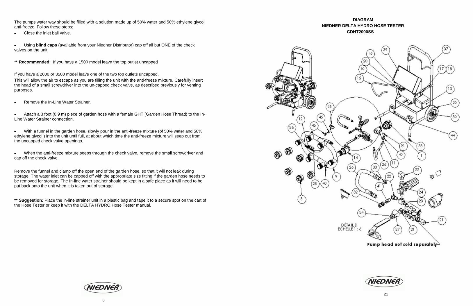
DIAGRAM
NIEDNER DELTA HYDRO HOSE TESTER
CDHT2000SS
8
21

The following procedures have been extracted from NFPA 1962 (2008 edition) [With Niedner notes in brackets and italics]
7.2 Service Test Procedure.
7.2.1 Each length of hose to be service-tested shall be inspected as specified in Section 4.6.
4.6 Hose Inspection.
4.6.1 Physical inspection shall determine that the hose, couplings, and any nozzle have not been vandalized, are free of debris, and exhibit no evidence of mildew, rot, or damage by chemicals, burns, cuts, abrasion, and vermin. 4.6.2 During the inspection, a check shall be made to determine if the service test of the hose is current.
4.6.3 Liner Inspection.
4.6.3.1 The interior of the hose at each end shall be visually inspected for any physical signs of liner delamination. 4.6.3.2 If the liner shows signs of delamination, the hose shall be condemned.
4.6.4 If the hose fails the physical inspection, it shall be removed from service and either repaired as necessary and service-tested as specified in Chapter 7 or condemned.
4.6.5 The couplings shall be inspected as specified in 6.2.3 and 6.2.4. 6.2.3 After each use, and during each hose service test, couplings shall be visually inspected for the following defects:
(1) Damaged threads (2) Corrosion (3) Slippage on the hose (4) Out-of-round (5) Connections not rotating freely (6) Missing lugs (7) Loose external collar (8) Internal gasket defects (9) Other defects that impair operation
6.2.4 Hose with defective couplings shall be removed from service and the couplings repaired or replaced.
7.2.2 Any length of hose that fails the inspection shall be removed from the service test area and repaired as necessary or condemned.
7.2.3 Lengths of hose to be tested simultaneously shall be of the same service test pressure and collectively, shall be considered the hose test layout.
7.2.4 The total length of any hose line in the hose test layout to be service-tested shall not exceed 300 ft (91 m).
7.2.5 The hose test layout shall be straight, without kinks or twists.
7.2.6 All 3 ½” (89 mm) and larger diameter hose shall be service-tested while lying flat with a short length of smaller diameter hose with the same or higher proof pressure used to connect the pressure source #series Testers].
7.2.7 A test location shall be selected that allows connection of the hose testing apparatus (pressure source) to a water source.
7.2.8 A hose testing machine, a stationary pump, or a pump on a fire department apparatus shall be used as a pressure source.
7.2.8.1 If a hose testing machine is used, the procedure defined in Section 7.6 shall be used.
7.2.8.2 If a stationary pump or a pump on a fire department apparatus is used, the procedure defined in Section 7.7 shall be used [see page 11 of NFPA 1962 – 2008 edition).
PARTS LIST
DELTA HYDRO HOSE TESTER : CDHT2000SS
No. Qty Code Description
1 1 CA3500020B25B 2“ NH x 2.5“ NH DSW Female
3 6 DEL-52002 * 2.5” Check Valve Assembly
9 1 DEL-1015 Manifold 2000
10 1 DEL-1121 Motor 1.7 HP / 60 Hz
11 1 DEL-1033 Inlet Nipple 2" NH
12 1 DEL-1034 Ball Valve 1/4"
13 1 DEL-1036 Pump 4.3 GPM
14 1 DEL-1038 Ball Valve 2"
15 1 DEL-1041/21 120 volt Electric Cord
17 1 DEL-1042 Toggle Switch
18 1 DEL-1043 Toggle Switch Boot
19 1 DEL-1045-14/3 Strain Relief Connector
20 2 DEL-1051 8" Wheels
21 3 DEL-1052 Street Elbow 1/2” 90°
22 2 DEL-1055 Street Elbow 3/8” 90°
23 1 DEL-1058 Brass 3 Connect Tee 3/8”
24 1 DEL-1062 Pressure Regulator (unloader)
25 1 DEL-1064 Hose 3/8” x 18"
26 2 DEL-1066 Hose 1/2” x 15"
27 1 DEL-1068 Brass 3 Connect Run Tee 1/2”
30 2 DEL-1076 Wheel Push Cap
32 1 DEL-1087M Quick Connect Male
33 1 DEL-1098 Reducer 1/2” Female x 1/4” Male
34 1 DEL-1120 Thermal Relief Valve
35 1 DEL-1039-01 ** Back Connecting - Gauge 1000 PSI
36 1 DEL-1138 1/4” Hex Nipple
37 1 DEL-1012 Stainless Steel - Upright Cart
38 2 DEL-9283 Plastic Cap for Legs
39 1 DEL-1013-01 Stainless Steel Face Plate
40 1 DEL-1181 In Line Strainer Unit
41 2 DEL-2050 Hex Pipe Nipple 3/8"
43 2 DEL-1107 55-59 mm Clamp
44 2 DEL-1025 Lower Bracket
45 2 DEL-2053 45° Elbow 1/4" NPT
Not Shown 1 DEL-1046/120v GFCI Module 120v
* DEL-52002 Serial Number of the DELTA HYDRO Hose Tester Required.
** DEL-1139-01 Bottom Connecting – Gauge 1000 PSI / Model can vary depending on the age of the DELTA HYDRO Hose Tester
9 20
7.2.9 At the conclusion of the test, the hose records shall be updated to indicate the results of the
service test for each length of hose tested.
7.2.10 Any hose that fails the inspection defined in 4.6 [specified on previous page], bursts or leaks during the service test, or has couplings that leak or are otherwise found defective as defined in 6.2.3 [specified on previous page] shall be tagged as required in 5.1.6 or 5.3.6 and removed from service.
5.1.6 And 5.3.6 Hose removed from service for repair or because it has been condemned shall be tagged with a distinctive tag with the reason for removal from service noted on the tag.
7.2.10.1If the hose leaks or the hose jacket fails inspection, a distinguishing mark noting the location of the defect(s) shall be placed on the hose.
7.2.10.2If the couplings fail or are defective, they shall be repaired or replaced.
7.2.10.3If the hose cannot be repaired; the couplings shall be removed from both ends. 7.2.11 If the hose is repaired, or the couplings are repaired or replaced, the hose shall be service tested in accordance with Chapter 7 before being placed back in service
7.2.12 After testing, all hose shall be thoroughly cleaned, drained, and dried as specified in Section 4.7 before being placed in service or storage.
4.7 Cleaning and Drying. 4.7.1 After each use, all hose shall be cleaned.
4.7.2 If dirt cannot be thoroughly brushed from the hose or if the hose has come in contact with harmful materials, the hose shall be washed.
4.7.3 If, during use, the hose has been exposed to hazardous materials, it shall be decontaminated by the method approved for the contaminate.
4.7.4 Covered hose shall be permitted to be wiped dry.
4.7.5 Hose shall not be dried on hot pavements or under intense sunlight.
7.3 Unlined Hose. Unlined fire hose shall be replaced with an approved lined fire hose when service testing is required.
7.4 Booster Hose.
7.4.1 Booster hose shall be tested in accordance with Section 7.2 to 100 percent of its maximum working pressure. 7.4.2 If a maximum working pressure cannot be determined for the hose, it shall be tested to 110 percent of the normal highest working pressure as used in the system.
7.5 Suction Hose
7.5.1 Suction hose shall be dry-vacuum tested using the following procedure: (A) The hose shall be attached to a suction source. (B) The free end shall be sealed with a transparent disk and connected to an accurate vacuum measuring instrument. (C) A 22” mercury (0.75-bar or 74.5-kPa) vacuum shall be developed. (D) While holding the vacuum for 10 minutes, the interior of the hose shall be inspected through the transparent disk. (E) There shall be no signs of physical damage or collapse of the lining into the waterway.
7.6 Service Test using a Hose Testing Machine. The procedure defined in this section shall be used when hose is service tested using a hose testing machine. [Warning: Because there is potential for catastrophic failure during testing of fire hose, it is vital that safety precautions always be taken. Do not deviate from the procedures prescribed in Section 7.6]
DIAGRAM
NIEDNER DELTA HYDRO HOSE TESTER
CDHT1500SS 10 19
7.6.1 Testing Machine Integrity. The condition of the hose testing machine shall be thoroughly checked daily before each testing session and before the machine is used after being transported to a new testing site
7.6.1.1 The hose testing machine shall be carefully examined for damaged components that might fail during the test.
7.6.1.2 If any damage is discovered, the hose testing machine shall not be used until the damaged component(s) is repaired or replaced.
7.6.1.3 A pressure leak integrity test shall be performed on the machine to determine whether the pressurized outlet side of the machine and its related components are leak-free.
7.6.1.3.1 The fire hose outlet connection(s) of the machine shall be capped or otherwise closed.
7.6.1.3.2 Pressure shall be applied through the machine using the integral pump to a level that is 10 percent higher than the highest service test pressure needed for the hose to be tested.
7.6.1.3.3 The pressure shall be held for 3 minutes with the pump turned off. Note that the gauge will drop to a 0 reading and this is due to the location of the gauge on the hose tester. In order to see a pressure reading, you will need to either use a line gauge or close the ¼” ball valve (part #del-1034).
7.6.1.3.4 If leaks are detected, the testing machine shall not be used until the leaking component(s) is repaired or replaced.
7.6.1.4 The test gauge that is used to read the test pressure shall have been calibrated within the previous twelve months.
7.6.2 Conducting the test
7.6.2.1 The test layout shall be connected to the outlet side of the water supply valve [check valve] on the hose testing machine.
7.6.2.2 A test cap with a bleeder valve shall be attached to the far end of each hose line in the test layout. If a test cap is not available, a nozzle with a non-twist shutoff shall be permitted to be used.
7.6.2.3 With the test cap valve or the nozzle open, the pressure shall be raised gradually to 45 psi +/- 5 psi (310 kPa +/- 35 kPa).
7.6.2.4 After the hose test layout is full of water, all the air in each hose line shall be exhausted by raising the discharge end of each hose line above the highest point in the system.
[Niedner Warning: Take care to remove all air from the hose before the test cap valve or the nozzle is closed and the pressure raised. If air remains in the system, a serious accident could occur]
7.6.2.5 Each nozzle or test cap valve shall be closed slowly, and then the outlet water supply valve (check valves) shall be closed. [Niedner’s DELTA HYDRO Hose Tester’s check valves close automatically].
7.6.2.6 The hose directly in back of the test cap or the nozzle shall be secured to avoid possible whipping or other uncontrolled reactions in the event that a hose bursts.
[Niedner insists on securing hoses at every coupling – i.e. – 3 lengths being tested out of one outlet – should be tied three times with safety tie lines – PART # CDHSTL sold separately].
7.6.2.7 With the hose at 45 psi +/- 5 psi (3.1 bar +/- 0.35 bar or 310 kPa +/- 35 kPa), it shall be checked for leakage at each coupling and the couplings tightened with a spanner wrench where necessary.
7.6.2.8 Each hose shall then be marked at the end or back of each coupling to determine, after the hose has been drained, if the coupling has slipped during the test.
[Niedner Warning: Once hose is filled and completely purged (or bled) of air, the pressure gauge should read anywhere from 50 PSI to 120 PSI hydrant pressure. If the needle in the gauge has not moved yet, the gauge may be faulty. Stop the hose test and do not resume until the gauge is replaced].
PARTS LIST
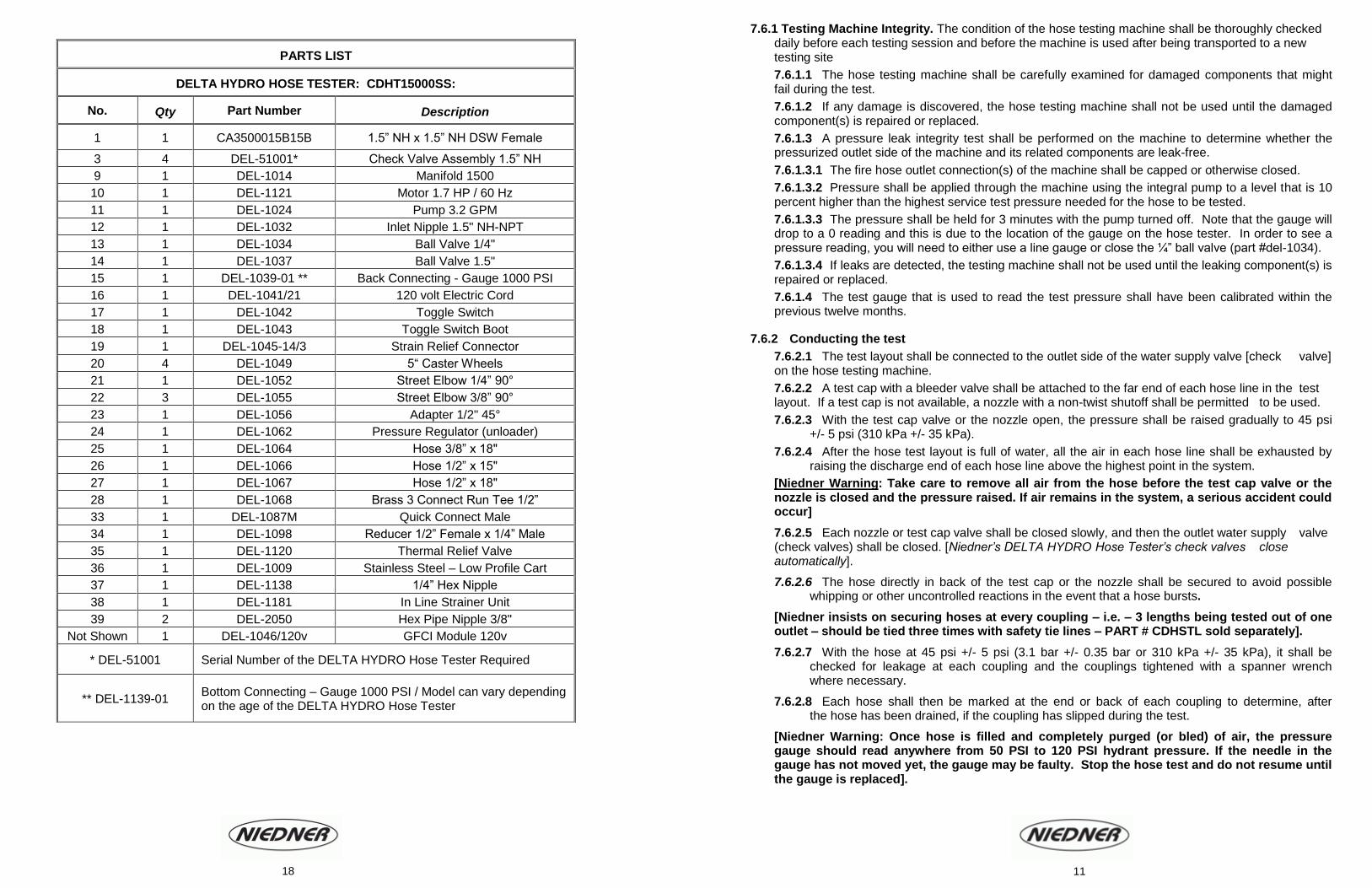
DELTA HYDRO HOSE TESTER: CDHT15000SS:
No. Qty Part Number Description
1 1 CA3500015B15B 1.5” NH x 1.5” NH DSW Female
3 4 DEL-51001* Check Valve Assembly 1.5” NH
9 1 DEL-1014 Manifold 1500
10 1 DEL-1121 Motor 1.7 HP / 60 Hz
11 1 DEL-1024 Pump 3.2 GPM
12 1 DEL-1032 Inlet Nipple 1.5" NH-NPT
13 1 DEL-1034 Ball Valve 1/4"
14 1 DEL-1037 Ball Valve 1.5"
15 1 DEL-1039-01 ** Back Connecting - Gauge 1000 PSI
16 1 DEL-1041/21 120 volt Electric Cord
17 1 DEL-1042 Toggle Switch
18 1 DEL-1043 Toggle Switch Boot
19 1 DEL-1045-14/3 Strain Relief Connector
20 4 DEL-1049 5“ Caster Wheels
21 1 DEL-1052 Street Elbow 1/4” 90°
22 3 DEL-1055 Street Elbow 3/8” 90°
23 1 DEL-1056 Adapter 1/2" 45°
24 1 DEL-1062 Pressure Regulator (unloader)
25 1 DEL-1064 Hose 3/8” x 18"
26 1 DEL-1066 Hose 1/2” x 15"
27 1 DEL-1067 Hose 1/2” x 18"
28 1 DEL-1068 Brass 3 Connect Run Tee 1/2”
33 1 DEL-1087M Quick Connect Male
34 1 DEL-1098 Reducer 1/2” Female x 1/4” Male
35 1 DEL-1120 Thermal Relief Valve
36 1 DEL-1009 Stainless Steel – Low Profile Cart
37 1 DEL-1138 1/4” Hex Nipple
38 1 DEL-1181 In Line Strainer Unit
39 2 DEL-2050 Hex Pipe Nipple 3/8"
Not Shown 1 DEL-1046/120v GFCI Module 120v
* DEL-51001 Serial Number of the DELTA HYDRO Hose Tester Required
** DEL-1139-01 Bottom Connecting – Gauge 1000 PSI / Model can vary depending on the age of the DELTA HYDRO Hose Tester
11 18
7.6.2.9 All personnel other than those persons required to perform the remainder of the procedure shall
clear the area.
7.6.2.10 Water supply should be closed and the pressure should be raised slowly at a rate not greater than 15 psi (1 bar or 103 kPa) per second until the service test pressure is attained and then maintained, by pressure boosts if necessary, for the duration of the stabilization period. [Niedner note: Using the pressure regulator – black handle: clockwise = increase, and counter-clockwise = decrease].
7.6.2.11 The stabilization period shall be not less than 1 minute per 100 ft. (30 m) of hose in the test layout
7.6.2.12 After the stabilization period, the hose layout shall hold the service test pressure for three minutes without further pressure boosts.
7.6.2.13 While the hose test layout is at the service test pressure, it shall be inspected for leaks.
7.6.2.13.1 If the inspecting personnel walk the test layout to inspect for leaks, they shall be at least 15 ft. (4.5 m) to the left side of the nearest hose line in the (hose) test layout. The left side of the hose line shall be defined as that side that is to the left when facing the free end from the pressure source.
7.6.2.13.2 Personnel shall never stand in front of the free end of the hose, on the right side of the hose, or closer than 15 ft. (4.5 m) on the left side of the hose, or straddle a hose in the test layout during the test.
7.6.2.14 If the hose test layout does not hold the service test pressure for the 3-minute duration, the service test shall be terminated.
7.6.2.14.1 The length(s) of hose that leaked shall have failed the test.
7.6.2.14.2 The test layout shall be drained and the defective hose removed from the test layout.
7.6.2.14.3 The service test shall be restarted beginning with the procedures required in 7.6.2.1.
7.6.2.15 After three minutes at the service test pressure, each test cap or nozzle shall be opened to drain the test layout.
7.6.2.16 Coupling Slippage.
7.6.2.16.1 The marks placed on the hose at the back of the couplings shall be observed for coupling slippage.
7.6.2.16.2 If the coupling has slipped, the hose shall have failed the test.
End of NFPA references
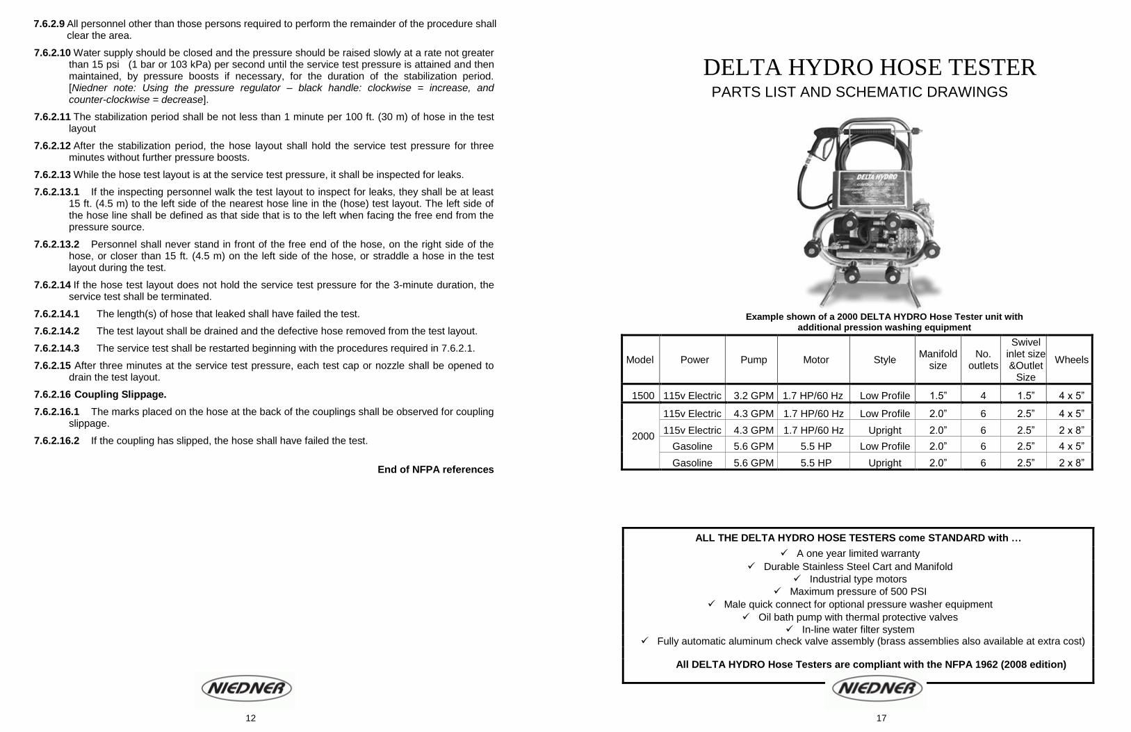
DELTA HYDRO HOSE TESTER PARTS LIST AND SCHEMATIC DRAWINGS
Example shown of a 2000 DELTA HYDRO Hose Tester unit with
additional pression washing equipment
Model Power Pump Motor Style Manifold
size No.
outlets
Swivel inlet size &Outlet
Size
Wheels
1500 115v Electric 3.2 GPM 1.7 HP/60 Hz Low Profile 1.5” 4 1.5” 4 x 5”
2000
115v Electric 4.3 GPM 1.7 HP/60 Hz Low Profile 2.0” 6 2.5” 4 x 5”
115v Electric 4.3 GPM 1.7 HP/60 Hz Upright 2.0” 6 2.5” 2 x 8”
Gasoline 5.6 GPM 5.5 HP Low Profile 2.0” 6 2.5” 4 x 5”
Gasoline 5.6 GPM 5.5 HP Upright 2.0” 6 2.5” 2 x 8”
ALL THE DELTA HYDRO HOSE TESTERS come STANDARD with …
A one year limited warranty
Durable Stainless Steel Cart and Manifold
Industrial type motors
Maximum pressure of 500 PSI
Male quick connect for optional pressure washer equipment
Oil bath pump with thermal protective valves
In-line water filter system Fully automatic aluminum check valve assembly (brass assemblies also available at extra cost)
All DELTA HYDRO Hose Testers are compliant with the NFPA 1962 (2008 edition)
Standards
12 17
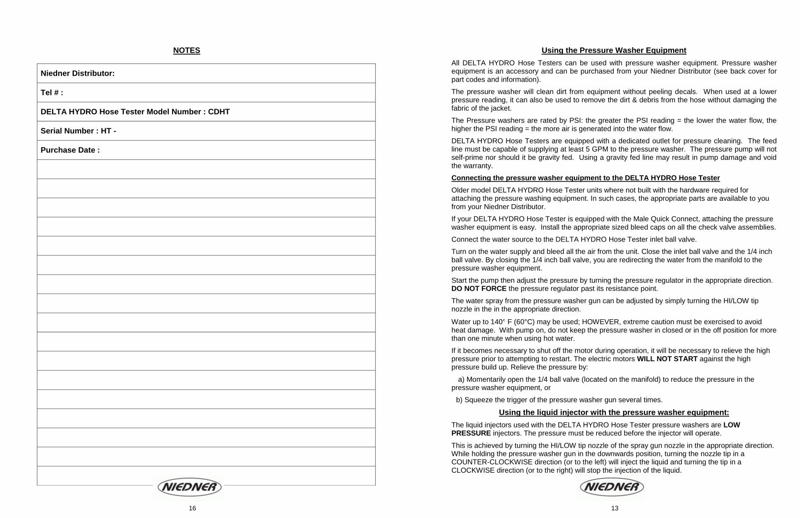
NOTES
Using the Pressure Washer Equipment
All DELTA HYDRO Hose Testers can be used with pressure washer equipment. Pressure washer equipment is an accessory and can be purchased from your Niedner Distributor (see back cover for part codes and information).
The pressure washer will clean dirt from equipment without peeling decals. When used at a lower pressure reading, it can also be used to remove the dirt & debris from the hose without damaging the fabric of the jacket.
The Pressure washers are rated by PSI: the greater the PSI reading = the lower the water flow, the higher the PSI reading = the more air is generated into the water flow.
DELTA HYDRO Hose Testers are equipped with a dedicated outlet for pressure cleaning. The feed line must be capable of supplying at least 5 GPM to the pressure washer. The pressure pump will not self-prime nor should it be gravity fed. Using a gravity fed line may result in pump damage and void the warranty.
Connecting the pressure washer equipment to the DELTA HYDRO Hose Tester
Older model DELTA HYDRO Hose Tester units where not built with the hardware required for attaching the pressure washing equipment. In such cases, the appropriate parts are available to you from your Niedner Distributor.
If your DELTA HYDRO Hose Tester is equipped with the Male Quick Connect, attaching the pressure washer equipment is easy. Install the appropriate sized bleed caps on all the check valve assemblies.
Connect the water source to the DELTA HYDRO Hose Tester inlet ball valve.
Turn on the water supply and bleed all the air from the unit. Close the inlet ball valve and the 1/4 inch ball valve. By closing the 1/4 inch ball valve, you are redirecting the water from the manifold to the pressure washer equipment.
Start the pump then adjust the pressure by turning the pressure regulator in the appropriate direction. DO NOT FORCE the pressure regulator past its resistance point.
The water spray from the pressure washer gun can be adjusted by simply turning the HI/LOW tip nozzle in the in the appropriate direction.
Water up to 140 F (60°C) may be used; HOWEVER, extreme caution must be exercised to avoid heat damage. With pump on, do not keep the pressure washer in closed or in the off position for more than one minute when using hot water.
If it becomes necessary to shut off the motor during operation, it will be necessary to relieve the high pressure prior to attempting to restart. The electric motors WILL NOT START against the high pressure build up. Relieve the pressure by:
a) Momentarily open the 1/4 ball valve (located on the manifold) to reduce the pressure in the pressure washer equipment, or
b) Squeeze the trigger of the pressure washer gun several times.
Using the liquid injector with the pressure washer equipment:
The liquid injectors used with the DELTA HYDRO Hose Tester pressure washers are LOW PRESSURE injectors. The pressure must be reduced before the injector will operate.
This is achieved by turning the HI/LOW tip nozzle of the spray gun nozzle in the appropriate direction. While holding the pressure washer gun in the downwards position, turning the nozzle tip in a COUNTER-CLOCKWISE direction (or to the left) will inject the liquid and turning the tip in a CLOCKWISE direction (or to the right) will stop the injection of the liquid.
Niedner Distributor:
Tel # :
DELTA HYDRO Hose Tester Model Number : CDHT
Serial Number : HT -
Purchase Date :
13 16

The principal of the liquid injector is to soap down the project, and then turn the nozzle back to high pressure for wash down. When first used, the nozzle may need to be cycled back and forth from high pressure to low pressure several times.
* * * THOROUGHLY RINSE ALL PRESSURE WASHER PARTS AFTER USE * * *
* * * NEVER RUN THE HOSE TESTER PUMP WITHOUT WATER * * *
Q& A DELTA HYDRO Hose Tester Trouble Shooting Q: Why does it take so long for the hose to pressurize? A: Pressurization time can be a time consuming process and should no be RUSHED!
It is normal for the pressurization procedure to take any where from 15 to 20 minutes or longer depending on the type of hose being testes, the diameter size, as well as the quantity of hose being tested.
However, it is also due in part to a designed safety feature. The hose is pressurized through a 1/4 inch high pressure hose which leads from the pump to the manifold. This small diameter hose restricts the volume of water which is transferred, which reduces the risk of a hose whipping around uncontrollably. ** Consider this: A pump from a Fire Truck unit can easily delivery anywhere from 250 GPM to 1000 GPM (depending on the make and model), where as the pump from the CDHT1500SS DELTA HYDRO Hose Tester delivers 3.2 GPM, The pump of the DELTA HYDRO Hose Tester is significantly smaller therefore the pressurization time will be longer and more time consuming.
However, by using the DELTA HYDRO Hose Tester (in accordance to this manual and the NFPA 1962 (2008 edition) guidelines,) the advantage is that you have not taken the Fire Truck out of service to perform your annual hose testing operations.
Q: Why won’t my DELTA HYDRO Hose Tester build up pressure? A: Double check the following pressurizing settings:
The inlet ball valve is CLOSED.
The water supply is TURNED ON.
The water supply is not restricted and it DOES have adequate pressure.
The 1/4” ball valve is OPEN.
There are NO LEAKS in the hose.
There is NO AIR remaining in the DELTA HYDRO Hose Tester unit. Additionally check the following on the DELTA HYDRO Hose Tester:
OPEN the 1/4 inch ball Valve (valve is to remain OPEN unless pressure washer equipment is being used).
REMOVE all the hose for the DELTA HYDRO Hose Tester.
Cap off all the check valves with the appropriate sized Bleep caps.
Turn the water supply ON.
CLOSE the main water supply inlet ball valve.
BLEED the AIR from the manifold.
With the Pressure regulator set at the minimum setting (full counter-clockwise), turn the pump on and SLOWLY raise the pressure.
Within a very few seconds, the pressure should build up to a 400 to 500 PSI range.
If the pressure gauge needle DOES NOT MOVE, STOP THE PUMP IMMEDIATLEY, and remove all the water from the DELTA HYDRO Hose Tester. You must replace the gauge before resuming the use of your DELTA HYDRO Hose Tester (Replacement parts can be ordered from your Niedner Distributor - see parts list for appropriate part number )
Checking the Pressure in the manifold: Use a line gauge system to check that there is adequate pressure in the manifold. To do so attach a separate pressure gauge to the appropriate sized adapter and attach this adapter to one of the TOP check valve outlets on the manifold of the DELTA HYRDO Hose Tester.
Cap off the remaining check valves with the appropriate sized bleed caps. Carefully repeat the above steps, this time observe the readings from BOTH pressure gauges.
If the pressure gauge on the line gauge shows a reading, but the pressure gauge on the DELTA HYDRO Hose Tester does not, its is likely that the pressure gauge on the DELTA HYDRO Hose Tester is faulty. DO NOT continue using the DELTA HYDRO Hose Tester until the faulty gauge has been replaced.
If the pressure builds up on either gauge, this means that the DELTA HYDRO Hose Tester is operating properly. There is one more step which can be taken to check the function of the pressure gauge.
** THE STEP BELOW MUST BE PERFORMED BY A TRAINED MECHANIC **
** WARNING: Improper replacement of the poppet valves could cause irreparable damage to the pump. It is imperative that this repair be completed by a trained mechanic. The pressure could be restricted due to the poppet valve located within the pump. If the poppet valves are clogged, broken, or dysfunctional, they will need to be replaced (replacement part available from your Niedner Distributor) before reusing the use of the DELTA HYDRO Hose Tester. Replacement of the Poppet Valves: To replace the poppet valves, unscrew each bolt from the pump. Carefully remove the poppet valve from its socket with a pair of needle nose pliers. Each poppet valve must be visually inspected and tested to ensure that the spring mechanism functions properly. If the spring mechanism move freely inside the poppet valve should when pushed inwards without applying too much force with the end of the needle nose pliers, it is functioning properly. If the spring is rusted or damaged, the entire poppet valve must be replaced. Once all the poppet valves are inspected, repaired or replaced re-assemble the pump by reversing the above steps.
Q: Why does the oil in the pump appear to be white / cloudy or milky? A: There are few reasons for the oil in the pump may appear this color. The first of which may be that
there is water leaking into the oil. This is likely caused by damaged / or warn packing rings. To order a replacement packing kit from your Niedner Distributor, you must provide the following: 1) The DELTA HYDRO Hose Tester serial number:
This number is on a black/metal tag, located on the Cart of the DELTA HYDRO Hose Tester. The serial number begins with: HT- 02XXXXXXX
2) Specify the model number and the manufacturing company of the Pump usually located on the underside of the pump. This is to ensure that the correct packing kit be ordered as manufacturing packing kits may differ.
If you are still having problems with your DELTA HYRDO Hose Tester, Please contact Niedner
1-800-567-2703 15 14