Dell Lifecycle Controller 2 Release 1.4.0 User's...
77
Dell Lifecycle Controller 2 Release 1.4.0 User's Guide
Transcript of Dell Lifecycle Controller 2 Release 1.4.0 User's...

Dell Lifecycle Controller 2Release 1.4.0 User's Guide

Notes, Cautions, and WarningsNOTE: A NOTE indicates important information that helps you make better use of your computer.
CAUTION: A CAUTION indicates either potential damage to hardware or loss of data and tells you how to avoid the problem.
WARNING: A WARNING indicates a potential for property damage, personal injury, or death.
Copyright © 2014 Dell Inc. All rights reserved. This product is protected by U.S. and international copyright and intellectual property laws. Dell™
and the Dell logo are trademarks of Dell Inc. in the United States and/or other jurisdictions. All other marks and names mentioned herein may be trademarks of their respective companies.
Mar - 2014
Rev. A00
Contents
1 Introduction..................................................................................................................... 7Why Use Lifecycle Controller.............................................................................................................................................. 7Benefits of Using iDRAC7 with Lifecycle Controller.............................................................................................................7What's New in this Release?.............................................................................................................................................. 8Key Features.......................................................................................................................................................................8Licensable Features in Lifecycle Controller..........................................................................................................................8Viewing iDRAC License Information....................................................................................................................................9Other Documents You May Need....................................................................................................................................... 9
Social Media Reference...............................................................................................................................................10Accessing Documents From Dell Support Site.................................................................................................................. 10Contacting Dell.................................................................................................................................................................. 11
2 Using Lifecycle Controller.............................................................................................. 12Launching Lifecycle Controller...........................................................................................................................................12
Automatic System Restore..........................................................................................................................................12Launch Messages, Causes, and Resolutions................................................................................................................13Enabling Lifecycle Controller....................................................................................................................................... 13Disabling Lifecycle Controller.......................................................................................................................................14Canceling Lifecycle Controller Actions.........................................................................................................................14
Using Lifecycle Controller for the First Time......................................................................................................................14Setting Up Lifecycle Controller....................................................................................................................................15
Lifecycle Controller Features.............................................................................................................................................16
3 Operating System Deployment...................................................................................... 17Installing Operating System............................................................................................................................................... 17Using Optional RAID Configuration....................................................................................................................................18Configuring RAID Using Operating System Deployment Wizard........................................................................................ 18Selecting Operating System.............................................................................................................................................. 18
Selecting an Operating System Available in the List.................................................................................................... 18Selecting Custom Operating System...........................................................................................................................19Selecting an Operating System Not Available in the List............................................................................................. 19
Driver Access.............................................................................................................................................................. 19Installing Operating System in Unattended Mode..............................................................................................................19Installing Operating System on iSCSI LUN and FCoE LUN............................................................................................... 20Rebooting System............................................................................................................................................................20
Post-reboot Scenarios................................................................................................................................................20
4 Monitor..........................................................................................................................21Hardware Inventory View and Export................................................................................................................................21About View and Export Current Inventory.........................................................................................................................21About View and Export Factory-Shipped Inventory...........................................................................................................21Viewing Hardware Inventory—Current or Factory-Shipped............................................................................................. 22
3

Exporting Hardware Inventory—Current or Factory-Shipped...........................................................................................22USB Drive...................................................................................................................................................................23Network Share........................................................................................................................................................... 23
Viewing or Exporting Hardware Inventory After Part Replacement.................................................................................. 23Viewing and Exporting Current Inventory After Resetting Lifecycle Controller................................................................. 24Lifecycle Log.................................................................................................................................................................... 24
Viewing Lifecycle Log History..................................................................................................................................... 24Exporting Lifecycle Log.............................................................................................................................................. 25Adding Work Note to Lifecycle Log............................................................................................................................ 26
5 Firmware Update...........................................................................................................27Download Methods.......................................................................................................................................................... 28Version Compatibility........................................................................................................................................................28Updating Firmware........................................................................................................................................................... 28
Selecting Type of Update And Update Source............................................................................................................29Using Single Component DUPs.................................................................................................................................. 32Selecting and Applying Updates................................................................................................................................. 32
Firmware Rollback............................................................................................................................................................ 33Rolling Back to Previous Firmware Versions................................................................................................................33
6 Configure...................................................................................................................... 35System Control Panel Access Options..............................................................................................................................35
Controlling Access to Front Panel...............................................................................................................................35Configuring iDRAC........................................................................................................................................................... 35Configuring System Time And Date..................................................................................................................................36Configuring vFlash SD Card............................................................................................................................................. 36
Enabling or Disabling vFlash........................................................................................................................................37Initializing vFlash.........................................................................................................................................................37
Configuring RAID..............................................................................................................................................................37Foreign Configuration Found...................................................................................................................................... 38Viewing Current RAID Configuration.......................................................................................................................... 38Selecting RAID Levels.................................................................................................................................................38Selecting Physical Disks............................................................................................................................................. 39Setting Virtual Disk Attributes.................................................................................................................................... 40Viewing Summary...................................................................................................................................................... 40
Configuring RAID Using Software RAID............................................................................................................................ 41Creating a Secure Virtual Disk on Series 8 Controller........................................................................................................ 41Key Encryption................................................................................................................................................................. 42
Applying the Local Key On RAID Controller.................................................................................................................42Local Key Encryption Mode..............................................................................................................................................43
Encrypting Unsecure Virtual Disks..............................................................................................................................43Rekey Controller With New Local Key........................................................................................................................ 43Removing Encryption and Deleting Data.................................................................................................................... 44
Breaking Mirrored Drives.................................................................................................................................................. 44System Setup-Advanced Hardware Configuration............................................................................................................44
Modifying Device Settings..........................................................................................................................................46
4

Collect System Inventory on Restart................................................................................................................................ 46Updating Server Inventory Information.......................................................................................................................47
Configuring Local FTP Server...........................................................................................................................................47FTP Authentication.....................................................................................................................................................47Requirements for a Local FTP Server......................................................................................................................... 47Copying Repository to a Local FTP Server from the Dell Server Updates DVD...........................................................47Using Dell Repository Manager to Create the Repository and Copy it to a Local FTP Server..................................... 47Accessing Updates on a Local FTP Server................................................................................................................. 47
Configuring Local USB Drive............................................................................................................................................ 48Copying Repository to a Local USB Drive from the Dell Server Updates DVD............................................................ 48Using Dell Repository Manager to Create the Repository and Copy it to a USB Drive................................................ 48
7 Maintain........................................................................................................................ 49Platform Restore.............................................................................................................................................................. 49
About Server Profile Backup Image............................................................................................................................49Supported Components............................................................................................................................................. 50
Backup Server Profile........................................................................................................................................................51Back Up Server Profile................................................................................................................................................51System or Feature Behavior During Backup................................................................................................................ 51
Export Server Profile........................................................................................................................................................52Exporting Server Profile to USB Drive or Network Share........................................................................................... 52
Import Server Profile........................................................................................................................................................ 52Importing Server Profile from a vFlash SD Card Network Share or USB Drive........................................................... 53Importing Server Profile After Motherboard Replacement......................................................................................... 55
Import Server License...................................................................................................................................................... 55Importing Server License from a Network Share or USB Drive.................................................................................. 55Importing iDRAC License from USB Drive.................................................................................................................. 56
Part Replacement Configuration...................................................................................................................................... 56Applying Firmware and Configuration to Replaced Parts............................................................................................ 56Supported Devices..................................................................................................................................................... 57
Lifecycle Controller Repair................................................................................................................................................57Repairing Lifecycle Controller..................................................................................................................................... 57
Deleting Configuration and Resetting Defaults................................................................................................................. 57Hardware Diagnostics...................................................................................................................................................... 58
Performing Hardware Diagnostics.............................................................................................................................. 58
8 Troubleshooting and Frequently Asked Questions......................................................... 59Error Messages................................................................................................................................................................ 59Frequently Asked Questions.............................................................................................................................................59
9 Lifecycle Log Schema....................................................................................................61
10 Easy-to-use System Component Names......................................................................62
11 Using The System Setup and Boot Manager................................................................ 65Choosing The System Boot Mode....................................................................................................................................65
5
Entering System Setup.....................................................................................................................................................66Responding To Error Messages.................................................................................................................................. 66Using The System Setup Navigation Keys..................................................................................................................66
System Setup Options..................................................................................................................................................... 66System Setup Main Screen........................................................................................................................................ 67System BIOS Screen.................................................................................................................................................. 67System Information Screen........................................................................................................................................ 67Memory Settings Screen............................................................................................................................................68Processor Settings Screen......................................................................................................................................... 68SATA Settings Screen................................................................................................................................................ 69Boot Settings Screen................................................................................................................................................. 70Integrated Devices Screen..........................................................................................................................................70Serial Communications Screen.................................................................................................................................... 71System Profile Settings Screen.................................................................................................................................. 72System Security Screen............................................................................................................................................. 72Miscellaneous Settings............................................................................................................................................... 73
System And Setup Password Features............................................................................................................................. 74Assigning A System And/Or Setup Password.............................................................................................................74Deleting Or Changing An Existing System And/Or Setup Password...........................................................................75Using Your System Password To Secure Your System................................................................................................ 75Operating With A Setup Password Enabled................................................................................................................75
Entering The UEFI Boot Manager.....................................................................................................................................76Using The Boot Manager Navigation Keys..................................................................................................................76Boot Manager Screen.................................................................................................................................................76UEFI Boot Menu......................................................................................................................................................... 77
Embedded System Management......................................................................................................................................77iDRAC Settings Utility.......................................................................................................................................................77
Entering The iDRAC Settings Utility............................................................................................................................77
6
1IntroductionThe Dell Lifecycle Controller provides advanced embedded systems management to perform systems management tasks such as deploy, configure, update, maintain, and diagnose through a graphical user interface. It is delivered as part of iDRAC7 out-of-band solution and embedded Unified Extensible Firmware Interface (UEFI) applications in the latest Dell servers. The iDRAC7 works with the UEFI firmware to access and manage every aspect of the hardware, including component and subsystem management that is beyond the traditional Baseboard Management Controller (BMC) capabilities.
NOTE: The UEFI environment provides the local console interface and the infrastructure for locally-managed system components.
The Lifecycle Controller has the following components:
• GUI–based Lifecycle Controller:
– Is an embedded configuration utility that reside on an embedded flash memory card.
– Is similar to the BIOS utility that is started during the boot sequence, and can function in a preoperating system environment.
– Enable systems and storage management tasks from an embedded environment throughout the system’s life cycle.
• Remote Services (WS-Management) simplifies end-to-end server lifecycle management using the one-to-many method. It interfaces for remote deployment integrated with Dell OpenManage Essentials and partner consoles. For more information about Remote Services features, see Dell Lifecycle Controller Remote Services Quick Start Guide.
Why Use Lifecycle ControllerSystems management is typically a key part of an administrator’s role. Being able to install an operating system, updating firmware for function and policies requirements, configuring devices and getting the most out of an IT network are integral aspects of this role. Prior to the release of Lifecycle Controller, an administrator had to use tools such as Dell OpenManage Server Administrator (DSA), Dell Systems Build Update Utility (SBUU), and Dell Deployment Toolkit (DTK) shipped on multiple CDs or DVD. Maintaining and using the multiple disks in their many versions was time-consuming for the administrator.
To resolve these problems, Dell provides the Lifecycle Controller, a flash chip embedded on the system with the Lifecycle Controller application. The Lifecycle Controller allows the IT administrator to do away with media altogether, allowing operating system deployment with locally-embedded driver repositories, firmware updates, hardware configuration, and platform-specific diagnostic routines. As Lifecycle Controller is available even when the operating system is not functional or even installed, it allows added flexibility in provisioning the system and customizing to suit your requirements. As the tool is integrated and embedded, formatting or reinstalling the operating system does not remove the tool, thus saving significant time and money.
Benefits of Using iDRAC7 with Lifecycle ControllerThe benefits include:
• Increased Availability — Early notification of potential or actual failures that help prevent a server failure or reduce recovery time after failure.
• Improved Productivity and Lower Total Cost of Ownership (TCO) — Extending the reach of administrators to larger numbers of distant servers can make IT staff more productive while driving down operational costs such as travel.
• Secure Environment — By providing secure access to remote servers, administrators can perform critical management functions, while maintaining server and network security.
7
• Enhanced Embedded Management through Lifecycle Controller – Lifecycle Controller provides deployment and simplified serviceability through Lifecycle Controller GUI for local deployment and Remote Services (WS-Management) interfaces for remote deployment integrated with Dell OpenManage Essentials and partner consoles.
For more information on iDRAC7, see Integrated Dell Remote Access Controller User’s Guide available at dell.com/support/manuals.
What's New in this Release?The new features for this release are:
• Added support for R220, FC420, FC620, R920, and FM120 servers.
• Support for the new operating systems. For a list of supported operating systems, contact your service provider.
• Support for the Emulex NICs: D6T93, RFPC9, YGW92, KYKT7, and JJPC0.
• Support for Samsung Solid State Drive (SSD).
Key FeaturesThe key features of Lifecycle Controller are:
• Provisioning — Entire pre-operating system configuration from a unified interface.
• Deploying — Simplified operating system installation with embedded drivers on the Lifecycle Controller. Installing an OS using the unattended installation mode for Windows-based OS.
• Download drivers for operating system installation from one of the following sources:
– Dell FTP website at ftp.dell.com
– Dell Lifecycle Controller OS Driver Packs DVD for Windows and Linux
• Patching or Updating — Operating system agnostic, and reduced maintenance downtime with direct access to updates from ftp.dell.com. It simplifies firmware updates by maintaining a working version for rollback.
• Servicing — Continuous availability of diagnostics without depending on a hard disk drive. Ability to flash firmware automatically, while replacing field-replaceable components such as a Dell PowerEdge storage controller, NIC, and power supply unit. Support for VLAN in network configuration.
• Reset the system to factory default — Deletes the current iDRAC settings and resets iDRAC to factory default settings. It also deletes lifecycle logs, factory-shipped inventory, driver packs, and diagnostics information on the managed node, and deletes all the user-settings and configurations.
• Security — Supports local key encryption.
• Restoring Platform — Backup the server profile (including RAID configuration) and restore the server to a previously-known state. Importing a server license, updating firmware, and restoring system configuration in case of motherboard replacement.
• Lifecycle logs for troubleshooting
• Hardware inventory — Provides information about both the current and factory system configuration.
• Supports H730P controller on the Equinox server.
Licensable Features in Lifecycle ControllerLifecycle Controller features are available based on the type of license (Basic Management, iDRAC7 Express, iDRAC7 Express for Blades, or iDRAC7 Enterprise) that you purchase. Only licensed features are available in the Lifecycle Controller Web interface. For more information about managing licenses, see the iDRAC7 User’s Guide. The following table lists the Lifecycle Controller features available based on the license purchased.
8

Feature Base Management with IPMI
iDRAC7 Express iDRAC7 Express for Blades
iDRAC7 Enterprise
Firmware Update Yes Yes Yes Yes
Operating System Deployment
Yes Yes Yes Yes
Device Configuration Yes Yes Yes Yes
Diagnostics Yes Yes Yes Yes
Server Profile Backup and Export
— — — Yes
Server Profile Import Yes Yes Yes Yes
Part Replacement — Yes Yes Yes
Local Updates Yes Yes Yes Yes
Driver Packs Yes Yes Yes Yes
Hardware Inventory Yes Yes Yes Yes
Remote Services (through WS-MAN)
- Yes Yes Yes
Viewing iDRAC License InformationAfter you open the Lifecycle Controller GUI page, you can view details about the iDRAC installed on a server. You can view the iDRAC license information on all the pages of Lifecycle Controller by clicking the About symbol in the upper-right corner of Lifecycle Controller GUI. To view information about an iDRAC license:
1. On any page of Lifecycle Controller, click About in the upper-right corner. On the About page:
NOTE: If a license is not installed on the server, information such as entitlement ID and license expiration are not displayed.
2. To read through the Release Notes, click View Release Notes.
3. To view detailed information about iDRAC, click License Information.
On the iDRAC License Report page, the following information is displayed.
Device ID Indicates the service tag of the server on which an iDRAC is installed.
License • Entitlement ID: Indicates a unique ID provided by the manufacturer.
• Status: Indicates the status of the installed license. The different licenses statuses are: a. b. c.
• Description: Indicates the license type along with a unique ID.
• License Type: Indicates the type of license of the device. For example, Evaluation, Express, or Enterprise.
• Expiration: Indicates the date and time on which the license expires. The format: YYYY-MMQDD T HQMQM
Other Documents You May NeedIn addition to this guide, you can access the following guides available at dell.com/support/manuals.
• The Lifecycle Controller Online Help provides detailed information about the fields available on the GUI and the descriptions for the same. To view the online help information, click Help in the upper-right corner of all Lifecycle Controller pages, or press <F1>.
9

• The Lifecycle Controller Release Notes is available from within the product. To read through the Release Notes within Lifecycle Controller, click the About symbol, and then click View Release Notes. A Web version is also given to provide last-minute updates to the system or documentation or advanced technical reference material intended for experienced users or technicians.
• The Dell iDRAC7 Licensing Whitepaper - Differences between iDRAC6 and iDRAC7 at http://en.community.dell.com/techcenter/extras/m/white_papers/20067892.aspx. This document provides an overview of iDRAC7 digital licensing and how it is different from iDRAC6. Understanding iDRAC7 Express and Enterprise Value Offerings
• The Dell Lifecycle Controller-Remote Services Quick Start Guide provides information about using Remote Services.
• The Systems Management Overview Guide provides brief information about the various software available to perform systems management tasks.
• The iDRAC7 Overview and Feature Guide provides information about iDRAC7, its licensable features, and license upgrade options.
• The Integrated Dell Remote Access Controller 7 (iDRAC7) User’s Guide provides information about configuring and using an iDRAC7 for rack, tower, and blade servers to remotely manage and monitor your system and its shared resources through a network.
• The Dell Repository Manager User Guide provides information about creating customized bundles and repositories comprised of Dell Update Packages (DUPs), for systems running supported Microsoft Windows operating systems.
• The Lifecycle Controller Supported Dell Systems and Operating Systems section in the Dell Systems Software Support Matrix provides the list of Dell systems and operating systems that you can deploy on the target systems.
• The PERC H710, H710P, and H810 Technical Guidebook for specification and configuration-related information about the PERC H710, H710P, and H810 controllers.
• The Glossary provides information about the terms used in this document.
• The Dell OpenManage Server Update Utility User's Guide provides information about using the DVD–based application for identifying and applying updates to the system.
The following system documents are available to provide more information:
• The safety instructions that came with your system provide important safety and regulatory information. For additional regulatory information, see the Regulatory Compliance home page at dell.com/regulatory_compliance. Warranty information may be included within this document or as a separate document.
• The Rack Installation Instructions included with your rack solution describe how to install your system into a rack.
• The Getting Started Guide provides an overview of system features, setting up your system, and technical specifications.
• The Owner’s Manual provides information about system features and describes how to troubleshoot the system and install or replace system components.
• Lifecycle Controller Web Services Interface Guide–Windows and Linux
Social Media Reference
To know more about the product, best practices, and information about Dell solutions and services, you can access the social media platforms such as Dell TechCenter and YouTube. You can access blogs, forums, white papers, how-to videos, and so on from the Lifecycle Controller wiki page at www.delltechcenter.com/lc.
For Lifecycle Controller documents and other related firmware documents, see www.dell.com/esmmanuals.
Accessing Documents From Dell Support SiteYou can access the required documents in one of the following ways:
• From the following links:
– For all Systems Management documents — dell.com/softwaresecuritymanuals
– For Enterprise Systems Management documents — dell.com/openmanagemanuals
– For Remote Enterprise Systems Management documents — dell.com/esmmanuals
– For Serviceability Tools documents — dell.com/serviceabilitytools
– For Client Systems Management documents — dell.com/OMConnectionsClient
– For OpenManage Connections Enterprise Systems Management documents — dell.com/OMConnectionsEnterpriseSystemsManagement
10

– For OpenManage Connections Client Systems Management documents — dell.com/OMConnectionsClient
• From Dell Support site as follows:
– Go to dell.com/support/manuals.
– In the Tell us about your Dell system section, under No, select Choose from a list of all Dell products and click Continue.
– In the Select your product type section, click Software and Security.
– In the Choose your Dell Software section, click the required link from the following:
* Client System Management
* Enterprise System Management
* Remote Enterprise System Management
* Serviceability Tools
– To view the document, click the required product version.
• Using search engines as follows:
– Type the name and version of the document in the Search box.
Contacting DellNOTE: If you do not have an active Internet connection, you can find contact information on your purchase invoice, packing slip, bill, or Dell product catalog.
Dell provides several online and telephone-based support and service options. Availability varies by country and product, and some services may not be available in your area. To contact Dell for sales, technical support, or customer service issues:
1. Visit dell.com/support
2. Select your support category.
3. Verify your country or region in the Choose a Country/Region drop-down menu at the top of page.
4. Select the appropriate service or support link based on your need.
11

2Using Lifecycle ControllerThis section provides information about launching Lifecycle Controller, enabling or disabling it, and launching it for the first time. Before using Lifecycle Controller, make sure that the network and iDRAC7 are configured. For more information, see iDRAC7 User’s Guide.
Launching Lifecycle ControllerTo start Lifecycle Controller during the system start, press the<F10>key within 10 seconds after the manufacturer's or service provider’s logo is displayed. When Lifecycle Controller is started for the first time, it displays Settings wizard that allows you to configure the preferred language and network settings.
NOTE: If the system does not enter Lifecycle Controller, see Launch Messages Causes and Resolutions.
Related links
Setting Up Lifecycle Controller
Automatic System Restore
Use this feature to automatically restore the system configuration after replacing a motherboard. The system configuration must be backed up on a vFlash SD card.
A message is displayed asking you to either import server profile from a vFlash SD Card or manually type the Service Tag–related information. The Automatic system restore from vflash SD card option is grayed out if:
• A vFlash SD card is not present in the system.
• A vFlash SD card is present, but the system configuration backup file is not stored on the card.
However, if a backup file is present on a USB drive, NFS, or CIFS, click Cancel, and then restore the system configuration using the Platform Restore feature. For more information about backing up a server profile and restoring a system configuration, see Backup Server Profile and Platform Restore.
Restoring a Server Profile from vFlash Backup
When you have a backup on a vFlash SD card, but a service tag is not available:
1. Lifecycle Controller automatically displays the following message on the home page. Click Yes.
Do you want to restore the service tag?2. In the Restore Service Tag dialog box:
• To import a server profile that is stored on a vFlash SD card, click Import Server Profile. For more information about importing a server profile, see Import Server Profile.
NOTE: To import a server profile, you must have an Enterprise license and administrator-level privileges.
• To manually enter a service tag, click Manually Configure Service Tag. On the Service Tag Settings page, type the service tag, and then click OK.
NOTE: Before you restore the system configuration, make sure that the latest version of BIOS is installed.
12

Restoring System Config by Manually Entering ServiceTag
When you do not have a backup on a vFlash SD card:
1. Lifecycle Controller automatically displays the following message on the home page. Click Yes.
Unable to Detect Service Tag. Do you want to enter the service tag label?NOTE: Before you restore the system configuration, make sure that the latest version of BIOS is installed.
2. On the Service Tag Settings page, type the service tag, and then click Apply.
Launch Messages, Causes, and Resolutions
The table lists the messages that appear during system startup, and their appropriate cause and resolution.
Message Cause Resolution
Lifecycle Controller disabled • The system is turned on or restarted while iDRAC is initializing. This occurs if:
– The system is turned on immediately after AC is applied to the system.
– The system is restarted immediately after resetting iDRAC.
• Lifecycle Controller is manually disabled.
Wait for a minute after resetting iDRAC to restart the system, so that iDRAC initializes.
Lifecycle Controller Update Required The embedded device that stores the product may contain corrupted data.
If an operating system is not installed on the system, run the Lifecycle Controller repair package using iDRAC.
Update the product using Lifecycle Controller Dell Update Package (DUP). For more information about DUPs, see the Dell Update Packages User’s Guide available at dell.com/support/manuals.
For more information about recovering Lifecycle Controller from the Lifecycle Controller Update Required mode, see the Recovery from ‘Lifecycle Controller Update Required’ white paper available at delltechcenter.com/lc.
Lifecycle Controller not available Another process is currently using iDRAC. Wait for 30 minutes for the current process to complete, restart the system, and then retry.
Lifecycle Controller in Recovery Mode (3-strike policy)
Ungracefully exit Lifecycle Controller for 3 consecutive times.
Update Lifecycle Controller using Lifecycle Controller repair package through iDRAC.
Related links
Disabling Lifecycle Controller
Repairing Lifecycle Controller
Enabling Lifecycle Controller
To boot into Lifecycle Controller during startup:
1. Press the<F2> key within five seconds after system start-up.
The System Setup Main Menu page is displayed.
2. Click iDRAC Settings.
13

The iDRAC Settings page is displayed.
3. Click Lifecycle Controller.
4. Select Enabled.
5. On the System Setup Main Menu page, click Finish to save the settings.
6. Click Yes to restart the system.
Disabling Lifecycle Controller
To prevent the system from entering Lifecycle Controller during startup:
1. Press <F2> within five seconds after system start-up.
The System Setup Main Menu page is displayed.
2. Click iDRAC Settings.
The iDRAC Settings page is displayed.
3. Click Lifecycle Controller.
4. Under Lifecycle Controller, select Disabled.
5. On the System Setup Main Menu page, click Finish to save the settings.
6. Click Yes to restart the system.
Canceling Lifecycle Controller Actions
If Lifecycle Controller causes the system to restart twice, cancel the Lifecycle Controller actions. However, if Lifecycle Controller causes the system to restart the third time, the message LC Update required is displayed, and you must use Lifecycle Controller repair package to recover Lifecycle Controller.
CAUTION: This action cancels all tasks that are being performed by Lifecycle Controller. It is recommended that you cancel the Lifecycle Controller actions only when absolutely necessary.
1. Press <F2> within five seconds after system start-up.
The System Setup Main Menu page is displayed.
2. In the System Setup Main Menu page, click iDRAC Settings.
The iDRAC Settings page is displayed.
3. Click Lifecycle Controller.
4. Under Cancel Lifecycle Controller Actions, select Yes.
5. On the System Setup Main Menu page, click Finish to save the settings.
6. Click Yes to restart the system.
Using Lifecycle Controller for the First TimeAfter you start Lifecycle Controller for the first time, by default the Settings → Language and Keyboard page is launched. However, the Home page is displayed after subsequent launches.
1. By default, the Language and Keyboard Layout are English and United States. To change language and keyboard layout, select the Language and Keyboard Layout, and then click Next.
The Network Settings page is displayed.
2. Configure the network settings, and then click Finish. It is recommended that you open Firmware Update page, apply the required updates.
Related links
Setting Up Lifecycle Controller
Automatic System Restore
Updating Firmware
14
Setting Up Lifecycle Controller
Use Settings wizard to specify the language, keyboard layout, and network settings for Lifecycle Controller only. This does not change the system or other application settings.
Specifying Language and Keyboard Type
1. In the left pane, click Settings.
2. In the right pane, click Language and Keyboard. Use the up-arrow and down-arrow keys to select the options.
• From the Language drop-down menu, select the language.
• From the Keyboard Type drop‑down menu, select the keyboard type.
3. Click Finish to save the new settings.
Configuring Network Settings for a NIC
1. In the left pane, click Settings.
2. In the right pane, click Network Settings.
3. From the NIC Card drop-down menu, select the NIC card that you want to configure. You can use only one NIC at a time to communicate with the network.
4. From the IP Address Source drop-down menu, select one of the following options:
NOTE: The IP Address Source function supports only IPv4.
IP Address Properties
• No Configuration — Select to indicate that NIC must not be configured.
• DHCP — Select to indicate that the NIC must be configured by using an IP address from a DHCP server.
• Static IP — Select to type static IP address. Type these IP address properties: IP Address, Subnet Mask, Default Gateway, DNS Address. If you do not have this information, contact your network administrator.
Lifecycle Controller VLAN Properties
You can configure the VLAN settings of a Lifecycle Controller NIC.
NOTE: For more information about the VLAN feature, read through the Configuring VLAN Settings in Lifecycle Controller for Dell PowerEdge Servers white paper available at delltechcenter.com/lc.
You can either enable or disable this settings. For more information about the fields in this section, click the Help link in the upper-right corner of the Network Settings page.
5. Click Finish to save the settings.
NOTE: If Lifecycle Controller Settings are not correctly configured, an error message is displayed.
NOTE: If you are unable to connect to a network, verify the settings. For more information about correct network settings, contact your network administrator.
If DHCP is enabled, a DHCP IP address is displayed on the Network Settings page.
Accessing Help
Each Lifecycle Controller screen has a help associated with it. Press <F1> or click Help (in the upper-right corner) to view the help information about the features available on a page.
Viewing Release Notes
1. To view the Release Notes, on all pages of Lifecycle Controller (except the help page of a topic that you view by pressing <F1>), click About. The About page is displayed.
2. Click View Release Notes.
15
Lifecycle Controller FeaturesThis section provides a brief description about the Lifecycle Controller features and helps know about the wizards to use Lifecycle Controller most effectively. Each feature is a wizard in Lifecycle Controller, which supports the following features:
• Home — Navigate back to the Home page.
• Lifecycle Log — View and export lifecycle log, and add a work note to lifecycle log.
• Firmware Update — Apply updates or perform firmware rollback for the system components, and view the firmware version available in a server.
• Hardware Configuration — Configure system devices, view, and export hardware inventory of a system.
• OS Deployment — Install an operating system in the manual mode or an unattended mode by using an 'answer' file.
• Platform Restore — Backup, export, and restore system profile. Import iDRAC license from Lifecycle Controller GUI.
• Hardware Diagnostics — Perform diagnostics to validate the memory, I/O devices, CPU, physical disks, and other peripherals.
• Settings — Specify the language, keyboard layout, and network settings while using Lifecycle Controller.
• System Setup — Configure settings for devices or components such as iDRAC, BIOS, RAID, and NIC.
Related links
Lifecycle Log
Firmware Update
Firmware Rollback
Hardware Inventory View and Export
Configure
Operating System Deployment
Platform Restore
Hardware Diagnostics
Setting Up Lifecycle Controller
Using The System Setup and Boot Manager
Import Server License
Installing Operating System in Unattended Mode
Viewing iDRAC License Information
Restoring a Server Profile from vFlash Backup
16

3Operating System DeploymentUsing the operating system deployment wizard, you can deploy various custom and standard operating systems on the managed system and configure a RAID during installation.
Related links
Installing Operating System
Installing Operating System in Unattended Mode
Installing Operating SystemBefore installing an operating system (OS), make sure that the following prerequisites are met:
• Optical DVD drive, or a virtual media (ISO image) is connected virtually to a server.
• Software RAID or PERC controller is installed with the latest firmware, and at least two hard disk drives are available for creating the virtual disk. For more information about the supported controllers and related firmware, see operating system documentation.
• Hard disk drive is connected.
• Virtual media is connected. For more information, see the iDRAC User’s Guide.
NOTE: S110 controller supports only SATA disk drives for which a minimum of two hard disk disks are required.
NOTE: You can install the operating system on a non-RAID hard disk drive, which is connected to a PERC H310 controller.
To install an operating system:
1. Start Lifecycle Controller by turning on the system, and then pressing the <F10> key within 10 seconds after the Dell logo is displayed.
2. In the left pane, click OS Deployment.
3. In the right pane, click Deploy OS and select one of the following:
• Configure RAID First: Optional, if an already-connected virtual disk is present. Else,click Go Directly to OS Deployment. Click to configure a RAID connected to the server. For information about configuring a RAID, see Using Optional RAID Configuration.
• Go Directly to OS Deployment: Click to install an operating system in manual mode or unattended installation mode.
4. Select the operating system from the list, select whether you want to install an OS manually or by using the Unattended OS installation. For more information about the unattended OS installation feature, see Installing OS in Unattended Mode.
NOTE: Currently, you can install only Windows OSs by using the unattended OS installation feature.
NOTE: A detailed procedure about installing an OS using the unattended installation feature of Lifecycle Controller is discussed in the white paper Unattended Installation of Operating Systems from Lifecycle Controller on Dell PowerEdge Servers available at delltechcenter.com/lc.
5. Select the deployment mode, insert the operating system media, and then complete the remaining tasks.
NOTE: If you select an operating system that supports UEFI boot mode, BIOS and UEFI options are provided for selecting the boot mode.
6. Restart the system.
The operating system is automatically installed on the selected virtual disk.
17

Related links
Selecting Operating System
Rebooting System
Using Optional RAID Configuration
Using Optional RAID ConfigurationWhen you install an operating system, you can do one of the following:
• Deploy the operating system without configuring RAID.
• Configure the hard disk drives using the optional RAID configuration wizard and deploy the operating system.
Alternatively, you can configure RAID through the RAID configuration page from the Hardware Configuration → Configuration Wizards → RAID Configuration.
Configuring RAID Using Operating System Deployment WizardTo configure a RAID using the OS Deployment page:
NOTE: If the system has a RAID controller, you can configure a virtual disk as the boot device.
1. In the left pane of the Home page, click OS Deployment, and then click Deploy OS in the right pane.
2. On the Deploy OS page, click Configure RAID First, and then click Next.
On the RAID Configuration page, all the storage controllers available for configuration are displayed.
3. Select a storage controller.
The RAID Configuration options are displayed.
4. Using the on-screen instructions, complete RAID setting tasks, and then click Finish.
The RAID configuration is applied to the virtual disks, and the Select an Operating System page is displayed.
Selecting Operating SystemYou can select an operating system based on its availability and user preference. Perform any one of the following actions:
• Selecting an Operating System Available in the List
• Selecting Custom Operating System
• Selecting an Operating System Not Available in the List
Selecting an Operating System Available in the List
To install an operating system that is available in the list:
1. From the list, select the required operating system, and then click Next.
The drivers are extracted to the OEMDRV directory, and Lifecycle Controller prompts you to insert the operating system installation media.
2. Lifecycle Controller displays two installation modes — UEFI or BIOS. Select one of the options and click Next.
If the selected operating system does not support the UEFI mode, the UEFI option is grayed-out. However, if the operating system that is being installed has partial support for UEFI–based installation, it may fail and you may not be able to boot into the operating system. Make sure to see the operating system documentation before installing the operating system in UEFI mode. Else, set the boot mode to BIOS and install the operating system.
3. Insert the standard operating system installation media when prompted, and then click Next. Lifecycle Controller validates the media.
4. If the standard operating system installation media is validated, continue the installation. Else, insert the correct media and click Next.
18

The Reboot the System page is displayed.
Selecting Custom Operating System
To install a custom operating system:
1. From the list, select the required custom operating system and click Next.
The drivers are extracted into the local directory and Lifecycle Controller prompts you to insert the operating system installation media.
2. Insert the custom operating system media with all the operating system components that are specific to your requirements, and then click Next.
3. If the validation check is unsuccessful, the following message is displayed:
The selected media doesn’t match the standard media certification of the OS <name of the selected operating system>
4. Click Yes to continue; else, No to insert a different media and retry.
The Reboot System page is displayed.
Selecting an Operating System Not Available in the List
To install an operating system that is not available in the list:
1. Select the option Any Other Operating System, and then click Next.
No drivers are extracted. Therefore, prepare the drivers for the required operating system.
2. Insert the operating system installation media with all the operating system components that are specific to your requirements and click Next.
NOTE: Lifecycle Controller does not validate the media.
The Reboot the System page is displayed
Related links
Rebooting System
Driver Access
Driver Access
Lifecycle Controller provides a local repository for drivers that are required for installing the operating system. On the basis of operating system being installed, the OS Deployment wizard extracts these drivers and copies them to a temporary directory on the managed system. These files are deleted after an 18-hour period or when you press <F10> to either cancel operating system installation or reenter Lifecycle Controller after restarting the system, or when an AC power-cycle operation is performed.
NOTE: Although, Lifecycle Controller has embedded drivers that are factory-installed, there are latest drivers available. Before installing the operating system, update the latest Lifecycle Controller driver packs to make sure that the latest drivers are available on the server.
Installing Operating System in Unattended Mode
An unattended installation is a scripted OS installation process that automatically runs the Windows setup on the server by using a config file. Unattended installation helps you install an OS without human intervention, and at a faster rate.
To install an operating system using the unattended installation mode.
NOTE: You must select only an Microsoft Windows operating system, because only the Windows operating system are currently supported. If you select an OS other than Windows, the Unattended Install option will be grayed out.
1. To install an OS, select one of the following options.
19

• Unattended Install
• Manual Install
NOTE: Both the options are displayed only if the OS is compatible for an unattended installation. Else, the Unattended Install option is grayed out, and only the Manual Install option is displayed.
2. On the Select Installation Mode pages, select or enter appropriate data to import an answer file and then click Next. For information about the fields available on these pages, see the online help file by clicking the Help icon in the upper-right corner of Lifecycle Controller GUI. For information about creating an answer file (configuration file) that supports unattended installation of a Windows OS, see the white paper Unattended Installation of Operating Systems from Lifecycle Controller on Dell PowerEdge Servers available at delltechcenter.com/lc.
3. Insert an OS media, and then click Next.
Installing Operating System on iSCSI LUN and FCoE LUNYou can install an operating system on an iSCSI LUN and FCoE LUN by using the System Setup page. A detailed procedure about installing is discussed in the white paper Deploying Operating System on iSCSI & FCOE LUN available at delltechcenter.com/lc.
Rebooting SystemClick Finish to reboot the system and continue with the operating system installation. The system boots to the operating system installation media.
Post-reboot Scenarios
The following table lists the post-reboot scenarios, its user actions, and impact.
Scenario User Action and Impact
During POST, the system prompts you to press a key to boot into the operating system installation media
Press any key to begin the operating system installation; else, the system boots to the hard disk drive and not the operating system installation media.
Operating system installation is interrupted and the system restars before the installation is completed.
The system prompts you to press a key to boot from the operating system installation media.
Want to cancel operating system installation. Press <F10>.
NOTE: Pressing <F10> at any point during the installation process, or while restarting, causes any drivers provided by the OS Deployment wizard to be removed.
During the 18-hour period when drivers are extracted to a temporary location after the operating system is installed, you cannot update the component firmware by using a DUP. If you attempt a DUP update through the operating system during this time period, the DUP displays a message that another session is active.
Lifecycle Controller does not allow this after the operating system installation. However, if you disconnect the power supply to the managed system, the OEMDRV directory is erased.
20

4MonitorUsing Lifecycle Controller, you can monitor the hardware inventory and events in the system throughout its lifecycle.
Hardware Inventory View and ExportLifecycle Controller provides the following wizards to manage the system inventory:
• View Current Inventory
• Export Current Inventory
• View Factory Shipped Inventory
• Export Factory Shipped Inventory
• Collect System Inventory on Restart
About View and Export Current InventoryYou can view information about the currently-installed hardware components that are internal to the system chassis and the configuration for each component. The table lists all the currently-installed hardware components (for example, fans, PCI devices, NICs, DIMMs, PSU, and so on), and their properties and values. You can export this information to a compressed file and then to a USB drive or network share. The XML File is saved in the following format: HardwareInventory_<servicetag>_<timestamp>.xml
For more information about the easy-to-use names of the hardware components, see Easy-to-use System Component Names.
NOTE: Incorrect inventory data is displayed or exported after performing Delete Configuration and Reset Defaults. For viewing the correct inventory data, see Viewing and Exporting Current Inventory After Resetting Lifecycle Controller.
Related links
Viewing Hardware Inventory—Current or Factory-Shipped
Exporting Hardware Inventory—Current or Factory-Shipped
Viewing or Exporting Hardware Inventory After Part Replacement
About View and Export Factory-Shipped InventoryYou can view information about the factory-installed hardware components and their configuration. You can export this information in an XML format to a USB drive, network share, or both the locations. The XML file is saved in this format: FactoryShippedHWInventory_<servicetag>.xml.
For more information about the easy-to-use names of the hardware components, see Easy-to-use System Component Names.
NOTE: View and export factory-shipped inventory feature is grayed out if the Delete Configuration and Reset Defaults option is selected, which permanently deletes the factory-shipped inventory.
Related links
Viewing Hardware Inventory—Current or Factory-Shipped
Exporting Hardware Inventory—Current or Factory-Shipped
21
Viewing Hardware Inventory—Current or Factory-ShippedTo view the currently-installed or factory-installed hardware components and their configuration details:
NOTE: For factory-shipped inventory, the state of few parameters for the installed components is displayed as Unknown.
1. In the left pane, click Hardware Configuration.
2. In the right pane, click Hardware Inventory.
3. To view the current- or factory-shipped inventory, click View Current Inventory or View Factory Shipped Inventory respectively.
NOTE: Lifecycle Controller does not provide the driver version for the RAID controller. To view the driver version, use iDRAC7, OpenManage Server Administrator Storage Service, or any other third-party storage management application.
4. On the View Current Hardware Inventory page, a list of hardware components is displayed. To filter components on the basis of hardware components, select from the Filter by Hardware Component drop-down menu. The FQDD property of a component is also listed along with other properties of a hardware component.
NOTE: You can filter data even on the basis of a FQDD property of the hardware component. By default, the FQDD DeviceDescription property value of a component is displayed for every hardware component listed.
Related links
About View and Export Current Inventory
About View and Export Factory-Shipped Inventory
Exporting Hardware Inventory—Current or Factory-ShippedBefore exporting the currently-installed or factory-installed hardware components and their configuration, make sure the following prerequisites are met:
• If you use the network share (shared folder), configure the Network Settings. For more information, see Setting Up Lifecycle Controller.
• If you are storing the exported file in a USB drive, make sure that a USB drive is connected to the managed-system.
To export the current or factory-shipped hardware inventory:
NOTE: For factory-shipped inventory, the state of few parameters for the installed components displays Unknown.
1. In the left pane, click Hardware Configuration.
2. In the right pane, click Hardware Inventory.
3. Click Export Current Inventory or Export Factory Shipped Hardware Inventory.
4. If you are exporting the inventory to a local USB drive, select USB Drive. If you are exporting the file to a shared folder on a network, select Network Share,
5. To verify whether or not Lifecycle Controller is able to connect to the IP address that you entered, click Test Network Connection. By default, Lifecycle Controller PINGs the Gateway IP, DNS server IP, and the host IP.
NOTE: If the DNS is not able to resolve the domain name, Lifecycle Controller cannot ping to the domain name and does not display its IP address. Make sure that the DNS–related issue is resolved, and then retry the operation.
6. Click Finish to export the inventory.
The HardwareInventory _<servicetag>_<timestamp>.xml or FactoryShippedHWInventory_<servicetag>.xml file is copied to the specified location. For the current inventory, the time stamp is in the format yyyy-mm-ddthh:mm:ss, where ‘t’ indicates time.
22

Related links
About View and Export Current Inventory
About View and Export Factory-Shipped Inventory
USB Drive
Network Share
USB Drive
To export hardware-related inventory to a USB drive:
1. From the Select Device drop-down menu, select a USB drive.
2. In the File Path box, type a valid directory or sub-directory path on the device. For example, 2011\Nov. If the path is not provided, the file is stored in the root location of the device.
NOTE: Lifecycle Controller allows 256 characters in a path, and does not support special characters such as :, *, ?, ", <, >, |, #, %, and ^ in folder names.
Network Share
To export to a Network Share, select CIFS or NFS and type the required details.
Related links
CIFS
NFS
CIFS
For CIFS, type the following details:
• Share Name — Type the path to the shared folder to export the file. For example, type \\192.168.20.26\sharename or \\servername\sharename.
• Domain and User Name — Type the domain and user name required to log on to the network share. For example, loginname@myDomain or domain\user name. If there is no domain, type the user name.
• Password — Type the correct password.
• File Path — Type the sub-directories, if any. For example, 2011\Nov.
NOTE: Lifecycle Controller allows 256 characters in a path, and does not support special characters such as :, *, ?, ", <, >, |, #, %, and ^ in folder names.
NFS
For NFS, type the following details:
• Share Name — Type the path to the shared folder where you must store the file. For example, \\xxx.xxx.xx.xx\sharename.
• File Path — Type the sub-directories, if any. For example, 2011\Nov.
NOTE: Lifecycle Controller allows 256 characters in a path, and does not support special characters such as :, *, ?, ", <, >, |, #, %, and ^ in folder names.
Viewing or Exporting Hardware Inventory After Part ReplacementTo view or export the hardware inventory after part replacement:
1. Launch Lifecycle Controller.
2. In the left pane, click Hardware Configuration.
3. In the right pane, click Hardware Inventory.
4. Click View Current Inventory.
Lifecycle Controller displays the old hardware inventory.
5. Restart the server and relaunch Lifecycle Controller.
23

6. To view the latest inventory, on the Hardware Inventory page, click View Current Hardware Inventory to view the latest inventory, or click Export Current Inventory to export the latest inventory to an external location.
NOTE: For more information about the part replacement feature, see the Part Replacement in Lifecycle Controller white paper available at delltechcenter.com/lc.
Related links
About View and Export Current Inventory
Viewing and Exporting Current Inventory After Resetting Lifecycle ControllerTo view or export the current hardware inventory data after resetting the Lifecycle Controller:
NOTE: After you select the Delete Configuration and Reset Defaults option , the system automatically turns off.
1. Turn on the system and wait for a few minutes for iDRAC to start functioning.
2. Press <F10> to launch Lifecycle Controller and the system inventory is collected as CSIOR is enabled by default.
3. After Lifecycle Controller launches, go to Hardware Configuration and click View Current Hardware Inventory or Export Current Hardware Inventory to view or export current hardware inventory respectively. If the following message is displayed, click No, reboot the system, and then retry.
Hardware change is detected on the system. The current hardware inventory does not contain the latest updates as the hardware inventory update is in progress. To view or export the latest hardware inventory, relaunch Lifecycle Controller and retry. Do you want to continue with the old current hardware inventory information?
Related links
Viewing Hardware Inventory—Current or Factory-Shipped
Exporting Hardware Inventory—Current or Factory-Shipped
Lifecycle LogLifecycle Controller provides the history of firmware changes of the related components installed on a managed system. Using this wizard, you can view and export lifecycle log, and add a work note to a log history. The log contains the following:
• Firmware update history on the basis of device, version, and date and time.
• Events on the basis of category, severity, and date and time.
• User comments history on the basis of date and time.
Related links
Viewing Lifecycle Log History
Exporting Lifecycle Log
Adding Work Note to Lifecycle Log
Viewing Lifecycle Log History
Use this feature to view:
• System event logs
• History of firmware updates
• Update and configuration events
NOTE: The details of the configuration changes are not displayed.
• User work notes
While viewing the lifecycle log, use different filtering and sorting options.
24

NOTE: As the lifecycle logs are generated by various systems management tools, you may not view the events in lifecycle log immediately after they were logged.
To view the Lifecycle Log history and use the filtering options:
1. In the left pane, click Lifecycle Log.
2. In the right pane, click View Lifecycle Log History.
• No. — The serial number of the event.
• Category — The category to which the events belong to. The available categories are:
– System Health — Events related to installed hardware such as fan, PSUs, NIC/LOM/CNA link, BIOS errors, and so on.
– Storage — Events related to external or internal storage components such as controller, enclosure, HDDs, and software RAID.
– Configuration — Events related to hardware and software changes such as addition or removal of hardware in the system, configuration changes made using Lifecycle Controller or operating system, and so on.
– Audit — Events related to a user login, intrusion, licenses, and so on.
– Updates — Events related to updates or rollback of firmware and drivers.
– Work Notes — Events logged by you.
• Severity
– Critical: Indicates the events that are business-critical.
– Informational: Indicates the events that are generated only for information puspose.
• Message ID — Each event is represented with a unique Message ID. For example, SWC0001.
• Description — A brief description about the event. For example, Dell OS Drivers Pack, v.6.4.0.14, X14 was detected.
• Date and Time — Indicates the date and time when an event occurred.
3. To see specific information related to the categories, use the following options in Filter by Category:
• All — Displays all data in Lifecycle Log
• Any Other Event — Displays the data based on the event selected. For example, Audit, Configuration, Storage, System Health, Updates, and so on.
Exporting Lifecycle Log
Use this feature to export the Lifecycle Log information to a compressed file (.gz format) that has log files in an .xml file. Store the XML file in a USB drive or network share. For more information about the schema, see Lifecycle Log Schema. Before exporting the lifecycle log, make sure the following prerequisites are met:
• To export the file to a USB drive, make sure that a USB drive is connected to the managed server.
• To export the file to a network share (shared folder), set the correct network settings. For more information, see Setting Up Lifecycle Controller.
NOTE: As the lifecycle logs are generated by various systems management tools, you may not view the events in lifecycle log immediately after they were logged.
NOTE: The log data is exported to a compressed file (.gz format) only if you have an iDRAC version 1.50.50 or later. Else, the files are exported to a .xml file.
To export the Lifecycle Log:
1. In the left pane, click Lifecycle Log.
2. In the right pane, click Export Lifecycle Log.
3. Select either USB Drive or Network Share.
4. If you select the Network Share option, click Test Network Connection to verify if Lifecycle Controller is able to connect to the IP address that you provided. By default, it pings the Gateway IP, DNS server IP, and host IP.
NOTE: Lifecycle Controller cannot ping to the domain name and does not display its IP address if the DNS is not able to resolve the domain name. Make sure that the issue with DNS is resolved and retry.
25

5. Click Finish.
The Lifecycle Log is exported to the specified location.
Related links
USB Drive
Network Share
Adding Work Note to Lifecycle Log
Use this feature to record comments that can be used at a later date. For example, scheduled downtime information or for administrators (working in different shifts) to communicate about the changes made by each of them.
NOTE: You can type a maximum of 50 characters in the Lifecycle Log field. The special characters such as <, >, &, and % are not supported.
To add a work note:
1. In the left pane, click Lifecycle Log.
2. In the right pane, click Add a work note to Lifecycle Log.
3. In the Add a work note to Lifecycle Log field, enter the comments and click OK.
26
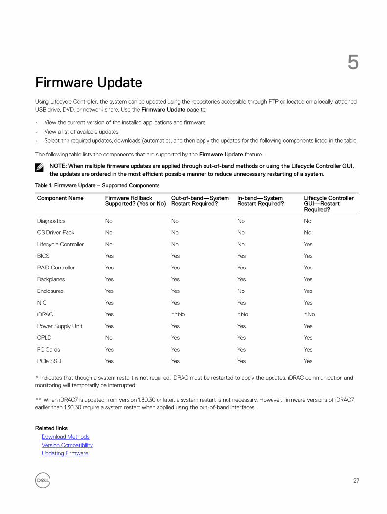
5Firmware UpdateUsing Lifecycle Controller, the system can be updated using the repositories accessible through FTP or located on a locally-attached USB drive, DVD, or network share. Use the Firmware Update page to:
• View the current version of the installed applications and firmware.
• View a list of available updates.
• Select the required updates, downloads (automatic), and then apply the updates for the following components listed in the table.
The following table lists the components that are supported by the Firmware Update feature.
NOTE: When multiple firmware updates are applied through out-of-band methods or using the Lifecycle Controller GUI, the updates are ordered in the most efficient possible manner to reduce unnecessary restarting of a system.
Table 1. Firmware Update – Supported Components
Component Name Firmware Rollback Supported? (Yes or No)
Out-of-band—System Restart Required?
In-band—System Restart Required?
Lifecycle Controller GUI—Restart Required?
Diagnostics No No No No
OS Driver Pack No No No No
Lifecycle Controller No No No Yes
BIOS Yes Yes Yes Yes
RAID Controller Yes Yes Yes Yes
Backplanes Yes Yes Yes Yes
Enclosures Yes Yes No Yes
NIC Yes Yes Yes Yes
iDRAC Yes **No *No *No
Power Supply Unit Yes Yes Yes Yes
CPLD No Yes Yes Yes
FC Cards Yes Yes Yes Yes
PCIe SSD Yes Yes Yes Yes
* Indicates that though a system restart is not required, iDRAC must be restarted to apply the updates. iDRAC communication and monitoring will temporarily be interrupted.
** When iDRAC7 is updated from version 1.30.30 or later, a system restart is not necessary. However, firmware versions of iDRAC7 earlier than 1.30.30 require a system restart when applied using the out-of-band interfaces.
Related links
Download Methods
Version Compatibility
Updating Firmware
27

Download MethodsThe following table lists the various locations or media and methods to perform the updates:
NOTE: If the FTP server or network share is used for updates, configure the network card using Settings wizard before accessing the updates.
Table 2. Firmware Update Methods
Location FTP
Methods • Non-proxy (Internal, or Service Provider)
• Proxy (Internal, or Service Provider)
Media Local Drive
• SUU DVD
• USB Drive
• Dell Lifecycle Controller OS Driver Packs DVD
Methods • Virtual Console (Mapped on Client)
• Attached Locally
Location Network Share
• CIFS
• NFS
Version CompatibilityThe version compatibility feature enables you to update the component firmware versions that are compatible with system components. In case of compatibility issues, Lifecycle Controller displays upgrade or downgrade error messages during update.
Updating FirmwareYou can update to the latest version of Lifecycle Controller using the Firmware Update wizard. It is recommended that you run the Firmware Update wizard on a regular-basis to access the latest updates. You can update the component firmware either by using update repositories or individual DUPs (single component DUP.)
NOTE: Make sure that the file name for the single component DUPs does not have any blank space.
NOTE: If Collect System Inventory On Restart (CSIOR) is disabled while performing an update, Lifecycle Controller automatically updates the system inventory.
NOTE: Both 32–bit and 64–bit DUPs and catalog are supported.
NOTE: During BIOS update, due to security reasons, the progress bar stops at 40 seconds, jumps to 1 minute 50 seconds after a while, and then completes.
To update the firmware:
1. In the left pane, click Firmware Update.
2. In the right pane, click Launch Firmware Update.
3. To indicate the repository where the firmware file is stored, select any one of these update repositories: FTP Server, Local Drive, or Network Share, click Next.
The Enter Access Details page is displayed.
4. Type or select appropriate data.
28

5. To verify if Lifecycle Controller is able to connect to the IP address that is provided, click Test Network Connection. By default, it PINGs the Gateway IP, DNS server IP, host IP, and proxy IP (if provided).
NOTE: Lifecycle Controller cannot PING to the domain name and does not display its IP address, if the DNS is not able to resolve the domain name. Make sure that the issue with DNS is resolved and retry.
6. Click Next.
The Select Updates page is displayed with the catalog file, catalog version, and component names for which the updates are available.
7. Select the components that require an update, and then click Apply.
The update process is initiated and the firmware update is completed. After restart, the system is ready to use.
NOTE: The system does not restart if operating system driver packs or hardware diagnostics are updated.
NOTE: When applying more than one update, the system may need to restart between updates. In this case, Lifecycle Controller restarts the server and automatically continues the update process.
NOTE: iDRAC will reset while updating iDRAC, CPLD, or Power Supply.
NOTE: After the CPLD firmware is updated on the modular servers, on the View Current Versions page, under Firmware Update, the firmware update date is displayed as 2000-01-01, regardless of the actual update date. The updated date and time is displayed on the basis of time zone that is configured on the server.
NOTE: If the iDRAC firmware update is interrupted for any reason, wait for up to 30 minutes before you attempt another firmware update.
Related links
Firmware Update
Download Methods
Version Compatibility
Selecting Type of Update And Update Source
Selecting and Applying Updates
Updating or Rolling Back Devices That Affect Trusted Platform Module Settings
Selecting Type of Update And Update Source
To perform the updates, you can download single component DUPs or repository (Catalog.xml) using the Firmware Update wizard to one of the following:
NOTE: The Catalog.xml file contains the individual server bundles. Each bundle consists of all the DUP information (md5 security key, date and time, path, Release ID, version, and so on.)
• FTP server — Dell FTP Server, Local FTP, or FTP server using a proxy server.
NOTE: Make sure that the repository (catalog file) and DUPs that are downloaded from ftp.dell.com are copied into the root folder of the source.
• Local Drive — Use a USB drive, Dell Server Updates DVD, or Lifecycle Controller OS Driver Packs DVD.
• Network Share
Related links
Comparing Firmware Versions
Using Single Component DUPs
Using Local Drive
Using FTP Server
Using Network Share
Updating or Rolling Back Devices That Affect Trusted Platform Module Settings
Using Local Drive
Lifecycle Controller allows you to perform platform updates using locally available DVDs or USB drives, or by using Virtual Media. This flexibility improves the efficiency of the update process when there is a high network traffic. After selecting the update repository,
29

Lifecycle Controller automatically detects any necessary updates, and then performs those updates either on components you specifically select.
To access the repository on the local drive, create a repository on a DVD or USB drive.
Using a DVDUse either Server Update Utility (SUU) DVDs or custom DVDs (SUU ISO downloaded from support.dell.com and written to a DVD) to perform firmware updates. The available DVDs are:
• OpenManage SUU DVD to update all the server components such as Lifecycle Controller, Dell Diagnostics, BIOS, RAID Controller, NIC, iDRAC, and Power Supply Unit.
• Lifecycle Controller OS Driver Packs DVD (Windows only) to update the operating system driver packs.
To access the updates from a DVD:
1. Insert the appropriate DVD in the locally-attached CD/DVD drive. Alternatively, insert the appropriate DVD in the client and use the Virtual Media feature to access the attached CD/DVD drive. For more information, see the iDRAC7 User’s Guide.
2. From the Local Drive drop-down menu, select the drive that contains the updated DVD.
3. In the File Path or Update package path box, enter the location or sub-directory where the catalog is stored.
NOTE: If the catalog file is located in the root folder, do not enter the file name in the File Path or Update package path box. However, if the catalog file is located in a sub-directory, enter the sub-directory name (for example, subdirectory).
NOTE: If the catalog file or DUP is downloaded from ftp.dell.com, do not copy them into a sub-directory.
NOTE: Lifecycle Controller allows 256 characters in a path, and does not support special characters such as :, *, ?, ", <, >, |, #, %, and ^ in folder names.
Using a USB DriveYou can download the repository from the SUU DVD or an FTP to a USB drive, and then access the updates from this drive.Before you perform any updates, make sure the following prerequisites are met:
• The updates are downloaded using the Dell Repository Manager and the repository is created on a USB drive.
NOTE: To download the complete repository, make sure that the USB drive has 8 GB free disk space.
• Connect USB drive to the system.
To update the platform using USB drive:
1. Insert a USB drive to the managed system. Alternatively, insert the USB drive to the client system and use the Virtual Media feature to access the USB drive. For more information about this feature, see the iDRAC7 User’s Guide available at dell.com/support/manuals.
2. From the Select Device drop-down menu, select the USB drive that contains the updates (DUP or repository).
3. In the File Path or Update package path box, type the location or sub-directory where the catalog file is stored.
NOTE: If the catalog file is located in a root folder, do not enter the file name in the File Path or Update package path box. However, if the catalog file is located in a sub-directory, enter the sub-directory name (for example, subdirectory).
NOTE: If the catalog file or DUP is downloaded from ftp.dell.com, do not copy them into a subdirectory.
NOTE: Lifecycle Controller allows 256 characters in a path and does not support special characters such as :, *, ?, ", <, >, |, #, %, and ^ in folder names.
Using FTP Server
Lifecycle Controller provides options to update a server using the latest firmware available on the Dell FTP server or internal FTP server. To use the Dell FTP, local FTP, or service provider's FTP server that is configured as proxy or non-proxy, use the following options:
• Using Non-Proxy FTP Server
30
• Using Proxy FTP Server
Related links
Accessing Updates on a Local FTP Server
Configuring Local USB Drive
Using Non-Proxy FTP ServerLifecycle Controller can access the latest firmware from ftp.dell.com. It downloads the DUPs from this location to perform firmware update.
Before performing an update, make sure the following prerequisites are met:
• The network settings are configured (Settings → Network Settings).
• The updates are downloaded using Dell Repository Manager, and the repository is created on an internal FTP server.
To update the system using Dell FTP server, internal FTP server, or service provider’s FTP server:
• Dell FTP Server — In the Address box, enter only ftp.dell.com.
• Internal FTP server or service provider’s FTP server — Enter the following details:
– User Name — The user name to access the FTP location.
– Password — The password to access the FTP location.
– File Path or Update package path — Name of the DUP location or sub-directory where the catalog is stored.
This step is optional for operating system driver source.
NOTE: If the catalog file is located in the root folder, do not enter the file name in the File Path or Update package path box. However, if the catalog file is located in a sub-directory, enter the sub-directory name (for example, subdirectory).
NOTE: If the catalog file or DUP is downloaded from ftp.dell.com, do not copy them into a sub-directory.
NOTE: Lifecycle Controller allows 256 characters in a path, and does not support special characters such as :, *, ?, ", <, >, |, #, %, and ^ in folder names.
For more information, contact your system administrator or service provider for the information.
Using Proxy FTP ServerUsing Lifecycle Controller, you can update the firmware by using ftp.dell.com, or by using an internal FTP server or service provider’s FTP server, when you are connected to the Internet through a proxy server.
Before updating, make sure the following prerequisites are met:
• The network settings are configured (Settings → Network Settings).
• The updates are downloaded using the Dell Repository Manager, and the repository is created on an internal FTP server.
• The proxy server supports either HTTP or SOCKS4 protocols.
• Information related to proxy server such as IP address or host name of the proxy server, login credentials, and the port number are readily available.
To update the system using Dell FTP server or an internal FTP server, or service provider’s FTP server in proxy-connection environment:
• Dell FTP Server — In the Address box, enter ftp.dell.com, and under the Proxy Settings section, enter the proxy server information.
• Internal FTP server or service provider’s FTP server — Enter the following details:
– User Name — The user name to access the FTP location.
– Password — The password to access the FTP location.
– File Path or Update package path — Name of the DUP location or sub-directory where the catalog is stored.
NOTE: If the catalog file is located in the root folder, do not enter the file name in the File Path or Update package path box. However, if the catalog file is located in a sub-directory, enter the sub-directory name (for example, subdirectory).
31

NOTE: If the catalog file or DUP is downloaded from ftp.dell.com, do not copy them into a sub-directory.
NOTE: Lifecycle Controller allows 256 characters in a path, and does not support special characters such as :, *, ?, ", <, >, |, #, %, and ^ in folder names.
• Enable Settings — Select this option to enter the following details:
• Server — The server host name of the proxy server.
• Port — The port number of the proxy server.
• User Name — The user name required for authentication on the proxy server.
• Password — The password required for authentication on the proxy server.
• Type — The type of proxy server. HTTP and SOCKS 4 proxy types are supported by Lifecycle Controller.
For more information, contact your system administrator or service provider.
Using Network Share
To use a shared folder over a network, select Network Share (CIFS or NFS) and enter the details provided in the following table:Table 3. Network Share Details
For CIFS For NFS
Share Name — Path to the shared folder where the DUPs or repository is located. For example, \\192.168.20.26\sharename or \\servername\sharename.
Domain and User Name — Type the correct domain and user name required to log on to the network share. For example, login-name@myDomain, and if there is no domain, type only the login name. For example, login-name.
NA
Password — Password to authenticate the user name. NA
File PathorUpdate package path — Name of the DUP location or sub-directory, where the catalog is stored.
NOTE: If the catalog file is located in the root folder, do not enter the file name in the File Path or Update package path box. However, if the catalog file is located in a sub-directory, enter the sub-directory name (for example, subdirectory).
NOTE: If the catalog file and DUP are downloaded from ftp.dell.com, do not copy them into a sub-directory.
NOTE: Lifecycle Controller allows 256 characters in a path, and does not support special characters such as :, *, ?, ", <, >, |, #, %, and ^ in folder names.
Using Single Component DUPs
To use single component (Dell Update Packages) DUP, download the Dell Update Package (only .exe) from the Dell FTP site (ftp.dell.com), and then copy from the Server Update Utility DVD, or from support.dell.com to a local HDD or network share.
NOTE: Make sure that the file name for the single component DUPs does not have any blank space.
NOTE: Both 32–bit and 64–bit DUPs are supported.
In the File Path or Update package path box, enter the name of the DUP (for example, APP_WIN_RYYYZZZ.EXE) or if the DUP is present in a sub-directory, enter both the sub-directory name and name of the DUP (for example, subdirectory\APP_WIN_RYYYZZZ.EXE).
NOTE: Lifecycle Controller allows 256 characters in a path, and does not support special characters such as :, *, ?, ", <, >, |, #, %, and ^ in folder names.
Selecting and Applying Updates
1. To select and apply the updates, from the Available System Updates table, click the option corresponding to the component that has the firmware you want to update to. After you select, the catalog ID details of the firmware selected is displayed in the following format.
Release Date: YYYY-MM-DD
Source: USB Driveor CD or DVD (<device type>): \<firmware file name in .exe format>.
32

By default, Lifecycle Controller selects the components for which the current updates are available. For more information, see the Lifecycle Controller online help.
2. Click Apply. The system restarts after the update process is complete. When applying more than one update, the system restarts between updates directly into Lifecycle Controller, and continues with the other selected updates.
NOTE: The system does not restart after updating the OS driver pack and hardware diagnostics.
NOTE: While using Lifecycle Controller to update the power supply unit (PSU) firmware, the system turns off after the first task. It takes a couple of minutes to update the PSU firmware, and then automatically turns on the server.
Firmware RollbackLifecycle Controller allows you to roll back to a previously-installed version of component firmware such as BIOS, iDRAC, RAID Controller, NIC, Enclosure, Backplane, Fibre Channel cards, and Power Supply Unit. It is recommended to use this feature if you have a problem with the current version, and want to revert to the previously‑installed version.
• The Dell Diagnostics, OS driver packs, CPLD, and Lifecycle Controller firmware cannot be rolled back to earlier versions.
• The earlier version is available only if the component firmware is updated at least once to a different version.
• Every time an image is updated, the earlier version of the firmware image is backed up.
• Every time a rollback operation is performed, the previously-installed firmware becomes the current version, and the previous version will not be available. However, for iDRAC, previously installed version becomes the current version and the current version is stored as the previous version.
• The earlier version of the firmware is available only if any of the following tools are used to update the firmware: Lifecycle Controller Firmware Update feature, Lifecycle Controller-Remote Services, or the Dell Update Package. However, the previous version of PSU firmware is available if Lifecycle Controller Firmware Update feature or Lifecycle Controller-Remote Services is used to update the firmware.
Related links
Rolling Back to Previous Firmware Versions
Rolling Back to Previous Firmware Versions
You can roll back to earlier versions of a firmware using the Firmware Rollback wizard.
NOTE: If you update any firmware only once, the rollback feature provides the option to revert to the factory-installed component firmware image. If you update the firmware more than once, the factory‑installed images are overwritten and you cannot revert to them.
To roll back a firmware:
1. In the left pane, click Firmware Update.
2. In the right pane, click Launch Firmware Rollback.
The Firmware Rollback page displays a list of components for which rollback is available and the later versions are selected by default.
3. Select the required rollback image and click Apply.
After the update process is complete, the system restarts. When applying more than one update, the system may restart between updates directly into Lifecycle Controller and continue updating.
Related links
Firmware Rollback
Comparing Firmware Versions
Updating or Rolling Back Devices That Affect Trusted Platform Module Settings
33

Comparing Firmware Versions
To compare the version of the update or rollback with the version currently installed on the system, compare the versions in the Current and Available fields:
• Component — Displays the name of the components. Select the option corresponding to the component that you want to update.
• Current — Displays the component version currently installed on the system.
• Available — Displays the version of the available firmware.
Updating or Rolling Back Devices That Affect Trusted Platform Module Settings
Enabling Trusted Platform Module (TPM) with pre-boot measurement enables the BitLocker protection on the system. When BitLocker protection is enabled, updating or rolling back the components such as RAID controller, NIC, and BIOS require that a recovery password is entered or a USB drive that contains a recovery key is inserted during the next system restart. For information on how to set TPM settings, see the BIOS User Guide available at dell.com/support/manuals.
When Lifecycle Controller detects that TPM security is set to On with Pre-boot Measurements, a message indicates that certain updates require the recovery password or USB drive with the recovery key. The message also indicates components that affect the BitLocker.
You can choose not to update or roll back those components by navigating to the Select Updates page, and then clearing the options for the appropriate components.
34

6ConfigureLifecycle Controller provides various system configuration wizards. Use the configuration wizards to configure system devices. The Configuration Wizards has:
• System Configuration Wizards — This includes LCD Panel Security, iDRAC Settings, System Date and Time Configuration, and vFlash SD card Configuration.
• Storage Configuration Wizards — This includes RAID Configuration, Key Encryption, and Break Mirror.
Related links
Controlling Access to Front Panel
Configuring iDRAC
Configuring System Time And Date
Configuring vFlash SD Card
Configuring RAID
Configuring RAID Using Software RAID
Creating a Secure Virtual Disk on Series 8 Controller
Applying the Local Key On RAID Controller
Breaking Mirrored Drives
System Control Panel Access OptionsLifecycle Controller front panel security configuration enables an administrator to restrict access to system control panel interface. The options available are:
• View and Modify — You can obtain information and make changes using the system control panel interface.
• View Only — You can move through the data screens to obtain information using the system control panel interface.
• Disable — You do not have access to information or control, other than the information displayed by the management controller, and you cannot specify actions.
Controlling Access to Front Panel
To control access to the front panel:
1. From the Lifecycle Controller Home page, select Hardware Configuration.
2. In the right pane, select Configuration Wizards.
3. On the System Configuration Wizards page, click LCD Panel Security.
4. Set System Control Panel Access to one of the following options:
• View and Modify
• View Only
• Disable
5. Click Finish to apply the changes.
Configuring iDRACTo configure iDRAC parameters applicable to the system, such as LAN, common IP settings, IPv4, IPv6, Virtual Media, and LAN user configuration use the iDRAC Settings wizard.
35
NOTE: You can also use the System Setup utility during startup for configuring iDRAC. For more information about the System Setup utility, see the Using The System Setup Program And Boot Manager chapter in this User's Guide.
To configure and manage the iDRAC parameters:
1. In the left pane of Home page, click Hardware Configuration.
2. In the right pane, click Configuration Wizards.
3. Under System Configuration Wizards, click iDRAC Settings, and then click the following options to configure different iDRAC parameters.
For more information about configuring iDRAC settings, see the iDRAC7 User's Guide.
NOTE: Click System Summary to view the parameters and their values.
• Network
• OS to iDRAC Pass Through
• Alerts
• System Event Log
• Virtual Media
• vFlash Media
• Thermal
• System Location
• Front Panel Security
• User Configuration
• Smart Card
• Lifecycle Controller
• Remote Enablement
• Reset iDRAC Configuration to defaults
4. Click Back after setting the parameters for each option.
5. Click Finish to apply the changes.
Configuring System Time And DateTo set the time and date for the managed system:
1. From the Lifecycle Controller Home page, select Hardware Configuration.
2. In the right pane, select Configuration Wizards.
3. Under System Configuration Wizards, click System Time and Date Configuration.
The default system time and system date shown in Lifecycle Controller is the date and time reported by the system BIOS.
4. Modify the System Time and System Date (HH:MM:SS AM or PM), as required.
5. Click Finish to apply the changes.
Configuring vFlash SD CardUse the licensed feature to enable or disable the vFlash SD card, check the health and properties, and initialize the vFlash SD card. Lifecycle Controller support vFlash SD cards of sizes 1 GB, 2 GB, 8 GB, 16 GB, and 32 GB.
NOTE: The options under vFlash SD card are grayed-out if there is no SD card inserted in the slot.
See the Integrated Dell Remote Access Controller 7 (iDRAC7) User’s Guide available at dell.com/support/manuals for more information on vFlash SD card and the installation procedure.
36
Use the vFlash SD card configuration feature to:
• Enable or disable vFlash SD card.
• Determine the vFlash SD card properties:
– Name
– Health — Displays health states such as OK, Warning, and Critical .
– Size — Indicates the total size of the vFlash SD card.
– Available Space — Indicates the available size on the vFlash SD card to create a new partition.
– Write Protected — Indicates if the write-protect latch on the vFlash SD card is set to on or off position.
• Initialize vFlash — This deletes all the existing partitions on vFlash SD card.
Enabling or Disabling vFlash
Make sure to set the write-protect latch on the vFlash SD card to Off position.If set to Enabled, the vFlash SD card is configured as a virtual drive that appears in the BIOS boot order, allowing you to boot from the vFlash SD card. If set to Disabled, virtual flash is not accessible.
To enable or disable vFlash SD card:
1. In the left pane, click Hardware Configuration.
2. In the right pane, click Configuration Wizards.
3. Under System Configuration Wizards, click vFlash SD Card Configuration.
The vFlash SD Card page is displayed.
4. From the vFlash Media drop-down menu, select Enabled or Disabled.
5. Click Finish to apply the changes.
Initializing vFlash
1. On the System Configuration Wizardspage, click vFlash SD Card Configuration.
The vFlash SD Card page is displayed.
2. Click Initialize vFlash to delete all the data present in the vFlash SD card.
NOTE: The Initialize vFlash option is not available after you disable the vFlash SD card.
Configuring RAIDIf your system has one or more supported PERC RAID controllers with PERC 8 firmware or later, or SAS RAID controllers, use the RAID Configuration wizard to configure a virtual disk as the boot device.
NOTE: If there are any internal storage controller cards on the system, all other external cards cannot be configured. If there are no internal cards, then external cards can be configured.
To configure RAID:
1. In the left pane, click Hardware Configuration.
2. In the right pane, click Configuration Wizards.
3. Under Storage Configuration Wizards, click RAID Configuration to launch the wizard.
The View Current RAID Configuration and Select Controller page is displayed.
4. Select the controller and click Next.
The Select RAID Level page is displayed.
5. Select the RAID level and click Next.
The Select Physical Disks page is displayed.
6. Select the physical disk's properties and click Next.
The Virtual Disk Attributes page is displayed.
37

7. Select the virtual disk parameters and click Next.
The Summary page is displayed.
8. To apply the RAID configuration, click Finish.
Related links
Viewing Current RAID Configuration
Selecting RAID Controller
Foreign Configuration Found
Selecting RAID Levels
Selecting Physical Disks
Setting Virtual Disk Attributes
Viewing Summary
Foreign Configuration Found
The Foreign Configuration Found page is displayed only if a foreign configuration hard disk drive resides on the selected RAID controller.
NOTE: If you have selected an S110 RAID controller, the foreign disk drives are displayed as non-RAID hard disk drives in Lifecycle Controller. You must initialize them to create a virtual disk.
A foreign configuration is a set of physical disk drives containing a RAID configuration that has been introduced to the system, but is not managed by the RAID controller to which it is attached. You may have a foreign configuration if physical disk drives have been moved from a RAID controller on another system to a RAID controller on the current system.
You have two options: Ignore Foreign Configuration and Clear Foreign Configuration.
• If the foreign configuration contains data that you require, click Ignore Foreign Configuration. If you click this option, the disk drive space containing the foreign configuration is not available for use in a new virtual drive.
• To delete all data on the physical disk drives containing the foreign configuration, click Clear Foreign Configuration. This option deletes the hard disk drive space containing the foreign configuration and makes it available for use in a new virtual drive.
After selecting one of the options, click Next.
Viewing Current RAID Configuration
The View Current RAID Configuration and Select Controller page displays the attributes of any virtual disks already configured on the supported RAID controllers attached to the system. You have two options:
• Accept the existing virtual disks without changing. To select this option, click Back. If you have to install the operating system on an existing virtual disk, make sure that the virtual disk size and RAID level are correct.
• Use the RAID configuration wizard to delete all the existing virtual disks and create only single and new virtual disk to be used as the new boot device. To select this option, click Next.
NOTE: RAID 0 does not provide data redundancy and hot spare. Other RAID levels provide data redundancy and enable you to reconstruct data in the event of a disk drive failure.
NOTE: You can create only one virtual disk using Lifecycle Controller. To create multiple virtual disks, use option ROM. To access option ROM, press <Ctrl + R> during boot or Power-on Self-test (POST).
Selecting RAID Controller
The View Current RAID Configuration and Select Controller page displays all supported RAID controllers attached to the system. Select the RAID controller on which you want to create the virtual disk, and then click Next.
Selecting RAID Levels
Select a RAID Level for the virtual disk:
38

• RAID 0 — Stripes data across the physical disks. RAID 0 does not maintain redundant data. When a physical disk fails in a RAID 0 virtual disk, there is no method for rebuilding the data. RAID 0 offers good read and write performance with zero data redundancy.
• RAID 1 — Mirrors or duplicates data from one physical disk to another. If a physical disk fails, data can be rebuilt using the data from the other side of the mirror. RAID 1 offers good read performance and average write performance with good data redundancy.
• RAID 5 — Stripes data across the physical disks, and uses parity information to maintain redundant data. If a physical disk fails, the data can be rebuilt using the parity information. RAID 5 offers good read performance and slower write performance with good data redundancy.
• RAID 6 — Stripes data across the physical disks, and uses two sets of parity information for additional data redundancy. If one or two physical disks fail, the data can be rebuilt using the parity information. RAID 6 offers good data redundancy and read performance but slower write performance.
• RAID 10 — Combines mirrored physical disks with data striping. If a physical disk fails, data can be rebuilt using the mirrored data. RAID 10 offers good read and write performance with good data redundancy.
• RAID 50 — A dual-level array that uses multiple RAID 5 sets in a single array. A single physical disk failure can occur in each of the RAID 5 without any loss of data on the entire array. Although the RAID 50 has increased write performance, its performance decreases, data or program access gets slower, and transfer speeds on the array are affected when a physical disk fails and reconstruction takes place.
• RAID 60 — Combines the straight block level striping of RAID 0 with the distributed double parity of RAID 6. The system must have at least eight physical disks to use RAID 60. Failures while a single physical disk is rebuilding in one RAID 6 set do not lead to data loss. RAID 60 has improved fault tolerance because more than two physical disks on either span must fail for data loss to occur.
Minimum Disk Requirement for Different RAID Levels
Table 4. : RAID Level and Number of Disks
RAID Level Minimum Number of Disks
0 1*
1 2
5 3
6 4
10 4
50 6
60 8
* For S110 RAID controller, a minimum of two hard disk drives are required.
Selecting Physical Disks
Use the Select Physical Disks screen to select the physical disks to be used for the virtual drive and select the physical disk drive-related properties.
The number of physical disks required for the virtual disk varies depending on the RAID level. The minimum and maximum numbers of physical disks required for the RAID level are displayed on the screen.
• Protocol — Select the protocol for the disk pool: Serial Attached SCSI (SAS) or Serial ATA (SATA). SAS drives are used for high performance, while SATA drives provide a more cost-effective solution. A disk pool is a logical grouping of physical disk drives on which one or more virtual drives can be created. The protocol is the type of technology used to implement RAID.
• Media Type — Select the media type for the disk pool: Hard Disk Drives (HDD) or Solid State Disks (SSD). HDDs use traditional rotational magnetic media for data storage and SSDs implement flash memory for data storage.
• Encryption Capability — Select Yes to enable encryption capability
39
• Select Span Length — Select the span length. The span length value refers to the number of physical disk drives included in each span. Span length applies only to RAID 10, RAID 50, and RAID 60. The Select Span Length drop‑down list is active only if the user has selected RAID-10, RAID-50, or RAID 60.
• Drives remaining for current span — Displays the number of physical disk drives available based on the span length value.
• Select the physical disk drives using the check boxes at the bottom of the screen. The physical disk drive selection must meet the requirements of the RAID level and span length. To select all the physical disk drives, click Select All. After you select the option, the option changes to Deselect.
Setting Virtual Disk Attributes
Use this page to specify the values for the following virtual drive attributes:
• Size — Specify the size of the virtual drive.
• Stripe Element Size — Select the stripe element size. The stripe element size is the amount of drive space a stripe consumes on each physical disk drive in the stripe. The Stripe Element Size list may contain more options than initially displayed on the screen. Use the UP ARROW and DOWN ARROW keys to view all available options.
• Read Policy — Select the read policy:
– Read Ahead — The controller reads sequential sectors of the virtual drives when seeking data. The Read Ahead policy may improve system performance if the data is written to sequential sectors of the virtual drives.
– No Read Ahead — The controller does not use the Read Ahead policy. The No Read Ahead policy may improve system performance, if the data is random and not written to sequential sectors.
– Adaptive Read Ahead — The controller initiates the Read Ahead policy only if the most-recently-read requests accessed sequential sectors of the disk drive. If the most-recently-read requests accesses random sectors of the disk drive, then the controller uses the No Read Ahead policy.
• Write Policy — Select the write policy.
– Write Through — The controller sends a write-request-completion signal only after the data is written to the disk drive. The Write Through policy provides better data security than the Write Back policy, because the system assumes the data is available only after it has been written to the disk drive.
– Write Back — The controller sends a write-request completion signal as soon as the data is in the controller cache, but has not yet been written to disk drive. The Write Back policy may provide faster 'write' performance, but it also provides less data security, because a system failure can prevent the data from being written to disk drive.
– Force Write Back — The write cache is enabled regardless of whether or not the controller has an operational battery. If the controller does not have an operational battery, data loss may occur in the event of a power failure.
• Assign a Hot Spare Disk if available — Select this option to assign a hot spare to the virtual drive.
A hot spare is an unused backup physical disk drive that is used to rebuild data from a redundant virtual drive. A hot spare can be used only with a redundant RAID level. Hot spares also have requirements for physical disk drive size. The hot spare must be as big as or bigger than the smallest physical disk drive included in the virtual drive. If the RAID level and physical disk drive availability do not meet these requirements, a hot spare is not assigned.
• Hot Spare Disk — Select a disk that will be used as a hot spare. Only one dedicated hot spare is supported in Lifecycle Controller.
• Secure Virtual Disk — Select the option to secure the virtual drive using the controller’s security key.
NOTE: The secure virtual drive is created only if the controller security key is created and the selected disks are Self-Encrypting Drives (SEDs).
Viewing Summary
The Summary page displays the virtual disk attributes on the basis of selections.
CAUTION: Clicking Finish deletes all existing virtual drives except any foreign configurations that you specified. All data residing on the virtual drives is lost.
To return to a previous page to review or change selections, click Back. To close the Wizard without making changes, click Cancel.
Click Finish to create a virtual drive with the displayed attributes.
40

Configuring RAID Using Software RAIDFor the S110 controller, make sure to change the SATA Controller option to RAID Mode. To do this through BIOS, the latest BIOS version must be installed. For more information about the BIOS versions for different systems, see Lifecycle Controller Release Notes.
NOTE: For more information about RAID configuration, see the How to create RAID using Lifecycle Controller white paper available at delltechcenter.com/lc.
NOTE: If you have an older BIOS, you can configure RAID only through Option ROM.
Use this feature to configure RAID if a PERC S110 controller is enabled on the system. If the software RAID option is selected, Lifecycle Controller displays the physical disk drives as Non-RAID disks or RAID-ready disks.
• Non-RAID disk — A single disk drive without any RAID properties. Needs initialization to apply RAID levels.
• RAID-ready disk — The disk drive is initialized and a RAID level can be applied.
NOTE: Linux and VMware operating systems cannot be installed by using Software RAID controller (S110).
To configure software RAID:
1. In the left pane, click Hardware Configuration.
2. In the right pane, click Configuration Wizards.
3. Under Storage Configuration Wizards, click RAID Configuration to launch the wizard:
The View Current RAID Configuration and Select Controller page is displayed.
4. Select the controller and click Next.
If the non-RAID disk drives are attached to the selected controller, select the non-RAID physical disk drives, and then click Next to initialize them. Else, the Select RAID Level page is displayed.
NOTE: During initialization, all the data on the non-RAID disk drives are deleted.
5. Select the RAID level and click Next.
The Select Physical Disks page is displayed.
6. Select the physical disk properties and click Next.
The Virtual Disk Attributes page is displayed.
7. Select the virtual disk parameters and click Next.
The Summary page is displayed.
8. To apply the RAID configuration, click Finish.
Related links
Selecting RAID Controller
Foreign Configuration Found
Selecting RAID Levels
Selecting Physical Disks
Setting Virtual Disk Attributes
Viewing Summary
Creating a Secure Virtual Disk on Series 8 ControllerMake sure that the controller is encrypted with a Local Key.To create a secure virtual disk on series 8 controller:
1. In the left pane, click Hardware Configuration.
2. In the right pane, click Configuration Wizards.
3. Under Storage Configuration Wizards, click RAID Configuration to launch the wizard.
41

The View Current RAID Configuration and Select Controller page is displayed along with the information on whether or not the displayed virtual disk is secure.
4. Select the controller and click Next.
If the non-RAID disks are attached to the selected controller, select the non-RAID physical disk drives, and then click Next to initialize them. Else, the Select RAID Level page is displayed.
NOTE: During initialization, all the data on the non-RAID disk drives are deleted.
5. Select the RAID level and click Next.
The Select Physical Disks page is displayed.
6. From the Encryption Capability drop-down menu, select Self-encryption.
The self-encryption disks (SEDs) are displayed.
7. Select the SEDs and specify the properties, and then click Next.
The Virtual Disk Attributes page is displayed.
8. Select the virtual disk parameters, select the Secure Virtual Disk option, and click Next.
The Summary page is displayed.
9. To apply the RAID configuration, click Finish.
Related linksSelecting RAID ControllerForeign Configuration FoundSelecting RAID LevelsSelecting Physical DisksSetting Virtual Disk AttributesViewing SummaryApplying the Local Key On RAID Controller
Key EncryptionUse this feature to:
• Apply local encryption for PERC H710, H710P, and H810 RAID controllers.
• Delete the local encryption key.
• Encrypt the existing unsecure virtual drives.
• To change an existing encryption key to another one.
NOTE: The H730P controller is supported on the Equinox(R920) Server.
NOTE: For more information about the Key encryption feature, see the Key Encryption in Lifecycle Controller white paper available at delltechcenter.com/lc.
Applying the Local Key On RAID Controller
Before applying the local key on a RAID controller, make sure that the controller is security-capable.
To apply the local key on a RAID controller:
1. In the left pane, click Hardware Configuration.
2. In the right pane, click Configuration Wizards.
3. Under Storage Configuration wizards, click Key Encryption.
4. Select the controller to apply a local key and click Next.
5. Click Set up local key encryption and click Next.
NOTE: Some controller options are disabled if they do not support encryption.
6. Enter the Encryption Key Identifier that is associated with the entered passphrase. The Encryption Key Identifier is a passphrase hint; you must enter the passphrase when Lifecycle Controller prompts with this hint.
42

7. In the New Passphrase text box, enter a passphrase.
NOTE: The controller uses the passphrase to encrypt the disk drive data. A valid passphrase contains 8 to 32 characters. It must include a combination of uppercase and lowercase letters, numbers, symbols, and without spaces.
8. In the Confirm Passphrase text box, re-enter the passphrase, and then click Finish.
Local Key Encryption ModeYou can perform the following tasks while the controller is in the Local Key Encryption mode:
NOTE: For more information on the specification and configuration-related information for the PERC H710, H710P, H810, and PERC 9 controllers, see the PERC H710, H710P, and H810 Technical Guidebooks.
• Encrypt unsecure virtual disks — Enable data encryption on all the security-capable, unsecure virtual drives.
NOTE: This option is available if there are secure-capable virtual disks connected to a security-capable controller.
• Rekey controller and encrypted disks with a new key — Replace the existing local key with a new key.
• Remove encryption and delete data — Delete the encryption key on the controller and all the secure virtual drives along with its data. After deletion, controller state changes to No encryption mode.
Related links
Encrypting Unsecure Virtual Disks
Rekey Controller With New Local Key
Removing Encryption and Deleting Data
Encrypting Unsecure Virtual Disks
Make sure that the following prerequisites are met:
• Selected controller is security-capable.
• Security-capable virtual drives must be attached to the controller.
• Controller must be in the local-key-encryption mode.
To encrypt the unsecure virtual drives:
NOTE: All virtual drives created under the same physical disk drives are automatically encrypted.
1. In the left pane, click Hardware Configuration.
2. In the right pane, click Configuration Wizards.
3. On the Storage Configuration wizards page, click Key Encryption.
4. Select the controller that is encrypted and click Next.
NOTE: The encryption mode (Local Key Encryption) applied to the selected controller does not change.
5. Select Encrypt unsecure virtual disks and click Next.
6. To enable encryption, select the unsecure virtual drives and click Finish.
Related links
Local Key Encryption Mode
Rekey Controller With New Local Key
To rekey the controller with a new local key:
1. In the left pane, click Hardware Configuration.
2. In the right pane, click Configuration Wizards.
3. On the Storage Configuration wizards, click Key Encryption.
43
4. Select the controller to which the local key is applied and click Next.
5. In the Existing Passphrase box, enter the existing passphrase associated with the displayed Encryption Key Identifier.
6. In the New Encryption Key Identifier box, enter the new identifier. The Encryption Key Identifier is a passphrase hint; you must enter the passphrase when Lifecycle Controller prompts for this hint.
7. In the New Passphrase box, enter the passphrase that will be associated with the new encryption key identifier
Related links
Local Key Encryption Mode
Removing Encryption and Deleting Data
To remove the encryption and delete the data on the virtual disks:
1. In the left pane, click Hardware Configuration.
2. In the right pane, click Configuration Wizards and click Key Encryption.
3. Select the controller on which you must remove the key that was applied and click Next.
4. In the right pane, select Remove encryption and delete data and click Next.
5. Select Delete encryption key and all secure virtual disks and click Finish.
CAUTION: The existing encryption, virtual drives, and all the data are permanently deleted.
Related links
Local Key Encryption Mode
Breaking Mirrored DrivesTo split the mirrored array of RAID-1 virtual drives:
1. In the left pane, click Hardware Configuration.
2. In the right pane, click Configuration Wizards.
3. Under Storage Configuration wizards, click Break Mirror.
The Break Mirror page is displayed with the mirrored virtual drives.
4. Select the related controller and click Finish.
NOTE: Break Mirror feature does not support software RAID controllers.
NOTE: For more information about the Break-mirror feature, see the Performing a Break-Mirror Operation Using white paper available at delltechcenter.com/lc.
The system automatically turns off even if one mirrored array is successfully delinked.
System Setup-Advanced Hardware ConfigurationLifecycle Controller Advanced Hardware Configuration wizards allow you to configure BIOS, iDRAC, and certain devices such as NIC, and RAID controllers through Human Interface Infrastructure (HII). HII is a UEFI-standard method for viewing and setting a device's configuration. You can utilize a single utility to configure multiple devices that may have different pre-boot configuration utilities. The utilities also provide localized versions of devices such as the BIOS setup.
On the basis of system configuration, other device types may also appear under Advanced Hardware Configuration if they support the HII configuration standard.
The Advanced Hardware Configuration wizard allows you to configure the following:
NOTE: You can also use System Setup utility during startup to configure the following devices. For more information about the System Setup utility, see the Using The System Setup Program And Boot Manager in this User's Guide.
44
• System BIOS Settings
• iDRAC Device Settings
• NICs
NOTE: You can configure only one NIC at a time.
– Broadcom 57810S DP 10G SFP+ ADAPTER (Full Height)
– Broadcom 57810S DP 10G SFP+ ADAPTER (Low Profile)
– Broadcom 57800S DP 10G BASE-T ADAPTER (Full Height)
– Broadcom 57800S DP 10G BASE-T ADAPTER (Low Profile)
– Broadcom 5720 DP 1G ADAPTER (Full Height)
– Broadcom 5720 DP 1G ADAPTER (Low Profile)
– Broadcom 5719 QP 1G ADAPTER (Full Height)
– Broadcom 5719 QP 1G ADAPTER (Low Profile)
– Broadcom 57800S QP rNDC (10G BASE-T + 1G BASE-T)
– Broadcom 57800S QP rNDC (10G SFP+ + 1G BASE-T)
– Broadcom 5720 QP rNDC 1G BASE-T
– Broadcom 57810S DP bNDC KR
– Broadcom 5719 QP 1G Mezz
– Broadcom 57810S DP 10G KR Mezz
– Intel i540 DP 10G BASE-T ADAPTER (Full Height)
– Intel i540 DP 10G BASE-T ADAPTER (Low Profile)
– Intel DP 10GBASE SFP+ (Full Height)
– Intel DP 10GBASE SFP+ (Low Profile)
– Intel i350 DP 1G ADAPTER (Full Height)
– Intel i350 DP 1G ADAPTER (Low Profile)
– Intel i350 QP 1G ADAPTER (Full Height)
– Intel i350 QP 1G ADAPTER (Low Profile)
– Intel i540 QP rNDC (10G BASE-T + 1G BASE-T)
– Intel i350 QP rNDC 1G BASE-T
– Intel i520 DP bNDC KR
– Intel DP 10Gb KR Mezz
– Intel DP 10Gb KR Mezz
– Intel I350 QP 1G Mezz
– ConnectX-3 Dual Port 10 GbE KR Blade Mezzanine Card
– ConnectX-3 Dual Port 10 GbE DA/SFP+ Network Adapter
– ConnectX-3 Dual Port 40 GbE QSFP+ Network Adapter
– Fibre Channel cards:
* QLogic QLE2660 Single Port FC16 HBA
* QLogic QLE2660 Single Port FC16 HBA (LP)
* QLogic QLE2662 Dual Port FC16 HBA
* QLogic QLE2662 Dual Port FC16 HBA (LP)
* QLogic QME2662 Dual Port FC16 HBA Mezzanine
* QLogic QLE2560 FC8 Single Channel HBA
* QLogic QLE2562 FC8 Dual Channel HBA
45

* QLogic FC8 Embedded Mezz Card QME2572
* Emulex LPe16000 Single Port FC16 HBA
* Emulex LPe16000 Single Port FC16 HBA (LP)
* Emulex LPe16002 Dual Port FC16 HBA
* Emulex LPe16002 Dual Port FC16 HBA (LP)
* Emulex LPm16002 Dual Port FC16 HBA Mezzanine
RAID
• H310 Adapter
• H310 Adapter
• H310 Mini Monolithic
• H310 Mini Blades
• H310 Embedded
• H710 Adapter
• H710 Mini Blades
• H710 Mini Monolithic
• H710P Adapter
• H710P Mini Blades
• H710P Mini Monolithic
• H810 Adapter
• H730P PERC9 Adapter
• PCIe Adapter
• PCIe Backplane
Integrated Broadcom NICs are controlled by both BIOS and the settings stored on the device itself. As a result, the Boot Protocol field in the HII of integrated NICs has no effect; this setting is instead controlled by the BIOS on the Integrated Devices screen. To set integrated NICs to an iSCSI or PXE boot mode, select System BIOS Settings, and then select Integrated Devices. In the list for each embedded NIC, select the appropriate value— Enabled for no boot capability, Enabled with PXE to use the NIC for PXE boot, or Enabled with iSCSI to use the NIC to boot from an iSCSI target.
Modifying Device Settings
To modify device settings by using the Advanced Hardware Configuration:
NOTE: You can also modify the device settings by using the System Setup utility during startup. For more information about the System Setup utility, see the Using The System Setup Program And Boot Manager chapter in this User's Guide.
1. In the left pane, select System Setup.
2. In the right pane, click Advanced Hardware Configuration.
3. Select the device you want to configure.
On the basis of configuration setting changes, the following message may be displayed:
One or more of the settings requires a reboot to be saved and activated. Do you want to reboot now?
4. Select No to continue making additional configuration changes.
All changes are applied during the next system restart.
Collect System Inventory on RestartWhen you enable the Collect System Inventory On Restart property, hardware inventory and part configuration information is discovered and compared with previous system inventory information on every system restart.
46

Updating Server Inventory Information
To enable collecting system inventory on restart:
1. In the left pane, click Hardware Configuration.
2. In the right pane, select Hardware Inventory.
3. Click Collect System Inventory on Restart.
4. Under Collect System Inventory on Restart, click Enabled,and then click Finish.
The system inventory is updated after the next restart.
Configuring Local FTP ServerIf your organization’s users are on a private network that does not have access to external sites, specifically ftp.dell.com, you can provide firmware updates from a locally-configured FTP server. The users in your organization can access updates or drivers for their Dell server from the local FTP server instead of ftp.dell.com. A local FTP server is not required for users, who have access to ftp.dell.com through a proxy server. Check ftp.dell.com frequently to make sure your local FTP server has the most recent updates.
FTP Authentication
Although you must provide the user name and password for the FTP server, Lifecycle Controller supports anonymous login to the FTP server using the FTP server address to download the catalog information. If you use a firewall, you should configure it to allow outgoing FTP traffic on port 21. The firewall must be configured to accept incoming FTP response traffic.
Requirements for a Local FTP Server
The following requirements apply when configuring a local FTP server.
• The local FTP server must use the default port (21).
• You must use Settings wizard to configure the network card on your system before accessing updates from the local FTP server.
Copying Repository to a Local FTP Server from the Dell Server Updates DVD
To copy the repository:
1. Download the Dell Server Updates ISO to your system from support.dell.com, and burn it to a DVD.
NOTE: For updating the OS driver packs, use the Dell Lifecycle Controller OS Driver PacksDVD.
2. Copy the repository folder of the DVD to the root directory of the local FTP server.
3. Use this local FTP server for firmware update.
Using Dell Repository Manager to Create the Repository and Copy it to a Local FTP Server
To create and copy the repository:
1. Copy the repository created using the Dell Repository Manager to the root directory of the local FTP server.
NOTE: For information about creating a repository for your system, see the Dell Repository Manager User Guide at dell.com/support/manuals.
2. Use this local FTP server for firmware update.
Accessing Updates on a Local FTP Server
As a user, you must know the IP address of the local FTP server to specify the online repository when using the OS Deployment and Firmware Update features.
47
If you are accessing the local FTP server through a proxy server, you require the following information about the proxy server:
• The host name or IP address of the proxy server
• The port number of the proxy server
• The user name required for authentication on the proxy server
• The password required for authentication on the proxy server
• The type of proxy server
• To download drivers using a proxy server to access an FTP server, you must specify:
– Address — The IP address of the local FTP server or ftp.dell.com
– User Name — The user name to access the FTP location.
– Password — The password to access this FTP location.
– Proxy Server — The server host name or the IP address of the proxy server.
– Proxy Port — The port number of the proxy server.
– Proxy Type — The type of proxy server. HTTP and SOCKS 4 proxy types are supported by Lifecycle Controller.
– Proxy User Name — The user name required for authentication on the proxy server.
– Proxy Password — The password required for authentication on the proxy server.
Configuring Local USB DriveIf you are using a private network that does not have access to external sites such as ftp.dell.com, you can provide updates from a locally‑configured USB drive.
The USB drive used as a repository must have at least 8GB free space.
A USB drive is not required for users, who have access to ftp.dell.com through a proxy server.
For the latest updates, download the most recent Dell Server Updates ISO for your system from support.dell.com
NOTE: Lifecycle Controller supports internal SATA optical drives, USB drives, and Virtual Media devices. If the installation media is corrupt or not readable, then Lifecycle Controller may be unable to detect the presence of a media. In this case, an error message is displayed stating that no media is available.
Copying Repository to a Local USB Drive from the Dell Server Updates DVD
To copy a repository:
1. Download the Dell Server Updates ISO file from support.dell.com, and then copy it to a DVD.
2. Copy the repository folder of the DVD to the root directory of the USB drive.
3. Use this USB drive for firmware update.
Using Dell Repository Manager to Create the Repository and Copy it to a USB Drive
To create and copy the repository:
1. Copy the repository created using the Dell Repository Manager to the root directory of the USB drive.
2. Use this USB drive for firmware update.
NOTE: For information on creating a repository for your system, see the Dell Repository Manager User Guide at dell.com/support/manuals.
48
7MaintainUsing Lifecycle Controller, you can maintain the health of a system throughout its lifecycle by using the features such as Part Replacement Configuration and Platform Restore.
Platform RestoreLifecycle Controller allows you to create a copy (image file) of the server's profile on the vFlash SD card attached to the server. The server profile backed up on a vFlash SD card contains the server component configuration and firmware installed on various components only on the server where the card is located. The backup image file does not contain any operating system or hard disk drive data. For more information about the supported components, see Supported Components. For better security, Lifecycle Controller allows you to detach the vFlash SD card and keep it in a safe location, or you can copy the server profile (backup image) that is stored on the vFlash SD card to any USB drive or an external network share. Therefore, whenever the firmware is corrupted, configuration changes are incorrect, or the motherboard is replaced, you can use the backup image to restore the server to its previously-stored profile. The following features are provided:
• Backup Server Profile — Use this feature to create the server profile on a vFlash SD card that is attached to the server. Lifecycle Controller can create the server profile only on the vFlash SD card.
• Export Server Profile — Use this feature to export the server profile that is stored on the vFlash SD card to a USB drive or a network share (CIFS or NFS).
• Import Server Profile — Use this feature to restore the backup image from the vFlash SD card, USB drive, or a network share (CIFS or NFS).
• Import Server License: Use this feature to import an iDRAC license from a network share or a USB drive.
NOTE: The feature is licensed. Acquire the license to enable the feature. For more information about acquiring and using the licenses, see the iDRAC7 User’s Guide.
About Server Profile Backup Image
The server profile backup image file contains:
• Readable
– System identification information such as model number and service tag. For example, R720 and 1P3HRBS.
– Date and time the backup was last taken
– Currently-installed hardware inventory information
– Firmware for each component
• Encrypted
– Component configuration information
– User name and password for RAID controller and BIOS
– Component certificates
– Licenses
– Signature to validate that backup file is not been tampered and was generated by Lifecycle Controller
The server profile backup image file does not contain:
• Operating system or any data stored on hard disk drives or virtual drives
49

• vFlash SD card partition information
• Lifecycle log
• Dell diagnostics
• Dell OS Driver Pack
• A Local Key Management (LKM) passphrase, if the LKM–based storage encryption is enabled. However, you must provide the LKM passphrase after performing the restore operation.
Security
The contents of the backup image file cannot be accessed with any application, even if it is generated without a passphrase. However, if the backup image file is created using a passphrase, Lifecycle Controller uses the passphrase to encrypt the backup image file with 128-bit encryption.
Size
On the basis of server configuration, the size of a backup image file can be a maximum of 384 MB.
Performance
• Backup – The time taken to collect the required information and store the backup image file on vFlash SD card is 45 minutes (maximum).
• Restore - The time taken to restore a server using a backup image file depends on the number of components installed o the server. Most of the server components such as BIOS, NIC, RAID, and other host bus adapters require multiple system restarts in order to restore the server to its previous configuration. Each restart may take from 1–15 minutes (for maximum system hardware configurations). This restart time is in addition to the time taken for accessing the backup image file, which is dependent on where it is stored (vFlash SD card, USB drive, or network share).
Supported Components
The following table lists the server components that are supported by Lifecycle Controller while performing a backup or restore operation.Table 5. Supported Components
Component Firmware Configuration Security Information*
BIOS Yes Yes Yes
RAID Controller Yes Yes NA
NIC Yes Yes NA
iDRAC Yes Yes Yes
OS Driver Pack NA NA NA
Dell Diagnostics NA NA NA
Lifecycle Controller Yes NA NA
Backplane NA NA NA
CPLD NA NA NA
Power Supply Yes NA NA
FC HBA Yes Yes NA
Enclosure NA NA NA
PCIe SSD Yes NA NA
* The security information refers to the user credentials that are used to access the components.
50

Backup Server ProfileUse this licensed feature to do the following and store the backup image files in a vFlash SD card:
• Back up the following:
– Hardware and firmware inventory such as BIOS, NDCs, Lifecycle Controller supported add-in NIC cards, and Storage Controllers (RAID level, virtual disk, and controller attributes)
– System information
– Lifecycle Controller firmware images, data and configuration, and iDRAC firmware and configuration.
• Optionally, secure the backup image file with a passphrase.
Related links
System or Feature Behavior During Backup
Back Up Server Profile
Back Up Server Profile
Before you back up the server profile, make sure that the following prerequisites are met:
• A software license for 12th generation Dell PowerEdge servers. For more information about managing licenses using iDRAC Web interface, go to Overview → Server → Licenses, and see the iDRAC Online Help.
• The server has a valid service tag (7 characters).
• vFlash SD card is installed, initialized, and enabled.
• vFlash SD card has a minimum free space of 384 MB.
To back up the server profile:
1. In the left pane, select Platform Restore.
2. In the right pane, select Backup Server Profile.
3. To generate the backup file without entering the passphrase, click Finish.
Alternatively, to generate an encrypted backup file using a passphrase, enter the passphrase and click Finish. In the absence of a passphrase, Lifecycle Controller encrypts the backup image file with a default passphrase (internally-generated).
4. In the Backup File Passphrase field, enter a passphrase. For example, Rt@#12tv.
NOTE: A valid passphrase contains 8 to 32 characters. It must include a combination of uppercase and lowercase letters, numbers, symbols, and must not have white spaces. The passphrase is optional and if used for backup, it must be used during restore.
5. In the Confirm Passphrase box, reenter the passphrase and click Finish.
The system restarts and Lifecycle Controller is disabled. You cannot access Lifecycle Controller until the backup process is complete. A success message is displayed when you launch Lifecycle Controller after backup is complete.
NOTE: You can check the Lifecycle logs in iDRAC Web interface for backup server profile status. To view the log in Lifecycle Controller after the backup is completed, click Lifecycle Log → View Lifecycle Log History.
System or Feature Behavior During Backup
• Lifecycle Controller is disabled.
• A partition with a label name SRVCNF is automatically created on the vFlash SD card to store the backup image file. If a partition with the label name SRVCNF already exists, it is overwritten.
• Takes up to 45 minutes depending on the server configuration.
• Takes a backup of all configuration information.
• Does not back up diagnostics and driver pack information.
• Backup fails if an AC power cycle is performed.
51
Export Server ProfileUse this licensed feature to export the backup image file stored in the vFlash SD card to a USB drive or a network share.
Related links
System or Feature Behavior during Export
Exporting Server Profile to USB Drive or Network Share
Exporting Server Profile to USB Drive or Network Share
Before exporting the server profile, make sure that the following prerequisites are met:
• A software license for 12th generation Dell PowerEdge servers. For more information about managing licenses using iDRAC Web interface, go to Overview → Server → Licenses, and see iDRAC Online Help.
• vFlash SD card is installed in the system and must contain the backup image file.
• USB drive has a minimum free space of 384 MB.
• Network share is accessible and has a minimum free space of 384 MB.
• Use the same vFlash SD card that was used during backup.
To export the server profile to a USB drive or a network share:
1. In the left pane, select Platform Restore.
2. In the right pane, select Export Server Profile.
3. Select either USB Drive or Network Share, enter the details, and then click Finish.
NOTE: You can also use a USB drive that is attached to the client system while operating remotely. To do this, use the Virtual Media feature. For more information, see iDRAC User’s Guide.
The Backup_<service_tag>_<time_stamp>.img file is exported to the specified location.
Related links
USB Drive
Network Share
System or Feature Behavior during Export
• Takes up to five minutes on the basis of a server configuration.
• Lifecycle Controller exports the backup image file in the Backup _<service_tag>_<time_stamp>.img format. The <service_tag> is copied from the backup image file name. The <time_stamp> is the time when the backup was initiated.
• After a successful export, the event is logged in the Lifecycle Log.
Import Server ProfileUse this feature to apply a backup to the system from which it was taken previously, and restore the system hardware and firmware configuration according to the information stored in the backup image file. For more information about the supported components, see Supported Components. The operation restores the backup information to all the system components that are located in the same physical location (for example, in the same slot) when the backup was performed. If you install components such as a RAID Controller, NIC, CNA, FC HBA, and Hard Disk Drive in a slot that is different from the slot they were installed before backup, the restore operation fails on such components. The failures are logged in the Lifecycle Log.
You can cancel a restore job using iDRAC Settings utility by pressing <F2> during POST, and then clicking Yes under Cancel Lifecycle Controller Actions or resetting iDRAC7. This initiates the recovery process and restores the system to a previously-known state. Recovery process may take more than five minutes on the basis of system configuration. To check if the recovery process is complete, view the Lifecycle logs in iDRAC Web interface.
52

Related links
Importing Server Profile from a vFlash SD Card Network Share or USB Drive
Importing Server Profile After Motherboard Replacement
vFlash SD Card
Network Share
USB Drive
Importing Server Profile from a vFlash SD Card Network Share or USB Drive
Before importing the server profile, make sure that the following prerequisites are met:
• The service tag of the server is same as when the backup was taken.
• If you are restoring from a vFlash SD card, it must be installed and must contain the backup image in a folder SRVCNF. This image must be from the same server that you are trying to restore.
• If you are restoring from a network share, make sure that the network share where the backup image file is stored is accessible.
You can import the server profile from a vFlash SD card, Network Share, or a USB drive.
Related links
System or Feature Behavior During Import
vFlash SD Card
Network Share
USB Drive
Post-import Scenario
Import Server Profile
vFlash SD Card
To import from a vFlash SD card:
1. In the left pane, select Platform Restore.
2. In the right pane, select Import Server Profile.
3. Select vFlash Secure Digital (SD) Card and click Next.
4. Select either Preserve configuration or Delete Configuration.
• Preserve configuration — Preserves the RAID level, virtual drive, and controller attributes.
• Delete configuration — Deletes the RAID level, virtual drive, and controller attributes.
5. If you have secured the backup image file with a passphrase, enter the passphrase (entered during backup) in the Backup File Passphrase box, and then click Finish.
Related links
System or Feature Behavior During Import
Import Server Profile
Importing Server Profile After Motherboard Replacement
Network Share
To import from a network share:
1. In the left pane, select Platform Restore.
2. In the right pane, select Import Server Profile.
3. Select Network Share and click Next.
4. Select CIFS or NFS, enter the backup file name along the with directory, sub-directory path, and then click Next.
5. Select either Preserve configuration or Delete Configuration.
• Preserve configuration — Preserves the RAID level, virtual disk, and controller attributes.
• Delete configuration — Deletes the RAID level, virtual disk, and controller attributes.
53

6. If you have secured the backup image file with a passphrase, enter the passphrase (entered during backup) in the Backup File Passphrase box, and then click Finish.
Related links
System or Feature Behavior During Import
Import Server Profile
Importing Server Profile After Motherboard Replacement
USB Drive
To import from a USB drive:
1. In the left pane, select Platform Restore.
2. In the right pane, select Import Server Profile.
3. Select USB Drive and click Next.
4. From the Select Device drop-down menu, select the attached USB drive.
5. In the File Location text box, enter the directory or sub-directory path, where the backup image file is stored on the selected device.
6. Select either Preserve configuration or Delete Configuration.
• Preserve configuration — Preserves the RAID level, virtual disk, and controller attributes.
• Delete configuration — Deletes the RAID level, virtual disk, and controller attributes.
7. If you have secured the backup image file with a passphrase, enter the passphrase (entered during backup) in the Backup File Passphrase box, and then click Finish.
Related links
System or Feature Behavior During Import
Import Server Profile
Importing Server Profile After Motherboard Replacement
System or Feature Behavior During Import
• Lifecycle Controller is not available during restore, and is enabled after the import operation is complete.
• Restores everything that was backed up, including Lifecycle controller content.
• Import may take up to 45 minutes depending on the server configuration.
• Diagnostics or driver pack information is not restored.
• If extra restarts occur during tasks executed in Lifecycle Controller, it is because there was an issue while trying to set the device configuration, which attempts to perform the task again. Check the Lifecycle Logs for information on the failed device.
• Import operation for a card fails if the slot in which it was installed earlier has changed.
• The import operation restores only Perpetual license. The Evaluation license is not restored only if it has not expired.
Post-import Scenario
The managed-system performs the following operations:
1. The system if turned on, will automatically turn off. If the system boots into an operating system, it attempts to perform a graceful shutdown. If it is not able to perform a graceful shutdown, it performs a forced shutdown after 15 minutes.
2. System turns on and boots into System Services to execute tasks to perform firmware restore for supported devices (BIOS, Storage Controllers, and Add-in NIC cards).
3. System reboots and goes into System Services to execute tasks for firmware validation, configuration restore for supported devices (BIOS, Storage Controllers, and Add-in NIC cards) and the final verification of all tasks executed.
4. System turns off and performs iDRAC configuration and firmware restore. After completion, iDRAC resets and takes up to 10 minutes before the system turns on.
5. System turns on and the restore process is complete. Check the Lifecycle logs for the restore process entries.
Related links
Importing Server Profile from a vFlash SD Card Network Share or USB Drive
54

Importing Server Profile After Motherboard Replacement
Before importing the server profile after motherboard replacement, make sure that the following prerequisites are met:
• A backup image of the server with the old motherboard is present.
• If you are restoring from a vFlash SD card, it must be installed, and contain the backup image in a folder labeled SRVCNF. This image must be from the same server that you are trying to restore.
• If you are restoring from a network share, make sure that the network share where the backup image file is stored is accessible.
After replacing the motherboard, import the server profile from a vFlash SD card, Network Share, or a USB device.
• See Post-import Scenario
• The Service tag is restored on the new motherboard from the backup file.
Related links
Import Server Profile
vFlash SD Card
Network Share
USB Drive
Import Server LicenseUse this feature to import an iDRAC license from the Lifecycle Controller GUI. The scenarios in which you may want to import a license are when you set up a new server shipped from the factory, while upgrading an Express license to an Enterprise license, and so on. You can import the license that is stored on a USB drive or on the network share such as CIFS or NFS. You can perform the following operations only if you have an evaluation license of Lifecycle Controller:
• Back up a server profile
• Export a server profile
• Configure a vFlash SD Card
NOTE: You can import license on servers that belong to 12th generation and later. For more information about importing server license, see the Importing iDRAC License Using Lifecycle Controller white paper available at delltechcenter.com/lc.
Importing Server License from a Network Share or USB Drive
Before importing a server license, make sure that the following prerequisites are met:
• The number of licenses already installed on the server must not be more than 16.
• The license being imported is not expired.
• The license being imported is not of perpetual type, which will have an unique identifier or service tag associated with another server.
• The license being imported is a proper zipped file and not corrupted file.
• The license being imported must not be already installed on the same server.
• If importing a leased license, that date of import must be a date after the lease date is activated.
Importing iDRAC License from Network Share
To import a server license from a network share:
1. In the left pane, click Platform Restore.
2. In the right pane, click Import Server License.
3. On the Import Server License page, click Network Share and click Next.
55

NOTE: If a network is not configured, the following messages is shown.
Network is not configured. Do you want to configure now?4. Click Yes.
5. On the Network Settings page, select or type appropriate data, and then click Finish.
For more information about setting up a network connection, see Configuring Network Settings NIC Card. You can test the connection of a network by clicking Test Network Connection.
6. Else, if the network is configured, click CIFS or NFS, enter appropriate data in the box, and then click Next.
For information about the fields, click the Help link in the upper-right corner of this page. The license is imported, installed, and the following message is displayed.
License successfully Imported.
Importing iDRAC License from USB Drive
To import a server license from a USB Drive:
1. In the left pane, click Platform Restore.
2. In the right pane, click Import Server License.
3. On the Import Server License page, click USB Drive and click Next.
NOTE: If a USB Drive is not connected, the following messages is shown.
Insert Media4. Else, if a USB Drive is connected, click Next. For information about the fields, click the Help link in the upper-right corner of this
page. The license is imported, installed, and the following message is displayed.
License successfully Imported.
Part Replacement ConfigurationUse this feature to automatically update a new part to the firmware version or the configuration of the replaced part, or both. The update occurs automatically when you reboot your system after replacing the part. It is activated through a license, and can be disabled remotely using Lifecycle Controller-Remote Services, or through the Lifecycle Controller.
NOTE: The feature is licensed. Acquire the license to enable the feature. For more information on acquiring and using the licenses, see iDRAC7 User’s Guide.
Applying Firmware and Configuration to Replaced Parts
Before configuring replaced parts, make sure that the following prerequisites are met:
• Click the Collect System Inventory On Restart option, so that Lifecycle Controller automatically invokes Part Firmware Update and Part Configuration Update when the system is started.
NOTE: If Collect System Inventory On Restart is disabled, the cache of system inventory information may become stale if new components are added without manually entering Lifecycle Controller after turning the system on. In the manual mode, you must press the <F10> key after part replacement during a system restart.
• Make sure that the Disabled option under Part Firmware Update and Part Configuration Update are cleared.
• The replaced card or part must belong to the same family as the previous component.
To apply part firmware and configuration to replaced parts:
1. In the left pane, click Platform Restore.
2. In the right pane, click Part Replacement.
The Part Replacement Configuration page is displayed.
3. From the part firmware update drop-down menu, select one of the following:
• Disabled — Firmware update on replaced parts is not performed.
• Allow version upgrade only — Firmware update on replaced parts is performed only if the firmware version of the new part is earlier than the existing part.
56
• Match firmware of replaced part — Firmware on the new part is updated to the version of the original part.
NOTE: This is the default setting.
4. From the part configuration update drop-down menu, select one of the following:
• Disabled — The feature is disabled and the current configuration is not applied if a part is replaced.
• Apply always — The feature is enabled and the current configuration is applied if a part is replaced.
NOTE: This is the default setting.
• Apply only if firmware match — The feature is enabled and the current configuration is applied only if the current firmware matches with the firmware of a replaced part.
Supported Devices
You can update the part firmware and configuration for the following devices:
NOTE: Only part firmware updates are supported on SAS cards and power supply units.
• NICs
• PERC and SAS series 7 and 8 and Fibre Channel cards
• Power Supply Units
Lifecycle Controller RepairDuring Power-On Self-Test (POST), if the system displays the message Lifecycle Controller update required, the
embedded device that stores Lifecycle Controller may contain corrupted data. To resolve this issue, see Repairing Lifecycle Controller. For more information about recovering Lifecycle Controller from the Lifecycle Controller Update Required mode, see the Recovery from Lifecycle Controller Update Required white paper available at delltechcenter.com/lc.
Repairing Lifecycle Controller
If the message Lifecycle Controller update required appears during power-on self-test (POST), the embedded device that stores Lifecycle Controller may contain corrupted data. To resolve the issue, you must first attempt to update Lifecycle Controller by executing Lifecycle Controller Dell Update Package (DUP) from OS. For more information, see the Dell Update Packages User’s Guide available at dell.com/support/manuals. If running the DUP does not resolve the issue, use the Lifecycle Controller repair package:
1. Go to ftp.dell.com → LifecycleController and download the repair package file.
2. Log in to iDRAC using the iDRAC Web interface. For more information about iDRAC, see the Integrated Dell Remote Access Controller 7 (iDRAC7) User’s Guide available at dell.com/support/manuals.
3. In the iDRAC7 Web interface, go to Overview → iDRAC Settings → Update and Rollback → Update.
The Firmware Update page is displayed.
4. Click Browse and select the Lifecycle Controller Repair Package you downloaded from ftp.dell.com
The Status (Step 2 of 3) page is displayed.
5. Click Next.
The Updating (Step 3 of 3) page is displayed.
6. After the update is complete, restart the system.
7. To start Lifecycle Controller, press the <F10> key within 10 seconds after the Dell logo is displayed.
8. Complete the installation of all recommended updates. For more information, see Updating Platform. When updates are complete, your system automatically restarts.
9. While the system restarts, press the <F10> key again to relaunch Lifecycle Controller.
Deleting Configuration and Resetting DefaultsYou can delete the current iDRAC settings and reset iDRAC to factory-default settings. This feature also deletes Lifecycle logs.
57

NOTE: The Delete Configuration and Reset Defaults feature resets the state of the inventory collection to Enabled, and then permanently deletes the iDRAC and BIOS configuration information, factory-shipped inventory, configurations, Lifecycle log information (historical data and work notes), backup image file, operating system driver packs, and diagnostics. The hardware and software inventory data related to the system are deleted during this operation, however they are recreated during the next restart of the server.
Use this feature to delete any sensitive data and configuration-related information when you need to:
• Retire a managed system.
• Reuse a managed system for a different application.
• Move a managed system to a non-secure location.
CAUTION: This feature resets the iDRAC to factory defaults, and deletes all iDRAC user credentials, IP address configuration settings, and encryption certificates. It also deletes all the Lifecycle Controller contents such as lifecycle logs that contain the history of all the change events, firmware upgrades and rollback, user comments, and current and factory-shipped hardware and firmware inventory. It is recommended that you export the Lifecycle Log to a safe location before using this feature. After the operation, the system automatically turns off and you must manually turn on the system.
To delete configuration and reset to factory default settings:
1. In the left pane, click Hardware Configuration.
2. In the right pane, click Delete Configuration and Reset Defaults.
3. Select Reset Lifecycle Controller.
4. Click Finish.
A message is displayed.
5. Click Yes to continue or No to cancel the operation.
The system automatically turns off. The system must be manually turned on either by using the Virtual Console or by pressing the power button on the system.
Hardware DiagnosticsIt is recommended that you run diagnostics using the Hardware Diagnostics utility, as part of a regular maintenance plan to validate whether or not the system and the attached hardware are functioning properly. As the diagnostics utility has a physical (as opposed to logical) view of the attached hardware, it can identify hardware problems that the operating system and other online tools cannot identify. You can use the hardware diagnostics utility to validate the memory, I/O devices, CPU, physical disk drives, and other peripherals.
Performing Hardware Diagnostics
To perform hardware diagnostics:
1. In the left pane of Lifecycle Controller, click Hardware Diagnostics.
2. In the right pane, click Run Hardware Diagnostics. The diagnostics utility is launched, and follow the on-screen instructions.
When the tests are complete, results of the diagnostics tests are displayed on the screen. To resolve the problems reported in the test results, search the resolutions at support.dell.com.
To close the Hardware Diagnostics page, restart the system, and then press <F10> to reenter Lifecycle Controller.
58

8Troubleshooting and Frequently Asked QuestionsThis section describes the error messages commonly generated by Lifecycle Controller and provides suggestions for resolving the issues. This section also lists the questions that are frequently asked by Lifecycle Controller users.
Error MessagesEach error message that is generated from Lifecycle Controller has a Message ID, Message Description, and Recommended Response Action in a single dialog box. However, to view the detailed description about a message, see Event Message Reference Guide on dell.com/support/manuals.
Frequently Asked Questions1. When Lifecycle Controller downloads updates, where are the files stored?
The files are stored in a volatile memory, located on the main system board. This memory is not removable and is not accessible through the operating system.
2. Is a virtual media device or vFlash SD card required to store data for updates?
No. The files are stored in memory on the main system board.
3. What is virtual media?
Virtual media is remote media such as CDs, DVDs, and USB disk drives that a server identifies as local a media.
4. What should I do if an update fails?
If an update fails, Lifecycle Controller restarts, and then attempts all the pending updates that are selected. After the final restart, the system returns to the Lifecycle Controller Home page. Launch Firmware Update again, reselect the update that had failed, and then click Apply.
NOTE: If the iDRAC firmware update is interrupted, you may have to wait up to 30 minutes before attempting another iDRAC firmware update.
5. What is vFlash SD card?
vFlash SD card is a formatted SD (Secure Digital) card that plugs into iDRAC7 Enterprise. vFlash SD card can be formatted and enabled through iDRAC to make it accessible as a USB drive for data storage. Virtual flash is a partition on vFlash SD card to which you can remotely write an ISO file. For more information, see the Integrated Dell Remote Access Controller 7 (iDRAC7) User’s Guide available at dell.com/support/manuals.
6. Can I add my own drivers to use for operating system installation?
No. You cannot add your own drivers for operating system installation. For more information, see Updating Platform for more information on updating the drivers that are used for operating system installation.
7. Can I update the drivers used by an already-installed operating system through Lifecycle Controller?
No. Lifecycle Controller only provides drivers that are required for operating system installation. To update the drivers used by an installed operating system, see your operating system’s Help documentation.
8. Can I add my own drivers and firmware for updating Lifecycle Controller to a local USB drive?
No. Only drivers and firmware downloaded from the Dell Server Updates DVD is supported. For more information, see Configuring Local USB Drive.
9. Can I delete Lifecycle Controller?
No.
59

10. Can I use virtual media for the operating system media source during installation?
Yes. For more information about iDRAC, see the iDRAC7 User’s Guide available at dell.com/support/manuals.
11. Can I use a virtual USB Drive for my update repository?
Yes. For more information, see the iDRAC7 User’s Guide available at dell.com/support/manuals.
12. What is UEFI? With which version does Lifecycle Controller comply?
Unified Extensible Firmware Interface (UEFI) is a specification that details an interface for transitioning control from the pre-boot environment to the operating system. Lifecycle Controller complies with the UEFI version 2.1. For more information, go to uefi.org.
13. Within Hardware Configuration, what is the difference between the Configuration Wizards and Advanced Configuration?
Lifecycle Controller offers two methods to configure hardware: Configuration Wizards and Advanced Configuration.
Configuration Wizards guide you through a sequence of tasks to configure your system devices. The Configuration Wizards include iDRAC, RAID, System Date/Time, and Physical Security. For more information, see Configuring System and Advanced Hardware Configuration.
Advanced Configuration allows you to configure (Human Interface Infrastructure) HII–enabled devices (for example, NICs and BIOS). For more information Advanced Hardware Configuration.
14. Does Lifecycle Controller support rollback of BIOS and firmware?
Yes. For more information, see Platform Rollback.
15. Which devices support system updates?
Currently, Lifecycle Controller supports updates to the BIOS, iDRAC firmware, power supply firmware, and certain RAID and NIC controller firmware. For more information, see Updating Platform.
16. Which devices are supported in Advanced Configuration within Hardware Configuration?
Advanced Configuration is available for BIOS, IDRAC, NIC, and RAID. Depending on your system configuration, other devices may also appear under Advanced Hardware Configuration, if they support the HII configuration standard. For more information, see Advanced Hardware Configuration.
17. What should I do if my system stops responding while using Lifecycle Controller?
If your system stops responding while using Lifecycle Controller, a black screen with red text appears. To resolve this problem, first try restarting your system and reentering Lifecycle Controller. If it does not resolve the problem, do the tasks in Repairing Lifecycle Controller. If the issue persists, contact your service provider.
For more information about recovering Lifecycle Controller from the Lifecycle Controller Update Required mode, see the Recovery from Lifecycle Controller Update Required white paper available at delltechcenter.com/lc.
18. How do I find out the currently-installed version details of the Lifecycle Controller product?
Click About in the left navigation pane.
19. What should I do if I have an issue with mouse cursor synchronization when I access Lifecycle Controller through the iDRAC Virtual Console?
Make sure that the Single Cursor option under Tools menu in the iDRAC Virtual Console is selected on the iDRAC Virtual Console client. For more information, see Integrated Dell Remote Access Controller 7 (iDRAC7) User’s Guide available at dell.com/support/manuals.
20. Why should the CSIOR enabled?
The Collect System Inventory On Restart (CSIOR) option must be enabled so that Lifecycle Controller automatically invokes part firmware update and hardware configuration on system startup.
21. Why are some features not accessible in Lifecycle Controller?
The features like Lifecycle Log, Hardware Inventory (View and Export), Part Replacement, and vFlash SD card configuration depends on latest iDRAC firmware. Make sure that the latest iDRAC firmware is installed.
60

9Lifecycle Log SchemaTo view a typical lifecycle log schema, go to http://en.community.dell.com/techcenter/extras/m/white_papers/20270305.aspx.
61

10Easy-to-use System Component NamesThe following table lists the Fully Qualified Device Descriptor (FQDD) of the system components and the equivalent easy-to-use names.
Table 6. Easy-to-use Names of System Components
FQDD of System Component Name Easy-to-use Name
RAID.Integrated.1-1 Integrated RAID Controller 1
RAID.Slot.1-1 RAID Controller in Slot 1
NIC.Mezzanine.1B-1 NIC in Mezzanine
NIC.Mezzanine.1C-1
NIC.Mezzanine.1C-2
NIC.Mezzanine.3C-2
NonRAID.Integrated.1-1 Integrated Storage Controller 1
NonRAID.Slot.1-1 Storage Controller in Slot 1
NonRAID.Mezzanine.2C-1 Storage Controller in Mezzanine 1 (Fabric C)
NIC.Embedded.1
NIC.Embedded.2
Embedded NIC 1
Embedded NIC 2
NIC.Embedded.1-1 Embedded NIC 1 Port 1
NIC.Embedded.1-1-1 Embedded NIC 1 Port 1 Partition 1
NIC.Slot.1-1
NIC.Slot.1-2
NIC in Slot 1 Port 1
NIC in Slot 1 Port 2
Video.Embedded.1-1 Embedded Video Controller
HostBridge.Embedded.1-1 Embedded Host Bridge 1
ISABridge.Embedded.1-1 Embedded ISA Bridge 2
P2PBridge.Embedded.1-1 Embedded P2P Bridge 3
P2PBridge.Mezzanine.2B-1 Embedded Host Bridge in Mezzanine 1 (Fabric B)
USBUHCI.Embedded.1-1 Embedded USB UHCI 1
62
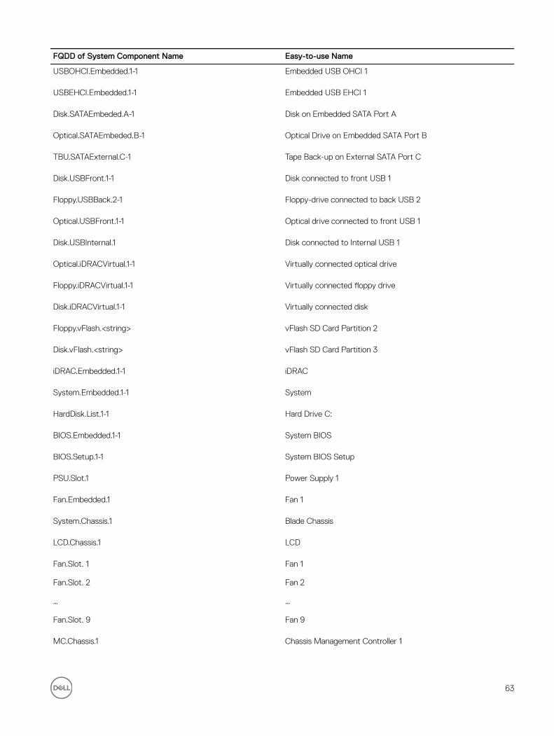
FQDD of System Component Name Easy-to-use Name
USBOHCI.Embedded.1-1 Embedded USB OHCI 1
USBEHCI.Embedded.1-1 Embedded USB EHCI 1
Disk.SATAEmbeded.A-1 Disk on Embedded SATA Port A
Optical.SATAEmbeded.B-1 Optical Drive on Embedded SATA Port B
TBU.SATAExternal.C-1 Tape Back-up on External SATA Port C
Disk.USBFront.1-1 Disk connected to front USB 1
Floppy.USBBack.2-1 Floppy-drive connected to back USB 2
Optical.USBFront.1-1 Optical drive connected to front USB 1
Disk.USBInternal.1 Disk connected to Internal USB 1
Optical.iDRACVirtual.1-1 Virtually connected optical drive
Floppy.iDRACVirtual.1-1 Virtually connected floppy drive
Disk.iDRACVirtual.1-1 Virtually connected disk
Floppy.vFlash.<string> vFlash SD Card Partition 2
Disk.vFlash.<string> vFlash SD Card Partition 3
iDRAC.Embedded.1-1 iDRAC
System.Embedded.1-1 System
HardDisk.List.1-1 Hard Drive C:
BIOS.Embedded.1-1 System BIOS
BIOS.Setup.1-1 System BIOS Setup
PSU.Slot.1 Power Supply 1
Fan.Embedded.1 Fan 1
System.Chassis.1 Blade Chassis
LCD.Chassis.1 LCD
Fan.Slot. 1
Fan.Slot. 2
…
Fan.Slot. 9
Fan 1
Fan 2
…
Fan 9
MC.Chassis.1 Chassis Management Controller 1
63

FQDD of System Component Name Easy-to-use Name
MC.Chassis.2 Chassis Management Controller 2
KVM.Chassis.1 KVM
IOM.Slot.1
…
IOM.Slot.6
IO Module 1
…
IO Module 6
PSU.Slot.1
…
PSU.Slot.6
Power Supply 1
...
Power Supply 6
CPU.Socket.1 CPU 1
System.Modular.2 Blade 2
DIMM.Socket.A1 DIMM A1
64

11Using The System Setup and Boot ManagerSystem Setup enables you to manage your system hardware and specify BIOS-level options.
The following keystrokes provide access to system features during startup:
Keystroke Description
<F2> Opens the System Setup page.
<F10> Enters System Services and starts Lifecycle Controller, which supports systems management features such as operating system deployment, hardware diagnostics, firmware updates, and platform configuration, using a graphical user interface. The feature set available in Lifecycle Controller is determined by the iDRAC license purchased. For more information, see Related Documentation topic.
<F11> Enters the BIOS Boot Manager or the Unified Extensible Firmware Interface (UEFI) Boot Manager, depending on the system's boot configuration.
<F12> Starts Preboot Execution Environment (PXE) boot.
From the System Setup, you can:
• Change the NVRAM settings after you add or remove hardware
• View the system hardware configuration
• Enable or disable integrated devices
• Set performance and power management thresholds
• Manage system security
You can access the System Setup using the:
• Standard graphical browser, which is enabled by default
• Text browser, which is enabled using Console Redirection
To enable Console Redirection, in System Setup, select System BIOS → Serial Communication screen → Serial Communication, select On with Console Redirection.
NOTE: By default, help text for the selected field is displayed in the graphical browser. To view the help text in the text browser, press <F1>.
Choosing The System Boot ModeSystem Setup enables you to specify the boot mode for installing your operating system:
• BIOS boot mode (the default) is the standard BIOS-level boot interface.
65

• UEFI boot mode is an enhanced 64-bit boot interface based on Unified Extensible Firmware Interface (UEFI) specifications that overlays the system BIOS.
You must select the boot mode in the Boot Mode field of the Boot Settings screen of System Setup. Once you specify the boot mode, the system boots in the specified boot mode and you then proceed to install your operating system from that mode. Thereafter, you must boot the system in the same boot mode (BIOS or UEFI) to access the installed operating system. Trying to boot the operating system from the other boot mode will cause the system to halt at startup.
NOTE: Operating systems must be UEFI-compatible to be installed from the UEFI boot mode. DOS and 32-bit operating systems do not support UEFI and can only be installed from the BIOS boot mode.
NOTE: For the latest information on supported operating systems, go to dell.com/ossupport.
Entering System Setup1. Turn on or restart your system.
2. Press <F2> immediately after you see the following message:
<F2> = System Setup
If your operating system begins to load before you press <F2>, allow the system to finish booting, and then restart your system and try again.
Responding To Error Messages
If an error message is displayed while the system is booting, make a note of the message. For more information, see System Error Messages.
NOTE: After installing a memory upgrade, it is normal for your system to display a message the first time you start your system.
Using The System Setup Navigation Keys
Keys Action
Up arrow Moves to the previous field.
Down arrow Moves to the next field.
<Enter> Allows you to type in a value in the selected field (if applicable) or follow the link in the field.
Spacebar Expands or collapses a drop-down menu, if applicable.
<Tab> Moves to the next focus area.
NOTE: For the standard graphics browser only.
<Esc> Moves to the previous page till you view the main screen. Pressing <Esc> in the main screen displays a message that prompts you to save any unsaved changes and restarts the system.
<F1> Displays the System Setup help file.
NOTE: For most of the options, any changes that you make are recorded but do not take effect until you restart the system.
System Setup Options
66

System Setup Main Screen
NOTE: Press <Alt><F> to reset the BIOS or UEFI settings to their default settings.
Menu Item Description
System BIOS This option is used to view and configure BIOS settings.
iDRAC Settings This option is used to view and configure iDRAC settings.
Device Settings This option is used to view and configure device settings.
System BIOS Screen
NOTE: The options for System Setup change based on the system configuration.
NOTE: System Setup defaults are listed under their respective options in the following sections, where applicable.
Menu Item Description
System Information Displays information about the system such as the system model name, BIOS version, Service Tag, and so on.
Memory Settings Displays information and options related to installed memory.
Processor Settings Displays information and options related to the processor such as speed, cache size, and so on.
SATA Settings Displays options to enable or disable the integrated SATA controller and ports.
NOTE: This setting is not available on the PowerEdge R720xd.
Boot Settings Displays options to specify the boot mode (BIOS or UEFI). Enables you to modify UEFI and BIOS boot settings.
Integrated Devices Displays options to enable or disable integrated device controllers and ports, and to specify related features and options.
Serial Communication
Displays options to enable or disable the serial ports and specify related features and options.
System Profile Settings
Displays options to change the processor power management settings, memory frequency, and so on.
System Security Displays options to configure the system security settings like, system password, setup password, TPM security, and so on. It also enables or disables support for local BIOS update, the power and NMI buttons on the system.
Miscellaneous Settings
Displays options to change the system date, time, and so on.
System Information Screen
Menu Item Description
System Model Name Displays the system model name.
System BIOS Version
Displays the BIOS version installed on the system.
System Service Tag Displays the system Service Tag.
67

Menu Item Description
System Manufacturer
Displays the name of the system manufacturer.
System Manufacturer Contact Information
Displays the contact information of the system manufacturer.
Memory Settings Screen
Menu Item Description
System Memory Size
Displays the amount of memory installed in the system.
System Memory Type
Displays the type of memory installed in the system.
System Memory Speed
Displays the system memory speed.
System Memory Voltage
Displays the system memory voltage.
Video Memory Displays the amount of video memory.
System Memory Testing
Specifies whether system memory tests are run during system boot. Options are Enabled and Disabled. By default, the System Memory Testing option is set to Disabled.
Memory Operating Mode
Specifies the memory operating mode. The options available are Optimizer Mode, Advanced ECC Mode, Mirror Mode, Spare Mode, Spare with Advanced ECC Mode, and Dell Fault Resilient Mode. By default, the Memory Operating Mode option is set to Optimizer Mode.
NOTE: The Memory Operating Mode can have different defaults and available options based on the memory configuration of your system.
NOTE: The Dell Fault Resilient Mode establishes an area of memory that is fault resilient. This mode can be used by an operating system that supports the feature to load critical applications or enables the operating system kernel to maximize system availability.
Node Interleaving If this field is Enabled, memory interleaving is supported if a symmetric memory configuration is installed. If Disabled, the system supports Non-Uniform Memory architecture (NUMA) (asymmetric) memory configurations. By default, Node Interleaving option is set to Disabled.
Serial Debug Output By default, it is set to disabled.
Processor Settings Screen
Menu Item Description
Logical Processor Allows you to enable or disable logical processors and display the number of logical processors. If the Logical Processor option is set to Enabled, the BIOS displays all the logical processors. If this option is set to Disabled, the BIOS only displays one logical processor per core. By default, the Logical Processor option is set to Enabled.
QPI Speed Allows you to set the QuickPath Interconnect (QPI) data rate settings. By default, the QPI Speed option is set to Maximum data rate.
NOTE: QPI Speed displays only when both the processors are installed.
68
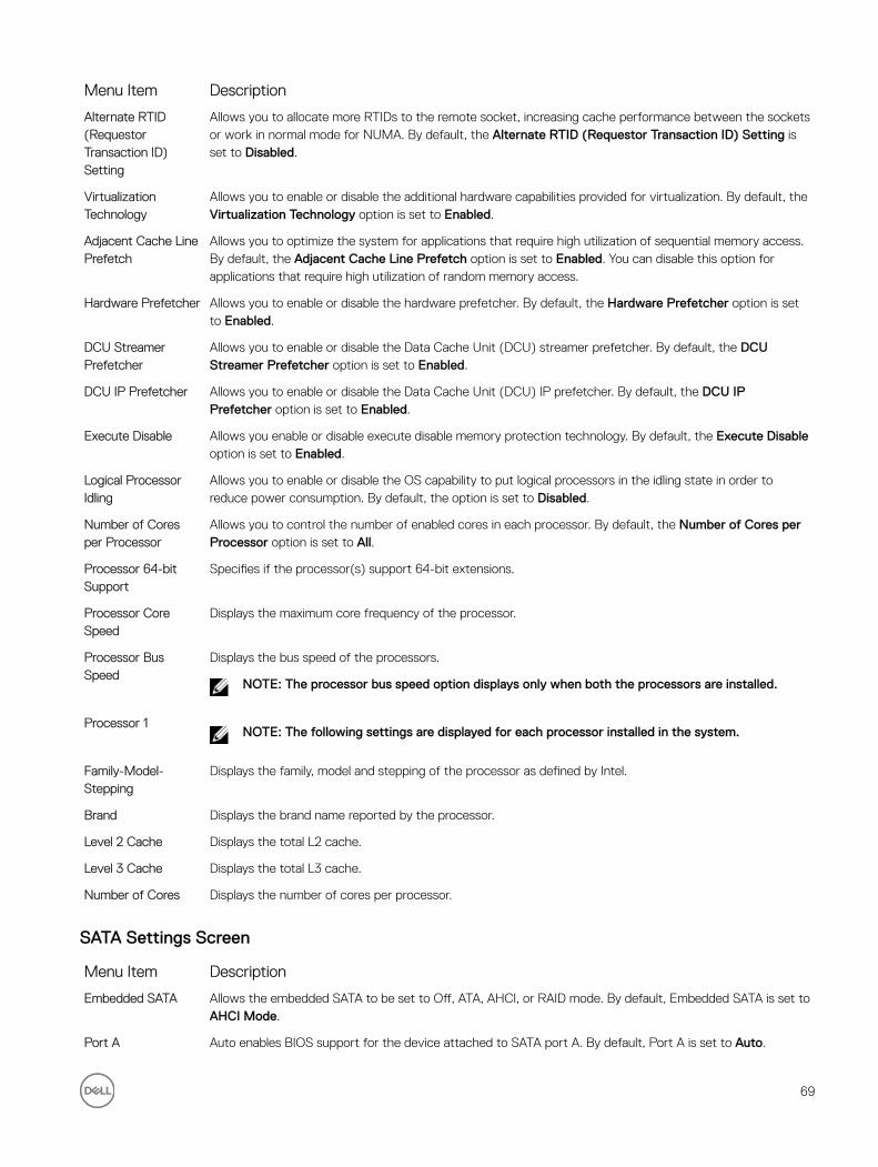
Menu Item Description
Alternate RTID (Requestor Transaction ID) Setting
Allows you to allocate more RTIDs to the remote socket, increasing cache performance between the sockets or work in normal mode for NUMA. By default, the Alternate RTID (Requestor Transaction ID) Setting is set to Disabled.
Virtualization Technology
Allows you to enable or disable the additional hardware capabilities provided for virtualization. By default, the Virtualization Technology option is set to Enabled.
Adjacent Cache Line Prefetch
Allows you to optimize the system for applications that require high utilization of sequential memory access. By default, the Adjacent Cache Line Prefetch option is set to Enabled. You can disable this option for applications that require high utilization of random memory access.
Hardware Prefetcher Allows you to enable or disable the hardware prefetcher. By default, the Hardware Prefetcher option is set to Enabled.
DCU Streamer Prefetcher
Allows you to enable or disable the Data Cache Unit (DCU) streamer prefetcher. By default, the DCU Streamer Prefetcher option is set to Enabled.
DCU IP Prefetcher Allows you to enable or disable the Data Cache Unit (DCU) IP prefetcher. By default, the DCU IP Prefetcher option is set to Enabled.
Execute Disable Allows you enable or disable execute disable memory protection technology. By default, the Execute Disable option is set to Enabled.
Logical Processor Idling
Allows you to enable or disable the OS capability to put logical processors in the idling state in order to reduce power consumption. By default, the option is set to Disabled.
Number of Cores per Processor
Allows you to control the number of enabled cores in each processor. By default, the Number of Cores per Processor option is set to All.
Processor 64-bit Support
Specifies if the processor(s) support 64-bit extensions.
Processor Core Speed
Displays the maximum core frequency of the processor.
Processor Bus Speed
Displays the bus speed of the processors.
NOTE: The processor bus speed option displays only when both the processors are installed.
Processor 1NOTE: The following settings are displayed for each processor installed in the system.
Family-Model-Stepping
Displays the family, model and stepping of the processor as defined by Intel.
Brand Displays the brand name reported by the processor.
Level 2 Cache Displays the total L2 cache.
Level 3 Cache Displays the total L3 cache.
Number of Cores Displays the number of cores per processor.
SATA Settings Screen
Menu Item Description
Embedded SATA Allows the embedded SATA to be set to Off, ATA, AHCI, or RAID mode. By default, Embedded SATA is set to AHCI Mode.
Port A Auto enables BIOS support for the device attached to SATA port A. By default, Port A is set to Auto.
69
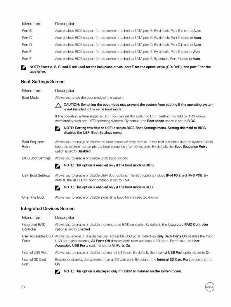
Menu Item Description
Port B Auto enables BIOS support for the device attached to SATA port B. By default, Port B is set to Auto.
Port C Auto enables BIOS support for the device attached to SATA port C. By default, Port C is set to Auto.
Port D Auto enables BIOS support for the device attached to SATA port D. By default, Port D is set to Auto.
Port E Auto enables BIOS support for the device attached to SATA port E. By default, Port E is set to Auto.
Port F Auto enables BIOS support for the device attached to SATA port F. By default, Port F is set to Auto.
NOTE: Ports A, B, C, and D are used for the backplane drives, port E for the optical drive (CD/DVD), and port F for the tape drive.
Boot Settings Screen
Menu Item Description
Boot Mode Allows you to set the boot mode of the system.
CAUTION: Switching the boot mode may prevent the system from booting if the operating system is not installed in the same boot mode.
If the operating system supports UEFI, you can set this option to UEFI. Setting this field to BIOS allows compatibility with non-UEFI operating systems. By default, the Boot Mode option is set to BIOS.
NOTE: Setting this field to UEFI disables BIOS Boot Settings menu. Setting this field to BIOS disables the UEFI Boot Settings menu.
Boot Sequence Retry
Allows you to enable or disable the boot sequence retry feature. If this field is enabled and the system fails to boot, the system reattempts the boot sequence after 30 seconds. By default, the Boot Sequence Retry option is set to Disabled.
BIOS Boot Settings Allows you to enable or disable BIOS Boot options.
NOTE: This option is enabled only if the boot mode is BIOS.
UEFI Boot Settings Allows you to enable or disable UEFI Boot options. The Boot options include IPv4 PXE and IPv6 PXE. By default, the UEFI PXE boot protocol is set to IPv4.
NOTE: This option is enabled only if the boot mode is UEFI.
One-Time Boot Allows you to enable or disable a one-time boot from a selected device.
Integrated Devices Screen
Menu Item Description
Integrated RAID Controller
Allows you to enable or disable the integrated RAID controller. By default, the Integrated RAID Controller option is set to Enabled.
User Accessible USB Ports
Allows you enable or disable the user accessible USB ports. Selecting Only Back Ports On disables the front USB ports and selecting All Ports Off disables both front and back USB ports. By default, the User Accessible USB Ports option is set to All Ports On.
Internal USB Port Allows you to enable or disable the internal USB port. By default, the Internal USB Port option is set to On.
Internal SD Card Port
Enables or disables the system’s internal SD card port. By default, the Internal SD Card Port option is set to On.
NOTE: This option is displayed only if IDSDM is installed on the system board.
70

Menu Item Description
Internal SD Card Redundancy
If set to Mirror mode, data is written on both SD cards. If any one of the SD card fails, data is written to the active SD card. Data from this card is copied to the replacement SD card at the next boot. By default, Internal SD Card Redundancy option is set to Mirror.
NOTE: This option is displayed only if IDSDM is installed on the system board.
Integrated Network Card 1
Allows you to enable or disable the integrated network card 1. By default, the Integrated Network Card 1 option is set to Enabled.
OS Watchdog Timer Allows you to enable or disable the OS watchdog timer. When this field is enabled, the operating system initializes the timer and the OS watchdog timer helps in recovering the operating system. By default, the OS Watchdog Timer option is set to Disabled.
Embedded Video Controller
Allows you to enable or disable the Embedded Video Controller. By default, the embedded video controller is set to Enabled.
SR-IOV Global Enable
Allows you to enable or disable the BIOS configuration of Single Root I/O Virtualization (SR-IOV) devices. By default, the SR-IOV Global Enable option is set to Disabled.
Memory Mapped I/O above 4GB
Allows you to enable support for PCIe devices that require large amounts of memory. By default, the option is set to Enabled.
Slot Disablement Allows you to enable or disable available PCIe slots on your system. The Slot Disablement feature controls the configuration of PCIe cards installed in the specified slot.
CAUTION: Slot disablement must be used only when the installed peripheral card is preventing booting into the Operating System or causing delays in system startup. If the slot is disabled, both the Option ROM and UEFI driver are disabled.
Serial Communications Screen
Menu Item Description
Serial Communication
Allows you to select serial communication devices (Serial Device 1 and Serial Device 2) in the BIOS. BIOS console redirection can also be enabled and the port address can be specified. By default, Serial Communication option is set to On without Console Redirection.
Serial Port Address Allows you to set the port address for serial devices. By default, the Serial Port Address option is set to Serial Device 1=COM2, Serial Device 2=COM1.
NOTE: Only Serial Device 2 can be used for Serial Over LAN (SOL). To use console redirection by SOL, configure the same port address for console redirection and the serial device.
External Serial Connector
Allows you to associate the external serial connector to serial device 1, serial device 2, or remote access device. By default, the External Serial Connector option is set to Serial Device1.
NOTE: Only Serial Device 2 can be used for SOL. To use console redirection by SOL, configure the same port address for console redirection and the serial device.
Failsafe Baud Rate Displays the failsafe baud rate for console redirection. The BIOS attempts to determine the baud rate automatically. This failsafe baud rate is used only if the attempt fails and the value must not be changed. By default, the Failsafe Baud Rate option is set to 11520.
Remote Terminal Type
Allows you to set the remote console terminal type. By default, the Remote Terminal Type option is set to VT 100/VT 220.
Redirection After Boot
Allows you to enable or disable to the BIOS console redirection when the operating system is loaded. By default, the Redirection After Boot option is set to Enabled.
71

System Profile Settings Screen
Menu Item Description
System Profile Allows you to set the system profile. If you set the System Profile option to a mode other than Custom, the BIOS automatically sets the rest of the options. You can only change the rest of the options if the mode is set to Custom. By default, the System Profile option is set to Performance Per Watt Optimized (DAPC). DAPC is Dell Active Power Controller.
NOTE: The following parameters are available only when the System Profile is set to Custom.
CPU Power Management
Allows you to set the CPU power management. By default, the CPU Power Management option is set to System DBPM (DAPC). DBPM is Demand-Based Power Management.
Memory Frequency Allows you to set the memory frequency. By default, the Memory Frequency option is set to Maximum Performance.
Turbo Boost Allows you to enable or disable the processor to operate in turbo boost mode. By default, the Turbo Boost option is set to Enabled.
C1E Allows you to enable or disable the processor to switch to a minimum performance state when it is idle. By default, the C1E option is set to Enabled.
C States Allows you to enable or disable the processor to operate in all available power states. By default, the C States option is set to Enabled.
Monitor/Mwait Allows you to enable Monitor/Mwait instructions in the processor. By default, the Monitor/Mwait option is set to Enabled for all system profiles, except Custom.
NOTE: This option can be disabled only if the C States option in Custom mode is disabled.
NOTE: When C States is enabled in Custom mode, changing the Monitor/Mwait setting does not impact system power/performance.
Memory Patrol Scrub
Allows you to set the memory patrol scrub frequency. By default, the Memory Patrol Scrub option is set to Standard.
Memory Refresh Rate
Allows you to set the memory refresh rate. By default, the Memory Refresh Rate option is set to 1x.
Memory Operating Voltage
Allows you to set the DIMM voltage selection. When set to Auto, the system automatically sets the system voltage to the optimal setting based on the DIMM capacity and the number of DIMMs installed. By default, the Memory Operating Voltage option is set to Auto.
Collaborative CPU Performance Control
When set to Enabled, the CPU power management is controlled by the OS DBPM and the System DBPM (DAPC). By default, the option is set to Disabled.
System Security Screen
Menu Item Description
Intel AES-NI Improves the speed of applications by performing encryption and decryption using the Advanced Encryption Standard Instruction Set and is set to Enabled by default.
System Password Allows you to set the system password. This option is set to Enabled by default and is read-only if the password jumper is not installed in the system.
Setup Password Allows you to set the setup password. This option is read-only if the password jumper is not installed in the system.
Password Status Allows you to lock the system password. By default, the Password Status option is set to Unlocked.
72

Menu Item Description
TPM Security Allows you to control the reporting mode of the Trusted Platform Module (TPM). By default, the TPM Security option is set to Off. You can only modify the TPM Status, TPM Activation , and Intel TXT fields if the TPM Status field is set to either On with Pre-boot Measurements or On without Pre-boot Measurements.
TPM Activation Allows you to change the operational state of the TPM. By default, the TPM Activation option is set to No Change.
TPM Status Displays the TPM status.
TPM ClearCAUTION: Clearing the TPM results in the loss of all keys in the TPM. The loss of TPM keys may affect booting to the operating system.
Allows you to clear all the contents of the TPM. By default, the TPM Clear option is set to No.
Intel TXT Allows you to enable or disable Intel Trusted Execution Technology (TXT). To enable Intel TXT, Virtualization Technology must be enabled and TPM Security must be Enabled with Pre-boot measurements. By default, the Intel TXT option is set to Off.
BIOS Update Control
Allows you to update the BIOS using either DOS or UEFI shell-based flash utilities. For environments that do not require local BIOS updates, it is recommended to set this option to Disabled. By default, the BIOS Update Control option is set to Unlocked.
NOTE: BIOS updates using the Dell Update Package are not affected by this option.
Power Button Allows you to enable or disable the power button on the front of the system. By default, the Power Button option is set to Enabled.
NMI Button Allows you to enable or disable the NMI button on the front of the system. By default, the NMI Button option is set to Disabled.
AC Power Recovery Allows you to set how the system reacts after AC power is restored to the system. By default, the AC Power Recovery option is set to Last.
AC Power Recovery Delay
Allows you to set how the system supports staggering of power up after AC power is restored to the system. By default, the AC Power Recovery Delay option is set to Immediate.
User Defined Delay (60s to 240s)
Allows you to set the User Defined Delay when the User Defined option for AC Power Recovery Delay is selected.
Miscellaneous Settings
Menu Item Description
System Time Allows you to set the time on the system.
System Date Allows you to set the date on the system.
Asset Tag Displays the asset tag and allows you to modify it for security and tracking purposes.
Keyboard NumLock Allows you to set whether the system boots with the NumLock enabled or disabled. By default the Keyboard NumLock is set to On.
NOTE: This option does not apply to 84-key keyboards.
Report Keyboard Errors
Allows you to set whether keyboard-related error messages are reported during system boot. By default, the Report Keyboard Errors option is set to Report.
F1/F2 Prompt on Error
Allows you to enable or disable the F1/F2 prompt on error. By default, F1/F2 Prompt on Error is set to Enabled.
73
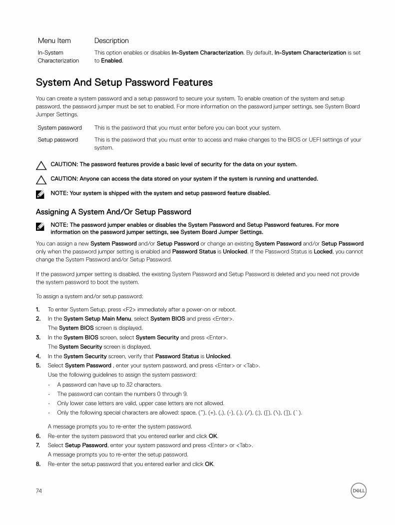
Menu Item Description
In-System Characterization
This option enables or disables In-System Characterization. By default, In-System Characterization is set to Enabled.
System And Setup Password FeaturesYou can create a system password and a setup password to secure your system. To enable creation of the system and setup password, the password jumper must be set to enabled. For more information on the password jumper settings, see System Board Jumper Settings.
System password This is the password that you must enter before you can boot your system.
Setup password This is the password that you must enter to access and make changes to the BIOS or UEFI settings of your system.
CAUTION: The password features provide a basic level of security for the data on your system.
CAUTION: Anyone can access the data stored on your system if the system is running and unattended.
NOTE: Your system is shipped with the system and setup password feature disabled.
Assigning A System And/Or Setup Password
NOTE: The password jumper enables or disables the System Password and Setup Password features. For more information on the password jumper settings, see System Board Jumper Settings.
You can assign a new System Password and/or Setup Password or change an existing System Password and/or Setup Password only when the password jumper setting is enabled and Password Status is Unlocked. If the Password Status is Locked, you cannot change the System Password and/or Setup Password.
If the password jumper setting is disabled, the existing System Password and Setup Password is deleted and you need not provide the system password to boot the system.
To assign a system and/or setup password:
1. To enter System Setup, press <F2> immediately after a power-on or reboot.
2. In the System Setup Main Menu, select System BIOS and press <Enter>.
The System BIOS screen is displayed.
3. In the System BIOS screen, select System Security and press <Enter>.
The System Security screen is displayed.
4. In the System Security screen, verify that Password Status is Unlocked.
5. Select System Password , enter your system password, and press <Enter> or <Tab>.
Use the following guidelines to assign the system password:
• A password can have up to 32 characters.
• The password can contain the numbers 0 through 9.
• Only lower case letters are valid, upper case letters are not allowed.
• Only the following special characters are allowed: space, (”), (+), (,), (-), (.), (/), (;), ([), (\), (]), (`).
A message prompts you to re-enter the system password.
6. Re-enter the system password that you entered earlier and click OK.
7. Select Setup Password, enter your system password and press <Enter> or <Tab>.
A message prompts you to re-enter the setup password.
8. Re-enter the setup password that you entered earlier and click OK.
74

9. Press <Esc> to return to the System BIOS screen. Press <Esc> again, and a message prompts you to save the changes.
NOTE: Password protection does not take effect until the system reboots.
Deleting Or Changing An Existing System And/Or Setup Password
Ensure that the Password jumper is set to enabled and the Password Status is Unlocked before attempting to delete or change the existing System and/or Setup password. You cannot delete or change an existing System or Setup password if the Password Status is Locked.To delete or change the existing System and/or Setup password:
1. To enter System Setup, press <F2> immediately after a power-on or restart.
2. In the System Setup Main Menu, select System BIOS and press <Enter>.
The System BIOS screen is displayed.
3. In the System BIOS Screen, select System Security and press <Enter>.
The System Security screen is displayed.
4. In the System Security screen, verify that Password Status is Unlocked.
5. Select System Password, alter or delete the existing system password and press <Enter> or <Tab>.
6. Select Setup Password, alter or delete the existing setup password and press <Enter> or <Tab>.
NOTE: If you change the System and/or Setup password a message prompts you to re-enter the new password. If you delete the System and/or Setup password, a message prompts you to confirm the deletion.
7. Press <Esc> to return to the System BIOS screen. Press <Esc> again, and a message prompts you to save the changes.
NOTE: You can disable password security while logging on to the system. To disable the password security, turn on or reboot your system, type your password and press <Ctrl><Enter>.
Using Your System Password To Secure Your System
NOTE: If you have assigned a setup password, the system accepts your setup password as an alternate system password.
1. Turn on or reboot your system.
2. Type your password and press <Enter>.
When Password Status is Locked, type the password and press <Enter> when prompted at reboot.
If an incorrect system password is entered, the system displays a message and prompts you to re-enter your password. You have three attempts to enter the correct password. After the third unsuccessful attempt, the system displays an error message that the system has halted and must be powered down.
Even after you shut down and restart the system, the error message is displayed until the correct password is entered.
NOTE: You can use the Password Status option in conjunction with the System Password and Setup Password options to protect your system from unauthorized changes.
Operating With A Setup Password Enabled
If Setup Password is Enabled, enter the correct setup password before modifying most of the System Setup options.
If you do not enter the correct password in three attempts, the system displays the message
Invalid Password! Number of unsuccessful password attempts: <x> System Halted! Must power down.
Even after you shut down and restart the system, the error message is displayed until the correct password is entered. The following options are exceptions:
• If System Password is not Enabled and is not locked through the Password Status option, you can assign a system password.
75
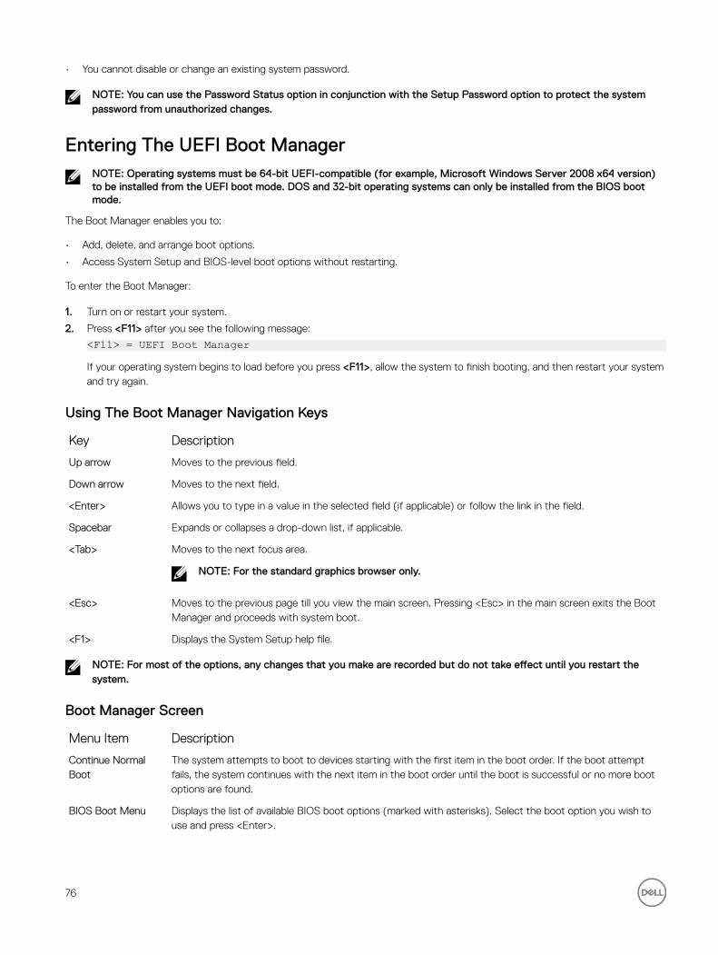
• You cannot disable or change an existing system password.
NOTE: You can use the Password Status option in conjunction with the Setup Password option to protect the system password from unauthorized changes.
Entering The UEFI Boot ManagerNOTE: Operating systems must be 64-bit UEFI-compatible (for example, Microsoft Windows Server 2008 x64 version) to be installed from the UEFI boot mode. DOS and 32-bit operating systems can only be installed from the BIOS boot mode.
The Boot Manager enables you to:
• Add, delete, and arrange boot options.
• Access System Setup and BIOS-level boot options without restarting.
To enter the Boot Manager:
1. Turn on or restart your system.
2. Press <F11> after you see the following message:
<F11> = UEFI Boot ManagerIf your operating system begins to load before you press <F11>, allow the system to finish booting, and then restart your system and try again.
Using The Boot Manager Navigation Keys
Key Description
Up arrow Moves to the previous field.
Down arrow Moves to the next field.
<Enter> Allows you to type in a value in the selected field (if applicable) or follow the link in the field.
Spacebar Expands or collapses a drop-down list, if applicable.
<Tab> Moves to the next focus area.
NOTE: For the standard graphics browser only.
<Esc> Moves to the previous page till you view the main screen. Pressing <Esc> in the main screen exits the Boot Manager and proceeds with system boot.
<F1> Displays the System Setup help file.
NOTE: For most of the options, any changes that you make are recorded but do not take effect until you restart the system.
Boot Manager Screen
Menu Item Description
Continue Normal Boot
The system attempts to boot to devices starting with the first item in the boot order. If the boot attempt fails, the system continues with the next item in the boot order until the boot is successful or no more boot options are found.
BIOS Boot Menu Displays the list of available BIOS boot options (marked with asterisks). Select the boot option you wish to use and press <Enter>.
76

Menu Item Description
UEFI Boot Menu Displays the list of available UEFI boot options (marked with asterisks). Select the boot option you wish to use and press <Enter>. The UEFI Boot Menu enables you to Add Boot Option, Delete Boot Option, or Boot From File.
Driver Health Menu Displays a list of the drivers installed on the system and their health status.
Launch System Setup
Enables you to access the System Setup.
System Utilities Enables you to access the BIOS Update File Explorer, run the Dell Diagnostics program, and reboot the system.
UEFI Boot Menu
Menu Item Description
Select UEFI Boot Option
Displays the list of available UEFI boot options (marked with asterisks), select the boot option you wish to use and press <Enter>.
Add Boot Option Adds a new boot option.
Delete Boot Option Deletes an existing boot option.
Boot From File Sets a one-time boot option not included in the boot option list.
Embedded System ManagementThe Dell Lifecycle Controller provides advanced embedded systems management throughout the server’s lifecycle. The Lifecycle Controller can be started during the boot sequence and can function independently of the operating system.
NOTE: Certain platform configurations may not support the full set of features provided by the Lifecycle Controller.
For more information about setting up the Lifecycle Controller, configuring hardware and firmware, and deploying the operating system, see the Lifecycle Controller documentation at dell.com/support/manuals.
iDRAC Settings UtilityThe iDRAC Settings utility is an interface to setup and configure the iDRAC parameters using UEFI. You can enable or disable various iDRAC parameters using the iDRAC Settings Utility.
NOTE: Accessing some of the features on the iDRAC Settings Utility requires the iDRAC7 Enterprise License upgrade.
For more information on using iDRAC, see the iDRAC7 User's Guide at dell.com/esmmanuals.
Entering The iDRAC Settings Utility
1. Turn on or restart the managed system.
2. Press <F2> during Power-on Self-test (POST).
3. In the System Setup Main Menu page, click iDRAC Settings.
The iDRAC Settings screen is displayed.
77