Dell EMC Unity: Dynamic Pools · taken, the snapshot is an exact copy of the source storage...
30
WHITE PAPER DELL EMC UNITY: DYNAMIC POOLS Overview ABSTRACT This white paper is an introduction to Dynamic Pools. It provides an overview of Dynamic Pool technology, including information of the underlying structures, benefits for using Dynamic Pools, and methods for managing Dynamic Pools. March, 2018
-
Upload
hoanghuong -
Category
Documents
-
view
218 -
download
2
Transcript of Dell EMC Unity: Dynamic Pools · taken, the snapshot is an exact copy of the source storage...

WHITE PAPER
DELL EMC UNITY: DYNAMIC POOLS
Overview
ABSTRACT
This white paper is an introduction to Dynamic Pools. It provides an overview of
Dynamic Pool technology, including information of the underlying structures, benefits for
using Dynamic Pools, and methods for managing Dynamic Pools.
March, 2018

2
The information in this publication is provided “as is.” Dell Inc. makes no representations or warranties of any kind with respect to the
information in this publication, and specifically disclaims implied warranties of merchantability or fitness for a particular purpose.
Use, copying, and distribution of any software described in this publication requires an applicable software license.
Copyright © 2017 Dell Inc. or its subsidiaries. All Rights Reserved. Dell, EMC, and other trademarks are trademarks of Dell Inc. or its
subsidiaries. Other trademarks may be the property of their respective owners. Published in the USA [03/18] [White Paper] [H16289.2]
Dell EMC believes the information in this document is accurate as of its publication date. The information is subject to change without
notice.

3
TABLE OF CONTENTS
EXECUTIVE SUMMARY ...........................................................................................................5
Audience ........................................................................................................................................... 5
Terminology....................................................................................................................................... 5
OVERVIEW ................................................................................................................................6
ARCHITECTURE .......................................................................................................................7
Drives ................................................................................................................................................ 7
Drive Partnership Groups .................................................................................................................. 7
Drive Extents ..................................................................................................................................... 8
Spare Space Extents ......................................................................................................................... 9
RAID Extents ..................................................................................................................................... 9
Dynamic Pool Private RAID Groups and LUNs ............................................................................... 10
Expanding a Dynamic Pool ............................................................................................................. 11
Proactive Copy and Drive Rebuilds ................................................................................................. 13
Wear Balancing Within a Dynamic Pool .......................................................................................... 14
SUPPORTED CONFIGURATIONS ........................................................................................ 14
Supported Drives ............................................................................................................................. 14
Supported RAID Types ................................................................................................................... 15
Supported Stripe Widths ................................................................................................................. 15
Minimum Drive Counts .................................................................................................................... 16
TRADITIONAL POOLS .......................................................................................................... 16
MANAGEMENT ...................................................................................................................... 17
Viewing the Drives Within the System ............................................................................................. 17
Creating a Dynamic Pool ................................................................................................................. 18
Viewing the Properties of a Dynamic Pool ...................................................................................... 23
Expanding a Dynamic Pool ............................................................................................................. 26
INTEROPERABILITY ............................................................................................................. 29
Data at Rest Encryption .................................................................................................................. 29
Import .............................................................................................................................................. 29
Local LUN Move .............................................................................................................................. 29
Replication ...................................................................................................................................... 29

4
CONCLUSION ........................................................................................................................ 30
REFERENCES ........................................................................................................................ 30

5
EXECUTIVE SUMMARY
The Dell EMC™ Unity product line is a simple, easy-to-use, and intelligent storage system which helps meet the needs of IT
professionals in large or small companies. The systems are designed with flash in mind and leverage the latest cloud based data
management, efficiency, rich data services and mobility technologies. The Dell EMC Unity product line comes in a variety of
deployment models from purpose-built all-flash or hybrid configurations to converged infrastructure and even virtual storage appliances.
To further increase the flexibility of configuration options, Dynamic Pools has been introduced.
Dynamic Pools is a Pool technology introduced for All Flash systems in Dell EMC Unity OE version 4.2 and later. Dynamic Pools
replaces the previous Pool technology, now referred to as Traditional Pools, as the default Pool type for All Flash systems. Dynamic
Pools utilize advanced RAID techniques and distributed sparing to offer better storage utilization and more simplified planning than
Traditional Pools. Dynamic Pools provides a number of benefits over Traditional Pools, which are discussed throughout this document.
This white paper provides in-depth information about Dynamic Pools. This information includes the underlying architecture of Dynamic
Pools and all hidden components of the Pool’s structure. Also discussed are the configurations supported by Dynamic Pools, which
outline the drives supported within a Dynamic Pool, the number of drives supported, and the RAID Types and Widths supported.
Information on creating and managing Dynamic Pools is also provided, which can easily be achieved through Unisphere, Unisphere
CLI, and REST API. The interoperability of Dynamic Pools with other software features is also discussed.
AUDIENCE
This white paper is intended for customers, partners, and employees who are planning to utilize Dynamic Pools. It assumes familiarity
with Dell EMC Unity and the management software.
TERMINOLOGY
All Flash Pool – A Pool which contains only Flash Drives.
Block Storage Resources – LUNs, Consistency Groups and VMware VMFS Datastores.
Compression – A data reduction method which reduces the physical amount of storage required to save a dataset.
Consistency Group – A storage instance which contains one or more LUNs within a storage system. Consistency Groups help
organize the storage allocated for a particular host or hosts. Data protection configurations, such as replication and snapshot settings,
on a Consistency Group affect all the LUNs contained in the group, providing ease of management and crash consistency if the LUNs
are dependent on each other.
Data at Rest Encryption (D@RE) – The process of encrypting data and protecting it against unauthorized access unless valid keys
are provided. This prevents data from being accessed and provides a mechanism to quickly crypto-erase data.
Deduplication – A data reduction method which reduces the physical amount of storage required to save a dataset.
Drive extent – A portion of a drive contained within a Dynamic Pool. Each drive extent is used to provide usable capacity to the Pool,
or spare space.
Drive partnership group – A collection of drives of the same drive type which have been combined into a hidden Dynamic Pool object.
The drive partnership group contains a maximum of 64 drives, and is used to provide space to the Pool.
Dynamic Pool – A new Pool type introduced in Dell EMC Unity OE version 4.2 to provide space to storage resources. Dynamic Pools
allow for flexible deployment models, reduced rebuild times and flash wear when compared to Traditional Pools. A Dynamic Pool will be
created when creating a Pool in Unisphere in Dell EMC Unity OE version 4.2 and later. Dynamic Pools are only supported on Dell EMC
Unity All Flash Systems.
Dynamic Pool private RAID group – A hidden Dynamic Pool object created using RAID extents. A Dynamic Pool private LUN is
created on each private RAID group, which is then used to partition space to storage resources created on the Pool.

6
Dynamic Pool private LUN – A hidden Dynamic Pool object created on a Dynamic Pool private RAID group. The private LUN is later
partitioned into 256 MB slices, which are used as the underlying storage objects for storage resources created on the Pool.
File Storage Resources – File Systems (NFS, SMB) and VMware NFS Datastores.
Flash drive (SSD) – A Flash based storage device used to store data.
LUN – A block based storage resource which a user provisions. It represents a SCSI logical unit.
Pool – A set of drives that provide specific storage characteristics for the resources that use them, such as LUNs, VMware Datastores,
and File Systems.
RAID extent – An object created using drive extents to provide RAID protection for the data within the Pool. Once the RAID type and
stripe width (RAID width) for the pool is set, each RAID extent will provide the RAID protection for the Pool. As an example, if the
Dynamic Pool is created with RAID 5 (4+1) protection, a RAID extent will contain 5 drive extents to provide the 4+1 protection.
REST API – An application programming interface that utilizes familiar HTTP operations like GET, POST, and DELETE. REST
architecture includes certain constraints that ensure that different implementations of REST conform to the same guiding principles,
thereby allowing developers the ease of application development when working with different REST API deployments.
Snapshot – A snapshot, also called a Dell EMC Unity Snapshot, is a point-in-time view of a storage resource. When a snapshot is
taken, the snapshot is an exact copy of the source storage resource, and shares all blocks of data with it. As data changes on the
source, new blocks are allocated and written to. Snapshot technology can be used to take a snapshot of a Block or File storage
resource.
Spare space extent – A drive extent reserved as spare space within the Dynamic Pool. Spare space extents are only utilized to
replace extents on a failing or failed drive within the same drive partnership group.
Storage Resource – An addressable and configurable storage instance associated with a specific quantity of storage. LUNs, File
Systems, and VMware Datastores constitute storage resources.
Stripe Width – The stripe width, also known as the stripe RAID width, is the number of drive extents used for the RAID type chosen for
the Pool. For example, a RAID 5 (4+1) RAID extent has a stripe width of 5 (4+1), and therefore contains 5 drive extents.
Traditional Pool – The Pool technology available within Dell EMC Unity systems before Dynamic Pools were released. Traditional
Pools continue to be supported, and can be managed through Unisphere, Unisphere CLI, and REST API. To create a Traditional Pool,
Unisphere CLI or REST API must be used.
Unisphere – A web-based management environment used to create storage resources, configure and schedule protection for stored
data, and manage and monitor other storage operations.
Unisphere CLI (UEMCLI) – The command line interface for managing Dell EMC Unity storage systems.
OVERVIEW
A Pool is a collection of drives within the system arranged into an aggregated group, with some form of RAID protection applied to the
drives to provide redundancy. The capacity within the Pool, less the overhead for the RAID protection selected, can then be used to
provision block, file, or VVol storage resources. Dynamic Pools, released in Dell EMC Unity OE version 4.2 for All Flash systems,
increases the flexibility of configuration options within the system with an entirely redesigned Pool structure. Dynamic Pools replace the
existing Pool technology, now called Traditional Pools, in this release as the default Pool type for All Flash systems, when created
within Unisphere. Dynamic Pools, as with Traditional Pools, can be created, expanded, and deleted, but include other improvements.
Within a Traditional Pool, private Pool RAID groups are created based on the RAID protection and width selected by the user at time of
Pool creation or expansion. These private RAID groups are fixed in width, and drives must be added to the Pool in drive count multiples
which match the stripe width selected. Dynamic Pools eliminates the need to design a Pool based on a multiple of a stripe width. When
creating a Dynamic Pool, once a minimum drive count for a given RAID protection has been selected, the user can select almost any
number of drives to place within the Pool. This allows the user to plan a Pool based on a specific capacity, and not worry about stripe
width based multiples of drives counts. When expanding a Dynamic Pool, as the stripe width multiple does not apply, the user can also
expand by a specific target capacity. In most cases, the user can add a single drive to the Pool to increase its capacity. These features
7
provide flexible deployment models which improves the planning and provisioning process. The total cost of ownership of the
configuration is also reduced as extra drives needed to fulfill a stripe width multiple are eliminated.
Within systems which utilize Traditional Pools, Hot Spares must be included in the configuration. This requirement increases the cost of
a solution for drives that are left unused within the system, and are only utilized when a drive is failing or has failed. For Dynamic Pools,
space is reserved within the Pool to replace drives which may fail or have failed within the Pool. This space is considered overhead,
and is not part of the usable capacity of the Pool. With this, Hot Spares are not required for Dynamic Pools, and all drives within a
storage system can be placed within a Dynamic Pool. To fully utilize the drives within a Dynamic Pool, the user data and space
reserved for drive failures is spread across all drives within the Pool. This helps to spread out application I/O across the drives within
the Pool, and also helps to spread out and mitigate wear across the drives.
As Dynamic Pools are created without using discreet groups of drives, rebuild operations are completely different than rebuilds
occurring within a Traditional Pool. When a drive is failing or has failed with a Traditional Pool, a Hot Spare is engaged and used to
replace the bad drive. This replacement is one-to-one, and the speed of the proactive copy or rebuild operation is limited by the fixed
width of the private RAID group and the single targeted Hot Spare. With Dynamic Pools, regions of RAID as well as regions within the
Pool which will be utilized for drive replacement are spread across the drives within the Pool. In this design, multiple regions of a failing
or failed drive can be rebuilt simultaneously. As the space for the replacement are spread across the drives in the Pool, the proactive
copy or rebuild operations are also targeted to more than one drive. With these features, the amount of time to replace a failed drive is
significantly reduced.
In the following sections of this document Dynamic Pools will be discussed in further detail.
ARCHITECTURE
The following section covers the underlying architecture of Dynamic Pools. Each of the following subsections outline a building block of
the overall Dynamic Pool structure. While there are many elements to Dynamic Pools, most of the following topics are hidden to the
user in Unisphere, Unisphere CLI, and REST API. They are only discussed to provide insight into the underlying components of
Dynamic Pools. When creating or expanding a Dynamic Pool, the user needs to only determine how many drives to utilize to attain the
usable capacity they require.
DRIVES
A Pool is a set of drives that provide specific storage characteristics for storage resources created on the Pool to utilize. A typical All
Flash system contains either SAS Flash 3 or SAS Flash 4 drives of the same capacity which are used to create Pools within the
system. With Dynamic Pools, a drive is the most basic part of the Pool. Once a Pool has been created, other Dynamic Pool structures
are created on the drives to provide the usable capacity to the user, and provide fault tolerance.
DRIVE PARTNERSHIP GROUPS
When a Dynamic Pool is created or expanded, the selected drives are placed into drive partnership groups. A drive partnership group is
a group of drives of the same drive type which have been combined into a hidden Dynamic Pool object. The number of drives placed in
each group directly depends on the number and type of drives selected at Pool creation, or later when the Pool is expanded. A
Dynamic Pool always includes at least 1 drive partnership group, and each drive within a Dynamic Pool can only be part of a single
drive partnership group. A drive will never change the drive partnership group it is part of for the life of the Pool.
Each drive partnership group can only contain a single drive type, though different sizes of a particular drive type can be mixed within
the group. Figure 1 below is an example of a Dynamic Pool created with different drive types, and different drive sizes. In this example,
all SAS Flash 3 drives are placed into a single drive partnership group, while all SAS Flash 4 drives are placed into their own drive
partnership group. A typical All Flash configuration usually only contains a single drive type and size, but Dynamic Pools does allow for
different types of drives and sizes to be mixed.
8
Figure 1. Drive partnership group example with SAS Flash 3 and SAS Flash 4 drives.
The maximum number of drives contained within a drive partnership group is 64. When more drives of the same type are included in
the Pool, more drive partnership groups are created. Each drive partnership group is started with a minimum number of drives, which is
controlled by the RAID type and stripe width of the Pool. Once the RAID type and stripe width are set for a particular drive type, all drive
partnership groups containing that type of drive will use those settings. When a drive partnership group is full, another minimum number
of drives is needed to create the next drive partnership group with the same RAID type and stripe width. This topic is covered in further
detail in the Supported Configurations section of this paper.
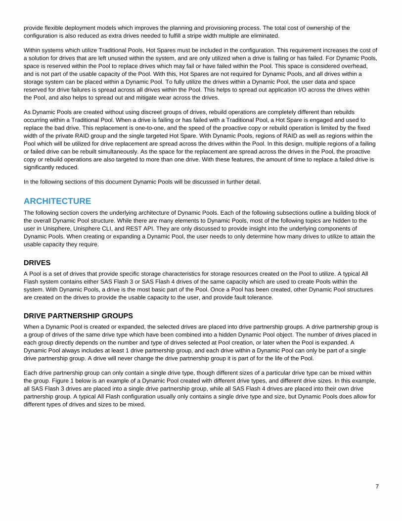
Figure 2 below is an example of multiple Dynamic Pools and drive partnership groups. In the left image, the Dynamic Pool has been
created with only 6 drives of the same type. All of these drives are placed into a single drive partnership group at time of Pool creation.
The middle image is a Pool which contains 64 drives of the same type. The Pool may have been created with 64 drives, or was created
with less drives and later expanded. As the total number of drives is 64, they are all placed into a single drive partnership group, and
the group is considered full. The right image is an example of a Dynamic Pool which contains 70 drives. As a drive partnership group is
considered full at 64 drives, the remaining 6 drives are placed in a new drive partnership group. As with the middle Pool, this Pool may
have been created using 70 drives, or was expanded after creation to reach this drive count.
Figure 2. Drive partnership group example.
The drive partnership group within a Dynamic Pool is used to limit the amount of drives other Dynamic Pool objects can cross. These
objects include drive extents, RAID extents, and spare space extents, and Dynamic Pool private RAID groups, all of which are
explained later in the Architecture section of this paper. This level of fencing ensures the data is not spread across a large amount of
drives, which can increase the risk of encountering multiple drive failures which could degrade or break the RAID protection selected.
DRIVE EXTENTS
A drive extent within a Dynamic Pool is simply a portion of a drive that is GBs in size. The size of each extent is fixed for each drive
type, which can either be SAS Flash 3 or SAS Flash 4 within an All Flash system. After a Dynamic Pool has been created on the
system, each drive within a Dynamic Pool is partitioned into drive extents. The number of extents created on each drive directly
depends on the drive’s type, and the size of the drive. Each extent within a drive will either be used to store user data, or be reserved
as space used to replace a failing or faulted drive within the Pool. Figure 3 below shows two drives, a 400GB SAS FLASH 3 drive and
an 800GB SAS Flash 3 drive, partitioned into drive extents. As all drive extents for this drive type are equal in size, the number of
extents created on the 800GB drive is double what is created on the 400GB drive.

9
Figure 3. Drive extent example with SAS Flash 3 drives.
SPARE SPACE EXTENTS
Unlike Traditional Pools, Dynamic Pools do not require dedicated Hot Spare drives. Instead, space within each Pool is reserved and
can only be used to replace a failing or failed drive. After a Dynamic Pool is created and the drives are partitioned into drive extents, a
number of drive extents are reserved and marked as spare space extents. The number of spare space extents reserved within a
Dynamic Pool directly depends on the size of the drives and the number of drives within the Pool. The amount of spare space is slightly
higher than 1 drive worth of spare space extents for every 31 drives of a specific type within the Pool. The amount of spare space
reserved always ensures that the drive with the largest usable capacity within the Pool can be replaced with the spare space extents
remaining within the Pool.
Spare space is counted as part of a Pool’s overhead, as with RAID overhead, and therefore is not reported to the user. Spare space is
also not part of the usable capacity within the Pool for user data. If a Pool were to become full and a drive failure is seen, there would
still be spare space extents within the Pool to complete the rebuild operation. The amount of spare space within the Pool is not user
configurable, and is reserved at the time of Pool creation, and when expanding a Pool. When a drive count crosses the 1 for 31 mark, a
drive worth of extents is reserved from the additional capacity being added to the Pool. When expanding a Pool in Unisphere in this
instance, the amount of usable capacity would simply show less than that total amount of drive capacity being added to the Pool.
Figure 4 below shows an example of a 6 drive Dynamic Pool. Each drive extent in this example is marked with a “Dx DE y” label
signifying which drive and which extent it is, such as D1 DE 1 (Drive 1 Drive Extent 1). At time of creation, a number of extents on each
drive are reserved as spare space extents, denoted in the figure below as “Spare”. As shown below, spare space extents are evenly
spread across the drives within the Pool. For demonstration purposes, all spare space extents are shown at the end of usable capacity
of each drive. This is not necessarily the way spare space extents will be allocated by the Dynamic Pool algorithms.
Figure 4. Spare space example within a 6 drive Dynamic Pool.
RAID EXTENTS
After spare space extents are reserved within the Dynamic Pool, RAID extents are created with the remaining drive extents. A RAID
extent is a collection of drive extents which complete the stripe width chosen for a particular RAID type. For example, if RAID 5 was
selected as the RAID type, and 4+1 was selected as the stripe width for the Pool, the RAID extent would contain 5 drive extents (4+1).
One for each element of the stripe width. The RAID extent provides RAID protection for user data stored within the Dynamic Pool, and

10
is later used to provide usable capacity to the Pool for storage resource creation. A single RAID extent cannot contain two drive extents
from a single drive for protection purposes. Also, RAID extents must contain drive extents from only a single drive partnership group.
Figure 5 below shows an example of a Dynamic Pool created with 6 drives, assuming that RAID 5 (4+1) has been selected. In this
example, a number of extents have already been reserved as spare space extents, and the first 3 RAID extents are shown. Each RAID
extent in this example contains 5 drive extents, due to the 4+1 stripe width. The 5 drive extents are selected from the drives within the
drive partnership group, and no 2 extents are selected from the same drive. For ease of illustration, the drive extents selected are in
order across the drives within the Pool. Within a real system, the Dynamic Pool algorithm will select drive extents from different drives
seemingly at random within the drive partnership group.
Figure 5. RAID extent example.
DYNAMIC POOL PRIVATE RAID GROUPS AND LUNS
Within a Pool on a Dell EMC Unity system, whether Traditional or Dynamic, exists one or more private RAID groups and a single
private LUN created on each. These objects, as the names suggest, are underlying components of the system that are not shown via
Unisphere, CLI, or REST API. The private RAID group is used to provide space to the private LUN, which provides space in the form of
256 MB slices to the user for storage resource allocation. In a Traditional Pool, the private RAID group is created by combining a
number of drives into a physical RAID group within the system, whose RAID protection and width matches the settings chosen at time
of creation or Pool expansion. In the case of Dynamic Pools, the private RAID group concept and the creation of the private LUN and
256 MB slices on top of the usable capacity remain the same. What is different is how space is provided to the private RAID group.
Within Dynamic Pools, a private RAID group is created using a combination of RAID extents. Depending on the number of drives
selected at time of Pool creation or expansion, the Dynamic Pool software will determine how many RAID extents and private RAID
groups to create. Later, a single private LUN is created on each private RAID group. Figure 6 below shows an example of a Dynamic
Pool and the private RAID groups created in it. In this example, the Dynamic Pool consists of 6 drives of the same size and type. Once
the drives extents are combined into RAID extents, the RAID extents are added to Dynamic Pool private RAID groups. In this example
the number of RAID extents contained in each private RAID group are equal, though this is not always the case. For illustration
purposes, the RAID extents were created by taking drive extents in order across the drives, though this is not necessarily the order the
Dynamic Pool algorithm will take them.
Figure 6. Dynamic Pool private RAID group example.
11
After RAID extents are assigned to a private RAID group, the usable space for each extent is combined into a private LUN. The private
LUN is later carved into 256 MB slices for storage resource allocation. To ensure user data is spread across as many drives possible,
the RAID extents are broken into pieces, a few MBs in size, and combined through concatenation into the private LUN. This ensures
that each 256 MB slice contains pieces of multiple RAID extents within the private RAID group.
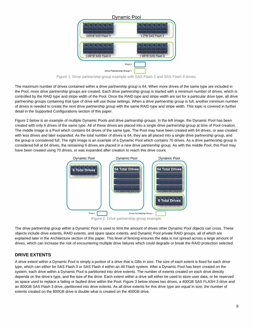
Figure 7 below is an example of a private LUN created using RAID extents within a private RAID Group. Pieces of each RAID extent
are concatenated together to form the useable capacity of the private LUN. Later, the private LUN is carved into 256 MB slices, which
are used to provide space for storage resources created on the Dynamic Pool. The benefit of allocating space in this manner is that a
single 256 MB slice worth of data is spread across multiple RAID extents. These RAID extents may be spread across all drives within a
single drive partnership group, which can contain up to 64 drives. This spreading out of data helps to not only spread the workload
throughout the drive partnership group, but also spread out wear as much as possible due to the workload. When creating a storage
resource on a Dynamic Pool, such as a LUN or file system, 256 MB slices for the resource will be taken from the different private LUNs
within the Dynamic Pool to further spread out the workload.
Figure 7. Dynamic Pool RAID extent and private LUN example.
EXPANDING A DYNAMIC POOL
To provide flexibility, a Dynamic Pool can be expanded up to the system limits by 1 or more drives under most circumstances. The only
time an expansion is not allowed is if the number of drives being added is more than enough to fill a drive partnership group, but not
enough to also fulfill the minimum drive requirements to start another. In this instance, either less drives or more drives need to be
added to the Pool. This topic is covered in further detail in the Supported Configurations section of this paper.
When a single drive is successfully added to a Dynamic Pool, the space will either be added as usable capacity for storage resources
or spare space. The drive’s capacity will only be added as spare space if the requirement for spare space extents has been increased.
In this instance, an additional drive needs to be added to the Pool to increase the usable capacity within the Pool. To make the usable
capacity available to the Pool, a rebalance of drive extents within the Dynamic Pool drive partnership group must occur. This process is
necessary as RAID extents cannot include drive extents entirely from the newly added drive. In the background, drives extents are
relocated throughout the drive partnership group. During this time CPU resources are utilized for relocation operations, but priority is
always given to user I/O and the relocation process will throttle to not impact performance. This operation does take time to complete.
The capacity will be available within the Pool once the job completes.
Figure 8 below shows an example of expanding a Dynamic Pool by a single drive which does not increase the spare space
requirement. If the spare space requirement was to increase, a drive extent relocation would still occur and spare space extents would
be spread out across the drives within the drive partnership group. In this example, drive extents are first created on the newly added
drive. As no two extents from a drive can be placed into a RAID extent, the drive extents must be rebalanced. To rebalance drive
extents, the Dynamic Pool algorithms will first identify a drive extent to relocate, and a location on the new drive to place it. This
movement is a copy operation, which frees the original location of the drive extent for use. This process is repeated until all new space
is spread across the drives within the drive partnership group.

12
Figure 8. Dynamic Pool single drive expansion example. Additional drive added.
Figure 9 below shows the state of the drive partnership group after the relocation of drive extents has occurred. Used drive extents from
various drives within the drive partnership group have been relocated to the newly added drive to free space. At this point, free drive
extents from different drives can be combined into RAID extents, and a new private Dynamic Pool RAID group and LUN will be created.
Once this process completes, the usable capacity of the Pool will be increased for use.
Figure 9. Dynamic Pool single drive expansion example. Rebalance complete.
When the number of drives added to the Pool matches the stripe width plus 1 drive and the spare space amount does not increase,
space can quickly be made available to the Pool. In this situation, drive extents, RAID extents, and the private RAID group and LUN
can quickly be created on the new drives, and no upfront relocations need to occur. After the space is made available to the Pool, a
background relocation process is started to spread used and spare space extents out across the drives within the drive partnership
group. This process ensures that application workloads, wear, and spare space are spread out among the drives within the drive
partnership group.
Figure 10 below shows an example of a Pool created with 6 drives. For this example assume the Pool is a RAID 5 (4+1), and after
some period of time the Pool is expanded using an additional 6 drives, bringing the total drive count to 12. This additional drive count
matches the current stripe width of 4+1 plus an additional drive. In this instance, All Dynamic Pool components can quickly be created
on the new drives, and space can be made available to the Pool. After this is done, drive extents are relocated across the existing and
new drives to spread out the spare space extents, as well as the drive extents containing user data. This operation is a background
process, which will throttle as needed as to not impact application I/O.

13
Figure 10. Dynamic Pool multiple drive expansion example.
When a drive expansion process is started, a job is created in the system and is run as a background task. The additional capacity is
not available within the Dynamic Pool being expanded until the process completes. The job’s progress can be tracked in Unisphere by
reviewing the Jobs page, or through Unisphere CLI or REST API. The amount of time the overall expansion process takes, directly
depends on the number of drives being added, and the size and type of drives.
PROACTIVE COPY AND DRIVE REBUILDS
As mentioned previously, Dynamic Pools contain spare space extents to replace a drive going bad or a failed drive within the Pool. The
spare space extents can either be used as a target of a proactive copy operation, or a rebuild of a degraded RAID extent due to a
faulted drive. In either case, spare space extents are used within the same drive partnership group as the bad drive.
The Dell EMC Unity software tracks all drive errors, and if a drive is receiving errors above the Dell EMC Unity OE’s internal thresholds,
a proactive copy operation may be started. A proactive copy operation is the process of copying data from a drive going bad to a new
location. Once the copy operation completes, the drive will be failed by the software. As this is a copy operation, the proactive copy
completes much faster than a full drive rebuild. In the case of Dynamic Pools, a proactive copy operation will copy a drive extent from
the failing drive to a spare space extent within the Pool. During this operation, the Dell EMC Unity OE ensures the destination drive for
each RAID extent does not already contain an extent from the same RAID extent. To ensure the proactive copy operation completes
quickly, multiple drives extents can be copied from the failing drive at the same time. The target destination extents for proactive copy
operations are also not selected from the same destination drive, which also spreads out the workload.
If a drive were to fail before it could be proactively copied, a rebuild operation must occur. Within a Dynamic Pool, a failed drive rebuild
occurs by rebuilding the degraded RAID extents within the drive partnership group. A RAID extent is considered degraded when at
least one of the drive extents within the RAID extent is no longer available. During the rebuild of a RAID extent, the remaining drive
extents within the RAID extent are used to rebuild the missing drive extent to a spare space extent. Once complete, the spare space
extent becomes part of the RAID extent and the RAID extent is no longer degraded. As the various RAID extents needing to be rebuilt
and spare space extents are spread across many drives within the drive partnership group, many drives are engaged to complete the
rebuild operations.
The number of drive failures that can be tolerated at the same time within a Dynamic Pool depends on the RAID protection and the
location of the failures within the Pool. For all RAID protections, if single drive failure occurs in different drive partnership groups, the
rebuild operations can occur in parallel if enough spare space is present within the drive partnership groups the drives have failed in.
For RAID 5, as long as two failures are not sustained within a single RAID extent, data access will remain available. For RAID 6, two
failures can occur within a single RAID extent without causing a data unavailable situation. Multiple drives within a single RAID 6 RAID
extent can be rebuilt at the same time if enough spare space extents exist within the drive partnership group to rebuild both drives. For
RAID 1/0, multiple failures can occur within the same RAID extent as long as a primary drive and its mirror are not lost within a single
mirrored pair.
After the proactive copy or RAID extent rebuilds complete, the failed drive must be replaced in the system. At this time, the number of
spare space extents has been reduced within the drive partnership group due to the failed drive and rebuild operations. If a free drive
exists within the system, and it is the same size or larger and the same drive type as the failed drive, it will be consumed by the
Dynamic Pool to replace the missing spare space extents. This operation closely resembles a single drive expansion, and the spare
space extents will be rebalanced across the drives within the drive partnership group. Once the failed drive is replaced, it will be left free
within the system. If no free drives exist within the system, once the failed drive has been replaced, the new drive will be consumed by
the Dynamic Pool and the rebalance of spare space extents will occur.

14
WEAR BALANCING WITHIN A DYNAMIC POOL
Within Dell EMC Unity storage systems, managing wear within Flash drives is crucial to extending the lifespan of the drives. Due to
data access patterns and end user applications, certain areas within a LUN, file system, VMware Datastore, or other storage resource
may have hotspots of activity. If this activity consists of writes, certain areas of particular drives may be targeted, which may increase
the wear of the drives. Internally, all Flash drives used within the storage systems have spare cells to manage wear. Dell EMC Unity
systems include additional wear mitigation techniques to help extend the lifespan of Flash drives.
As outlined in the previous sections, Dynamic Pools have been designed to spread out workloads and wear as evenly as possible.
First, Dynamic Pools do not require Hot Spares, like Traditional Pools. These drives are engaged and utilized within the Pool. When
creating a Dynamic Pool, user data is spread across all drives as much as possible. When expanding a Dynamic Pool, user data again
is spread out as evenly as possible to distribute customer workloads and wear as much as possible.
Wear is also managed and mitigated across drive partnership groups within a Dynamic Pool. If a certain drive partnership group is
wearing faster than another, 256 MB slices can be moved from one drive partnership group to another. This migration of data then
moves the workload targeted at that data within the 256 MB slice to a new location. What this also means is that wear balancing is not
done within a drive partnership group, as moving data within a drive partnership group actually causes more wear, as the data is being
moved within the same set of drives.
If a drive is close to the end of its usable life based on wear, a proactive copy operation may be started by the system to replace the
worn drive. This proactive copy does not copy drive extents within the drive to spare space extents within the Pool, but rather to a free
drive within the system if available. After the proactive copy operation completes, the drive is failed, an alert is generated, a call home is
initiated, and the drive should be replaced. The proactive copy to spare space extents within the drive partnership group is not done
because it would only increase the wear on the drives in the group, which may have the same amount of wear as the drive being
replaced. If a valid spare is not available, no proactive copy operation is completed.
In Dell EMC Unity OE version 4.2 and later, system alert messages are sent at 180, 90, and 30 days before a Flash drive is expected to
reach 100% wear. At the 60 days mark, Dell EMC is notified via call home that the drive may reach 100% wear, and a replacement is
required. These alerts are generated for each individual drive.
SUPPORTED CONFIGURATIONS
Before creating a Dynamic Pool, there are a number of items to consider. These include, but are not limited to, the overall size of the
Pool, which drive type and how many drives to use, and the data protection scheme. The following sections outline the Dynamic Pool
supported configurations and background information you need to know when creating and expanding a Dynamic Pool.
SUPPORTED DRIVES
Dell EMC Unity All Flash storage systems support SAS Flash 3 and SAS Flash 4 Flash drives in a variety of size options. Choosing
between the options available depends what needs to be achieved in the solution. If density is the main concern, then utilizing a small
amount of larger drives may be preferable. If performance is the main concern, then using a larger count of smaller drives may be
selected. In most cases, a balance of the overall footprint of the system, performance, and overall cost of the solution is factored into
the decision.
In a typical configuration for a Dell EMC Unity All Flash system, all of the drives within the system are the same size and type. A system
containing different drive sizes or types typically occurs when additional drives are purchased to expand the capacity of an All Flash
system. Dynamic Pools support mixing different drive sizes and types within a single Pool. This allows flexibility in the solution when
only drives of a different size or type are available, and additional capacity is needed. Within the Pool, SAS Flash 3 and SAS Flash 4
drives cannot exist within the same drive partnership group. Each drive type will be subject to the stripe width and minimum drive count
requirements which will be explained later.
Mixing different drive sizes of the same type is supported within a Dynamic Pool, and the drives will be placed within the same drive
partnership group. This may occur when a Pool’s capacity is critically low and the Pool must be expanded to increase the capacity, or a
spare of the same size is not available. When this occurs, there are situations where the entire capacity of the largest drive(s) may not
be usable. This unusable space is not reported to the user. The entire capacity of a particular drive size is only available when the drive
count within the drive partnership group for the drive in question matches or exceeds the stripe width plus one drive. It is not
recommended to mix different size drives of the same type for this reason, unless an adequate number of drives are available to meet
or exceed the stripe width plus one drive requirement.

15
Figure 11 below shows an example of a Dynamic Pool created with 5x 400 GB drives and 1x 800 GB Flash drive. Assume that this is a
RAID 5 Pool with a stripe width of 4+1. In this example, many of the drive extents on the 800 GB drive cannot be used. These drive
extents are outlined in red.
Figure 11. Dynamic Pool mixing drive sizes. Space unavailable for use.
Figure 12 below shows an example of a Dynamic Pool created as a RAID 5 Pool with a stripe width of 4+1. In this example all drive
extents are available for use. This Pool may have been created this way, or the Pool shown in Figure 11 above was expanded with
additional 800 GB drives to recover the missing space. In either case, all drive extents are available for use, and can be provisioned as
spare space extents or RAID extents. If the last 800 GB drive within the example below was a 1.6 TB drive of the same drive type, then
only 800 GBs of space would be usable.
Figure 12. Dynamic Pool mixing drive sizes. Space available for use.
SUPPORTED RAID TYPES
Dynamic Pools support a number of RAID protection levels, including RAID 1/0 (also known as RAID 10), RAID 5 (Default), and RAID
6. RAID 1/0 is best suited for applications with fast or high processing requirements, such as enterprise servers and moderate-sized
database systems. It provides both high performance and reliability at medium cost, while providing lower capacity per drive. RAID 5 is
best suited for transaction processing and often used for general purpose storage, as well as for relational database and enterprise
resource systems. Depending on the drives used, RAID 5 can provide a fairly low cost per GB while still retaining redundancy. RAID 6
is best suited for read-biased workloads, such as archiving and backup to drive, and provides the best redundancy of all supported
RAID types.
When creating a Dynamic Pool, the RAID type will be specified by the user depending on the protection level they require. Once the
Pool is created, the RAID type selected will be set for all current and future drive partnership groups within the Pool, regardless of the
drive type. Once the RAID type is set for a pool, it is persisted for the lifetime of the Pool and cannot be changed later.
SUPPORTED STRIPE WIDTHS
A Dynamic Pool’s stripe width, also known as the RAID width, is the number of drive extents used for the RAID type chosen for the
Pool. For example, a RAID 5 (4+1) RAID extent contains 5 drive extents. 4 drive extents worth of space within the 4+1 RAID extent are
used to store data, while 1 drive extent worth of space is used to store parity data. When creating a Dynamic Pool, the method in which
the Pool is created will determine if the stripe width is selected by the system, or by the user. When creating a Pool through Unisphere
CLI or REST API, the stripe width is specified by the user.

16
When creating a Dynamic Pool in Unisphere, the user will select the RAID type desired, but the stripe width will be selected by the
system automatically. The stripe width selected by the system directly depends on the number of drives selected at Pool creation. Table
1 shows the various supported RAID types, and the correlation between the number of drives selected during Pool creation and the
stripe width Unisphere will select. For example, when RAID 5 is selected during Pool creation in Unisphere, and 8 drives are selected,
the stripe width is automatically set to 4+1 by the system. If the drive count was 14 or more for RAID 5, a 12+1 would be selected. The
selection of the larger stripe widths provides more usable capacity to the user. If you would like to force the system to choose a
particular width, you may select only a specific number of drives at Pool creation and later expand the Pool with the remaining drives.
Table 1. Unisphere selected stripe widths based on drive count.
RAID Type Number of Drives at Pool Creation Stripe Width Selected
RAID 5 6 to 9 4+1
RAID 5 10 to 13 8+1
RAID 5 14 or more 12+1
RAID 6 7 or 8 4+2
RAID 6 9 or 10 6+2
RAID 6 11 or 12 8+2
RAID 6 13 to 14 10+2
RAID 6 15 or 16 12+2
RAID 6 17 or more 14+2
RAID 1/0 3 or 4 1+1
RAID 1/0 5 or 6 2+2
RAID 1/0 7 or 8 3+3
RAID 1/0 9 or more 4+4
MINIMUM DRIVE COUNTS
When creating a Dynamic Pool, there is a minimum number of drives that need to be selected to create the Pool. This number directly
depends on the RAID type selected, and a warning will be provided if the minimum drive count is not satisfied. Table 2 below shows the
relationship between the RAID type, the stripe width, and the minimum number of drives to create the Pool. This table only shows the
smallest stripe widths supported, and the minimum number of drives it takes to create them. As an example, the smallest RAID 5 stripe
width the system supports is a 4+1. The smallest Dynamic Pool created with the RAID 5 4+1 configuration is 6 drives. The minimum
drive count includes the number of drives specified in the stripe width, plus an extra drive to satisfy the spare space requirements.
Table 2. Dynamic Pool minimum drive counts at creation.
RAID Type Stripe Width Minimum Number
of Drives How it is Calculated
RAID 5 4+1 6 (4+1)+ 1 Extra Drive
RAID 6 4+2 7 (4+2)+ 1 Extra Drive
RAID 1/0 1+1 3 (1+1)+ 1 Extra Drive
TRADITIONAL POOLS
After upgrading to the Dell EMC Unity OE 4.2 release and later, Traditional Pools continue to be supported, however on Dell EMC Unity
All Flash Systems, Unisphere will no longer allow the creation of a Traditional Pool. To create a Traditional Pool while running this code
or later, you must use Unisphere CLI or REST API. Viewing, managing, and expanding a Traditional Pool will continue to be supported
using Unisphere, it is only the creation option that has been removed. When running the create Pool wizard in Unisphere, a Dynamic
Pool will be created.
17
For ease of reporting and deciphering which type of Pool is which, a new property for Pools has been added to tell the difference
between a Traditional Pool and a Dynamic Pool. This field, simply labeled Type, allows the users to quickly discern between the
different Pool types. This value will be available in the various Pool related windows as well as through Unisphere CLI and REST API.
There are a small number of Pool configurations in which the total number of drives required for a configuration is higher in a Dynamic
Pool configuration when compared to a similar configuration created with Traditional Pools. Specifically this occurs when multiple Pools
are created with small drive counts. For instance, if the solution requires 2 Pools of 15 drives worth of capacity each, a single Hot Spare
would be required for Traditional Pools. For the same capacity, Dynamic Pools would require a single drive worth of spare space per
Pool, which increases the size of the solution by 1 drive. In this instance, it may be more cost effective to use Traditional Pools, though
other benefits Dynamic Pools provide will be lost.
MANAGEMENT
Creating and managing Dynamic Pools from Unisphere, Unisphere CLI, and REST API is easy and intuitive. The following sections
outline how to view the various drives within the system, and how to create, view the properties of, and expand a Dynamic Pool.
Unisphere examples for each of these areas will be shown. For more information on using Unisphere CLI, refer to the Unisphere
Command Line Interface User Guide on Dell EMC Online Support. For information on managing Dynamic Pools from REST API,
consult the REST API documentation which can be accessed directly from any Dell EMC Unity system:
REST API Programmer’s Guide – https://<Management_IP>/apidocs/programmers-guide/index.html
REST API Reference Guide – https://<Management_IP>/apidocs/index.html
Where <Management_IP> is the management IP of your system.
VIEWING THE DRIVES WITHIN THE SYSTEM
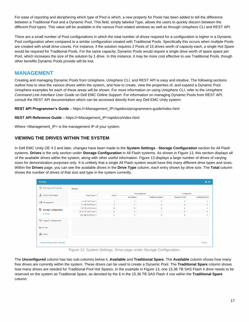
In Dell EMC Unity OE 4.2 and later, changes have been made to the System Settings - Storage Configuration section for All Flash
systems. Drives is the only section under Storage Configuration in All Flash systems. As shown in Figure 13, this section displays all
of the available drives within the system, along with other useful information. Figure 13 displays a large number of drives of varying
sizes for demonstration purposes only. It is unlikely that a single All Flash system would have this many different drive types and sizes.
Within the Drives page, you can see the available drives in the Drive Type column, each entry shown by drive size. The Total column
shows the number of drives of that size and type in the system currently.
Figure 13. System Settings. Drive page under Storage Configuration.
The Unconfigured column has two sub-columns below it, Available and Traditional Spare. The Available column shows how many
free drives are currently within the system. These drives can be used to create a Dynamic Pool. The Traditional Spare column shows
how many drives are needed for Traditional Pool Hot Spares. In the example in Figure 13, one 15.36 TB SAS Flash 4 drive needs to be
reserved on the system as Traditional Spare, as denoted by the 1 in the 15.36 TB SAS Flash 4 row within the Traditional Spare
column.

18
The Configured column is also subdivided into two sub-columns, Dynamic Pool and Traditional Pool. These sub-columns show how
many drives are currently configured within Dynamic Pools and Traditional Pools. In this example, a number of 15.36 TB SAS Flash 4
drives have been placed into a Traditional Pool, and no other Pools or drives have been configured on the system.
For each non-zero number listed under the Unconfigured column, a clickable link is present. As shown in Figure 14, when the link for
the 74 unconfigured 7.68 TB SAS Flash 4 drives are selected in the Unconfigured column, a drive list is displayed. This list shows the
drive locations for the free drives within the system, along with other information. This table can be used to easily determine the
locations of the free drives within the system.
Figure 14. System Settings. Drive page under Storage Configuration. Hyperlink selected.
CREATING A DYNAMIC POOL
In Dell EMC Unity OE version 4.2 and later, a Dynamic Pool is the only Pool type that can be created in Unisphere. To create a
Traditional Pool, you must use Unisphere CLI or REST API. From the Pools page in Unisphere, select the symbol to Launch the
Create Pool Wizard to create a Dynamic Pool. Figure 15 below shows the Name and Description step within the Create Pool wizard.
On this page you can provide a name for the Pool and a short description to provide additional information about the Pool, such as what
the Pool should be used for.
Figure 15. Create Pool Wizard. Name and Description step.
The next step within the Create Pool wizard is the Tiers step. In this step the Tier to create is selected, based on Drive Type available,
and the RAID type for the tier can also be customized. As shown in Figure 16, Extreme Performance Tier is the only available choice
19
as this is an All Flash system. Once Extreme Performance Tier is selected, you may choose the RAID protection for the Pool. RAID 5 is
the default selection when creating a Pool.
Figure 16. Create Pool Wizard. Tiers step.
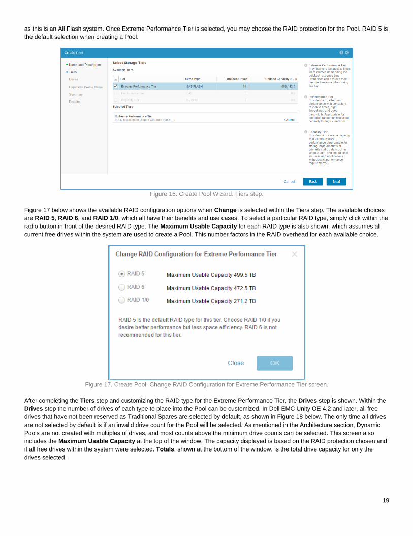
Figure 17 below shows the available RAID configuration options when Change is selected within the Tiers step. The available choices
are RAID 5, RAID 6, and RAID 1/0, which all have their benefits and use cases. To select a particular RAID type, simply click within the
radio button in front of the desired RAID type. The Maximum Usable Capacity for each RAID type is also shown, which assumes all
current free drives within the system are used to create a Pool. This number factors in the RAID overhead for each available choice.
Figure 17. Create Pool. Change RAID Configuration for Extreme Performance Tier screen.
After completing the Tiers step and customizing the RAID type for the Extreme Performance Tier, the Drives step is shown. Within the
Drives step the number of drives of each type to place into the Pool can be customized. In Dell EMC Unity OE 4.2 and later, all free
drives that have not been reserved as Traditional Spares are selected by default, as shown in Figure 18 below. The only time all drives
are not selected by default is if an invalid drive count for the Pool will be selected. As mentioned in the Architecture section, Dynamic
Pools are not created with multiples of drives, and most counts above the minimum drive counts can be selected. This screen also
includes the Maximum Usable Capacity at the top of the window. The capacity displayed is based on the RAID protection chosen and
if all free drives within the system were selected. Totals, shown at the bottom of the window, is the total drive capacity for only the
drives selected.

20
Figure 18. Create Pool Wizard. Drives step.
Also shown in this example is an informational message stating that the capacity for some of the drives selected will not be fully used at
this time. This is done to warn the user that not all space from all drives selected will be usable at this time. This occurs when the
number of drives for a particular drive size is not at least the stripe width plus 1 additional drive. In Figure 18 above, there are only 1 -
1.6 TB and 1 – 3.2 TB SAS Flash 4 drives available, which is why the message is displayed. This topic is covered in more detail in the
Supported Drives portion of the Supported Configurations section of this paper.
The Drives step also provides information when the minimum number of drives selected does not match or exceed the minimum
required for the RAID type selected. In the example below, Figure 19, the minimum drive count of 6 for RAID 5 has not been met.
Currently only 2 – 7.6 TB SAS Flash 4 drives have been selected. As different size drives can be mixed, the warning displayed shows
that at least 4 more of the same drive type listed must be selected.
Figure 19. Create Pool Wizard. Drives step. Minimum drive count not selected.
As outlined in the Drive Partnership Groups portion of the Architecture section, there are a few drive counts that cannot be selected
when creating or expanding a Dynamic Pool. This occurs when the minimum number of drives to start the next drive partnership group
has not been met. As shown in Figure 20, when the number of drives selected is invalid due to the drive partnership group criteria not
being met, a warning is displayed. This warning outlines the options available, either the drive count can be reduced or increased by
some number of drives.

21
Figure 20. Create Pool Wizard. Drives step. Invalid drive count selected.
Figure 21 below shows an example when only the 7.6 TB SAS Flash drives are selected. When the number of drives meets the
minimum drive counts required, and all space can be utilized, no warning are displayed. As mentioned previously, a typical All Flash
configuration would most likely not include this many different drive sizes and types.
Figure 21. Create Pool Wizard. Drives step. Desired drive count selected.
The next step within the Create Pool wizard is the Capability Profile Name step. If the Dynamic Pool will be used for VMware VVol
storage, a VMware Capability Profile must be created for the Pool. If desired, selected the checkbox in front of the Create VMware
Capability Profile for the Pool option and provide a Name and an optional Description. In this example, we will not create a
Capability Profile.

22
Figure 22. Create Pool Wizard. Capability Profile Name step.
The last step within the Create Pool wizard is the Summary step. This step summarizes the choices made within the previous steps.
As shown in Figure 23 below, the Name, Description, Tier, RAID Configuration, Drive Type, Drives, and Usable Capacity based on
the previous selections are shown. If any of the information needs to be changed, Back can be selected to correct a choice. Otherwise
select Finish to create the Dynamic Pool.
Figure 23. Create Pool Wizard. Summary step.
The last page within the Create Pool wizard is the Results page. Once the Pool creation occurs, a background task is started and this
wizard can be closed. In this window, the Overall Status of the background task is displayed, as well as Details for each step in the
process. Figure 24 below shows an example of the Results page when the Pool creation is allowed to complete.

23
Figure 24. Create Pool Wizard. Results step.
VIEWING THE PROPERTIES OF A DYNAMIC POOL
To view the Pools created on the system, select Pools under the Storage header in the left pane of Unisphere. On this page, the Pools
are shown along with other information. New in Dell EMC Unity OE version 4.2 and later is the Type column. This column can be added
to the view by selecting the Customize your view button, denoted by the icon, and selecting the Type checkbox under Columns.
Figure 25 below shows a system with multiple Pools created on it. In this example we can easily determine which Pool is a Traditional
Pool and which one is a Dynamic Pool by reviewing the Type column. The Type can also be seen in the quick properties view to the
right after a Pool is selected. To view the properties of a Pool, select the View/Edit button, denoted by the icon, or double-click the
Pool name.
Figure 25. Unisphere - Pools page.
The Pool Properties window on All Flash storage systems contains 5 tabs, General, Drives, Usage, Snapshot Settings, and RAID.
The General tab is shown by default when opening the Pool properties window. Within the window is basic information about the Pool,
such as its Name, Description, Size, and Type. An example of this screen is shown below in Figure 26.

24
Figure 26. Dynamic Pool properties window. General tab.
The second tab within the Pool Properties window is the Drives tab. This tab displays all drives currently in use by the Pool. This tab
has a number of default columns which include Name, Type, Capacity (GB), Details (K RPM), and Estimate EOL. These columns
can be further sorted or filtered as needed. Figure 27 shows an example of this screen.
Figure 27. Dynamic Pool properties window. Drives tab.
The next tab within the Pool Properties window is the Usage tab. This tab includes subcategories such as Capacity, which includes
capacity information about the Pool, and Storage Resources, which lists what is currently created on the Pool. As shown in Figure 28,
the Capacity section includes a large amount of information about the Pool. The Used, Free, and Non-base Space capacities are all
shown, along with the Subscribed Percentage of the Pool. Below the chart is the Alert Threshold, which is customizable and allows
the user to have the system flag an alert when the storage allocation surpasses the percentage set. The Compression Savings can
also be seen on this screen for Dell EMC Unity OE codes prior to the 4.3 release, which includes the GBs, Percentage, and Ratio
savings values. In OE 4.3, Compression Savings has been replaced with Data Reduction Savings. Lastly, a chart on the Pool usage is
present, though not shown in the example as no resources have been created on this Pool.
25
Figure 28. Dynamic Pool properties window. Usage tab.
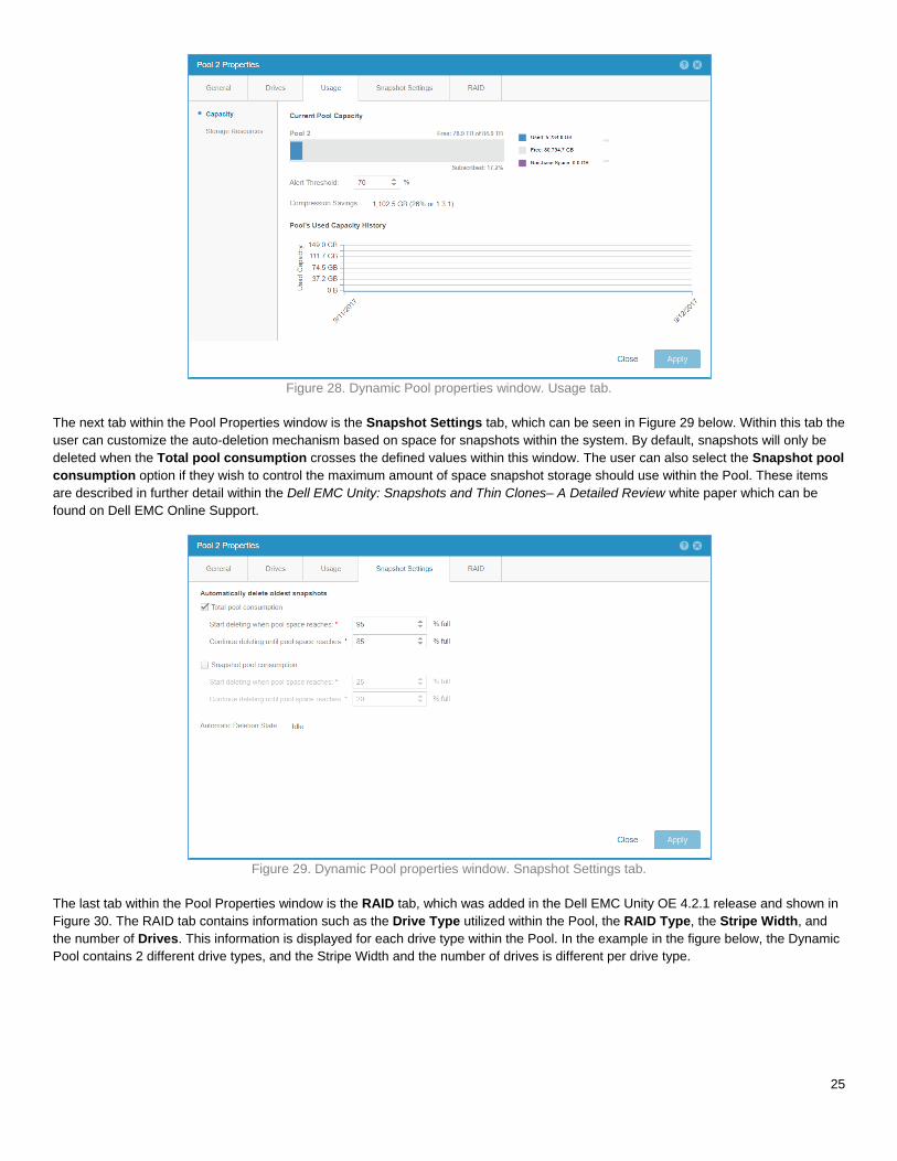
The next tab within the Pool Properties window is the Snapshot Settings tab, which can be seen in Figure 29 below. Within this tab the
user can customize the auto-deletion mechanism based on space for snapshots within the system. By default, snapshots will only be
deleted when the Total pool consumption crosses the defined values within this window. The user can also select the Snapshot pool
consumption option if they wish to control the maximum amount of space snapshot storage should use within the Pool. These items
are described in further detail within the Dell EMC Unity: Snapshots and Thin Clones– A Detailed Review white paper which can be
found on Dell EMC Online Support.
Figure 29. Dynamic Pool properties window. Snapshot Settings tab.
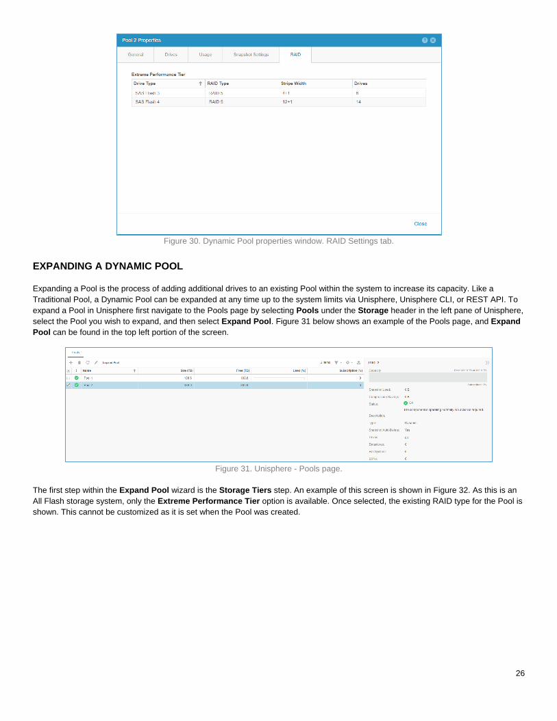
The last tab within the Pool Properties window is the RAID tab, which was added in the Dell EMC Unity OE 4.2.1 release and shown in
Figure 30. The RAID tab contains information such as the Drive Type utilized within the Pool, the RAID Type, the Stripe Width, and
the number of Drives. This information is displayed for each drive type within the Pool. In the example in the figure below, the Dynamic
Pool contains 2 different drive types, and the Stripe Width and the number of drives is different per drive type.
26
Figure 30. Dynamic Pool properties window. RAID Settings tab.
EXPANDING A DYNAMIC POOL
Expanding a Pool is the process of adding additional drives to an existing Pool within the system to increase its capacity. Like a
Traditional Pool, a Dynamic Pool can be expanded at any time up to the system limits via Unisphere, Unisphere CLI, or REST API. To
expand a Pool in Unisphere first navigate to the Pools page by selecting Pools under the Storage header in the left pane of Unisphere,
select the Pool you wish to expand, and then select Expand Pool. Figure 31 below shows an example of the Pools page, and Expand
Pool can be found in the top left portion of the screen.
Figure 31. Unisphere - Pools page.
The first step within the Expand Pool wizard is the Storage Tiers step. An example of this screen is shown in Figure 32. As this is an
All Flash storage system, only the Extreme Performance Tier option is available. Once selected, the existing RAID type for the Pool is
shown. This cannot be customized as it is set when the Pool was created.
27
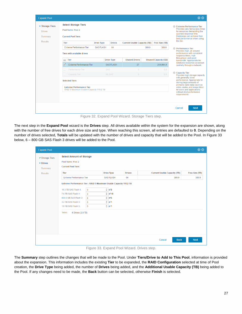
Figure 32. Expand Pool Wizard. Storage Tiers step.
The next step in the Expand Pool wizard is the Drives step. All drives available within the system for the expansion are shown, along
with the number of free drives for each drive size and type. When reaching this screen, all entries are defaulted to 0. Depending on the
number of drives selected, Totals will be updated with the number of drives and capacity that will be added to the Pool. In Figure 33
below, 6 – 800 GB SAS Flash 3 drives will be added to the Pool.
Figure 33. Expand Pool Wizard. Drives step.
The Summary step outlines the changes that will be made to the Pool. Under Tiers/Drive to Add to This Pool, information is provided
about the expansion. This information includes the existing Tier to be expanded, the RAID Configuration selected at time of Pool
creation, the Drive Type being added, the number of Drives being added, and the Additional Usable Capacity (TB) being added to
the Pool. If any changes need to be made, the Back button can be selected, otherwise Finish is selected.

28
Figure 34. Expand Pool Wizard. Summary step.
The last step within the Expand Pool wizard is the Results step. Once the expansion is started, a background Job is started and the
wizard can be closed. Not until the Job completes will the space be available within the Pool. The length the expansion process takes
directly depends on the number of drives being added to the system. In Figure 35 below, the expansion process was allowed to finish
before the window was closed.
Figure 35. Expand Pool Wizard. Results step.

29
INTEROPERABILITY
Dynamic Pools, like Traditional Pools, are fully supported with all storage resource types and software features within the system. While
Dynamic Pools support all storage resource types and software features, other features of the storage system needed to be updated to
support Dynamic Pools. The following sections outline a number of changes made to certain software features to support Dynamic
Pools.
DATA AT REST ENCRYPTION
Data at Rest Encryption is fully supported on systems utilizing Traditional and Dynamic Pools. With Dynamic Pools however, changes
to the D@RE algorithm were needed for D@RE to be supported. With Traditional Pools, encryption keys are created and allocated on
a per drive basis within the Traditional Pool private RAID groups. This allocation of encryption keys occurs whenever a Pool is created,
or drives are added to the Traditional Pool. Knowing that the drive configuration is static, this model for allocating keys is complete.
With Dynamic Pools, multiple private RAID groups can span the same drives within a drive partnership group, which makes the
Traditional Pool method of allocating keys not feasible. The key allocation algorithm has been updated to work with the tracking of the
drive extents within each drive partnership group. The drive extent algorithm tracks which drives are used within the Pool, and with this
information, D@RE keys can be allocated to each individual drive. As drives are allocated to the Pool, new keys can also be supplied.
D@RE continues to be enabled at the time the storage system is initialized, and no further steps are needed for Dynamic Pools. For
more information on Data at Rest Encryption, please review the white paper titled Dell EMC Unity: Data at Rest Encryption – A Detailed
Review on Dell EMC Online Support.
IMPORT
In Dell EMC Unity OE version 4.1, Dell EMC Unity Native SAN Copy Import and File Import were introduced. These features provide an
automated method for migrating Block storage resources, such as LUNs and Consistency Groups, and NFSv3 File Systems mounted
on a Virtual Data Mover (VDM) from a VNX1/VNX2 storage system to a Dell EMC Unity system. In Dell EMC Unity OE version 4.2,
support for CIFS based File Systems mounted on a VDM was also introduced. Import has been updated to include support for Dynamic
Pools. When selecting the target Pool for the import session, both Traditional and Dynamic Pools will be available. To further
distinguish the different Pools on the system, a Type field has been added to the Pool selection window to easily differentiate which
Pool is which type. For more information on Import, please review the white paper titled Dell EMC Unity: Migration Technologies – A
Detailed Review on Dell EMC Online Support.
LOCAL LUN MOVE
In Dell EMC Unity OE version 4.1, Local LUN Move was introduced. Local LUN Move is a native feature within the storage system used
to easily move LUNs and VMFS Datastores within the same Pool or between Pools within the same system. The Local LUN Move
related windows have been updated to include support for Dynamic Pools, as the source or destination of the Move session. When
selecting the destination Pool by name, a Type field has also been added to the window to easily report what type of Pool, either
Traditional or Dynamic, the selected Pool is. Local LUN Move can not only be used for manual load balancing between Pools, but also
for migrating resources from a Traditional Pool to a Dynamic Pool. For more information on Local LUN Move, please review the white
paper titled Dell EMC Unity: Migration Technologies – A Detailed Review on Dell EMC Online Support.
REPLICATION
Dell EMC Unity native Synchronous and Asynchronous Replication is fully supported with Traditional and Dynamic Pools. When
configuring local or remote replication, the source or destination Pool can be either type of Pool, either Traditional or Dynamic. This
flexibility in configuration options allows systems which do not support Dynamic Pools, such as Dell EMC UnityVSA, a Dell EMC Unity
Hybrid system, or another All Flash system which is not running Dell EMC Unity OE version 4.2 or later to replicate to or from a
Dynamic Pool. When configuring replication, a Type field has been added to easily determine the type of Pool that was selected as the
destination. This Type field is only present on systems running Dell EMC Unity OE version 4.2 or later. For more information on
Replication, please review the white paper titled Dell EMC Unity: Replication Technologies – A Detailed Review on Dell EMC Online
Support.

30
CONCLUSION
In Dell EMC Unity OE version 4.2, Dynamic Pool technology is introduced for Dell EMC Unity All Flash storage systems, and is the new
default Pool type when creating Pools in Unisphere. This new Pool technology is designed from the ground up, with a new method for
allocating space within the Pool than Traditional Pools. The new design allows for flexible deployment options, and allows users to
design or expand Dynamic Pools with a specific capacity in mind. The Pool sizing requirements are based on minimum drive counts,
and not drive multiples. As long as the minimum drive counts are met, the Pool can be any number of drives, and can also be expanded
by a single drive in most circumstances to increase the capacity of the Pool.
With Dynamic Pools, no Hot Spares for failed drive replacement are required, as all space for drive rebuilds is allocated within the Pool.
Drives which would be reserved as Hot Spares for Traditional Pools are incorporated into the Pool to further spread out user space and
space to use for drive rebuilds. As drives within Dynamic Pools are partitioned into extents, the Pool can easily move data around to
balance workloads when the Pool is expanded. If a drive were to fail, multiple extents can be rebuilt at the same time, and to multiple
drives within the Pool. This further reduces the amount of time a rebuild of a drive takes when compared to a rebuild within a Traditional
Pool.
Dynamic Pools are also designed to help mitigate flash wear. As drives previously reserved as Hot Spares are now incorporated into
the Pool, the user data and workloads are spread out across more drives. This reduces the amount of wear per drive within the Pool.
Also, wear is further monitored within a Dynamic Pool, and if needed, data can be moved between drive partnership groups to further
spread out wear. This is an automated process that requires no intervention by the user.
REFERENCES
White Papers
Dell EMC Unity: Unisphere Overview
Dell EMC Unity: Introduction to the Platform
Dell EMC Unity: Snapshots and Thin Clones
Dell EMC Unity: Replication Technologies
Dell EMC UnityVSA
Dell EMC Unity: Data at Rest Encryption
Dell EMC Unity: FAST Technology Overview
Dell EMC Unity: Migration Technologies
Other References
Dell EMC Online Support
Dell EMC Unity InfoHub (http://bit.ly/unityinfohub)
Unisphere Command Line Interface User Guide