
Dell EMC PowerStore Planning Guide · Height 8.64 cm (3.4 in) Width 44.45 cm (17.5 in) Depth 34.29...
26
Dell EMC PowerStore Planning Guide
Transcript of Dell EMC PowerStore Planning Guide · Height 8.64 cm (3.4 in) Width 44.45 cm (17.5 in) Depth 34.29...
Dell EMC PowerStorePlanning Guide
Notes, cautions, and warnings
NOTE: A NOTE indicates important information that helps you make better use of your product.
CAUTION: A CAUTION indicates either potential damage to hardware or loss of data and tells you how to avoid the
problem.
WARNING: A WARNING indicates a potential for property damage, personal injury, or death.
© 2020 Dell Inc. or its subsidiaries. All rights reserved. Dell, EMC, and other trademarks are trademarks of Dell Inc. or itssubsidiaries. Other trademarks may be trademarks of their respective owners.
May 2020
Rev. A00
Additional Resources.......................................................................................................................4
1 Introduction................................................................................................................................. 5Introduction to PowerStore ................................................................................................................................................ 5
Appliances.........................................................................................................................................................................5Clusters............................................................................................................................................................................. 5
Planning and installation overview.......................................................................................................................................6
2 Site planning................................................................................................................................7Rack space guidelines............................................................................................................................................................7Technical specifications........................................................................................................................................................ 7
Dimensions and weight....................................................................................................................................................7Power requirements........................................................................................................................................................ 8Shipping and storage requirements...............................................................................................................................9
3 Licensing and Workstation Requirements...................................................................................... 11PowerStore Licensing.......................................................................................................................................................... 11VMware vSphere Licensing (Applies to PowerStore X model appliances)................................................................... 11Workstation requirements...................................................................................................................................................12
PowerStore Discovery Utility........................................................................................................................................12
4 SupportAssist.............................................................................................................................13Operational description of SupportAssist™....................................................................................................................... 13SupportAssist options..........................................................................................................................................................14SupportAssist Gateway Connect options......................................................................................................................... 15
Requirements for SupportAssist Gateway Connect..................................................................................................15SupportAssist Direct Connect options.............................................................................................................................. 15
Requirements for SupportAssist Direct Connect.......................................................................................................16Configuring SupportAssist.................................................................................................................................................. 16
A Discovering PowerStore Appliances............................................................................................. 17Discover your system...........................................................................................................................................................17
Discovery with a direct connection.............................................................................................................................. 17Discovery with remote connection.............................................................................................................................. 18
B Port Usage.................................................................................................................................19Appliance network ports..................................................................................................................................................... 19Appliance network ports related to file.............................................................................................................................20Network ports related to PowerStore X model appliances........................................................................................... 23
C Rack Space Planning Worksheets................................................................................................25Sample worksheet for rack space planning..................................................................................................................... 25Blank worksheet for rack space planning.........................................................................................................................26
Contents
Contents 3
Additional ResourcesAs part of an improvement effort, revisions of the software and hardware are periodically released. Some functions that are described inthis document are not supported by all versions of the software or hardware currently in use. The product release notes provide the mostup-to-date information about product features. Contact your technical support professional if a product does not function properly ordoes not function as described in this document.
Where to get helpSupport, product, and licensing information can be obtained as follows:
• Product information
For product and feature documentation or release notes, go to the PowerStore Documentation page at www.dell.com/powerstoredocs.
• Troubleshooting
For information about products, software updates, licensing, and service, go to www.dell.com/support and locate the appropriateproduct support page.
• Technical support
For technical support and service requests, go to www.dell.com/support and locate the Service Requests page. To open a servicerequest, you must have a valid support agreement. Contact your Sales Representative for details about obtaining a valid supportagreement or to answer any questions about your account.
Preface
4 Additional Resources
IntroductionUse this document to better understand the installation process and prepare your site and workstation for a successful PowerStoreimplementation. This chapter includes the following topics:
Topics:
• Introduction to PowerStore• Planning and installation overview
Introduction to PowerStorePowerStore achieves new levels of operational simplicity and agility, utilizing a container-based microservices architecture, advancedstorage technologies, and built-in machine learning to unlock the power of your data. PowerStore is a versatile platform with aperformance-centric design that delivers multi-dimensional scale, always on data reduction, and support for next generation media. Itbrings the simplicity of public cloud to on-premises infrastructure, streamlining operations with a built-in machine learning engine andseamless automation, while offering predictive analytics to easily monitor, analyze, and troubleshoot the environment. PowerStore is alsohighly adaptable, providing the flexibility to host specialized workloads directly on the appliance and modernize infrastructure withoutdisruption, all while offering investment protection through flexible payment solutions and data-in-place upgrades.
PowerStore appliances are available in one of the following deployment models:
• PowerStore T model appliances (1000T, 3000T, 5000T, 7000T, and 9000T) are storage-centric, and enable you to manage andprovision block and file storage to external hosts. During initial configuration, you can choose to configure an appliance for unified(block and file) or block-only storage.
• PowerStore X model appliances (1000X, 3000X, 5000X, 7000X, and 9000X) are application and storage-centric, and provide ahypervisor layer in addition to block storage. This additional capability enables you to deploy and manage virtual machines andapplications.
AppliancesA PowerStore appliance is a preconfigured infrastructure component that has both storage and compute resources. An appliance typicallyconsists of:
• A base enclosure – Holds up to 25 drives (minimum of six drives) and includes two nodes for high availability with data protection thatis implemented across the nodes.
• An expansion enclosure – Enables you to add more drives and increase the storage capacity for the appliance.
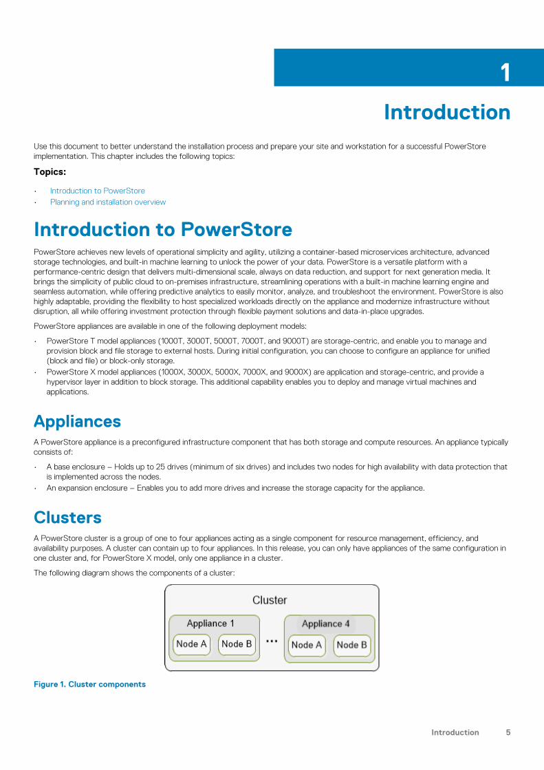
ClustersA PowerStore cluster is a group of one to four appliances acting as a single component for resource management, efficiency, andavailability purposes. A cluster can contain up to four appliances. In this release, you can only have appliances of the same configuration inone cluster and, for PowerStore X model, only one appliance in a cluster.
The following diagram shows the components of a cluster:
Figure 1. Cluster components
1
Introduction 5

A cluster provides the following benefits:
• Reduced management complexity.• Enhanced performance and resource efficiency. Compute and storage resources are pooled within a cluster and the resources usage is
balanced across all of the cluster's appliances. Resources are re-balanced as needed to maintain and optimize the cluster'sperformance and resource usage. This is done based on the storage space usage trends and system performance evaluationsoccurring in the backend.
• Scalability. Start with a small configuration and easily add capacity or performance to the system by adding more appliances later tomeet business demand.
Planning and installation overviewThis section provides a high-level map of the steps you should plan on taking from planning through installation, and finally logging on tothe PowerStore Manager user interface. Ensure that you see the associated documentation resources for detailed instructions andrecommendations. You can access the documentation resources on the PowerStore Documentation page at www.dell.com/powerstoredocs.
Before the appliance arrives:1. Work with your infrastructure administrators to:
a. Configure your network and Top-of-Rack (TOR) switches based on the recommendations that are provided in the PowerStoreNetwork Planning Guide.
b. Obtain network-related information that you require for initial configuration of your cluster. Use the PowerStore InitialConfiguration Worksheet to plan and collect this information.
c. Configure the network ports to allow the cluster to communicate with pertinent hosts and applications securely and efficiently.See Port Usage for more information.
2. PowerStore requires a data center or server room that is equipped with controlled electrical, environmental, cabling, and safetysystems. Plan the site where you will install the appliances and the location of the appliance components (base enclosures andexpansion enclosures) in a rack. See Site planning for more information.
3. Set up a workstation that you will use to discover the appliances and configure the cluster. You may also need to download aDiscovery Utility from the support website and install it on this workstation. See Workstation requirements for more information.
Once the appliance arrives:See the PowerStore Quick Start Guide in the box to:
1. Unbox and install your appliance (base enclosure and expansion enclosures).2. Connect the enclosures to the network, and power up.3. Start the initial configuration process. For more information, see Discovering PowerStore Appliances4. Follow the initial configuration prompts by specifying information that you collected in the PowerStore Initial Configuration Worksheet.
The PowerStore Installation and Service Guide also includes installation instructions for later reference.
NOTE: Either during the initial configuration process or once you log on to PowerStore Manager, it is strongly
recommended that you enable the SupportAssist feature to accelerate problem diagnosis, perform troubleshooting, and
help speed time to resolution. For more information, see SupportAssist.
Once you have completed initial configuration:1. Log in to PowerStore Manager using the administrator credentials you set up during initial configuration.2. Configure settings for your cluster and start provisioning PowerStore Manageruser accounts, storage resources, and policies. See the
PowerStore Setting Up PowerStore Manager Guide for more information about the recommended steps when you log in to thePowerStore Manager for the first time.
6 Introduction
Site planning
This chapter contains the following topics:
Topics:
• Rack space guidelines• Technical specifications
Rack space guidelinesConsider the following rack space guidelines when planning the location of the appliance components:
• Leave 2U at the bottom of the rack for serviceability and power cable management.• Stack base enclosure with no expansion enclosures from the bottom, starting at the 3U mark.• Stack base enclosure in order from least attached expansion enclosures to most, then from least drives to most drives.• Stack the expansion enclosure attached to the first base enclosure directly above the base enclosure.• Subsequent base enclosures are stacked in alternating, flipped order.
See Rack Space Planning Worksheets to view a sample rack space plan and then use the blank worksheet to plan for the appliances inyour cluster.
Technical specificationsReview the technical specifications to plan and prepare the site where you are installing the PowerStore cluster.
Dimensions and weight
Base enclosureTable 1. 2U, 25-drive base enclosure dimensions and weight
Dimension Value
Weight (fully populated) 41.7 kg (92 lbs)
Vertical size 2 NEMA units
Height 8.64 cm (3.4 in)
Width 44.45 cm (17.5 in)
Depth 79.5 cm (31.3 in)
NOTE: The weight does not include mounting rails. Allow 3.6 kg (8 lbs) for a rail set.
2U, 25-drive expansion enclosureTable 2. 2U, 25-drive expansion enclosure dimensions and weight
Dimension Value
Weight (fully populated) 34.98 kg (77.11 lb)
Vertical size 2 NEMA units
2
Site planning 7

Dimension Value
Height 8.64 cm (3.4 in)
Width 44.45 cm (17.5 in)
Depth 34.29 cm (13.5 in)
NOTE: The weight does not include mounting rails. Allow 3.6 kg (8 lbs) for a rail set.
Power requirementsPower requirements will vary depending on system configuration, loading, and environmental conditions. The table below provides worstcase data. To estimate power consumption values for your specific environment, go to https://powercalculator.emc.com/.
Table 3. Power requirements
Requirement 1000T/ 1000X 3000T/3000X 5000T 5000X 7000T/7000X 9000T/9000X
Maximum inputpower
240 VAC ± 10%, single phase
AC Line Current(operatingmaximum at 200VAC)
8.1 A 8.1 A 9.0 A 9.0 A 9.3 A 10.4 A
PowerConsumption(operatingmaximum at 200VAC)
1629.6 VA (1597W)
1629.6 VA (1597W)
1792.9 VA (1757W)
1792.9 VA (1757W)
1868.4 VA (1831W)
2088.8 VA (2047W)
Heat Dissipation(operatingmaximum)
5.74 x 10⁶ J/hr,(5,449 Btu/hr)
5.74 x 10⁶ J/hr,(5,449 Btu/hr)
6.32 x 10⁶ J/hr,(5,995 Btu/hr)
6.32 x 10⁶ J/hr,(5,995 Btu/hr)
6.59 x 10⁶ J/hr,(6,248 Btu/hr)
7.37 x 10⁶ J/hr,(6,985 Btu/hr)
AC Inlet type IEC320-C14 or IEC320-C20 appliance coupler per powerzone
IEC320-C20 appliance coupler per power zone
Normal inputfrequency
47 Hz–63 Hz
Maximum inrushcurrent
45 Apk "cold" per line cord at any line voltage
AC protection 20 A fuse on each power supply, single line
Ride-throughtime
10 ms min
Current sharing ± 5 percent of full load, between power supplies
Startup SurgeCurrent
120 Apk "hot" per line cord, at any line voltage
Table 4. High ambient temperature shutdown
Ambient temperature Hardware fault Consequence
Above 45° C (113° F) None Non-critical warning generated .
Above 50° C (122° F) None Critical alert generated. System shutsdown after five minute timer expires.If the temperature returns to lessthan 45° C (113° F) , the systempowers on..
Any Three hottest drives have average temperature of 50° C(122° F)
System shuts down after five minutetimer expires.
8 Site planning
Ambient temperature Hardware fault Consequence
Any Two fans fault System shuts down after five minutetimer expires.
Shipping and storage requirementsNOTE: Systems and components must not experience changes in temperature and humidity that are likely to cause
condensation to form on or in that system or component. Do not exceed the shipping and storage temperature gradient
of 45°F/hr (25°C/hr).
Table 5. Shipping and storage requirements
Requirement Description
Ambient temperature -40° F to 149°F (-40°C to 65°C)
Temperature gradient 45°F/hr (25°C/hr)
Relative humidity 10% to 90% noncondensing
Elevation -50 to 35,000 ft (-16 to 10,600 m)
Storage time (unpowered) Recommendation Do not exceed 6 consecutive months ofunpowered storage.
Base enclosure airflowThe base enclosure uses an adaptive cooling algorithm that increases or decreases fan speed as the unit senses changes to the externalambient temperature. Exhaust increases with ambient temperature and fan speed, and is roughly linear within recommended operatingparameters. Note that the information in the table below is typical, and was measured without cabinet front/rear doors that wouldpotentially reduce front-to-back air flow.
Table 6. Base enclosure airflow
Max Airflow CFM Min Airflow CFM Max Power Usage(Watts)
165 CFM 50 CFM 850 W
Environmental recoveryIf the system exceeds the maximum ambient temperature by approximately 10°C (18°F), the nodes in the system begin an orderlyshutdown that saves cached data, and then shut themselves down. Link control cards (LCCs) in each expansion enclosure in the systempower down drives but remain powered on.
If the system detects that the temperature has dropped to an acceptable level, it restores power to the base enclosures and the LCCsrestore power to their drives.
Air quality requirementsThe products are designed to be consistent with the requirements of the American Society of Heating, Refrigeration and Air ConditioningEngineers (ASHRAE) Environmental Standard Handbook and the most current revision of Thermal Guidelines for Data ProcessingEnvironments, Second Edition, ASHRAE 2009b.
Cabinets are best suited for Class 1 datacom environments, which consist of tightly controlled environmental parameters, includingtemperature, dew point, relative humidity and air quality. These facilities house mission-critical equipment and are typically fault-tolerant,including the air conditioners.
The data center should maintain a cleanliness level as identified in ISO 14664-1, class 8 for particulate dust and pollution control. The airentering the data center should be filtered with a MERV 11 filter or better. The air within the data center should be continuously filteredwith a MERV 8 or better filtration system. In addition, efforts should be maintained to prevent conductive particles, such as zinc whiskers,from entering the facility.
The allowable relative humidity level is 20 to 80% non condensing, however, the recommended operating environment range is 40 to 55%.For data centers with gaseous contamination, such as high sulfur content, lower temperatures and humidity are recommended to minimizethe risk of hardware corrosion and degradation. In general, the humidity fluctuations within the data center should be minimized. It is also
Site planning 9
recommended that the data center be positively pressured and have air curtains on entry ways to prevent outside air contaminants andhumidity from entering the facility.
For facilities below 40% relative humidity, it is recommended to use grounding straps when contacting the equipment to avoid the risk ofElectrostatic discharge (ESD), which can harm electronic equipment.
As part of an ongoing monitoring process for the corrosiveness of the environment, it is recommended to place copper and silver coupons(per ISA 71.04-1985, Section 6.1 Reactivity), in airstreams representative of those in the data center. The monthly reactivity rate of thecoupons should be less than 300 Angstroms. When monitored reactivity rate is exceeded, the coupon should be analyzed for materialspecies and a corrective mitigation process put in place.
Storage time (unpowered) recommendation: do not exceed 6 consecutive months of unpowered storage.
Fire suppressant disclaimerFire prevention equipment in the computer room should always be installed as an added safety measure. A fire suppression system is theresponsibility of the customer. When selecting appropriate fire suppression equipment and agents for the data center, choose carefully. Aninsurance underwriter, local fire marshal, and local building inspector are all parties that you should consult during the selection of a firesuppression system that provides the correct level of coverage and protection.
Equipment is designed and manufactured to internal and external standards that require certain environments for reliable operation. We donot make compatibility claims of any kind nor do we provide recommendations on fire suppression systems. It is not recommended toposition storage equipment directly in the path of high pressure gas discharge streams or loud fire sirens so as to minimize the forces andvibration adverse to system integrity.
NOTE: The previous information is provided on an “as is” basis and provides no representations, warranties, guarantees
or obligations on the part of our company. This information does not modify the scope of any warranty set forth in the
terms and conditions of the basic purchasing agreement between the customer and the manufacturer.
Shock and vibrationProducts have been tested to withstand the shock and random vibration levels. The levels apply to all three axes and should be measuredwith an accelerometer on the equipment enclosures within the cabinet and shall not exceed:
Platform condition Response measurement level
Non operational shock 10 G’s, 7 ms duration
Operational shock 3 G’s, 11 ms duration
Non operational random vibration 0.40 Grms, 5–500 Hz, 30 minutes
Operational random vibration 0.21 Grms, 5–500 Hz, 10 minutes
Systems that are mounted on an approved package have completed transportation testing to withstand the following shock andvibrations in the vertical direction only and shall not exceed:
Packaged system condition Response measurement level
Transportation shock 10 G’s, 12ms duration
Transportation random vibration • 1.15 Grms• 1 hour Frequency range 1–200 Hz
10 Site planning
Licensing and Workstation Requirements
This chapter includes the following topics:
Topics:
• PowerStore Licensing• VMware vSphere Licensing (Applies to PowerStore X model appliances)• Workstation requirements
PowerStore LicensingPowerStore license is automatically obtained and installed on all the appliances in your cluster during initial configuration. It includes accessto all features available with PowerStore.
NOTE: PowerStore license does not include the VMware vSphere license. For PowerStore X model cluster licensing, you
must also obtain or use a separate VMware vSphere license. For more information, see VMware vSphere Licensing
(Applies to PowerStore X model appliances).
To obtain licenses automatically during and after initial configuration, ensure that the port 443 is open. The cluster communicates with theDell EMC licensing management system (ELMS) using port 443 to obtain the license file. If there is an issue obtaining the license file, yourcluster will operate in a 30-day trial period. The system will attempt to obtain a license automatically every 24 hours. To review the statusof your license, in PowerStore Manager, go to Settings > Licensing. An Active status indicates that all the appliances in the cluster havea valid license.
If you do not have an active license yet, you can click Refresh on the PowerStore Licensing page to try obtaining the licenseautomatically. Or, click Install License to manually install the license.
NOTE: You do not need a separate PowerStore license when installing PowerStore operating environment software and
firmware upgrades.
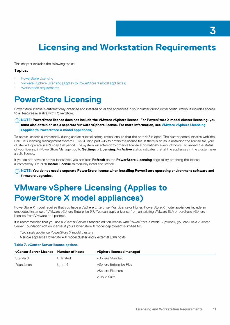
VMware vSphere Licensing (Applies toPowerStore X model appliances)PowerStore X model requires that you have a vSphere Enterprise Plus License or higher. PowerStore X model appliances include anembedded instance of VMware vSphere Enterprise 6.7. You can apply a license from an existing VMware ELA or purchase vSpherelicenses from VMware or a partner.
It is recommended that you use a vCenter Server Standard edition license with PowerStore X model. Optionally you can use a vCenterServer Foundation edition license, if your PowerStore X model deployment is limited to:
• Two single appliance PowerStore X model clusters• A single appliance PowerStore X model cluster and 2 external ESXi hosts
Table 7. vCenter Server license options
vCenter Server License Number of hosts vSphere licensed managed
Standard Unlimited vSphere Standard
vSphere Enterprise Plus
vSphere Platinum
vCloud Suite
Foundation Up to 4
3
Licensing and Workstation Requirements 11

Workstation requirementsOnce you complete the physical installation process, plan to have a Windows-based workstation or virtual machine for discovering theappliances and begin initial configuration. Ensure that the workstation or virtual machine meet the following requirements:
• Running Microsoft ® Windows ® 10 operating system.• Includes at least one Ethernet/RJ-45 network port.• Includes the latest version of one of the following Web browsers:
• Google Chrome• Mozilla Firefox• Microsoft Edge• Microsoft Internet Explorer 11• Apple Safari
PowerStore Discovery UtilityIf you do not have access to the base enclosure that you want to configure, you must download and run the PowerStore Discovery Utility.The PowerStore T model Discovery Utility enables you to find unconfigured PowerStore T model and PowerStore X model appliances onthe network, and initiate the initial configuration process to configure a cluster. Download this utility from the Dell support site atwww.dell.com/support.
For more information about the discovery requirements and process, see Discovering PowerStore Appliances.
12 Licensing and Workstation Requirements
SupportAssist
This chapter includes the following topics:
Topics:
• Operational description of SupportAssist• SupportAssist options• SupportAssist Gateway Connect options• SupportAssist Direct Connect options• Configuring SupportAssist
Operational description of SupportAssist™
The SupportAssist feature provides an IP-based connection that enables Dell EMC Support to receive error files and alerts from yourappliance, and to perform remote troubleshooting resulting in a fast and efficient time to resolution.
NOTE: It is strongly recommended that you enable the SupportAssist feature to accelerate problem diagnosis, perform
troubleshooting, and help speed time to resolution. If you do not enable the SupportAssist feature, you may need to
collect appliance information manually to assist Dell EMC Support with troubleshooting and resolving problems with
your appliance. Also, the SupportAssist feature must be enabled on the appliance for data to be sent to CloudIQ. For
information about CloudIQ, go to www.dell.com/support. After logging in, locate the CloudIQ Product Support page.
SupportAssist and securityThe SupportAssist feature employs multiple security layers throughout each step in the remote connectivity process to ensure that youand Dell EMC can use the solution with confidence:
• All notifications to Dell EMC originate from your site – never from an outside source – and are kept secure through the use ofAdvanced Encryption Standard (AES)-256 bit encryption.
• IP-based architecture integrates with your existing infrastructure and maintains the security of your environment.• Communications between your site and Dell EMC are bilaterally authenticated using RSA® digital certificates.• Only authorized Dell EMC Customer Service professionals verified through two-factor authentication can download the digital
certificates needed to view a notification from your site.• The optional SupportAssist v3 Policy Manager application enables you to grant or restrict Dell EMC Support access based on your own
unique guidelines and requirements, and includes a detailed audit log.
SupportAssist managementYou can manage the SupportAssist feature using the PowerStore Manager or the REST API. You can enable or disable the service andprovide the relevant information necessary for the SupportAssist option you select.
NOTE: The Gateway Connect with remote assist and Gateway Connect without remote assist options for centralized
SupportAssist do not support High Availability (HA). These options do not provide a failover capability to an active HA
SupportAssist Cluster. When a PowerStore appliance is deployed to a single HA gateway cluster server, which is the
only configuration option, there is no failover capability to the surviving gateway server in the cluster. If the HA gateway
server to which the appliance is connected goes down, the appliance will stop transferring any outbound files, such as a
call home and CloudIQ files, to Dell EMC Support. SupportAssist inbound connectivity for remote access to the
appliance will still function utilizing the surviving HA gateway server in the cluster. Also, the SupportAssist Gateway
Connect with remote assist and Gateway Connect without remote assist options should only be configured on the
designated primary appliance on your system.
4
SupportAssist 13

The appliance itself does not implement any policies. If you require more control over remote access to your appliance, you can use aPolicy Manager to set authorization permissions. The Policy Manager software component can be installed on a customer-supplied server.It controls remote access to your devices, maintains an audit log of remote connections, and supports file transfer operations. You cancontrol by whom, what, and when access to your appliance occurs. For more information about the Policy Manager, go to www.dell.com/support. After logging in, locate the applicable Support by Product page and search for the link to the specific SupportAssist producttechnical documentation.
SupportAssist communicationNOTE: SupportAssist cannot be enabled on PowerStore models configured with IPv6 for the management network.
SupportAssist is not supported over IPv6. Also, management network reconfiguration from IPv4 to IPv6 is not allowed
when SupportAssist is configured on a cluster.
Access to a DNS server is required for the SupportAssist feature to work.
The Connection Status of SupportAssist indicates both the state of the connection between PowerStore and the Dell EMC backendSupport services and the quality of service of the connection. The connection state is determined over five minute periods and the qualityof service of the connection is determined over 24 hour periods. The Connection Status of the connection can appear as one of thefollowing based on any of the appliances in the cluster:
• Unavailable – Connectivity data is unavailable. You may have lost contact with an appliance or SupportAssist has just beenenabled and there is insufficient data to determine the state.
• Disabled – SupportAssist has not been enabled.
• Not connected – Connectivity has been lost. Five consecutive keepalive failures have been detected.
• Reconnecting – PowerStore is attempting to reconnect after loss of connectivity. Five consecutive successful keepalive requestsare needed to transition back to a connected status.
The Connection Status of the connection can appear as one of the following based on the average of all the appliances in the clusterwhen PowerStore is connected to the Dell EMC backend Support services:
• Evaluating – The quality of service for the connection will be undetermined for the first 24 hours after SupportAssist is firstinitialized.
• Good – 80% or more of the consecutive keepalive requests were successful.
• Fair – Between 50% and 80% of the consecutive keepalive requests were successful.
• Poor – Less than 50% of the consecutive keepalive requests were successful.
SupportAssist optionsThe SupportAssist feature provides an IP-based connection that enables Dell EMC Support to receive error files and alerts from yoursystem, and to perform remote troubleshooting resulting in a fast and efficient time to resolution.
The SupportAssist options that are available by which to send appliance information to Dell EMC Support for remote troubleshooting are:
• Gateway Connect without remote access – For centralized SupportAssist and runs on a customer-supplied gateway server with two-way file transfer, which includes:
• Call-homes• CloudIQ support• Software notifications• Operating environment/firmware download from Dell EMC Support to the cluster
The SupportAssist gateway server is the single point of entry and exit for all IP-based SupportAssist activities for the appliancesassociated with the gateway.
• Gateway Connect with remote access – For centralized SupportAssist and runs on a customer-supplied gateway server with thesame two-way file transfer as Gateway Connect without remote access along with remote access for Dell EMC Support personnel.
• Direct Connect without remote access — For distributed SupportAssist that runs on individual appliances with the same two-way filetransfer as Gateway Connect without remote access.
• Direct Connect with remote access — For distributed SupportAssist that runs on individual appliances with the same two-way filetransfer as Gateway Connect without remote access along with remote access for Dell EMC Support personnel.
Another option, Disabled, is available but not recommended. If you select this option, Dell EMC Support will not receive notifications aboutissues with the appliance. You may need to collect appliance information manually to assist support representatives with troubleshootingand resolving problems with the appliance.
14 SupportAssist
SupportAssist Gateway Connect optionsSupportAssist Gateway Connect runs on a gateway server. When you select either the Gateway Connect without remote accessoption or the Gateway Connect with remote access option, your appliance is added to other appliances in a SupportAssist cluster. Thecluster resides behind a single common (centralized) secure connection between Dell EMC Support servers and an off-array gatewayserver. The gateway server is the single point of entry and exit for all IP-based Dell EMC SupportAssist activities for the appliancesassociated with the gateway.
The gateway server is a remote support solution application that is installed on one or more customer-supplied dedicated servers. Thegateway server functions as a communication broker between the associated appliances and the Dell EMC enterprise.
For more information about SupportAssist Gateway, access the SupportAssist product page on the Dell Support website (www.dell.com/support).
To configure your appliance to use either the Gateway Connect without remote access option or the Gateway Connect withremote access option for SupportAssist, you need to provide the IP address and port number (9443 is the default) of the gatewayserver. Also, ensure that the port is open between the gateway server and the appliance.
NOTE: The gateway server must be up and running before you configure your appliance to use it. Appliances can only be
added to the gateway from the PowerStore Manager. If the appliance is added from the gateway server, it will appear to
be connected, but will not successfully send system information.
Requirements for SupportAssist Gateway ConnectThe following requirements are applicable to both the Gateway Connect without remote access and Gateway Connect with remoteaccess SupportAssist implementations:
• Network traffic (HTTPS) must be permitted on port 9443 (or customer specified port, if different) between the appliance and theSupportAssist Gateway server.
• The SupportAssist must be version 4.1 or version 3.38.
NOTE: Never manually add or remove an appliance from the gateway server. Only add or remove an appliance from a
gateway server with the PowerStore Manager SupportAssist configuration wizard.
SupportAssist Direct Connect optionsSupportAssist Direct Connect runs directly on the primary node of each appliance. In a cluster, each appliance will establish its ownconnection to Dell EMC Support. Traffic is not routed through the primary appliance in a cluster. However, SupportAssist can only bemanaged at the cluster level, that is, all changes are applied to every appliance in the cluster.
Enable and configure SupportAssist Direct Connect from the Support Assist page, which can be accessed through Settings and is listedunder Support in the PowerStore Manager. These actions set up the appliance to use a secure connection between itself and Dell EMCSupport. You can select one of the following remote service connectivity options for SupportAssist Direct Connect:
• Direct Connect without remote access• Direct Connect with remote access
When you select the Direct Connect without remote access option and accept the End User License Agreement (EULA), theappliance sets up a secure connection between itself and Dell EMC Support. This option enables two-way file transfer connectivitycapability to and from Dell EMC Support. If applicable, you can configure the connection from the appliance to an associated proxy server(optional). If necessary, you can upgrade later to the Direct Connect with remote access configuration setup.
When you select the Direct Connect with Remote Access option and accept the End User License Agreement (EULA), the appliancesets up a secure connection between itself and Dell EMC Support. This option enables remote access service connectivity capability withthe appliance to and from Dell EMC Support along with two-way file transfer. If applicable, you can configure the connection from theappliance to a Policy Manager (optional) and any associated proxy servers (optional) through the PowerStore Manager.
When a new appliance is added to an existing cluster, the new appliance will detect the cluster SupportAssist settings and automaticallyconfigure the new appliance to match. If SupportAssist Direct Connect is currently enabled, it will be automatically enabled on the newappliance. Additional actions are not necessary. If SupportAssist Direct Connect cannot be enabled, it will not prevent the add-applianceprocess from completing.
SupportAssist 15

Requirements for SupportAssist Direct ConnectThe following requirement is applicable to both the Direct Connect without remote access and Direct Connect with remote accessSupportAssist implementations:
• Network traffic (HTTPS) must be permitted on ports 443 and 8443 (outbound) to Dell EMC Support. Failure to open port 8443results in significant performance impact (30–45 percent). Failure to open both ports may result in a delay in resolving issues with theend device.
The following requirement is applicable to only the Direct Connect with Remote Access SupportAssist implementation:
• If your implementation will include a Policy Manager for more control over remote access to the appliance, you must indicate this whenyou configure the SupportAssist feature.
Configuring SupportAssistConfigure SupportAssist for an appliance by using any of the following means:
• Initial Configuration wizard – A user interface that walks you through the initial set up of PowerStore Manager and prepares thesystem for use.
• Suppoprt Assist – A settings page that you can access from the PowerStore Manager (click Settings and under Support selectSupportAssist).
• REST API server – Application interface that can receive REST API requests to configure SupportAssist settings. For moreinformation about the REST API, refer to the PowerStore REST API Reference Guide.
To determine the status of the SupportAssist feature, click Settings and under Support select SupportAssist in the PowerStoreManager.
16 SupportAssist

Discovering PowerStore AppliancesOnce you have configured your networks and completed installing the appliances, you can discover your PowerStore appliance and beginthe initial configuration process.
Topics:
• Discover your system
Discover your systemOnce you have completed installing your base enclosure and optional expansion enclosures, discover your newly installed enclosure, andthen create a cluster. You can proceed in one of the following ways:
• Direct connection – This is the recommended procedure and requires that you are physically present in the data center or lab wherethe base enclosure is installed.
• Remote connection – Use this procedure if you do not have access to the base enclosure.
Discovery with a direct connectionThis is the recommended procedure and requires that you are physically present in the data center or lab where the base enclosure isinstalled.
Prerequisites
• (Optional) Download and run the PowerStore Network Validation Tool (NVT) to validate that your networks are correctly configured.The NVT can be downloaded from Dell EMC Central Solutions at https://psapps.emc.com/central/solutions.
• Ensure that your workstation’s Ethernet adapter is configured as follows:
• Connected directly to the PowerStore service port on node A.• Configured with a static IP address on the service LAN network (128.221.1.0/24) with no gateway address defined (128.221.1.249;
255.255.255.0; no gateway)• Able to ping the IP address of node A’s service LAN port (128.221.1.250)
Steps
1. Connect your workstation or laptop to the service port on node A of the enclosure.
NOTE: The procedure in this section only applies if you are physically present within the datacenter. If you do not
have access to the base enclosure, skip these steps. You must download and run the PowerStore Discovery Utility on
a remote system or virtual machine to discover your system. For more information, see Discovery with remote
connection.
B
ANode
2. In a web browser, go to https://128.221.1.250
3. Log on to PowerStore Manager and begin the initial configuration process using the following default credentials:
• Username: admin• Default password: Password123#
A
Discovering PowerStore Appliances 17
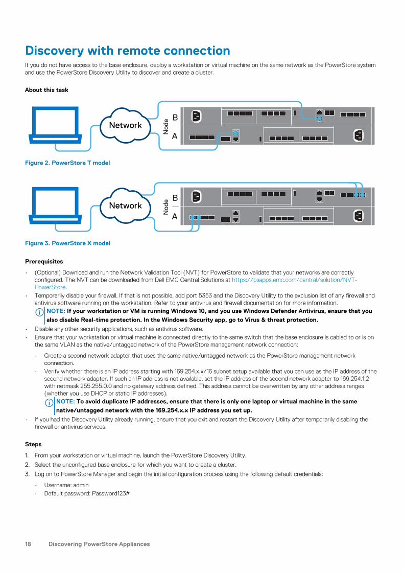
Discovery with remote connectionIf you do not have access to the base enclosure, deploy a workstation or virtual machine on the same network as the PowerStore systemand use the PowerStore Discovery Utility to discover and create a cluster.
About this task
B
ANode
Network
Figure 2. PowerStore T model
B
ANode
Network
Figure 3. PowerStore X model
Prerequisites
• (Optional) Download and run the Network Validation Tool (NVT) for PowerStore to validate that your networks are correctlyconfigured. The NVT can be downloaded from Dell EMC Central Solutions at https://psapps.emc.com/central/solution/NVT-PowerStore.
• Temporarily disable your firewall. If that is not possible, add port 5353 and the Discovery Utility to the exclusion list of any firewall andantivirus software running on the workstation. Refer to your antivirus and firewall documentation for more information.
NOTE: If your workstation or VM is running Windows 10, and you use Windows Defender Antivirus, ensure that you
also disable Real-time protection. In the Windows Security app, go to Virus & threat protection.
• Disable any other security applications, such as antivirus software.• Ensure that your workstation or virtual machine is connected directly to the same switch that the base enclosure is cabled to or is on
the same VLAN as the native/untagged network of the PowerStore management network connection:
• Create a second network adapter that uses the same native/untagged network as the PowerStore management networkconnection.
• Verify whether there is an IP address starting with 169.254.x.x/16 subnet setup available that you can use as the IP address of thesecond network adapter. If such an IP address is not available, set the IP address of the second network adapter to 169.254.1.2with netmask 255.255.0.0 and no gateway address defined. This address cannot be overwritten by any other address ranges(whether you use DHCP or static IP addresses).
NOTE: To avoid duplicate IP addresses, ensure that there is only one laptop or virtual machine in the same
native/untagged network with the 169.254.x.x IP address you set up.
• If you had the Discovery Utility already running, ensure that you exit and restart the Discovery Utility after temporarily disabling thefirewall or antivirus services.
Steps
1. From your workstation or virtual machine, launch the PowerStore Discovery Utility.
2. Select the unconfigured base enclosure for which you want to create a cluster.
3. Log on to PowerStore Manager and begin the initial configuration process using the following default credentials:
• Username: admin• Default password: Password123#
18 Discovering PowerStore Appliances
Port Usage
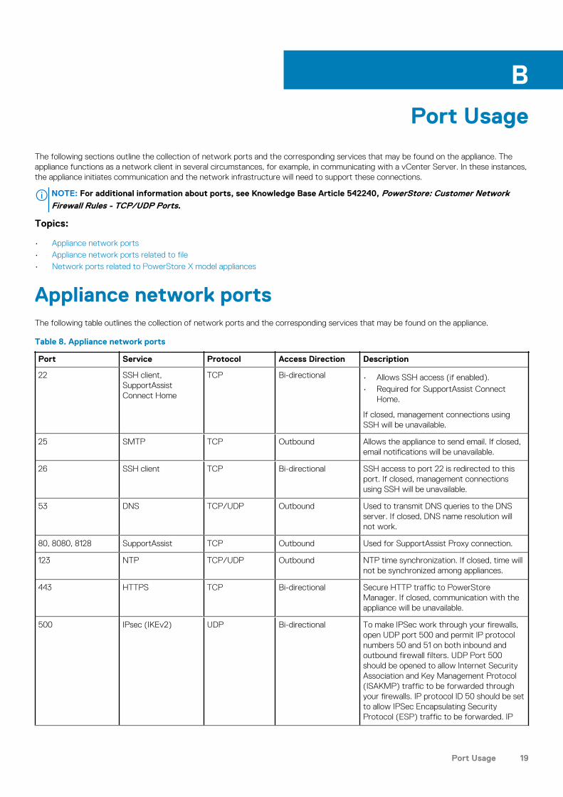
The following sections outline the collection of network ports and the corresponding services that may be found on the appliance. Theappliance functions as a network client in several circumstances, for example, in communicating with a vCenter Server. In these instances,the appliance initiates communication and the network infrastructure will need to support these connections.
NOTE: For additional information about ports, see Knowledge Base Article 542240, PowerStore: Customer NetworkFirewall Rules - TCP/UDP Ports.
Topics:
• Appliance network ports• Appliance network ports related to file• Network ports related to PowerStore X model appliances
Appliance network portsThe following table outlines the collection of network ports and the corresponding services that may be found on the appliance.
Table 8. Appliance network ports
Port Service Protocol Access Direction Description
22 SSH client,SupportAssistConnect Home
TCP Bi-directional • Allows SSH access (if enabled).• Required for SupportAssist Connect
Home.
If closed, management connections usingSSH will be unavailable.
25 SMTP TCP Outbound Allows the appliance to send email. If closed,email notifications will be unavailable.
26 SSH client TCP Bi-directional SSH access to port 22 is redirected to thisport. If closed, management connectionsusing SSH will be unavailable.
53 DNS TCP/UDP Outbound Used to transmit DNS queries to the DNSserver. If closed, DNS name resolution willnot work.
80, 8080, 8128 SupportAssist TCP Outbound Used for SupportAssist Proxy connection.
123 NTP TCP/UDP Outbound NTP time synchronization. If closed, time willnot be synchronized among appliances.
443 HTTPS TCP Bi-directional Secure HTTP traffic to PowerStoreManager. If closed, communication with theappliance will be unavailable.
500 IPsec (IKEv2) UDP Bi-directional To make IPSec work through your firewalls,open UDP port 500 and permit IP protocolnumbers 50 and 51 on both inbound andoutbound firewall filters. UDP Port 500should be opened to allow Internet SecurityAssociation and Key Management Protocol(ISAKMP) traffic to be forwarded throughyour firewalls. IP protocol ID 50 should be setto allow IPSec Encapsulating SecurityProtocol (ESP) traffic to be forwarded. IP
B
Port Usage 19
Port Service Protocol Access Direction Description
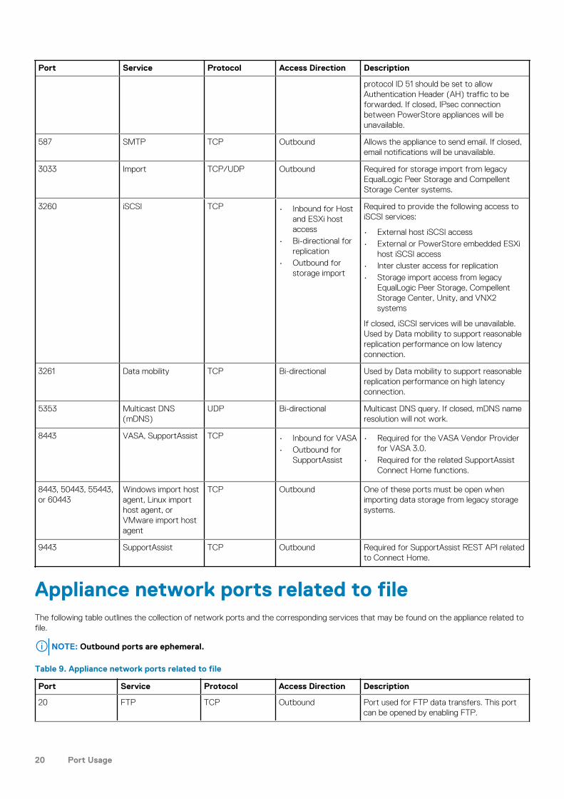
protocol ID 51 should be set to allowAuthentication Header (AH) traffic to beforwarded. If closed, IPsec connectionbetween PowerStore appliances will beunavailable.
587 SMTP TCP Outbound Allows the appliance to send email. If closed,email notifications will be unavailable.
3033 Import TCP/UDP Outbound Required for storage import from legacyEqualLogic Peer Storage and CompellentStorage Center systems.
3260 iSCSI TCP • Inbound for Hostand ESXi hostaccess
• Bi-directional forreplication
• Outbound forstorage import
Required to provide the following access toiSCSI services:
• External host iSCSI access• External or PowerStore embedded ESXi
host iSCSI access• Inter cluster access for replication• Storage import access from legacy
EqualLogic Peer Storage, CompellentStorage Center, Unity, and VNX2systems
If closed, iSCSI services will be unavailable.Used by Data mobility to support reasonablereplication performance on low latencyconnection.
3261 Data mobility TCP Bi-directional Used by Data mobility to support reasonablereplication performance on high latencyconnection.
5353 Multicast DNS(mDNS)
UDP Bi-directional Multicast DNS query. If closed, mDNS nameresolution will not work.
8443 VASA, SupportAssist TCP • Inbound for VASA• Outbound for
SupportAssist
• Required for the VASA Vendor Providerfor VASA 3.0.
• Required for the related SupportAssistConnect Home functions.
8443, 50443, 55443,or 60443
Windows import hostagent, Linux importhost agent, orVMware import hostagent
TCP Outbound One of these ports must be open whenimporting data storage from legacy storagesystems.
9443 SupportAssist TCP Outbound Required for SupportAssist REST API relatedto Connect Home.
Appliance network ports related to fileThe following table outlines the collection of network ports and the corresponding services that may be found on the appliance related tofile.
NOTE: Outbound ports are ephemeral.
Table 9. Appliance network ports related to file
Port Service Protocol Access Direction Description
20 FTP TCP Outbound Port used for FTP data transfers. This portcan be opened by enabling FTP.
20 Port Usage
Port Service Protocol Access Direction Description
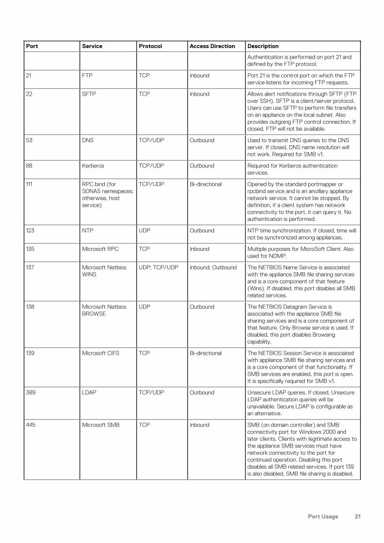
Authentication is performed on port 21 anddefined by the FTP protocol.
21 FTP TCP Inbound Port 21 is the control port on which the FTPservice listens for incoming FTP requests.
22 SFTP TCP Inbound Allows alert notifications through SFTP (FTPover SSH). SFTP is a client/server protocol.Users can use SFTP to perform file transferson an appliance on the local subnet. Alsoprovides outgoing FTP control connection. Ifclosed, FTP will not be available.
53 DNS TCP/UDP Outbound Used to transmit DNS queries to the DNSserver. If closed, DNS name resolution willnot work. Required for SMB v1.
88 Kerberos TCP/UDP Outbound Required for Kerberos authenticationservices.
111 RPC bind (forSDNAS namespaces;otherwise, hostservice)
TCP/UDP Bi-directional Opened by the standard portmapper orrpcbind service and is an ancillary appliancenetwork service. It cannot be stopped. Bydefinition, if a client system has networkconnectivity to the port, it can query it. Noauthentication is performed.
123 NTP UDP Outbound NTP time synchronization. If closed, time willnot be synchronized among appliances.
135 Microsoft RPC TCP Inbound Multiple purposes for MicroSoft Client. Alsoused for NDMP.
137 Microsoft NetbiosWINS
UDP; TCP/UDP Inbound; Outbound The NETBIOS Name Service is associatedwith the appliance SMB file sharing servicesand is a core component of that feature(Wins). If disabled, this port disables all SMBrelated services.
138 Microsoft NetbiosBROWSE
UDP Outbound The NETBIOS Datagram Service isassociated with the appliance SMB filesharing services and is a core component ofthat feature. Only Browse service is used. Ifdisabled, this port disables Browsingcapability.
139 Microsoft CIFS TCP Bi-directional The NETBIOS Session Service is associatedwith appliance SMB file sharing services andis a core component of that functionality. IfSMB services are enabled, this port is open.It is specifically required for SMB v1.
389 LDAP TCP/UDP Outbound Unsecure LDAP queries. If closed, UnsecureLDAP authentication queries will beunavailable. Secure LDAP is configurable asan alternative.
445 Microsoft SMB TCP Inbound SMB (on domain controller) and SMBconnectivity port for Windows 2000 andlater clients. Clients with legitimate access tothe appliance SMB services must havenetwork connectivity to the port forcontinued operation. Disabling this portdisables all SMB related services. If port 139is also disabled, SMB file sharing is disabled.
Port Usage 21
Port Service Protocol Access Direction Description
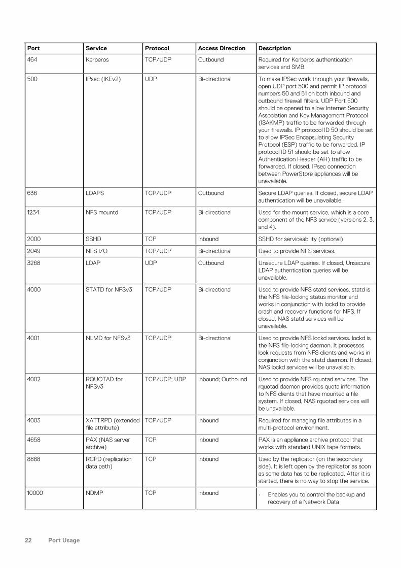
464 Kerberos TCP/UDP Outbound Required for Kerberos authenticationservices and SMB.
500 IPsec (IKEv2) UDP Bi-directional To make IPSec work through your firewalls,open UDP port 500 and permit IP protocolnumbers 50 and 51 on both inbound andoutbound firewall filters. UDP Port 500should be opened to allow Internet SecurityAssociation and Key Management Protocol(ISAKMP) traffic to be forwarded throughyour firewalls. IP protocol ID 50 should be setto allow IPSec Encapsulating SecurityProtocol (ESP) traffic to be forwarded. IPprotocol ID 51 should be set to allowAuthentication Header (AH) traffic to beforwarded. If closed, IPsec connectionbetween PowerStore appliances will beunavailable.
636 LDAPS TCP/UDP Outbound Secure LDAP queries. If closed, secure LDAPauthentication will be unavailable.
1234 NFS mountd TCP/UDP Bi-directional Used for the mount service, which is a corecomponent of the NFS service (versions 2, 3,and 4).
2000 SSHD TCP Inbound SSHD for serviceability (optional)
2049 NFS I/O TCP/UDP Bi-directional Used to provide NFS services.
3268 LDAP UDP Outbound Unsecure LDAP queries. If closed, UnsecureLDAP authentication queries will beunavailable.
4000 STATD for NFSv3 TCP/UDP Bi-directional Used to provide NFS statd services. statd isthe NFS file-locking status monitor andworks in conjunction with lockd to providecrash and recovery functions for NFS. Ifclosed, NAS statd services will beunavailable.
4001 NLMD for NFSv3 TCP/UDP Bi-directional Used to provide NFS lockd services. lockd isthe NFS file-locking daemon. It processeslock requests from NFS clients and works inconjunction with the statd daemon. If closed,NAS lockd services will be unavailable.
4002 RQUOTAD forNFSv3
TCP/UDP; UDP Inbound; Outbound Used to provide NFS rquotad services. Therquotad daemon provides quota informationto NFS clients that have mounted a filesystem. If closed, NAS rquotad services willbe unavailable.
4003 XATTRPD (extendedfile attribute)
TCP/UDP Inbound Required for managing file attributes in amulti-protocol environment.
4658 PAX (NAS serverarchive)
TCP Inbound PAX is an appliance archive protocol thatworks with standard UNIX tape formats.
8888 RCPD (replicationdata path)
TCP Inbound Used by the replicator (on the secondaryside). It is left open by the replicator as soonas some data has to be replicated. After it isstarted, there is no way to stop the service.
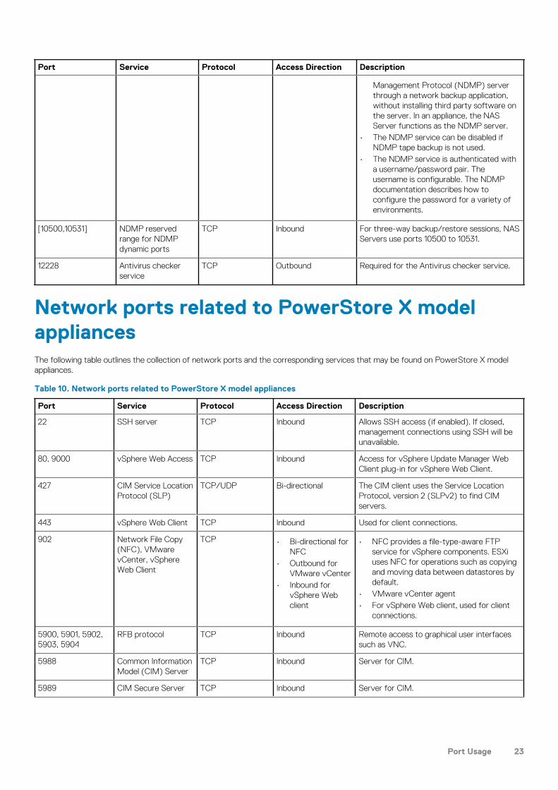
10000 NDMP TCP Inbound • Enables you to control the backup andrecovery of a Network Data
22 Port Usage
Port Service Protocol Access Direction Description
Management Protocol (NDMP) serverthrough a network backup application,without installing third party software onthe server. In an appliance, the NASServer functions as the NDMP server.
• The NDMP service can be disabled ifNDMP tape backup is not used.
• The NDMP service is authenticated witha username/password pair. Theusername is configurable. The NDMPdocumentation describes how toconfigure the password for a variety ofenvironments.
[10500,10531] NDMP reservedrange for NDMPdynamic ports
TCP Inbound For three-way backup/restore sessions, NASServers use ports 10500 to 10531.
12228 Antivirus checkerservice
TCP Outbound Required for the Antivirus checker service.
Network ports related to PowerStore X modelappliancesThe following table outlines the collection of network ports and the corresponding services that may be found on PowerStore X modelappliances.
Table 10. Network ports related to PowerStore X model appliances
Port Service Protocol Access Direction Description
22 SSH server TCP Inbound Allows SSH access (if enabled). If closed,management connections using SSH will beunavailable.
80, 9000 vSphere Web Access TCP Inbound Access for vSphere Update Manager WebClient plug-in for vSphere Web Client.
427 CIM Service LocationProtocol (SLP)
TCP/UDP Bi-directional The CIM client uses the Service LocationProtocol, version 2 (SLPv2) to find CIMservers.
443 vSphere Web Client TCP Inbound Used for client connections.
902 Network File Copy(NFC), VMwarevCenter, vSphereWeb Client
TCP • Bi-directional forNFC
• Outbound forVMware vCenter
• Inbound forvSphere Webclient
• NFC provides a file-type-aware FTPservice for vSphere components. ESXiuses NFC for operations such as copyingand moving data between datastores bydefault.
• VMware vCenter agent• For vSphere Web client, used for client
connections.
5900, 5901, 5902,5903, 5904
RFB protocol TCP Inbound Remote access to graphical user interfacessuch as VNC.
5988 Common InformationModel (CIM) Server
TCP Inbound Server for CIM.
5989 CIM Secure Server TCP Inbound Server for CIM.
Port Usage 23
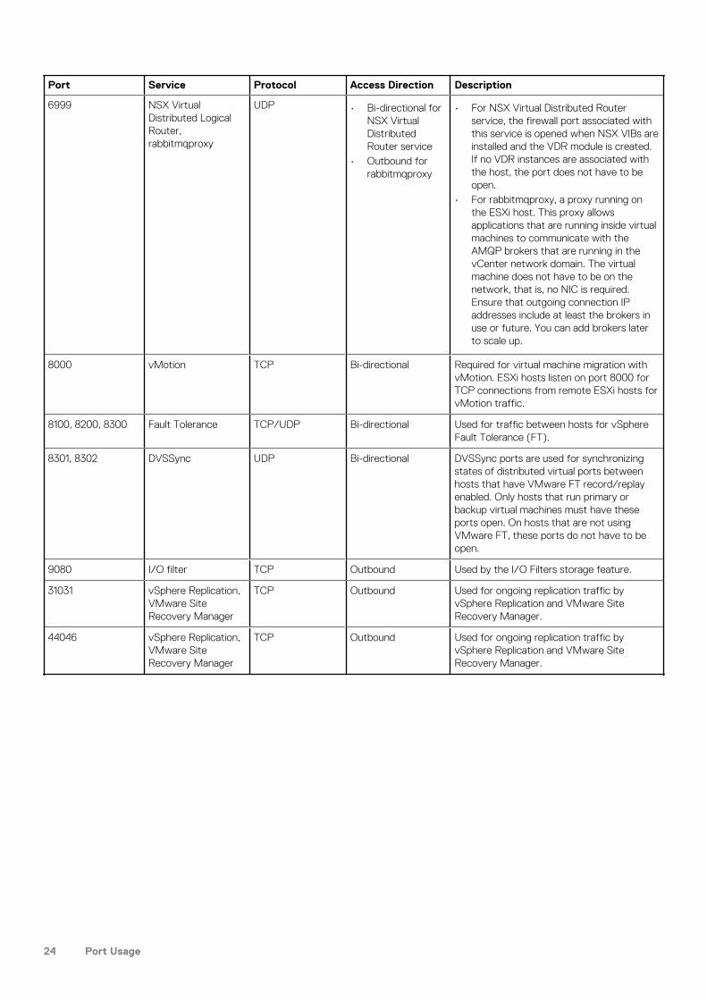
Port Service Protocol Access Direction Description
6999 NSX VirtualDistributed LogicalRouter,rabbitmqproxy
UDP • Bi-directional forNSX VirtualDistributedRouter service
• Outbound forrabbitmqproxy
• For NSX Virtual Distributed Routerservice, the firewall port associated withthis service is opened when NSX VIBs areinstalled and the VDR module is created.If no VDR instances are associated withthe host, the port does not have to beopen.
• For rabbitmqproxy, a proxy running onthe ESXi host. This proxy allowsapplications that are running inside virtualmachines to communicate with theAMQP brokers that are running in thevCenter network domain. The virtualmachine does not have to be on thenetwork, that is, no NIC is required.Ensure that outgoing connection IPaddresses include at least the brokers inuse or future. You can add brokers laterto scale up.
8000 vMotion TCP Bi-directional Required for virtual machine migration withvMotion. ESXi hosts listen on port 8000 forTCP connections from remote ESXi hosts forvMotion traffic.
8100, 8200, 8300 Fault Tolerance TCP/UDP Bi-directional Used for traffic between hosts for vSphereFault Tolerance (FT).
8301, 8302 DVSSync UDP Bi-directional DVSSync ports are used for synchronizingstates of distributed virtual ports betweenhosts that have VMware FT record/replayenabled. Only hosts that run primary orbackup virtual machines must have theseports open. On hosts that are not usingVMware FT, these ports do not have to beopen.
9080 I/O filter TCP Outbound Used by the I/O Filters storage feature.
31031 vSphere Replication,VMware SiteRecovery Manager
TCP Outbound Used for ongoing replication traffic byvSphere Replication and VMware SiteRecovery Manager.
44046 vSphere Replication,VMware SiteRecovery Manager
TCP Outbound Used for ongoing replication traffic byvSphere Replication and VMware SiteRecovery Manager.
24 Port Usage
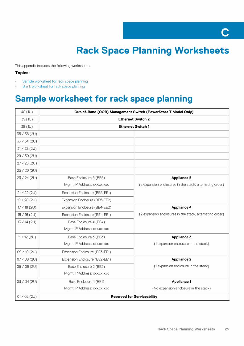
Rack Space Planning WorksheetsThis appendix includes the following worksheets:
Topics:
• Sample worksheet for rack space planning• Blank worksheet for rack space planning
Sample worksheet for rack space planning40 (1U) Out-of-Band (OOB) Management Switch (PowerStore T Model Only)
39 (1U) Ethernet Switch 2
38 (1U) Ethernet Switch 1
35 / 36 (2U)
33 / 34 (2U)
31 / 32 (2U)
29 / 30 (2U)
27 / 28 (2U)
25 / 26 (2U)
23 / 24 (2U) Base Enclosure 5 (BE5)
Mgmt IP Address: xxx.xx.xxx
Appliance 5
(2 expansion enclosures in the stack, alternating order)
21 / 22 (2U) Expansion Enclosure (BE5-EE1)
19 / 20 (2U) Expansion Enclosure (BE5-EE2)
17 / 18 (2U) Expansion Enclosure (BE4-EE2) Appliance 4
(2 expansion enclosures in the stack, alternating order)15 / 16 (2U) Expansion Enclosure (BE4-EE1)
13 / 14 (2U) Base Enclosure 4 (BE4)
Mgmt IP Address: xxx.xx.xxx
11 / 12 (2U) Base Enclosure 3 (BE3)
Mgmt IP Address: xxx.xx.xxx
Appliance 3
(1 expansion enclosure in the stack)
09 / 10 (2U) Expansion Enclosure (BE3-EE1)
07 / 08 (2U) Expansion Enclosure (BE2-EE1) Appliance 2
(1 expansion enclosure in the stack)05 / 06 (2U) Base Enclosure 2 (BE2)
Mgmt IP Address: xxx.xx.xxx
03 / 04 (2U) Base Enclosure 1 (BE1)
Mgmt IP Address: xxx.xx.xxx
Appliance 1
(No expansion enclosure in the stack)
01 / 02 (2U) Reserved for Serviceability
C
Rack Space Planning Worksheets 25

Blank worksheet for rack space planning40 (1U) Out-of-Band (OOB) Management Switch (PowerStore T Model Only)
39 (1U) Ethernet Switch 2
38 (1U) Ethernet Switch 1
35 / 36 (2U)
33 / 34 (2U)
31 / 32 (2U)
29 / 30 (2U)
27 / 28 (2U)
25 / 26 (2U)
23 / 24 (2U)
21 / 22 (2U)
19 / 20 (2U)
17 / 18 (2U)
15 / 16 (2U)
13 / 14 (2U)
11 / 12 (2U)
09 / 10 (2U)
07 / 08 (2U)
05 / 06 (2U)
03 / 04 (2U)
01 / 02 (2U) Reserved for Serviceability
26 Rack Space Planning Worksheets