Delivery specification CAD layout planning · Einführung - Introduction Seite 3 von 36 Page 3 of...
36
Ablage: BMW Partner Portal (https://b2b.bmw.com) Funktionsbereiche Technologien Montage CAD-Layoutplanung File: BMW Partner Portal (https://b2b.bmw.com) Function areas Technologies Assembly CAD layout planning BMW Group Technologie Montage Assembly technology BMW AG 80788 München © 2015 BMW AG Liefervorschrift CAD-Layoutplanung Technologie Montage 2015 Delivery specification CAD layout planning Assembly Technology 2015 Änderungshistorie - Change Documentation Version Version Datum Date Änderungen Changes Verantwortlich Responsible 1.0 29.09.2005 Grundlegende Überarbeitung der LV in Zusam- menhang mit Zusammenführung veralteter allge- meiner und technologiespezifischer LV; Integrati- on Partner Portal Basic revision of the DS in connection with bringing together outdated general DSs and DSs for a specific technology; integration of Partner Portal FT Layout Montage (Harnatt, Hornung, Keck, Schuppe) 1.1 07.05.2008 Anpassung Meilensteine (Kap. 2) Adaptations of milestones (chap. 2) FT Layout Montage (Hornung) 1.2 01.08.2014 Integration der englischen Fassung Integration of the English version FT Layout Montage
Transcript of Delivery specification CAD layout planning · Einführung - Introduction Seite 3 von 36 Page 3 of...
Ablage: BMW Partner Portal (https://b2b.bmw.com) Funktionsbereiche Technologien Montage CAD-Layoutplanung File: BMW Partner Portal (https://b2b.bmw.com) Function areas Technologies Assembly CAD layout planning
BMW Group Technologie Montage Assembly technology
BMW AG 80788 München
© 2015 BMW AG
Liefervorschrift CAD-Layoutplanung Technologie Montage 2015
Delivery specification CAD layout planning Assembly Technology 2015
Änderungshistorie - Change Documentation
Version Version
Datum Date
Änderungen Changes
Verantwortlich Responsible
1.0 29.09.2005 Grundlegende Überarbeitung der LV in Zusam-menhang mit Zusammenführung veralteter allge-meiner und technologiespezifischer LV; Integrati-on Partner Portal Basic revision of the DS in connection with bringing together outdated general DSs and DSs for a specific technology; integration of Partner Portal
FT Layout Montage (Harnatt, Hornung, Keck, Schuppe)
1.1 07.05.2008 Anpassung Meilensteine (Kap. 2) Adaptations of milestones (chap. 2)
FT Layout Montage
(Hornung)
1.2
01.08.2014 Integration der englischen Fassung
Integration of the English version
FT Layout Montage

BMW Group Liefervorschrift CAD-Layoutplanung Technologie Montage Methoden / Standards
Delivery specification Version 01/2015
CAD layout planning Version 01/2015
Seite 2 von 36 Page 2 of 36
Version
08/2014
Inhaltsverzeichnis - Table of contents
1 Einführung - Introduction .......................................................................................................................... 3
1.1 Zielsetzung der Layoutplanung - Objective of layout planning ................................................................. 3
1.2 Partner Portal - Partner Portal ................................................................................................................... 4
1.3 Gültigkeit - Validity ..................................................................................................................................... 4
1.4 Ansprechpartner - Contact partners .......................................................................................................... 5
2 Lieferzeiten und Lieferumfang - Delivery times and scope of delivery ................................................ 6
2.1 Änderungsmanagement - Change management ...................................................................................... 7
2.2 Ergänzende Daten - Supplementary data ................................................................................................. 8
3 Planungssoftware - Planning software .................................................................................................... 9
3.1 Einsatz des Moduls Fördertechnik - Use of the conveyor technology module ....................................... 10
3.2 Einsatz des Moduls Bühnentechnik - Use of the platform technology module ....................................... 10
4 Konfiguration und Einstellungen - Configuration and settings .......................................................... 11
4.1 seed-Datei (seed3d_mm_v8.dgn) - Seed file (seed3d_mm_v8.dgn) ..................................................... 11
4.2 dgnlib-Konfigurationsdateien – dgnlib-Configuration files ....................................................................... 12
4.3 Ressourcen-Dateien - Resource files ..................................................................................................... 13
4.4 Farbtabelle (bmwcolour.tbl) - Colour table (bmwcolour.tbl) .................................................................... 13
4.5 TRICAD-Module Fördertechnik und Bühnentechnik – TRICAD-module conveyor technology and platform technology ........................................................................................................................................... 14
5 Datenbereitstellung - Data provision ..................................................................................................... 15
5.1 Übertragungswege - Transmission pathways ......................................................................................... 15
5.2 Dateinamen - File names ........................................................................................................................ 17
6 CAD-Regeln und Arbeitsweise - CAD rules and working method ...................................................... 19
6.1 Nicht zugelassene MicroStation-Funktionen – Not permitted Microstation functions ............................. 19
6.2 Referenzen und Arbeitsumgebung - References and working environment .......................................... 20
6.3 Leerdateien - Empty files ......................................................................................................................... 20
6.4 Bezugspunkt (Referenzpunkt) - Reference point .................................................................................... 20
6.5 Ebenenbelegung - Level assignment ...................................................................................................... 21
6.6 Farben - Colour ....................................................................................................................................... 22
6.7 Text- und Linienstile - Text and line styles .............................................................................................. 23
6.8 Bibliotheken und Zellen - Libraries and cells ........................................................................................... 23
6.8.1 Zellen (Urzellen) - Cells (original cells) ................................................................................................. 23
6.8.2 Pseudozellen - Pseudo cells ................................................................................................................ 24
6.8.3 Verschachtelte Zellen (nested cells) - Nested cells ............................................................................. 24
6.9 Zeichnungsrahmen, Zeichnungskopf und Änderungshistorie - Drawing frame, drawing header and modification record ............................................................................................................................................ 24
6.10 Speicherzustand und Qualitätsprüfung - Storage format and quality check ........................................... 25
7 Detaillierungsgrad - Level of detail ........................................................................................................ 28
7.1 Detaillierung im Planungsprozess - Detailing in the planning process ................................................... 28
7.2 Gestaltungsbeispiele - Design examples ................................................................................................ 31
BMW Group Liefervorschrift CAD-Layoutplanung Technologie Montage Methoden / Standards Assembly technology Methods / standard
Kapitel/Chapter 1 Stand/Version 01/2015
Einführung - Introduction
Seite 3 von 36 Page 3 of 36
1 Einführung - Introduction
Diese Liefervorschrift beschreibt, wie die Partner von BMW für die Technologie Mon-tage ihre Umfänge für die CAD-Layoutplanung mit dem Planungssystem MicroStation bereitzustellen haben. In die-ser Liefervorschrift werden ausschließlich die CAD-Layoutumfänge für die Technolo-gie Montage geregelt. Weitere Liefervor-schriften anderer Technologien (z.B. Karos-seriebau, Oberfläche, etc.) oder anderer Themenbereiche (z.B. Fertigungsmittelkon-struktion, Steuerungstechnik, etc.) haben keine Gültigkeit für die Layoutplanung.
This delivery specification describes how BMW partners have to present their Assem-bly Plant Projects for CAD layout planning with the MicroStation planning system. This delivery specification exclusively regulates the CAD layouts for Assembly Plant. Addi-tional delivery specifications for other tech-nologies (e.g. Bodyshop, Paintshop, etc.) or other topics (e.g. production equipment de-sign, control technology, etc.) are not valid for the layout planning.
Projektspezifische Regelungen und Erweite-rungen werden im Rahmen des Kick Off Gespräches festgelegt und protokolliert.
Project-specific rules and additions will be defined at the start of the project as part of the order clarification with the CAD contact partner of the department which placed the order.
1.1 Zielsetzung der Layoutplanung - Objective of layout planning
Die Zielsetzung der Layoutplanung bei BMW ist die Darstellung aller Gewerke (Ge-bäude, Einrichtungs- und Produktionstech-nik, Medienversorgung, etc.) hinsichtlich ihrer markanten Geometrien (Haupt- und Außenkonturen). Durch die Layoutplanung werden im Wesentlichen die zur Verfügung stehenden Flächen aufgeteilt und Schnitt-stellen zwischen einzelnen Gewerken defi-niert und abgesichert. Die Layoutplanung wird sowohl in 2D als auch in 3D ausgeführt (soweit in der Ausschreibung nicht ander-weitig geregelt).
The objective of layout planning at BMW is to represent all installations (buildings, facili-ties, production engineering, and services supply, etc.) with reference to their distinc-tive geometries (main and exterior con-tours). Layout planning basically divides the available areas, and defines and safeguards interfaces between Technologies. Layout planning is configured in both 2D and 3D (unless specified otherwise in the call for tenders).
Um die vollständige Darstellung eines Lay-outs zu ermöglichen, darf ein Layoutplan keine Konstruktionsdetails, wie z.B. Norm-teile und Verbindungselemente enthalten, die im Rahmen der Layoutplanung keine wesentlichen Informationen darstellen (Re-duktion des Datenumfangs). Die dazu not-wendige Gestaltung, technische Randbe-
In order to obtain a complete layout, the layout plan must not to contain any con-struction details such as standard parts and connection elements are, in the context of the layout planning, not constituted of es-sential information (reduction in amount of data). The necessary design, technical boundary conditions and working methods
BMW Group Liefervorschrift CAD-Layoutplanung Technologie Montage Methoden / Standards Assembly technology Methods / standard
Kapitel/Chapter 1 Stand/Version 01/2015
Einführung - Introduction
Seite 4 von 36 Page 4 of 36
dingungen und Arbeitsweisen sowie der Detaillierungsgrad der Layouts (siehe Kapi-tel 7) sind in dieser Liefervorschrift be-schrieben.
which are required for this, as well as the level of detail in the layout (see chapter 7) are described in this delivery specification.
Die Layoutplanung ergänzt die Anlagen- und Fertigungsmittelkonstruktion (kein Er-satz). Für die Konstruktionsumfänge freige-gebene Arbeitsweisen, Methoden und Sys-teme werden anwendungs- und technolo-giespezifisch von den Fachbereichen gere-gelt. Diese Konstruktionsbereiche sind nicht Umfang dieser Liefervorschrift
The layout planning supplements (but does not replace) the system and production equipment design. Working methods, meth-ods and systems approved for the design items are regulated by the departments specifically for the applications and technol-ogies. The design departments are not part of this delivery specification.
1.2 Partner Portal - Partner Portal
Das Partner Portal ist die Schnittstelle und Kommunikationsplattform zwischen der BMW Group und ihren Partnern. Das Part-ner Portal ist im Internet unter folgender Ad-resse erreichbar: https://b2b.bmw.com/
The Partner Portal is the interface and communication platform between the BMW Group and its partners. The Partner Portal can be accessed on the Internet at the fol-lowing address: https://b2b.bmw.com/
Die Inhalte und Applikationen im Partner Portal sind teilweise zugriffsgeschützt und nur für zugelassene Anwender abrufbar. Zulassungen können direkt auf der Startsei-te des Partner Portals beantragt werden.
Some of the contents and applications in the Partner Portal have access protection, and can only be accessed by authorized users. Authorizations can be applied for directly on the homepage of the Partner Portal.
Bei Verweisen auf Inhalte im Partner Portal wird der jeweilige Navigationspfad angege-ben, unter dem die referenzierten Informati-onen abgefragt werden können. Informatio-nen und Richtlinien der Technologie Monta-ge finden Sie unter:
For reference to contents in the Partner Por-tal, the corresponding navigation path is specified and can be used for requesting the referenced information. Information and guidelines of Assembly technology can be found at:
Funktionsbereiche Technologien Montage
Function areas Technologies Assembly
1.3 Gültigkeit - Validity
Es gilt die zum Zeitpunkt der Auftragsverga-be aktuelle Version der Liefervorschrift und darin festgelegte Arbeitsweisen und Konfi-gurationen. Der Auftragnehmer (AN) hat die Aktualität der ihm vorliegenden Dokumente und Einstellungen eigenverantwortlich zu prüfen. Die Liefervorschrift ist im Partner Portal unter folgendem Pfad zu finden:
The latest version of the delivery specifica-tion at the date when the order is placed is valid, with the therein contained working methods and configurations. The contract recipient (CR) is responsible to check and confirm that the present documents and set-tings are up to date. The delivery specifica-tion can be found in the Partner Portal at the
BMW Group Liefervorschrift CAD-Layoutplanung Technologie Montage Methoden / Standards Assembly technology Methods / standard
Kapitel/Chapter 1 Stand/Version 01/2015
Einführung - Introduction
Seite 5 von 36 Page 5 of 36
following path:
Funktionsbereiche Technologien Montage CAD-Layoutplanung
Function areas Technologies As-sembly CAD layout planning
Projektspezifische Änderungen der Liefer-vorschrift, Arbeitsweise oder Konfiguration bedürfen der Schriftform und gelten als ge-nehmigt, wenn sie vom zuständigen CAD-Ansprechpartner und dem Projektleiter seitens des Auftraggebers (AG) gegenge-zeichnet sind. Alle Regelungen gelten auch für Unterlieferanten, die durch den AN be-auftragt werden. Die Einhaltung ist durch den AN sicherzustellen.
Project-specific changes to the delivery specification, working method or configura-tion must be done in writing, and are re-garded as approved if they have been coun-tersigned by the responsible CAD contact partner and the project manager of the con-tract giver (CG). All regulations also apply to sub-suppliers which are assigned by the CR. Compliance shall be ensured by the CR.
1.4 Ansprechpartner - Contact partners
Bei Rückfragen oder Klärungsbedarf ist der AN verpflichtet mit dem CAD-Ansprechpartner der beauftragenden Fachabteilung seitens AG Kontakt aufzu-nehmen.
In the event of queries or if clarification is required, the CR is obliged to contact the CAD contact partner of the CG's department which is placing the order.
Die CAD-Ansprechpartner der einzelnen Standorte sind im Partner Portal unter fol-gendem Pfad zu finden:
The CAD contact partners of the individual sites can be found in the Partner Portal at the following path:
Funktionsbereiche Technologien Montage CAD-Layoutplanung
Function areas Technologies As-sembly CAD layout planning

BMW Group Liefervorschrift CAD-Layoutplanung Technologie Montage Methoden / Standards Assembly technology Methods / standard
Kapitel/Chapter 2 Stand/Version 01/2015
Lieferzeiten und Lieferumfang - Delivery times and scope of delivery
Seite 6 von 36 Page 6 of 36
2 Lieferzeiten und Lieferumfang - Delivery times and scope of delivery
Im Planungsprozess werden nach der Be-auftragung die anfangs unscharfen Pla-nungsdaten im Zuge der Feinplanung durch den AN zu konkreten Ausführungslayouts detailliert. Nach Aufbau der Anlage doku-mentiert der AN in den Layoutplänen die tatsächliche Umsetzung beim AG.
In the planning process immediately after the order placement, the initial unclear plan-ning data needs to be clarified in detail by the CR to create clear implementable lay-outs. After the installation of the site the CR needs to keep records in the layout plans about the actual realization at the CG.
Soweit nicht projektspezifisch anderweitig vorgegeben, sind im Projektverlauf fünf Mei-lensteine zur Übergabe von Layoutdaten vorgesehen. Zu den Meilensteinen sind, in Absprache mit dem CAD-Ansprechpartner des beauftragenden Fachbereichs, immer komplette Datensätze zu liefern.
Unless specified otherwise for the specific project, five milestones are provided for the handover of the layout data in the course of the project. Complete data records shall always be supplied for the milestones in consultation with the CAD contact partner of the department placing the order.
Freigabe der
KonstruktionAufstellplan
Bestands-
dokumentation
„as built“1 2 3 4
Lieferant erarbeitet
ein Entwurfslayout
sowie einen
Terminplan
Lieferant erarbeitet
ein Konstruktions-
layout zur Freigabe
Lieferant liefert Aus-
führungslayout vor
Aufbau des
beauftragten Umfangs
Lieferant liefert zur
Vorabnahme ein
aktualisiertes Layout
„as built“
Auftragslayout Freigabelayout Ausführungs-
layout
Bestandslayout
Verhandlungs-
zeitraum mit
möglichen
Lieferanten
Kick Off/
CAD
Startgespräch0
Vergabe
Beauftragung gemäß
Liefervorschrift
Abbildung 1: Meilensteine zur Abgabe der Layouts
Release of the
constructionFloor plan
“As built“
documentation1 2 3 4
Supplier has to
develop a concept
layout and a time
plan
Supplier has to
develop a construction
layout for release
Supplier has to deliver
a floor plan before start
of installation
Supplier delivers an
updated “as build“
layout at preacceptance
Contract layout Release layout Implementation
layout
“As build“ layout
0
Negotiation
time frame with
possible
suppliers
Kick Off/CAD
Opening
discussion0
Placement
Assignment
according delivery
specification
Figure 1: Milestones for handover of the layouts

BMW Group Liefervorschrift CAD-Layoutplanung Technologie Montage Methoden / Standards Assembly technology Methods / standard
Kapitel/Chapter 2 Stand/Version 01/2015
Lieferzeiten und Lieferumfang - Delivery times and scope of delivery
Seite 7 von 36 Page 7 of 36
Meilenstein 0 Vergabe Unmittelbar nach der Vergabe des Auftra-ges an den Lieferanten ist das Kick Off-Gespräch durchzuführen. In diesem Termin werden dem AN vom AG (vom entspre-chenden Layoutplaner) alle notwendigen Unterlagen und Vorlagendateien überge-ben.
Milestone 0 Placement The Kick Off-Meeting has to take place im-mediately after the order is placed at the supplier. In this appointment all necessary documents and draft data sets are to be handed over from the CG (relevant layout planer) to the CR.
Meilenstein 1 Auftragslayout
Nach dem Startgespräch mit dem AN ist zeitnah (ca. zwei Wochen nach Auftrags-vergabe) das Layout des aktuellen Plan-standes als Referenz für die Integration in die benachbarten Gewerke zu liefern.
Milestone 1 Contract layout
Shortly after order placement (approx. two weeks after order placement), the layout of the current planning status needs to be supplied as a reference for integration into the adjacent installations.
Meilenstein 2 Freigabelayout
Nach Ausführung der Feinplanung ist zur Freigabe des Konstruktionsentwurfs ein Freigabelayout zu liefern.
Milestone 2 Release layout
After the fine planning, a release layout needs to be supplied for release of the de-sign draft.
Meilenstein 3 Ausführungslayout
Vor dem Aufbau des Lieferumfangs beim AG ist ein Ausführungslayout zu liefern, dass die Modifikationen seit der Konstrukti-onsfreigabe dokumentiert.
Milestone 3 Implementation layout
Before the scope of supply is set up at the CG, an implementation layout needs to be supplied which documents the modifications since the design release.
Meilenstein 4 Bestandslayout
Zur Vorabnahme des Lieferumfangs ist das aktualisierte Layout zur Dokumentation des Zustands „wie gebaut“ bei Abnahme des vereinbarten Lieferumfanges zu liefern.
Dabei hat der AN eine Datei mit dem 2D-Layout und eine Datei mit dem 3D-Layout dem AG zu übergeben.
Milestone 4 ”As built” layout
For preliminary acceptance of the scope of supply, the updated layout which documents the "as built" status has to be supplied.
Therewith the CR has to handover a file with a 2D layout and a file with a 3D layout to the CG.
2.1 Änderungsmanagement - Change management
Der AN hat bei layoutrelevanten Änderun-gen seines Planungsumfangs dem AG auch zwischen den Meilensteinen aktualisierte Daten zur Verfügung zu stellen. Dabei ist es ausreichend nur die Referenzen mit geän-derten Umfängen zu übertragen (Anm.: es
In the event of layout-relevant changes to the scope of planning, the CR shall provide updated data to the CG, in addition to the milestones. In this case, it is sufficient to transfer only the references with changed items (Note: only complete references are

BMW Group Liefervorschrift CAD-Layoutplanung Technologie Montage Methoden / Standards Assembly technology Methods / standard
Kapitel/Chapter 2 Stand/Version 01/2015
Lieferzeiten und Lieferumfang - Delivery times and scope of delivery
Seite 8 von 36 Page 8 of 36
werden immer vollständige Referenzen übertragen, nicht nur die geänderten Um-fänge). Als layoutrelevant sind alle Ände-rungen einzustufen die sowohl die Außen-konturen als auch die Schnittstellen zu an-deren Gewerken betreffen (z.B. erhöhter Flächenbedarf für Versorgung einer Anla-ge).
handed over, not just the changed items). All changes are classified as layout-relevant if they relate to both the external contours and to the interfaces to other Technologies (e.g. increased surface area requirement to accommodate a system).
Notwendige Änderungen an Nachbargewer-ken, die nicht in den Auftragsumfang des AN fallen (z.B. Deckendurchbruch für He-ber), sind in separaten Zeichnungen zu do-kumentieren, beim AG einzusteuern und genehmigen zu lassen (siehe auch Kapi-tel 6.2).
Necessary changes to adjacent Technolo-gies, which are not part of the scope of de-livery of the CR (e.g. penetration of the floor for lifting gear) shall be documented in sep-arate drawings; these shall be integrated at the CG and require approval (see also chapter 6.2).
Änderungen an Nachbargewerken oder Produktdaten, die für den AN relevant sind, werden durch den AG kommuniziert und bei Verfügbarkeit der Daten durch den AG be-reitgestellt. Der AN hat den Empfang der Daten per E-Mail zu bestätigen.
Changes to adjacent Technologies or prod-uct data which are relevant to the CR have to be communicated by the CG and if the data sets are available it will be provided by the CG. The CR has to confirm the receipt of the data by E-Mail.
2.2 Ergänzende Daten - Supplementary data
Zusätzlich zu den Layoutdaten sind vom AN folgende Umfänge bei jeder Datenbereitstel-lung mitzuliefern.
In addition to the layout data, the CR shall also supply the following items with each data delivery.
Lieferschein CAD Layout
Der Lieferschein umfasst eine Auflistung aller bereitgestellten Dateien (Layoutdaten und ergänzende Daten) und ist als Doku-mentation des gelieferten Umfangs bei jeder Datenbereitstellung vom AN anzufertigen. Die für den Lieferschein zu verwendende Vorlage ist im Partner Portal unter folgen-dem Navigationspfad abgelegt:
Delivery Note CAD layout data
The delivery note includes a list of all rele-vant layout changes (layout data and sup-plementary data) and has to be documented by the CR and provided with every hando-ver. The template to be used for the change notice is stored in the Partner Portal under the following navigation path:
Funktionsbereiche Technologien Montage CAD-Layoutplanung
Function areas Technologies As-sembly CAD layout planning
Zellbibliotheken
Im Rahmen des Projekts verwendete Zellen sind in Form von Zellbibliotheken zu liefern (siehe auch Kapitel 6.8).
Cell libraries
Cells used as part of the project shall be supplied in the form of cell libraries (see al-so chapter 6.8).

BMW Group Liefervorschrift CAD-Layoutplanung Technologie Montage Methoden / Standards Assembly technology Methods / standard
Kapitel/Chapter 3 Stand/Version 01/2015
Planungssoftware - Planning software
Seite 9 von 36 Page 9 of 36
3 Planungssoftware - Planning software
Für die Layoutplanung in der Technologie Montage sind ausschließlich folgende Soft-wareprodukte und –module einzusetzen:
The following software products and mod-ules shall be exclusively used for the layout planning in the Assembly Technology:
Produkt Hersteller Anwendungen
MicroStation Bentley Systems http://www.bentley.de
Basisplattform
TRICAD FT (TRICAD MS Fördertechnik)
ITandFactory GmbH http://www.itandfactory.com
Modul zur Planung von Fördertechnik
TRICAD BT (TRICAD MS Bühnentechnik)
ITandFactory GmbH http://www.itandfactory.com
Modul zur Stahlbau- und Bühnenplanung
Tabelle 1: Einzusetzende Software für die Layoutplanung
Product Manufacturers Applications
MicroStation Bentley Systems http://www.bentley.de
Basic platform
TRICAD FT (TRICAD MS Conveyor tech-nology)
ITandFactory GmbH http://www.itandfactory.com
Module for planning con-veyor technology
TRICAD BT (TRICAD MS Platform tech-nology)
ITandFactory GmbH http://www.itandfactory.com
Module for steel fabrication and platform planning
Table 1: Software to be used for the layout planning
CAD-Layouts sind auf Basis der zur Verfü-gung gestellten Leerdateien (siehe auch Kapitel 6.1) als MicroStation dgn-Dokument mit bei BMW aktuellen MicroStation-Version zu liefern. Eine Konvertierung der CAD-Daten aus anderen Produkten oder Daten-formaten ist nicht zugelassen.
CAD layouts shall be delivered on the basis of the provided empty files (see also chap-ter 6.1) as a MicroStation dgn document in the MicroStation version currently used at BMW. It is not permitted to convert CAD data sets from other products or data for-mats.
Software-Release wechsel seitens BMW sind vom AN zeitgleich umzusetzen, sofern dies für einen erfolgreichen Projektablauf erforderlich ist. Die BMW-seitig aktuellen Software-Versionen sind im Partner Portal unter folgendem Pfad zu finden:
Software release changes at BMW shall be implemented at the same time by the CR if this is necessary for successful project han-dling. The software versions currently used at BMW can be found in the Partner Portal at the following path:

BMW Group Liefervorschrift CAD-Layoutplanung Technologie Montage Methoden / Standards Assembly technology Methods / standard
Kapitel/Chapter 3 Stand/Version 01/2015
Planungssoftware - Planning software
Seite 10 von 36 Page 10 of 36
Funktionsbereiche Technologien CAD-Fabrikplanung
Function areas Technologies CAD factory planning
3.1 Einsatz des Moduls Fördertechnik - Use of the conveyor technology module
Das Modul Fördertechnik ist vorrangig für die Vorplanung entwickelt worden. Es er-möglicht eine effiziente Planung eines kom-binierten 2D-/3D-Layouts für Hänge- und Flurfördersysteme. Aufgrund der Parametrik ist eine schnelle Modifikation und Anpas-sung aller Objekte möglich.
The conveyor technology module has pri-marily been developed for preliminary plan-ning. It permits efficient planning of a com-bined 2D/3D layout for overhead and floor conveyor systems. The parameters shall make it possible for all objects to be modi-fied and adapted quickly.
Mit zunehmendem Planungsfortschritt ist die Detaillierung der CAD-Objekte des Förder-technik-Moduls für bestimmte Anlagenkom-ponenten nicht ausreichend. Entsprechende Komponenten sind mit MicroStation Grund-funktionalitäten zu modellieren.
With the advancement in planning technolo-gy, the detail of the CAD objects of the con-veyor technology module for certain system components is not sufficient. These compo-nents shall be modeled in the MicroStation basic functions.
3.2 Einsatz des Moduls Bühnentechnik - Use of the platform technology module
Das Modul Bühnentechnik ist ein kombinier-tes Bühnen- und Stahlbaumodul zur Erstel-lung von 2D- und 3D-Konstruktionen. Das Bühnenmodul ist für die Modellierung von Stahlbauten (z.B. Bühnen, Abhängungen, Bandoberkonstruktionen, etc.) und Schutz-einrichtungen (z.B. Geländer, Rammschutz, etc.) einzusetzen.
The platform technology module is a com-bined platform and steel fabrication module for creating 2D and 3D designs. The plat-form module shall be used for modelling steel fabrications (e.g. platforms, suspen-sions, line superstructures, etc.) and protec-tive devices (e.g. railings, crash barriers, etc.).
Um die Datenmenge der CAD-Layouts so gering wie möglich zu halten sind Treppen- und Bühnenauflagen mit dem Bühnenmodul als einfache Auflage zu modellieren (d.h. keine detaillierte Darstellung von Gitterros-ten, etc.). Schutznetze sind mit TRICAD BT grobmaschig darzustellen.
In order to keep the amount of data in the CAD layouts as low as possible, stair and platform coverings need to be modelled with the platform module as a simple covering (i.e. no detailed representation of mesh panels, etc.). Protective nets should be pre-sented with a coarse mesh using TriCAD BT.
BMW Group Liefervorschrift CAD-Layoutplanung Technologie Montage Methoden / Standards Assembly technology Methods / standard
Kapitel/Chapter 4 Stand/Version 01/2015
Konfiguration und Einstellungen - Configuration and settings
Seite 11 von 36 Page 11 of 36
4 Konfiguration und Einstellungen - Configuration and set-tings
Der AN hat die im Folgenden benannten Einstellungen umzusetzen und bereitgestell-te Konfigurationsdateien für die Arbeit mit MicroStation und TRICAD zu verwenden. Diese Prämissen sind die Voraussetzung dafür, dass vom AN gelieferte CAD-Layouts beim AG in vorhandene Umfänge und ent-sprechende Arbeitsweisen integriert werden können.
The CR is responsible to implement the fol-lowing named settings and has to use the supplied configuration files for working with MicroStation and Tricad. The reason for this is that the CAD layouts to be supplied by the CR can be integrated by the CG with the existing setup and corresponding working methods.
Für Konfigurationsdateien ist als Installati-onshinweis das jeweilige Verzeichnis zur Ablage der Dateien unter einer MicroStation Standard-Installation angegeben. Der ggf. spezifische Ablageort in der Arbeitsumge-bung des AN muss durch den AN mit sei-nem Administrator bzw. Distributor geklärt werden.
For configuration files, an installation note shall be provided which is the corresponding folder for storing the files under a MicroStation standard installation. If a stor-age location is specified in the working envi-ronment of the CR, this shall be clarified by the CR with his administrator or distributor.
Der AN muss die Konfigurationsdateien zum Projektstart im Partner Portal unter folgen-dem Pfad abrufen (zip-Archiv mit allen Kon-figurationsdateien):
The CR must call up the configuration files in the Partner Portal at the start of the pro-ject from the following path (zip archive with all configuration files):
Funktionsbereiche Technologien Montage CAD-Layoutplanung
Function areas Technologies As-sembly CAD layout planning
4.1 seed-Datei (seed3d_mm_v8.dgn) - Seed file (seed3d_mm_v8.dgn)
Seed-Dateien dienen in MicroStation als Vorlage um neue Pläne zu erstellen. Da-durch werden wichtige Einstellungen, wie z.B. die Lage des globalen Ursprungs (glo-bal origin), die Arbeitseinheiten und die Auf-lösung vorgegeben. Der Rückgriff auf eine seed-Datei erspart die Anpassung der Ein-stellungen bei jeder Erstellung einer neuen DGN-Datei.
Seed files are used in MicroStation as a template for creating new plans. This means important settings such as the position of the global origin, the work units and the res-olution are specified. Resorting to a seed file means there is no need to adapt the set-tings every time a new DGN file is created.
Die bereitgestellte Seed-Datei seed3d_mm_v8.dgn ist in Absprache mit dem CAD-Ansprechpartner des beauftra-genden Fachbereichs zu verwenden, wenn explizit keine Leerdateien (siehe Kapitel 6.3)
The provided seed3d_mm_v8.dgn seed file has to be used in consultation with the CAD contact partner of the department placing the order if no empty files (see chapter 6.3) have explicitly been provided by the CG.

BMW Group Liefervorschrift CAD-Layoutplanung Technologie Montage Methoden / Standards Assembly technology Methods / standard
Kapitel/Chapter 4 Stand/Version 01/2015
Konfiguration und Einstellungen - Configuration and settings
Seite 12 von 36 Page 12 of 36
vom AG bereitgestellt werden.
Hinweis Die Bereitstellung von Leerdateien durch den AG ist zu bevorzugen. Sie werden durch den CAD-Ansprechpartner direkt im ProjectWise angelegt, enthalten alle relevanten Vor-einstellungen und im Rahmen der Namenskonvention ist durch ProjectWise bereits eine eindeutige Plannummer vorgegeben.
Installationshinweis seed-Dateien sind unter einer MicroStation-Standardinstallation im Verzeichnis ..\bentley\workspace\system\seed\ abzulegen.
Note Provision of empty files by the CG shall be preferred. They are created by the CAD con-tact partner directly in ProjectWise and contain all relevant default settings. As part of a naming convention, a unique plan number is already specified by ProjectWise.
Installation note Seed files shall be stored under a MicroStation standard installation, in the ..\bentley\workspace\system\seed\ folder.
4.2 dgnlib-Konfigurationsdateien – dgnlib-Configuration files
Durch mehrere dgnlib-Konfigurationsdateien werden alle im BMW-Umfeld verwendeten Ebenen (siehe Kapitel 6.4) und Filter für den Ebenenmanager definiert.
All levels (see chapter 6.4) and filters used in the BMW environment are defined for the level manager by several dgnlib-configuration files.
Installationshinweis dgnlib-Konfigurationsdateien sind unter einer MicroStation-Standardinstallation im Ver-zeichnis ..\bentley\workspace\system\dgnlib\ abzulegen.
Installation note dgnlib configuration files shall be stored under a MicroStation standard installation, in the..\bentley\workspace\system\dgnlib\ folder.

BMW Group Liefervorschrift CAD-Layoutplanung Technologie Montage Methoden / Standards Assembly technology Methods / standard
Kapitel/Chapter 4 Stand/Version 01/2015
Konfiguration und Einstellungen - Configuration and settings
Seite 13 von 36 Page 13 of 36
4.3 Ressourcen-Dateien - Resource files
Über Ressourcen-Dateien (rsc-Dateien) werden systemseitig sowohl Linien- als auch Textstile definiert und bereitgestellt. Der AN hat folgende rsc-Dateien zu ver-wenden:
Both line and text styles are defined and provided in the system using resource files (rsc files). The CR shall use the following rsc files:
font_bmw.rsc
montage_lstyle.rsc
abbruch_linie.rsc
font_bmw.rsc
montage_lstyle.rsc
abbruch_linie.rsc
Installationshinweis rsc-Konfigurationsdateien sind unter einer MicroStation-Standardinstallation im Verzeich-nis ..\bentley\workspace\system\symb\ abzulegen.
Installation note rsc configuration files shall be stored under a MicroStation standard installation, in the..\bentley\workspace\system\symb\ folder.
4.4 Farbtabelle (bmwcolour.tbl) - Colour table (bmwcolour.tbl)
Die Farbtabelle bmwcolour.tbl definiert die zu verwendenden Farben. Die Farbtabelle darf durch den AN nicht modifiziert werden
The bmwcolour.tbl colour table defines the colours to be used, it is no allowed to modify the provided colour table.
Abbildung 2: Farbtabelle bmwcolour.tbl Figure 2: Colour table bmwcolour.tbl

BMW Group Liefervorschrift CAD-Layoutplanung Technologie Montage Methoden / Standards Assembly technology Methods / standard
Kapitel/Chapter 4 Stand/Version 01/2015
Konfiguration und Einstellungen - Configuration and settings
Seite 14 von 36 Page 14 of 36
Installationshinweis Farbtabellen sind unter einer MicroStation-Standardinstallation im Verzeichnis ..\bentley\workspace\system\data\ abzulegen.
Installation note Colour tables shall be stored under a MicroStation standard installation, in the..\bentley\workspace\system\data\ folder.
4.5 TRICAD-Module Fördertechnik und Bühnentechnik – TRICAD-module conveyor technology and platform technology
Die Konfigurationsdateien sind zum Projekt-start vom CAD-Ansprechpartner des beauf-tragenden Fachbereichs anzufordern.
The configuration files shall be requested at the start of the project from the CAD contact partner of the department placing the order.
BMW Group Liefervorschrift CAD-Layoutplanung Technologie Montage Methoden / Standards Assembly technology Methods / standard
Kapitel/Chapter 5 Stand/Version 01/2015
Datenbereitstellung - Data provision
Seite 15 von 36 Page 15 of 36
5 Datenbereitstellung - Data provision
Sämtliche Daten müssen bei der Bereitstel-lung mit einem aktuellen Virenscanner auf Virenfreiheit sowohl durch den AN als auch durch den AG überprüft und ggf. bereinigt sein. Die Daten müssen vom AN in kompri-mierter Form in einem Archiv im Zip- bzw. 7-Zip Dateiformat zur Verfügung gestellt wer-den (andere Komprimierungsformate sind nicht zugelassen).
At the handover all data shall be checked with the latest virus scanner and cleaned up if necessary, to ensure it is free from virus-es. Preferably, the data should be provided in a compressed form in an archive, in the zip file format (other compression formats are not permitted).
5.1 Übertragungswege - Transmission pathways
Für den Datenaustausch von Layoutdaten sind BMW-seitig mehrere Übertragungswe-ge möglich:
Several transmission pathways are possible at BMW for the data exchange of layout data:
E-Mail BMW-seitig ist die Größe eingehender E-Mails auf 10 MB begrenzt. Bei größe-ren Datenmengen ist in Absprache mit dem AG auf andere Übertragungswege auszuweichen oder die Datenmenge entsprechend aufzuteilen.
E-mail The size of incoming e-mails to BMW is restricted to 10 MB. In case of larger da-ta volumes, different transmission path-ways should be used in consultation with the CG, or the data needs to be divided according to the volume.
PANAMA/CUBA Projektlaufwerk
(über BMW Partner Portal)
Das Partner Portal bietet die Möglich-keit BMW-Projektlaufwerke firmenüber-greifend über das Internet gemeinsam zu verwenden. Dazu sind sowohl AN- als auch AG-seitig spezielle Rollen im Partner Portal erforderlich (Vorlaufzeit von Beantragung bis zur produktiven Nutzung ca. 5 Arbeitstage).
Die Kommunikation über das Partner Portal erfolgt 128 Bit verschlüsselt per SSL (i.d.R. keine weitere Verschlüsse-lung per PGP erforderlich). Grundle-gende Informationen zu PANA-MA/CUBA Projektlaufwerken sind im Partner Portal unter folgendem Pfad zu finden:
Panama/Cuba project drive
(via BMW Partner Portal)
The Partner Portal offers the opportunity for shared use of BMW project drives across companies, via the Internet. To do this, it is necessary for both the CR and the CG to have special roles in the Partner Portal (lead time from application until productive use approx. 5 working days).
Communication via the Partner Portal is 128-bit encrypted via SSL (generally speaking, no further encryption via PGP is required). Basic information about Cuba project drives can be found in the Partner Portal at the following path:
BMW Group Liefervorschrift CAD-Layoutplanung Technologie Montage Methoden / Standards Assembly technology Methods / standard
Kapitel/Chapter 5 Stand/Version 01/2015
Datenbereitstellung - Data provision
Seite 16 von 36 Page 16 of 36
Mein Arbeitsplatz Anwendungsinfos A-Z PANAMA
My workstation Application info A-Z PANAMA
Datenträger (CD-ROM bzw. DVD-ROM) CDs und DVDs müssen grundsätzlich ohne Zusatzsoftware unter Windows XP lesbar sein. Die Datenträger dürfen nur eine Session enthalten (keine Multises-sion-CDs/-DVDs) und müssen finalisiert sein (kein weiteres beschreiben mög-lich). Für CDs ist das Dateisystem ISO9660 Level 3 mit optionaler Joilet-Erweiterung zu verwenden. Bei DVDs ist das DVD+R Format mit UDF-Dateisystem (Universal Disc Format, ISO 13346) zu verwenden.
USB Stick Ein Austausch der Daten via USB Stick ist nicht gestattet.
Data storage medium (CD-ROM or DVD-ROM) CDs and DVDs shall always be readable under Windows without additional soft-ware. The discs are only allowed to con-tain one session (no multisession CDs/DVDs) and shall be finalised (no further writing possible). The ISO 9660 level 3 file systems with optional Joliet expansion shall be used for CDs. For DVDs, the DVD+R format shall be used with UDF file system (Uni-versal Disc Format, ISO 13346).
USB Stick
An exchange of data via USB stick is not permitted.
Während des laufenden Projektes ist der online-Datenaustausch per E-Mail oder Projektlaufwerk zu bevorzugen (geringer Aufwand und schnelle Zustellung). Die zu verwendende Übertragungsart wird pro-jektspezifisch vereinbart. Die Daten sind grundsätzlich an den CAD-Ansprech-partner der beauftragenden Fachabteilung zu schicken. Zu jeder übergebenen CAD-Datei ist vom AN dem AG der entsprechende „Liefer-schein CAD Layoutplanung“ mit der ge-samten Änderungshistorie fortlaufend zu übergeben.
During the ongoing project, online data ex-change via e-mail or project drive shall be preferred (low effort and quick delivery). The transmission type to be used shall be agreed specifically for the project. In all cas-es, the data shall be sent to the CAD con-tact partner of the department placing the order.
For each passed CAD file is continuously transferred from the CR to the CG, the "Delivery Note CAD layout data" with the entire revision history.

BMW Group Liefervorschrift CAD-Layoutplanung Technologie Montage Methoden / Standards Assembly technology Methods / standard
Kapitel/Chapter 5 Stand/Version 01/2015
Datenbereitstellung - Data provision
Seite 17 von 36 Page 17 of 36
5.2 Dateinamen - File names
Die CAD-Layoutdaten werden BMW-seitig im Daten-Management-System ProjectWise abgelegt und sämtliche Dateinamen werden durch eine Namenskonvention vorgegeben. Dementsprechend müssen die durch den AN bereitzustellenden Dokumente der Na-menskonvention genügen. Das folgende Beispiel stellt den Aufbau der Dateinamen beispielhaft dar:
The CAD layout data is stored at BMW in the ProjectWise data management system, and all file names are specified by a naming convention. Accordingly, the documents to be provided by the CR shall comply with the naming convention. The following example shows the structure of the file names:
Gewerk, z.B. ANL für Anlage (3 Zeichen)
Planart, z.B. ENT für Entwurf (3 Zeichen)
Werk, z.B. 0710 für Werk Leipzig (4 Zeichen)
Gebäude, z.B. 0500 für Geb. 050.0 (4 Zeichen)
Geschoss, Ebene oder Schnitt (5 Zeichen)
Technologie bzw. Bereich (4 Zeichen)
eindeutige Plannummer (8 Zeichen)
Fließtext (max. 60 Zeichen)Erweiterung
ANL_ENT_0710_0500_G0000_MONT_20014844_2D_Schwenkmontage.dgn
Abbildung 3: Aufbau Dateinamen entsprechend ProjectWise-Namenskonvention
Installation, e.g. ANL for Installation layout (3 characters)
Plan type, e.g. ENT for draft design (3 characters)
Plant, e.g. 0920 for Plant Rosslyn (4 characters)
Building, e.g. 0500 for Building 050.0 (4 characters)
Floor, Level or Section (5 characters)
Technology or Area(4 characters)
Unique plan number (8 characters)
Flow text (max. 60 characters)Extention
ANL_ENT_0920_0500_G0000_MONT_20014844_2D_Assembly_Plant.dgn
Figure 3: Structure of the file name according to the ProjectWise naming convention
Um die Zusammenarbeit zu erleichtern, werden bei Projektstart durch den AG Leer-dateien zur Verfügung gestellt (siehe Kapi-tel 6.3). Der Fließtext ist dabei durch einen Standardwert vorbelegt und muss durch den AN sinnvoll in Abhängigkeit vom Inhalt des
For a convenient cooperation, empty files are provided by the CG at the start of the project (see chapter 6.3). The flow text therein is represented by a standard con-tent, and must be replaced by the CR with meaningful content according to the

BMW Group Liefervorschrift CAD-Layoutplanung Technologie Montage Methoden / Standards Assembly technology Methods / standard
Kapitel/Chapter 5 Stand/Version 01/2015
Datenbereitstellung - Data provision
Seite 18 von 36 Page 18 of 36
jeweiligen Layouts vergeben werden. Dabei ist am Anfang des Fließtextes die Ausprä-gung des Layouts zu vermerken (2D oder 3D). Eine ausführliche Beschreibung der Namenskonvention ist im Partner Portal un-ter folgendem Pfad abgelegt:
particular layout. Thereby the characteristic of the layout shall be noted at the start of the flow text (2D or 3D). A detailed descrip-tion of the naming convention is stored in the Partner Portal at the following path:
Funktionsbereiche Technologien CAD-Fabrikplanung Namenskonvention
Function areas Technologies CAD factory planning Naming convention

BMW Group Liefervorschrift CAD-Layoutplanung Technologie Montage Methoden / Standards Assembly technology Methods / standard
Kapitel/Chapter 6 Stand/Version 01/2015
CAD-Regeln und Arbeitsweise - CAD rules and working method
Seite 19 von 36 Page 19 of 36
6 CAD-Regeln und Arbeitsweise - CAD rules and working method
In diesem Kapitel werden vorgeschriebene Regelungen für die CAD-Layoutplanung in MicroStation für die Technologie Montage definiert. Die strikte Einhaltung durch den AN stellt eine fehlerfreie Handhabung der Layoutdaten im Planungsprozess sicher.
This chapter defines compulsory regulations for CAD layout planning in MicroStation for the Assembly technology. Strict compliance by the CR ensures that the layout data will be handled without errors in the planning process.
6.1 Nicht zugelassene MicroStation-Funktionen – Not permitted Micro-station functions
Folgende Funktionen und Arbeitsweisen dürfen bei der CAD-Layout-Erstellung mit MicroStation nicht eingesetzt werden:
The following functions and working meth-ods are must not to be used when creating CAD layouts with MicroStation:
Verschachtelte Zellen (nested cells) siehe Kapitel 6.8.3
Nested cells See chapter 6.8.3
Verwendung mehrerer Modelle Es ist das Standard-Modell (default) zu verwenden. Das umbenennen oder an-legen weiterer Modelle ist nicht gestat-tet. Die Funktion der Planzusammen-stellung über Modelle vom Typ Blatt darf nicht verwendet werden.
Use of several models The standard model is to be used (de-fault). Renaming or creating other mod-els is not allowed. The function of layout compilation via Sheet type models are not permitted.
Zeichnungshistorie Die Zeichnungshistorie wird nicht ein-gesetzt und darf bei Übergabe der Lay-outs nicht aktiviert sein.
Drawing history The drawing history is not used, and must not to be activated when the lay-outs are handed over.
Digitale Signaturen und Zugriffs-schutz Die Verwendung von digitalen Signatu-ren für Dokumente und darauf basie-renden Zugriffsschutzmechanismen ist nicht zugelassen.
Digital signatures and access protec-tion The use of digital signatures for docu-ments, and the access protection mech-anisms thereof, are not allowed.
Triangulierte Daten bzw. Funktion Facette erstellen (construct facet) Die Verwendung von triangulierten Da-ten (3D-Geometrien sind durch Drei-ecksdaten angenähert) ist nicht erlaubt. Entsprechend darf die Funktion Facette erstellen nicht verwendet werden.
Triangulated data or rather facet func-tion creation. The use of triangulated data (3D geome-tries that are approximated by triangulat-ed data) is not permitted. Accordingly the creation of the facet function must not be used.
BMW Group Liefervorschrift CAD-Layoutplanung Technologie Montage Methoden / Standards Assembly technology Methods / standard
Kapitel/Chapter 6 Stand/Version 01/2015
CAD-Regeln und Arbeitsweise - CAD rules and working method
Seite 20 von 36 Page 20 of 36
Hintergrund: Bei BMW eingesetzte, nachgelagerte Konvertierungsprozesse können triangulierte Daten nicht verar-beiten bzw. lassen sich die Daten im Zielformat nicht darstellen.
Background: Subsequent conversion processes used at BMW cannot process triangulated data, meaning the data can-not be presented in the required format.
6.2 Referenzen und Arbeitsumgebung - References and working envi-ronment
Der AG stellt bei Projektstart die Zeich-nungsreferenzen der benachbarten Gewer-ke zur Verfügung, soweit sie für die Planun-gen des AN erforderlich sind. Bei relevanten Änderungen an Nachbargewerken werden aktualisierte Referenzen durch den AG bei Verfügbarkeit zur Verfügung gestellt (siehe auch Kapitel 2.1).
At the start of the project, the CG provides the drawing references of the adjacent Technologies, depending if they are re-quired by the CR for the planning. If there are relevant changes to adjacent Technolo-gies, updated references shall be provided by the CG when they become available (see also chapter 2.1).
Die von BMW gelieferten Referenzdateien dürfen generell nicht verändert werden (es sei denn, es wird vom AG entsprechend beauftragt). Sollte der AN Änderungen an nicht zum Auftragsumfang gehörenden Nachbargewerken vornehmen müssen, so hat dies in einer neuen Datei zu erfolgen (auf Basis seed-Datei, siehe Kapitel 4.1). Der Lieferant muss im „Lieferschein CAD Layoutdaten“ dokumentieren, welche Um-fänge in den jeweiligen Gewerken modifi-ziert sind.
The reference files supplied by BMW are generally not allowed to be changed (unless the CG issues a corresponding order there-fore). If the CR needs to make changes to the nearby technological entities that do not form part of the scope of the order, this shall be done in a new drawing (on the basis of the seed file, see chapter 4.1). The supplier must accompany this file with written docu-mentation “Delivery Note CAD layout data” of the changes he has made.
6.3 Leerdateien - Empty files
Der AN hat vom CAD-Ansprechpartner des beauftragenden Fachbereichs alle notwen-digen Leerdateien mit entsprechender Be-nennung lt. Namenskonvention einzufordern (siehe auch Kapitel 4.1).
The CR shall collect all necessary empty files from the CAD contact partner of the department placing the order, and the files shall have corresponding names according to the naming convention (see also chap-ter 4.1).
6.4 Bezugspunkt (Referenzpunkt) - Reference point
Bei Projektstart wird von AN und AG ge-meinsam ein projektspezifischer Bezugs-punkt z.B. anhand des Hallenrasters bzw. einer spezifischen Gebäudesäule verein-bart. Dieser Bezugspunkt wird in allen Lay-
At the start of the project, the CR and CG jointly agree on a project-specific reference point, e.g. using the hall grid or a specific pillar in the building. This reference point will be drawn in all of the CR's layouts (level 73,
BMW Group Liefervorschrift CAD-Layoutplanung Technologie Montage Methoden / Standards Assembly technology Methods / standard
Kapitel/Chapter 6 Stand/Version 01/2015
CAD-Regeln und Arbeitsweise - CAD rules and working method
Seite 21 von 36 Page 21 of 36
outs des AN eingezeichnet (Ebene 73, Re-ferenzpunkt) und dient als Referenzpunkt bei der Umsetzung bzw. Aufstellung der beauftragten Umfänge.
reference point), and serves as the refer-ence point for setting up and installing the equipment that has been ordered.
Die CAD-Layouts des AN müssen lagerich-tig im jeweiligen Umfeld (definiert durch Re-ferenzen der Nachbargewerke, z.B. Gebäu-de) erstellt werden. Die Dateien müssen ohne Veränderung (Verschiebung, Rotation oder Skalierung der Geometrie oder der Referenz) lagerichtig zur Umgebung refe-renziert werden können.
The CAD layouts of the CR shall be created with the correct orientation in the corre-sponding environment (defined by refer-ences to the neighboring technologies, e.g. building). The files shall be able to be refer-enced to the surroundings with the correct orientation without any modification (move-ment, rotation or scaling of the geometry of the reference).
6.5 Ebenenbelegung - Level assignment
Durch die Technologie Montage wird eine verbindliche Ebenenbelegung vorgegeben, die durch den AN zwingend einzuhalten ist. Systemseitig wird die Ebenenbelegung in MicroStation durch die dgnlib-Konfigurationsdateien definiert (siehe Kapitel 4.2). Eine tabellarische Übersicht über die aktuelle Ebenenbelegung der Technologie Montage ist im Partner Portal unter folgendem Pfad abgelegt:
A level assignment is specified by the As-sembly technology, and the CR must strictly adhere thereby. In the system, the level as-signment is defined in MicroStation by the dgnlib configuration files (see chapter 4.2). A table showing an overview of the current level assignment at Assembly technology is stored in the Partner Portal at the following path:
Funktionsbereiche Technologien Mon-tage CAD-Layoutplanung
Function areas Technologies Assem-bly CAD layout planning
Für Layouts der Technologie Montage dür-fen ausschließlich die Ebenen 70-74 für Zeichnungsrahmen und Referenzpunkt und die Ebenen 600-748 für Montageumfänge verwendet werden. Zusätzlich werden für die TRICAD-Umfänge separate Ebenen zur Verfügung gestellt, die automatisch bei der Arbeit mit TRICAD FT und BT verwendet werden. Die Ebenenbelegung von TRICAD-Umfängen darf nicht nachträglich geändert werden.
In layouts, levels 70-74 are exclusively al-lowed to be used for drawing frames and the reference point, and levels 600-748 for assembly items. In addition, separate levels are provided for the TRICAD items, and are used automatically when working with TRICAD FT and BT. The level assignment in TRICAD must not be changed afterward.
Soweit zweckmäßig sind für bestimmte Um-fänge zwei Ebenen definiert, um die 2D- und 3D-Darstellung auf getrennten Ebenen abzulegen und somit getrennt ein- und aus-blenden zu können. Bei inhaltlichen Unklar-
As far as it is practical, two levels are de-fined for certain items in order to place the 2D and 3D displays on separate levels, so that they can be shown and hidden sepa-rately. In case of an unclarity of content with

BMW Group Liefervorschrift CAD-Layoutplanung Technologie Montage Methoden / Standards Assembly technology Methods / standard
Kapitel/Chapter 6 Stand/Version 01/2015
CAD-Regeln und Arbeitsweise - CAD rules and working method
Seite 22 von 36 Page 22 of 36
heiten bzgl. der Ebenenverwendung, hat der AN vor Abgabe der Layouts eine Klärung mit dem CAD-Ansprechpartner der beauf-tragenden Fachabteilung herbeizuführen.
regard to the use of levels, the CR shall seek clarification with CAD contact partner of the department placing the order prior to the submission of the layout.
6.6 Farben - Colour
Die zu verwendenden Farben sind durch die Farbtabelle (siehe Kapitel 4.4), die Ebenenbelegung (siehe Kapitel 4.2 und 6.5) und das TRICAD Fördertechnik Modul (sie-he Kapitel 3.1) definiert. Bezüglich der Ver-wendung von Farben sind folgende Ar-beitsweisen vorgeschrieben:
The colours to be used are defined by the colour table (see chapter 4.4); the level as-signment (see chapter 4.2 and 6.5) and the Tricad conveyor technology module (see chapter 3.1). The following working methods are prescribed with regard to the use of col-ours:
TRICAD Fördertechnik und Bühnen-technik Umfänge (2D und 3D)
Umfänge, die mit den TRICAD-Modulen erstellt werden, bekommen über die TRICAD-Konfiguration automatisch Farben zugewiesen. Die Farbgebung darf durch den AN nicht geändert werden, da sie vor allem bei den 3D-Repräsentationen wesent-lich zur Übersichtlichkeit beiträgt.
Tricad conveyor technology and plat-form technology items (2D and 3D)
Items created with the Tricad modules are automatically assigned colours by means of the Tricad configuration. The CR is not al-lowed to change the colouring, because it makes a significant contribution to clarity, especially in 3D representations.
3D-Umfänge (mit MicroStation Grund-funktionalitäten erzeugt)
Die Farbgebung orientiert sich an der in der Ebenenbelegung angegebenen aktiven Farbe. Zur Verdeutlichung des Ausführungsprizips sind einzelne Baugrup-pen eines Umfangs (z,B, eines Hebers, ei-nes Umsetzers oder einer Anlage) unter-schiedlich einzufärben (Vergleichbar mit der Einfärbung der TRICAD-Umfänge). Das be-zieht sich insbesondere auf Baugruppen, die sich relativ zueinander bewegen, wie z.B. die Hubplattform eines Hebers.
3D items (created with MicroStation basic functions)
The colouring is orientated by the active colour specified in the level assignment. In order to clarify the implementation principle, single part groups of an installation (e.g. a lifter, a transfer arm or a system) shall be given different colours (comparable to the colouring of the Tricad items). This refers particulary to modules which move relative to one another such as the lifting platform of a lifter. Using the "Colour by level" setting (corresponds to colour code -1) is not per-mitted.
2D-Umfänge (mit MicroStation Grund-funktionalitäten erzeugt)
Den Umfängen muss explizit die aktive Far-be bzw. Füllfarbe, die durch die Ebenenbelegung vorgegeben ist, zugewie-sen werden.
2D items (created with MicroStation basic functions)
The active colour or rather filling colour which is specified by the level assignment shall be assigned to the items.
BMW Group Liefervorschrift CAD-Layoutplanung Technologie Montage Methoden / Standards Assembly technology Methods / standard
Kapitel/Chapter 6 Stand/Version 01/2015
CAD-Regeln und Arbeitsweise - CAD rules and working method
Seite 23 von 36 Page 23 of 36
6.7 Text- und Linienstile - Text and line styles
Die Text- und Linienstile sind durch die Ressourcen-Dateien (siehe Kapitel 4.3) vor-gegeben. Die zu verwendenden Stile sind für die jeweiligen Ebenen in der Ebenenbelegung (siehe Kapitel 6.5) defi-niert und durch den AN einzuhalten.
The text and line styles are specified by the resource files (see chapter 4.3). The styles to be used for the different levels are de-fined in the level assignment (see chap-ter 6.5) and the CR shall adhere thereby.
Die Verwendung von aufgelösten Texten ist nicht zulässig.
Use of broken up texts is not permitted.
6.8 Bibliotheken und Zellen - Libraries and cells
Besonders in frühen Planungsphasen und für Standardkomponenten (Schaltschränke, Werkzeugkästen, Regale, etc.) sind Biblio-thekselemente zu nutzen. Der AN ist ver-pflichtet, vorab mit dem CAD-Ansprechpartner der beauftragenden Fachabteilung zu klären, ob für die von ihm zu liefernden Umfänge bereits eine Zellbib-liothek beim AG verfügbar ist.
Especially during early planning phases and for standard items (Control cabinets, toolboxes, shelves, etc.) Library elements are to be used. The CR is obliged to clarify with the CAD contact partner of the depart-ment placing the order whether or not a cell library is already available at the CG for the items to be supplied by the CR.
Existieren keine Bibliotheken, muss der AN Zellen der CAD-Objekte erstellen und in einer Zellbibliothek zusammenfassen. Dabei sind insbesondere die vorab beschriebene Ebenenbelegung, Farbgebung, Text- und Linienstile einzuhalten. Jeder Zelle in der Zellbibliothek muss ein geeigneter Name und eine Beschreibung zugewiesen sein. Im Zellnamen sind keine Umlaute, Sonderzei-chen und Leerzeichen zugelassen.
If there are no libraries then the CR shall create cells of the CAD objects and group them together in a cell library. In this case, it is particularly important to meet the level assignment, the colouring and the text- and line styles described above. Each cell in the cell library shall have a suitable name and description assigned to it. It is not permitted to use special characters (ä, ö, ü), nor blanks in cell names.
6.8.1 Zellen (Urzellen) - Cells (original cells)
Logisch zusammenhängende Objekte sind als Zellen zusammenzufassen. Dabei sind folgende Arbeitsweisen einzuhalten:
Objects which form a logical coherent unit shall be grouped together into cells. In this case the following working methods are to be adhered to:
Beim Platzieren der Zellen ist die Ver-wendung der Option relativ nicht zuge-lassen.
Die Option maßstabsgetreu muss ak-tiv sein.
Umfänge, die aus mehreren Zellen
When the cells are positioned, it is not permitted to use the relative option.
The true scale option shall be active.
Items which consist of several cells shall

BMW Group Liefervorschrift CAD-Layoutplanung Technologie Montage Methoden / Standards Assembly technology Methods / standard
Kapitel/Chapter 6 Stand/Version 01/2015
CAD-Regeln und Arbeitsweise - CAD rules and working method
Seite 24 von 36 Page 24 of 36
bestehen, müssen zu einer Grafischen Gruppe zusammengefasst werden.
be combined into a graphical group.
6.8.2 Pseudozellen - Pseudo cells
Für mehrfach in einem Layout verwendete Umfänge (z.B. Schaltschränke) sind für die 3D-Darstellung Pseudozellen zu verwenden (nicht für 2D-Zellen). Durch die Verwendung von Pseudozellen lässt sich die dgn-Dateigröße gering halten, da die Geometrie nicht mehrfach eingebettet, sondern nur instanziiert wird. Dazu ist bei der Platzierung der Zellen der Befehl Pseudozellen benut-zen zu aktivieren.
Shared cells shall be used for the 3D dis-play of items (e.g. control cabinets) that are used several times in a layout (not for 2D cells). By using shared cells, it is possible to keep the dgn file size small, because the geometry is not embedded multiple times, but only by references. Therefore when placing cells the shared cells command shall be activated.
6.8.3 Verschachtelte Zellen (nested cells) - Nested cells
Die Verwendung von verschachtelten Zellen ist ausdrücklich nicht erlaubt.
The use of nested cells is expressly prohib-ited.
Hinweis Zellen können miteinander verschachtelt werden ( Verschachtelte Zelle). Diese Ar-beitsweise führt bei der CAD-Modellierung zu keinem Mehrwert, verursacht aber Proble-me bei nachgelagerten Konvertierungsprozessen, z.B. für Visualisierungszwecke. Daher dürfen MicroStation-Dokumente keine verschachtelten Zellen enthalten.
Note Cells can be inter-nested several times ( nested cell). The method of working does not produce any added value in CAD modelling, but it does give rise to problems in down-stream conversion processes, e.g. for visualisation purposes. Therefore, MicroStation documents are not allowed to contain any nested cells.
6.9 Zeichnungsrahmen und Zeichnungskopf - Drawing frame and dra-wing header
Für Zeichnungsrahmen und Zeichnungskopf werden durch den AG die zu verwendenden Vorlagen als Zellbibliotheken geliefert.
The drawing frame and drawing header which have to be used are given by the CG as cell libraries.
Im Zeichnungskopf sind die Datenfelder Da-teiname, Werk, Gebäude und Ebene nicht
The CR must not fill in the file name, plant, building and level data fields in drawing

BMW Group Liefervorschrift CAD-Layoutplanung Technologie Montage Methoden / Standards Assembly technology Methods / standard
Kapitel/Chapter 6 Stand/Version 01/2015
CAD-Regeln und Arbeitsweise - CAD rules and working method
Seite 25 von 36 Page 25 of 36
durch den AN auszufüllen. header.
6.10 Speicherzustand und Qualitätsprüfung - Storage format and quality check
Bevor der AN seine Planungsergebnisse an den AG übermittelt, hat er die Layouts in einen definierten Speicherzustand zu brin-gen und eine Qualitätsprüfung der Daten vorzunehmen:
Before the CR hands the planning results over to the CG, he shall save the layouts in the specified storage format and undertakes a quality check of the data:
Datenbereinigung und Komprimie-rung
Die Dateien müssen über den Menübefehl Datei Komprimieren Optionen berei-nigt werden. Dabei sind folgende Optionen zu wählen, um die Dateien zu komprimie-ren:
Data cleanup and compression
The files shall be cleaned up using the Menu command: File Compress Op-tions. The following options shall be select-ed to compress the files:
Leere Zell-Header löschen
Leere Textelemente löschen
Textelemente, die nur Leerzeichen ent-halten löschen
Ungenutzte benannte Pseudozellen lö-schen
Ungenutzte anonyme Pseudozellen lö-schen
Ungenützte Stricharten löschen
Delete Empty Cell Header
Delete Empty Text Elements
Delete Text Elements Containing Only Spaces
Deleted Unused Named Shared Cells
Deleted Unused Anonymous Shared Cells
Delete Unused Line Styles
Abbildung 4: Komprimierungsoptionen Figure 4: Compression options

BMW Group Liefervorschrift CAD-Layoutplanung Technologie Montage Methoden / Standards Assembly technology Methods / standard
Kapitel/Chapter 6 Stand/Version 01/2015
CAD-Regeln und Arbeitsweise - CAD rules and working method
Seite 26 von 36 Page 26 of 36
Darstellungstiefe, Ausschnittvolumen und Abschneidemaske
Die Funktionen Darstellungstiefe, Aus-schnittvolumen und Abschneidemaske müssen deaktiviert sein. Insbesondere Rechtecke oder Polygone, die durch die Verwendung der Funktionen Ausschnittvo-lumen oder Abschneidemaske erzeugt wur-den, dürfen nicht im Layout enthalten sein. Dazu muss das Ausschnittvolumen oder die Abschneidemaske in allen Ansichten ge-löscht sein.
Presentation depth, Clip volume and cut-off mask
Under View Attributes, the presentation functions Clip Volume and cut-off mask functions shall be deactivated. Especially rectangles and polygons that were created by using the clip volume and cut-off mask functions are not allowed to be in the layout. Therefore the clip volume and cut-off mask have to be deleted on all views.
Referenzdarstellung
An den vom AN gelieferten Layouts dürfen keine Referenzen angehängt sein.
Reference display
It is not allowed to attach any references to the layout which is delivered to the CR.
Ansichtssteuerung und Ebenenfilter
Im Abgabezustand sind die Ansichten und Ebenenfilter folgendermaßen einzustellen:
View control and level filter
In the handover level the views and level filters shall be set as follows:
Ansicht Darstellung Ebenenfilter
Ansicht 1 Oben (Draufsicht) Montage 2D
Ansicht 2 Isometrisch Montage 2D
Ansicht 3 Vorne Montage 2D
Ansicht 4 Links Montage 2D
Tabelle 2: Ansichtsdarstellung und Ebenenfilter für die 2D-Datei
View Display Level filter
View 1 Top (plan view) Assembly 2D
View 2 Isometric Assembly 2D
View 3 Front Assembly 2D
View 4 Left Assembly 2D
Table 2: View display and level filter for 2D file
Ansicht Darstellung Ebenenfilter
BMW Group Liefervorschrift CAD-Layoutplanung Technologie Montage Methoden / Standards Assembly technology Methods / standard
Kapitel/Chapter 6 Stand/Version 01/2015
CAD-Regeln und Arbeitsweise - CAD rules and working method
Seite 27 von 36 Page 27 of 36
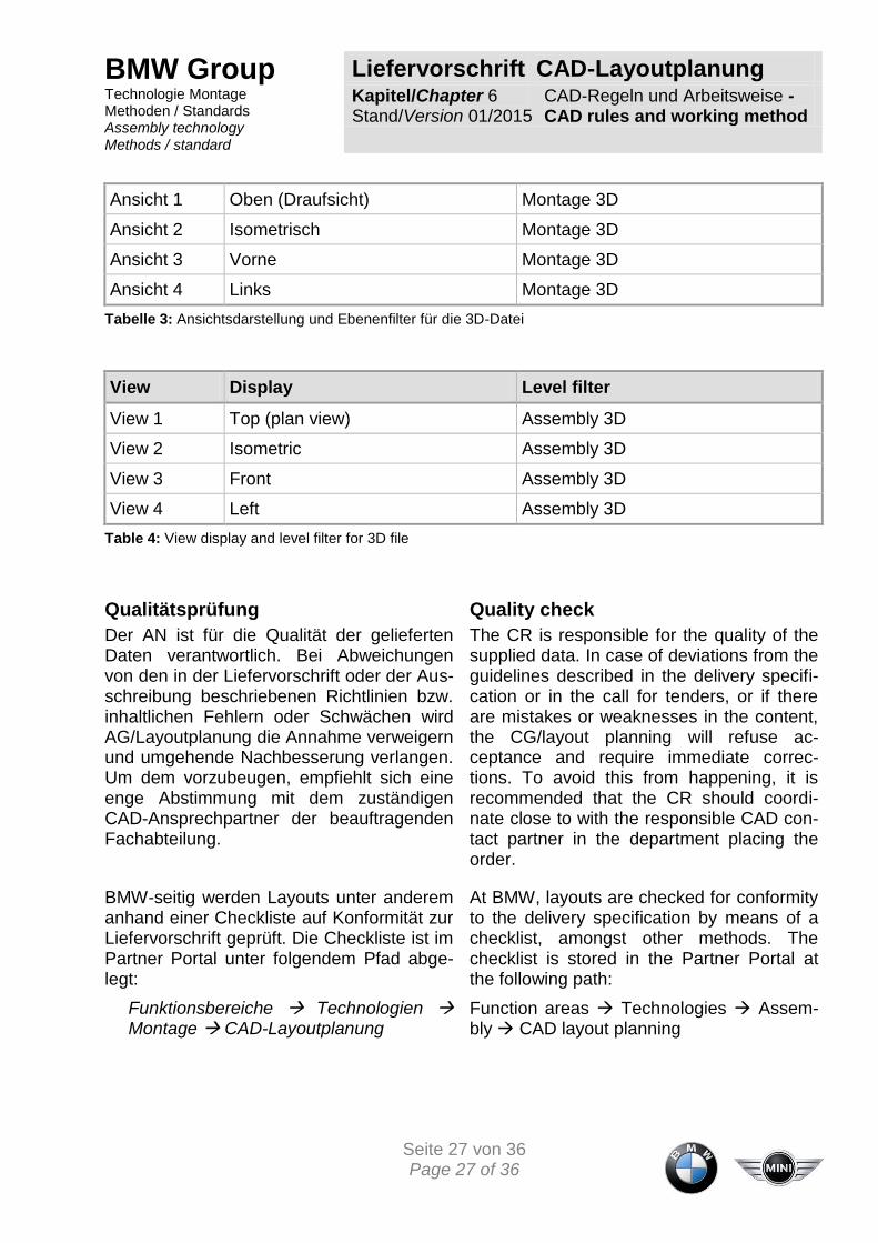
Ansicht 1 Oben (Draufsicht) Montage 3D
Ansicht 2 Isometrisch Montage 3D
Ansicht 3 Vorne Montage 3D
Ansicht 4 Links Montage 3D
Tabelle 3: Ansichtsdarstellung und Ebenenfilter für die 3D-Datei
View Display Level filter
View 1 Top (plan view) Assembly 3D
View 2 Isometric Assembly 3D
View 3 Front Assembly 3D
View 4 Left Assembly 3D
Table 4: View display and level filter for 3D file
Qualitätsprüfung
Der AN ist für die Qualität der gelieferten Daten verantwortlich. Bei Abweichungen von den in der Liefervorschrift oder der Aus-schreibung beschriebenen Richtlinien bzw. inhaltlichen Fehlern oder Schwächen wird AG/Layoutplanung die Annahme verweigern und umgehende Nachbesserung verlangen. Um dem vorzubeugen, empfiehlt sich eine enge Abstimmung mit dem zuständigen CAD-Ansprechpartner der beauftragenden Fachabteilung.
BMW-seitig werden Layouts unter anderem anhand einer Checkliste auf Konformität zur Liefervorschrift geprüft. Die Checkliste ist im Partner Portal unter folgendem Pfad abge-legt:
Quality check
The CR is responsible for the quality of the supplied data. In case of deviations from the guidelines described in the delivery specifi-cation or in the call for tenders, or if there are mistakes or weaknesses in the content, the CG/layout planning will refuse ac-ceptance and require immediate correc-tions. To avoid this from happening, it is recommended that the CR should coordi-nate close to with the responsible CAD con-tact partner in the department placing the order.
At BMW, layouts are checked for conformity to the delivery specification by means of a checklist, amongst other methods. The checklist is stored in the Partner Portal at the following path:
Funktionsbereiche Technologien Montage CAD-Layoutplanung
Function areas Technologies Assem-bly CAD layout planning

BMW Group Liefervorschrift CAD-Layoutplanung Technologie Montage Methoden / Standards Assembly technology Methods / standard
Kapitel/Chapter 7 Stand/Version 01/2015
Detaillierungsgrad - Level of detail
Seite 28 von 36 Page 28 of 36
7 Detaillierungsgrad - Level of detail
CAD-Objekte müssen in der Layoutplanung im richtigen (angemessenen) Detaillie-rungsgrad modelliert werden. Ein zu hoher Detaillierungsgrad führt zu hohen Aufwän-den bei der CAD-Modellierung und späteren Handhabung (Visualisieren, Plotten etc.). Vor diesem Hintergrund werden in der CAD-Layoutplanung grundsätzlich keine Normtei-le dargestellt.
CAD objects shall be modelled with the right (appropriate) level of detail in the layout planning. An excessively high level of detail results in high complexity during CAD mod-elling and subsequent handling (visualisa-tion, plotting, etc.). In view of this, no stan-dard parts are to be displayed in the CAD layout planning.
Im Gegensatz dazu können bei einem zu niedrigen Detaillierungsgrad die Vorteile der 3D-Planung nicht ausgeschöpft werden, da die Aussagekraft der CAD-Modelle verloren geht.
On the other hand, if the level of detail is too little then the advantages of the 3D planning cannot be utilised to its full, and some value of the CAD models is lost.
7.1 Detaillierung im Planungsprozess - Detailing in the planning pro-cess
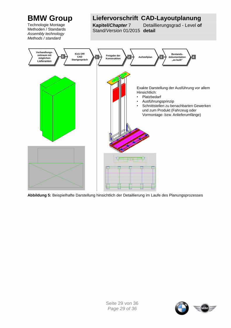
Grundsätzlich stellen die Layouts zu jeder Projektphase den Reifegrad der aktuellen Planung dar. Zum Projektstart kann es bei-spielsweise hilfreich sein, eine Prozessan-lage im Sinne einer Bauraumreservierung als Block darzustellen, um den zu erwarten-den Platzbedarf auszudrücken.
Generally the layouts for each project phase represent the degree of maturity of the planning. At the project start it can for ex-ample be helpful to represent the system layout as a block in order to reserve floor space, to indicate the expected amount of space required.
BMW Group Liefervorschrift CAD-Layoutplanung Technologie Montage Methoden / Standards Assembly technology Methods / standard
Kapitel/Chapter 7 Stand/Version 01/2015
Detaillierungsgrad - Level of detail
Seite 29 von 36 Page 29 of 36
Exakte Darstellung der Ausführung vor allem
Hinsichtlich:
• Platzbedarf
• Ausführungsprinzip
• Schnittstellen zu benachbarten Gewerken
und zum Produkt (Fahrzeug oder
Vormontage- bzw. Anlieferumfänge)
Freigabe der
KonstruktionAufstellplan
Bestands-
dokumentation
„as built“1 2 3 4
Verhandlungs-
zeitraum mit
möglichen
Lieferanten
Kick Off/
CAD
Startgespräch0
Abbildung 5: Beispielhafte Darstellung hinsichtlich der Detaillierung im Laufe des Planungsprozesses

BMW Group Liefervorschrift CAD-Layoutplanung Technologie Montage Methoden / Standards Assembly technology Methods / standard
Kapitel/Chapter 7 Stand/Version 01/2015
Detaillierungsgrad - Level of detail
Seite 30 von 36 Page 30 of 36
Exact representation of the configuration
above all with regard to:
• space requirement
• configuration principle
• interfaces to the adjacent Technologies
and to the product (vehicle or sub
assembly - meaning scope of delivery)
Release of the
constructionFloor plan
“As built“
documentation1 2 3 4
Negotiation
time frame with
possible
suppliers
Kick Off/CAS
Opening
discussion0
Figure 5: Example presentation with the view on detailing during the planning process
Die Verwendung von (detaillierten) Biblio-thekselementen oder Vorgänger-Konstruktionen in der frühen Planungspha-se, die nicht das spätere Ausführungsprinzip darstellen, sind nicht zulässig, da sie auf-grund falscher Darstellung bzw. Detaillie-rung zu Fehlplanungen bzw. zu Fehlein-schätzungen führen.
It is not permitted to use (detailed) library elements or previous designs in the early planning phase that do not represent the final configuration principle. This is because they might result in planning errors or incor-rect estimations by the incorrect representa-tion in other words detailing.
Die Darstellung von Konstruktionsdetails, wie z.B. Normteile (Schrauben, Muttern, etc.), kleine Phasen und Verrundungen und Verbindungselemente, die keinen Mehrwert im Rahmen der Layoutplanung darstellen, ist nicht gestattet, da dadurch die Daten-menge unnötig ansteigt und somit die Handhabung erschwert wird.
It is not permitted for design details such as standard parts (bolts, nuts, etc.), small chamfers, rounding’s and connecting ele-ments to be shown which do not provide any added value as part of layout planning. This is because by doing so, the data quan-tity is increased unnecessarily, and thus the handling is made more complicated.
BMW Group Liefervorschrift CAD-Layoutplanung Technologie Montage Methoden / Standards Assembly technology Methods / standard
Kapitel/Chapter 7 Stand/Version 01/2015
Detaillierungsgrad - Level of detail
Seite 31 von 36 Page 31 of 36
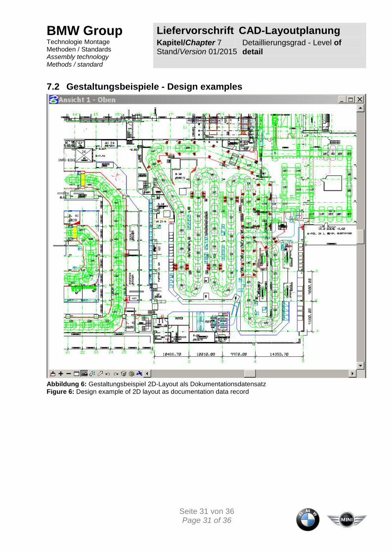
7.2 Gestaltungsbeispiele - Design examples
Abbildung 6: Gestaltungsbeispiel 2D-Layout als Dokumentationsdatensatz Figure 6: Design example of 2D layout as documentation data record

BMW Group Liefervorschrift CAD-Layoutplanung Technologie Montage Methoden / Standards Assembly technology Methods / standard
Kapitel/Chapter 7 Stand/Version 01/2015
Detaillierungsgrad - Level of detail
Seite 32 von 36 Page 32 of 36
Abbildung 7: 3D-Gestaltungsbeispiel Dokumentationsdatensatz Heber Figure 7: 3D design example of documentation data record lifter
BMW Group Liefervorschrift CAD-Layoutplanung Technologie Montage Methoden / Standards Assembly technology Methods / standard
Kapitel/Chapter 7 Stand/Version 01/2015
Detaillierungsgrad - Level of detail
Seite 33 von 36 Page 33 of 36
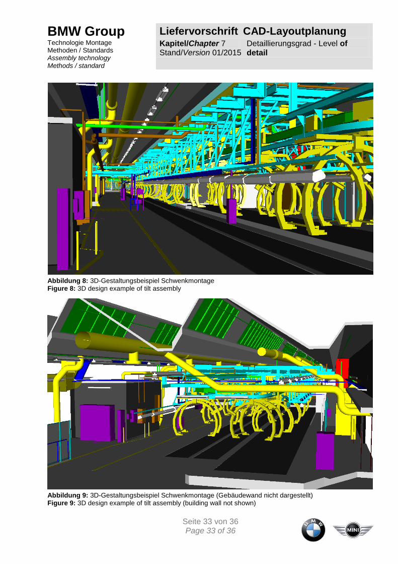
Abbildung 8: 3D-Gestaltungsbeispiel Schwenkmontage Figure 8: 3D design example of tilt assembly
Abbildung 9: 3D-Gestaltungsbeispiel Schwenkmontage (Gebäudewand nicht dargestellt) Figure 9: 3D design example of tilt assembly (building wall not shown)

BMW Group Liefervorschrift CAD-Layoutplanung Technologie Montage Methoden / Standards Assembly technology Methods / standard
Kapitel/Chapter 7 Stand/Version 01/2015
Detaillierungsgrad - Level of detail
Seite 34 von 36 Page 34 of 36
Abbildung 10: 3D-Gestaltungsbeispiel Schwenkmontage Figure 10: 3D design example of tilt assembly

BMW Group Liefervorschrift CAD-Layoutplanung Technologie Montage Methoden / Standards Assembly technology Methods / standard
Kapitel/Chapter 7 Stand/Version 01/2015
Detaillierungsgrad - Level of detail
Seite 35 von 36 Page 35 of 36
Abbildung 11: 3D-Gestaltungsbeispiel Detaillierungsgrad Schwenkgehänge für Layoutplanung Figure 11: 3D- Design example of degree of detail in a tilt hanger for layout planning
BMW Group Liefervorschrift CAD-Layoutplanung Technologie Montage Methoden / Standards Assembly technology Methods / standard
Kapitel/Chapter 7 Stand/Version 01/2015
Detaillierungsgrad - Level of detail
Seite 36 von 36 Page 36 of 36
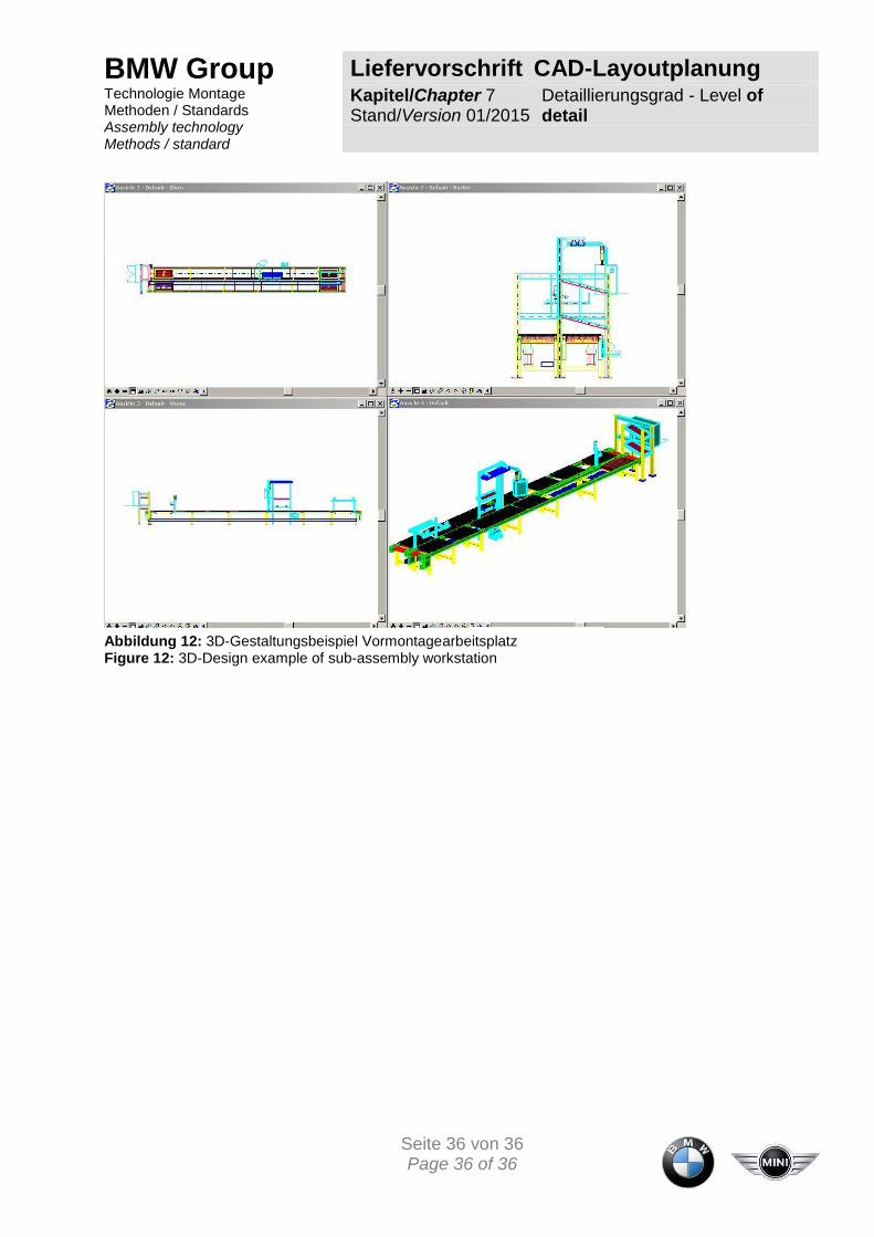
Abbildung 12: 3D-Gestaltungsbeispiel Vormontagearbeitsplatz Figure 12: 3D-Design example of sub-assembly workstation