Deliverable D4.4.1 Initial Modelling of the ENG Case...
32
Deliverable D4.4.1 Initial Modelling of the ENG Case Study Date of document: T10 (resubmitted T14) Final version Project N o : FP7-610582 Project Acronym: ENVISAGE Project Title: Engineering Virtualized Services Instrument: Collaborative Project Scheme: Information & Communication Technologies Start date of the project: 1 st October 2013 Duration: 36 months Organisation name of lead contractor for this deliverable: ENG STREP Project supported by the 7th Framework Programme of the EC Dissemination Level PU Public ✓ PP Restricted to other programme participants (including Commission Services) RE Restricted to a group specified by the consortium (including Commission Services) CO Confidential, only for members of the consortium (including Commission Services)
Transcript of Deliverable D4.4.1 Initial Modelling of the ENG Case...
���
Deliverable D4.4.1Initial Modelling of the ENG Case Study
Date of document: T10 (resubmitted T14)
���
Final version
Project No: FP7-610582
Project Acronym: ENVISAGE
Project Title: Engineering Virtualized Services
Instrument: Collaborative Project
Scheme: Information & Communication Technologies
Start date of the project: 1st October 2013
Duration: 36 months
Organisation name of lead contractor for this deliverable: ENG
STREP Project supported by the 7th Framework Programme of the EC
Dissemination Level
PU Public ✓
PP Restricted to other programme participants (including Commission Services)
RE Restricted to a group specified by the consortium (including Commission Services)
CO Confidential, only for members of the consortium (including Commission Services)

Executive Summary:Initial Modelling of the ENG Case Study
This document summarises deliverable D4.4.1 of project FP7-610582 (Envisage), a Collaborative Project supported by the 7th Framework Programme of the EC within the Information & Communication Technologies scheme. Full information on this project is available online at http://www.envisage-project.eu.
This deliverable reports on the initial modelling of the structural and functional aspects of the ENG case study, and details how the case study plans to cover the objectives O1-O6 of Envisage. This deliverable forms a part of the verification of Envisage project milestone M1.
List of AuthorsKeven T. Kearney (ENG)

Contents
1. Introduction 1 1.1. Overview of the ENG Case Study 1
1.1.1. The ETICS Service 2 1.1.2. Objective of the Case Study 3
2. RPM System Requirements 3 2.1. Execution Context 4 2.2. ETICS Quality of Service (QoS) 5
2.2.1. Consumer Facing SLAs 5 2.2.2. Provider Facing SLAs 6
2.3. Functional Requirements for the RPM 6 2.3.1. UML Use Cases 7 2.3.2. Regulatory Behaviour of the RPM 8
2.4. ETICS Components 11 2.4.1. Resource Pool 11 2.4.2. Request Queue 12 2.4.3. Execution Engine 13 2.4.4. Resource Factory 14 2.4.5. User Database 14
2.5. Resource Pool Manager (RPM) 15 2.6. Simulator 15
2.6.1. User Model 16
3. Implementation 17 3.1. Simulator 18 3.2. Resources 19 3.3. Functional (non-procedural) Definitions 20 3.4. Execution Engine 21 3.5. RPM 23 3.6. Initial Comments 25
4. Relevance To Project Goals 26 4.1. Relation to Envisage Objectives & Milestones 26 4.2. Summary 28
Bibliography 29

1. Introduction
This document constitutes deliverable D4.4.1, “Initial Modelling of the ENG Case Study”, of the FP7-ICT-2013 Project Envisage (Engineering Virtualised Services), and presents an initial, formal model of the structural and functional aspects of the Engineering case study. The objective of the case study is to employ the Envisage methodology (comprising the ABS language, its associated tools & workflow) to develop an automated ‘Resource Pool Manager’ component for the elastic management of the computational resources utilised by ENG’s ETICS service.
1.1. Overview of the ENG Case Study
The ENG case study concerns the development of ETICS (E-Infrastructure for Testing, Integration and Configuration of Software), a web-based service for the execution and quality assurance of builds and tests for distributed, multi-language, multi-platform software. ETICS was originally developed within the European Research Projects ETICS and ETICS2 , and is currently being 1 2
extended and improved by Engineering’s Research & Development department. At the moment, the service is used internally by Engineering’s Software Lab, and is hosted on a private cloud (virtual infrastructure) maintained by Engineering’s Managed Operations (MO) division. For the future, the objective is to offer ETICS as a commercial service - which minimally requires:
• moving from a private to a hybrid virtual infrastructure (incorporating public clouds such as Amazon AWS , Microsoft Azure , Google Cloud ) - to handle the case that demand exceeds the 3 4 5
capacities of Engineering MO; and• employing reliable mechanisms to dynamically scale/reorganise the infrastructure to maintain
cost-effectiveness in the face of fluctuations in demand.Within this commercial context, SLAs will govern both the use of ETICS by developers (consumer
facing SLAs), as well as Engineering’s use of third party clouds (provider facing SLAs). Figure 1.1-a summaries the overall scenario.
!Figure 1.1-a: Commercial Scenario for ETICS
The following subsections briefly describe the ETICS service, and the objectives of the case study.
ETICS Service
Developer
usesHybrid Cloudexecutes on
Private Cloud
Public Cloud
Public Cloud …
ENG Third Party Cloud Provider
SLASLA
provides
provides e.g.Amazon AWSMicrosoft AzureGoogle Cloud…(consumer facing) (provider facing)
ETICS (FP6 European Research Project): http://project-eu-etics1.web.cern.ch/project-eu-etics1/index.html 1
ETICS2 (FP7 European Research Project): http://etics-archive.web.cern.ch/etics-archive/ 2
Amazon AWS: https://aws.amazon.com 3
Microsoft Azure: http://azure.microsoft.com/en-gb/ 4
Google Cloud: https://cloud.google.com 5
!1
1.1.1. The ETICS Service
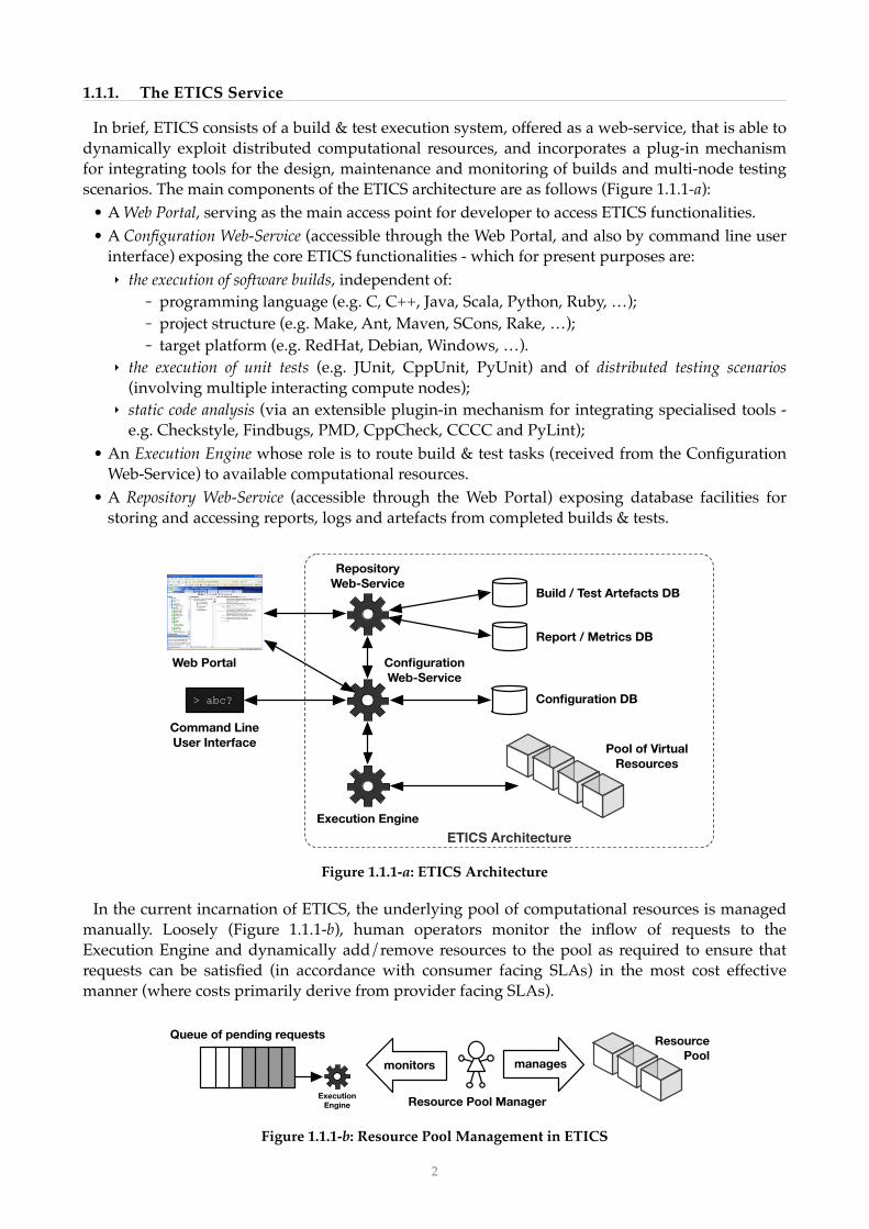
In brief, ETICS consists of a build & test execution system, offered as a web-service, that is able to dynamically exploit distributed computational resources, and incorporates a plug-in mechanism for integrating tools for the design, maintenance and monitoring of builds and multi-node testing scenarios. The main components of the ETICS architecture are as follows (Figure 1.1.1-a):
• A Web Portal, serving as the main access point for developer to access ETICS functionalities.• A Configuration Web-Service (accessible through the Web Portal, and also by command line user
interface) exposing the core ETICS functionalities - which for present purposes are:‣ the execution of software builds, independent of:
- programming language (e.g. C, C++, Java, Scala, Python, Ruby, …);- project structure (e.g. Make, Ant, Maven, SCons, Rake, …);- target platform (e.g. RedHat, Debian, Windows, …).
‣ the execution of unit tests (e.g. JUnit, CppUnit, PyUnit) and of distributed testing scenarios (involving multiple interacting compute nodes);
‣ static code analysis (via an extensible plugin-in mechanism for integrating specialised tools - e.g. Checkstyle, Findbugs, PMD, CppCheck, CCCC and PyLint);
• An Execution Engine whose role is to route build & test tasks (received from the Configuration Web-Service) to available computational resources.
• A Repository Web-Service (accessible through the Web Portal) exposing database facilities for storing and accessing reports, logs and artefacts from completed builds & tests.
!Figure 1.1.1-a: ETICS Architecture
In the current incarnation of ETICS, the underlying pool of computational resources is managed manually. Loosely (Figure 1.1.1-b), human operators monitor the inflow of requests to the Execution Engine and dynamically add/remove resources to the pool as required to ensure that requests can be satisfied (in accordance with consumer facing SLAs) in the most cost effective manner (where costs primarily derive from provider facing SLAs).
!Figure 1.1.1-b: Resource Pool Management in ETICS
ETICS Architecture
RepositoryWeb-Service
ConfigurationWeb-Service
> abc?
Build / Test Artefacts DB
Report / Metrics DB
Configuration DB
Web Portal
Command LineUser Interface
Execution Engine
Pool of VirtualResources
Queue of pending requests
ExecutionEngine
ResourcePool
Resource Pool Manager
managesmonitors
!2

1.1.2. Objective of the Case Study
The ENG case study focuses on the Resource Pool Manager introduced in the previous section. Specifically, the objective of the case study is to employ the Envisage methodology to develop an automated ‘Resource Pool Manager’ (henceforth RPM) for the elastic management of the ETICS computational resource pool. This objective can be taken as an extended and elaborated version of Usage Scenario 1 presented in the DOW (Part B, page 8, Figure 7).
Some notes are in order to clarify the objective:• The RPM will be implemented as an ABS model, and the Envisage analysis and simulation
tools will be used primarily to determine the characteristics of (and to tune) this model.• As a critical component of the overall ETICS service, the non-functional properties of the RPM
are constrained by the same consumer-facing SLAs that govern the service as a whole, e.g.‣ if the SLA specifies an availability, α, for the ETICS service, then since the service depends on
the RPM, the RPM must also obtain an availability equal to or greater than α;‣ if the SLA specifies a maximum completion-time for end-user requests to the ETICS service,
then the RPM must be able to ensure that computational resources are available (in the pool) to execute requests in a timely fashion (such that requests can be completed within the given time limit).
• The RPM will use a distributed algorithm, and will dynamically (elastically) scale the quantity of its own internal concurrent processes as the number of active requests change.‣ The reason for a distributed approach is that, while the computational burden on the RPM
can be expected to increase with the number of end-user requests and resources, the time taken for the RPM to compute resource requirements should be more-or-less constant (assuming time constraints on request processing as noted above).
• The RPM is intended as a proof of concept prototype: it is not required to be of production quality (ready for deployment within the operational ETICS system). Specifically, the RPM:‣ will be implemented/executed within a mock-up of the wider ETICS architecture: using
dummy components to mimic internal service interactions; and‣ will be tested within an idealised simulation environment using probabilistic models of end
user behaviour, rather than in a live setting (with actual end-users making actual requests) . 6
Both the mock-up components & simulation environment will also be implemented in ABS. • The Envisage methodology only applies to the development of the RPM and associated ETICS
mock-up & simulation environment. In particular, it should be noted that the build and test processes executed by ETICS are 3rd party proprietary tools (e.g. compilers), which will not be modelled in ABS, and are thus not amenable to analysis by Envisage tools.
The system requirements for the RPM are defined in the next section.
2. RPM System Requirements
This section specifies requirements for the implementation of the RPM, and is divided into the following subsections:
2.1 Execution Context: clarifying the relation of the RPM to the elements of the ETICS service.2.2 Quality of Service (QoS): specifying relevant non-functional constraints from consumer and
provider facing SLAs.
The simulation environment implemented in this case study should not be confused with the simulation tools provided 6
by Envisage. The purpose of the simulation environment is to test the reliability of the Envisage tools in predicting the characteristics of the RPM.
!3
2.3 Functional Requirements - in the form of UML Use Cases describing the external relations of the RPM, and an overview of the problem space (governing the RPM’s internal calculations).
2.4 ETICS Components: UML class diagrams for the mock-up ETICS components. 2.5 Resource Pool Manager (RPM): UML class diagram for the RPM.2.6 Simulator: UML class diagram for the simulation environment (for testing the RPM).
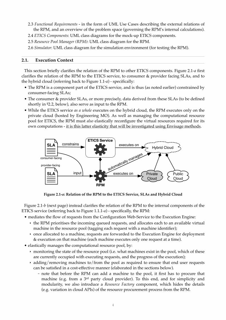
2.1. Execution Context
This section briefly clarifies the relation of the RPM to other ETICS components. Figure 2.1-a first clarifies the relation of the RPM to the ETICS service, to consumer & provider facing SLAs, and to the hybrid cloud (referring back to Figure 1.1-a) - specifically:
• The RPM is a component part of the ETICS service, and is thus (as noted earlier) constrained by consumer-facing SLAs;
• The consumer & provider SLAs, or more precisely, data derived from these SLAs (to be defined shortly in §2.2, below), also serve as input to the RPM.
• While the ETICS service as a whole executes on the hybrid cloud, the RPM executes only on the private cloud (hosted by Engineering MO). As well as managing the computational resource pool for ETICS, the RPM must also elastically reconfigure the virtual resources required for its own computations - it is this latter elasticity that will be investigated using Envisage methods.
!Figure 2.1-a: Relation of the RPM to the ETICS Service, SLAs and Hybrid Cloud
Figure 2.1-b (next page) instead clarifies the relation of the RPM to the internal components of the ETICS service (referring back to Figure 1.1.1-a) - specifically, the RPM:
• mediates the flow of requests from the Configuration Web-Service to the Execution Engine:‣ the RPM prioritises the incoming queued requests, and allocates each to an available virtual
machine in the resource pool (tagging each request with a machine identifier);‣ once allocated to a machine, requests are forwarded to the Execution Engine for deployment
& execution on that machine (each machine executes only one request at a time).• elastically manages the computational resource pool, by:
‣ monitoring the state of the resource pool (i.e. what machines exist in the pool, which of these are currently occupied with executing requests, and the progress of the execution);
‣ adding/removing machines to/from the pool as required to ensure that end user requests can be satisfied in a cost-effective manner (elaborated in the sections below).- note that before the RPM can add a machine to the pool, it first has to procure that
machine (e.g. from a 3rd party cloud provider). To this end, and for simplicity and modularity, we also introduce a Resource Factory component, which hides the details (e.g. variation in cloud APIs) of the resource procurement process from the RPM.
ETICS ServiceHybrid Cloud
executes on
Private Cloud
Public Cloud
SLA
RPM
executes oninputautomatically manages
consumer-facing
SLA constrains
provider-facing
!4

In short, the basic task of the RPM is to regulate (by observing and modifying) the states of both the request queue and resource pool in order to ensure (as far as possible) that the ETICS service operates at a profit.
!Figure 2.1-b: Interaction of the RPM with ETICS
2.2. ETICS Quality of Service (QoS)
As already noted (§1.1.2 & §2.1), both the functional and non-functional properties of the RPM are governed by quality-of-service (QoS) constraints defined in consumer- and provider-facing SLAs. The QoS constraints particularly relevant to the RPM are defined in the following two sections (note that this list is not an exhaustive account of the QoS terms defined in the SLAs). How these QoS constraints affect the RPM is explained shortly in §2.3.2.
2.2.1. Consumer Facing SLAs
Consumer facing SLAs govern the use of the ETICS service by end users (software developers). The following information derived from these SLAs is relevant to the RPM:
• request-cost: the cost (in €) per unit request-size, and dependent on request-priority, of using the ETICS service, where:‣ request-size is a measure of the computational load engendered by a request - calculated as
a fixed function of the task type (e.g. ANT build, JUnit test, etc.), task configuration (e.g. dependencies) and the quantity of source code over which the task operates;
‣ request-priority is a Boolean value indicating whether the request is:- scheduled (low priority & lower cost), e.g. as part of a regular (nightly) automated batch
build process; or- ad-hoc (high priority & higher cost), received directly from the end user;
‣ end users only pay for successful requests (failed requests are penalised - see below).7
• maximum completion-time (ctmax): an upper-bound, specified as a function of request-size and request-priority, on the completion-time, ct = tout − tin, of requests - where:‣ tin is the time at which the request is received;‣ tout (> tin) is the time at which execution of the request ‘successfully’ completes;
Execution EngineRPM
Queue of pending requests
Pool of VirtualResources
ConfigurationWeb-Service
End-user requests
Queue of pending requests
add/remove resources
A B C AB
C
elastic resource management
Resource Factory
Private Cloud
Public Cloud
Public Cloud
…
monitor state
“Success” means that the task was executed, and was not prematurely halted by (either intentionally or due to a failure 7
of) the ETICS system:• in particular note that the executed task per se may result in an exception (e.g. due to run-time 3rd party compiler
errors), but still be ‘successful’ from the point of view of the ETICS system;• the end user receives a notification that the task is complete, including links/references to the resulting artefacts &
reports (which can be accessed through the Repository Web-Service).
!5

‣ note that both tin and tout are measured server-side, i.e. network latency (for communications between the end user and the ETICS server) is not taken into account.
‣ Ad-hoc requests have shorter maximum completion-times than scheduled requests;• completion-time penalty: the penalty (a refund, in €, paid to the end user) for failing to satisfy
the maximum completion-time guarantee - calculated for each request as kct(ct − ctmax), where kct is a constant (larger for ad-hoc requests) and the penalty only applies to tasks that successfully complete and is thus 0 for ct ≤ ctmax.
• maximum failure rate (frmax): an upper-bound on the request failure-rate, fr = m/n, where:‣ n is the total number of valid requests (both ad-hoc & scheduled) received in a standard time 8
period (e.g. ‘daily’); and‣ m (≤ n) is the number of these requests that failed to ‘successfully’ complete.
• failure-rate penalty: the penalty (user refund, in €) for failing to satisfy the maximum failure-rate bound - calculated (for each standard time period) as kfr(fr − frmax), where kfr is a constant, and the penalty is 0 for fr ≤ frmax.
2.2.2. Provider Facing SLAs
Provider facing SLAs govern the use, by the ETICS system, of cloud provisioning services (e.g. Engineering MO, Amazon AWS, etc.). The following information derived from these SLAs is relevant to the RPM:
• resource-cost: the cost (in €) w.r.t. cost-time-unit of using (deploying) a given resource, where:‣ The total cost, c’, of using a resource is calculated as c’ = c × ⎡T/t⎤ × t, where:
- c is the resource-cost; - T is the total time the resource was used (deployed);- t is the cost-time-unit (a duration, e.g. 1 hour);- ⎡x⎤ is the ceiling of (= the smallest integer not less than) x.
• maximum deploy-time (dtmax): an upper-bound on the time, dt = tout − tin, required to provision and deploy a resource, where:‣ tin is the time at which the request to deploy a resource is received by the cloud provider;‣ tout is the time at which the requested resource is available for use by the ETICS system.
• deploy-time penalty: the penalty (a refund, in €, from the cloud provider) for failing to satisfy the maximum deploy-time bound - calculated for each deployed resource as kdt(dt − dtmax), where kdt is a constant and the penalty is 0 for dt ≤ dtmax.
2.3. Functional Requirements for the RPM
This section describes the basic functional properties of the RPM, and is divided into 2 sections: • §2.3.1 UML Use Cases: provides a high-level description of the input/output relations between
the RPM and other ETICS components - i.e. the information it receives, and actions it can take; • §2.3.2 Regulatory Behaviour of the RPM: describes the high-level function (goal) of the RPM, and
outlines the basic nature of its decision making processes.
A request is ‘valid’ if:8
• the request content is well-formed syntactically, and contains all required information;• the request comes from an authenticated and valid user - in particular, that there exists an active (consumer facing)
SLA governing the user’s use of the ETICS service;• the user is permitted to make the request, both with respect to:
- any security constraints, e.g. appropriate permissions for accessing shared content, and- the terms of the governing SLA, e.g. the user has not exceeded usage limits.
!6

2.3.1. UML Use Cases
The manifest behaviour of the RPM is captured by the UML use case diagram shown in Figure 2.3.1-a. The individual use cases are described in the dedicated subsections below.
!Figure 2.3.1-a: UML Use Cases for the RPM
2.3.1.1. Use Case: Monitor Request Queue
As stated earlier, the basic task of the RPM is to monitor the inflow of requests and to manage the resource pool to ensure that requests can be satisfied in accordance with consumer facing SLAs. The queue itself is essentially a list of build/test requests, and the RPM just needs to be informed of changes (additions/removals) to this list.
We assume that the queue only contains valid8 requests, and that each request has also been pre-processed and elaborated (in some way) with the following information (required by the RPM - refer back to §2.2.1):
• user identifier: required to access (data derived from) the user’s request history (for determining failure-rates) and SLA (for user-specific QoS parameters);
• time at which the request was received; • request-size: a measure of the computational load engendered by the request; • request-priority: i.e. scheduled vs ad-hoc;• minimal resource requirements: the minimal machine configuration necessary for executing the
requested build/test task - e.g. CPU architecture, operating system, pre-installed software, and lower bounds on memory & disk space.
2.3.1.2. Use Case: Reject Request
If the RPM determines that a request cannot be satisfied, or that the cost of satisfying a request is greater than the benefit, then it can reject the request: removing it from the queue, and potentially incurring a penalty for failed requests (§2.2.1). Otherwise all requests are accepted.
2.3.1.3. Use Case: Monitor Resource Pool
As well as monitoring the state of the request queue (above), the RPM also monitors the state of the computational resource pool. Specifically, the RPM needs to be informed:
• about which machines are currently in the pool;• which are currently occupied with executing a request;• what is the progress of the execution, i.e. how long until it completes.
2.3.1.4. Use Case: Search Resource Catalogue
The resource catalogue is essentially the list of different resource types/configurations available from the Resource Factory. The RPM accesses this catalogue (indirectly) by querying the Resource Factory for a list of resources satisfying particular constraints - e.g. maximum cost, required CPU architecture, minimum CPU speed, maximum deploy-time, etc.
RPM
Monitor Request Queue
Reject Request
Monitor Resource PoolAssign Resource to Request
Decommission Resource
Commission Resource
Search Resource Catalogue
!7

2.3.1.5. Use Case: Commission Resource
Once the RPM has located a suitable resource in the resource catalogue (above), it can request the Resource Factory to procure and deploy the resource on the hybrid cloud (Figure 1.1-a) - which is equivalent to adding the resource to the resource pool. The procurement/deployment process may take several minutes to complete.
• Note that the resource provider pays a penalty if the resource is not deployed within the maximum deploy-time stipulated in the provider facing SLAs (§2.2.2).
2.3.1.6. Use Case: Assign Resource to Request
The RPM assigns specific resources to specific requests (tagging each request with the identifier of its assigned resource). Once assigned, the request is removed from the incoming queue, and forwarded to the Execution Engine, which if necessary, waits (up to some time-out limit) for the assigned resource to become free, and then triggers the execution of the requested task on that resource. If the resource is still occupied after the time-out, the request fails.
• Once a request has been posted to the Execution Engine its resource assignment is fixed, and can no longer be changed by the RPM;
• Before the task proper can be executed, the Execution Engine first copies source files (and any other data required for the task) to the resource for local access, which may take up to several minutes depending on the request-size;
• Likewise, once the execution is complete, these local input files are deleted, and the artefacts/reports generated by the task are transferred to the ETICS repository, which also takes time;
Note that the RPM can control/influence the timing of task execution by: • delaying the assignment of a resource to the request; • delaying posting the request to the Execution Engine; • assigning a resource that is currently occupied with another request.
2.3.1.7. Use Case: Decommission Resource
If the RPM determines that a resource is no longer required, it can request the Resource Factory to decommission that resource - which is equivalent to removing the resource from the resource pool. Resources can be decommissioned at any time - with the caveat that a request will fail if its assigned resource is removed before it has completed execution of the request.
2.3.2. Regulatory Behaviour of the RPM
The basic objective of the RPM is to manage the computational resource pool and the assignment of end-user requests to available resources, in such a way as to (attempt to) maximise profit, which we define as follows (refer back to the definitions in §2.2):
• profitT = (requestsT + refundsT) − (resourcesT + penaltiesT), where T is an arbitrary duration over which the following values (in €) are calculated: ‣ requestsT = the total income from end user requests, i.e. ∑0 ≤ i ≤ n cisi where n is the number of
successful requests, ci the request-cost, and si the request-size (§2.2.1) of the ith request;‣ refundsT = the total in penalties paid by cloud providers (to ENG as the cloud consumer) due
to violations of deploy-time guarantees (§2.2.2);‣ resourcesT = the total cost of computational resources, i.e. ∑0 ≤ i ≤ n c’i where n is the total
number of resources used, and c’ is the total cost (§2.2.2) of the ith resource;‣ penaltiesT = the total in penalties paid to end users due to violation of completion-time &
failure-rate guarantees (§2.2.1);
!8

• note that neither requestsT nor refundsT fall under the direct control of the RPM (since they depend on the activities of end users and cloud providers resp.), hence ‘maximising profit’ primarily entails minimising resourcesT (using as few resources as possible), and minimising penaltiesT (ensuring as many requests are satisfied, on time, as possible).
The regulatory behaviour of the RPM can then be illustrated by the following concrete example: • Suppose that a consumer facing SLA specifies that, for a request, r, of a certain size & priority:
‣ the consumer must pay €5;‣ the provider (ENG):
- guarantees a maximum completion-time, ctmax, of 10 minutes (as measured from the time of receipt, tin, of the request);
- must pay a penalty of €1/minute for completion-times over ctmax.• Ignoring other cost factors, Figure 2.3.2-a then shows how the profit to the provider varies with
the actual completion-time, ct, of r (negative profit corresponds to the payment of penalties).
!Figure 2.3.2-a: Plot of Profit vs Completion-Time
• Now suppose that for a given machine configuration, m, the execution-time, δ, for request r is 5 minutes, then if tstart is the time at which the execution of r begins, and Q = tin + ctmax:‣ tin < tstart < Q − δ brings in a profit of €5 (Figure 2.3.2-b: ‘window for maximum profit’);‣ Q − δ < tstart < Q brings in a steadily diminishing profit (Figure 2.3.2-b: ‘window for less than
maximum profit’); while‣ Q < tstart results in steadily increasing loss.
• Accordingly, if no machine (m) is available at tin to execute r, then in order to make at least some profit, the RPM must add such a machine to the pool before Q (and preferably before Q − δ).‣ More precisely: the RPM needs to find a machine (m) with maximum deploy-time, dtmax < ctmax
− ∆, where ∆ is the additional time it takes the RPM to search for & request the deployment of m, and for the Execution Engine to then setup m for executing r (e.g. copying files etc.).
!Figure 2.3.2-b: Execution-Time of 5 mins
profi
t (€) ct
0
5
−5
ctmax10 mins 10 mins
profi
t (€) ct
0
5
−5
ctmax10 mins 10 mins
window formaximum profit
window for less than maximum profit
δδ
δ = execution time(Q)
!9

• Even if it is not possible to make a profit, however, it may still be worth attempting to satisfy the request. In particular: ‣ if no machine (m) can be deployed in time to execute r at a profit,‣ but rejecting r would result in exceeding the maximum failure-rate , frmax,‣ then the RPM needs only to ensure that the penalty, pct, paid for exceeding the maximum
completion-time on r (in the case that r is executed) is less than the penalty, pfr, paid for exceeding the maximum failure-rate (in the case that r is rejected);
‣ In short: the RPM needs to find a machine (m) with a maximum deploy-time, dtmax < T − δ, where T (> ctmax) is the time (from tin) at which pct = pfr, as illustrated in Figure 2.3.2-c;- Or again, to be precise: dtmax < T − δ − ∆ (see previous bullet).
‣ Indeed, this ‘loss cutting’ constraint is the general case, and applies to all requests.
!Figure 2.3.2-c: Balancing Completion-Time & Failure-Rate Constraints
• To further complicate matters, however, we also need to account for the fact that machines: ‣ have a cost, which must be subtracted from the ‘raw’ profit above;‣ run at different speeds, where a faster machine will:
- execute requests more quickly, allowing the execution to be delayed longer; but also …- cost more, thus reducing both the profit, and the time that the execution can be delayed.
To illustrate, Figure 2.3.2-d compares two profit graphs: i) for a slow/cheap machine, and ii) for a fast/expensive machine. ‣ For simplicity the machine cost is approximated as a constant in Figure 2.3.2-d (the dash-dot
line), but will instead increase step-wise with time (cf. the total-cost formula given in §2.2.2).
!Figure 2.3.2-d: Machine Cost & Speed
i) on a slow, but cheap machine; ii) on a fast but more expensive machine
profi
t (€)
ct0
5
−5
ctmax10 mins 10 mins
δ = execution time
pfr = penalty for exceeding max. failure-ratepct = penalty for exceeding max. completion-time
T = the time at which pct = pfr
pfr
δ
max. profit some profit
window for‘cutting losses’
5 mins
ctmax1 min
raw profit
machine cost
total profitprofi
t (€) ct
0
5
−5
ctmax10 mins 10 mins
profi
t (€) ct
0
5
−5
10 mins 10 mins
i) slow machineexecution-time δ = 5 mins
ii) fast machineexecution-time δ = 1 min
profit windowprofit window
!10

The basic problem for the RPM is to find a ‘best’ compromise: assigning machines (m) to requests (r) to maximise the profit (or minimise the loss). For multiple concurrent requests and machines, this is essentially a variation of the optimisation form of the knapsack problem , compounded by 9
the fact that the input (set of requests and machines) is continually changing. Accordingly, the task faced by the RPM is at least NP-hard, such that the computational load on the RPM will increase exponentially with the number of end-user requests and managed computational resources. We will therefore adopt an heuristic (i.e. sub-optimal) approach to implementing the RPM.
In addition, the performance of the RPM is strongly constrained by consumer-facing completion-time and failure-rate QoS constraints. Specifically, the profit/loss-cutting windows described above are more than just variables in the RPM’s calculations, they also serve as strong constraints on the time taken to perform those calculations. Ideally, the RPM should be able to allocate every request, r, to a machine, m, such that m is ready to begin executing r before the end of the window for maximum profit (or in the worst case, before the time T at which pct = pfr).
To keep calculation times low (and ideally constant) in the face of increasing numbers of requests and resources, requires parallelisation (e.g. n processors achieving in time t what a single processor would achieve in time nt). Accordingly, as already stated in §1.1.2, we intend the RPM to employ a distributed algorithm, and to dynamically (elastically) scale the number of concurrent processes as the number of active requests change. The cost of resources employed directly by the RPM detracts from the overall profit (i.e. is part of resourcesT), and hence should also be minimised.
2.4. ETICS Components
This section specifies the (mock-up) components of the ETICS architecture with which the RPM interacts: formalising the state variables & actions exposed by the resource pool, Resource Factory, Execution Engine, and the RPM’s incoming request queue (in support of the use cases in §2.3.1).
2.4.1. Resource Pool
Figure 2.4.1-a defines a UML class diagram encapsulating the relevant functions and properties of the resource pool - described in the bullets below (next page).
!Figure 2.4.1-a: UML Class Diagram for the Resource Pool
config
ResourcePool
Resource
0+resource
- addResourceListener(ResourceListener l)- removeResourceListener(ResourceListener l)
- requestChanged(Resource r)0+
ResourceConfig
1
Request
listener0+
request
0..11
cpu : Stringcpu_speed : Floatcores : Intmemory : Intcapacity : Intos : Stringsoftware : String[]
id : Stringcost : Floattime_unit : Float
- resource(String : id) : Resource
«interface»Mutable_RP
- addResource(Resource r)- removeResource(Resource r) - resources() : Resource[]
«interface»Monitored_RP
«interface»Queriable_RP
«interface»ResourceListener
e.g. see https://en.wikipedia.org/wiki/Knapsack_problem.9
!11

• The ResourcePool class represents a mutable collection of Resource objects, and implements the following three interfaces:‣ Queriable_RP: with a single method to allow the ExecutionEngine (see §2.4.3 below) to
access Resource objects by their identifiers;‣ Mutable_RP: with methods to allow the ResourceFactory (see §2.4.4 below) to add and
remove Resource objects; and‣ Monitored_RP: with a single method to allow the RPM (see §2.5 below) to retrieve the list of Resource objects in the pool (other interactions between the RPM and the resource pool are mediated by the ResourceFactory);
• A Resource object represents an active (deployed & ready to use) computational resource (a virtual machine), and has the following fields/relations:‣ id: uniquely identifying the resource (within the scope of the ETICS system);‣ cost: the resource-cost (see §2.2.2);‣ time_unit: the cost-time-unit for the resource (see §2.2.2);‣ config: a ResourceConfig instance describing the resource according to the following
properties:- cpu: the CPU architecture (e.g. ‘Intel Core i7’);- cpu_speed: the speed of the machines CPU in GHz;- cores: the number of CPU cores;- memory: the available RAM in GB;- capacity: the available hard disk storage capacity in GB;- os: the machine’s operating system (e.g. ‘OS X Yosemite 10.10.1’);- software: an array of installed (ready to use) software applications.
‣ request: the Request instance (if any) that the Resource is currently executing (only one Request may execute at a given time on a given machine) - see §2.4.2 below;
The Resource class has a single method allowing the RPM to register as a ResourceListener to be notified whenever the value of its request field changes.
2.4.2. Request Queue
Figure 2.4.2-a defines a UML class diagram for a request queue - described in the bullets below.
!Figure 2.4.2-a: UML Class Diagram for the Request Queue
• The RequestQueue class represents an ordered collection of zero or more Request objects, and exposes a single method for adding (appending) a Request to the queue;‣ The ExecutionEngine (§2.4.3) and RMP (§2.5) classes both specialise RequestQueue;
• A Request object represents a valid8 request on the queue, and has the following fields:‣ user & team (ids): together identify the end user who sent the request (i.e. user n in team m,
see §2.6.1 ‘User Model‘ below), used by the RPM to access user-specific SLA data from a ‘user
RequestQueue- addRequest(Request a)
Request
0+
config
1 ResourceConfig
request
0+
user : Intteam : Inttime : Longsize : IntresourceId : Stringprogress : Int
- progressChanged(Request r)
0+listener
- addRequestListener(RequestListener l)
«interface»RequestListener
!12

database’ (see §2.4.5 below) [note: user = −1 denotes a scheduled request, while user ≥ 0 denotes a higher priority ad-hoc request (see request-priority in §2.2.1)].
‣ time: the time at which the request was received;‣ size: the request-size (see §2.2.1).‣ an optional resourceId: uniquely identifying the resource (if any) assigned by the RPM to
execute the request; and‣ progress: an Int with the following possible values:
−1 : the request has failed; 0 : the request is pending execution (i.e. on a queue); 1..99 : execution of the request is progressing (1% to 99%); and 100 : execution of the request has been successfully completed.
‣ config: a ResourceConfig instance specifying the minimal resource requirements for the request (§2.3.1.1);
The Request class also has a method allowing the RPM to register as a RequestListener to be notified whenever the value of the progress field changes.
2.4.3. Execution Engine
Figure 2.4.3-a defines a UML class diagram for the Execution Engine, represented by the class ExecutionEngine which:
• extends the RequestQueue class (§2.4.2), to receive requests from the RPM (§2.5);• implements the ResourceListener interface (§2.4.1), in order to be notified when resources
become free to execute requests;• interacts with the resource pool via its Queriable_RP interface (§2.4.1);
!Figure 2.4.3-a: UML Class Diagram for the Execution Engine
The flow-chart in Figure 2.4.3-b gives an indication of how the ExecutionEngine (E) processes incoming requests (refer back to the use case description in §2.3.1.6).
!Figure 2.4.3-b: Execution Engine Flow Chart
ExecutionEngine
RequestQueue
Queriable_RP1
pool
ResourceListener
request received
get assigned resource R = E.pool.resource(X.id)
Is the resource free? R.request() == nil ?
timed-out?
yes
yes
request fails
execute the request R.request = X
R.addResourceListener(E)
monitor the resource
E.addRequest(X)
Does the (still) resource exist? R != nil?
yes
!13
2.4.4. Resource Factory
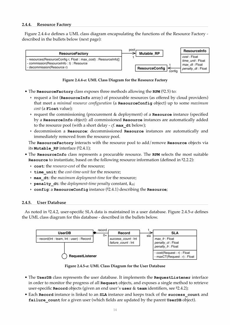
Figure 2.4.4-a defines a UML class diagram encapsulating the functions of the Resource Factory - described in the bullets below (next page):
!Figure 2.4.4-a: UML Class Diagram for the Resource Factory
• The ResourceFactory class exposes three methods allowing the RPM (§2.5) to:‣ request a list (ResourceInfo array) of procurable resources (as offered by cloud providers)
that meet a minimal resource configuration (a ResourceConfig object) up to some maximum cost (a Float value);
‣ request the commissioning (procurement & deployment) of a Resource instance (specified by a ResourceInfo object): all commissioned Resource instances are automatically added to the resource pool (with a short delay - cf. max_dt below);
‣ decommission a Resource: decommissioned Resource instances are automatically and immediately removed from the resource pool.
The ResourceFactory interacts with the resource pool to add/remove Resource objects via its Mutable_RP interface (§2.4.1);
• The ResourceInfo class represents a procurable resource. The RPM selects the most suitable Resource to instantiate, based on the following resource information (defined in §2.2.2):‣ cost: the resource-cost of the resource;‣ time_unit: the cost-time-unit for the resource;‣ max_dt: the maximum deployment-time for the resource;‣ penalty_dt: the deployment-time penalty constant, kdt;‣ config: a ResourceConfig instance (§2.4.1) describing the Resource;
2.4.5. User Database
As noted in §2.4.2, user-specific SLA data is maintained in a user database. Figure 2.4.5-a defines the UML class diagram for this database - described in the bullets below.
!Figure 2.4.5-a: UML Class Diagram for the User Database
• The UserDB class represents the user database. It implements the RequestListener interface in order to monitor the progress of all Request objects, and exposes a single method to retrieve user-specific Record objects (given an end user’s user & team identifiers, see §2.4.2);
• Each Record instance is linked to an SLA instance and keeps track of the success_count and failure_count for a given user (which fields are updated by the parent UserDB object).
ResourceFactory- resources(ResourceConfig r, Float : max_cost) : ResourceInfo[]- commission(ResourceInfo : t) : Resource- decommission(Resource r)
ResourceInfocost : Floattime_unit : Floatmax_dt : Floatpenalty_dt : FloatResourceConfig
config
1
Mutable_RP1
pool
UserDB- record(Int : team, Int : user) : Record
Recordsuccess_count : Intfailure_count : Int
0+record
SLA
- cost(Request : r) : Float- maxCT(Request : r) : Float
max_fr : Floatpenalty_ct : Floatpenalty_fr : Float
1
sla
RequestListener
!14

• An SLA instance captures relevant information from consumer facing SLAs (see §2.2.1), namely: ‣ max_fr: the maximum failure-rate for requests;‣ penalty_ct: the completion-time penalty constant, kct; ‣ penalty_fr: the failure-rate penalty constant, kfr;‣ a cost method returning the financial cost (to the user) of a given request;‣ a max_ct method returning the maximum completion-time for a given request.
We will assume that consumer-facing SLAs are standardised, and come in just three varieties: ‘bronze’ (low cost, weak QoS), ‘silver’ (mid-range) and ‘gold’ (high cost, strong QoS).
2.5. Resource Pool Manager (RPM)
Figure 2.5-a defines a UML class diagram for the RPM - described in the bullets below.
!Figure 2.5-a: UML Class Diagram for the RPM
• The RPM class represents the Resource Pool Manager (RPM), which:‣ extends the RequestQueue class (in the complete ETICS system requests are forwarded to
the RPM from the Configuration Web-Service), adding only a run() method for activation (the RPM then runs continuously in its own thread);
‣ implements the RequestListener interfaces (§2.4.2) to monitor the progress of requests; ‣ forwards (resource tagged) requests to the ExecutionEngine for execution;‣ queries the UserDB for user-specific QoS details;‣ uses the ResourceFactory to obtain lists of procurable resources, and to (de)commission Resources, but can otherwise only directly interact with the resource pool through its Monitored_RP interface;
An outline of the regulatory behaviour of the RPM w.r.t. the resource pool was given in §2.3.2 (above), while its implementation is discussed in §3.5 (below).
2.6. Simulator
As a prototype, the RPM will be tested within a simulation environment, the UML class diagram for which is given in Figure 2.6-a (next page) and described in the subsequent bullets.
!Figure 2.6-a: UML Class Diagram for the Simulator
RPM
RequestListener
- run()Monitored_RP
1pool
UserDB1database
ExecutionEngine1engine
ResourceFactory factory1
RequestQueue
Simulator- run()
ResourcePool
RPM
ExecutionEngine UserDB
ResourceFactory
1
1
1
1
1
RequestGenerator1
- nextRequest() : RequestUserModel
1model
!15

• The Simulator class is little more than a container for the RPM, its environment (UserDB, ExecutionEngine, ResourceFactory & ResourcePool), and a RequestGenerator object.
• The RequestGenerator class represents a timed sequence of requests, and:‣ exposes a single method nextRequest() returning the next Request in the sequence;‣ is associated with a UserModel, encapsulating probabilistic data about how the service is
used, from which data the sequence of requests is constructed - as explained in §2.6.1 below. • The simulation then runs as a continuous loop. On each cycle the Simulator instance:
‣ invokes nextRequest(), on the RequestGenerator, with result R;‣ waits until R.time (the scheduled time of the request);‣ then invokes addRequest(R) on the RPM: adding the request to the RPM’s request queue;
2.6.1. User Model
As noted above, the UserModel captures probabilistic service usage data and serves as the basis for simulating requests. For simplicity, we make the following assumptions:
• The ETICS service is hosted at a single data-centre with a specific geographical location; • Developers work in teams (of say 10-100 individuals) on collaborative software projects, where
each member of a given team:‣ has the same standard working hours, say: 9-5, Monday-Friday (with occasional overtime),
and geographical location, the international time-zone of which offsets the working hours relative to the data centre hosting the ETICS service;
‣ is subject to identical QoS terms, i.e. a single (consumer-facing) SLA is agreed between the team and the ETICS provider.
The UserModel, as indicated by the UML class diagram in Figure 2.6.1-a, is then essentially a collection of Team instances, each with the following fields/relations:
• index: a unique identifier for the team;‣ corresponds to the team identifier in the Request class (§2.4.2);
• timezone: a relative time offset (−12 to +12 hours);• user_count: the number of developers in the team;
‣ the user identifier in the Request class (§2.4.2) denotes the nth member of the team;• SLA: the SLA governing each team member’s use of the ETICS service (see §2.4.5.);• config: an array of 1+ ResourceConfig instances (§2.4.1.), one of which is randomly assigned
to each request generated by the team;
!Figure 2.6.1-a: UML Class Diagram for the User Model
Requests can then be generated according to the following (or similar) simple rules:• let p = k * user_count be the size of the collaborative software project that the team is working
on, where k is some constant.• each developer generates a random number (say, between 20..50) of small scale ad-hoc requests
(say, request_size = 1..5% × p) at random intervals during the working day. • each team generates one large scale scheduled request (request_size = p) at, say, midnight each
working day (i.e. corresponding to a regular ‘nightly build’).
UserModel Team0+
teamindex : Inttimezone : Intuser_count : Int
SLA1
sla0+
config1+ ResourceConfig
!16

3. Implementation
This section describes an initial ABS implementation of the RPM, mock-up ETICS components and simulation environment specified in the previous section. This initial model comprises the twelve ABS modules listed in Table 3-a. The complete code is available at the following link:
• https://envisage.ifi.uio.no:8080/redmine/projects/abstools/repository/revisions/master/raw/examples/T4.4/D4.4.1/ENGCaseStudy_ETICS.abs.
Table 3-a: List of ABS Modules
Most of the modules are a fairly straightforward translation of the UML class diagrams given in the previous sections into ABS . Subsections §3.1 - §3.5 below provide sample code snippets from 10
select modules to highlight various features of the implementation, while Section §3.6 lists various ABS-specific issues encountered during the code development.
Module Module Contents See
Interfaces Classesclass “XImpl” implements interface “X”
Common User-defined data-type & functional definitions, and Exception Types §3.3
Config ResourceConfigImpl
Engine TimeOut TimeOutImpl ExecutionEngineImpl
§3.4
Factory ResourceInfoImpl ResourceFactoryImpl
Generator RequestData RequestGenerator
UserModel Team
RequestDataImpl RequestGeneratorImpl
UserModelImpl TeamImpl
Interfaces ResourceConfig ResourceListener
Resource Monitored_RP Mutable_RP
Queriable_RP ResourceInfo
ResourceFactory Request
RequestListener RequestQueue
ExecutionEngine UserDB Record SLA RPM
Pool ResourcePool
Request RequestImpl
Resource ResourceImpl §3.2
RPM RPMImpl §3.5
Simulator Simulator §3.1
UserDB MutableQoS MutableQoSImpl UserDBImpl
With appropriate adaptations for ABS datatype and interface/class specialisation idiosyncrasies.10
!17

3.1. Simulator
The code snippet below captures the basic behaviour of the simulator, which: • first creates the required environment objects (UserDB, ResourcePool, ResourceFactory & ExecutionEngine), and the RPM - each in a distinct COG;
• creates a RequestGenerator in the local (simulator) COG;• performs a fixed number of simulation iterations: firing one request to the RPM per iteration.
class Simulator{
RequestGenerator generator = Nil;
Unit run(){
// create the environment objects (each in a separate COG) UserDB user_db = new UserDBImpl(); ResourcePool pool = new ResourcePoolImpl(); ResourceFactory factory = new ResourceFactoryImpl(pool); ExecutionEngine engine = new ExecutionEngineImpl(pool);
// create RPM RPM rpm = new RPMImpl(user_db, factory, engine, pool);
// create RequestGenerator (in the local COG) generator = new local RequestGenerator(user_db);
// simulation loop Int iterations = 100000; // an arbitrary value while (iterations > 0){ Unit u = this.fireNextRequest(); iterations = iterations - 1; }
} Unit fireNextRequest(){
// get the next request RequestData x = generator.nextRequest();
// wait for the specified delay Int delay = x.delay(); Time t = now(); await timeDifference(now(), t) > delay; // suspends the current process
// fire the request Request request = x.request(); Unit u = RPM!addRequest(request); // asynchronous
}
}
The simulator is then started from the main loop:
// MAIN { new Simulator(); }
Access to system states during simulation runs (for feedback/visualisation of execution progress and resource consumption under different usage assumptions) is expected to be supported by the simulation and querying tools developed in WP1 (Task T1.4).
!18
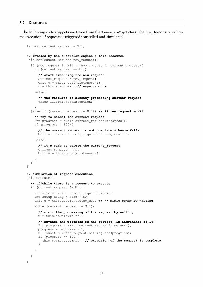
3.2. Resources
The following code snippets are taken from the ResourceImpl class. The first demonstrates how the execution of requests is triggered/cancelled and simulated.
Request current_request = Nil;
// invoked by the execution engine & this resource Unit setRequest(Request new_request){
if (new_request != Nil && new_request != current_request){ if (current_request == Nil){
// start executing the new request current_request = new_request; Unit u = this.notifyListeners(); u = this!execute(); // asynchronous
}else{
// the resource is already processing another request throw IllegalStateException;
} }else if (current_request != Nil){ // && new_request = Nil
// try to cancel the current request Int progress = await current_request!progress(); if (progress < 100){
// the current_request is not complete & hence fails Unit u = await current_request!setProgress(-1);
}else{
// it’s safe to delete the current_request current_request = Nil; Unit u = this.notifyListeners();
} } } // simulation of request execution Unit execute(){
// if/while there is a request to execute if (current_request != Nil){
Int size = await current_request!size(); Int setup_delay = size * 50; Unit u = this.doDelay(setup_delay); // mimic setup by waiting
while (current_request != Nil){
// mimic the processing of the request by waiting u = this.doDelay(size);
// advance the progress of the request (in increments of 1%) Int progress = await current_request!progress(); progress = progress + 1; u = await current_request!setProgress(progress); if (progress == 100){ this.setRequest(Nil); // execution of the request is complete }
}
}
}
!19
// delay = proportional to size (with some random variation) Unit doDelay(Int request_size){ Int delay = (request_size * 100) + 5 - random(10); Time t = now(); await timeDifference(now(), t) > delay; }
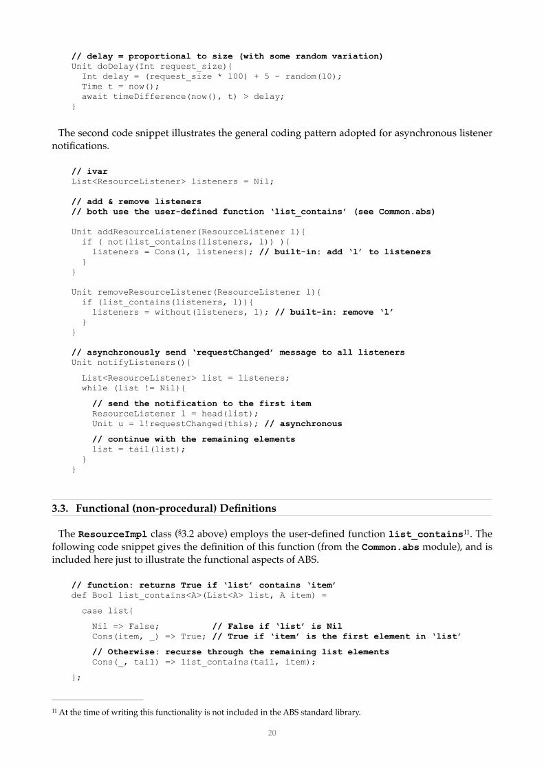
The second code snippet illustrates the general coding pattern adopted for asynchronous listener notifications.
// ivar List<ResourceListener> listeners = Nil;
// add & remove listeners // both use the user-defined function ‘list_contains’ (see Common.abs)
Unit addResourceListener(ResourceListener l){ if ( not(list_contains(listeners, l)) ){ listeners = Cons(l, listeners); // built-in: add ‘l’ to listeners } }
Unit removeResourceListener(ResourceListener l){ if (list_contains(listeners, l)){ listeners = without(listeners, l); // built-in: remove ‘l’ } } // asynchronously send ‘requestChanged’ message to all listeners Unit notifyListeners(){
List<ResourceListener> list = listeners; while (list != Nil){
// send the notification to the first item ResourceListener l = head(list); Unit u = l!requestChanged(this); // asynchronous
// continue with the remaining elements list = tail(list); } }
3.3. Functional (non-procedural) Definitions
The ResourceImpl class (§3.2 above) employs the user-defined function list_contains . The 11
following code snippet gives the definition of this function (from the Common.abs module), and is included here just to illustrate the functional aspects of ABS.
// function: returns True if ‘list’ contains ‘item’ def Bool list_contains<A>(List<A> list, A item) =
case list{
Nil => False; // False if ‘list’ is Nil Cons(item, _) => True; // True if ‘item’ is the first element in ‘list’
// Otherwise: recurse through the remaining list elements Cons(_, tail) => list_contains(tail, item);
};
At the time of writing this functionality is not included in the ABS standard library. 11
!20

3.4. Execution Engine
The code snippets presented in this section are from the ExecutionEngineImpl class, and serve to show how the Execution Engine handles requests received from the RPM. The code is essentially an implementation of the flow-chart shown earlier in Figure 2.4.3-b.
The first snippet defines a helper interface & class for postponed requests (covering the case that the resources assigned to requests by the RPM are not immediately available). Each instance of this class is a timer, which (on creation) suspends for a predefined ‘timeout’ period, and then simply informs the Execution Engine that the timeout has occurred.
interface Postponed{ Request request(); Unit cancel(); }
class PostponedImpl( Request request, ExecutionEngineImpl engine, Int delay ) implements Postponed {
Bool cancelled = False;
Unit run(){
// wait for the timeout delay Time t = now(); await timeDifference(now(), t) > delay;
// notify the execution engine of the timeout if ( not(cancelled) ){ Unit u = engine!timedOut(request); } } Request request(){ return request; } Unit cancel(){ cancelled = True; } }
The following snippet defines the Execution Engine’s behaviour when it receives a request (via the addRequest(~) method inherited from the RequestQueue interface):
Unit addRequest(Request request){
// retrieve the resource assigned to the request from the pool ... String resource_id = await request!resourceId(); Resource resource = await pool!resource(resourceId);
if (resource == Nil){
// no resource was found, so the request fails // note: the UserDB is automatically notified of the failure Unit u = await request!setProgress(-1);
}else{ // is the resource free ? Request current = await resource!request(); // continued ...
!21

if (current == Nil){
// the resource is free: so execute the request immediately Unit u = await resource!setRequest(request);
}else{
// wait until the resource becomes free Unit u = this.postponeRequest(request, resource); // synchronous
} } }
The next snippet shows the implementation of the (private) postponeRequest method, which relies on a local dictionary associating resource identifiers with lists of Postponed objects.
Map<String, List<Postponed>> postponed_map = EmptyMap;
Unit postponeRequest(Request request, Resource resource){
// get the list of (any previously) postponed requests for the resource String resource_id = await resource!id(); List<Postponed> ps = lookup(postponed_map, resource_id);
// create a new Postponed object for the request in a new COG // ‘10000’ is the timeout period in ms Postponed p = new PostponedImpl(request, this, 10000);
// add the new Postponed object to the list pr = Cons(pending, ps); postponed_map = put(postponed_map, resource_id, ps);
// listen for changes to the resource's request … // the resource is free to execute a request if its current request is Nil Unit u = await resource!addResourceListener(this);
}
The following method (inherited by the ExecutionEngineImpl from the ResourceListener interface) is invoked by a resource when its request field changes value.
Unit requestChanged(Resource resource){
// get the list of (any previously) postponed requests for the resource String resource_id = await resource!id(); List<Postponed> ps = lookup(postponed_map, resource_id);
// if there are pending requests if ( not(isEmpty(ps)) ){
// is the resource free now? Request request = await resource!request(); if (request == Nil){
// the resource is free, so get the oldest postponed request Postponed p = head(ps); Unit u = await p!cancel(); // cancel the timeout notification Request request = await p!request();
// execute this request immediately u = await resource!setRequest(request);
// the request is no longer postponed, so update the map ps = tail(ps); postponed_map = put(postponed_map, resource_id, ps);
}
} // continued ...
!22

if (isEmpty(ps)){ // there are no more postponed requests assigned to the resource // so we can stop listening to it Unit u = await resource!removeResourceListener(this); } }
Finally, if the assigned resource has not become available before a timeout, the Postponed object invokes the following (private) method on the ExecutionEngineImpl instance, which just marks the request as failed and destroys the Postponed object.
Unit timedOut(Postponed p){
// the request fails (due to timeout) Request request = await p!request(); Unit u = await request!setProgress(-1);
// remove the timeout from the pending list String resource_id = await request!resourceId(); List<Postponed> ps = lookup(postponed_map, resource_id); ps = without(ps, p); postponed_map = put(postponed_map, resource_id, ps);
}
3.5. RPM
The following code snippet is the current implementation of the RPM (class RPMImpl) - which at the moment is just a shell:
class RPMImpl ( UserDB user_db, ResourceFactory factory, ExecutionEngine engine, Monitored_RP pool ) implements RPM{ Unit run(){ // TODO - continuously search for optimal request <-> resource assignments // incl. elastically add/remove resources to/from the pool } // RequestQueue implementation Unit addRequest(Request r){ // TODO - received a new request } // RequestListener implementation Unit progressChanged(Request r){ // TODO - received an update on the progress of executing requests }
}
The implementation proper of the RPM will be reported in D4.4.2 (Resource-aware Modelling for the ENG Case Study, due in M22). The current idea is to develop a handful of distinct implementations, each employing a different decision algorithm. These different versions comprise a simple software product line, modelled in ABS by a feature model (with automatic code generation determined by appropriate feature selection).
!23

Figure 3.5-a shows an initial feature model for the ENG case study. Each of the three sub-features denotes a particular approach to implementing the RPM, as briefly described in the bullets below:
!Figure 3.5-a: Feature Model for the ENG Case Study
• Baseline: A trivial ‘worst-case’ algorithm serving as baseline for comparison, e.g. in the most simple case: the RPM commissions a new resource for each request received, decommissioning the resource once the request is complete.
• Drive-Based: Denoting a particular sub-class of action selection mechanisms, originally derived 12
from ethological ‘drive’ models of animal behaviour, but more properly characterised as based on homeostatic principles - notable examples include [2], [3] and [4]. These mechanisms are inherently distributed with elastic resource requirements (cf. the non-functional constraints described in §2.3.2), and are thus good candidates for modelling in (resource-aware) ABS.
• Envisage: At least two options:‣ The Envisage tools can be used to establish (possible) runtime criteria for switching between
simple, pre-defined request scheduling and/or resource commissioning policies (akin to Usage Scenario 2 from the DOW Part B, page 8, Figure 7), which criteria can then be used at runtime to decide the most appropriate policy.
‣ More ambitiously, experience in applying the Envisage toolset to develop the RPM will help to establish whether it is possible to implement the RPM exclusively in terms of the toolset - in particular: utilising the fully automated Envisage hybrid analysis/simulation tools (from WP3) at runtime to determine the most appropriate request/resource configurations.
As already stated, these algorithms will be developed in ABS, and (in addition to their resource management role within the ETICS service) will reflectively schedule their own internal processes and manage the resources that execute these processes. To this end, they will also make use of:
• standard ABS primitives and APIs for dealing with processes & resources - i.e. (at the time of writing) the Scheduler, Process and DeploymentComponent primitives/types (defined in the built-in ABS modules ABS.Scheduler & ABS.DC );13
• autonomous monitors (cf. Task T2.3) for detecting significant events, e.g. runtime criteria for policy switching (above), or (if possible) preemptive warnings of failures and demand spikes.
Likewise, the development of the algorithms will employ the Envisage tools (developed in WP3) and methodology to:
• automatically generate executable versions in Java;• verify conformance of the generated code to the ABS models; and• test for conformance of the ABS models to non-functional constraints (service contracts);For comparative purposes, the various RPM algorithms may be judged according to the simple
profit metric defined in §2.2.3. Note, however, that the main objective is not to evaluate the utility of the different RPM algorithms per se, but to evaluate the utility of ABS and the Envisage toolset/methodology for the development of the RPM.
ENG Case Study
Baseline EnvisageDrive-Based …
e.g. see https://en.wikipedia.org/wiki/Action_selection.12
Included in the ABS source file: abslang.abs.13
!24

3.6. Initial Comments
The following bullets lists some of the main difficulties that were encountered during the initial development of the ABS implementation of the RPM & Simulator .14
• A lack of comprehensive and up-to-date reference documentation for the ABS language and (in particular) the standard libraries - e.g. the primary documentation for built-in datatypes and functions consists of sparse inline comments in the abslang.abs source code file.
• The ABS plugins for the Eclipse IDE used to develop the implementation model are unstable 15
(exhibiting repeated low-level compiler exceptions).• A lack of high-level APIs for file-system/database access, e.g. for the UserDB or UserModel.• No support for class inheritance , i.e. in ABS there are no sub-classes inheriting (re-using) code 16
from their parent classes, and no calls to ‘super’ in class methods . This departure from the 17
‘usual’14 class-based principles entails quite a radical shift in thinking about code design.• The constraint that synchronous (blocking) method calls are only permitted between objects in
the same COG blurs the distinction between synchronous (blocking) and asynchronous (non-18
blocking) calls. To illustrate, consider the following naive code snippet:
interface X{ Int a(); }
interface Y{ Int b(); }
class Z (X x) implements Y{ Int b(){ Int a = x.a(); // synchronous (blocking) call return a + 1; } }
The synchronous invocation x.a() used here appears fairly natural14 but will in fact result in a runtime error whenever the Z instance and its x parameter reside in different COGs. To avoid this possibility, an asynchronous non-blocking call must be used to mimic the intended blocking behaviour - which is somewhat counter-intuitive:
Int a = await x!a(); // asynchronous (non-blocking) call
• On a lesser note: the ABS syntax requires that the results of all method invocations are assigned to variables, even for methods with no return values (i.e. return type Unit). So, given:
interface X{ Unit a(); }
The following code must be used to invoke the method a() on an instance, x, of X:
Unit u = x.a();
• Related to the last point, ABS does not support nested method calls, so the following is illegal:
Int a = x.foo( y.goo() );
The correct form is:
Int b = y.goo(); Int a = x.foo(b);
From the perspective of a novice ABS developer with experience of standard OO languages (Java, Objective-C, …). 14
Eclipse Java IDE: www.eclipse.org.15
An interface may extend another interface, but a class cannot extend another class, it can only implement interfaces.16
Code re-use in ABS is instead achieved through Software Product Line methods - see: http://docs.abs-models.org/.17
Explained in [1], p20 (section “Location Types”).18
!25

4. Relevance To Project Goals
The overall relevance of the ENG case study to the project goals has two aspects:• First, the case study uses the ABS tools/methodology to develop a (prototype) Resource Pool
Manager (RPM) component for the ETICS service, together with mock-ups of other relevant ETICS components and a simulation environment for testing the RPM’s behaviour. The RPM will be implemented with a scalable distributed architecture, and will elastically manage the computational resources on which it executes in order to adapt to dynamic request rates. The RPM, mock-up components and simulation environment will all be developed entirely in ABS, exploiting the language’s built-in features for event monitoring & elastic resource deployment, and employing Envisage analytic and simulation tools to ensure scalable robust performance.
• Second, the role/function of the RPM within the ETICS architecture is to elastically manage the virtual computational resources used by ETICS to respond to end user requests. This function is independent of the Envisage development methodology used to construct the RPM, but it never-the-less serves as a concrete illustration of some of the issues involved in elastic resource management (in particular from the business perspective of operating services at profit). In this sense the case study is intended to provide useful input to the technical work packages.
The next subsection describes how the case study relates to the Envisage objectives & milestones.
4.1. Relation to Envisage Objectives & Milestones
This section relates the ENG case study to the Envisage objectives (O1 - O6) and milestones (M1 -
M5), summarised for reference in Table 4.1-a, and w.r.t. to the timeline for WP4 deliverables in Figure 4.1-b (next page) . 19
Table 4.1-a: Summary of Envisage Objectives, Milestones, Outcomes & Timing
Objective Objective Description Milestone Outcomes Month
O1 Foundations of computation with
virtualised resources
M2 (modelling capabilities)
Semantic framework for scalable architectures, infrastructures, and
virtualised resources.
18
O2 Behavioural specification language
for virtualised resources
M2 Resource-aware, abstract behavioural specification language and its prototype
simulator.
18
O3 Design-by-contract methodology for service contracts
M3 (design-by-contract of services)
Formal specification language for service contracts.
24
O4 Model conformance demonstrator
M4 (tool demonstrator)
Demonstrator for the conformance of generated or legacy code to the abstract
model.
30
O5 Model analysis demonstrator
M4 Runtime support for the resource analysis and for the validation with the SLA.
30
O6 Demonstration of Impact
M1 (modelling of the case studies)
M5 (project assessment)
Case studies artefacts and their formal verification; Envisage toolset available as a
service, Public releases, Academia and Industrial dissemination.
12
36
The table & figure are respectively adapted from Figures 8 & 9 (page 8) in the Envisage DOW (Part B) 19
!26

!Figure 4.1-b: Timeline for WP4 w.r.t. Objectives & Milestones
The present deliverable represents the means of verification for Milestone M1 (modelling of the case studies) and hence covers the initial M12 outcome of Objective O6 (demonstration of impact). The bullets below highlight how the ENG case study impacts the remaining objectives.
• O1 - Foundations of Computation with Virtualised Resources:The ENG case study provides a service scenario in which the elastic management of virtualised resources is central. This deliverable offers a detailed account of what (from the perspective of industry) such elastic management entails, and serves as input to WP1. In particular, we have:‣ provided an object-oriented model (§2.4 & §2.5) of the ETICS service; ‣ detailed how this service employs elastically provisioned virtual computing resources for
the distributed execution of both end-user requests and the decision algorithm employed by the RPM;
‣ enumerated the relevant properties of computational resources (cf. T1.2); and ‣ specified an appropriate level of abstraction for modelling resource deployment (cf. T1.3).
In §2.6.1 (‘User Model’) we also outlined a probabilistic model of service demand, from which estimates of workload (and in particular, of dynamic variation in workload) can be derived.
• O2 - Behavioural Specification Language for Virtualised Resources:The RPM, mock-up ETICS components and simulation environment will all be implemented (as executable models) entirely in the abstract behavioural specification language (ABS) to be developed within WP1. An initial ABS implementation is presented in §3, to be elaborated in future deliverables. In particular:‣ the ResourceFactory will be updated in line with the results of T1.1 (modelling support
for scalable infrastructure - esp. dynamic creation and management of virtual machines);‣ likewise the Resource model will be updated in line with the results of T1.2 (modelling of
resources); and ‣ the implementation of the RPM will incorporate the results of T1.3 (deployment modelling)
as part of its decision making processes.
• O3 - Design-by-Contract Methodology for Service Contracts:The ENG case study is defined in terms of the relation between functional service components (in particular the RPM) and their required non-functional properties (derived from consumer & cloud provider facing SLAs). This deliverable provides detailed definitions of the relevant QoS terms, and explains (in §2.3.2) how these terms impact:‣ the functional properties of the service (in particular, the internal calculations of the RPM);‣ the non-functional properties of the service - i.e. the actual completion-times & failure-rates (as
opposed to the normative values specified in SLAs); and‣ the overarching business-level concerns of the service (for simplicity, just profit).
As such, this deliverable provides direct input to task T2.2, both for the specification of QoS, and for defining criteria for the conformance of the service to QoS.
Initial User Requirements
Case Study: Initial Modelling
Case Study: Resource Modelling
Case Study: Assurance
Overall Assessment
Objectives O1, O2 O3 O4, O5
1 7 10 22 34 36
Milestones M2 M3M1 M4
month
M5O6O6
!27
• O4 - Model Conformance Demonstrator:As stated above, the RPM, mock-up ETICS components & simulation environment will all be modelled entirely in ABS. The ENG case study will then use the results of T3.1 to automatically generate an executable version in Java, and to ensure that this code conforms to the operational semantics of the source ABS model. The development of the ABS model will also make extensive use of the automatic test-case generation mechanisms (T3.5), and the prototype simulator (T1.4) for debugging, tracing the execution, and testing of:‣ the distributed simulator & ETICS components - i.e. the overall flow of requests from the RequestGenerator, to the RPM, to the ExecutionEngine, to Resource instances, as well the various interactions (in particular the asynchronous ~Listener notifications and timed interrupts) between these objects and the ResourceFactory, UserDB, and UserModel.
‣ the distributed decision algorithm(s) employed by the RPM.Future deliverables will also investigate the use of dedicated monitoring add-ons (T2.3) to monitor the status (i.e. composition, QoS & ongoing tasks) of the ResourcePool.
• O5 - Model Analysis Demonstrator:The ENG case study will use the tools developed in WP3 to verify the ABS model of the RPM against non-functional requirements. Specifically, we will employ a hybrid (T3.4) approach based mainly on formal verification (T3.2) & resource analysis (T3.3), but likely also requiring input from test-case execution (T3.5) and possibly monitoring (T2.3). The basic aim is to ensure the scalability and cost-effectiveness of the RPM (as described in §2.3.2).
4.2. Summary
This deliverable constitutes an initial model of the ENG case study, the objective of which is to employ the Envisage tools & methodology to develop an automated Resource Pool Manager (RPM) component for the elastic management of the computational resources utilised by ENG’s ETICS service. The deliverable has presented a detailed account of, and requirements specification for, the RPM (in terms of both functional & non-functional properties), for mock-up versions of the other ETICS architectural components with which the RPM interacts, and for a simulation environment for evaluating the performance of the RPM in the face of diverse usage patterns. A preliminary ABS implementation of the RPM and simulator has also been developed (to be expanded and improved in subsequent deliverables), and some initial observations on the status and use of ABS recorded. Finally, we have outlined how the ENG case study both provides input to and utilises the results of the technical work-packages, and how in general terms it contributes to the main project objectives.
!28

Bibliography
Web links are valid as of December 10th 2014.
[1] Hähnle, R. (2013) The Abstract Behavioural Specification Language: A Tutorial Introduction : FMCO 2012, LNCS 7866, pp. 1-37, 2013.
[2] Bryson, J.J. (2003) The Behaviour-Oriented Design of Modular Agent Intelligence : Agent Technologies, Infrastructures, Tools & Applications for e-Services, R. Kowalszyk, J. P. Müller, H. Tianfield and R. Unland, eds., pp. 61-76, Springer, 2003.
- available at: http://www.cs.bath.ac.uk/%7Ejjb/ftp/AgeS02.pdf
[3] Tyrrell, T. (1993). Computational Mechanisms for Action Selection : PhD thesis, University of Edinburgh, Centre for Cognitive Science.
- available at: http://w2mind.computing.dcu.ie/worlds/w2m.TyrrellWorld/tyrrell_phd.pdf
[4] Pezzulo, G., Calvi, G. & Castelfranchi, C. (2007). DiPRA - Distributed Practical Reasoning Architecture : IJCAI ’07, pp. 1458-1463.
- available at: http://www.ijcai.org/papers07/Papers/IJCAI07-235.pdf
!29