Deliquification vs. Artificial Lift - MuleShoe...
27
1 Deliquification vs. Artificial Lift By David Simpson, PE MuleShoe Engineering Copies available at www.muleshoe-eng.com/id2.html Deliquification vs. Artificial Lift • Introduction • Deliquification methods that evolved from Artificial Lift • Gas-specific deliquification methods • Conclusion
Transcript of Deliquification vs. Artificial Lift - MuleShoe...
1
Deliquification vs.Artificial Lift
By David Simpson, PEMuleShoe Engineering
Copies available at www.muleshoe-eng.com/id2.html
Deliquification vs. Artificial Lift
• Introduction• Deliquification methods that evolved from
Artificial Lift• Gas-specific deliquification methods• Conclusion

2
Introduction
• In the last 50-100 years, gas has gone from being a waste product that hindered oil production to a primary, sought after product
• Current gas prices are causing operators to rethink the terms “economic limit” and “abandonment pressure”
• Operators are reaching original abandonment pressure while the field is still very profitable
• What do they have to do differently to remain profitable down to very low reservoir pressures?
• The biggest difference is “Deliquification”
Working Definitions
• Artificial Lift: application of external energy to lift a commercial product from reservoir depths to the surface
• Deliquification: application of energy to remove an interfering liquid to enhance gas production
• The key difference is that it matters where and in what condition artificially-lifted oil ends up, but water just needs to be gone– Evaporation is a reasonable deliquification method, but it would be
an artificial-lift failure– Pump discharge below a packer is reasonable deliquification but
not good for artificial lift
3
Net Positive Suction Head (NPSH)
• Net Positive Suction Head is the amount of external pressure at the inlet to a pump.
• The Required NPSH (NPSH-r) is the amount of external pressure required to ensure the pump operates full of liquid.
• The Available NPSH (NPSH-a) is the amount of external pressure available at the pump suction.
• It generally doesn’t matter if the NPSH comes from an actual hydrostatic head or an applied pressure (as long as the pump sees continuous-phase liquid).
• NPSH-r is very dependent upon fluid properties (mainly the boiling point, gas solubility, and vapor pressure)
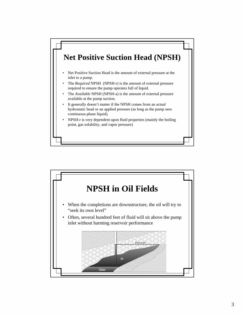
NPSH in Oil Fields
• When the completions are downstructure, the oil will try to “seek its own level”
• Often, several hundred feet of fluid will sit above the pump inlet without harming reservoir performance
4
NPSH in Gas Fields
• Any fluid above the perfs will add to the backpressure on the formation
• Backpressure is a significant factor in production rate, but it is not simple:– Many wells have a “pressure window” that maximizes production– The window is defined by the sum of all sources of restriction to
flow (e.g., friction, fluid interference within reservoir, and condensation)
– Going outside of this pressure window will reduce gas rate– The pressure window moves with time
• There is never a clear relationship between NPSH-a and backpressure
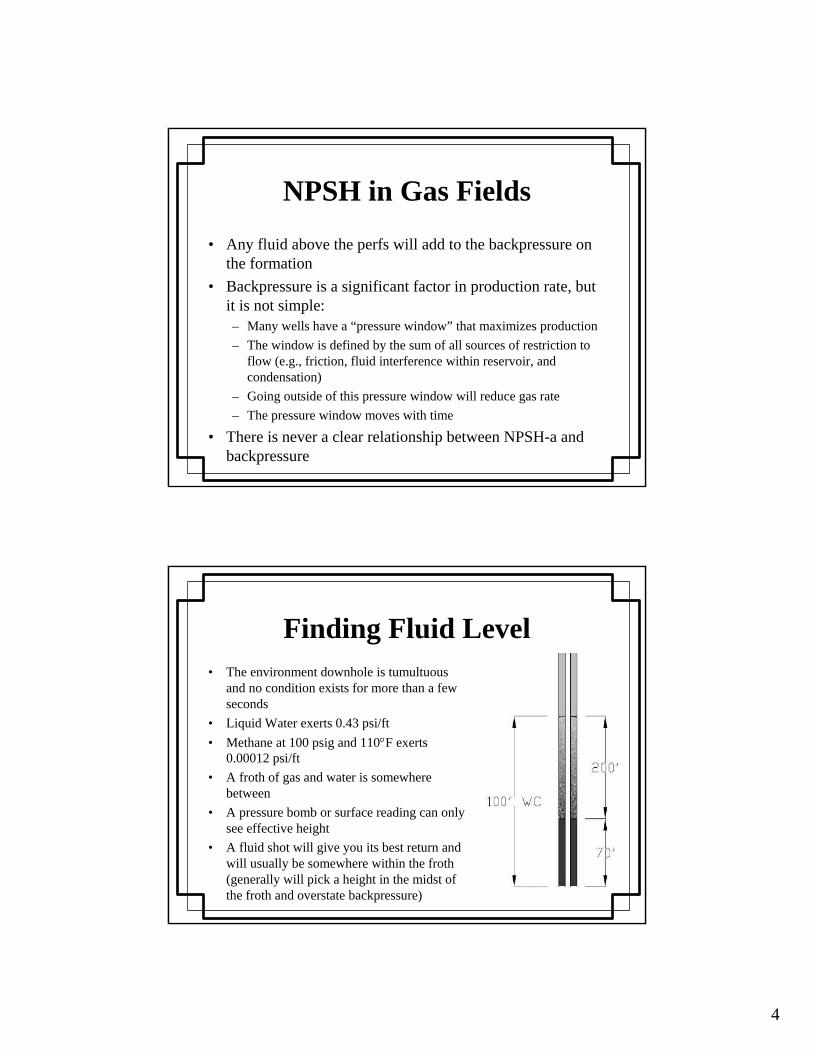
Finding Fluid Level• The environment downhole is tumultuous
and no condition exists for more than a few seconds
• Liquid Water exerts 0.43 psi/ft• Methane at 100 psig and 110°F exerts
0.00012 psi/ft• A froth of gas and water is somewhere
between• A pressure bomb or surface reading can only
see effective height• A fluid shot will give you its best return and
will usually be somewhere within the froth (generally will pick a height in the midst of the froth and overstate backpressure)
5
Where do you go to get more NPSH?
• Change technology:– A rod pump needs less NPSH than a jet pump– A progressing-cavity pump needs less than a rod pump
• Downhole equipment:– Gas separators– Mechanical devices to trip traveling valves– Vent piping, holes in tubing or pump
• Remove pressure drops (screens, tail pipes, standing valves). CAUTION:– Each of these devices has a reason for being there– Removing them is not without risks
Rat Hole
• Defined: space within the wellbore below the producing strata.
• Functions:– Collect fill and other wellbore trash– Raise NPSH-a without adding hydrostatic head on the
formation• Downside of placing pump in the rat hole:
– Can concentrate solids in the pump suction– Harder to remove pump heat in the small volume of
liquids around the pump

6
Technologies that evolved from Artificial Lift
• Pump-off control• Stroking pumps• Progressing cavity pumps (PCP)• Electric submersible pumps (ESP)• Gas lift• Jet pumps• Surfactants
Pump-off Control
• Inflow to gas wells is never very constant• Pump-capacity requirements will change many times per
day• Using periodic fluid level shots will result in pumps
running at the wrong speed most of the time• Gross-level surface indications (e.g., flow rate, tubing-
casing differential, etc.) happen too late to support needed changes (i.e., by the time you see the problem it is either over or has gotten much worse)
7
Pump-off control example• Well makes 5 bbl/day and 25 MCF/d• Rod Pump
– 1-1/2 pump inside 2-3/8 tubing– 40-inch stroke– 4 strokes/min– Pump capacity 44 bbl/day
• Running on stop clock, 30 min on, 4.5 hours off• Problem
– The well averages 5 bbl/day– As hydrostatic head changes during the cycles the flow rate
fluctuates wildly and pump is always gas locked
• Stop/start control works better in oil than in gas wells
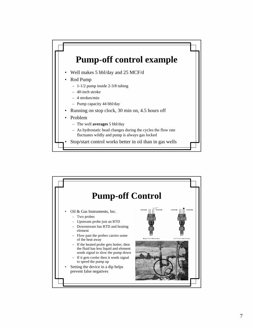
Pump-off Control• Oil & Gas Instruments, Inc.
– Two probes– Upstream probe just an RTD – Downstream has RTD and heating
element– Flow past the probes carries some
of the heat away– If the heated probe gets hotter, then
the fluid has less liquid and element sends signal to slow the pump down
– If it gets cooler then it sends signal to speed the pump up
• Setting the device in a dip helps prevent false negatives
8
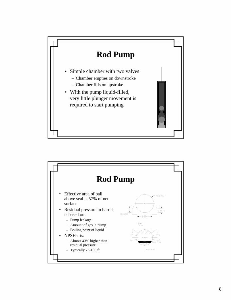
Rod Pump
• Simple chamber with two valves– Chamber empties on downstroke– Chamber fills on upstroke
• With the pump liquid-filled, very little plunger movement is required to start pumping
Rod Pump• Effective area of ball
above seal is 57% of net surface
• Residual pressure in barrel is based on:– Pump leakage– Amount of gas in pump– Boiling point of liquid
• NPSH-r is:– Almost 43% higher than
residual pressure– Typically 75-100 ft
9
Rod Pump Produced Gas Lock
• If the pump is liquid-filled, very little rod movement required to open traveling valve.
• If the pump has considerable dissolved or free gas: – It must compress the gas to above discharge hydrostatic
head before the traveling valve will open.– At 3,000 ft depth with 20 psig bottom-hole pressure the
gas must compress to over 40 ratios.– The pump will travel up and down without pumping
until • Leakage past the plunger fills the barrel with enough liquid to
open the traveling valve, or• Bottom-hole pressure rises enough to open standing valve
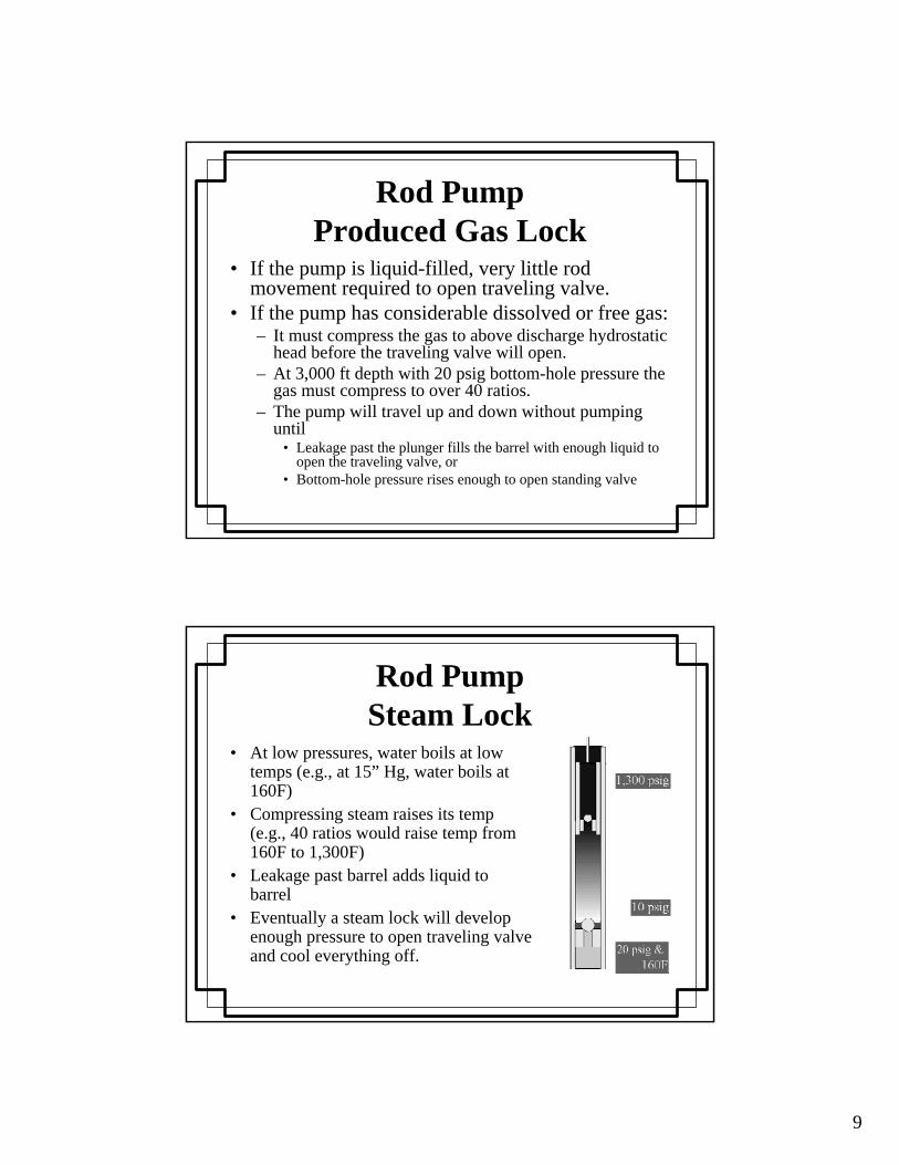
Rod PumpSteam Lock
• At low pressures, water boils at low temps (e.g., at 15” Hg, water boils at 160F)
• Compressing steam raises its temp (e.g., 40 ratios would raise temp from 160F to 1,300F)
• Leakage past barrel adds liquid to barrel
• Eventually a steam lock will develop enough pressure to open traveling valve and cool everything off.
10
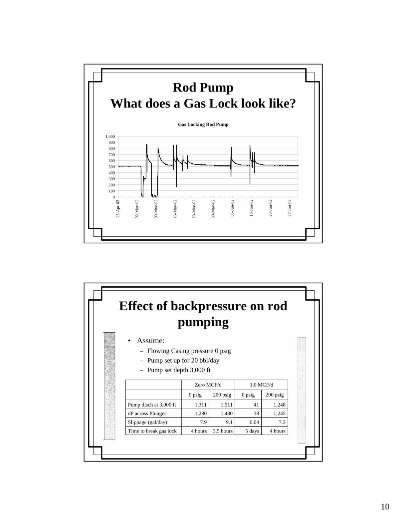
Rod PumpWhat does a Gas Lock look like?
Gas Locking Rod Pump
0100200300400500600700800900
1,000
25-A
pr-0
2
02-M
ay-0
2
09-M
ay-0
2
16-M
ay-0
2
23-M
ay-0
2
30-M
ay-0
2
06-J
un-0
2
13-J
un-0
2
20-J
un-0
2
27-J
un-0
2
Effect of backpressure on rod pumping
3.5 hours4 hoursTime to break gas lock
9.17.9Slippage (gal/day)
1,4801,280dP across Plunger
1,5111,311Pump disch at 3,000 ft
200 psig0 psig
Zero MCF/d
• Assume:– Flowing Casing pressure 0 psig– Pump set up for 20 bbl/day– Pump set depth 3,000 ft
5 days
0.04
38
41
0 psig
4 hours
7.3
1,245
1,248
200 psig
1.0 MCF/d
11
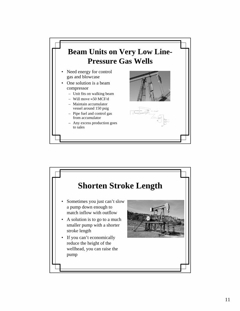
Beam Units on Very Low Line-Pressure Gas Wells
• Need energy for control gas and blowcase
• One solution is a beam compressor– Unit fits on walking beam– Will move ≈50 MCF/d– Maintain accumulator
vessel around 150 psig– Pipe fuel and control gas
from accumulator– Any excess production goes
to sales
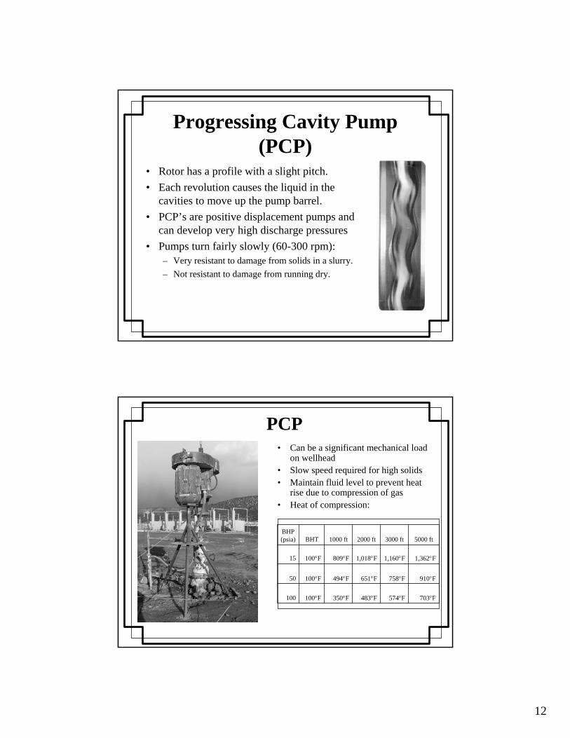
Shorten Stroke Length
• Sometimes you just can’t slow a pump down enough to match inflow with outflow
• A solution is to go to a much smaller pump with a shorter stroke length
• If you can’t economically reduce the height of the wellhead, you can raise the pump
12
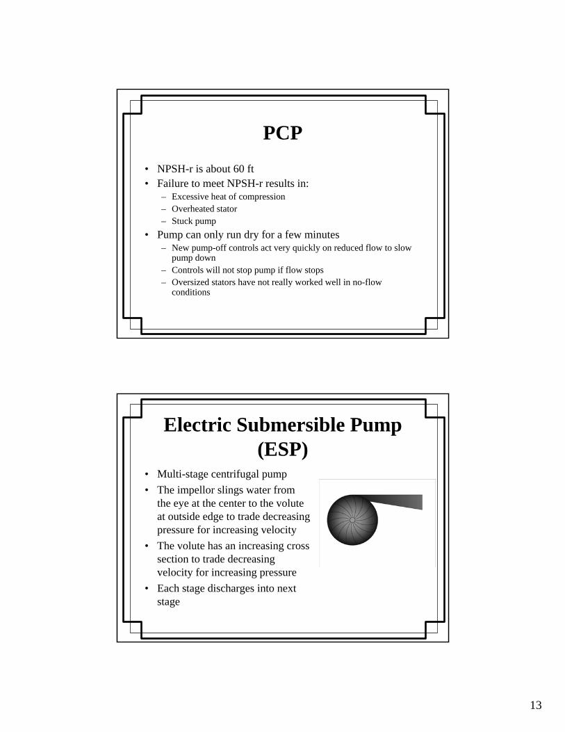
Progressing Cavity Pump (PCP)
• Rotor has a profile with a slight pitch.• Each revolution causes the liquid in the
cavities to move up the pump barrel.• PCP’s are positive displacement pumps and
can develop very high discharge pressures• Pumps turn fairly slowly (60-300 rpm):
– Very resistant to damage from solids in a slurry.– Not resistant to damage from running dry.
PCP
703°F 574°F 483°F 350°F 100°F100
910°F 758°F 651°F 494°F 100°F50
1,362°F 1,160°F 1,018°F 809°F 100°F15
5000 ft3000 ft2000 ft1000 ftBHTBHP (psia)
• Can be a significant mechanical load on wellhead
• Slow speed required for high solids• Maintain fluid level to prevent heat
rise due to compression of gas• Heat of compression:
13
PCP• NPSH-r is about 60 ft • Failure to meet NPSH-r results in:
– Excessive heat of compression – Overheated stator– Stuck pump
• Pump can only run dry for a few minutes– New pump-off controls act very quickly on reduced flow to slow
pump down– Controls will not stop pump if flow stops– Oversized stators have not really worked well in no-flow
conditions
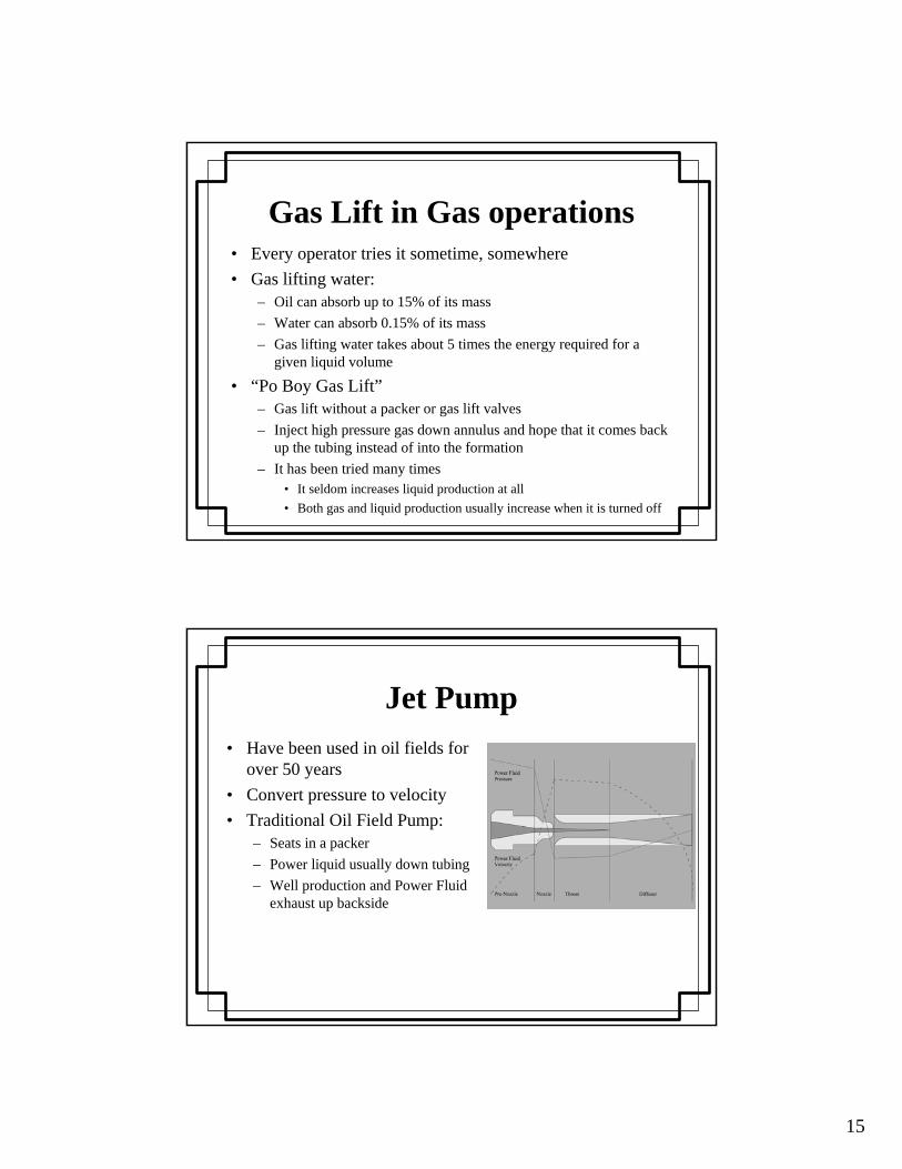
Electric Submersible Pump (ESP)
• Multi-stage centrifugal pump• The impellor slings water from
the eye at the center to the volute at outside edge to trade decreasing pressure for increasing velocity
• The volute has an increasing cross section to trade decreasing velocity for increasing pressure
• Each stage discharges into next stage

14
ESP• NPSH-r typically 150 ft• Without adequate NPSH:
– The first stage will cavitate.– The surface of the first-stage impellor will lose efficiency. – Subsequent stages will cavitate.
• Sometimes you can intermit the pump to align capacity with well performance:– Stopping pump will empty tubing back into formation– A standing valve can prevent emptying, but allows solids to settle out.– Settling solids can seize the pump and or/seal the standing valve.– A hole in the tubing above standing valve will let the pump backflush,
but it steals capacity.• Sand screens, standing valves, and filters decrease NPSH-a.
Gas Lift• High pressure/high velocity gas is
injected into annulus above a packer through gas-lift valves in tubing
• Combination of:– Liquid absorbing gas reducing density
(80% of benefit)– Velocity effects (20% of benefit)
• Very popular in oil operations– Oil can absorb a large quantity of gas – Absorbed gas is easily recovered– Small footprint (one compressor can
serve a number of wells)– Gas lift can’t be said to have an NPSH-r
15
Gas Lift in Gas operations• Every operator tries it sometime, somewhere• Gas lifting water:
– Oil can absorb up to 15% of its mass– Water can absorb 0.15% of its mass– Gas lifting water takes about 5 times the energy required for a
given liquid volume
• “Po Boy Gas Lift”– Gas lift without a packer or gas lift valves– Inject high pressure gas down annulus and hope that it comes back
up the tubing instead of into the formation– It has been tried many times
• It seldom increases liquid production at all• Both gas and liquid production usually increase when it is turned off
Jet Pump• Have been used in oil fields for
over 50 years• Convert pressure to velocity• Traditional Oil Field Pump:
– Seats in a packer– Power liquid usually down tubing– Well production and Power Fluid
exhaust up backside
16
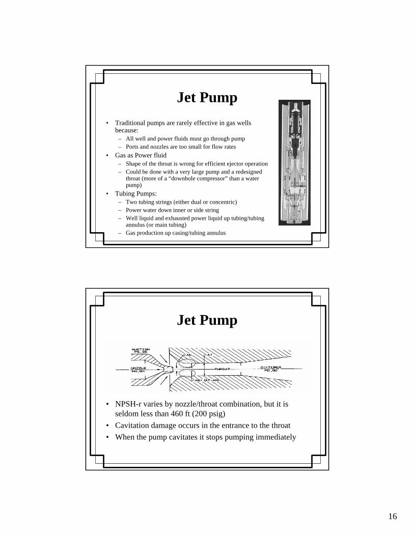
Jet Pump• Traditional pumps are rarely effective in gas wells
because:– All well and power fluids must go through pump– Ports and nozzles are too small for flow rates
• Gas as Power fluid– Shape of the throat is wrong for efficient ejector operation– Could be done with a very large pump and a redesigned
throat (more of a “downhole compressor” than a water pump)
• Tubing Pumps:– Two tubing strings (either dual or concentric)– Power water down inner or side string– Well liquid and exhausted power liquid up tubing/tubing
annulus (or main tubing)– Gas production up casing/tubing annulus
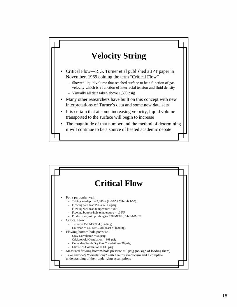
Jet Pump
• NPSH-r varies by nozzle/throat combination, but it is seldom less than 460 ft (200 psig)
• Cavitation damage occurs in the entrance to the throat• When the pump cavitates it stops pumping immediately

17
Surfactant• Soaps, foamers, and other surfactants are designed to foam
and:– Introduce voids that lighten the liquid column– Reduce the surface tension of the liquid drops to minimize their
size/weight
• All soaps have to be activated by agitation• Care must be exercised to ensure that the soaps are activated
downhole– Unactivated liquid soap will often activate and foam in the
production/measurement equipment– Foaming in the gathering system will tend to increase the condensation
surface and increase water problems– Liquid soap is “gummy” and can increase skin
Deliquification Techniques
• Velocity String• Tubing-flow controller• Plunger• Vortex tool• Evaporation
18
Velocity String
• Critical Flow—R.G. Turner et al published a JPT paper in November, 1969 coining the term “Critical Flow”– Showed liquid volume that reached surface to be a function of gas
velocity which is a function of interfacial tension and fluid density– Virtually all data taken above 1,300 psig
• Many other researchers have built on this concept with new interpretations of Turner’s data and some new data sets
• It is certain that at some increasing velocity, liquid volume transported to the surface will begin to increase
• The magnitude of that number and the method of determining it will continue to be a source of heated academic debate
Critical Flow• For a particular well:
– Tubing set-depth = 3,000 ft (2-3/8” 4.7 lbm/ft J-55)– Flowing wellhead Pressure = 4 psig– Flowing wellhead temperature = 80°F– Flowing bottom-hole temperature = 105°F– Production (just up tubing) = 130 MCF/d, 5 bbl/MMCF
• Critical Flow– Turner = 158 MSCF/d (loading)– Coleman = 132 MSCF/d (onset of loading)
• Flowing bottom-hole pressure– Gray Correlation = 55 psig– Orkiszewski Correlation = 308 psig– Cullender-Smith Dry Gas Correlation= 30 psig– Duns-Ros Correlation = 135 psig
• Measured flowing bottom-hole pressure = 8 psig (no sign of loading there)• Take anyone’s “correlations” with healthy skepticism and a complete
understanding of their underlying assumptions
19
Velocity String• A “velocity string” is a string of tubing that is intended to force normal gas
flow rate to have a velocity greater than the “critical velocity”• Higher velocity equates to higher friction drop• Wells with velocity strings are very unforgiving:
– If rate increases, friction will rapidly raise FBHP– If rate decreases slightly, you can drop below the actual critical rate and load
up– A cold section in the wellbore can condense water vapor and upset the balance
on a near-critical well– Aggressive velocity strings preclude both plungers and swabbing
• It is not a good idea to fully open the casing with a velocity string– Flow in the velocity string will drop to very near zero– The well is nearly assured of loading up and can be difficult to restart
Tubing-Flow Controller
• If you’re using a velocity string and the tubing/casing differential pressure is “excessive” then you can alleviate high friction drop by allowing some casing flow:– Must monitor tubing flow to make sure you stay above critical– Must throttle casing flow carefully to ensure that you don’t upset
the tubing flow too much
• Most installations use:– Orifice meter on the tubing– Pneumatic control valve on casing
• This rarely works probably due to: – Relatively large dP caused by the meter– Sluggishness of the pneumatic valve
20
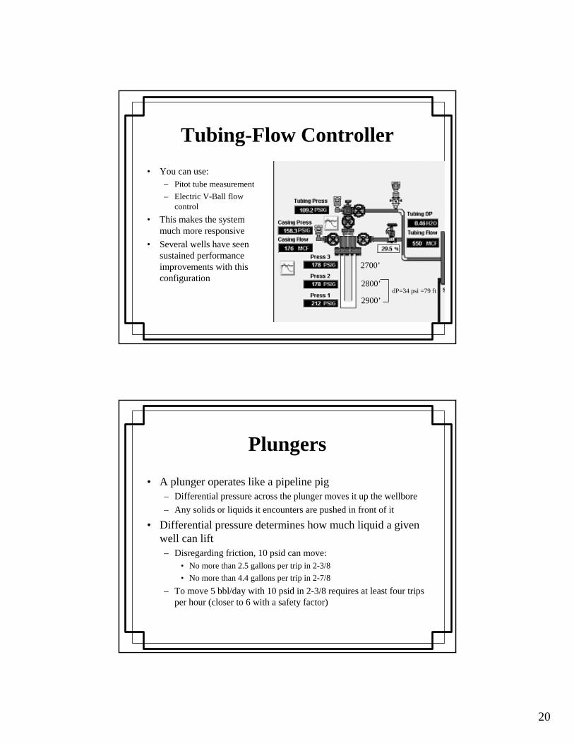
Tubing-Flow Controller• You can use:
– Pitot tube measurement– Electric V-Ball flow
control• This makes the system
much more responsive• Several wells have seen
sustained performance improvements with this configuration
2700’
2800’
2900’dP=34 psi =79 ft
Plungers
• A plunger operates like a pipeline pig– Differential pressure across the plunger moves it up the wellbore– Any solids or liquids it encounters are pushed in front of it
• Differential pressure determines how much liquid a given well can lift– Disregarding friction, 10 psid can move:
• No more than 2.5 gallons per trip in 2-3/8• No more than 4.4 gallons per trip in 2-7/8
– To move 5 bbl/day with 10 psid in 2-3/8 requires at least four trips per hour (closer to 6 with a safety factor)
21
Plungers
• The various types of plungers are differentiated by:– Fall rate– Quality of seal– Efforts to clean pipe
• There is a narrow window in reservoir pressure where plungers are the best choice:– Early in life, there tends to be enough FBHP that the well doesn’t
need assistance– Late in life the pressure required to lift a plunger plus a load of
water is greater than the pressure available
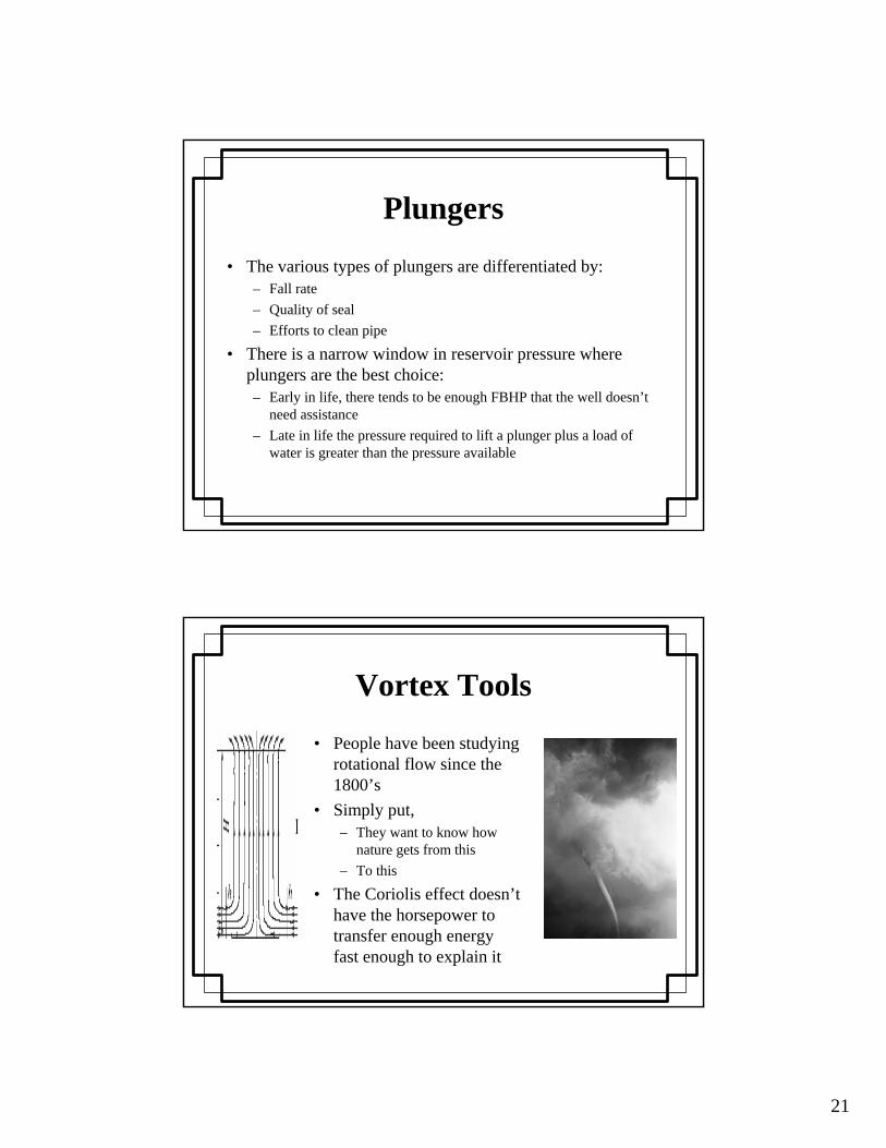
Vortex Tools
• People have been studying rotational flow since the 1800’s
• Simply put, – They want to know how
nature gets from this– To this
• The Coriolis effect doesn’t have the horsepower to transfer enough energy fast enough to explain it

22
Vortex Tools• Hurricanes last for weeks• Tornadoes last for hours• If a man-made vortex can be controlled to last
for 10-15 minutes it could be valuable– Typical critical velocity often 50 ft/sec– 10 minutes at 50 ft/sec = 30,000 ft
• Vortex tools have been shown to lower critical velocity by about 30%
• Vortex tools tend to sling liquids to the outside of the pipe while minimizing the gas/liquid interfacial tension
Evaporation• Whenever there is a coherent gas/liquid interface, liquid
will evaporate until the gas at the surface of the liquid is at 100% relative humidity
• Water vapor is not:– Fine spray (101-200 micron)– Mist (51-100 micron)– An aerosol (1-50 micron)
• A water vapor molecule is 0.00038 microns• Separator mist extractors are usually rated at about 20
microns• As wellhead pressures diminish, the amount of water that
gas can carry as “humidity” increases dramatically

23
Evaporation
Evaporation• At low pressures evaporation is often adequate by itself• If you are relying on evaporation, then critical flow is
irrelevant:– Water vapor will move as a gas– The gas doesn’t have to drag the water drops along– You want the gas to move as slowly as possible to minimize
friction– It can be a good idea to remove the tubing altogether
• Separators will not accumulate liquid except what condenses due to vessel temperature being lower than dew point
• The water will condense in the piping as distilled water
24
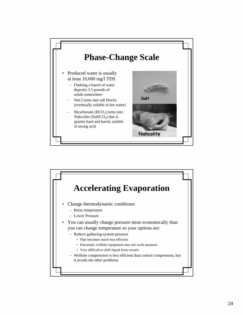
Phase-Change Scale
• Produced water is usually at least 10,000 mg/l TDS– Flashing a barrel of water
deposits 3.5 pounds of solids somewhere
– Bicarbonate (HCO3) turns into Nahcolite (NaHCO3) that is granite hard and barely soluble in strong acid
– NaCl turns into salt blocks (eventually soluble in hot water)
Nahcolite
Accelerating Evaporation
• Change thermodynamic conditions:– Raise temperature– Lower Pressure
• You can usually change pressure more economically than you can change temperature so your options are:– Reduce gathering-system pressure
• Pipe becomes much less efficient• Pneumatic wellsite equipment may not work anymore• Very difficult to shift liquid from vessels
– Wellsite compression is less efficient than central compression, but it avoids the other problems
25
Typical Wellsite Compressor Types
Control air5Disch temp60 - 72%Dry Screw
Vacuum to slight positive pressure
4-6Boiling point of liquid
50-60%Liquid Ring
4.5/stage
10-20
5/stage
Max Ratios
Typical UseLimitEff
Varying dischargeRod load or disch temp
78 - 88%Reciprocating
Varying suction Max suction Press
70 - 82%Flooded Screw
Plant Inlet (no oil in gas)
Disch temp65 - 75%Centrifugal
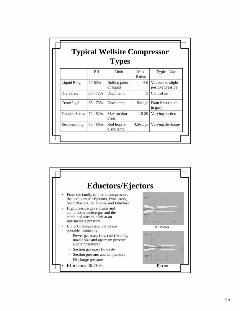
Eductors/Ejectors• From the family of thermocompressors
that includes Air Ejectors, Evacuators, Sand Blasters, Jet Pumps, and Eductors
• High pressure gas entrains and compresses suction gas and the combined stream is left at an intermediate pressure
• Up to 10 compression ratios are possible, limited by:– Power gas mass flow rate (fixed by
nozzle size and upstream pressure and temperature)
– Suction gas mass flow rate– Suction pressure and temperature– Discharge pressure
• Efficiency 40-70%
Jet Pump
Ejector
26
Eductor Application
• Everything sucks– Compressor sucks on
tubing/casing annulus– Eductor sucks on tubing to
maintain liquid level very near end of tubing
• Small amount of hp– 32 hp for power gas– 14 hp used in eductor– ε=44%
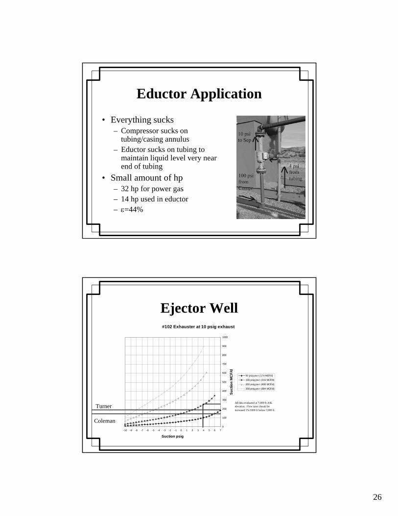
Ejector Well#102 Exhauster at 10 psig exhaust
0
100
200
300
400
500
600
700
800
900
1000
-10 -9 -8 -7 -6 -5 -4 -3 -2 -1 0 1 2 3 4 5 6 7
Suction psig
Suc
tion
MC
F/d
50 psig pw r (174 MCF/d)
100 psig pw r (316 MCF/d)
200 psig pw r (600 MCF/d)
300 psig pw r (884 MCF/d)
All data evaluated at 7,000 ft ASL elevation. Flow rates should be increased 1%/1000 ft below 7,000 ft.
Turner
Coleman
27
Conclusion
• Deliquification is different from Artificial Lift and it requires different:– Tools – Mind set– Staffing levels
• No technology is set-and-forget:– Be prepared for any given technology to work or fail to work on
any given well (regardless of “similar” wells in the same field)– Expect to spend considerable field and engineering effort to “get it
right” only to find that as pressures change it doesn’t work any more
• There is no “silver bullet” for deliquification