DELAYED STALL MODELLING OF THE ROTATING BLADES · 2011-05-24 · THE PUBLISHING HOUSE PROCEEDINGS...
9
THE PUBLISHING HOUSE PROCEEDINGS OF THE ROMANIAN ACADEMY, Series A, OF THE ROMANIAN ACADEMY Volume 12, Number 2/2002, pp. 100–108 DELAYED STALL MODELLING OF THE ROTATING BLADES Horia DUMITRESCU, Vladimir CARDOŞ “Gh. Mihoc-C. Iacob” Institute of Statistical Mathematics and Applied Mathematics, Bucharest, Romania E-mail: [email protected] Most aerodynamic design tools for horizontal-axial wind turbines are based on the blade-element momentum theory. Due to the nature of this theory, the design tools need 2-D steady sectional lift and drag curves as an input. In practice, flow over a wind turbine rotor blade is neither two-dimensional nor steady, and is affected by rotation. Pioneering experiments have identified a consequence: at inboard rotor blade sections stall is delayed. This so-called Himmmelskamp effect gives a larger lift than predicted and, as a result, a higher power and loading than expected. Consequently, an aerodynamic model is needed to explain and predict sectional lift and drag under rotating conditions. In this paper development and validation against the computed and measured results, of such a model is described. Key words: Three-dimensional boundary layer; Boundary layer separation; Rotational effects. 1. INTRODUCTION Wind turbine blade sections can operate with stall at low tip speed ratios and can undergo delayed stall [1], characterized by strong differences between the measured performances and predictions based on 2-D airfoil characteristics in stall conditions. Thus predicting blade loads and the power output during stall is fundamental to the improved design of the fixed-speed stall-regulated turbines. Modeling of delayed stall through the numerical solution of the Navier-Stokes equations with CFD techniques has shown some recent success [2–3] and has become increasingly feasible with the increase in computational power. CFD solutions are, however, still computationally very expensive and are basically prohibitive for the routine engineering analyses of wind turbines. In addition, there are numerous issues such as rotational turbulence modeling that still need to be understood. In the absence of less approximate and cost-effective solutions, researchers have used various semi-empirical models to represent stall-delay. The advantage of using these models is their relative simplicity and low computational expense. Nevertheless, no practically useful method for accurate predicting this phenomenon was generated. The present work aims at giving a clearer interpretation of the three-dimensional effects on the rotor blade sections in stall using the available numerical and experimental results. Then, the main contributions for the rise of the delayed stall phenomenon are discussed and assessed. 2. SURVEY OF PREVIOUS RESULTS The local air velocity relative to a rotor blade consists of free-wind velocity V w defined as the wind speed if there were no rotor present, that due to the blade motion Ω b r and the wake induced velocities (not important for present analysis). Wind turbine blade sections can operate in two main regimes depending on the amount of rotation parameter defined as the ratio of wind velocity to the local tangential velocity r V b w Ω / . If the rotation parameter is less than unity along the entire span the flow is mostly two- dimensional and attached, while for rotation parameter greater than unity the flow is neither two-dimensional nor steady, and is affected by rotation. Here, the inboard flow with enhanced rotation produces, along the suction side of the rotor blade sections, a leading edge separation bubble which remains attached through high angles of attack.
Transcript of DELAYED STALL MODELLING OF THE ROTATING BLADES · 2011-05-24 · THE PUBLISHING HOUSE PROCEEDINGS...

THE PUBLISHING HOUSE PROCEEDINGS OF THE ROMANIAN ACADEMY, Series A, OF THE ROMANIAN ACADEMY Volume 12, Number 2/2002, pp. 100–108
DELAYED STALL MODELLING OF THE ROTATING BLADES
Horia DUMITRESCU, Vladimir CARDOŞ
“Gh. Mihoc-C. Iacob” Institute of Statistical Mathematics and Applied Mathematics, Bucharest, Romania E-mail: [email protected]
Most aerodynamic design tools for horizontal-axial wind turbines are based on the blade-element momentum theory. Due to the nature of this theory, the design tools need 2-D steady sectional lift and drag curves as an input. In practice, flow over a wind turbine rotor blade is neither two-dimensional nor steady, and is affected by rotation. Pioneering experiments have identified a consequence: at inboard rotor blade sections stall is delayed. This so-called Himmmelskamp effect gives a larger lift than predicted and, as a result, a higher power and loading than expected. Consequently, an aerodynamic model is needed to explain and predict sectional lift and drag under rotating conditions. In this paper development and validation against the computed and measured results, of such a model is described.
Key words: Three-dimensional boundary layer; Boundary layer separation; Rotational effects.
1. INTRODUCTION
Wind turbine blade sections can operate with stall at low tip speed ratios and can undergo delayed stall [1], characterized by strong differences between the measured performances and predictions based on 2-D airfoil characteristics in stall conditions. Thus predicting blade loads and the power output during stall is fundamental to the improved design of the fixed-speed stall-regulated turbines.
Modeling of delayed stall through the numerical solution of the Navier-Stokes equations with CFD techniques has shown some recent success [2–3] and has become increasingly feasible with the increase in computational power. CFD solutions are, however, still computationally very expensive and are basically prohibitive for the routine engineering analyses of wind turbines. In addition, there are numerous issues such as rotational turbulence modeling that still need to be understood. In the absence of less approximate and cost-effective solutions, researchers have used various semi-empirical models to represent stall-delay. The advantage of using these models is their relative simplicity and low computational expense. Nevertheless, no practically useful method for accurate predicting this phenomenon was generated.
The present work aims at giving a clearer interpretation of the three-dimensional effects on the rotor blade sections in stall using the available numerical and experimental results. Then, the main contributions for the rise of the delayed stall phenomenon are discussed and assessed.
2. SURVEY OF PREVIOUS RESULTS
The local air velocity relative to a rotor blade consists of free-wind velocity Vw defined as the wind speed if there were no rotor present, that due to the blade motion Ωbr and the wake induced velocities (not important for present analysis). Wind turbine blade sections can operate in two main regimes depending on the amount of rotation parameter defined as the ratio of wind velocity to the local tangential velocity
rV bw Ω/ . If the rotation parameter is less than unity along the entire span the flow is mostly two-dimensional and attached, while for rotation parameter greater than unity the flow is neither two-dimensional nor steady, and is affected by rotation. Here, the inboard flow with enhanced rotation produces, along the suction side of the rotor blade sections, a leading edge separation bubble which remains attached through high angles of attack.

2 Delayed stall modeling of the rotating blades 101
For the prior stall regime 1/ ≤Ω rV bw , the relative velocity at a specific position on the blade is written as
( ) 2/1222 rVU bwrel Ω+= , (1)
where the effective incoming flow velocity is simply composed of the free-flow velocity and the induction velocity from rotor. Therefore, the incoming flow field results from a weak interaction between two different flows: one axial and other rotational.
The theoretical description of the flow of air is based on the potential flow model that complies with the radial independence principle of flow effects, i.e. the radial component of velocity is dependent only upon the 2-D velocity potential and it is independent of the span. In the prior-stall state the following findings are important for the understanding of the flow effects in the sequel:
• the main parameter of influence of the weak interaction flow is the radius by local chord ratio r/c;
• the shape of the chordwise pressure coefficient distribution normalized by the maximum pressure coefficient pmC and the corresponding pressure gradients along the upper surface are not
really affected by r/c, i.e. the pressure parameter pmC is dependent only the airfoil shape, incidence
and Reynolds number [4, 5]; • the suction side distribution of the pressure coefficients moves slightly towards lower levels
as r/c decreases [4, 5]; • the separation point location moves slightly downstream towards the trailing edge as r/c
decreases [4, 5]; • the Coriolis force induced in the chordwise direction by rotation is the main contribution of
the favorable effect in separation delaying, resulting in slight lift increasing, [4, 5]. These features that are attributable to rotation usually are neglected in the traditional BEM model, with
lift and drag forces determined from 2-D measurements. The model reduces the complexity of the problem by an order of magnitude yielding reliable results for the local forces and the overall torque in the proximity of the design point, at high tip speed ratios. But, the wind turbine blade sections often operate with stall at low tip speed ratios and can undergo delayed stall phenomenon on the inner part of span. As the wind velocity increases the inboard regions of the blades are stalled having 1/ >Ω rV bw for much of their operational time. Thus predicting blade loads and the power output during stall is fundamental to the improved design of wind turbines.
The post-stall regime is characterized by a strong nonlinear interaction between the high wind speed and the rotational flow induced by a constant-speed rotor and now the relative velocity can be written as
1/ 22
2 2 1 ,w wrel b f
b b
V VrU r rr c r
= Ω + = Ω Ω Ω
, (2)
a form that suggests an outer rotational flow with angular velocity higher than that of the constant-speed rotor.
Numerical and experimental studies [2–3, 6], have been directed towards understanding the complex 3-D flow physics that are associated with the post-stall region. Nevertheless, little detailed information concerning the understanding the basic fluid mechanics of inboard stall-delay is still rather unclear. Some features associated with the flow physics responsible for rotational stall delay come from [7]. These recent findings are consistent with the numerical studies [2, 3] and they can be summarized as follows:
• two non-dimensional parameters rV bw Ω/ and r/c are important for further understanding of the strong interaction flow;
• at high wind velocities the suction side of the inner half-rotor behaves like a disk rotating slower than the outer flow, fb Ω<Ω [7];
• the enhanced rotational outer flow acts at the root area of the blade as a vortex that produces a sucking effect and radial mass flux towards the rotation center;

Horia Dumitrescu, Vladimir Cardoş 3 102
• the pressure coefficient distributions are gradually smoothed, as rV bw Ω/ increases and the pressure coefficient with no suction spike moves rapidly towards pressure distributions with no suction spike at leading edge;
• at high angles of attack the sucking effect produces leading edge separation bubbles, attached, instead of the usual leading edge separation (stall), resulting mainly in stall delaying and higher lift and drag as compared with 2-D stall.
A theoretical description of the strong interaction flow must be able to capture both the enhanced rotational flow effect and the high-lift effect of the airfoils at high angle of attack. Also, an important result is that the midspan rapid lift-drag rise governs the peak power of rotor, but the sequence of these aerodynamic events as yet is not well understood.
3. MODELLING OF 3-D AND ROTATIONAL EFFECTS
Fig. 1 − Boundary layer on a rotating disk slower than the outer flow (vortex-induced sucking effect).
Boundary layer on a finite disk (in a faster rotating flow). The rotating disk in an axial flow is a generalization of the rotating disk case which depends not only the number Reynolds νΩ= /Re 2
dd R , but also on the rotation parameter dd RV Ω∞ / . The strong nonlinear interaction between the rotating outer flow and the boundary layer developing on the disk produces a radial inflow accompanied by an axial inflow near the edge of the disk and an axial outflow in the central core (Fig. 1). In order to analysis the enhanced rotation by high axial velocities (strong winds) consider the axisymmetric laminar rotating flow of a viscous incompressible fluid over a disk of radius Rd (Fig. 1). The angular velocity of the disk Ωd is constant and that of the fluid far away from the disk Ωf may be an arbitrary function of the radius r, provided it is stable, i.e. ( )2d / d 0f r rΩ > (for potential vortex rotation 2 const.f rΩ = ) and near the axis the outer flow behaves locally
like a rigid body rotation, i.e. 00 : d / d 0,f f fr r→ Ω → Ω →Ω (finite). The fluid is assumed to be an ideal gas with constant properties and zero bulk viscosity and the flow is laminar. We use the following nondimensional quantities defined for an inertial system of cylindrical coordinates: ( ) ( ) ( ) ( ) ( ), , / , , , , , /d d d d fr z r z R u v w u v w R= = Ω Ω < Ω . The equation of state is p/ρ = const. The
nondimensional parameter of the flow field is the Ekman number, 2d
ERν
=Ω
, where µν =
ρ is the kinematical
viscosity. It is also assumed that the Ekman number is small enough so that boundary layer approximations are valid and the boundary layer equations write as
( ) ( )
0ru rwr z
∂ ∂+ =
∂ ∂, (3)

4 Delayed stall modeling of the rotating blades 103
( ) ( )2 2 2 2
2
1u uw pu v ur r z r z
∂ ∂ ∂− ∂+ + = − + ν
∂ ∂ ρ ∂ ∂, (4)
( ) ( ) 2
2
2uv vwuv vr r z z
∂ ∂ ∂+ + = ν
∂ ∂ ∂, (5)
with 0pz∂
=∂
.
The boundary conditions at the surface of the disk are 0 : 0, dz u w v r= = = = Ω . The conditions at the edge of the boundary layer and the pressure distribution are given by the outer flow, for which we assume that the radial velocity is negligible and the azimuthally velocity is a function of radius only. The outer flow
radial momentum equation is then 2 d1dfprr
Ω =ρ
and the pressure in the outer flow is
( ) ( ) 2 d
dRd
fr
p R p rp r r−∆
= = Ωρ ρ ∫ . (6)
The conditions at the edge of the boundary layer thus read: : 0, fvz urΩ= δ = Ω = = Ω .
Now, we define a boundary coordinate 1/ 2 /zE−Ωη = δ based on the boundary layer thickness
( ) 1 / 2Er EΩδ = δ and assume radial and angular velocity profiles which satisfy the boundary conditions at the
disk surface and the smoothness requirements at the edge of the boundary layer:
( ) ( ) ( ) ( ) ( )' , ' 0 0, ' 1 0, " 1 0u U r f f f f= η = = = , (7)
( ) ( ) ( ) ( ), 0 0, 1 1, ' 1 0d
f d
g g g gΩ−Ω
= η = = =Ω −Ω
. (8)
The radial mass flux in the boundary layer is
( ) ( )1/ 2
0
d 1E
Eq ru zE r EUfδ
−= ρ = ρ δ∫ . (9)
Integrating (3)–(5) with the profiles (7), (8), and using the nondimensional quantities we have the radial and azimuthally momentum integral equations for two unknowns: the radial mass flow ( )rq and the boundary layer thickness ( )rEδ
( ) ( ) ( ) ( )1 1 11 1
1
d 1 12d 1 1 1 1d d
ff f f
E
c rqq qr r r
Ω − λ − λ Ω − − λ − λ Ω − + = Ω − λ δ , (10)
( ) ( )2 2
2 22 2 3 42 3 2
d 1 1d E f f
E E E
c qq q rr r r r λ + λ + δ λ Ω − + λ Ω − = − δ δ δ
. (11)
Here /f f dΩ = Ω Ω and the parameters 1 2 3 4 1 2, , , , ,c cλ λ λ λ are forms parameters[7]. Boundary layer an rotating blades. There are two rules that synthesize to a great extent the results
known so far. The first rule states that: “The chordwise pressure coefficient distribution along the upper surface and normalized by its maximum value is not dependent on the ratio r/c in prior-stall flow”. The second rule which governs the post-stall flow states that: “The normalized chordwise pressure coefficient distribution on the upper surface at a given inboard location is strongly dependent on the parameter
rV bw Ω/ , but preserves the integrated coefficient until the inboard separation bubble is broken down and the flow is stalled”. In other words, the lift coefficient on the blade section at high angle of attack can be found
Horia Dumitrescu, Vladimir Cardoş 5 104
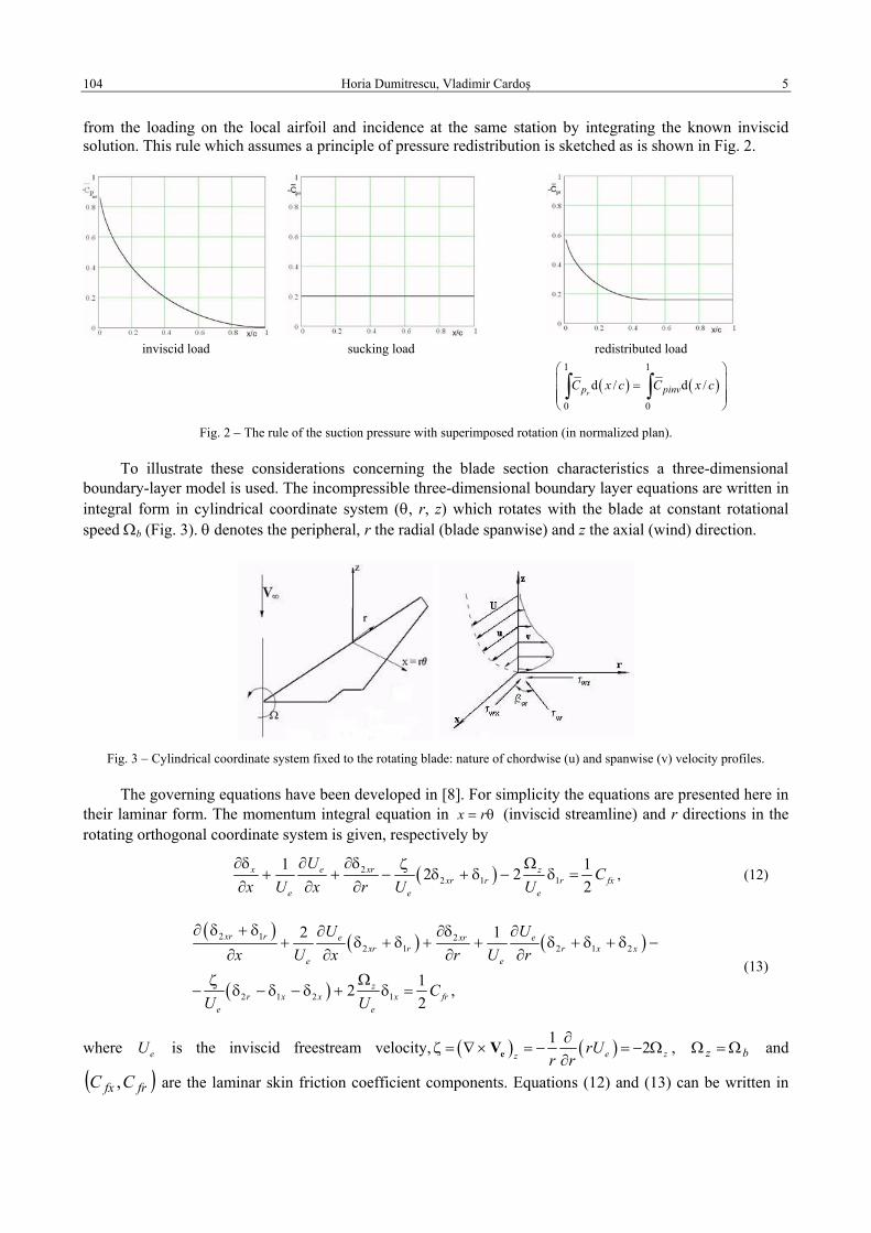
from the loading on the local airfoil and incidence at the same station by integrating the known inviscid solution. This rule which assumes a principle of pressure redistribution is sketched as is shown in Fig. 2.
inviscid load sucking load redistributed load
( ) ( )1 1
0 0
d / d /rp pinvC x c C x c
= ∫ ∫
Fig. 2 − The rule of the suction pressure with superimposed rotation (in normalized plan).
To illustrate these considerations concerning the blade section characteristics a three-dimensional boundary-layer model is used. The incompressible three-dimensional boundary layer equations are written in integral form in cylindrical coordinate system (θ, r, z) which rotates with the blade at constant rotational speed Ωb (Fig. 3). θ denotes the peripheral, r the radial (blade spanwise) and z the axial (wind) direction.
Fig. 3 − Cylindrical coordinate system fixed to the rotating blade: nature of chordwise (u) and spanwise (v) velocity profiles.
The governing equations have been developed in [8]. For simplicity the equations are presented here in their laminar form. The momentum integral equation in x r= θ (inviscid streamline) and r directions in the rotating orthogonal coordinate system is given, respectively by
( )22 1 1
1 12 22
x e xr zxr r r fx
e e e
UC
x U x r U U∂δ ∂ ∂δ Ωζ
+ + − δ + δ − δ =∂ ∂ ∂
, (12)
( ) ( ) ( )
( )
2 1 22 1 2 1 2
2 1 2 1
2 1
12 ,2
xr r e xr exr r r x x
e e
zr x x x fr
e e
U Ux U x r U r
CU U
∂ δ + δ ∂ ∂δ ∂+ δ + δ + + δ + δ + δ −
∂ ∂ ∂ ∂Ωζ
− δ − δ − δ + δ = (13)
where eU is the inviscid freestream velocity, ( ) ( )1 2e zz rUr r∂
ζ = ∇× = − = − Ω∂eV , bz Ω=Ω and
( )frfx CC , are the laminar skin friction coefficient components. Equations (12) and (13) can be written in

6 Delayed stall modeling of the rotating blades 105
terms of the three parameters: the boundary layer thickness 2δν
, the Pohlhausen shape parameter
xU e
∂∂
νδ
=Λ2
, and the limiting streamline parameter wε [8].
The inviscid flow distribution along the upper surface of the blade needed to complete the above boundary-layer description is given according to the radial independence principle
0,2 ≅= eDre VUUU , (14)
where ( ) 2/1222 rVU bwr Ω+= is the reference velocity at a point on blade and the nondimensional velocity
pD CU −= 12 depends only on the local aerodynamic field at a certain radial station. The aerodynamic
loading over the chord Cp is prescribed by means of an one-parameter distribution family
−
−= 12
cx
cxCC
mpp , (15)
where the maximum pressure coefficient mpC is a parameter depending only on the local aerodynamic
field: the airfoil shape, incidence and Reynolds number. This pressure distribution family ranges a large area from the prior-stall pressure distributions, values of
mpC = 2 – 5, until the post-stall pressure distributions
with mpC = 6 – 10.
Since the primary objective of the present study is to investigate the sucking effect of the leading-edge suction pressure on the boundary-layer separation, the proposed distribution (15) is an excellent demonstrator for the physical mechanism of the operation in the stalled inboard regions of the blades.
4. NUMERICAL RESULTS
a b
Fig. 4 − Sucking characteristics for a disk rotating slower than the outer flow: a) mass flow rate; b) sucking pressure.

Horia Dumitrescu, Vladimir Cardoş 7 106
The results obtained by numerical integration of (10) and (11) with variable fΩ for the outer Rankine
vortex flow and various parameters dd
w
RV
Ω or
λ1 are presented in Fig. 4, where the pressure coefficient
shown is defined as
( )222/ rVpC
dps Ω+ρ
∆−=
∞
, (16)
or in normalized plan hss ppp CCC /= , where
hpC is the reference pressure on the hub of the rotor.
a b
Fig. 5 − Influence of the r/c ratio on the pressure and the separation point location (SP) for 1w
b
Vr<
Ω: a) normalized plan;
b) physical plan ( 5mpC = ).
Figure 5 illustrates the rule governing the flow field around the airfoils in the prior-stall running ( )5.2>λ and the contribution of Coriolis force to the delay in boundary layer separating. The relationships
between the maximum pressure coefficient mpC and the separation position (x/c)s in terms of the ratio r/c
are shown in both normalized and physical plan. The Coriolis force acts in the chordwise direction as a favorable pressure gradient resulting in slightly increasing of
mpC and (x/c)s as r/c decreases.
The second rule governing the post-stall running
≥
Ω≤λ 1 and 5.2
rV
b
w is better understood
considering Fig. 6 where the redistributed suction pressure coefficient rpC , and the separation/reattachment
position, ( ) ( )rs cxcx /// , are plotted against the sucking pressure coefficient spC for
mpC =10 and r/c = 2.
Increasing the air sucking along the suction side of the airfoil one notes considerable changes between the leading edge region with a sharp suction peak, and the region with smooth pressure variations over the chord showing a flattening of the pressure distribution with practically no suction surface pressure gradient.

8 Delayed stall modeling of the rotating blades 107
Fig. 6 − Influence of the spC sucking effect on the pressure distribution for 1w
b
Vr>
Ω: a) normalized plan;
b) physical plan ( 10, / 2mpC r c= = ).
The comparisons of measured [6], computed [2, 3] and modeled pressure distributions are shown for the higher wind speeds (15 (λ=2.5), 20 (λ=1.9) and 25 (λ=1.5) m/s) at the spanwise section r/R = 0.30 (r/c = 2) that correspond to 215.02.0 −=
spC (Fig. 6b). The stall-delay behaviour and its explanation is well captured. The spanwise section r/R = 0.47 (r/c ≅ 4)
which is stalled for these cases shows a surprisingly good agreement with the assumption ( ) 1/ 1br R −≅ + λ for the location of the bubble burst. Furthermore, the representation from Fig. 6a shows a physical limitation in the amount of the possible pressure in the sucking effect so that pressure distributions for r/c = 2 have no
suction surface pressure gradient ( ) ( )1 1
,0 0
d / d / 0.215spinv p bC x c C x c= =∫ ∫ .Still, these pressure distributions
attain Cp maximum of −2.15 that remains virtually constant for any sucking increase [6].
4. CONCLUSIONS
Using concepts of boundary layer theory we have studied the chordwise velocity boundary-layer superimposed with the radial angular velocity (Ekman) boundary-layer which occurs at the high wind-speed flow. The major conclusions are follows:
1. The rotational flow over the suction surface of the rotor, which is characterized by the rotation parameter rV bw Ω/ , has an important effect upon the boundary-layer state and the flow field structure on the wind turbine blade surface. For less than unity values rV bw Ω/ <1 the prior-stall flow (high tip speed ratios) remains largely attached to the surface of the blade. In contrast, for grater than unity values rV bw Ω/ >1 (low tip speed ratios) the post-stall flow along most of the span occurs associated with separation on the suction surface of the blade.
2. The post-stall flow manifests itself through inboard delayed stall with leading-edge separation bubbles and outboard stall aft the bubble burst. The flow aft of the separation line is largely in the radial direction, towards the tip of the blade. The interface flow between the inboard delayed stall-flow and the outboard stall-flow is associated with the bubble burst which is generally located at midspan. A better approximation is proposed by the empirical formula ( ) 11/ −λ+≅Rrb .

Horia Dumitrescu, Vladimir Cardoş 9 108
3. Two main contributions can be equally attributed to the rise of the stall-delay phenomenon: one is the speedy rotational flow induced at the hub which produces a sucking effect, resulting in suction pressure reducing/smoothing at the leading-edge, and the other one is the Coriolis force which acts in the chordwise direction as a favorable pressure gradient tending to the alleviate separation downstream towards the trailing edge. Concerning the centrifugal forces this effect known as pumping effect is largely produced aft of the bubble burst resulting in spanwise flow.
REFERENCES
1. TANGLER, J. L., Insight into wind turbine stall and post-stall aerodynamics, Wind Energy 7, pp. 247–260, 2004. 2. SØRENSEN, N. N., MICHELSEN, J. A., SCHRECK, S., Navier-Stokes predictions of the NREL PhaseVI Rotor, in the NASA
Ames 80 ft×120 ft wind tunnel, Wind Energy 5, pp. 151–169, 2002. 3. FLETCHER, T. M., BROWN, R. E., KIM, D. H., KWON, O. J., Predicting wind turbine blade loads using vorticity transport and
RANS methodologies, European Wind Energy Conference & Exhibition, Parc Channot, Marseille, France, 1–10, 2009. 4. CHAVIAROPOULOS, P. K., HANSEN, M. O. L., Investigating three-dimensional and rotational effects on wind turbine blades
by means of a quasi-3-D Navier-Stokes solver, Journal of Fluids Engineering, 122, pp. 330–336, 2000. 5. SHEN, W. Z., SØRENSEN, J. N., Quasi-3-D Navier-Stokes model for rotating airfoil, Journal of Computational Physics, 150,
pp. 518–548, 1999. 6. SCHRECK, S., ROBINSON, M., Rotational augmentation of horizontal axis wind turbine blade aerodynamic response, Wind
Energy 5, pp. 133–150, 2002. 7. DUMITRESCU, H., CARDOŞ, V., Inboard stall delay for wind turbine blades, European Wind Energy Conference & Exhibition,
16-19 March, Parc Chanot, Marseille, 2009. 8. DUMITRESCU, H., CARDOŞ, V., Inboard boundary layer state on wind turbine blades, ZAMM, 89, 3, pp. 163–173, 2009.
Received November 1, 2010