del-Driven Architecture for Agent-Based Systems - NASA · Mo del-Driven Architecture for...
13
Mo del-Driven Architecture for Agent-Based Systems Denis GraEanin' , H. Lally Singhl, Shawn A. Bohner', and Michael G. Hinchey2 Department of Computer Science Virginia Polytechnic Institute and State University, Blacksburg, VA 24061, USA {gracanin,lally,sbohner}Qvt . edu Michael.G.HincheyQnasa.gov NASA Goddard Space Flight Center, Greenbelt, MD 20771, USA Abstract. The Model Driven Architecture (MDA) approach uses a platform- independent model to define system functionality, or requirements, us- ing some specification language. The requirements are then translated to a platform-specific model for implementation. An agent architecture based on the human cognitive model of planning, the Cognitive Agent Architecture (Cougaar) is selected for the implementation platform. The resulting Cougaar MDA prescribes certain kinds of models to be used, how those models may be prepared and the relationships of the different kinds of models. Using the existing Cougaar architecture, the level of application composition is elevated from individual components to dc- main level model specifications in order to generate software artifacts. The software artifacts generation is based on a metarnodel. Each compc- nent maps to a UML structured component which is then converted into multiple artifacts: Cougaar/Java code, documentation, and test cases. 1 Introduction Agent-based systems provide a foundation for development of large scale applica- tions like logistics management, battlefield management, supply-chain manage- ment, to mention some. An example of agent-based systems is Cougaar (Cog- nitive Agent Architecture). Cougaar provides a software architecture for dis- tributed agent-based applications in domains characterized by hierarchical de- composition, tracking of complex tasks, generation and maintenance of dynamic plans [I, 21. The ability develop very complex applications comes with a price. It takes a lot of effort and learning in order to have complete understanding and ability to effectively use such agent-based systems. A domain expert must closely col- laborate with the developer in order to fully utilize an agent-based system for a particular domain. It is very unlikely that a domain expert will have sufficient understanding of the underlying agent-based system. A Model Driven Architecture (MDA) based approach can be used to au- tomatically generate software artifacts and to significantly simplify application https://ntrs.nasa.gov/search.jsp?R=20050137712 2019-02-07T15:34:57+00:00Z
Transcript of del-Driven Architecture for Agent-Based Systems - NASA · Mo del-Driven Architecture for...
Mo del-Driven Architecture for Agent-Based Systems
Denis GraEanin' , H. Lally Singhl, Shawn A. Bohner', and Michael G. Hinchey2
Department of Computer Science Virginia Polytechnic Institute and State University, Blacksburg, VA 24061, USA
{gracanin,lally,sbohner}Qvt . edu
Michael.G.HincheyQnasa.gov NASA Goddard Space Flight Center, Greenbelt, MD 20771, USA
Abstract. The Model Driven Architecture (MDA) approach uses a platform- independent model to define system functionality, or requirements, us- ing some specification language. The requirements are then translated to a platform-specific model for implementation. An agent architecture based on the human cognitive model of planning, the Cognitive Agent Architecture (Cougaar) is selected for the implementation platform. The resulting Cougaar MDA prescribes certain kinds of models to be used, how those models may be prepared and the relationships of the different kinds of models. Using the existing Cougaar architecture, the level of application composition is elevated from individual components to dc- main level model specifications in order to generate software artifacts. The software artifacts generation is based on a metarnodel. Each compc- nent maps to a UML structured component which is then converted into multiple artifacts: Cougaar/Java code, documentation, and test cases.
1 Introduction
Agent-based systems provide a foundation for development of large scale applica- tions like logistics management, battlefield management, supply-chain manage- ment, to mention some. An example of agent-based systems is Cougaar (Cog- nitive Agent Architecture). Cougaar provides a software architecture for dis- tributed agent-based applications in domains characterized by hierarchical de- composition, tracking of complex tasks, generation and maintenance of dynamic plans [I, 21.
The ability develop very complex applications comes with a price. It takes a lot of effort and learning in order to have complete understanding and ability to effectively use such agent-based systems. A domain expert must closely col- laborate with the developer in order to fully utilize an agent-based system for a particular domain. It is very unlikely that a domain expert will have sufficient understanding of the underlying agent-based system.
A Model Driven Architecture (MDA) based approach can be used to au- tomatically generate software artifacts and to significantly simplify application
https://ntrs.nasa.gov/search.jsp?R=20050137712 2019-02-07T15:34:57+00:00Z
2
development [3,4, ?]. The domain expert can specify requirements in a familiar, platform-independent format that hides platform-specific details.
The MDA approach can be used for developing applications using the Cougaar agent-based architecture. Cougaar components can be composed into a General Cougaar Application Model (GCAM) and develop a General Domain Applica- tion Model (GDAM) for specifying and automatically generating software appli- cations. This approach is discussed in the paper.
The remainder of the paper is organized as follows. Section 2 briefly describes Cougaar and its capabilities. Section 3 describes the use of the MDA approach for Cougar-based applications. Section 4 discusses the Cougaar-based MDd model while Section 5 describes the implementation. Section 6 concludes the paper.
2 Cougaar Agent-Based System
Cougaar is a “largescale workflow en,$ne built on a component-based distrib- uted agent architecture” [l]. It is deployed as a society of agents, which commu- nicate and work together to solve a problem. A Cougaar society is a set of agents running on one or more interconnected computers, all working together to solve a common class of problems. The problem may be partitioned into subproblems, in which case the responsible subset of agents is called a community. A society may have one or more communities within.
The relationship between societies, communities, and agents is not a strict one, a society may directly contain both agents and communities. While a society has a red-world representation, a set of computers running a Cougaar system, a community is only notational in nature.
A Cougaar agent is a first-class- member of a Cougaar Society [l] and it contains a Blackboard and one or more Plu,&s While the specific purpose of any agent is chosen by the system developer; the objective is €or a single agent to represent a single organizational entity or a part thereof.
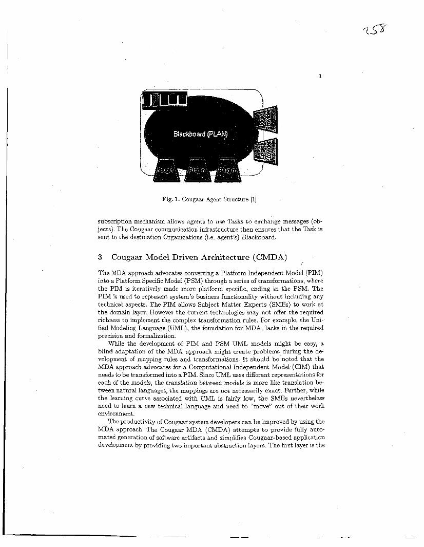
At the most basic level, an agent consists of two parts: a Blackboard and a set of Plu,o;ins (Fibwe 1). The former is a container of objects, with a subscription- based change notification mechanism; the latter is a set of responders to these notifications, with the ability to change the contents of the Blackboard.
The Blackboard serves as the communications backbone connecting the Plu- gins together. More importantiy, it serves as the eutij- pok t f ~ r zq iricsecg messages to the agent as a whole, which are then picked up by the Plughi for handling. All instancespecific behavior of the agent is implemented within the Plugin. A Plugin listens to add, remove, and change events on the Blackboard. Evaluating the objects invoived in the event, the Phigh may respmd by per- forming some computation, changes to the Blackboard, or some external work.
A Cougaar Node conceptually encapsulates a set of agents. Agents can collab- orate with other agents in the same Node or with agents in other Nodes. However, it is not a direct collaboration. Instead, Cougaar Tasks are allocated to Cougaar Organizations, which are representations of agents in the local Blackboard. The
3
Fig. 1. Cougaar Agent Structure [l]
subscription mechanism allows agents to use Tasks to exchange messages (ob- jects). The Cougaar communication infrastructure then ensures that the Task is sent to the destination Organizations (i.e. agent’s) Blackboard.
3
The MDA approach advocates converting a Platform Independent Model (PIM) into a Platform Specific Model (PSM) through a series of transformations, where the PIM is iteratively made more platform specific, ending in the PSM. The PIM is used to represent system’s business functionality without including any technical aspects. The PIM allows Subject Matter Experts (SMEs) to work at the domain layer. However the current technologies may not offer the required richness to implement the complex transformation rules. For example, the Uni- fied Modeling Language (UML), the foundation for MDA, lacks in the required precision and formalization.
While the development of PIM and PSM UML models might be easy, a blind adaptation of the MDA approach might create problems% during the de- velopment of mapping rules and transformations. It should be noted that the MDA approach advocates for a Computational Independent Model (CIM) that needs to be transformed into a PIM. Since UML uses different representations for each of the models, the translation between models is more like translation be- tween natural languages, the mappings are not necessarily exact. Further, while the learning curve associated with UML is fairly low, the SMEs nevertheless need to learn a new technical language and need to “move” out of their work environment.
The productivity of Cougaar system developers can be improved by using the MDA approach. The Cougaar MDA (CMDA) attempts t o provide fully auto- mated generation of software artifacts and simplifies Cougaar-based application development by providing two important abstraction layers. The first layer is the
Cougaar Model Driven Architecture (CMDA) i
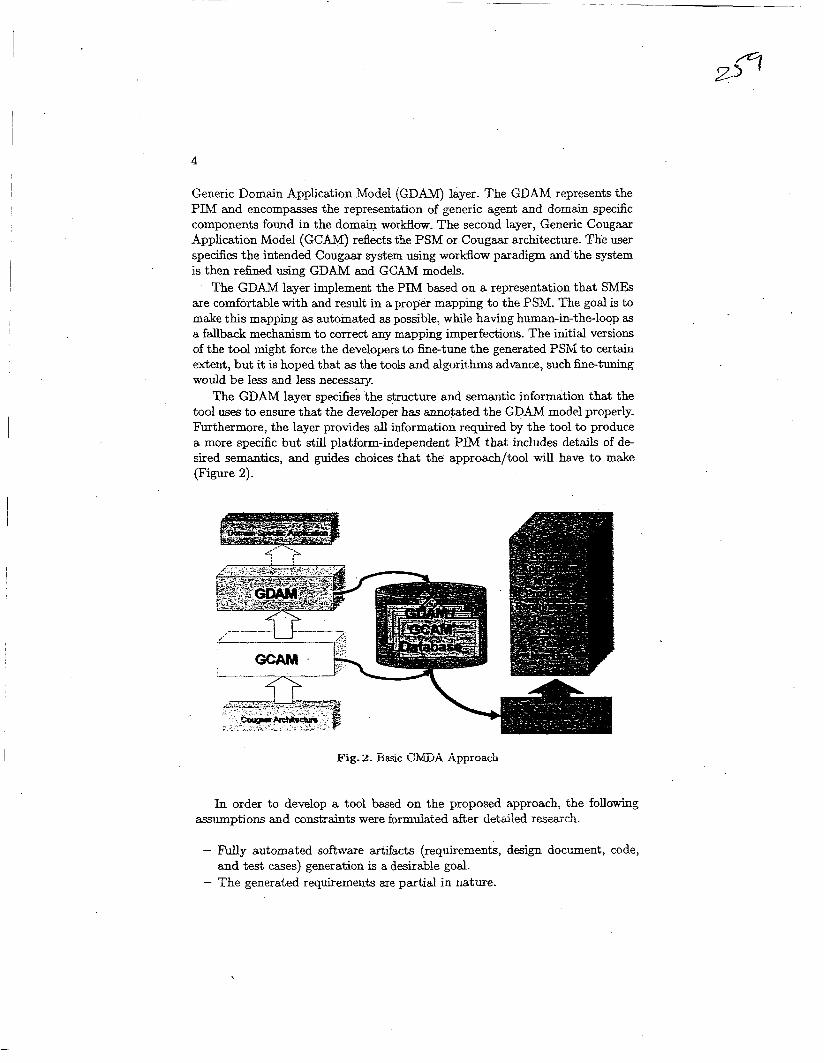
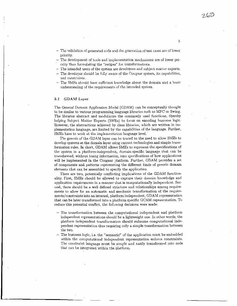
I Generic Domain Application Model (GDAM) layer. The GDAM represents the PIM and encompasses the representation of generic agent and domain specific components found in the domain workflow. The second layer, Generic Cougaar Application Model (GCAM) reflects the PSM or Cougaar architecture. The user specilies the intended Cougaa~ system using workflow paradigm and the system is then refined using GDAM and GCAM models.
The GDAM layer implement the PIM based on a representation that SMEk are comfortable with and result in a proper mapping to the PSM. The goal is to make this mapping as automated as possible, while having human-in-the-loop as a fallback mechanism to correct any mapping imperfections. The initial versions of the tool might force the developers to finetune the generated PSM to certain extent, but it is hoped that as the tools and algorithms advance, such hetuning would be less and less necessary.
The GDAM layer specif& the structure and semantic information that the tool uses to ensure that the developer has annotated the GDAM model properly. Furthermore, the layer provides all information required by the tool to produce a more speciiic but still platform-independent PIM that includes details of d e sired semantics, and ,@des choices that the approach/tool will have to make (Figure 2).
'
. . I .
Fig. 2. Basic CiviijA Approach
In order to develop a tool based on the proposed approach, the following assumptions and constraints were formulated after detailed resear&.
- Fully automated software artifacts (requirements, design document, code,
- The generated requirements are partial in nature. and test cases) generation is a desirable god.
The validation of generated code and the generation of test cases are of lower priority. The development of tools and implementation mechanisms are of lower pri- ority than formulating the “recipes” for transformations. The intended users of the system are developers and subject matter experts. The developer should be fully aware of the Cougaar system, its capabilities, and constraints. The SMEs should have sufficient knowledge about the domain and a basic understanding of the requirements of the intended system.
3.1 GDAM Layer
The General Domain Application Model (GDAM) can be conceptually thought to be similar to various programming language libraries such as MFC or Swing. The libraries abstract and modularize the commonly used functions, thereby helping Subject Matter Experts (SMEs) to focus on encoding business logic. However, the abstractions achieved by class libraries, which are written in im- plementation language, are limited by the capabilities of the language. Further, SMEs have to work at the implementation language level.
The genesis of the GDAM layer can be traced to the need to allow SMEs to develop systems at the domain layer using current technologies and simple trans- formation rules. In short, GDAM allows SMEs to represent the specifications of the system in a platform-independent, domain-specific language that can be transformed, without losing information, into specifications of how applications will be implemented in the Cougaar platform. Further, GDAM provides a set of components and patterns representing the different kinds of generic domain elements that can be assembled to specify the application.
There are two, potentially conflicting implications of the GDAM function- ality. First, SMEs should be allowed to capture their domain knowledge and application requirements in a manner that is computationally independent. Sec- ond, there should be a well defined structure and relationships among require- ments to allow for an automatic and mechanic transformation of the require- ments/constraints into an internal, platform independent , GDAM representation that can be later transformed into a platform specific GCAM representation. TO reduce this potential conflict, the following decisions were made:
- The transformation between the computational independent and platform independent representations should be a lightweight one. In other words, the platform independent transformation should subsume computational inde- pendent representation thus requiring only a simple transformation between the two.
- The business logic, i.e. the “semantic” of the application must be embedded within the computational independent representation enforce constraints. The constraint language must be simple and easily transformed into code that can be integrated within the platform.
6
- The conii,pration and deployment of the application is treated separately from the application requirements because that is inherently platform spe- cific. While every effort will be made to make it a s generic as possible, some platform specific information may be necessary.
- User interactions and user interface represent a separate challenge. Auto- matic or semi-automatic user interface generation based on the application requirements is not a unique one, i.e. there can be many Werent user inter- face designs. Such designs can be customized based on the SMEs preferences. While this effort is outside of the scope of the project, some considerations will be provided for possible future research.
The development of GDAM is an iterative and evolutionary process. In ad- dition to the general system wide assumptions, the following assumptions are specific to the GDAM layer.
- The current scope is restricted to the development of some of the indispens- able generic domain components that pertain t o logistics domain.
- The GDAM components development is an evolutionBy process and it is not expected or possible to develop each and every GDAM component.
- The developer and the SME will work together, sitting side-by-side if re- quired, while developing the GDAM model of the intended system.
- Developers will collaborate with subject matter experts to develop and u p date the system with GDAM components that are required and not available.
3.2 GCAM Layer
The GCAM is an abstraction layer above the Cougaar code that represents ap- plication’s design. Therefore, the GCAM hides the Cougaar code implementation while providing a platform specific uenvironment.” One of the important issues is a separation between the GDAM and the GCAM levels. The GDAM level represents requirements and the GCAM level represents design. Each level per- forms one mapping. The GDAM level maps from requirements to design which then serves as input to the GCAM level. The GCAM level then maps from the provided design to code. Therefore, the GCAM level is taking as an input the de- sign (GCAM representation) that contains constraints, references to the GCAM components, etc. A repository of components contains detailed descriptions of individual GCAM components in a form of “beans.” The GCAM engine is as serriUliLlg the c ~ d s s s ~ x e ~ t s of thc GCAX cnnpnllrtnts from the repository and au,gnents them with code generated from constraints and other design informa- tion. The resulting code, combined with the configuration information, provides a developed application.
In addition to the geiteial system-ede assuptiom, the following assump tions are specific to the GCAM layer. The GCAM is essentially a design level representation of the Cougaar system.
I
- As the Cougaar system is revised, the revisions will be reflected in the GCAM layer.
7
- The developers will write Cougaar code to encode details that cannot be represented using GCAM components.
- The code generated by the system is not intended to be modified by develop ers. The code generator is optimized for runtime performance and simplicity.
- The GCAM engine does not have optimization capabilities and hence the generated c6de might not be as efficient as manually written code. The GCAM engine does not support model debugging capabilities.
4 CMDAModel
The GDAM requirements necessitated the development of a model representa- tion that is both versatile (to represent domain information) and familiar (to the SMEs and developers). Based on studies conducted, there is enough confi- dence to choose workflow as the medium to represent the generic domain model. Workflow is familiar to both SMEs and developers and charts out the working mechanism of the intended system. Further, the structure of the workflow (essen- tially boxes and arrows) is both generic (to represent most domain information) and extensible (to support addition and modifications of GDAM components). However, it should be noted that workflow does not capture all the requisite information. The information that is not captured include:
- Deployment and configuration information, - Information pertaining to GUI such as screen layout and user interactions, - Domain and system level constraints, and - Business rules.
It is necessary to develop and refine the software artifact generation mecha- nism based on the information that is captured using workflow. Information that cannot be represented using workflow can be captured either by extending the workflow model (to record domain and system wide constraints) or by creating “threads” that will “run” in parallel to the workflow thread.
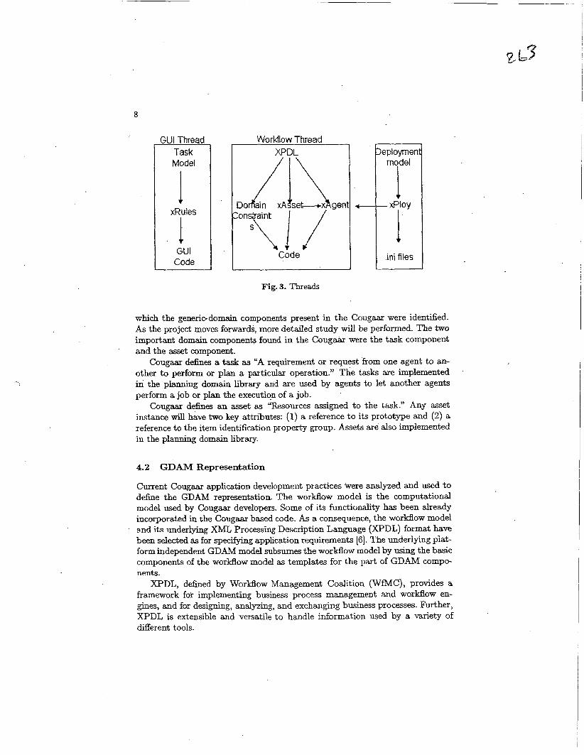
Figure 3 shows the different threads that exist in the developed tool. The threads are designed to capture information pertaining to (1) workflow, (2) GUI layout, and (3) deployment. While the structure and semantics of the workflow thread are known, the details about the GUI and deployment threads are being worked out. The GDAM model representation consists of the Task model for GUI, Workflow model for Agent code and deployment model for deployment code. The models are transformed into corresponding XML representations by the GDAM engine. The GCAM engine reads in the XML, aggregates and corre- lates the information to produce the code artifacts. Higher priority is assigned to developing and refining the workflow thread.
4.1 Domain Components presented i n Cougaar
The Cougaar system provides mechanisms to encode domain knowledge directly in the code. The domain that Cougaar implement is the planning domain for
8
GUI Thread
Model
GUI Code
Workflow Thread XPDL eploymen
model I @lay L I
.ini files
Fig. 3. Threads
which the generic-domain components present in the Cougaar were identified. As the project moves forwards, more detailed study will be performed. The two important domain components found in the Cougaar were the task component and the asset component.
Cougaar defines a task as “A requirement or request from one agent to an- other to perform or plan a particular operation.” The tasks are implemented in the p m a domain library and are used by agents to let another agents perform a job or plan the execution of a job.
Cougaar defines an asset as L‘Fksources assigned to the task.” Any asset instance will have two key attributes: (1) a reference to its prototype and (2) a reference to the item identification property group. Assets are also implemented in the planning domain library.
4.2 GDAM Representation
Current Cougar application development practices were analyzed and used to define the GDAM representation. The workaow model is the computational model used by Cougaar developers. Some of its functionality has been already incorporated in the Cougaar based code. As a consequence, the workflow model and i t s underlying XML Processiq Description Language (XPDL) format have been selected as for speclfylng application requirements 161. The underlying piat- form independent GDAM model subsumes the workflow model by using the basic components of the workflow model as templates for the part of GDAM compo- nents.
XPDL, defined by Workflow Management Coalition (WfMC), provides a framework for implementing business process management and workflow en- ,@es, and for desighg, analyzing, and exchan,&g business processes. Further, XPDL is extensible and versatile to handle information used by a variety of different tools.
9 .
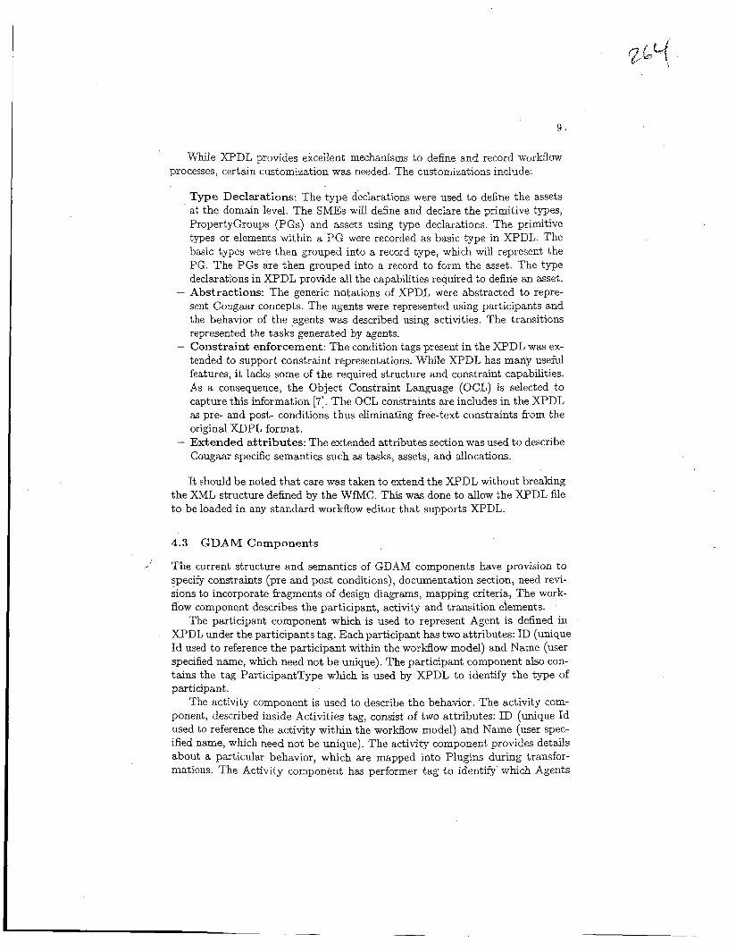
While XPDL provides excellent mechanisms to define and record workflow processes, certain customization was needed. The customizations include:
- Type Declarations: The type declarations were used to define the assets at the domain level. The SMEs will define and declare the primitive types, PropertyGroups (PGs) and assets using type declarations. The primitive types or elements within a PG were recorded as basic type in XPDL. The basic types were then grouped into a record type, which will represent the PG. The PGs are then grouped into a record to form the asset. The type declarations in XPDL provide all the capabilities required to define an asset.
- Abstractions: The generic notations of XPDL were abstracted to repre- sent Cougaar concepts. The agents were represented using participants and the behavior of the agents was described using activities. The transitions represented the tasks generated by agents.
- Constraint enforcement: The condition tags present in the XPDL was ex- tended to support constraint representations. While XPDL has marly useful features, it lacks some of the required structure and constraint capabilities. As a consequence, the Object Constraint Language (OCL) is selected to capture this information [7]. The OCL constraints are includes in the XPDL as pre- and post- conditions thus eliminating free-text constraints from the original XDPL format.
- Extended attr ibutes: The extended attributes section was used to describe Cougaar specific semantics such as tasks, assets, and allocations.
It should be noted that care was taken to extend the XPDL without breaking the XML structure defined by the WfMC. This was done to allow the XPDL file to be loaded in any standard workflow editor that supports XPDL.
4.3 G D A M Components
The current structure and semantics of GDAM components have provision to specify constraints (pre and post conditions), documentation section, need revi- sions to incorporate fragments of design diagams, mapping criteria, The work- flow component describes the participant, activity and transition elements.
The participant component which is used to represent Agent is defined in XPDL under the participants tag. Each participant has two attributes: ID (unique Id used to reference the participant within the workfiow model) and Name (user specified name, which need not be unique). The participant component also con- tains the tag ParticipantType which is used by XPDL to identify the type of participant.
The activity component is used to describe the behavior. The activity com- ponent, described inside Activities tag, consist of two attributes: ID (unique Id used to reference the activity within the workflow model) and Name (user spec- ified name, which need not be unique). The activity component provides details about a particular behavior, which are mapped into Plugins during transfor- mations. The Activity component has performer tag to identify which Agents
10
behavior is being defined, transition restrictions tag to reference the constraints of a particular Task, and an extended attribute namely asset to identify the asset used by the activity. An activity component can occur more than once in the workflow model. The first occurrence of activity component is mapped into a new Ply* and subsequent occurrences result in appending the Plu,@ behavior. The P1u-b behavior is appended by appending the subscription and action subsets of the Plu,@n.
The asset component is used to describe the resources attached to tasks. The asset component is described using XPDLs type declarations. The primitive types or elements within a PG were recorded as basic type in XPDL. The basic types were then grouped into a record ty-pe, which will represent the PG. The PGs are then grouped into a record to form the asset. The TypeDeclaration tag, consist of two attributes: ID (unique Id used to reference the type within the workflow model) and Name (user specified name, which need not be unique). The TypeDeclaration also lists whether the type is basic type or record type. If the type is a record, the members of the record are listed.
5 CMDA Implementation
The graphical user interface (GUI) for the developed CMDA tool has been im- plemented as an editor using the Eclipse DE [8,9]. The editor allows editing and validation of XPDL data in both text and graphical formats. The XPDL is loaded into the editor, with the workflow dqdayed. The editor connects to the repository of components. The user drags components from a palette (represent- ing what’s available in the repository) assigning the activity to a new instance of the component, which can have all its properties set in a GUI. The editor shows any validation errors detected by the validating compiler. The instanti- ation data (component name and property values) are stored in the XPDL as extended attributes. The editor also shows a set of available resources, which can be assigned to each activity. As these resources are assigned, they are stored in the XPDL as extended attributes. Completed requirements include a fuUy defined components with parameters, roles, and deployment data.
Since the entire system is a component itself, with deployment information added, the editor is used to edit any inner component as well. The components are defined in a UMGlike =based language [lo] where an X M L schema is defined for specifying components that can be automatically converted to an EMF [ll] model. Eclipse’s EMF is a modeling system siruiiar to the ivieia-OLj& Facility (MOF) [ll]. Those similarities enable the use EMF and the related tools for easy conversion to a UML representation. The UML representation, in addition to documentation generation, provides a better understanding of the application under development.
The characteristics of the metamodel axe determined from the parameteri- zation of Cougaaz components, related constraints and properties. Components must deiine properties that can be queried and derived. Interconnected compe nents work together as agents and societies of agents. Composition of components

is specified using graphs describing interconnected and configured components. The graphs can be saved and reused.
Generation of Cougaarj Java code, documentation, requirements, and test cases. depends on components that must provide information for artifact gener- ation Deployment of components requires assignment of hosts and other compu- tational, storage, or other type of resources while maintaining Java compatibility.
Each component maps to a UML structured component with template para- meters (Figure 4). The compiler validates components and generates artifacts. The validation insures that the component is valid and is suitable for artifact generation. Artifact generation creates Java code, documentation, test cases, and requirements data.
I I role from Member 2 /, Member 1 >- role from Member 3
1 I \ I
,
I I , / Member 3 , Member 2
Fig. 4. Component
Components have named parameters that are defined like a very small subset of an XML schema [12]. Parameters specify a name attribute, which is matched when given a value. Parameters may also define a parent parameter, thus allow- ing sets of parameters and a cardinality. This allows variable numbers of sets of parameters, giving a reasonable configuration language for components.
The metamodel directly provides constraint data through constraints given in the component definition, and implicitly through the typed connections and defined restrictions on the various metamodel elements. The compiler verifies constraints to assure that a valid system can be generated.
The compiler considers the entire system as one top level component. The components are grouped into a tree of instantiations (component names coupled with values for all of their parameters) that is traversed by the compiler. The compiler calls the relevant profile mapping at each node to generate correspond- ing artifacts. The profile mappings use either an XML tree for the component definition or a set of EMF objects representing them in memory. The former is the serialized form of the latter. Extensible Stylesheet Language (XSL) Trans-
12
formations (XSLT) [13] or Eclipse's Java Emitter Template (JET) [14,15] are then used to generate the artifacts.
Components can specify roles, named interconnections with other compo- nents, that specify data types sent and received over them. Roles are special types of parameters which are fully initialized only with references to other component instances. They also cannot have inner roles or any such hierarchy.
Deployment data is considered a special type of non-hierarchical parameter. Deployment data are not fixed values. They are expression usable for deriving the value when the system is deployed.
Components can spec* inner member components to define the inner struc- ture. These member components are initialized and connected together. Their parameters, connections, and deployment information have static values or OCL expressions [7] based on the component's parameter data. OCL expressions pro- vide additional information t o ob ject-oriented models, including constraints, queries, referencing values, stating conditions and business rules. Each value is expressed using OCL constants or using OCL expressions that allow their derivation. The component can dehe its properties as the values of properties in its member components, possibly with some modification and renaming.
While the definitions immediately provide useful descriptions of the system, they do not directly provide code, test cases, etc. The compiler, in some cases, needs "help" from the component dehitions to create code, test cases, and re- lated artifacts. Each component specifies the name of a Profile Mapping that links the component to a set of definitions for how the artifacts are gener- ated. Each profile mapping handles different categories of components, such as Cougaar Plugins, Agents, or Societies.
6 Conclusions
Cougaar is complex requiring considerable mappings and transforms. MDA pro- vides a systematic way of capturing requirements and mapping them from PIM to PSM and ultimately to the code level. The developed CMDA framework is an MDA based approach for the Cougaar agent-based architecture. It enables au- tomatx transformation of the appiication requirements, expressed in the &"CL format, into a platform-independent, GDAM representation. The artifacts are generated from models assembled using components that contain information re- lated to requirement, design, code, test and documentation details for that com- ponent, dong with transformation information. Platform-specific GCAX com- ponents are derived kom the metamodel and then converted into Cougaar/Java code. The CMDA combines assembly approach with transformations to generate the artifacts. While the CMDA-based approach uses the Cougaar architecture, it is applicable to other agent-based architectures.
'

13
7 Acknowledgements
This work has been supported, in part, by the DARPA STTR grant “AMIIE Phase II - Cougaar Model Driven Architecture Project,” (Cougaar Software, Inc.) subcontract number CSI-2003-01. We would like to acknowledge the efforts, ideas, and support that we received from our research team including Todd Carrico, Sandy Ronston, T im Tschampel, and Boby George.
References
1. -: Cougaar architecture document. Technical report, BBN Technologies (2004)
2. -: Cougaar developers guide. Technical report, BBN Technologies (2004) Version
3. Arlow, J., Neustadt, I.: Enterprise Patterns and MDA: Building Better Software
4. Kleppe, A., Warmer, J., Bast, W.: MDA Explained: The Model Driven Architec-
5. Weis, T., Ulbrich, A., Geihs, K.: Model metamorphosis. IEEE Software 20 (2003)
6. Workflow Management Coalition: (Workflow process definition interface - XML process definition language (XPDL)) http://www.wfmc.org/standards/docs/TC- 1025-10xpd1-102502.pdf.
7. Warmer, J., Kleppe, A.: Object Constraint Language, The: Getting Your Models Ready for MDA. Second edn. Addison Wesley Professional (2004)
8. Clayberg, E., Rubel, D.: Eclipse: Building Commercial-Quality Plug-ins. The Eclipse Series. Addison-Wesley, Boston (2004)
9. Gamma, E., Beck, K.: Contributing to Eclipse: Principles, Patterns, and Plug-Ins. The Eclipse Series. Addison-Welsey, Boston (2004)
10. Rumbaugh, J., Jacobson, I., Booch, G.: The Unified Modeling Language Reference Manual. Addison-Wesley Publishing Co. (2004)
11. Budinsky, F., Steinberg, D., Merks, E., Ellersick, R., Grose, T.J.: Eclipse Modeling Framework. Addison-Wesley Publishing Co. (2003)
12. McLaughlin, B.: JavaTM & XML Data Binding. O’Reilly, Beijing (2002) 13. Tidwell, D.: XSLT. O’Reilly, Beijing (2001) . 14. Azzuri Ltd.: (JET tutorial part 1 (introduction to JET))
15. Azzuri Ltd.: (JET tutorial part 2 (write code that writes code))
Version for Cougaar 11.2.
for Cougaar 11.2.
with Archetype Patterns and UML. Addison-Wesley, Boston (2003)
ture: Practice and Promise. Addison-Wesley, Boston (2003)
46-51
http://eclipse.org/articles/Article-JET/jet_tutoriall. html.
http://eclipse.org/articles/Article- JET/jet-tutorial2.html.