Degradation of Si-Al aluminide coating after service of
10
IOP Conference Series: Materials Science and Engineering OPEN ACCESS Degradation of Si-Al aluminide coating after service of turbine blades made of ZhS6K superalloy To cite this article: B Chmiela et al 2012 IOP Conf. Ser.: Mater. Sci. Eng. 35 012010 View the article online for updates and enhancements. You may also like The resistance of an aluminide coating on a high-strength ASTM A29 steel subjected to a temperature of 850 °C Mohammad Badaruddin, Sugiyanto and Dwi Asmi - High-temperature oxidation and hot corrosion behavior of the Cr-modified aluminide coating obtained by a Thermal Diffusion process Chong Li, Xiaojing Xu, Saifu Wang et al. - High temperature oxidation behavior of low temperature aluminized Mirrax ® ESR steel Tuba Yener, Kadir Mert Doleker and Azmi Erdogan - This content was downloaded from IP address 45.183.92.90 on 17/02/2022 at 18:31
Transcript of Degradation of Si-Al aluminide coating after service of

IOP Conference Series Materials Science and Engineering
OPEN ACCESS
Degradation of Si-Al aluminide coating afterservice of turbine blades made of ZhS6KsuperalloyTo cite this article B Chmiela et al 2012 IOP Conf Ser Mater Sci Eng 35 012010
View the article online for updates and enhancements
You may also likeThe resistance of an aluminide coating ona high-strength ASTM A29 steel subjectedto a temperature of 850 degCMohammad Badaruddin Sugiyanto andDwi Asmi
-
High-temperature oxidation and hotcorrosion behavior of the Cr-modifiedaluminide coating obtained by a ThermalDiffusion processChong Li Xiaojing Xu Saifu Wang et al
-
High temperature oxidation behavior of lowtemperature aluminized Mirraxreg ESR steelTuba Yener Kadir Mert Doleker and AzmiErdogan
-
This content was downloaded from IP address 451839290 on 17022022 at 1831
Degradation of Si-Al aluminide coating after service
of turbine blades made of ZhS6K superalloy
B Chmiela1 M Kianicovaacute
2 M Sozańska
1 and L Swadźba
1
1 Department of Materials Science and Metallurgy Silesian University of Technology
40-019 Katowice Poland 2 Faculty of Special Technology Alexander Dubcek University in Trenčiacuten
Študentskaacute 1 911 50 Trenčiacuten Slovakia
E-mail bartoszchmielapolslpl
Abstract Aero engine turbine blades made of nickel-based superalloys are characterized by
very good mechanical properties but their hot corrosion resistance is insufficient Therefore
various protective coatings must be applied These coatings are typically made of diffusive
aluminide coatings based on theβ-NiAl intermetallic phase Although the oxidation resistance
and hot corrosion resistance of these coatings are very good their thermal resistance is
relatively poor As a result turbine blades with aluminide coatings are prone to degradation in
case of overheating In this paper we study the degradation of the Si-Al aluminide coating on
turbine blades made of ZhS6K superalloy during overheating in the DV2 jet engine
1 Introduction
Aero engines turbine blades are flight safety parts and are produced by the investment casting method
using ceramic molds [12] During service creep thermo-mechanical fatigue and hot corrosion
processes occur [3] Hot corrosion is caused by the mixture of many compounds forming low-melting-
point mixtures (NaCl Na2SO4 SO2 SO3) which leads to failure of the blade surface [4ndash6] Although
the mechanical properties of turbine blades are very high (as a result of proper chemical and phase
composition) the hot corrosion resistance is insufficient Therefore to improve hot corrosion
resistance and oxidation resistance turbine blades are coated with protective coatings [67]
Commonly used are diffusive aluminide coatings based on the β-NiAl intermetallic compound with
a zonal structure Aluminide coatings are characterized by excellent oxidation resistance and hot
corrosion resistance but they suffer from poor thermal resistance Analogous to this TiAl3 coating
deposited onto Ti alloy exhibits a significant influence on a reduction of the oxidative abilities of
Ti-based alloys due to properties of the coating (chemical stability thickness negligible porosity and
strength of substrate-coating chemical bond) [8] Therefore for turbine blades with aluminide
coatings overheating may be very dangerous [7] In this paper we investigate the degradation of
turbine blades made of ZhS6K nickel-base superalloy with a Si-Al aluminide coating after overheating
as a result of compressor stall in the DV2 jet engine [79]
2 Material and experimental procedure
The investigated hollow turbine blades were a precision casting made of ZhS6K nickel-base
superalloy The chemical composition of this alloy is given in table 1
Technologies and Properties of Modern Utilised Materials IOP PublishingIOP Conf Series Materials Science and Engineering 35 (2012) 012010 doi1010881757-899X351012010
Published under licence by IOP Publishing Ltd 1
Table 1 Chemical composition of ZhS6K superalloy (wt )
Ni Cr Co Mo W Al Ti Fe Mn Si C B Zr
balance 105 52 41 47 55 28 18 04 04 015 0035 004
After solidification a solution heat treatment was performed Then the protective aluminide coating
(Si-Al) was deposited on the blade surface (table 2) [7]
Table 2 Heat treatment and chemical-thermal treatment of ZhS6K superalloy
Type of treatment Procedure
homogenization vacuum 1225degC 4 h cooling by argon stream at an
overpressure of 15ndash2 bar
Annealing to remove residual
stress after mechanical treatment
950 ordmC 2 h dwell at temperature in dry argon
cooling in air
Si-Al layer deposition
stage 1 spraying a layer (350 mL coloxyline solution
112 g Al powder 112 g Si powder)
stage 2 diffusion annealing at 1000 ordmC 3 h dwell at
temperature slow cooling in a retort
The DV2 jet engine is characterized by a service life of 1500 h The nominal turbine inlet
temperature is in the range of 800 to 1050 degC but servicing at high temperature is acceptable only for
a short time The maximum acceptable exhaust-gas temperature is 760 degC For the engine investigated
the compressor stall happened (unstable working) after 1676 h of service As a result the high-
pressure turbine overheated for 12 s and the highest exhaust-gas temperature was 977 degC (figure 1)
[7]
Figure 1 Critical temperature excess of DV2 engine
The difference between maximum and acceptable exhaust gas temperature and overheating time
were used to evaluate the blade degradation using the parameter D [11]
dtTtTTTttD
t
t
CC 2
0
3
max02 (1)
where 20 ttt is the overheating duration defined by T TC and Tmax is the maximal overheating
temperature (degC) T(t) is actual engine temperature in the time t (s)
Technologies and Properties of Modern Utilised Materials IOP PublishingIOP Conf Series Materials Science and Engineering 35 (2012) 012010 doi1010881757-899X351012010
2
On the basis of the parameter D it is possible to predict of the degree of blade degradation [7]
(table 3)
Table 3 Degree of blade degradation as a function of D
D (degC 4middots
2) engine status
performance
capability
10middot105 divide 15middot10
9
15middot109 divide 10middot10
10
10middot1010
divide 10middot1012
10middot1012
divide 10middot1014
10middot1014
divide 22middot1014
gt 22middot1014
full performance
degradation of coating of high-pressure turbine blade
degradation of substrate of high-pressure turbine blade
degradation of substrate of low-pressure turbine blade
degradation of basic material of discs
blade melting
service
repair
repair
repair
repair
out of service
After service the DV2 engine was disassembled to investigate the surface and cross-section of the
high-pressure turbine blade The microstructure chemical composition and phase composition were
evaluated using scanning electron microscopy (SEM Hitachi S-4200) a Hitachi S-3400N equipped
with an energy-dispersive spectrometer (EDS Thermo NORAN (System Six)) and electron
backscatter diffraction (EBSD INCA HKL Nordlys II (Channel 5)) The turbine blade was cut
perpendicular to the main axis at 13 of the airfoil length from the tip because in this area the
interaction with hot combustion gases was the strongest [7] Next the specimen was mounted ground
on abrasive paper and polished using diamond and alumina suspensions The cross section was
investigated in the four important areas the leading edge the trailing edge the pressure side and the
suction side (figure 2) For metallographic examination the specimen was etched in a solution of
100 cm3 HCl 100 cm
3 HNO3 100 cm
3 H2O and 3 g MoO3
Figure 2 Cross section of blade (a) and areas investigated on cross section of blade (b)
3 Results and discussion
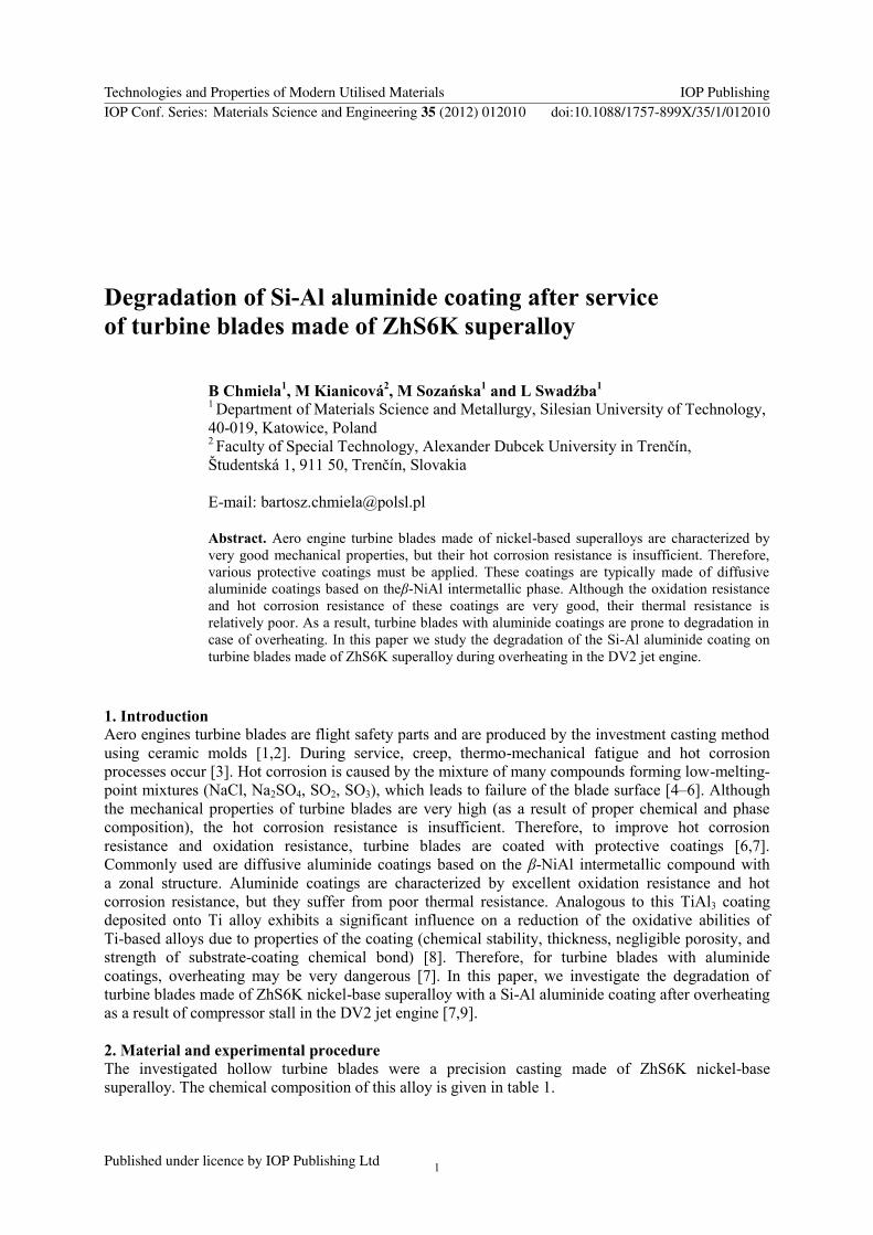
Investigations of the blade surface reveal the appearance of the aluminide coating on the airfoil
Macroscopic observations show that the coating damage is stronger on the suction side (convex side of
the airfoil) than on the pressure side (concave side of the airfoil see figure 3) Visible failures seem
not to be very large but microscopic investigations reveal the real condition The main cause of the
observed damage may be a stronger interaction of hot combustion gases at the suction side
Technologies and Properties of Modern Utilised Materials IOP PublishingIOP Conf Series Materials Science and Engineering 35 (2012) 012010 doi1010881757-899X351012010
3
Figure 3 Surface of
aluminide coating on the
blade airfoil (a) suction side
(b) pressure side
SEM investigation revealed a scale on the airfoil surface cracks and spalling areas (figure 4)
Figure 4 The crack on the blade surface (a) and spalling of the part of blade coating (b)
EDS analysis confirmed the presence of the oxide scale on the suction side and on the pressure side
(figure 5)
Technologies and Properties of Modern Utilised Materials IOP PublishingIOP Conf Series Materials Science and Engineering 35 (2012) 012010 doi1010881757-899X351012010
4
Figure 5 EDS spectra of oxide scale on the airfoil surface (a) suction side (b) pressure side
Qualitative results of EDS analyses clearly suggest the presence of aluminum oxide Moreover the
other elements identified in the scale (sulphur chlorine sodium potassium calcium) indicate an
intensive hot corrosion process and degradation of the coating
On the basis of temperature ( maxT ) and overheating time the parameter D was calculated to be
32middot1011
degC4middots
2 which indicates (Table 1) a high possibility of degradation of the coating and the
substrate (ZhS6K) Investigations into the cross section of the airfoil reveal the real degree of material
degradation (figure 6 and figure 7) Sudden cooling of blade surface from high temperature together
with cooling of substrate by means of internal blade cooling channels lead to the generation of tensile
stresses in the coating (from reason of misfit of coefficient of thermal expansion coating and substrate)
and then cracks perpendicular to the coating - substrate interface
Along with cooling of blade surface condensation of exhaust gases appears and as a result the
corrosion enhances These sites serve as starters for creation and propagation of cracks not only
perpendicular to the interface but also parallel with interface (figure 7) The final consequence of this
mechanism is spalling of the scale (figure 5)
Turbine blades of DV2 engine did not correspond to the state after overheating from the view of
thickness of coating (fig 7) Overheating was caused by incomplete combustion in the chamber ie
impropriate proportion of fuel and air (for example in the consequence of surging) what causes
burning of mixture and high temperature in the low-pressure turbine in the vicinity of thermocouples
This case can be easily revealed by monitoring of parametric engine data as revolutions and
relating fuel flow
Technologies and Properties of Modern Utilised Materials IOP PublishingIOP Conf Series Materials Science and Engineering 35 (2012) 012010 doi1010881757-899X351012010
5
Figure 6 SEM images of the cross section of the blade airfoil (a) leading edge
(b) trailing edge (c) suction side (d) pressure side
The most damaged area was the suction side SEM images reveal hot corrosion pits which expose
the surface of the ZhS6K substrate to the high temperature and combustion gases Moreover some
cracks transpiercing the entire aluminide coating are visible These cracks allow combustion gases to
damage the substrate too On the pressure side of the airfoil only several cracks perpendicular to the
surface were found The leading edge and the trailing edge display slight damage
SEM investigations revealed many needle-shaped precipitates just under the aluminide coating
EDS analysis confirms a high concentration of tungsten molybdenum and chromium (figure 8)
which is characteristic for topologically close packed (TCP) phases Precipitation of TCP phases in
superalloys is typical for long thermal exposure or overheating TCP phases are usually brittle and
decrease the mechanical properties of turbine blades [12]
Technologies and Properties of Modern Utilised Materials IOP PublishingIOP Conf Series Materials Science and Engineering 35 (2012) 012010 doi1010881757-899X351012010
6
Figure 7 SEM images of the cross section
of the blade airfoil (suction side) (a b)
cracks perpendicular to the surface (c)
cracks parallel to the surface
Figure 8 EDS analysis of needle-shaped precipitates under aluminide coating
Because of small size of these precipitates we applied the EBSD technique to identify them [10]
EBSD analysis confirms that needle-shaped precipitates are mainly σ phase (figure 9a)
Technologies and Properties of Modern Utilised Materials IOP PublishingIOP Conf Series Materials Science and Engineering 35 (2012) 012010 doi1010881757-899X351012010
7
Figure 9 Kikuchi patterns of needle-shaped precipitates under the aluminide coating (a) σ phase (b)
probably P phase
Some precipitates are tentatively identified as P phase (figure 9b) This case clearly reveals that EBSD
analysis may be ambiguous The main reasons are (i) the very similar unit cell parameters of σ and P
phases and (ii) the small size of precipitates near the limit of spatial resolution for the EBSD
technique [10]
5 Conclusions
We investigated degraded high-pressure turbine blades and found that blades with diffusive aluminide
coating are very sensitive to overheating caused by unstable working of the engine Although
oxidation resistance of a Si-Al coating is quite good (due to high aluminum content) the thermal
resistance is generally poor Overheating in the short time (12 s) in connection with corrosive
combustion gases caused degradation of the coating by forming pits and cracks Some cracks
transpierce the coating and expose the substrate which may be a reason for ZhS6K superalloy
damage Moreover many precipitates of TCP phases appear just under the coating which confirms
that the temperature was too high in this area All these factors are very dangerous and clearly reveal
that further service of the engine is very risky although its service life is not exceeded
The microstructure of the blade does not correspond to the expected results which should lead to
a high degree of degradation due to the high values of overheating parameters Obviously the
performance capability class (degraded base material of ZhS6K blades and replacement of
high-pressure turbine blades) was incorrectly determined by the manufacturer On the basis of the
criteria determined the structure analyses of blades have confirmed the satisfactory state of blades
This fact led to a repeated examination of the event and all the overheating parameters The
re-examination of local analysis data revealed that the cause of increased critical temperature of outlet
gases was deceleration ie the flame extinction in the combustion chamber which led to a drop in the
revolutions of high-pressure rotor below the nominal value of 53 (idling)
The reaction of the pilot (trying to increase these revolutions) led to shifting the engine control
lever towards higher degrees which increased the flow of fuel into the no-longer burning combustion
chamber Thus a state was reached in the combustion chamber when fuel could not be ignited due to
the low air excess coefficient α
The ignitability of the mixture rich in fuel was renewed where it got mixed with air that cools the
turbine (beyond the first or second stage of low-pressure turbine) depending on what volume of air the
mixture needed to be in the combustion area of the quenching characteristic The combustion outside
the combustion chamber led to a disinformation about the temperature of the operating blades of
high-pressure turbine and it explains the satisfactory microstructure condition of the creep-resistant
coating
Technologies and Properties of Modern Utilised Materials IOP PublishingIOP Conf Series Materials Science and Engineering 35 (2012) 012010 doi1010881757-899X351012010
8
Acknowledgments
Financial support of Structural Funds in the Operational Programme - Innovative Economy (IE OP)
financed from the European Regional Development Fund - Project Modern material technologies in
aerospace industry No POIG010102-00-01508-00 is gratefully acknowledged This work was
also supported by the Ministry of Industry and Trade of the Czech Republic in the frame of the Project
FR-TI1237 099
References
[1] Reed R C 2006 The Superalloys Fundamentals and Applications (Cambridge University Press)
[2] Durand-Charre M 1997 The Microstructure of Superalloys (Amsterdam Overseas Publishers
Association)
[3] Boyce M P 2002 Gas Turbine Engineering Handbook (Houston Gulf Professional Publishing)
[4] Eliaz N Shemesh G and Latanision R M 2002 Eng Fail Anal 9 31
[5] Deb D Iyer S R and Radhakrishnan V M 1996 Mater Lett 29 19
[6] Tamarin Y 2002 Protective Coatings for Turbine Blades (Ohio Materials Park)
[7] Kianicovaacute M 2006 Fireproof diffusive coating degradation in consequence of short-time
operating temperature exceeding PhD Thesis (Trencin Alexander Dubcek University)
[8] Kraacuteľ J Ferdinandy M Kottfer D Maňkovaacute I Ceniga L 2009 Surface Rev and Letters
16 623
[9] Sozańska M Chmiela B Kianicovaacute M and Cwajna J 2012 Solids State Phen 186 143
[10] Chmiela B Sozańska M and Rodak K 2012 Solid State Phen 186 58
[11] Pokluda J and Kianicovaacute M 2010 Gas Turbines Damage and Performance Aassessment of
Protective Coatings on Turbine Blades (India Ed Gurrappa Injeti Sciyo)
Technologies and Properties of Modern Utilised Materials IOP PublishingIOP Conf Series Materials Science and Engineering 35 (2012) 012010 doi1010881757-899X351012010
9
Degradation of Si-Al aluminide coating after service
of turbine blades made of ZhS6K superalloy
B Chmiela1 M Kianicovaacute
2 M Sozańska
1 and L Swadźba
1
1 Department of Materials Science and Metallurgy Silesian University of Technology
40-019 Katowice Poland 2 Faculty of Special Technology Alexander Dubcek University in Trenčiacuten
Študentskaacute 1 911 50 Trenčiacuten Slovakia
E-mail bartoszchmielapolslpl
Abstract Aero engine turbine blades made of nickel-based superalloys are characterized by
very good mechanical properties but their hot corrosion resistance is insufficient Therefore
various protective coatings must be applied These coatings are typically made of diffusive
aluminide coatings based on theβ-NiAl intermetallic phase Although the oxidation resistance
and hot corrosion resistance of these coatings are very good their thermal resistance is
relatively poor As a result turbine blades with aluminide coatings are prone to degradation in
case of overheating In this paper we study the degradation of the Si-Al aluminide coating on
turbine blades made of ZhS6K superalloy during overheating in the DV2 jet engine
1 Introduction
Aero engines turbine blades are flight safety parts and are produced by the investment casting method
using ceramic molds [12] During service creep thermo-mechanical fatigue and hot corrosion
processes occur [3] Hot corrosion is caused by the mixture of many compounds forming low-melting-
point mixtures (NaCl Na2SO4 SO2 SO3) which leads to failure of the blade surface [4ndash6] Although
the mechanical properties of turbine blades are very high (as a result of proper chemical and phase
composition) the hot corrosion resistance is insufficient Therefore to improve hot corrosion
resistance and oxidation resistance turbine blades are coated with protective coatings [67]
Commonly used are diffusive aluminide coatings based on the β-NiAl intermetallic compound with
a zonal structure Aluminide coatings are characterized by excellent oxidation resistance and hot
corrosion resistance but they suffer from poor thermal resistance Analogous to this TiAl3 coating
deposited onto Ti alloy exhibits a significant influence on a reduction of the oxidative abilities of
Ti-based alloys due to properties of the coating (chemical stability thickness negligible porosity and
strength of substrate-coating chemical bond) [8] Therefore for turbine blades with aluminide
coatings overheating may be very dangerous [7] In this paper we investigate the degradation of
turbine blades made of ZhS6K nickel-base superalloy with a Si-Al aluminide coating after overheating
as a result of compressor stall in the DV2 jet engine [79]
2 Material and experimental procedure
The investigated hollow turbine blades were a precision casting made of ZhS6K nickel-base
superalloy The chemical composition of this alloy is given in table 1
Technologies and Properties of Modern Utilised Materials IOP PublishingIOP Conf Series Materials Science and Engineering 35 (2012) 012010 doi1010881757-899X351012010
Published under licence by IOP Publishing Ltd 1
Table 1 Chemical composition of ZhS6K superalloy (wt )
Ni Cr Co Mo W Al Ti Fe Mn Si C B Zr
balance 105 52 41 47 55 28 18 04 04 015 0035 004
After solidification a solution heat treatment was performed Then the protective aluminide coating
(Si-Al) was deposited on the blade surface (table 2) [7]
Table 2 Heat treatment and chemical-thermal treatment of ZhS6K superalloy
Type of treatment Procedure
homogenization vacuum 1225degC 4 h cooling by argon stream at an
overpressure of 15ndash2 bar
Annealing to remove residual
stress after mechanical treatment
950 ordmC 2 h dwell at temperature in dry argon
cooling in air
Si-Al layer deposition
stage 1 spraying a layer (350 mL coloxyline solution
112 g Al powder 112 g Si powder)
stage 2 diffusion annealing at 1000 ordmC 3 h dwell at
temperature slow cooling in a retort
The DV2 jet engine is characterized by a service life of 1500 h The nominal turbine inlet
temperature is in the range of 800 to 1050 degC but servicing at high temperature is acceptable only for
a short time The maximum acceptable exhaust-gas temperature is 760 degC For the engine investigated
the compressor stall happened (unstable working) after 1676 h of service As a result the high-
pressure turbine overheated for 12 s and the highest exhaust-gas temperature was 977 degC (figure 1)
[7]
Figure 1 Critical temperature excess of DV2 engine
The difference between maximum and acceptable exhaust gas temperature and overheating time
were used to evaluate the blade degradation using the parameter D [11]
dtTtTTTttD
t
t
CC 2
0
3
max02 (1)
where 20 ttt is the overheating duration defined by T TC and Tmax is the maximal overheating
temperature (degC) T(t) is actual engine temperature in the time t (s)
Technologies and Properties of Modern Utilised Materials IOP PublishingIOP Conf Series Materials Science and Engineering 35 (2012) 012010 doi1010881757-899X351012010
2
On the basis of the parameter D it is possible to predict of the degree of blade degradation [7]
(table 3)
Table 3 Degree of blade degradation as a function of D
D (degC 4middots
2) engine status
performance
capability
10middot105 divide 15middot10
9
15middot109 divide 10middot10
10
10middot1010
divide 10middot1012
10middot1012
divide 10middot1014
10middot1014
divide 22middot1014
gt 22middot1014
full performance
degradation of coating of high-pressure turbine blade
degradation of substrate of high-pressure turbine blade
degradation of substrate of low-pressure turbine blade
degradation of basic material of discs
blade melting
service
repair
repair
repair
repair
out of service
After service the DV2 engine was disassembled to investigate the surface and cross-section of the
high-pressure turbine blade The microstructure chemical composition and phase composition were
evaluated using scanning electron microscopy (SEM Hitachi S-4200) a Hitachi S-3400N equipped
with an energy-dispersive spectrometer (EDS Thermo NORAN (System Six)) and electron
backscatter diffraction (EBSD INCA HKL Nordlys II (Channel 5)) The turbine blade was cut
perpendicular to the main axis at 13 of the airfoil length from the tip because in this area the
interaction with hot combustion gases was the strongest [7] Next the specimen was mounted ground
on abrasive paper and polished using diamond and alumina suspensions The cross section was
investigated in the four important areas the leading edge the trailing edge the pressure side and the
suction side (figure 2) For metallographic examination the specimen was etched in a solution of
100 cm3 HCl 100 cm
3 HNO3 100 cm
3 H2O and 3 g MoO3
Figure 2 Cross section of blade (a) and areas investigated on cross section of blade (b)
3 Results and discussion
Investigations of the blade surface reveal the appearance of the aluminide coating on the airfoil
Macroscopic observations show that the coating damage is stronger on the suction side (convex side of
the airfoil) than on the pressure side (concave side of the airfoil see figure 3) Visible failures seem
not to be very large but microscopic investigations reveal the real condition The main cause of the
observed damage may be a stronger interaction of hot combustion gases at the suction side
Technologies and Properties of Modern Utilised Materials IOP PublishingIOP Conf Series Materials Science and Engineering 35 (2012) 012010 doi1010881757-899X351012010
3
Figure 3 Surface of
aluminide coating on the
blade airfoil (a) suction side
(b) pressure side
SEM investigation revealed a scale on the airfoil surface cracks and spalling areas (figure 4)
Figure 4 The crack on the blade surface (a) and spalling of the part of blade coating (b)
EDS analysis confirmed the presence of the oxide scale on the suction side and on the pressure side
(figure 5)
Technologies and Properties of Modern Utilised Materials IOP PublishingIOP Conf Series Materials Science and Engineering 35 (2012) 012010 doi1010881757-899X351012010
4
Figure 5 EDS spectra of oxide scale on the airfoil surface (a) suction side (b) pressure side
Qualitative results of EDS analyses clearly suggest the presence of aluminum oxide Moreover the
other elements identified in the scale (sulphur chlorine sodium potassium calcium) indicate an
intensive hot corrosion process and degradation of the coating
On the basis of temperature ( maxT ) and overheating time the parameter D was calculated to be
32middot1011
degC4middots
2 which indicates (Table 1) a high possibility of degradation of the coating and the
substrate (ZhS6K) Investigations into the cross section of the airfoil reveal the real degree of material
degradation (figure 6 and figure 7) Sudden cooling of blade surface from high temperature together
with cooling of substrate by means of internal blade cooling channels lead to the generation of tensile
stresses in the coating (from reason of misfit of coefficient of thermal expansion coating and substrate)
and then cracks perpendicular to the coating - substrate interface
Along with cooling of blade surface condensation of exhaust gases appears and as a result the
corrosion enhances These sites serve as starters for creation and propagation of cracks not only
perpendicular to the interface but also parallel with interface (figure 7) The final consequence of this
mechanism is spalling of the scale (figure 5)
Turbine blades of DV2 engine did not correspond to the state after overheating from the view of
thickness of coating (fig 7) Overheating was caused by incomplete combustion in the chamber ie
impropriate proportion of fuel and air (for example in the consequence of surging) what causes
burning of mixture and high temperature in the low-pressure turbine in the vicinity of thermocouples
This case can be easily revealed by monitoring of parametric engine data as revolutions and
relating fuel flow
Technologies and Properties of Modern Utilised Materials IOP PublishingIOP Conf Series Materials Science and Engineering 35 (2012) 012010 doi1010881757-899X351012010
5
Figure 6 SEM images of the cross section of the blade airfoil (a) leading edge
(b) trailing edge (c) suction side (d) pressure side
The most damaged area was the suction side SEM images reveal hot corrosion pits which expose
the surface of the ZhS6K substrate to the high temperature and combustion gases Moreover some
cracks transpiercing the entire aluminide coating are visible These cracks allow combustion gases to
damage the substrate too On the pressure side of the airfoil only several cracks perpendicular to the
surface were found The leading edge and the trailing edge display slight damage
SEM investigations revealed many needle-shaped precipitates just under the aluminide coating
EDS analysis confirms a high concentration of tungsten molybdenum and chromium (figure 8)
which is characteristic for topologically close packed (TCP) phases Precipitation of TCP phases in
superalloys is typical for long thermal exposure or overheating TCP phases are usually brittle and
decrease the mechanical properties of turbine blades [12]
Technologies and Properties of Modern Utilised Materials IOP PublishingIOP Conf Series Materials Science and Engineering 35 (2012) 012010 doi1010881757-899X351012010
6
Figure 7 SEM images of the cross section
of the blade airfoil (suction side) (a b)
cracks perpendicular to the surface (c)
cracks parallel to the surface
Figure 8 EDS analysis of needle-shaped precipitates under aluminide coating
Because of small size of these precipitates we applied the EBSD technique to identify them [10]
EBSD analysis confirms that needle-shaped precipitates are mainly σ phase (figure 9a)
Technologies and Properties of Modern Utilised Materials IOP PublishingIOP Conf Series Materials Science and Engineering 35 (2012) 012010 doi1010881757-899X351012010
7
Figure 9 Kikuchi patterns of needle-shaped precipitates under the aluminide coating (a) σ phase (b)
probably P phase
Some precipitates are tentatively identified as P phase (figure 9b) This case clearly reveals that EBSD
analysis may be ambiguous The main reasons are (i) the very similar unit cell parameters of σ and P
phases and (ii) the small size of precipitates near the limit of spatial resolution for the EBSD
technique [10]
5 Conclusions
We investigated degraded high-pressure turbine blades and found that blades with diffusive aluminide
coating are very sensitive to overheating caused by unstable working of the engine Although
oxidation resistance of a Si-Al coating is quite good (due to high aluminum content) the thermal
resistance is generally poor Overheating in the short time (12 s) in connection with corrosive
combustion gases caused degradation of the coating by forming pits and cracks Some cracks
transpierce the coating and expose the substrate which may be a reason for ZhS6K superalloy
damage Moreover many precipitates of TCP phases appear just under the coating which confirms
that the temperature was too high in this area All these factors are very dangerous and clearly reveal
that further service of the engine is very risky although its service life is not exceeded
The microstructure of the blade does not correspond to the expected results which should lead to
a high degree of degradation due to the high values of overheating parameters Obviously the
performance capability class (degraded base material of ZhS6K blades and replacement of
high-pressure turbine blades) was incorrectly determined by the manufacturer On the basis of the
criteria determined the structure analyses of blades have confirmed the satisfactory state of blades
This fact led to a repeated examination of the event and all the overheating parameters The
re-examination of local analysis data revealed that the cause of increased critical temperature of outlet
gases was deceleration ie the flame extinction in the combustion chamber which led to a drop in the
revolutions of high-pressure rotor below the nominal value of 53 (idling)
The reaction of the pilot (trying to increase these revolutions) led to shifting the engine control
lever towards higher degrees which increased the flow of fuel into the no-longer burning combustion
chamber Thus a state was reached in the combustion chamber when fuel could not be ignited due to
the low air excess coefficient α
The ignitability of the mixture rich in fuel was renewed where it got mixed with air that cools the
turbine (beyond the first or second stage of low-pressure turbine) depending on what volume of air the
mixture needed to be in the combustion area of the quenching characteristic The combustion outside
the combustion chamber led to a disinformation about the temperature of the operating blades of
high-pressure turbine and it explains the satisfactory microstructure condition of the creep-resistant
coating
Technologies and Properties of Modern Utilised Materials IOP PublishingIOP Conf Series Materials Science and Engineering 35 (2012) 012010 doi1010881757-899X351012010
8
Acknowledgments
Financial support of Structural Funds in the Operational Programme - Innovative Economy (IE OP)
financed from the European Regional Development Fund - Project Modern material technologies in
aerospace industry No POIG010102-00-01508-00 is gratefully acknowledged This work was
also supported by the Ministry of Industry and Trade of the Czech Republic in the frame of the Project
FR-TI1237 099
References
[1] Reed R C 2006 The Superalloys Fundamentals and Applications (Cambridge University Press)
[2] Durand-Charre M 1997 The Microstructure of Superalloys (Amsterdam Overseas Publishers
Association)
[3] Boyce M P 2002 Gas Turbine Engineering Handbook (Houston Gulf Professional Publishing)
[4] Eliaz N Shemesh G and Latanision R M 2002 Eng Fail Anal 9 31
[5] Deb D Iyer S R and Radhakrishnan V M 1996 Mater Lett 29 19
[6] Tamarin Y 2002 Protective Coatings for Turbine Blades (Ohio Materials Park)
[7] Kianicovaacute M 2006 Fireproof diffusive coating degradation in consequence of short-time
operating temperature exceeding PhD Thesis (Trencin Alexander Dubcek University)
[8] Kraacuteľ J Ferdinandy M Kottfer D Maňkovaacute I Ceniga L 2009 Surface Rev and Letters
16 623
[9] Sozańska M Chmiela B Kianicovaacute M and Cwajna J 2012 Solids State Phen 186 143
[10] Chmiela B Sozańska M and Rodak K 2012 Solid State Phen 186 58
[11] Pokluda J and Kianicovaacute M 2010 Gas Turbines Damage and Performance Aassessment of
Protective Coatings on Turbine Blades (India Ed Gurrappa Injeti Sciyo)
Technologies and Properties of Modern Utilised Materials IOP PublishingIOP Conf Series Materials Science and Engineering 35 (2012) 012010 doi1010881757-899X351012010
9
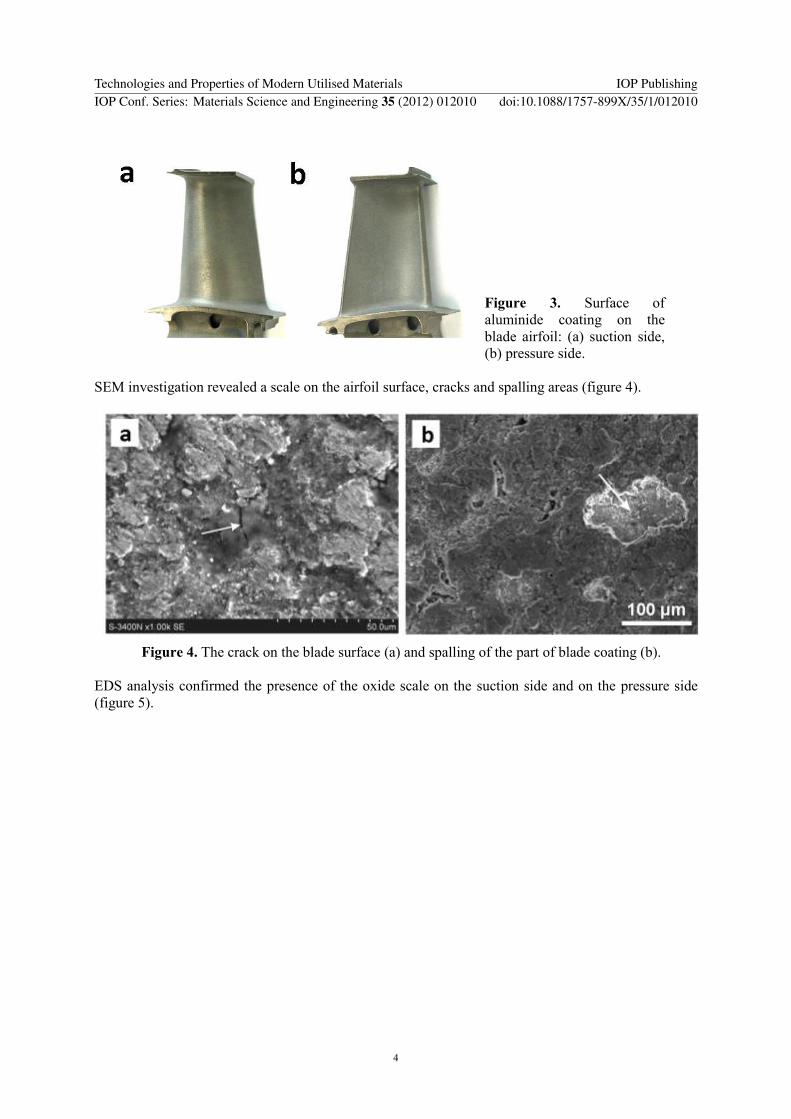