


Degenerate Quantum Gases manipulation on AtomChips Francesco Saverio Cataliotti.
34
Degenerate Quantum Gases manipulation on AtomChips Francesco Saverio Cataliotti
-
Upload
egbert-wood -
Category
Documents
-
view
224 -
download
4
Transcript of Degenerate Quantum Gases manipulation on AtomChips Francesco Saverio Cataliotti.

Degenerate Quantum Gases manipulation on AtomChips
Francesco Saverio Cataliotti

• Bose-Einstein condensates on a microchip
• Atom Interferometry
• Multipath Interferometry on an AtomChip
• Results and Conclusions
Outlook

Degenerate Atoms1925: Einstein predicts “condensation” of bosons
80’s: Development of laser cooling
1985: Magnetic Trapping of ultracold atoms
1986: Optical trapping of Na
1987: Na Magneto-Optical Trap
60’s: Development of Lasers
1995: First 87Rb Bose-Einstein Condensate
2001: First BEC of 87Rb on an Atom Chip
Huge playground for fundamental physics:- BEC with Li, Na, K, Cs, Fr…- Optical gratings, collective excitations…
First applications:- Interferometry- Earth and Space sensors- Quantum Information

612.23 dBn
T 300 K 10-20
Route to BEC in dilute gases
laser cooling
evaporative cooling
10-6T 10 K
T 100 nK 2.6

tem
pera
ture
Evaporative cooling
E
x
Forced evaporation in a magnetic trap (conservative
potential)
remove highest velocities
thermalization through elastic
collisions
cooling

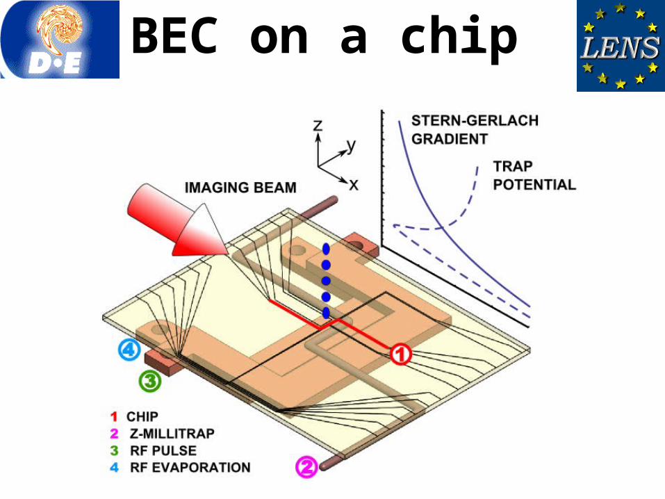
BEC on a chipMacroscopic trap Micro-trap
I
Current ~ 100 APower ~ 1.5 kW
double MOT system: Laser power ~ 500 mW
Ultra High Vacuum ~ 10-11 Torr
n = 10-100 Hz Current < 1 APower < 10 W
single MOT system: Laser power ~ 100 mW
High Vacuum ~ 10-9 Torr
Large BEC 106 atomsbutproduction cycle > 1 min
BEC 105 atomsandproduction cycle ~ 1 s
n = 1-100 kHz

• Planar Geometry gold microstrips on silicon substrates
Bwir (Iwir= 3A) Bbias = {0,3.3,1.2} Gauss
1000 2000 3000 4000 5000
12345678
2000 1000 1000 2000
12345678
z (mm)
x (mm)
1000 2000 3000 4000 5000
12345678
2000 1000 1000 2000
12345678
|B| (
Gau
ss)
|B| (
Gau
ss)
Iwir= 3 A ; Bbias= {0,3.3,1.2} Gauss Iwir= 1 A ; Bbias= {0,3.3,1.2} Gauss
BEC on a chip

BEC Generation RoutineMOT in reflection loading10^8 atoms
MOT transfer close to the chip (~1mm)
CMOT + Molasses 5 x 10^7 atoms @ T ~ 10 μK
Optical pumpingAncillary magnetic trap (big Z wire)20 x 10^6 atoms @ T ~ 12 μK
Compression and transfer to themagnetic trap on chip (chip Z wire)20 x 10^6 atoms @ T ~ 50 μK (~200 μm)
Evaporation (big U under the chip)BEC with 30x10^3 atoms, Tc=0.5 μK
End of the cycle
5000
5450
5485
5490
5740
8300
time [ms] action
23000

MOT ~ 10^8 atoms
Molasses phase ~ 5 x 10^7 atoms @ T ~ 15 uK
First Magnetic Trap (big Z wire)~ 20 x 10^6 atoms @ T ~ 12 uK
Magnetic Trap on Chip (chip Z wire)~ 20 x 10^6 atoms @ T ~ 50 uK
BEC~ 20 x 10^3 atoms @ T < 0.5 uK
Free fall of the BEC
BEC on a chip

• Bose-Einstein condensates on a microchip
• Atom Interferometry
• Multipath Interferometry on an AtomChip
• Results and Conclusions
Outlook

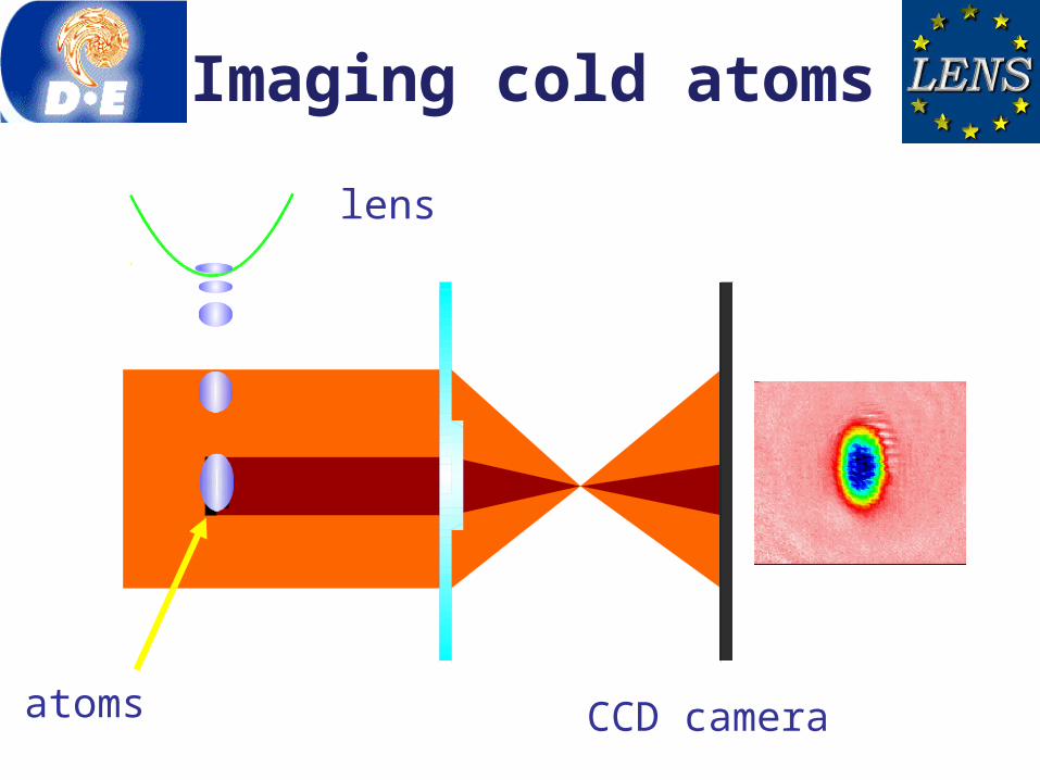
Atom Interferometer
coupling mechanism
BEC 1 BEC 1
BEC 2BEC 1,2
BEC 1
BEC 2
separation for measurement
Rabi pulse
Stern-Gerlach experiment
BEC – coherent form of matter , a wavepacket
BEC 1,2 different spin states

Atomic Ramsey Interferometer
- Theory -
Solve SE for 1 atomfor the non-interacting BEC
1
2Δ=ω 0 -ω
ω ω0let them evolvefor time T
mix them up again
start from
mix two states
Solve GPE for the BEC

Rabi Oscillations
mf=1mf=2mf=2
time
Tp
BECmf=1
BECmf=2
B
Δ
spac
e
Stern-Gerlach method
- pulse
Rabi frequency

Experimental Scheme:Ramsey Interferometer
mf=2mf=2 mf=1
mf=1
mf=2B
Δ
time
spac
e
π/2 π/2

• Bose-Einstein condensates on a microchip
• Atom Interferometry
• Multipath Interferometry on an AtomChip
• Results and Conclusions
Outlook

Parameters of the Interferometric Signal
background
Sensitivity:
Resolution:
D’Ariano & Paris, PRA (1996)amplitude
24
Working range:
Weihs et al., Opt. Lett. (1996)

Multi-Path interferometer
0000
000
000
000
0000W W W W
Funny enougn for N>3 the system can be aperiodic since frequencies are incommensurableEven more fun they are the solutions of a complex Fibonacci Polynomial
)()()( 11 xFxxFxF nnn

Multi-Path interferometer
There does not exist a p/2 pulse.To obtain the best resolution from the interferometer one has to optimize pulse area

• Bose-Einstein condensates on a microchip
• Atom Interferometry
• Multipath Interferometry on an AtomChip
• Results and Conclusions
Outlook

Detection of a Light-Induced Phase Shift
Polarisation σ- Polarisation σ+
Light-pulse detuning from F=2 F=3 was 6.8GHz.
32
What can you use it for?

• We have demonstrated a compact time-domain multi-path interferometer on an atom chip
• Sensitivity can be controlled by an RF pulse acting as a controllable state splitter.
• Resolution superior to that of an ideal two-path interferometer.
• Simultaneous measurement of multiple signals at the output enables a range of advanced sensing applications in atomic physics and optics
• Integration of interferometer with a chip puts it into consideration for future portable cold-atom based measurement systems.
Conclusions

Atom Chip Team
Ivan Herrera
Pietro Lombardi
our typical signal
Jovana Petrovic
Those who really did it

Ivan Herrera
Pietro Lombardi
A typical BEC
Jovana Petrovic
Who did it?


![SECTORIAL FORMS AND DEGENERATE DIFFERENTIAL OPERATORS€¦ · SECTORIAL FORMS AND DEGENERATE DIFFERENTIAL OPERATORS 35 [25]. By our approach we may allow degenerate coefficients](https://static.fdocuments.in/doc/165x107/5e921c5c4d7aaf24746c11ab/sectorial-forms-and-degenerate-differential-operators-sectorial-forms-and-degenerate.jpg)