Deformation Properties of Single Red Blood Cell in a ... · Deformation Properties of Single Red...
8
APCOM & ISCM 11-14 th December, 2013, Singapore 1 Deformation Properties of Single Red Blood Cell in a Stenosed Microchannel P.G.H. Nayanajith¹, S. C. Saha¹, and Y.T. Gu¹* 1 School of Chemistry, Physics and Mechanical Engineering Queensland University of Technology, Brisbane, Queensland, Australia *Corresponding author: [email protected] Abstract Red Blood Cells (RBCs) exhibit different types of motions and different deformed shapes, when they move through capillaries. RBCs can travel through capillaries having smaller diameters than RBCs’ diameter, due to the capacity of high deformability of the viscoelastic RBC membrane. The motion and the steady state shape of the RBCs depend on many factors, such as the geometrical parameters of the microvessel through which blood flows, the RBC membrane bending stiffness and the flow velocity. In this study, the effect of the RBC’s membrane stiffness on the deformation of a single RBC in a stenosed capillary is comprehensively examined. Smoothed Particle Hydrodynamics (SPH) in combination with the two-dimensional spring network membrane model is used to investigate the motion and the deformation property of the RBC. The simulation results demonstrate that the membrane bending stiffness of the RBC has a significant impact on the RBCs’ deformability. Keywords: Red Blood Cell (RBC), Smoothed Particle Hydrodynamics (SPH), Stenosed Capillary, Meshfree Methods, Microcirculation, Numerical Simulations. Introduction RBCs are the most common type of the blood cell in the human blood and they occupy about 45% of total blood volume (Skalak et al. 1989, Tsubota et al. 2006a). Human RBCs consist of a thin viscoelastic membrane and they do not contain nuclei inside of the cell. Due to the existence of the viscoelastic membrane, RBCs exhibit different types of motions and deformed shapes, when the blood flows within the cardiovascular network (Fedosov et al. 2010, Pozrikidis 2003). The motion and the deformation mechanism of a RBC highly depend on the maximum velocity of the plasma flow, bending stiffness of the RBC and the diameter of the microchannel, through which the RBC flows (Shi et al. 2012). Over the last few decades, a number of numerical studies were conducted to understand the RBCs’ behaviour in the microchannels. It is important to study the RBCs’ motion and deformation accurately, when they are squeezing through capillaries. Since, some diseases such as malaria, cancer, and sickle cell anemia can alter
Transcript of Deformation Properties of Single Red Blood Cell in a ... · Deformation Properties of Single Red...

APCOM & ISCM
11-14th
December, 2013, Singapore
1
Deformation Properties of Single Red Blood Cell in a Stenosed Microchannel
P.G.H. Nayanajith¹, S. C. Saha¹, and Y.T. Gu¹* 1School of Chemistry, Physics and Mechanical Engineering
Queensland University of Technology, Brisbane, Queensland, Australia
*Corresponding author: [email protected]
Abstract
Red Blood Cells (RBCs) exhibit different types of motions and different deformed shapes, when
they move through capillaries. RBCs can travel through capillaries having smaller diameters than
RBCs’ diameter, due to the capacity of high deformability of the viscoelastic RBC membrane. The
motion and the steady state shape of the RBCs depend on many factors, such as the geometrical
parameters of the microvessel through which blood flows, the RBC membrane bending stiffness
and the flow velocity. In this study, the effect of the RBC’s membrane stiffness on the deformation
of a single RBC in a stenosed capillary is comprehensively examined. Smoothed Particle
Hydrodynamics (SPH) in combination with the two-dimensional spring network membrane model
is used to investigate the motion and the deformation property of the RBC. The simulation results
demonstrate that the membrane bending stiffness of the RBC has a significant impact on the RBCs’
deformability.
Keywords: Red Blood Cell (RBC), Smoothed Particle Hydrodynamics (SPH), Stenosed Capillary,
Meshfree Methods, Microcirculation, Numerical Simulations.
Introduction
RBCs are the most common type of the blood cell in the human blood and they occupy about 45%
of total blood volume (Skalak et al. 1989, Tsubota et al. 2006a). Human RBCs consist of a thin
viscoelastic membrane and they do not contain nuclei inside of the cell. Due to the existence of the
viscoelastic membrane, RBCs exhibit different types of motions and deformed shapes, when the
blood flows within the cardiovascular network (Fedosov et al. 2010, Pozrikidis 2003). The motion
and the deformation mechanism of a RBC highly depend on the maximum velocity of the plasma
flow, bending stiffness of the RBC and the diameter of the microchannel, through which the RBC
flows (Shi et al. 2012). Over the last few decades, a number of numerical studies were conducted to
understand the RBCs’ behaviour in the microchannels.
It is important to study the RBCs’ motion and deformation accurately, when they are squeezing
through capillaries. Since, some diseases such as malaria, cancer, and sickle cell anemia can alter

APCOM & ISCM
11-14th
December, 2013, Singapore
2
the ability of deformability of the RBCs (Jiang et al. 2013), they might not be able to deform
enough to pass through the narrow capillaries. Further, if the blood vessel is stenosed, there is a
high risk of micro vascular blockage (Cooke et al. 2001). In the past, most of the studies were
carried out to investigate the RBCs’ behaviour in the microchannels with uniform cross sectional
areas and few studies have been done to explore the RBCs’ motion and deformation mechanism in
stenosed microchannels. Hosseini and Feng (2009) have presented the RBCs’ ability of squeezing
through a tiny capillary, whose diameter is smaller than the mean diameter of the RBCs. They used
the SPH method and modelled the microchannel, such that it has a larger uniform diameter at the
inlet and a smaller uniform diameter at the outlet. Vahidkhah and Fatouraee (2012) proposed a
immersed boundary–lattice Boltzmann method to investigate the RBCs’ behaviour in a stenosed
arteriole. However, they presented more qualitative results of the RBCs’ deformation in a stenosed
arteriole.
The purpose of this paper is to present an advanced numerical modelling technique using SPH to
analyse motion and deformation of a single RBC through a stenosed capillary. The RBC membrane
is modelled by a spring network and the forces acting on the RBC membrane is determined based
on the minimum energy principle (Gallage et al. 2012a, Pan and Wang 2009, Tsubota et al. 2006b).
First, we present the motion and deformation of a RBC, when it passes through a stenosed capillary.
Then, we compare the effect of the RBC’s membrane stiffness on the deformation and the motion
of the RBC.
Model and Method
In this study, the RBC membrane is modelled by a two-dimensional spring network as used in the
previous studies (Gallage et al. 2012b, Shi et al. 2012). The membrane of the RBC is constructed by
88 membrane particles, which are interconnected by elastic springs. Initially, it is assumed that the
shape of the RBC membrane is a circle with radius of 2.8 µm.
2
1
0
2
1
N
i o
ill
l
llKE
(1)
N
i
ibb KE
1
2
2tan
2
1
(2)
2
2
1
e
ess
s
ssKE
(3)

APCOM & ISCM
11-14th
December, 2013, Singapore
3
i
sbli
EEE
rF
(4)
Fig. 1: Spring network model of the RBC
The elastic energy (El) stored in the springs due to the stretch/ compression is given by Eq. (1) and
the elastic bending energy (Eb) stored in the springs due to the bending is given by Eq. (2). In order
to maintain a constant membrane area, a penalty function (Es) is introduced as in Eq. (3). The total
force (Fi) acting on the ith
membrane particle is calculated, using the principal of virtual work as in
Eq. (4), where ri is the Position vector of the ith
Particle. li, θi, and s are length of the ith
spring,
angle between two consecutive springs and area of the RBC respectively. Spring constant for
stretching/compression (Kl), spring constant for bending (Kb) and penalty coefficient (Ks) are set to
5×10⁻⁸
N.m, 5×10⁻¹⁰
N.m and 1×10⁻⁵
N.m respectively as used by Shi et al. (2012). The reference
length (l0) is taken as 0.2 µm, while the Equivalent area of the RBC (se) is set to π×(2.8×10⁻⁶
)2×0.55
m2
as used in the work by Pan and Wang (2009).When the forces acting on the RBC membrane
particles are minimised, the initial circular shape gives a biconcave shape as shown in Fig. 1.
RBC internal fluid (cytoplasm) and external fluid (plasma) are modelled by a set of particles and
Navier-Stokes equations (Eq. (5) and Eq. (6)) in Langrangian form are used to model the whole
flow field, with the assumption of the system is isothermal.
ν
Dt
D (5)
fνν
21
p
Dt
D (6)
where ρ and µ are the density and the dynamic viscosity of the fluid, ν is the velocity vector and p is
the pressure while f is the vectorial external force.
In SPH methodology, any field function value (f) of a particle can be approximated from the same
field function value of surrounding neighbouring particles using a kernel function (W) as shown in
li θ
i
mk
mj
mi
APCOM & ISCM
11-14th
December, 2013, Singapore
4
Eq. (7). For this study, popular cubic spline smoothing function is used as used by Gallage et al.
(2012b).
ijj
N
j j
j
i Wfm
f
1
(7)
The Navier-Stokes equations are modified according to the SPH methodology (Liu and Liu 2003)
and are used to determine the particle positions and velocities. The capillary wall is modelled by a
set of boundary particles and pair-wisely repulsive forces are introduced to avoid any penetration of
fluid particles through the capillary wall (Gallage et al. 2012b).
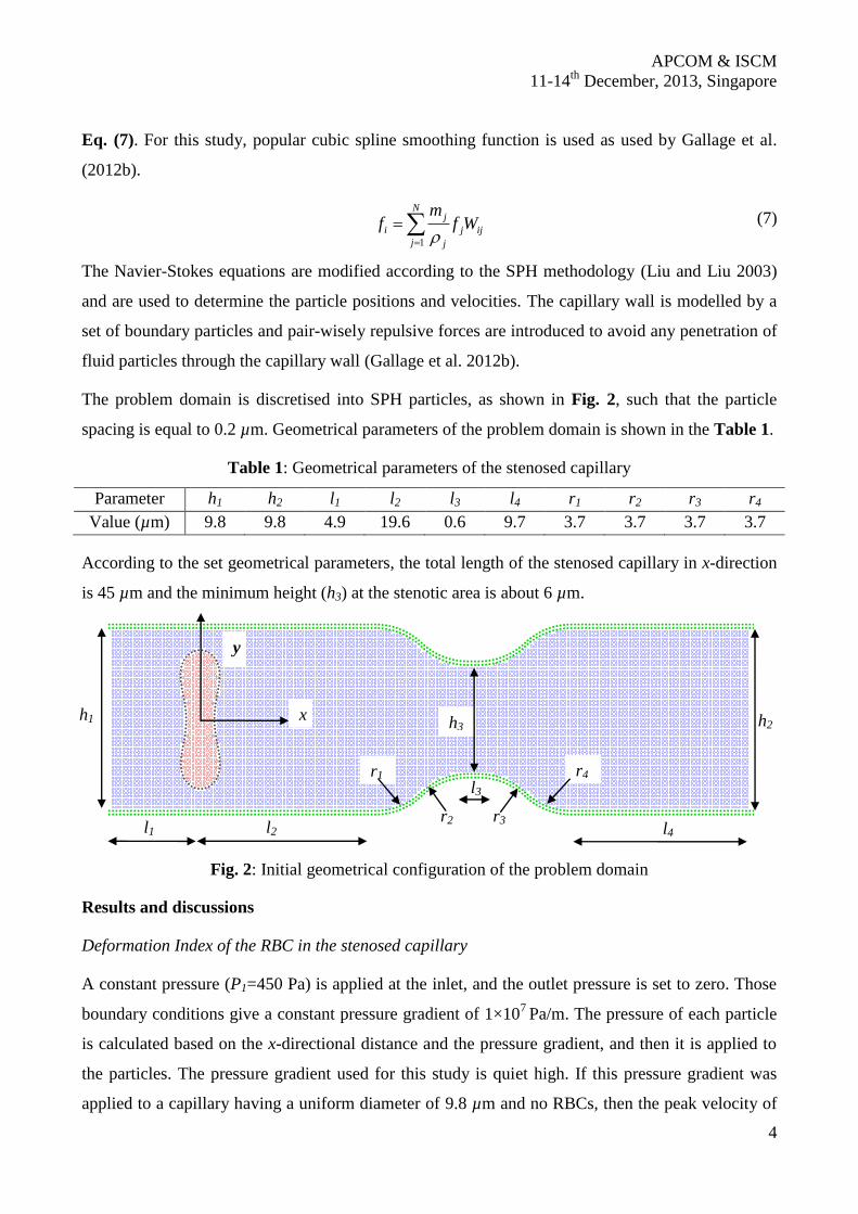
The problem domain is discretised into SPH particles, as shown in Fig. 2, such that the particle
spacing is equal to 0.2 µm. Geometrical parameters of the problem domain is shown in the Table 1.
Table 1: Geometrical parameters of the stenosed capillary
Parameter h1 h2 l1 l2 l3 l4 r1 r2 r3 r4
Value (µm) 9.8 9.8 4.9 19.6 0.6 9.7 3.7 3.7 3.7 3.7
According to the set geometrical parameters, the total length of the stenosed capillary in x-direction
is 45 µm and the minimum height (h3) at the stenotic area is about 6 µm.
Fig. 2: Initial geometrical configuration of the problem domain
Results and discussions
Deformation Index of the RBC in the stenosed capillary
A constant pressure (P1=450 Pa) is applied at the inlet, and the outlet pressure is set to zero. Those
boundary conditions give a constant pressure gradient of 1×10⁷
Pa/m. The pressure of each particle
is calculated based on the x-directional distance and the pressure gradient, and then it is applied to
the particles. The pressure gradient used for this study is quiet high. If this pressure gradient was
applied to a capillary having a uniform diameter of 9.8 µm and no RBCs, then the peak velocity of
V10 5E-06 1E-05 1.5E-05 2E-05 2.5E-05
h1 h2
l1 l2
l3
l4 r2 r3
r4 r1
h3 x
y

APCOM & ISCM
11-14th
December, 2013, Singapore
5
V1
V2
-1E-05 -5E-06 0 5E-06 1E-05
-1E-05
-5E-06
0
5E-06
V1
V2
-5E-06 0 5E-06 1E-05 1.5E-05
-1E-05
-5E-06
0
5E-06
V1
V2
2E-05 2.5E-05 3E-05 3.5E-05 4E-05
-1E-05
-5E-06
0
5E-06
V1
V2
2E-05 2.5E-05 3E-05 3.5E-05 4E-05
-1E-05
-5E-06
0
5E-06
V1
V2
2E-05 2.5E-05 3E-05 3.5E-05
-1E-05
-5E-06
0
5E-06
V12E-05 2.5E-05 3E-05 3.5E-05 4E-05
5
6
0
6
the plasma flow would be 0.12005 m/s. It corresponds to Reynolds number, Re=1.17649. Due to the
applied pressure in the inlet, the RBC begins to move with plasma flow. While RBC is moving it
deforms and the initial biconcave shape of the RBC is changed to the parachute shape. Fig. 3 shows
that the deformation of the RBC is quite significant, when it is flowing through the stenosed area.
The Deformation Index of the RBC can be defined as in Eq. (8)
(8)
Fig. 3: Deformed RBC; DI= l/d
Initially, RBC flows through a section where capillary diameter is uniform and during that period of
time DI of the RBC increases gradually (see Fig. 4). When t=0.4 ms, the DI reaches almost a steady
value of 0.65. But after t=0.4 ms RBC enters to a narrow passage, where cross sectional area of the
capillary is suddenly reduced. Then the DI of the RBC increases drastically with time and variation
of the DI with the RBC’s position shows a similar pattern (see Fig. 5 and Fig. 6). However, it can
be seen that from Fig. 7 the RBC’s position does not have a linear relationship with time. The DI
reaches a peak value about 1.39 when the RBC squeezes through the stenosed area. This happens at
t=0.6 ms and a significant difference in the deformed RBC’s shape can be observed when it passes
through the narrowest area of the capillary (see Fig 4). Then the RBC’s DI decreases with the time,
as it leaves the stenosed area of the capillary and the RBC starts to recover its normal parachute
shape again. When the RBC leaves the stenosed area completely, the DI of the RBC gets the almost
same value as t=0.4 ms. Therefore, the deformation index of the RBC is highly depends on the
cross sectional of the capillary, through which RBC moves.
Fig. 4: Deformation of the RBC at t=0, 0.1, 0.2, 0.3, 0.4, 0.5, 0.6, 0.7, 0.8 and 0.85 ms
V1
V2
5E-06 1E-05 1.5E-05 2E-05 2.5E-05
-1E-05
-5E-06
0
5E-06
V1
V2
5E-06 1E-05 1.5E-05 2E-05 2.5E-05
-1E-05
-5E-06
0
5E-06
V1
V2
5E-06 1E-05 1.5E-05 2E-05 2.5E-05
-1E-05
-5E-06
0
5E-06
V1E-05 3E-05 3.5E-05 4E-05 4.5E-05
V13.2E-05 3.3E-05 3.4E-05 3.5E-05 3.6E-05 3.7E-05
6
6
6
0
6
6
6
6
6
l
d

APCOM & ISCM
11-14th
December, 2013, Singapore
6
Fig. 5: The variation of the DI with time Fig 6.: The variation of the DI with RBC’s Position
When the RBC squeezes through the stenosed area, it flows at a maximum velocity of about 0.06
m/s. However, the mean velocity of the RBC takes a lower value just after the stenosed area,
compared with its velocity just before the stenosed area (see Fig. 7). At t=0.84 ms, all the RBC
membrane particles and cytoplasm particles have almost reached a unique velocity (see Fig. 8). But,
the mean RBC velocity is still subjected to some minor fluctuation, as seen in Fig. 7. Fig. 8 shows
that the plasma particles located close to the capillary wall have a lower velocity, while the plasma
particle located close to the axis of the capillary (y=0) have a higher velocity.
Fig. 7: Variation of RBC’s mean velocity Fig. 8: Velocity profile at t=0.84 ms
Effect of the RBC’s membrane stiffness
Deformation Indices of three RBC with different membrane stiffness are compared. For this
simulation, l2 is set to 9.6 µm. Therefore, the total length of the stenosed capillary in x-direction is
35 µm and the minimum height (h3) at the stenotic area is not changed. P1 is set to 350 Pa, to
time (s)
De
form
ati
on
Ind
ex
(DI=
l/d
)
0.0002 0.0004 0.0006 0.0008
0.4
0.6
0.8
1
1.2
1.4
RBC's position (m)
De
form
ati
on
Ind
ex
(DI=
l/d
)
1E-05 2E-05 3E-05 4E-05
0.4
0.6
0.8
1
1.2
1.4
Time (s)
RB
C's
me
an
ve
loc
ity
(m/s
)
0 0.0002 0.0004 0.0006 0.0008
0.01
0.02
0.03
0.04
0.05
0.06
Y coordiante
Ve
loc
ity
(m/s
)
-5E-06 0 5E-06
0
0.01
0.02
0.03
0.04
0.05
0.06
Plasma
RBC
Cytoplasm

APCOM & ISCM
11-14th
December, 2013, Singapore
7
V1
V2
1E-05 1.5E-05 2E-05 2.5E-05
4E-06
2E-06
0
2E-06
4E-06
6E-06
8E-06
V1
V2
1E-05 1.5E-05 2E-05 2.5E-05
6E-06
4E-06
2E-06
0
2E-06
4E-06
6E-06
V1
V2
1E-05 1.5E-05 2E-05 2.5E-05
6E-06
4E-06
2E-06
0
2E-06
4E-06
6E-06
maintain a constant pressure gradient of 1×10⁷
Pa/m. Spring constant for bending (Kb) is changed
from 5×10⁻¹⁰
N.m to 5×10⁻⁹
N.m and 5×10-11
N.m. All the other simulation parameters are kept
same as previous. The RBC having higher Kb value exhibits a lower deformation and the RBC with
a less Kb value shows a greater deformation. When the RBC with Kb =5×10⁻⁹
N.m flows the
stenosed area, the thickness of the plasma layer exist between RBC membrane and the capillary
wall is very narrow (see Fig. 9). Further increase in bending constant would lead to blockage of the
RBC, since RBC deforms less for higher bending constant values. Fig. 10 shows that three RBCs
exhibit similar deformation pattern with respect to their positions. Further, DI of the RBC with
Kb=5×10⁻⁹
has been reduced drastically. While, there is no significant change in the deformation
indices of the RBCs with Kb=5×10-11
and Kb=5×10⁻¹⁰
.
(a) (b) (c)
Fig. 9: Deformed RBC shapes for (a) Kb =5×10⁻⁹
, (b) 5×10⁻¹⁰
and (c) 5×10-11
N.m
Fig. 10: The variation of the DI with time for different Kb values
RBC's position (m)
De
form
ati
on
Ind
ex
(DI=
l/d
)
1E-05 2E-05 3E-050.3
0.4
0.5
0.6
0.7
0.8
0.9
1
1.1
1.2
1.3
Kb=510
-11
Kb=510
-10
Kb=510
-9

APCOM & ISCM
11-14th
December, 2013, Singapore
8
Conclusions
The SPH model in combined with the spring network model is used to investigate the RBCs
deformation behaviour though a stenosed capillary. We observed that, the geometrical shape of the
capillary, through which RBCs move, makes a significant effect on the deformation index of the
RBC. When there is a stenosed part in the capillary, the flow field changes and the RBCs are
subjected to larger deformation. Further, results revealed that the deformability of the RBCs highly
depends on the RBCs bending stiffness. The RBC having a higher bending stiffness shows a less
Deformation Index and the thickness of the plasma layer exist between RBC membrane and the
capillary wall is very narrow, when the RBC moves through a stenosed capillary. However, to get
more accurate results, the deformation property of the RBCs should be studied, when they are
interacted with other RBCs. In our future’s work, we aim to study the effect of multiple RBCs,
when blood is flowing through a stenosed capillary in the near future.
Acknowledgements
Support from the ARC Future Fellowship grant (FT100100172) is gratefully acknowledged.
References
Cooke BM, Mohandas N, Coppel RL. 2001. The malaria-infected red blood cell: structural and functional changes.
Advances in parasitology 50: 1-86.
Fedosov DA, Caswell B, Karniadakis GE. 2010. A multiscale red blood cell model with accurate mechanics, rheology,
and dynamics. Biophysical journal 98: 2215-2225.
Gallage P, Nayanajith H, Gu Y, Saha SC, Senadeera W, Oloyede A. 2012a. Numerical simulation of red blood cells’
motion: a review.
Gallage P, Nayanajith H, Gu Y, Saha SC, Senadeera W, Oloyede A. 2012b. Numerical simulation of red blood cells'
deformation using SPH method.
Hosseini SM, Feng JJ. 2009. A particle-based model for the transport of erythrocytes in capillaries. Chemical
Engineering Science 64: 4488-4497.
Jiang XM, Wang T, Xing ZW. 2013. Simulation Study of Hemodynamics of Red Blood Cells in Stenotic Microvessels.
Advanced Materials Research 647: 321-324.
Liu G-R, Liu M. 2003. Smoothed particle hydrodynamics: a meshfree particle method: World Scientific Publishing
Company Incorporated.
Pan TW, Wang T. 2009. Dynamical simulation of red blood cell rheology in microvessels. International Journal of
Numerical Analysis & Modeling 6: 455-473.
Pozrikidis C. 2003. Numerical simulation of the flow-induced deformation of red blood cells. Annals of biomedical
engineering 31: 1194-1205.
Shi L, Pan TW, Glowinski R. 2012. Deformation of a single red blood cell in bounded Poiseuille flows. Physical
Review E 85: 016307.
Skalak R, Ozkaya N, Skalak TC. 1989. Biofluid mechanics. Annual review of fluid mechanics 21: 167-200.
Tsubota K-i, Wada S, Yamaguchi T. 2006a. Particle method for computer simulation of red blood cell motion in blood
flow. Computer methods and programs in biomedicine 83: 139-146.
Tsubota K-i, Wada S, Yamaguchi T. 2006b. Simulation study on effects of hematocrit on blood flow properties using
particle method. Journal of Biomechanical Science and Engineering 1: 159-170.
Vahidkhah K, Fatouraee N. 2012. Numerical simulation of red blood cell behavior in a stenosed arteriole using the
immersed boundary–lattice Boltzmann method. International journal for numerical methods in biomedical
engineering 28: 239-256.