Shuttering Stores & Suppliers for Rent /Hire Scaffolding, Props, Cuplocks,

Deflecting & Shuttering Laser Beams • Often need to scan laser beam over an area • Also need change CW or long pulse to short pulse • Often use motor driven mirror system • Scanning mirror systems: 1 or 2 axis scanners • Alternative: Rotating Polygon mirrors • Often combined with scanning mirrors

Shutters & Scanners: Mechanical Systems • Motor driven rotating shaft with mirror • Advantage: relatively low cost & reliable • Disadvantage: moving parts, hard to change rates • Rotating N faced pyramidal deflectors most commonly used • For shutters beam passes through a aperture hence only specific angle beam seen in system • Used in Q switches

Mechanical Shutters • Rotating Choppers (Rotating wheels with holes in them) • Rotating speeds set by external controller • Shutter speed up to 50 microsec • But best for repeated shutter • Guillotine type: block with aperture Electromechanical thin blades, wedge or iris block beam • Usually magnetic coil drives metal blade into beam • Time more than 1 msec -very unstable near 1 msec
Rotating Shutter/Chopper
Guillotine type Shutter

Deflecting & Shuttering Laser Beams • Holographics reflectors: Holograms create effective mirror that reflects beam • Beam position controlled by angle rotation of hologram • widely used in supermarket bar code readers

Bar Code Scanners • Originally for Computer codes • Beam scans over bar code • Coverted to digital value • Widest application of HeNe lasers now: stability & beam quality Now mostly converting to diode lasers
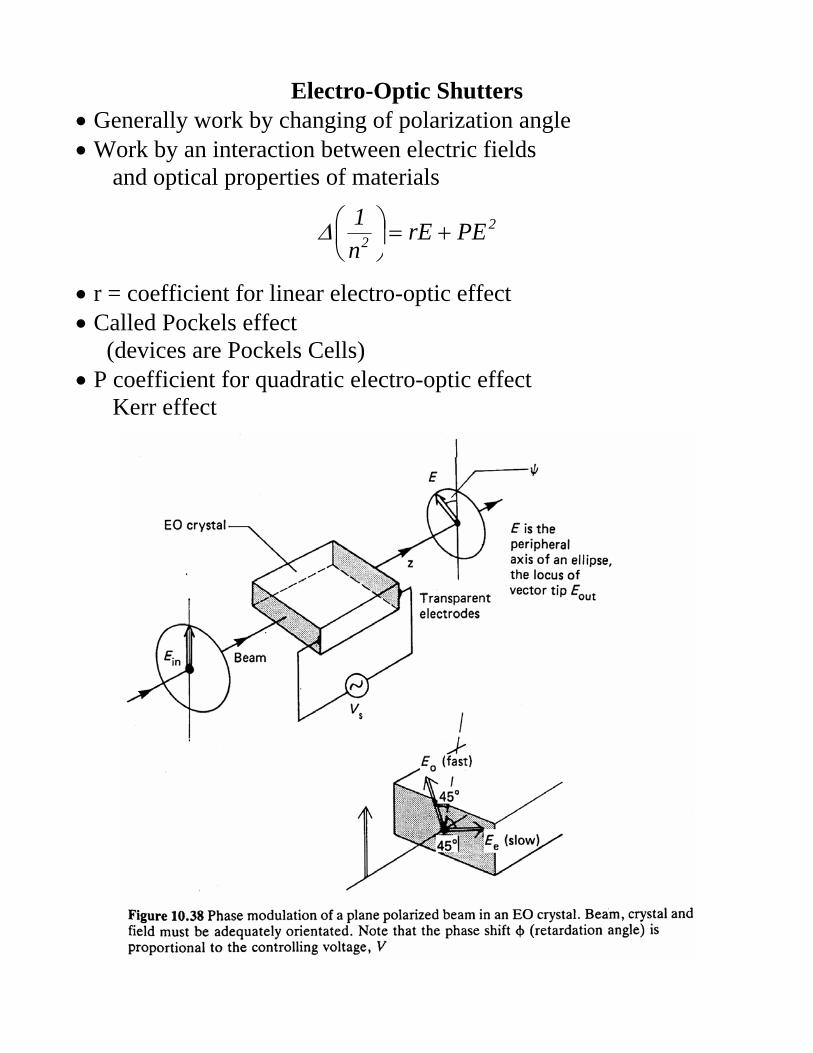
Electro-Optic Shutters • Generally work by changing of polarization angle • Work by an interaction between electric fields and optical properties of materials
22 PErE
n1
+=⎟⎠⎞
⎜⎝⎛∆
• r = coefficient for linear electro-optic effect • Called Pockels effect (devices are Pockels Cells) • P coefficient for quadratic electro-optic effect Kerr effect

Pockels Cell • Get a Change in Polarization with E field
Ern21nnn 3
00 ±=−=∆
• Changes are different in different axis
Ern21nnn 3
00x +=−=∆
Ern21nnn 3
00y −=−=∆
• This creates an effect called birefringence • Assuming a parallel plate capacitor length l with voltage V
lVE =
lVrnnn 3
0yx =−
• Thus phase shift due to light speed change in different directions • Total shift φ a function of cell length L light travels in
( ) LlVrn2Lnn2 3
0yx λπ
λπϕ =−=
• Note V is often applied perpendicular to light so L & l different However in some cells (as in diagram) L & l are the same

Electro-Optic Shutter • Typical materials: KDP Potassium Dihydrogen Phosphate KD*P Deuterated Potassium Dihydrogen Phosphate LiNbO3 Lithium Niobate LiTaO3 Lithium Tantulate • Also GaAs • Best currently KD*P get 90% rotation good for Argon Ion multiline • Note must carefully adjust offset voltages and swing voltages • Typical values 200 - 1000 V • Makes a good fast switch speed limited by speed of amplifier • typical values 2 microsec rise time faster (picosec) for special shutters/amplifiers

Electro-Optic Shutter • Take in polarized light • Polarizer on output • For high power use Brewster reflecting Polarizer

Diffraction Gratings Type Deflectors • Diffraction gratings created by many systems eg acousto-optic deflectors • Recall the Interference from a single slit width b seen at a long distance (Fraunhofer)
( )λ
θπββ
ββ )sin(b)sin(II2
0 =⎥⎦
⎤⎢⎣
⎡=
θ = angular deviation of pattern from minimum • For zeros: πβ N±= • If have several slits then waves from each interfere • More slits narrower beams

Diffraction Gratings • Now consider N slits with b spaced distance d apart • Get the diffraction pattern from each slit • But the diffraction patterns interfere

Diffraction Gratings Formulas • Similar to the single slit the intensity becomes
( ) ( )( ) λ
θπγγγ
βββ )sin(d
sinnsin)(sinII 2
2
2
2
0 =⎥⎦
⎤⎢⎣
⎡⎥⎦
⎤⎢⎣
⎡=
• Principal Maximums occur at
dm)sin( λθ =
where m = any integer, order of the diffraction • The maxima vary with the single slit β function

Diffraction Gratings as Deflectors • For large N gratings the Principal Maxima are narrow angles • Hence beams deflected to specific angles • Can create deflector by selecting beam angle

Acousto-Optic Deflectors • Consider a material whose index of refraction is significantly changed by acoustic waves • Eg. Lithium Niobate, quartz • A piezoelectric transducer attached to one end • Apply ultrasonic waves, eg 40 MHz creates a diffraction grating from index changes wavelength λs

Acousto-Optic Deflectors • If beam enters crystal at angle θ • The it will be deflected constructively when
λθλ m)sin(2 s =
where m is any integer • Typical defection is about 0.5 degrees • Use slits to select only the desired beam • Called a Bragg Cell (Angle for only one output is Bragg angle)

Acousto-Optic Analogue Modulators • Use the Bragg Cell for deflections • Focus output through a slit • By deflecting beam change intensity through slit • Focus light from slit into parallel beam

Deflectors as Q Switches • Recall pulsed pumped lasers • Laser pulse starts when threshold exceeded • Continues until below threshold • However could get much high pulse intensity if delay lasing beyond threshold • Do this by detuning cavity (Q switching) • Result is very powerful short pulse • However total power lower than without Q switch

Q Switch in Cavity • All methods involve putting something in cavity • Mechanical shutters, Electro-optic and Acousto-optic modulators used • Deflect or eliminate beam (i.e. low Q) pulse peak of pop inversion • Pulse synchronized with pump pulse end/centre

Acousto-Optic Q Switch • Deflector placed at an angle in cavity • Deflects beam with ultrasound applied

Saturable Absorber Q Switch • Saturable absorbers are solid state Q switches • Dyes which absorb until reach certain light intensity • Above threshold absorption loss suddenly decreases • Does not need any control system • Dye selected for the need.