DEFENSE INFORMATION SYSTEMS AGENCY - MindMeister
43
DEFENSE INFORMATION SYSTEMS AGENCY P.O. BOX 4502 ARLINGTON, VIRGINIA 22204-4502 DISA CIRCULAR 310-55-1* 21 January 2000 Last reviewed on 7 May 2009 OPERATIONS Status Reporting 1. Purpose. This Circular prescribes instructions for status reporting from the field to the Defense Information Systems Agency (DISA) of the transport layer of the Defense Information Infrastructure (DII). 2. Applicability. This Circular applies to DISA, the military departments, and other activities of the Department of Defense or governmental agencies that command, control, operate, maintain, or use the facilities and services of the DII. 3. Authority. This Circular is published in accordance with the authority contained in DOD Directive 5105.19, Defense Information Systems Agency (DISA), 25 June 1991. 4. Definitions. Definitions for terms used in this Circular follow the table of contents. 5. Reporting Requirements. Reporting requirements of this Circular are assigned Reports Control Symbol (RCS): DD- DISA(AR)055-1. This RCS need not be included in the status reports. FOR THE DIRECTOR: PAUL T. HAUSER Captain, USN Chief of Staff
Transcript of DEFENSE INFORMATION SYSTEMS AGENCY - MindMeister

DEFENSE INFORMATION SYSTEMS AGENCY P.O. BOX 4502
ARLINGTON, VIRGINIA 22204-4502
DISA CIRCULAR 310-55-1* 21 January 2000Last reviewed on 7 May 2009
OPERATIONS
Status Reporting
1. Purpose. This Circular prescribes instructions for status reporting from the field to the Defense Information Systems Agency (DISA) of the transport layer of the Defense Information Infrastructure (DII).
2. Applicability. This Circular applies to DISA, the military departments, and other activities of the Department of Defense or governmental agencies that command, control, operate, maintain, or use the facilities and services of the DII.
3. Authority. This Circular is published in accordance with the authority contained in DOD Directive 5105.19, Defense Information Systems Agency (DISA), 25 June 1991.
4. Definitions. Definitions for terms used in this Circular follow the table of contents.
5. Reporting Requirements. Reporting requirements of this Circular are assigned Reports Control Symbol (RCS): DD-DISA(AR)055-1. This RCS need not be included in the status reports.
FOR THE DIRECTOR:
PAUL T. HAUSER Captain, USN Chief of Staff

SUMMARY OF SIGNIFICANT CHANGES. This revision contains administrative changes reflecting organizational name and code changes. Chapter 6, AUTOSEVOCOM Reporting, has been replaced by Defense Red Switch Network Reporting. The Defense Data Network Reporting requirements which were in chapter 7 have been deleted. __________
*This Circular cancels DISAC 310-55-1, 3 October 1989 OPR: OP DISTRIBUTION: R
Continue to: Table of Contents List of Definitions Return to: Top of DISAC 310-55-1 Publication Listing DISA Home Page
[email protected] - Last change: 12 January 2000

CONTENTS
BASIC CIRCULAR
1. Purpose 2. Applicability 3. Authority 4. Definitions 5. Reporting Requirements
DEFINITIONS OF TERMS
C1. CHAPTER 1. STATUS REPORTING SYSTEM
C1.1 Objectives C1.2 Nonformatted Report (NR) C1.3 Formatted Report (FR) C1.4 Report Submission Requirements C1.5 Special Interest (SI) Items C1.6 High Interest Telecommunications (HIT) Items C1.7 Restoration of SI and HIT Items C1.8 Hazardous Condition (HAZCON) C1.9 Report Processing C1.10 Reporting Guides C1.11 Additional Reporting Guidance
C2. CHAPTER 2. FORMATTED REPORT INFORMATION LINES
C2.1 Use C2.2 Quality of Status Reporting C2.3 General Requirements C2.4 Order of Report Information Lines C2.5 Source of Information Items C2.6 Formatting Guidelines and Examples
C3. CHAPTER 3. REASON FOR OUTAGE (RFO) CODES
C3.1 Use C3.2 Cause or Symptom Codes (1st Position) C3.3 Outage Location Codes (2nd, 3rd, and 4th Positions) C3.4 Cause or Symptom Decodes (1st Position) C3.5 Outage Location Decodes (2nd, 3rd, and 4th Positions) C3.6 Remarks
C4. CHAPTER 4. OVERSEAS DEFENSE SWITCHED NETWORK REPORTING

C4.1 Purpose C4.2 Special NR Reporting Requirements
C5. CHAPTER 5. AUTODIN REPORTING
C5.1 Purpose C5.2 Special NR Reporting Requirements C5.3 Special FR Reporting Requirements
C6. CHAPTER 6. DEFENSE RED SWITCH NETWORK REPORTING
C6.1 Purpose C6.2 Definitions C6.3 Classified Information
C7. CHAPTER 7. [RESERVED]
C8. CHAPTER 8. DEFENSE SATELLITE COMMUNICATIONS SYSTEM REPORTING
C8.1 Purpose C8.2 Definitions C8.3 Special Reporting Conditions C8.4 Special NR Reporting Requirements C8.5 Special FR Reporting Requirements
C9. CHAPTER 9. TECHNICAL DETAILS
C9.1 Purpose C9.2 Line Format C9.3 Error Checking
ILLUSTRATIONS
Table T1.1 TABLE 1. Summary of Reportable Conditions
Continue to: CHAPTER 1. STATUS REPORTING SYSTEM
Return to: Basic Circular Publication Listing DISA Home Page
[email protected] - Last change: 12 January 2000

DEFINITIONS
Access Facility. The initial reporting or reported-on facility servicing the user of a circuit.
Channel. That portion of a trunk used to carry intelligence between the terminal points of the trunk.
Circuit. A communications capability between two or more users, a user terminal and a switching facility, or between two switching facilities.
Circuit Outage. The loss of service provided by a circuit, in either or both directions. A circuit outage is over when service is restored.
Hazardous Condition (HAZCON). A condition applicable to reporting and reported-on facilities and links, under which the loss or severe degradation of service is imminent.
Higher-Level Outage. See lower-level outage.
High Interest Telecommunications (HIT) Items. Those circuits and trunks which are permanently designated to be reported to allow continuous management attention.
Interswitch Trunk. A circuit connecting two switching facilities in a switched network.
Isolation. Loss of all external connectivity at a facility. The isolation is ended when the first circuit, other than an orderwire, is restored to provide customer service. Isolations due to a failure internal to a facility should only be reported as a facility outage.
Link. A transmission path operating between two successive equipment locations. In cable facilities, equipment locations are those points where cables terminate or branch. In radio systems, equipment locations are RF repeaters, transmitters, or receivers. A link consists of one or more trunks.
Link Outage. The loss of service on all trunks and channels of a transmission path. A link outage will be reported if the link becomes unusable because of the failure of link equipment (e.g., loss of combiner, antenna, or waveguide), but not because of the loss of traffic due to failure not associated with the link. For analog multiplex equipment, a link outage should also be

reported if the link becomes unusable because of multiplex or baseband cable failure. For example, loss of the analog multiplex equipment associated with one end of a link would be reported as a link failure if all trunks and channels on the link were out. However, a tandem link which obtains all its traffic from the failed link would not be logged out. A link outage is over when the first circuit, exclusive of an orderwire, is available over the link to provide customer service.
Lower-Level Outage. Loss of service on links and trunks caused by a higher-level facility, link, or trunk outage. For example, an outage on a 12.6 Mbps trunk would cause an outage on all the 1.544 Mbps (lower-level) trunks which traverse the 12.6 Mbps (higher-level) trunk.
Reload. An AUTODIN operating procedure used to replace the current switch program by the original or by a new version.
Reporting Designator. A unique, three character alphanumeric grouping assigned to one or more facility codes at a geographical location, for the purpose of status reporting. Based on the type of facilities, more than one reporting designator may be assigned within a geographical location (base, post, camp, etc.) These designators are assigned by the appropriate DISA area, and published in each area's additional guidance to this Circular.
Reported-on Facility. Any facility assigned a reporting designator for which a reporting facility submits status reports.
Reporting Facility. Any facility assigned a reporting designator and tasked to submit formatted status reports to DISA.
Reporting or Reported-on Facility Outage. The loss of service on all links, trunks, and circuits due to an internal problem. A facility outage occurs when the reporting or reported-on facility fails; e.g., a total power failure. The facility outage is over when the first circuit, exclusive of an orderwire, is available to provide customer service. Additional definitions for network and satellite facility outages are contained in the appropriate chapters.

Reroute. The restoral of a circuit via an alternate transmission path during a period when the normal transmission path has failed. A reroute may be preengineered.
Restart. An AUTODIN message switch operating procedure used to return to the beginning of, and to reperform, any cycle in which an error or interrupt occurred.
Special Interest (SI) Item. A circuit or trunk placed on an SI list for a limited time when special reporting is required to identify the cause and/or location of a problem.
Subscriber. A term used to identify a directly connected user terminal of any of the switched networks.
Trunk. A communications path between two terminal facilities, at which channels are available to be tested, rerouted, dropped out, or switched to another route. A trunk consists of one or more channels.
Trunk Outage. When all channels of the trunk are unusable and not available for service. The outage is over when the first channel, other than one used for an orderwire, is returned to a usable condition, and is available for service.
User. Any organization, unit, office, or individual that has equipment connected to a circuit, and uses the DII for communications purposes. (See also Subscriber.)
User or Subscriber Outage. The loss of service between users, or between a network switch and a subscriber, in either or both directions, because of a transmission facility outage between the user or subscriber and the access facility, or an outage at the user or subscriber terminal, or any other outage which cannot be attributed to a transmission facility.
Continue to: CHAPTER 1 STATUS REPORTING SYSTEM
Return to: Basic Circular Table of Contents Publication Listing DISA Home Page
[email protected] - Last change: 12 January 2000

C1. CHAPTER 1. STATUS REPORTING SYSTEM
C1.1 Objectives. The status reporting system is structured to provide management information to DISA and the operation and maintenance (O&M) elements to obtain:
C1.1.1 Current information from near-real-time nonformatted reports for exercising operational direction and control.
C1.1.2 Historical information from daily formatted reports for conducting computer assisted performance analysis.
C1.2 Nonformatted Report (NR). A telephonic (or orderwire) report of status is required as soon as feasible after a reportable event occurs, since this information is used for operational direction and control by the DII Operations Control Complex (DOCC) elements. An NR should be submitted to the next level in the reporting chain (reporting facility, Regional Network Operations and Security Center (RNOSC), etc.) within 10 minutes on the following conditions:
C1.2.1 All reporting or reporting-on facility outages of 1 minute or longer.
C1.2.2 A link outage of 10 minutes or longer.
C1.2.3 Outages of the specified duration on a Special Interest (SI) trunk or circuit designated for nonformatted reporting. Not all SI trunks or circuits may require nonformatted reporting.
C1.2.4 Outages of the specified duration on those High Interest Telecommunications (HIT) items which require nonformatted reporting.
C1.2.5 Occurrence and changes in the status of the following subjects:
C1.2.5.1 A hazardous condition (HAZCON) which has existed for 30 minutes.
C1.2.5.2 Isolation of 1 minute or longer of a reporting or reported-on facility, a Commander in Chief (CINC), an embassy, or a unified command headquarters.
C1.2.6 Special conditions for the networks as stated in their specific chapter.

C1.3 Formatted Report (FR). An FR provides information which is used for computer assisted historical analysis of the performance. The information is required in a specific format so that computers can automatically process the data. At least one FR with a cutoff time of 2400Z must be submitted each raday. DISA areas may direct submission of additional FRs, as required. FRs may be submitted by reporting facilities anytime during the raday (to reduce the size of the 2400Z report, etc.) All reported outages must be at least 1 minute long. Once initially reported, the item must be reported until the condition is cleared (see paragraph C1.8 for HAZCONs and subparagraph C2.3.5 for outages). Times given below are the minimum required by DISA, but shorter durations may be reported by any facility. The following conditions will be reported by an FR:
C1.3.1 All reporting or reported-on facility outages of 1 minute or longer.
C1.3.2 All link outages of 1 minute or longer.
C1.3.3 High interest and special interest trunk and circuit outages of 10 minutes or longer.
C1.3.4 Open HAZCONs which have existed for 24 hours or more at the time of report submission.
C1.3.5 Additional special conditions for the AUTODIN network as contained in chapter 5.
C1.4 Report Submission Requirements.
C1.4.1 Table T1.1 provides a summary of reportable conditions. In general, the facility experiencing the reportable condition reports it. For link and trunk outages, the facility terminating the receive side must report it. If only a single terminating facility is tasked to report, both directions of transmission should be reported by that facility. Reportable access line outages should be reported by the access facility. Other reportable circuit outages should be reported by the receive side facility.
C1.4.2 For links and trunks, an FR should not be submitted if a higher-level outage has been reported. For example, if a link fails, the resulting trunk outages will be automatically generated by the DOCC computer. Hence, only the higher-level outage need be reported. However, HIT and SI trunks restored to

service through alternate routing must be reported with an OUT/IN report: the OUT time being the higher level outage time and the IN time being the time service is restored on the alternate path.
C1.5 Special Interest (SI) Items.
C1.5.1 Description. Special interest items (circuits or trunks) are those which require special formatted reporting for identification of problem areas. Special nonformatted reporting may also be required when warranted.
C1.5.2 Analysis of Special Interest Items.
C1.5.2.1 A RNOSC may place a trunk on the special interest lists for identification of problem areas. For circuits, the Communications Control Office (CCO) or the Communications Management Office (CMO) and/or the user should initiate the request to DISA. The requester should identify the problem(s) experienced to justify the SI designation. All analysis data will be taken from the FR files at the DISA area.
C1.5.2.2 The DISA Global Network Operations and Security Center (GNOSC) will be the authority for placing interarea trunks and circuits on SI lists.
C1.5.2.3 Items will be removed from the SI category after 3 months unless their retention is justified by the requester.
C1.5.2.4 Each DISA area will send an advisory message to all effected locations on an as-required basis (at least quarterly), listing all their current special interest items.
C1.5.3 Feedback Products. Feedback information requirements should be discussed with the appropriate DISA area to determine which products are available and required and the necessary formal procedures to obtain the information.
C1.6 High Interest Telecommunications (HIT) Items. HIT items may be circuits or trunks. They require continual reporting for trending, to facilitate providing operational direction, or to provide command attention. Reportable HIT items:
C1.6.1 DISA Headquarters designated trunks and circuits are shown in table T1.1. Items on this list have either worldwide command interest or support critical command and control missions.

C1.6.2 Each RNOSC may place intra-area trunks and circuits on their area HIT list. This list will contain only those HIT items considered critical by the respective CINC or DISA area commander.
C1.7 Restoration of SI and HIT Items. Procedures for restoring items designated SI or HIT will be in accordance with the assigned Telecommunications Service Priority (TSP) System restoration priority, and are not altered by designation as SI or HIT. Such designation changes only the reporting requirements, and does not ensure more rapid restoral.
C1.8 Hazardous Condition (HAZCON). Although declaration of a HAZCON is discretionary, it must be viewed as an urgent notification of a major problem that has occurred or is projected to occur. If the individual responsible for making the decision is not sure whether or not a HAZCON exists, the RNOSC should be contacted to assist in the determination. The estimated time of termination of the HAZCON should be reported within 5 working days after the HAZCON is established. The following guidelines are to be used to determine if a HAZCON should be reported:
C1.8.1 Partial or complete evacuation of a facility.
C1.8.2 Loss of diversity on a radio link (i.e., space, frequency, or polarization.)
C1.8.3 Failure of any combination of primary, backup, or spare communications equipment or power facilities, when failure of another like component would lead to severe degradation or cause a link or facility outage, and sufficient equipment to sustain or restore operation is not immediately available.
C1.8.4 Loss of environmental equipment when immediate restoral is not possible, but is necessary for continued link or facility operation.
C1.8.5 Specific network conditions as detailed in the following chapters.
C1.8.6 Other situations or conditions which, in the opinion of the shift supervisor or designated responsible individual, could result in a link or facility outage.
C1.9 Report Processing.

C1.9.1 NRs will be forwarded to the appropriate DOCC element over the DOCC critical control circuits, or by telephone. Each DOCC element will screen the reports and provide the following to the next higher DOCC element:
C1.9.1.1 Information specified by the appropriate supplements to this Circular.
C1.9.1.2 Requests for assistance in resolving problems which cannot be resolved locally.
C1.9.1.3 Any other information not specifically covered in this Circular or supplements thereto, which is required for the proper exercise of operational direction and control.
C1.9.2 FRs will be sent as specified by the appropriate DISA area.
C1.10 Reporting Guides. Each DISA area will publish appropriate Reporting Guides, for each reporting and reported-on facility, to identify those links, trunks, and circuits which terminate or pass through the facility codes assigned to each reporting designator. Corrections to the reporting guide should be submitted as directed by the appropriate DISA area.
C1.10.1 An updated reporting guide will be prepared for, and distributed to, each reporting facility at least twice yearly.
C1.10.2 Reporting guides prepared for manned reported-on facilities will be distributed by the reporting facility. Deviation from this guidance is only authorized when mutually agreed upon by the DISA area and the O&M activities.
C1.11 Additional Reporting Guidance. The reporting structure and unique reporting requirements will be published, as required, by each DOCC element. The additional guidance should not repeat information contained in this Circular and must be forwarded to the Director, DISA, ATTN: D3, for review and approval before implementation. Changes or modifications of area reporting hierarchy (designation of reporting and reported-on facilities) need not be submitted for prior approval.
Continue to: TABLE T1.1. SUMMARY OF REPORTABLE CONDITIONS CHAPTER 2. FORMATTED REPORT INFORMATION LINES
Return to:

Basic Circular Table of Contents List of Definitions Publication Listing DISA Home Page
[email protected] - Last change: 12 January 2000

TABLE T1.1 SUMMARY OF REPORTABLE CONDITIONS
Condition (Reportable Duration in Minutes) Nonformatted FormattedIsolation 1 - Facility Outage 1 1
Link Outage (Note 1) 10 1
HIT Trunk Outages (Note 1) Digital 1.544 Mbps and higher
(Type trunk code "N") 30 10
DSCS (Type trunk code "S") 30 10
HIT Circuit Outages AUTODIN ISTs (Note 2) 10 10 AUTODIN Subscribers (Notes 2, 3) - 10
DRSN ISTs (Notes 2,4) - 10
DSN ISTs (Notes 1, 2) - 10 Special Networks (Note 5) 10
Special Interest (SI) Outages (Note 6) (Note 5) 10 HAZCON (Note 7) 30 1440 Footnotes:
1. Outages need not be reported if they result from a reportable higher level trunk, link, or facility outage.
2. Outages need not be reported if they are caused by a reportable switch outage.
3. Only the serving AUTODIN Switching Center (ASC) should submit formatted AUTODIN subscriber access line outage reports.
4. CONUS DRSN reporting will be done by the DRSN monitoring center at Scott AFB.
5. Specific items and times will be identified by the appropriate DISA area at least quarterly.
6. All formatted reports on SI items must include explanatory remarks. These remarks must provide additional information and not decode the Reason For Outage (RFO) code used.
7. Limit HAZCON reports to unclassified information only. Supplemental classified information should be passed via secure means directly to those with the need-to-know.
Continue to: CHAPTER 2. FORMATTED REPORT INFORMATION LINES
Return to: Basic Circular Table of Contents List of Definitions Publication Listing DISA Home Page
[email protected] - Last change: 12 January 2000

C2. CHAPTER 2. FORMATTED REPORT INFORMATION LINES
C2.1 Use. Report information lines described in this chapter are required for submission of specific status information. Strict adherence to the prescribed format is required to ensure complete understanding of the reports and to enable the reports to be computer processed without human intervention.
C2.2 Quality of Status Reporting. The quality of status reporting is determined by the timeliness, accuracy, and completeness of reports. DISA determines the quality of status reporting by performance evaluations and review of statistical data. Each DISA RNOSC will review status reports originated by reporting facilities within its area of responsibility and provide timely, periodic error analysis to O&M activities in an effort to reduce reporting errors and increase the accuracy of formatted reports.
C2.3 General Requirements.
C2.3.1 Each information line must:
C2.3.1.1 Begin with the appropriate information line symbol.
C2.3.1.2 Adhere strictly to the prescribed format.
C2.3.1.3 Contain a slant bar (/) to separate adjacent data elements.
C2.3.1.4 Use four digit universal (Zulu) time throughout.
C2.3.1.5 Contain no spaces, blanks, carriage returns, or line feeds within or between data elements, except within the remarks portion.
C2.3.1.6 Contain no more than 69 characters.
C2.3.2 The following information line symbols must be used:
Symbol Name/Description
(((( Opening Parens. A series of four opening parentheses begin the report. These symbols must be placed on a separate information line.
S S-line. Identifies the reporting facility submitting the report, and/or the reporting

or reported-on facility with which subordinate lines are associated.
L L-line. Identifies link information.
K K-line. Identifies trunk information.
U U-line. Identifies user/circuit information.
/ Slant Bar. Separates data elements.
OUT Out Time Indicator. Identifies the start time of a reportable outage.
IN In Time Indicator. Identifies the time the reportable outage ended.
RMKS Begin Remarks Indicator. Identifies the beginning of narrative remarks. No format verification is used between the Begin and End Remarks indicators.
XXXX End Remarks Indicator. Identifies the end of narrative remarks. All four Xs must appear together on the same line.
)))) Closing Parens. A series of four closed parentheses end the report. These symbols must be placed on a separate information line.
C2.3.3 In each formatting guideline provided in paragraph C2.6, both the OUT and IN times are shown on the same information line. However, these times may be reported individually on separate information lines, and either in the same or in a different report. If an OUT report has previously been reported, and a subsequent restoral and failure are to be reported, the IN time will have to be on a separate line from the OUT time. Under no circumstances should the IN time of one outage and the OUT time of a subsequent outage be placed on the same line (e.g., IN0100/OUT0105 is incorrect.) Two separate lines are required to report this information.
C2.3.4 The report information line symbol "RMKS" is mandatory when certain RFO codes are used, and when explanatory narrative or HAZCON information is reported. The slant bar and Begin Remarks Indicator (/RMKS) must immediately follow the last character of the information line, with no prior spaces, or
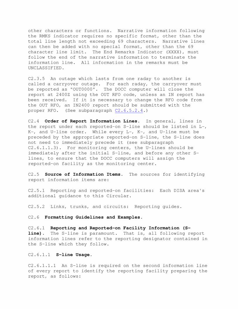
other characters or functions. Narrative information following the RMKS indicator requires no specific format, other than the total line length not exceeding 69 characters. Narrative lines can then be added with no special format, other than the 69 character line limit. The End Remarks Indicator (XXXX), must follow the end of the narrative information to terminate the information line. All information in the remarks must be UNCLASSIFIED.
C2.3.5 An outage which lasts from one raday to another is called a carryover outage. For each raday, the carryover must be reported as "OUT0000". The DOCC computer will close the report at 2400Z using the OUT RFO code, unless an IN report has been received. If it is necessary to change the RFO code from the OUT RFO, an IN2400 report should be submitted with the proper RFO. (See subparagraph C2.6.5.2.4.)
C2.4 Order of Report Information Lines. In general, lines in the report under each reported-on S-line should be listed in L-, K-, and U-line order. While every L-, K-, and U-line must be preceded by the appropriate reported-on S-line, the S-line does not need to immediately precede it (see subparagraph C2.6.1.1.3). For monitoring centers, the U-lines should be immediately after the initial S-line, and before any other S-lines, to ensure that the DOCC computers will assign the reported-on facility as the monitoring center.
C2.5 Source of Information Items. The sources for identifying report information items are:
C2.5.1 Reporting and reported-on facilities: Each DISA area's additional guidance to this Circular.
C2.5.2 Links, trunks, and circuits: Reporting guides.
C2.6 Formatting Guidelines and Examples.
C2.6.1 Reporting and Reported-on Facility Information (S-line). The S-line is paramount. That is, all following report information lines refer to the reporting designator contained in the S-line which they follow.
C2.6.1.1 S-line Usage.
C2.6.1.1.1 An S-line is required on the second information line of every report to identify the reporting facility preparing the report, as follows:

SABC/2/012400
C2.6.1.1.1.1 S: S-line indicator.
C2.6.1.1.1.2 ABC: Reporting facility designator.
C2.6.1.1.1.3 2: Report sequence number. FRs should be sequentially numbered beginning with number 1 for the first report of each raday.
C2.6.1.1.1.4 012400: Report cutoff date-time. The calendar date of the reported items, immediately followed by the zulu time of the report cutoff. No times within the report may be later than the report cutoff time.
C2.6.1.1.2 An S-line is used to report a facility outage and restoral:
SDEF/OUT0745/IN0755/RFO1
C2.6.1.1.2.1 SDEF: S-line indicator and reporting designator of the facility that experienced the outage.
C2.6.1.1.2.2 OUT0745/IN0755: OUT and IN times (zulu).
C2.6.1.1.2.3 RFO1: Reason for outage (RFO) code as shown in chapter 3. The RFO location must be the reporting designator for the S-line (DEF in this case.)
C2.6.1.1.3 An S-line is required to identify information in subsequent information lines as being from a facility. All following information lines until the next S-line will be in reference to this facility's designator. In the absence of any other S-line for the facility, only the S-line indicator and the reported-on reporting designator are placed on the information line. In the following example, the facility reporting the link OUT (receive facility) is ABC for M2111, DEF for M2222, and GHI for link M2333.
SABC/01/032400 LM2111/OUT1000/IN1100/RFO1 SDEF LM2222/OUT0800/IN0900/RFO2 SGHI/OUT1000/IN1010/RFO3/RMKS LOST COMMERCIAL POWER, MANUALLY STARTED BACKUP XXXX LM2333/OUT1300/IN1500/RFO4

C2.6.1.1.4 An S-line is used to report narrative status information concerning a reporting or a reported-on facility. For example, to report narrative information on facility DEF, the information line would be:
SDEF/RMKS Narrative XXXX
C2.6.1.1.5 An S-line is used to report a facility HAZCON. The HAZCON identifier HAZ is placed immediately after the reporting designator on the S-line. For example, a HAZCON on facility DEF would be reported:
SDEFHAZ/RMKS Narrative XXXX
C2.6.1.2 Negative Reports. The following illustrates a minimum, or negative, report for reporting facility CBA. Negative reports for reported-on facilities are not required.
(((( SCBA/1/032400 ))))
C2.6.1.3 Report Posting. Facility outage and restoral reports are automatically posted by DOCC computers to all links and trunks terminating at, or traversing, the affected facility. Consequently, these lower-level link and trunk outages do not need to be reported, unless the outage extends beyond the facility restoral time.
C2.6.2 Link Information Line (L-line). An L-line must be preceded by an S-line to indicate the reporting designator of the receive facility which terminates the link being reported. If the receive facility is a reported-on facility, its reporting designator must be included as shown in subparagraph C2.6.1.1.3.
C2.6.2.1 Use of an L-line.
C2.6.2.1.1 An L-line is used to report a link outage and restoral. For example, to report an outage on the receive side (ABC) of link T0123:
SABC LT0123/OUT1350/IN1425/RFO1
C2.6.2.1.1.1 SABC: Identification of receive facility.
C2.6.2.1.1.2 LT0123: L-line indicator and link number.

C2.6.2.1.1.3 OUT1350/IN1425: OUT and IN times (zulu).
C2.6.2.1.1.4 RFO1: RFO code from chapter 3. If the location code is a reporting designator, it must be one of the terminals of the link.
C2.6.2.1.2 An L-line is used to report narrative status information concerning a link. For example:
LT1026/RMKS Narrative XXXX
C2.6.2.1.3 An L-line is required to report a link HAZCON. It must be reported under the S-line of the location of the problem. The HAZCON identifier HAZ is placed immediately after the link identifier on the L-line. For example:
LT3214HAZ/RMKS Narrative XXXX
C2.6.2.2 Report Posting. Reported link outages and restorals are automatically posted by DOCC computers to all trunks traversing the reported link.
C2.6.2.3 Reports on Single-Trunk Links. Outages and restorals of links consisting of a single trunk should be reported by L-line, rather than by K-line, if the outage is caused by link problems and not trunk equipment. This allows lower-level outages to be generated by the DOCC computers.
C2.6.3 Trunk Information Line (K-line). A K-line must be preceded by an S-line to indicate the reporting designator of the receive facility which terminates the trunk experiencing the outage. If the receive facility is reported-on, its reporting designator must then be included as shown in subparagraph C2.6.1.1.3.
C2.6.3.1 A K-line is used to report a trunk outage and restoral. For example, an outage on the receive side (GHI) of trunk 77UN01 would be reported:
SGHI K77UN01/OUT1530/IN1545/RFO1
C2.6.3.2 A K-line is used to report narrative status information concerning a trunk. For example:
K77UN01/RMKS Narrative XXXX

C2.6.4 User Information Line (U-Line).
C2.6.4.1 A U-line is used to report the failure and/or restoral of a user terminal, a circuit outage and/or restoral between the user and the nearest DII access facility. Circuits restored to service through alternate routing must be individually reported "IN" as of the time service is restored on the alternate path. There are four ways to identify a circuit on an outage report. Which technique is used depends on the number of separate paths a circuit has. Every reportable circuit has a Command Communications Service Designator (CCSD) and a Service Availability (SA) code. The last four characters of the CCSD are called the circuit number.
C2.6.4.1.1 U-line Outage Report Formats.
C2.6.4.1.1.1 When the circuit has an SA of "A" and the circuit number uniquely identifies it (one CCSD), only the circuit number needs to be reported. For example, if circuit ABCD1234 (which is the only CCSD for circuit number 1234) with an "A" SA failed, it would be reported:
U1234/OUT0500/IN0630/RFO1
C2.6.4.1.1.2 When the circuit has an SA of other than "A" and the circuit number uniquely identifies it (one CCSD), only the circuit number and the SA need to be reported. For example, if circuit ABCD1234 failed on the "H" SA path, the report would be:
U1234/H/OUT0500/IN0630/RFO1
C2.6.4.1.1.3 When the circuit number does not uniquely identify the circuit (more than one CCSD for the circuit number), and the circuit being reported has an "A" SA, report the full CCSD. For example, if circuit ABCD4321 had an outage on the "A" SA path, and circuit DCBA4321 also existed, the outage on ABCD4321 would be reported:
UABCD4321/OUT0500/IN0630/RFO1
C2.6.4.1.1.4 When a circuit has an SA code other than "A" and the full CCSD is required to uniquely identify the circuit, report both the CCSD and the SA. For example, if circuit ABCD4321 had two SAs (e.g.,"A" and "G"), and circuit DCBA4321 also existed, an outage on ABCD4321 with the SA of "G" would be reported:

UABCD4321/G/OUT0500/IN0630/RFO1
C2.6.4.1.2 Format Selection. While the example shown in subparagraph C2.6.4.1.1.4 could be used for all circuits, only the minimum to uniquely identify the circuit should be used. For example, the majority of circuits can be reported using only the circuit number (subparagraph C2.6.4.1.1.)
C2.6.4.2 A U-line is used to report narrative status information concerning a circuit. For example:
UABCD1234/RMKS Narrative XXXX
C2.6.5 Status Report Correction Techniques. Status report errors can be format or factual (content) errors.
C2.6.5.1 Format Errors. Format errors are caused by missing or out of sequence information on a line, or an improper form of information in a line segment. These errors are identified by the DOCC computers and can be corrected only by the RNOSC. Upon discovery of format errors, the reporting facility will be informed by the appropriate DOCC element, which will issue appropriate instructions.
2.6.5.2 Factual Errors. Factual errors include reporting an incorrect time, a different CCSD or link identifier than intended, and similar items. If a trunk or link is incorrectly reported OUT by a facility which is not the receive terminal, the RNOSC must be contacted to correct the error. Other errors can be erased by canceling the condition of the erroneous entry. However, in all cases, the correct information must be submitted after error erasure. When a report is submitted to cancel an erroneous time, the RFO code must be the same as the RFO code in the report being corrected. However, the report with the correct time can have a different RFO code.
C2.6.5.2.1 If an OUT report time is erroneous, submit an IN report using the same RFO code, with the IN time identical to the erroneous OUT time. For example:
OUT time error: K11UN07/OUT0720/RFO1 Cancellation: K11UN07/IN0720/RFO1 Correct OUT time: K11UN07/OUT0820/RFO1
C2.6.5.2.2 If an IN report time is erroneous, submit an OUT report using the same RFO code, with the OUT time identical to the erroneous IN time. For example:

IN time error: K18US03/IN2134/RFO1 Cancellation: K18US03/OUT2134/RFO1 Correct IN time: K18US03/IN2143/RFO2
C2.6.5.2.3 If an OUT/IN report contains erroneous time information, the error must be canceled as explained above. That is, an IN report is used to cancel an erroneous OUT time, and a separate OUT report is used to cancel an erroneous IN time. An OUT, IN, or OUT/IN report must then be used to replace the canceled OUT, IN, or OUT/IN information. For example:
OUT/IN time error: K35JN06/OUT0902/IN1543/RFO1 Cancellation: K35JN06/IN0902/RFO1 Cancellation: K35JN06/OUT1543/RFO1 Correction: K35JN06/OUT0920/IN1435/RFO1
C2.6.5.2.4 To correct an RFO code, the following procedures must be used. Since RFO codes reported on IN reports always replace RFO codes reported on OUT reports during computer processing, it is not necessary to correct an erroneous OUT report RFO code, unless no IN report is submitted during the remainder of the raday. If this is the case, an IN report (using 2400Z as the IN time) with the correct RFO code must be submitted. To correct an erroneous RFO code previously submitted by an OUT/IN or IN report, a new IN report (not OUT/IN) with the proper RFO code must be submitted. For example:
RFO code error: KBBUN28/OUT1000/IN1100/RFO1 Correction: KBBUN28/IN1100/RFO2
Continue to: CHAPTER 3. REASON FOR OUTAGE (RFO) CODES
Return to: Basic Circular Table of Contents List of Definitions Publication Listing DISA Home Page
[email protected] - Last change: 12 January 2000

C3. CHAPTER 3. REASON FOR OUTAGE (RFO) CODES
C3.1 Use. Reason for outage (RFO) codes are used to report the location and description of an outage. The four position code contains two parts.
C3.1.1 The first position code states the cause or symptom of the outage.
C3.1.2 The second through forth positions are the identifier for the location of the outage.
C3.2 Cause or Symptom Codes (1st Position).
C3.2.1 Codes for outages with a known cause and location:
C3.2.1.1 Authorized Outage--A. Outage due to a scheduled interruption. Preventive maintenance, authorized service interruption, scheduled quality control testing, and scheduled modifications are examples.
C3.2.1.2 Control Seizure/Coordination--C. Outage resulting from unscheduled testing when no problem or symptom is identified during testing. If the testing was requested by the user, the user location code should be used. This code should be used if an outage is extended due to higher priority work or coordination difficulty with other control facilities (military or commercial) or users. Also used for any outages resulting from a terminal not being available to test and/or return to service. (For part-time AUTODIN subscribers, see chapter 5.) Remarks are required when outages exceed 30 minutes.
C3.2.1.3 Electronic Equipment/Wiring--E. Outage due to faulty wiring or electronic equipment malfunction. For example, problems with a modem, crypto, signaling or conditioning equipment, distribution frame, radio, power supplies, etc. Remarks are required, specifying the exact item causing the outage.
C3.2.1.4 Facility Support Equipment--F. Outage caused by failure of the air-conditioning, heating, or any other environmental control equipment.
C3.2.1.5 Human Error/Procedural Error--H. Outage due to personnel not following proper procedures. Remarks required.
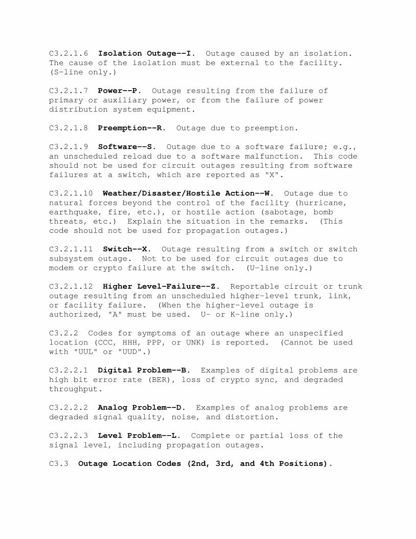
C3.2.1.6 Isolation Outage--I. Outage caused by an isolation. The cause of the isolation must be external to the facility. (S-line only.)
C3.2.1.7 Power--P. Outage resulting from the failure of primary or auxiliary power, or from the failure of power distribution system equipment.
C3.2.1.8 Preemption--R. Outage due to preemption.
C3.2.1.9 Software--S. Outage due to a software failure; e.g., an unscheduled reload due to a software malfunction. This code should not be used for circuit outages resulting from software failures at a switch, which are reported as "X".
C3.2.1.10 Weather/Disaster/Hostile Action--W. Outage due to natural forces beyond the control of the facility (hurricane, earthquake, fire, etc.), or hostile action (sabotage, bomb threats, etc.) Explain the situation in the remarks. (This code should not be used for propagation outages.)
C3.2.1.11 Switch--X. Outage resulting from a switch or switch subsystem outage. Not to be used for circuit outages due to modem or crypto failure at the switch. (U-line only.)
C3.2.1.12 Higher Level-Failure--Z. Reportable circuit or trunk outage resulting from an unscheduled higher-level trunk, link, or facility failure. (When the higher-level outage is authorized, "A" must be used. U- or K-line only.)
C3.2.2 Codes for symptoms of an outage where an unspecified location (CCC, HHH, PPP, or UNK) is reported. (Cannot be used with "UUL" or "UUD".)
C3.2.2.1 Digital Problem--B. Examples of digital problems are high bit error rate (BER), loss of crypto sync, and degraded throughput.
C3.2.2.2 Analog Problem--D. Examples of analog problems are degraded signal quality, noise, and distortion.
C3.2.2.3 Level Problem--L. Complete or partial loss of the signal level, including propagation outages.
C3.3 Outage Location Codes (2nd, 3rd, and 4th Positions).

C3.3.1 Reporting Designator. If the cause of the outage is within a facility that has been assigned a reporting designator, then that designator should be used for the location code. These designators are contained in each DISA area's additional guidance to this Circular.
C3.3.2 Commercial Facility--CCC. Used to identify any outage caused by failure of commercially leased services (path or equipment). Used in conjunction with any 1st position code except "A" or "C" to indicate the periods of outage chargeable to a commercial carrier. (DISAC 310-70-1, DII Technical Control, explains times chargeable to the commercial carrier.) Report commercial outage which is not chargeable using 1st position codes "A" or "C" to indicate "commercial authorized outage" or "commercial control seizure/coordination" respectively. However, to identify failures at a facility operated totally under contract, use the facility's reporting designator, not "CCC".
C3.3.3 Host Nation--HHH. Used for any outage caused by a Host Nation Defense Communications Network path or facility. Foreign country commercial carrier paths or facilities should be reported with "CCC" and not this code.
C3.3.4 Link Path--PPP. Used to identify the location between the two terminals of a link; e.g., path propagation, cable repeaters, etc. (Use only with L-lines, K-lines, or U-lines with a first position of "Z" or "A".)
C3.3.5 Unknown--UNK. Used when the outage location cannot be isolated. A first position symptom code must be used with this code. (Remarks are required.)
C3.3.6 Distant User/Access Line--UUD. Used when the outage occurs at the distant user location, or the distant user access line. (U-lines only. Not to be used for AUTODIN or DSN ISTs, or with symptom codes.)
C3.3.7 Local User/Access Line--UUL. Used when the outage occurs at the local user location, or the local user access line. (U-lines only. Not to be used for AUTODIN or DSN ISTs, or with symptom codes.)
C3.4 Cause or Symptom Decodes (1st Position).
Code Explanation

A Authorized outage.
B Digital problem. (Symptom: BER, Crypto sync, etc.)
C Control seizure/coordination. (Remarks required.)
D Analog problem. (Symptom: signal quality, etc.)
E Electronic equipment/wiring. (Remarks required.)
F Facility support equipment (Environment control.)
H Human error/procedural error. (Remarks required.)
I Isolation outage. (S-line only.)
L Level problem. (Symptom: propagation, etc.)
P Power.
R Preemption.
S Software.
W Weather/disaster/hostile action. (Remarks required.)
X Switch. (U-line only.)
Z Higher level failure. (K-line or U-line only.)
C3.5 Outage Location Decodes (2nd, 3rd, and 4th Positions).
Code Explanation
"---" Reporting designator of the outage location.
CCC Commercial facility.
HHH Host Nation.
PPP Link path. (Only L-line, K-line, or U-line with "A" or "Z".)
UNK Unknown. (Use only with codes "B", "D" or "L". Remarks required.)
UUD Distant user/access line. (U-line only.)

UUL Local user/access line. (U-line only.)
C3.6 Remarks. "Remarks" are required only on reports with an IN time. However, unclassified remarks can be added to any report.
Continue to: CHAPTER 4. OVERSEAS DEFENSE SWITCHED NETWORK REPORTING
Return to: Basic Circular Table of Contents List of Definitions Publication Listing DISA Home Page
[email protected] - Last change: 12 January 2000
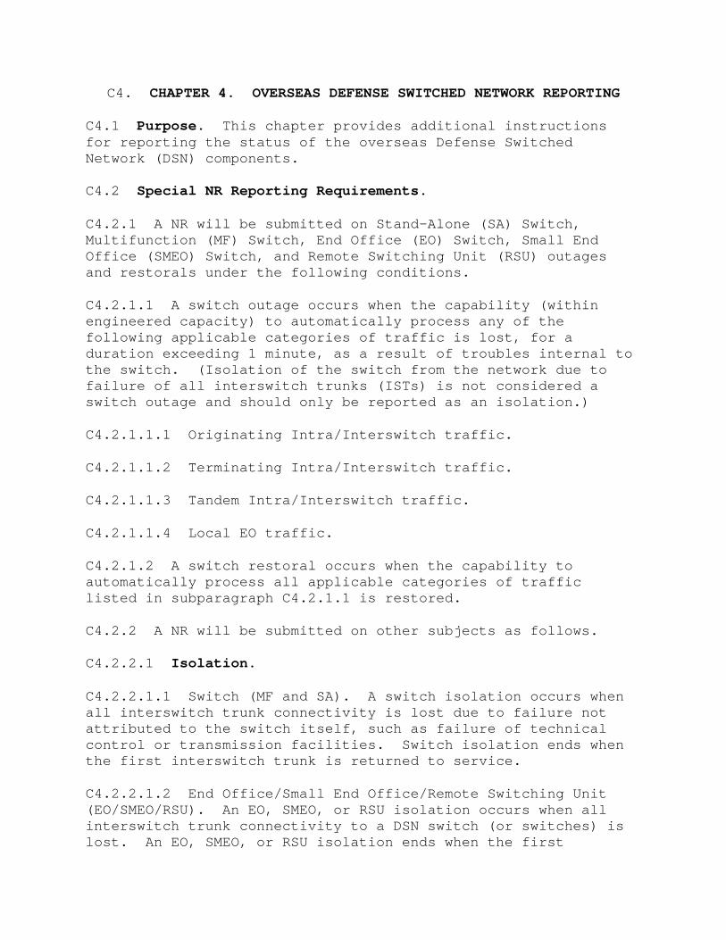
C4. CHAPTER 4. OVERSEAS DEFENSE SWITCHED NETWORK REPORTING
C4.1 Purpose. This chapter provides additional instructions for reporting the status of the overseas Defense Switched Network (DSN) components.
C4.2 Special NR Reporting Requirements.
C4.2.1 A NR will be submitted on Stand-Alone (SA) Switch, Multifunction (MF) Switch, End Office (EO) Switch, Small End Office (SMEO) Switch, and Remote Switching Unit (RSU) outages and restorals under the following conditions.
C4.2.1.1 A switch outage occurs when the capability (within engineered capacity) to automatically process any of the following applicable categories of traffic is lost, for a duration exceeding 1 minute, as a result of troubles internal to the switch. (Isolation of the switch from the network due to failure of all interswitch trunks (ISTs) is not considered a switch outage and should only be reported as an isolation.)
C4.2.1.1.1 Originating Intra/Interswitch traffic.
C4.2.1.1.2 Terminating Intra/Interswitch traffic.
C4.2.1.1.3 Tandem Intra/Interswitch traffic.
C4.2.1.1.4 Local EO traffic.
C4.2.1.2 A switch restoral occurs when the capability to automatically process all applicable categories of traffic listed in subparagraph C4.2.1.1 is restored.
C4.2.2 A NR will be submitted on other subjects as follows.
C4.2.2.1 Isolation.
C4.2.2.1.1 Switch (MF and SA). A switch isolation occurs when all interswitch trunk connectivity is lost due to failure not attributed to the switch itself, such as failure of technical control or transmission facilities. Switch isolation ends when the first interswitch trunk is returned to service.
C4.2.2.1.2 End Office/Small End Office/Remote Switching Unit (EO/SMEO/RSU). An EO, SMEO, or RSU isolation occurs when all interswitch trunk connectivity to a DSN switch (or switches) is lost. An EO, SMEO, or RSU isolation ends when the first

interswitch trunk to the EO, SMEO, or RSU is returned to service.
C4.2.2.1.3 Private Branch Exchange (PBX/EPX). A PBX/EPX isolation occurs when all access line connectivity to a DSN switch is lost. A PBX/EPX isolation ends when the first access line to the PBX/EPX is returned to service.
C4.2.2.2 Hazardous Conditions (HAZCONs). The following HAZCONs apply only when caused by actual failures. Switches are not placed in HAZCON by taking subsystems or equipment "off-line" for routine preventive maintenance as long as the subsystem or equipment can be immediately restored to service. Further, placing a switch in "manual" mode when performing routine maintenance does not place the switch in HAZCON.
C4.2.2.2.1 Failure of 25 percent of the following. (An amplifying report should be provided for all additional failures, or subsequent restorals, above the 25 percent HAZCON criteria.)
C4.2.2.2.1.1 Equipped dual-tone multifrequency (DTMF) transmitters, receivers, or transceivers.
C4.2.2.2.1.2 Equipped multifrequency (MF) transmitters, receivers, or transceivers.
C4.2.2.2.1.3 Equipped dial pulse (DP) transmitters, receivers, or transceivers.
C4.2.2.2.2 Failure of d.c. to a.c. inverter.
C4.2.2.2.3 Failure of two power rectifiers even though the remaining units are carrying the technical load. (The HAZCON ends upon restoral of one of the two failed rectifiers.)
C4.2.2.2.4 Failure of the primary or auxiliary a.c. power source. (If both fail, an amplifying report is required upon restoral of either.)
C4.2.2.2.5 Failure of environmental control facilities. (An amplifying report is required when a cabinet temperature of 90 degrees Fahrenheit (32 degrees Celsius) and/or relative humidity of 75 percent is reached. An amplifying report is required upon implementation of a subsystem "power down," or subsequent subsystem "power up." The "power down" report will identify specific subsystems deenergized.)
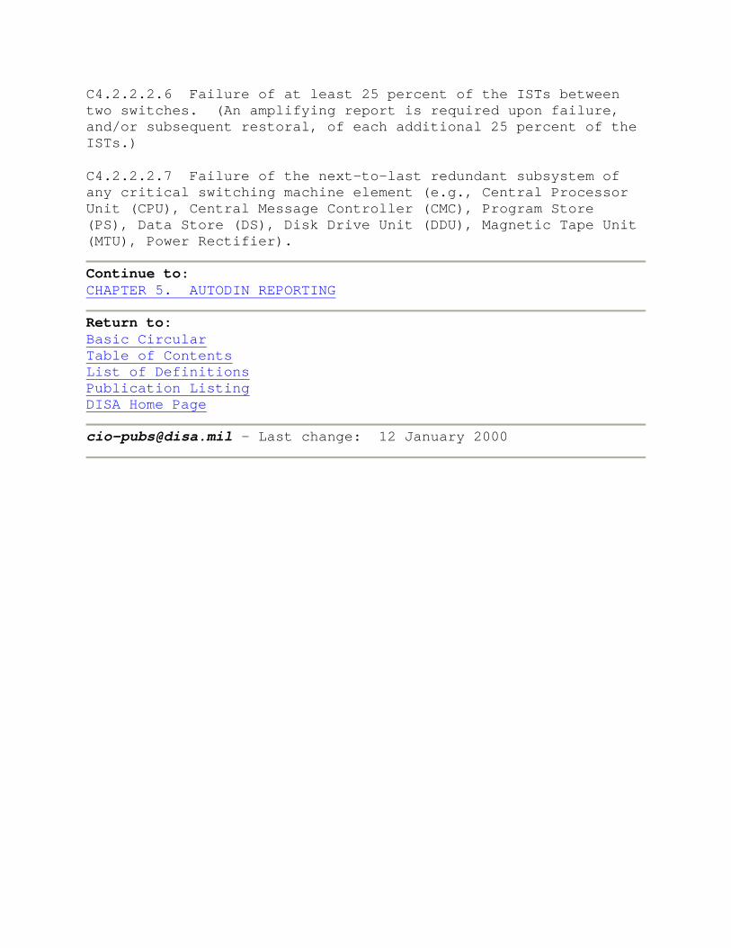
C4.2.2.2.6 Failure of at least 25 percent of the ISTs between two switches. (An amplifying report is required upon failure, and/or subsequent restoral, of each additional 25 percent of the ISTs.)
C4.2.2.2.7 Failure of the next-to-last redundant subsystem of any critical switching machine element (e.g., Central Processor Unit (CPU), Central Message Controller (CMC), Program Store (PS), Data Store (DS), Disk Drive Unit (DDU), Magnetic Tape Unit (MTU), Power Rectifier).
Continue to: CHAPTER 5. AUTODIN REPORTING
Return to: Basic Circular Table of Contents List of Definitions Publication Listing DISA Home Page
[email protected] - Last change: 12 January 2000

C5. CHAPTER 5. AUTODIN REPORTING
C5.1 Purpose. This chapter provides additional guidance for reporting AUTODIN status information.
C5.2 Special NR Reporting Requirements.
C5.2.1 Switch Outage and Restoral. An NR will be submitted as follows. (The traffic service section (TSS) should not be considered a subscriber channel restoral in the following cases.)
C5.2.1.1 When switching equipment is unable to process traffic due to environmental equipment failure, Autodin Switching Center (ASC) equipment malfunction or failure, software failure, or personnel error. The outage ends when the first interswitch trunk and the first subscriber channel are returned to service.
C5.2.1.2 At the time message switch system dry-up procedures (DRUP) are begun. The outage ends when the first interswitch trunk and first subscriber channel are placed in service.
C5.2.1.3 When a reload is performed. The outage ends when the first interswitch trunk and first subscriber channel are placed in service after the reload.
C5.2.1.4 When a message switch automatic or manual restart is begun which prohibits the switching equipment from processing traffic. The outage ends when service is restored after the restart. Restarts initiated for planned daily equipment reconfigurations (restart 00 or 01) will not be reported unless cycling time is lost during the restart. Restarts or any other ASC outages of less than 1 minute should not be reported.
C5.2.1.5 When all crypto facilities fail. The outage ends when the first interswitch trunk and the first secure subscriber channel are returned to service.
C5.2.2 Switch Isolation. A switch isolation occurs when all interswitch connectivity (every interswitch trunk) is lost. Switch isolation ends when the first interswitch trunk is returned to service.
C5.2.3 Traffic. Traffic in the ASC will be reported as specified in each DISA area's additional guidance to this Circular.

C5.3 Special FR Reporting Requirements. Reports should be submitted for items contained in chapter 1 of this Circular. Additional special instructions are as follows.
C5.3.1 Subscriber Access Line. Only the serving ASC will submit AUTODIN subscriber access line outage reports. ASCs will ensure that all reportable outages are coordinated with the subscriber and the assigned Communications Control Office (CCO).
C5.3.2 Part-Time Subscriber Outages. An outage that affects a part-time subscriber must be terminated at the scheduled closure time. If the failed condition is corrected while the subscriber is closed, no further report is required unless the RFO is different from that which was reported to close the outage. In that case, a correction report must be submitted in accordance with subparagraph C2.6.5.2.4. (This correction report may have to be submitted for the previous raday.) Should the failed condition still exist at the time of the scheduled opening, the circuit will be reported out at that time with the appropriate RFO code.
Continue to: CHAPTER 6. DEFENSE RED SWITCH NETWORK REPORTING
Return to: Basic Circular Table of Contents List of Definitions Publication Listing DISA Home Page
[email protected] - Last change: 12 January 2000

C6. CHAPTER 6. DEFENSE RED SWITCH NETWORK REPORTING
C6.1 Purpose. This chapter provides additional instructions for reporting the status of the Defense Red Switch Network (DRSN).
C6.2 Definitions. For reporting purposes, the following definitions apply for DRSN switches:
C6.2.1 A switch outage occurs when the capability to automatically process interswitch (originating or terminating) or tandem traffic is lost as a result of problems internal to the switch.
C6.2.2 A switch restoral occurs when the capability to process automatically all traffic listed in subparagraph C6.2.1 is restored.
C6.2.3 A switch isolation occurs when all interswitch trunk connectivity is lost due to failure not attributed to the switch itself, such as failure of technical control or transmission facilities. A switch isolation ends when the first interswitch trunk is returned to service.
C6.2.4 A HAZCON for a RED switch exists if any of the following or subparagraph C1.8 conditions are met. HAZCONs apply only when caused by actual failures of redundant subsystems. Switches must not be placed in HAZCON by taking subsystems or equipment "off-line" for routine preventive maintenance, as long as the redundant subsystem or equipment can be restored to service within a nominal time period.
C6.2.4.1 Failure of any power supply internal to the switch.
C6.2.4.2 Failure of the primary or auxiliary power source. If both fail, an amplifying report is required upon restoral of either.
C6.2.4.3 Failure of environmental control facilities.
C6.2.4.3.1 An amplifying report is required when a cabinet temperature of 90 degrees Fahrenheit (32 degrees Celsius) and/or relative humidity of 75 percent is reached.
C6.2.4.3.2 An amplifying report is required upon implementation of a subsystem "power down" or subsequent subsystem "power up."

The "power down" report will identify specific subsystems deenergized.
C6.2.4.4 Failure of the next-to-last redundant subsystem of any critical switching equipment element.
C6.2.4.5 Loss of processor redundancy caused by the failure of either the "A" or "B" processor.
C6.2.4.6 Loss of matrix redundancy caused by the failure of either the "A" or "B" matrix.
C6.3 Classified Information. Classified information should not be submitted in the reports required by this Circular.
Continue to: CHAPTER 7. RESERVED CHAPTER 8. DEFENSE SATELLITE COMMUNICATIONS SYSTEM REPORTING
Return to: Basic Circular Table of Contents List of Definitions Publication Listing DISA Home Page
[email protected] - Last change: 12 January 2000
C7. CHAPTER 7. [RESERVED]
Reserved for future DII reporting requirements.
Continue to: CHAPTER 8. DEFENSE SATELLITE COMMUNICATIONS SYSTEM REPORTING
Return to: Basic Circular Table of Contents List of Definitions Publication Listing DISA Home Page
[email protected] - Last change: 12 January 2000

C8. CHAPTER 8. DEFENSE SATELLITE COMMUNICATIONS SYSTEM REPORTING
C8.1 Purpose. This chapter provides additional instructions for reporting the status of the Defense Satellite Communications System (DSCS).
C8.2 Definitions.
C8.2.1 DSCS Earth Terminal Outage. Earth terminal facility outages are normally limited to outages of environmental or power equipment, or disasters (e.g., fires, floods, etc.), which render the earth terminal unusable. A facility outage should not be reported if connectivity to the satellite is lost, but there is still connectivity to the DII.
C8.2.2 DSCS Link Outage. Disruptions of the combined Radio Frequency (RF) signal path should be reported as link outages. For example, on a link without a power combiner, the link would extend from the output of the up-converter to the satellite. For a link with multiple up-converters, the output of the up-converter power combiner would start the link. A link should not be reported OUT if it loses its traffic due to a cause external to the link (e.g., a tandem link outage.)
C8.2.3 DSCS Trunk (Fourth Position Code "S") Outage. Disruptions of the aggregate digital data flow from earth terminal to earth terminal which are not caused by link outages, should be reported as "S" type trunk outages. The trunk starts at the output of the time division multiplex (TDM) equipment (input to the modulator), and ends at the distant earth terminal input to the TDM (output of the demodulator.)
C8.3 Special Reportable Conditions.
C8.3.1 Single-Trunk Link Reporting. In cases where only a single "S" type trunk rides a link (only one up- or down-converter), the above definitions still apply. That is, failure of the modem, bulk encryption device, or up/down-converter are trunk outages; whereas failure of the Interfacility Link Amplifier (IFLA), Intermediate Power Amplifier (IPA), Power Amplifier (PA), antenna, or parametric amplifier (PARAMP) are link outages.
C8.3.2 HAZCON.

C8.3.2.1 Link HAZCONs should be reported when there is a lack of spare components, to include modems, KY-801 coders, up/down converters, cesium standard or stable timing source, and DCSS (case IV) fiber optic ICF trunks. DISA policy requires a minimum of one spare of each of these components per terminal.
C8.3.2.2 A link HAZCON should be reported due to the failure of two power amplifiers in AN/GSC-52 terminals, or one power amplifier in all other terminals.
C8.3.2.3 Satellite facilities with links comprised of multiple trunks should not declare the link in HAZCON based solely on the loss of redundant trunk equipment. Restoration priorities exist to preempt equipment on lower mission priority trunks in order to maintain service to higher priority trunks. A HAZCON exists when the failure of a trunk would result in a link outage, and lack of available redundant equipment should the on-line trunk equipment fail.
C8.4 Special NR Reporting Requirements. All nonformatted reports on outages and HAZCONs should be submitted to the DSCS operations center which controls the accessed satellite, via their respective Smart Multi-Circuit Terminal/Terrestrial Critical Control Circuit (SMCT/TCCC). DSN contact is authorized only in the event of a SMCT/TCCC failure.
C8.5 Special FR Reporting Requirements. All formatted reports should be submitted to the appropriate DISA area, which is determined by the geographical location of the earth terminal.
Continue to: CHAPTER 9. TECHNICAL DETAILS
Return to: Basic Circular Table of Contents List of Definitions Publication Listing DISA Home Page
[email protected] - Last change: 12 January 2000

C9. CHAPTER 9. TECHNICAL DETAILS
C9.1 Purpose. The intent of this chapter is to provide additional information on the details of formatted reporting and the processing of the reports by DISA.
C9.2 Line Format. Every information line must conform to one of the following formats. Items in parentheses should be entered by the reporter. Items in brackets are optional, depending on the type of report. No spaces, blanks, carriage returns, or line feeds are allowed within or between data elements, except in the TEXT portion of the remarks.
C9.2.1 The first line of the report must consist only of four opening parentheses: ((((.
C9.2.2 The second line of the report has the following format:
S(RFD)/(SN)/(CDT)[/OUT(Z)][/IN(Z)][/(RFO)][/RMKS(TEXT)XXXX]
C9.2.2.1 RFD: Reporting facility designator (3 characters).
C9.2.2.2 SN: Sequence number (3 numbers maximum).
C9.2.2.3 CDT: Report cutoff date-time (6 characters).
C9.2.2.4 Other items are optional, as stated below.
C9.2.3 All lines except the first, second, and last use the following structure:
(ID)(SUBJ)[HAZ][/(SA)][/OUT(Z)][/IN(Z)][/(RFO)][/RMKS(TEXT)XXXX]
C9.2.3.1 ID: One of four information line symbols ("S", "L", "K", or "U") is required to identify the type of subject.
C9.2.3.2 SUBJ: A subject is required as follows:
C9.2.3.2.1 S-line: Reporting designator (3 characters).
C9.2.3.2.2 L-line: Link ID (5 characters).
C9.2.3.2.3 K-line: Trunk ID (6 characters).
C9.2.3.2.4 U-line: Circuit number (4 characters) or CCSD (8 characters).

C9.2.3.3 HAZ: Used (only) with RMKS on S- and L-lines to report HAZCON information.
C9.2.3.4 SA: Used to report a circuit's service availability (SA) on U-lines, when required (1 character).
C9.2.3.5 OUT: Time outage began identifier.
C9.2.3.6 Z: Universal (Zulu) time (4 characters).
C9.2.3.7 IN: Time outage ended identifier.
C9.2.3.8 RFO: Used (only) with OUT and/or IN to state the reason for the outage (4 characters).
C9.2.3.9 RMKS: Can be used on any information line to report narrative remarks. TEXT can be any length, as long as each line does not exceed 69 characters. Remarks must end with four Xs (XXXX), all on the same line.
C9.2.4 The last line of the report must consist only of four closing parentheses: )))).
C9.3 Error Checking. Formatted reports are processed automatically by a computer at each DISA area center. Every line of the report undergoes a number of format and content checks.
C9.3.1 Message Processor (Automated). The message processor program is responsible for receiving and filing the reports. However, numerous verification tests must be performed to ensure the data is valid and formatted as stated in chapter 2, before it can be filed. Errors detected are sent to an error file, which must be manually cleared. The following states some of these tests.
C9.3.1.1 Reporting designators are checked to ensure they are valid codes.
C9.3.1.2 The report serial number is checked to ensure the report is not a duplicate.
C9.3.1.3 For L- and K-lines, the subject is checked to ensure it terminates at the reporting designator identified in the last preceding S-line. The computer then uses that reporting designator as the receive facility, to determine which direction is being reported.

C9.3.1.4 When only the last four (circuit number) of a CCSD is reported on a U-line, the computer searches the database for the full CCSD of the reported circuit number, with a service availability (SA) of "A". Similarly, if an SA is reported, the computer will find and use the full CCSD for that SA in subsequent processing.
C9.3.1.5 RFO codes and required remarks are validated for conditions stated in chapter 3.
C9.3.1.6 If both OUT and IN times are reported, the IN time must be greater than the OUT time.
C9.3.2 End of Raday (Semi-Automated). Several queries are available to assist in the review of reports for a whole raday. The following checks can be performed:
C9.3.2.1 Reporting stations without a filed 2400Z report.
C9.3.2.2 Missing report sequence (serial) numbers. This report is used to check that all reports submitted by a facility are received.
C9.3.2.3 Verification of carryover outages. That is, an item which was OUT at 2400Z one day is logged out the next day at 0000Z.
C9.3.2.4 Identification of IN times without preceding OUT times.
C9.3.2.5 Manual check to ensure all RMKS end with "XXXX". If they do not (for example, only "XXX"), all subsequent lines until "XXXX," or the end of the report, will be considered as remarks for that report.
C9.3.3 End-of-Day Processing (Automated). After all 2400Z reports have been received, two programs are run to process the reported data.
C9.3.3.1 The preliminary overlap program is responsible for making time and RFO corrections, matching OUT and IN times (and keeping the IN RFO) if they are reported on separate lines, and closing any open outages at 2400Z. This program looks at reports from only one reporting designator at a time, to preclude reports from one facility interacting with reports from another facility on the same subject. Two error conditions are identified by this program:

C9.3.3.1.1 An IN time without a preceding OUT time. (The program sends the record to an error report.)
C9.3.3.1.2 Two or more OUT times are reported before an IN. (The program sends the condition to the error report, but then processes the outages. The time from the first to second OUT reports is logged with a first position code "Y" (decoded as "reporting error"), and a location code of the reporting facility.)
C9.3.3.2 The second program perform the lower-level generation and final overlap processes.
C9.3.3.2.1 The lower-level generation program creates outages for links and trunks based on reported higher-level outages.
C9.3.3.2.2 The overlap program then combines all the reports on a subject, and selects only one for each minute of the day. For example, if a link is logged OUT, and then one of the terminal facilities fails and is restored before the link is returned to service, the link outage record will show the link outage interrupted by the (lower-level generated) facility outage. (Without the preliminary overlap program the facility restoral would have terminated the link outage and the reporting facility would have had to report the link OUT again.)
C9.3.3.3 The processed reports are placed in a historical file. This file can be queried on-line and is used to produce the monthly management products.
Return to: Top of Chapter 9 Basic Circular Table of Contents List of Definitions Publication Listing DISA Home Page
[email protected] - Last change: 12 January 2000