![Webasto Manual 5000778A[1]](https://static.fdocuments.in/doc/165x107/5521053d4a795976718b4a19/webasto-manual-5000778a1.jpg)
Defender Puma 110 Fuel Tank Removal and Webasto fuel pick ... Puma 110... · Defender Puma 110 Fuel...
8
Defender Puma 110 Fuel Tank Removal and Webasto fuel pick-up pipe installation These notes describe steps in removing the fuel tank on the Puma to install a Webasto fuel pick up pipe and fuel dosing pump. They are based purely on my experience and are not intended as definitive instructions – usual caveats about no liability apply. Details may vary with different models, this was a UK spec 2007 Defender Puma 110 XS County Station Wagon. General Notes: Not having a ramp, I performed this job with the Land Rover on all four wheels and part of the tow bar (the side arms) removed. If I were doing it again I would remove the two rear wheels and place the rear on axle stands, remove the whole of the tow bar and remove the mud flap on the nearside rear (UK passenger side). This would add approximately 30 mins to the job but save a great deal of frustration in providing better access. Run the tank down as far as possible before starting the job then siphon off all remaining fuel – this just makes handling the tank easier, even a couple of gallons can make it quite heavy. Finally before starting, get the insides of the wheel arches and general area of working as clean as possible to minimise dirt getting into the fuel. Process steps: 1. Remove rear road wheels 2. Undo 12n electric socket and remove tow bar 3. Remove nearside mudflap 4. Remove eight nuts/bolts securing bushes for rear anti-roll bar (you don’t need to remove roll bar completely just swing it down out of the way) 5. Remove the lower hose clip on the main filler pipe (offside rear wheel arch) and loosen pipe
Transcript of Defender Puma 110 Fuel Tank Removal and Webasto fuel pick ... Puma 110... · Defender Puma 110 Fuel...

Defender Puma 110 Fuel Tank Removal and Webasto fuel pick-up pipe installation
These notes describe steps in removing the fuel tank on the Puma to install a Webasto fuel pick up
pipe and fuel dosing pump. They are based purely on my experience and are not intended as
definitive instructions – usual caveats about no liability apply. Details may vary with different
models, this was a UK spec 2007 Defender Puma 110 XS County Station Wagon.
General Notes:
Not having a ramp, I performed this job with the Land Rover on all four wheels and part of the tow
bar (the side arms) removed. If I were doing it again I would remove the two rear wheels and place
the rear on axle stands, remove the whole of the tow bar and remove the mud flap on the nearside
rear (UK passenger side). This would add approximately 30 mins to the job but save a great deal of
frustration in providing better access. Run the tank down as far as possible before starting the job
then siphon off all remaining fuel – this just makes handling the tank easier, even a couple of gallons
can make it quite heavy. Finally before starting, get the insides of the wheel arches and general
area of working as clean as possible to minimise dirt getting into the fuel.
Process steps:
1. Remove rear road wheels
2. Undo 12n electric socket and remove tow bar
3. Remove nearside mudflap
4. Remove eight nuts/bolts securing bushes for rear anti-roll bar (you don’t need to remove roll
bar completely just swing it down out of the way)
5. Remove the lower hose clip on the main filler pipe (offside rear wheel arch) and loosen pipe
6. Remove the upper hose clip on the fuel overflow/breather pipe (offside rear wheel arch) and
separate pipe from filler cap fitting. Stuff a clean rag down the end to prevent dirt ingress.
7. Loosen the two 10mm bolts to release the fuel tank hold down strap (offside rear wheel
arch) You don’t need to take this strap off altogether, just release the tension. You can see
the two nuts in the bottom left hand corner of the pic in Step 5 above.
8. Free the fuel tank breather pipe (nearside rear wheel arch). This should be behind the
plastic cover inside the wheel arch (there was a LR mod to move it out of the way of road
dirt/water however also see pic in Step 27 for alternative location). The pipe is secured by
two plastic clips, one right at the rear of the chassis (facing rearwards) and one on the inside
of the chassis. This is why removing the wheel and mudflap provides better access.
9. Remove the two nuts holding the tank supporting pan at the rear. These are located in the
two large holes in the rear of the chassis cross member.

10. With a jack supporting the tank/metal supporting pan undo and remove the two bolts at the
front of the pan .
11. Gently start lowering the tank but at an angle so the rear of the tank lowers first. This is to
give access to the fuel pipes and wiring for the fuel gauge. This is why removing the
complete tow bar is a good idea as otherwise access is very awkward.
12. As the tank starts to be lowered remove the main filler pipe (clip undone at Step 5) and
cover the end with a clean rag/cloth to prevent dirt ingress.
13. Remove the two fuel pipes noting which is which for when you put them back. To release
them press both sides of the red or yellow clips as appropriate. Make sure there is no strain
on the pipes or they won’t release.
14. Remove the wiring connector for the fuel gauge.
15. Remove tank completely (check the fuel breather pipe (nearside) is completely free and also
pull the fuel overflow/breather pipe (offside) through the gap between the chassis/body.
16. Ensure fuel pipe stubs are covered then wash/dry tank thoroughly paying particular
attention to the areas around the fuel sender unit.
17. Have a cup of tea!

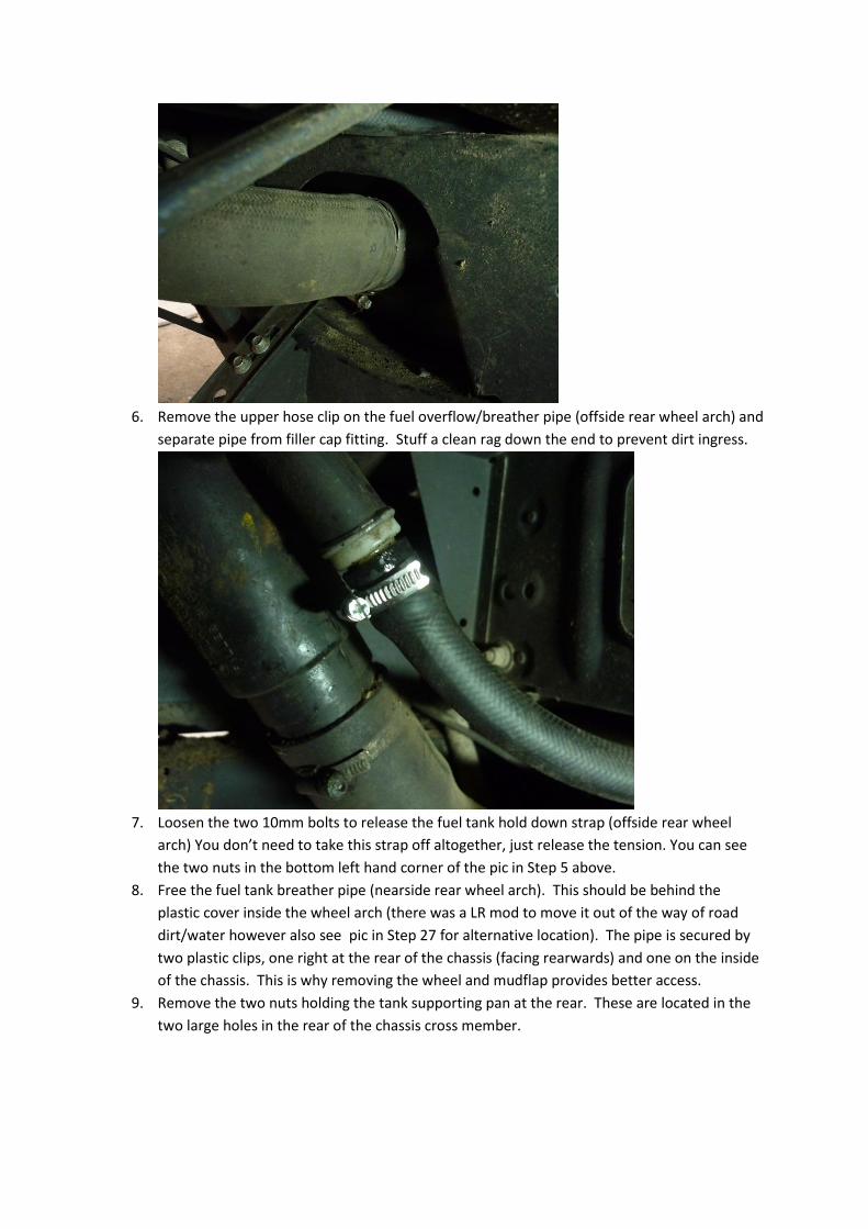
18. The fuel sender is removed by unscrewing the metal ring on top of the unit. It’s quite tight
and whilst you may have some success nudging it round with a screwdriver it’s better with a
proper tool. Land Rover make a special tool, part number 310-118
but it’s quite easy to fabricate one from some lengths of steel bar welded together with a
nut on top – as per the pic below. As you can see it doesn’t need to be fancy, just functional.
Having a proper tool also allows you to torque the ring correctly (35Nm) when replacing it.
19. Having removed the metal ring the sender unit pulls straight out. Do this carefully as the
plastic tank at the bottom of the sender will need to drain any residual fuel and be careful
not to bend the float for the fuel gauge.
20. With the sender unit out and on the bench drill an 8.5mm hole for the Webasto fuel pick up.
I used a low profile model, (Webasto part number 41S45017A). If you use a different part no
then check the hole size yourself. Be careful where you drill the hole as there’s limited room
for the fuel pick up nut due to the various plastic bracing lugs on the sender unit.
21. Install the Webasto pick up (you may need to gently bend it to fit) then compress the sender
unit until the spring is fully compressed. Mark a point on the Webasto fuel pick up pipe
which is about 10-15 mm above the bottom of the tank when the unit is fully compressed.
See pic below.

22. Remove pickup pipe and cut to length. Ensure pipe is not blocked (through sawing it off)
and no rough edges.
23. Re-install pickup pipe and connect Webasto fuel pipe via Webasto rubber connector. Pay
particular attention to using the correct clips and ensuring the line is airtight.
24. Refit the whole sender unit into the tank – you’ll need to compress it slightly to get it in.
25. Replace the metal ring and torque down to 35Nm
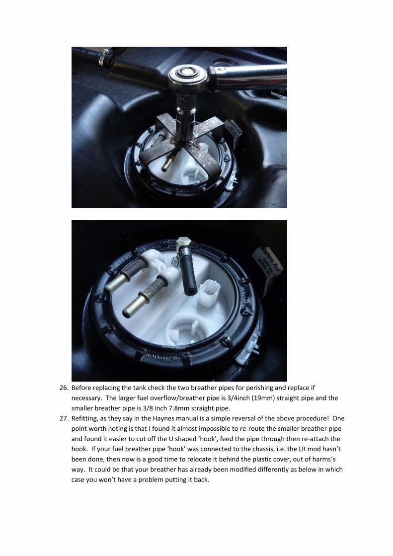
26. Before replacing the tank check the two breather pipes for perishing and replace if
necessary. The larger fuel overflow/breather pipe is 3/4inch (19mm) straight pipe and the
smaller breather pipe is 3/8 inch 7.8mm straight pipe.
27. Refitting, as they say in the Haynes manual is a simple reversal of the above procedure! One
point worth noting is that I found it almost impossible to re-route the smaller breather pipe
and found it easier to cut off the U shaped ‘hook’, feed the pipe through then re-attach the
hook. If your fuel breather pipe ‘hook’ was connected to the chassis, i.e. the LR mod hasn’t
been done, then now is a good time to relocate it behind the plastic cover, out of harms’s
way. It could be that your breather has already been modified differently as below in which
case you won’t have a problem putting it back.

Also don’t forget to re-tension the metal band that goes over the top of the tank. You can
do this with a screwdriver or metal rod whilst doing the nuts up. You can see the band in the
picture above and the two tensioning nuts bottom right hand corner.
When refitting the main fuel pipes make sure they’re fully clipped home – you don’t need to
depress the yellow or red clips but the connectors do need to ‘click’ in place.
28. I fitted the Webasto dosing pump on the inside of the offside chassis rail, on the wheel arch.
It was much more awkward than fitting it on the wheel side but hopefully should be more
protected from dirt thrown up by the wheels. The yellow in the picture is some temporary
tape to protect the electrical connection until I get time to fit the wiring loom.
To fit the pump I drilled a 9mm hole in the chassis and inserted a 6mm rivnut using a
Memfast tool. You can achieve the same using a 6mm bolt, nut and washer as a rivnut tool

but if you’re unsure about rivnets in general then have a look on the forums, there’s plenty
of advice/instructions there.
29. The Webasto fuel pipe is routed following the existing fuel pipe route. The pipe can be
clipped in place using the existing fuel pipe clips right up into the engine bay.
30. Start planning the rest of the Webasto install!