Defect Analysis and Data Collection Software for an Iron ...
64
Defect Analysis and Data Collection Software for an Iron Foundry A Manuscript Submitted to the Department of Computer Science and the Faculty of the University of Wisconsin-La Crosse La Crosse, Wisconsin by Brad Zebell in Partial Fulfillment of the Requirements for the Degree of Master of Software Engineering May, 2009
Transcript of Defect Analysis and Data Collection Software for an Iron ...
Defect Analysis and Data Collection Software for an
Iron Foundry
A Manuscript
Submitted to
the Department of Computer Science
and the Faculty of the
University of Wisconsin-La Crosse
La Crosse, Wisconsin
by
Brad Zebell
in Partial Fulfillment of the
Requirements for the Degree of
Master of Software Engineering
May, 2009

Defect Analysis and Data Collection Software for an Iron Foundry
By Brad Zebell
We recommend acceptance of this manuscript in partial fulfillment of this candidate‟s requirements for the degree of Master of Software Engineering in Computer Science. The
candidate has completed the oral examination requirement of the capstone project for the degree.
____________________________________ _______________________ Dr. Kasi Periyasamy Date Examination Committee Chairperson
____________________________________ _______________________ Dr, David Riley Date Examination Committee Member
____________________________________ _______________________ Dr. Mao Zheng Date Examination Committee Member

- iii -
ABSTRACT
Zebell, Brad, M., “Defect Analysis and Data Collection Software for an Iron
Foundry”, Master of Software Engineering, May 2009, Dr. Kasi Periyasamy, Dr.
David Riley.
Torrance Casting is an iron foundry located in La Crosse, Wisconsin. The
foundry produces castings by melting raw materials into molten iron, which are then
poured into molds created from compressed sand. While creating castings from
molten iron is a considerably low tech endeavor, there are many opportunities to
improve the efficiency of their business through computer software. The process of
creating castings produces a large array of data that must be recorded for accounting,
defect analysis and process control. Currently this data is recorded manually on paper
forms and filed away for future reference.
This manuscript describes the design and development of a software
application for an iron foundry in process control, data collection, and defect
identification. The application allows the foundry workers to replace current paper
processes with a flexible interactive process to record data produced in the casting
process. It also replaces manual data collection with intuitive graphical data entry
screens. This data can later be easily analyzed to determine the cause of casting
defects.

- iv -
ACKNOWLEDGEMENTS
I would like to express my sincere thanks to my project advisors Dr. Kasi Periyasamy
and Dr. David Riley for their valuable guidance. I‟d like to thank the project sponsor,
Torrance Casting, and specifically John Torrance for his time, patience, and vision in
the development of this software application. In addition I‟d like to thank my wife
Sadie for her patience and constant encouragement throughout the project.

- v -
TABLE OF CONTENTS
Page
ABSTRACT............................................................................................................iii
ACKNOWLEDGEMENTS....................................................................................iv
TABLE OF CONTENTS.........................................................................................v
LIST OF TABLES..................................................................................................vi
LIST OF FIGURES...............................................................................................vii
GLOSSARY.........................................................................................................viii
1. Introduction ........................................................................................................1
2. The Lean Foundry Application Suite...................................................................4
3. Requirements........................................................................................................7
3.1. Furnace Charge Software and GUI Requirements........................................7
3.2. Inoculation Software and GUI Requirements...............................................8
3.3. CastingPour Software and GUI Requirements............................................12
3.4. Administration Software and GUI Requirements........................................13
3.5. Mold Interface Software and GUI Requirements........................................17
3.6. Defect Analyzer Software and GUI Requirements......................................19
3.7. GUI Requirements for Keyboard less controls............................................20
3.8. Lean Foundry User Classifications (Use Case Models)..............................21
4. Design and Implementation Challenges..............................................................26
4.1. Scope Creep................................................................................................26
4.2. Schedules of Prototypes...............................................................................27
4.3. Database Architecture .................................................................................27
5. Detailed Design....................................................................................................29
5.1. Furnace Charge and Mold Interface Design................................................29
5.2 Inoculation, Casting Pour, Administrator, and Defect Analyzer Design......31

- vi -
5.3 Database Design............................................................................................36
6. Coding and Implementation.................................................................................38
7. Limitations............................................................................................................40
8 Continuing Work...................................................................................................44
9. Conclusion............................................................................................................43
10. Bibliography.......................................................................................................44
Appendix A: Lean Foundry Table Layout Listing...................................................45

- vii -
LIST OF FIGURES
Figure Page
1. Furnace Charge GUI.............................................................................................8
2. Inoculation GUI..................................................................... .............................10
3. Inoculation Select Heat GUI...............................................................................11
4. Inoculation Select Mold GUI .............................................................................12
5. CastingPour GUI............................................................... .................................13
6. Administration Furnace Charge Screen GUI......................................................15
7. Administration Inoculation Screen GUI.............................................................16
8. Administration Employee Screen GUI...............................................................17
9. Mold Interface GUI............................................................................................19
10. Defect Analyzer GUI........................................................................................20
11. Increment and decrement GUI control..............................................................21
12. Number Chooser GUI control...........................................................................21
13. Furnace Charge and Administration Furnace Charge Screen Use Case...........22
14. Inoculation and Administration Inoculation Screen Use Case..........................23
15. Casting Pour Use Case......................................................................................24
16. Defect Analyzer Use Case.................................................................................25
17. UML Class Diagram for Furnace Charge application.......................................30
18. UML Class Diagram for Mold Interface application.........................................31
19. UML Class Diagram for Inoculation application...............................................33
20. UML Class Diagram for CastingPour application.............................................34
21. UML Class Diagram for Administrator application..........................................35
22. UML Class Diagram for Defect Analyzer application......................................36
23. Simplified Database Diagram For Lean Foundry Tables..................................37

- viii -
GLOSSARY
Casting
The metal shape obtained as a result of pouring liquid metal into a mold.
Charge
A given weight of metal introduced into a furnace.
Chill
Metal, graphite or carbon blocks that are added to the molten metal to increase the
rate of heat removal during solidification and reduce shrinkage defects.
Ductile Iron
An iron/graphite composite in which the graphite exists in spheres or nodules,
allowing the material to deform rather than fracture when placed under mechanical
stress.
Gray Iron
Iron in which a large percentage of carbon content is in the form of graphite flakes.
The graphite flakes cause it to have low shock resistance, but high damping ability.
Traditionally referred to as “Cast Iron”, gray iron is widely used for engine
components in automobiles and trucks.
Heat
The process of heating, melting, and subsequent removing of a single furnace charge
of metal.

- ix -
Inoculant
Materials, which when added to molten metal, modify the structure and thereby
change the physical and mechanical properties.
Inoculation
A process of adding inoculants to molten metal in the ladle for the purpose of
controlling the structure to an extent not possible by control of chemical analysis and
other normal variables.
Ladle
Metal receptacle frequently lined with refractories used for transporting and pouring
molten metal.
Mold
Normally consists of a top and bottom form, made of sand, metal, or any other
investment material which contains the cavity into which molten metal is poured to
produce a casting of definite shape and outline.
Mold Line
Line of tracks on which molds are conveyed from a molding station to a pouring
station to shakeout.
Ni-Hard Iron
Cast iron in which most of the carbon is present in the form of iron carbide,
containing 4% Nickel and 2% Chromium.
Pourer
Person responsible for filling molds with the molten metal from a ladle.

- x -
Slag
The nonmetallic covering on molten metal resulting from the combination of
impurities in the initial charge like ash from fuel, and any silica and clay eroded from
the refactory lining.
Slagging
The process of skimming material off prior to pouring the metal.
Tap
The withdrawal of a molten charge from a furnace. One heat creates multiple taps.
Test Bar
Standard specimen bar designed to permit determination of mechanical properties of
the metal from which it was poured.

- 1 -
1. Introduction
Torrance Casting has been operating an iron foundry in La Crosse since 1876.
The principal product at that time was creating stoves, along with iron and brass
castings for buildings, bridges and machinery. In the 1920‟s, production changed to
creating industrial castings for manufacturing firms. At this time, the demand for
municipal and construction castings increased as well. Ten years later, castings for
heating and air conditioning industries became the principal product of Torrance
Casting. Today, the company continues to produce castings throughout the industry
in such applications as compressors, pumps, hydraulic valves, abrasion resistant
applications, agricultural equipment, conveyor equipment, railroad products and
many other uses.
Over the time, much progress has been made in the use of equipment,
facilities, and processes at Torrance. However, in a few aspects of the business, the
use of computers has been slow or nonexistent. A visit to the foundry reveals a
business largely driven by paper and clipboards hung throughout the foundry floor.
This project aims to replace and automate some of these paper driven processes.
The first and foremost step towards efficient operations of the foundry was to
set up a server with a database for data collection, thus replacing several paper forms
currently used throughout the foundry. Along with this database, several graphical
software applications were setup throughout the casting process to allow users to
record data they would normally collect on paper forms. These applications also
allow the user to instantly lookup up the correct ratios of raw materials for over 30
different types of iron Torrance Casting pours.
The collection of this data in a structured database allows Torrance to easily
analyze all the collected data. Besides improving the speed of the casting process, the

- 2 -
database can also help improve the quality of castings created. It is now possible to
review all relevant data for a defective casting. This knowledge could possibly be
used to prevent future occurrences of similar defects.
Three processes were selected for automation. The first process was to
automate the charging of the furnace. The software assists a user in creating the
correct type of iron and collected data related to the melting of the charge materials.
The second process automated was the inoculation process, allowing the user plan the
correct amount of molten iron required to pour the required castings, and also store
any data produced during this process. The third and final automated process was the
storing of data related to the pouring of molten iron into the casting molds. The
process of planning which castings to pour throughout the days was considered at one
point of the project but ultimately was scrapped due to complexity and time
constraints.
The project has been implemented in several phases. The first phase included
the setup and installation of a database and table structures to store the foundry data,
installation of the Furnace Charge, Administration, and Mold Interface applications.
The second phase included the installation of the Inoculation, Casting Pour, and
Defect Analyzer applications. All applications have been created, but due to time
constraints, only the first phase has been installed at Torrance Casting. The first
phase itself has been considered an overwhelming success by the project sponsor
because it saves a lot of time by the workers and greatly improves the operating
efficiency of the foundry.
The structure of the rest of this document is as follows. Chapter 2 briefly
discusses the casting process, current Torrance data collection methods and the
processes selected for automated data collection. Chapter 3 discusses the software
requirements gathered throughout the project. Chapter 4 discusses the challenges the
project encountered during design and implementation phases. A detailed design of
the Lean Foundry application is described in Chapter 5, followed by the work
involved in the coding and implementation of the Lean Foundry application given in

- 3 -
Chapter 6. Chapters 7 and 8 respectively discuss the limitations of the application
and continuing work that remains.

- 4 -
2. The Lean Foundry Application Suite
A defective casting can usually be attributed to the same factors: incorrect
ratio of ingredients, slow pouring time, and incorrect temperature at time of pour, etc.
The historical reoccurrence of these factors shows the need for a system to accurately
gather and store all relevant data required to identify the cause of defects and possibly
prevent future occurrences.
A simplistic view of the casting process reveals that there are three distinct
areas where a defect may occur during casting. These are Furnace Charge,
Inoculation, and Casting. Each of these points offers a wealth of data to be collected
for analysis at a later time in the event of a defect. Previously, this data was collected
on paper forms or not collected at all. When a customer notifies Torrance Casting of
a defect, a manual process of reviewing all relevant paperwork begins. Based upon
the data reported in the paperwork, the cause of the defect is determined. The paper-
based process is not only time consuming but may lead to several inconsistencies. For
example, if the person entering the data at a particular point does not include all
necessary information for analysis, it is not possible to use the data for analysis.
Further, this data is expected to be consistent with the data collected from other
points. Otherwise, the result of analysis may lead to an inconsistent conclusion. It is
therefore evident that a computerized data collection process is necessary to improve
the speed as well as to check the consistency and completion of the data collected.
The data collection software created for Torrance Casting attempts to collect
data at the same three points mentioned earlier allowing for a fast, accurate, and
complete view of all data relevant to the casting of a specific part. Iron casting is a
very time sensitive process, and so the data collection must be accomplished without

- 5 -
slowing the process. In fact, increasing the speed of data collection over current
manual methods is a goal of this project as well.
The first point of data collection is called the Furnace Charge, during which
raw materials are melted in a furnace. Torrance Casting creates castings from three
main iron types, Ductile, Grey, and Ni-Hard, each having several variations. The
raw materials required for each main type are determined by ratio of weights. Each
iron type requires the operator to place the appropriate amount of material in the
furnace. A normal heat has about a 4000 pound target which includes all the
materials. The size and weight of raw materials being weighed for the furnace make
it difficult to achieve the exact weight required for the specific iron type, and
therefore the user must have the ability to adjust the weight of each material, which in
turn changes the ratios of other materials.
The Furnace Charge software collects the following data at the data points.
Weight of every raw material placed in furnace.
Temperature of each tap.
Pounds of carbon reading for each tap.
Active carbon equivalent reading for each tap.
Employee operating furnace.
The second point of data collection is the „Inoculation process‟. In this
process, each furnace tap is split into two pouring ladles, in which very small amounts
of inoculants are added to the molten iron to create the desired iron type. The amount
of inoculation required is determined by the iron type and the weight of iron in the
ladle. The operator will use the software to predetermine the casting and the number
of each casting he plans to pour. This allows the software to calculate the amount of
iron needed in the ladle and the amounts of each inoculant to add to the ladle.

- 6 -
The Inoculation software collects the following data in this data point.
Inoculation weights.
Company and part id to pour.
Number of castings to pour.
Mold line to pour the castings on.
Estimated amount of iron spilled or wasted.
Employee pouring casting.
The third and final point of data collection is the „Casting process‟. At this
point, the inoculated molten iron is poured from a ladle into a sand mold where it will
cool and harden into the desired part.
The Casting software collects the following data during the casting process.
Number of castings actually poured.
Temperature of iron at the beginning of pouring.
Temperature of iron at the middle of pouring.
Temperature of iron at the end of pouring.

- 7 -
3. Requirements
This chapter explains the core requirements of each of the Lean Foundry
application suites pieces. A prototyping process was used as the software
development model throughout the project, because all the requirements were not
identified at the onset of the project. Many of the requirements were created,
removed and modified throughout the development of the project. This chapter
includes the requirements at completion of the project.
3.1 Furnace Charge Software and GUI Requirements
The following list summarizes the most important requirements of the Furnace
Charge software.
Allow user to create new charge heat.
Allow user to navigate between previously created heats.
Allow user to increase or decrease weights of charge materials by using
simple mouse clicks.
Allow user to record up to four temperatures per heat.
Allow user to record up to four active carbon equivalent values per heat.
Allow user to record up to four pounds of carbon values per heat.
Allow user to record, furnace, shift, employee operating furnace, and
number of times a furnace is slagged.
Allow user to select the type of Iron to make and pre-fill charge material
weights and disable non-relevant charge materials.

- 8 -
Notify user if the value of a charge material is not in normally accepted
range.
Figure 1 shows the graphical user interface for the Furnace Charge application.
Figure 1. Furnace Charge GUI
3.2 Inoculation Software and GUI Requirements
The following list summarizes the most important requirements of the
Inoculation application.
Allow user to select number of molds to pour.
Allow user to record the actual weight of the iron in the ladle.

- 9 -
Allow user to record amount of chill added to the ladle, updating iron
required in ladle.
Allow user to modify weight of iron required to fill a mold.
Allow user to select iron inoculant, calculating weights of inoculants to
add to ladle.
Allow user to record the predicted amount of spillage updating iron
required in ladle.
Allow user to record test bars to pour updating iron required in ladle.
Allow user to create new furnace tap.
If only one heat exists with iron left to pour, automatically create the tap
from this heat.
If more than one heat exists with iron left to pour, allow the user to select
the appropriate heat to create the tap.
Allow user to select the molds to pour from either recently poured molds
or all molds available in the database.
Allow user to update the amount of iron required to fill a mold.
Allow user to filter the available molds by any combination of customer,
part, iron or mold weight.

- 10 -
Figure 2 shows the graphical user interface for the Inoculation application.
Figure 2. Inoculation GUI

- 11 -
Figure 3 shows the graphical user interface for Heat Selection in the Inoculation
application.
Figure 3. GUI for selection of Heat for Inoculation

- 12 -
Figure 4 shows the graphical user interface for selecting a mold in the Inoculation
application.
Figure 4. GUI for selection of Mold for Inoculation
3.3 CastingPour Software and GUI Requirements
The following list summarizes the most important requirements of the
CastingPour application.
Allow user to record how many molds were actually poured.
Allow user to record temperature at the beginning of ladle pour.
Allow user to record temperature at the middle of ladle pour.
Allow user to record temperature at the end of ladle pour.
Figure 5 shows the graphical user interface for the CastingPour application.

- 13 -
Figure 5. CastingPour GUI
3.4 Administration Software and GUI Requirements
The Administration Software allows a user to easily modify and control the
Furnace Charge, Inoculation and Casting pieces of software. It allows the user to
create different types of irons, Inoculant types, and set values for various parameters.
The following list summarizes the most important requirements of the Administration
application furnace charge screen.
Allow user to create new Iron type.
Allow user to select whether or not the Iron type is visible to the Furnace
Charge software.
Allow user to create new version of existing iron type preserving original
versions.

- 14 -
Allow user to store the target pounds of carbon value.
Allow user to store the target active carbon equivalent value.
Allow user to store the default weight value for each charge material.
Allow user to store minimum accepted weight value for each charge
material.
Allow user to store maximum accepted weight value for each charge
material.
Allow user to select whether or not illegal weight values are allowed for
charge materials.
Allow user to select whether or not to warn the user on illegal weight
values for charge materials.
Allow user to create default weight value for weight per slag,
Allow user to control how much charge history to show in the Furnace
Charge application.
Allow user to select time and day of week that the heat number starts over
in the Furnace Charge application.

- 15 -
Figure 6 shows the graphical user interface for the Furnace Charge screen of the
Administration application.
Figure 6. Administration Furnace Charge Screen GUI
The following list summarizes the most important requirements of the
Administration application inoculation screen.
Allow user to create new inoculant types.
Allow user to select whether or not the inoculant is visible to the
Inoculation software.
Allow user to store the ratio of inoculant to pounds of molten iron
required.

- 16 -
Display current operational status of the Mold Interface software.
Allow user to manually load a delimited text file of molds.
Allow user to store weight value for the default amount of iron spilled
during casting.
Allow user to store weight value for the default amount of iron required to
fill a test bar.
Figure 7 shows the graphical user interface for the Inoculation screen of the
Administration application.
Figure 7. Administration Inoculation Screen GUI
The following list summarizes the most important requirements of the
Administration applications employee screen.

- 17 -
Allow user to store the names and clock numbers of employees using the
foundry software components.
Allow user to select whether or not the employee displays in the Furnace
Charge software as a furnace operator.
Allow user to select whether or not the employee displays in the
Inoculation software as pourer.
Figure 8 shows the graphical user interface for the Employee screen of the
Administration application.
Figure 8. Administration Employee Screen GUI
3.5 Mold Interface Software and GUI Requirements

- 18 -
The Mold Interface Software allows the foundry software to receive data from
a legacy system already at Torrance Casting. This legacy system contains all the
molding information. This information consists of customer name, part number,
type of iron, weight of iron required to produce the casting, and many other
details. The legacy system has been modified to produce a tab delimited text file
containing customer name, part number, iron type, and weight of iron required.
The Mold Interface software monitors a file directory looking for this
delimited text file. When a user of the legacy system makes a change to any of
the previously stated data points, he/she also produces the delimited text file.
This text file is generated in a file directory that the Mold Interface software is
monitoring. Upon creating this file, the Mold Interface software automatically
processes and loads the molding information into the Lean Foundry database to be
used by the Inoculation software. The following list summarizes the most import
requirements for the Mold Interface software.
Allow user to select the directory to monitor for the molding information
text file. It is the same directory where the legacy system must save to for
the automated load process to occur.
Display the last time the interface checked for a text file.
Display the last time the interface loaded a text file.
Display the results of the last text file loaded.

- 19 -
Figure 9 shows the graphical user interface for the Mold Interface application.
Figure 9. Mold Interface GUI
3.6 Defect Analyzer Software and GUI Requirements
The Defect Analyzer Software is used to review all the data collected by the
Furnace Charge, Inoculation, and Casting software applications. This allows the
user to hopefully determine the cause of any defect that may have occurred in the
casting process. The user can attach a note to the tap data of the defective casting
detailing the cause of the defect. These attached notes can be reviewed at any
time, thus creating a historical record of defects and the determined causes. The
following list summarizes the most important requirements for the Defect
Analyzer software.
Allow user to select customer, part id and then display all of the times, and
heats that this casting was produced.

- 20 -
Allow user to select multiple charge heats per customer and part id and
then display all Furnace Charge, Inoculation, and Casting data recorded
for the heats selected.
Allow user to select multiple taps and store a textual note detailing the
elements of the tap data that may have caused the casting to be defective.
Allow user to review previously created notes on defective castings.
Figure 10 shows the graphical user interface for Defect Analyzer application.
Figure 10. Defect Analyzer GUI
3.7 GUI Requirements for Controls without Keyboard
The Furnace Charge, Inoculation, and Casting software applications are used
on the foundry floor and should have a graphical user interface (GUI) that allows the

- 21 -
user to operate the application with or without the keyboard. The following list
summarizes the most important requirements for the GUI without keyboard.
For numeric data points that are predetermined and only require minor
changes in the value, allow user to increment or decrement value by
mouse click. Figure 11 shows the GUI design for this control.
Figure 11. Increment and decrement GUI control
For numeric data points that are not predetermined or have a large
variation in potential values, allow user to select digits to create the
desired value. Figure 12 shows the GUI design for this control.
Figure 12. Number chooser GUI control
3.8 Lean Foundry User Classifications (Use Case Models)
The Lean Foundry application suite has four types of users: (1) Furnace
Charge user, (2) Inoculation user, (3) Casting Pour user, (4) Administration user, (5)
Defect Analyzer user. These users correspond to the individual applica tions in the
Lean Foundry suite. The following figures illustrate the users and the uses cases of
the applications. The Furnace Charge and Inoculation applications also contain the
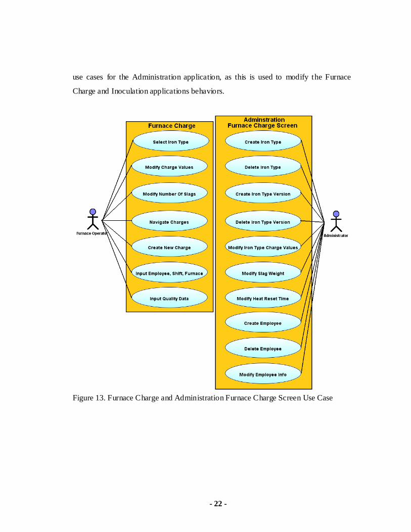
- 22 -
use cases for the Administration application, as this is used to modify the Furnace
Charge and Inoculation applications behaviors.
Figure 13. Furnace Charge and Administration Furnace Charge Screen Use Case

- 23 -
Figure 14. Inoculation and Administration Inoculation Screen Use Case

- 24 -
Figure 15. Casting Pour Use Case

- 25 -
Figure 16. Defect Analyzer Use Case

- 26 -
4. Design and Implementation Challenges
One of the most difficult aspects of a software engineering project is
balancing customers‟ needs versus customers‟ wishes, and achieving this in a
timeframe that is acceptable to both parties. The following list details the challenges
that were encountered during this project.
4.1 Scope Creep
With a paper file system so tightly integrated into Torrance Casting's day to
day operations, it was easy to envision replacing every step of the way with a
software application. Ultimately, a decision had to be made to finish the data
collection tools and defect analyzer software before progressing on to these other
ideas.
One example of scope creep and its solution is seen in the mold interface
application. Each day a production schedule is created detailing the castings that will
be produced by the foundry. The Inoculation application requires the user select the
molds to pour thus calculating the iron required. Initially, there was an idea of
creating an application to produce the production schedule and integrate it with the
Inoculation application. After analysis and developing a prototype, it became clear
that the complexity of tying these two processes together was well outside the scope
of the project, but the data associated with each mold was still required for the
Inoculation application to function properly. The solution for this was the Mold
Interface application; it would pull the necessary mold data from a legacy system
without the unnecessary complexity that the production schedule application would
have added.

- 27 -
4.2 Schedules of Prototypes
Since this application suite was replacing a paper intensive process and no
existing software solution to use as a guide, the prototyping method seemed like a
logical fit. However, this method proved to be very time consuming. The Lean
Foundry application suite consists of several separate applications that are tightly
integrated with the data model. It means that changes in one application usually
result in changes in other applications and so the development usually had to be
finished on one application before moving onto the next application. This serial
approach to development posed great challenges to finish prototypes at scheduled
milestones of the current project.
4.3 Database Architecture
A simple normalized database design was envisioned at the start of the
project, but this ran into problems early on in the project. An example of the problem
occurs on the Furnace Charge application. When the furnace operator creates a new
furnace charge, the required weights of the iron type are filled with initial values.
The customer would like to store these initial values so that a comparison can be
made between them and the values the furnace operator changes them to. The initial
design simply stored the iron types' primary key in the charge table along with the
final weights. This caused a problem when the administrator updated the record of
that iron type at a later date. The historical initial values for that iron type would be
essentially lost.
One solution to this problem was a point in time architecture. This
architecture requires every record to have effective and end dates associated with it.
Deletions are not allowed; instead, the end date is updated to the current date to show
when this "soft" delete occurred. Updates are performed by updating the end date of

- 28 -
the record and inserting a new record with a new effective date. This architecture
proved extremely hard to execute, and was abandoned because of the complexity.
Ultimately it was decided that the best solution would be to introduce some
redundancy in the data. The initial values the customer wanted would be stored
along with the final values of the furnace charge. Although this solution may require
more storage space, the relative cheap cost of storage vastly outweighed the
complexity of the other solutions to this problem.

- 29 -
5. Detailed Design
The Lean Foundry application suite consists of six separate applications
implemented with an object-oriented approach. Each application was split into
multiple layers. A UML class diagram and design notes for each application follows.
5.1 Furnace Charge and Mold Interface Design
The Furnace Charge and Mold Interface software are each split into three
layers. The UML class diagrams and notes on each design follow.
The first layer (not pictured) contains the database where the data from the
Furnace Charge application is stored and shared amongst all the
applications in the Lean Foundry suite.
The second layer contains data objects which facilitate all the data
processing needs of the application.
The third layer contains the graphical user interface and the business logic.
All user interactions with the application occur through this layer.
The DatabaseUtility class serves as a central location to store all the logic
required for opening connections to the database, closing connections, and
error handling. Each data object in the second layer gets an instance of the
DatabaseUtility to handle its connection to the database.

- 30 -
Figure 17. UML Class Diagram for Furnace Charge application

- 31 -
Figure 18. UML Class Diagram for Mold Interface application
5.2 Inoculation, Casting Pour, Administrator, and Defect
Analyzer Design
The Inoculation, Casting Pour, Administrator, and Defect Analyzer are each
split into four layers. The UML class diagrams and notes on each design follow.
The first layer (not pictured) contains the database where the data from the
Inoculation application is stored and shared amongst all the applications in the
Lean Foundry suite.
The second layer contains data objects which facilitate all the data processing
needs of the application.
The third layer contains TableModel classes. A TableModel class is used by
the Java language to represent the data source of a JTable in the GUI layer.

- 32 -
The TableModel layer contains an array of data objects from the previous
layer along with other logic required by the JTable class.
The fourth layer contains the graphical user interface and the business logic.
All user interactions with the application occur through this layer.
The DatabaseUtility class serves as a central location to store all the logic
required for opening connections to the database, closing connections, and
error handling. Each data object in the second layer, and each TableModel in
the third layer gets an instance of the DatabaseUtility to handle its connection
to the database.

- 33 -
Figure 19. UML Class Diagram for Inoculation application

- 34 -
Figure 20. UML Class Diagram for CastingPour application

- 35 -
Figure 21. UML Class Diagram for Administrator application

- 36 -
Figure 22. UML Class Diagram for Defect Analyzer application
5.3 Database Design
Figure 19 shows a simplified database diagram for the LeanFoundry suite.
The diagram shows the primary and foreign keys used to join the tables together in
the system. A full listing of the LeanFoundry table layout can be found in Appendix
A.

- 37 -
Figure 23. Simplified Database Diagram for Lean Foundry Tables

- 38 -
6. Coding and Implementation
After the initial meeting with the sponsor (Torrance Casting), it was evident
that a prototyping model would be the best approach. Since the main focus of the
project was data collection and storage, if the software slows down or impedes the
casting process in any way, it would be a failure. With only a paper system in place,
the sponsor was willing to allow prototypes to be used in conjunction with the paper
system. This allowed the sponsor and end users to visualize, test, and give instant
feedback on the software. The feedback was then reviewed with the sponsor and was
then implemented in the next prototype. The new prototype was installed in the
foundry and the process was repeated. This process continued until the software
satisfied both parties.
The technologies required to develop the Lean Foundry application suite were
chosen by the developer based upon familiarity and cost. The applications were
programmed using the Java programming language and NetBeans IDE, both which
are provided at no cost. The open source MySql database was selected for data
storage which also is available free of charge.
With the many applications involved in the Lean Foundry suite, coupled with
the constant revisions caused by the prototyping method, the database structure was
in a constant state of change. The applications share many of the data objects along
with database tables, thus presenting a maintenance problem anytime a change was
desired.
The solution to maintaining the data objects was found in the development of
a tool that would auto-generate the Java code based upon the underlying database
table structure. When a change was made to a database table, the tool would be run

- 39 -
against the newly created table and a new data object would be created with proper
methods, properties, and database sequel statements. Any custom code added to the
previous version of the data object would have to be copied over manually, but the
time savings were tremendous.
The data objects were coded with the ability to load, update, and delete any
data related to the object. To increase efficiency of the applications, a mechanism
was created to track whether the data class was new or had been updated. If the data
was new or had been updated the data object was considered "dirty". The
applications frequently save the values from the data objects into the database. When
this occurs, the data object wills only save the values if it is considered to be dirty,
thus saving the effort of saving existing data.
Two database environments were created on a server at Torrance Casting - a
production database, and a development database. The production database was used
by the applications when they had completed testing and were installed at the foundry
for customer use. The development database was used for prototype meetings and
testing. Since development of the application was done on the developer‟s
workstation, another production and development databases were created on the
developer‟s workstation. To reconcile all of these databases, a tool was developed to
maintain these databases. A table was created in each database called TBL_INFO.
This table contained the version number of the database structure. The database tool
had the code used to create every version of the database, so when connected to a
database, it could execute the sequel statements in the correct order to bring the
database up to the current version without data loss. This tool also allowed for the
easy copying of the production data into the development database for testing
purposes, or to output to text files which could then be loaded into the developer‟s
workstation.

- 40 -
7. Limitations
One of the major limitations of the LeanFoundry application suite is the
dependency each application has upon the other applications in the suite. A failure in
any one of the applications can ruin the integrity of the entire system, or a network
outage could render all of the applications useless. Torrance Casting cannot a fford
downtime due to application errors, therefore a backup paper system must be ready to
replace the system if need be.
Another limitation is the failure of the database. Backup procedures must be
implemented on the database to ensure that, in case of failure, adequate backups are
available to prevent loss of historical data. If the database becomes the main
repository for company information, then steps must be taken to ensure the existence
of this data in case of failure.
As the database grows in size, it may be necessary to analyze the speed of the
applications, and database queries to optimize them for speed. From a development
standpoint, it was hard to anticipate the speed of the application as the database
slowly accumulates several years worth or data. The database may even require some
of the older data to be archived onto a historical database to maintain acceptable
application speeds.
- 41 -
8. Continuing Work
There are several areas where the Lean Foundry software suite could be
improved upon if further work is desired. The following list denotes requirements
that were considered during the design of this project, but were ultimately rejected
due to time constraints.
Real time defect alerts. As defective castings are indentified, patterns may
emerge about what caused the defect. These patterns could then be used
in real time to either alert the administrator or the employee using the
application. Notifying them that the parameters they have entered have
caused defects in the past, possibly preventing future occurrences of this
defect.
Inventory management. When a customer orders a casting, the foundry
may produce extra castings and store these until the customer places
another order. The Lean Foundry software could be tied to the database to
keep accurate records on the inventory of these castings.
Molding schedule. Create the molding schedule in the Lean Foundry
application suite, allowing the user to add required castings throughout the
day. Also allowing the user to prioritize which castings should be
produced first.
Casting completion monitor. The office workers that take and fill the
orders for Torrance Casting customers would find it helpful to have an
application that displayed in real time the castings that have recently been
poured, and the remaining castings to pour for the customer.
Reporting application. With all the data collected from the Lean Foundry
application suite, a user friendly reporting application would be useful.

- 42 -
Mold production notes. Each casting comes with a set of instructions on
how to best create the casting. This information is gathered over
numerous times during the production of the casting. Displaying this data
in the application and making it updatable would be very helpful.
Casting pictures. Pictures of each casting could be implemented into the
applications to make identification easier.
Shakeout table application. When a new casting is created, employees can
have a hard time distinguishing the casting from the extraneous metal that
must be removed from the casting during the shakeout process. An
application could be created that displays a picture of all recently poured
castings so that the employee will not mistake the casting from the waste.
Data mining for worker incentives. An application created to mine data
from the database showing worker productivity. This application would
be displayed in the lunch room or other common areas. The application
would display different statistics that management may chose to try
encourage better production from employees, offering cash incentives
upon meeting certain goals.

- 43 -
9. Conclusion
In conclusion, the Lean Foundry application suite was designed from the
ground up to replace existing paper processes. In addition, the software suite should
decrease waste by better prediction of the amount of iron required to fill an order of
castings. The Lean Foundry application suite has automated many of the data entry
tasks which should result in increased efficiency, and accuracy of data collection.
The inclusion of the Administrator application allows for easy configuration
of the entire application suite without the need of dedicated I.T. staff. The different
types of iron created by Torrance Casting are very dynamic in nature, possibly
changing with each delivery of new raw materials, the software allows an
administrator to create and update an unlimited number of iron types from any
computer on the network. This administrator application can also maintain
employees, default values, and several other configurable behaviors of the application
suite.
This application suite was designed to capture as much data as possible into a
centralized database, resulting in several benefits. The first benefit was the main
focus of this project, creating a central location for the data to be analyzed and assist
in determining the cause of defects. Another benefit of the centralized database
allows for the future expansion without loss of any historically data. As the data
repository grows, the ability to query the data may contribute to efficiencies and
process enhancements that are unforeseen at this time.
.

- 44 -
10. Bibliography
1. George Reese, Database Programming with JDBC and Java (Second
Edition), O'Reilly, 2000
Gary Entsminger, The Tao of Objects: A Beginners Guide to Object Oriented
Programming (Second Edition), M&T Books, 1995
2. Hans van Vliet, Software Engineering: Principles and Practice (Third
Edition), Wiley, 2008
3. Paul DuBois, MySql Developers Library (Fourth Edition), Addison Wesley,
2008
4. Peter van der Linden, Just Java 2 (Fourth Edition), Sun Microsystems Press,
1999
5. Robert L. Glass, Facts and Fallacies of Software Engineering (Agile Software
Development), Addison Wesley, 2002
6. Http://www.atlasfdry.com/glossary.htm, "Glossary of Foundry Terms", Atlas
Foundry Company.
7. Http://www.netbeans.org/, "Netbeans IDE reference"
8. Http://java.sun.com/, "Java reference"
9. Http://mysql.com/, "MySql database reference"
10. Http://www.torrancecasting.com/Foundry.htm, "Company History", Torrance
Casting.

- 45 -
Appendix A: Lean Foundry Table Layout Listing
Table Name: TBL_CASTING
Field Type Key
CASTING_ID int(11) Primary
MOLD_ID int(11)
CHARGE_ID int(11)
FURNACE_TAP_ID int(11)
LADLE_NO int(2)
CASTING_DATE datetime
CUSTOMER varchar(30)
PART_ID varchar(25)
IRON_TYPE_CD enum('','D','G','N')
TORRANCE_IRON_CD varchar(10)
INNOCULANT_ID int(11)
MOLD_WEIGHT int(11)
NUMBER_POURED int(11)
NUMBER_TO_POUR int(11)
MOLD_LINE_ID int(11)
BEGIN_TEMP int(6)
MID_TEMP int(6)
END_TEMP int(6)
TRANS_DATE timestamp
Table Name: TBL_CHARGE
Field Type Key
CHARGE_ID int(11) Primary
IRON_ID int(11)
VERSION_ID int(11)
IRON_TYPE_CD enum('','D','G','N')
FURNACE_NO int(2)

- 44 -
SHIFT_NO int(2)
EMPLOYEE_ID int(11)
CHARGE_DATE datetime
HEAT_NO int(3)
SLAG_NO int(2)
TOTAL_SLAG_WEIGHT double(7,2)
SOREL_PIG double(7,2)
SOREL_PIG_INIT double(7,2)
NODULAR_PIG double(7,2)
NODULAR_PIG_INIT double(7,2)
BESSEMER_PIG double(7,2)
BESSEMER_PIG_INIT double(7,2)
BASIC_PIG double(7,2)
BASIC_PIG_INIT double(7,2)
STEEL double(7,2)
STEEL_INIT double(7,2)
RETURN_GRAY_IRON double(7,2)
RETURN_GRAY_IRON_INIT double(7,2)
RETURN_DUCTILE_K double(7,2)
RETURN_DUCTILE_K_INIT double(7,2)
RETURN_DUCTILE_L double(7,2)
RETURN_DUCTILE_L_INIT double(7,2)
RETURN_NI_HARD_IRON double(7,2)
RETURN_NI_HARD_IRON_INIT double(7,2)
RETURN_DUCTILE_C double(7,2)
RETURN_DUCTILE_C_INIT double(7,2)
RETURN_DUCTILE_AAA double(7,2)
RETURN_DUCTILE_AAA_INIT double(7,2)
CARBON double(7,2)
CARBON_INIT double(7,2)
SILICON_CARBIDE double(7,2)
SILICON_CARBIDE_INIT double(7,2)
FESI_75 double(7,2)
FESI_75_INIT double(7,2)
FEMN double(7,2)
FEMN_INIT double(7,2)
COPPER double(7,2)
COPPER_INIT double(7,2)
IRON_PYRITE double(7,2)
IRON_PYRITE_INIT double(7,2)

- 45 -
PHOSPHOROUS double(7,2)
PHOSPHOROUS_INIT double(7,2)
NICKEL_PELLETS double(7,2)
NICKEL_PELLETS_INIT double(7,2)
FERROCHROME double(7,2)
FERROCHROME_INIT double(7,2)
CARBON_TRIM double(7,2)
SILICON_CARBIDE_TRIM double(7,2)
FESI_75_TRIM double(7,2)
FEMN_TRIM double(7,2)
COPPER_TRIM double(7,2)
IRON_PYRITE_TRIM double(7,2)
PHOSPHOROUS_TRIM double(7,2)
NICKEL_PELLETS_TRIM double(7,2)
FERROCHROME_TRIM double(7,2)
ACEL_1 double(7,2)
ACEL_2 double(7,2)
ACEL_3 double(7,2)
ACEL_4 double(7,2)
C_1 double(7,2)
C_2 double(7,2)
C_3 double(7,2)
C_4 double(7,2)
TEMP_1 int(6)
TEMP_2 int(6)
TEMP_3 int(6)
TEMP_4 int(6)
TRANS_DATE timestamp
Table Name: TBL_DEFECT
Field Type Key
DEFECT_ID int(11) Primary
CASTING_ID int(11)
DEFECT varchar(5000)
TRANS_DATE timestamp

- 46 -
Table Name: TBL_EMPLOYEE
Field Type Key
EMPLOYEE_ID int(11) Primary
CLOCK_NO int(6)
FIRST_NAME varchar(45)
LAST_NAME varchar(45)
FURNACE_OPERATOR tinyint(1)
SHIFTER tinyint(1)
POURER tinyint(1)
TRANS_DATE Timestamp
Table Name: TBL_FURNACE_TAP
Field Type Key
FURNACE_TAP_ID int(11) Primary
CHARGE_ID int(11)
TAP_DATE datetime
TAP_NO int(6)
IRON_TYPE_CD enum('','D','G','N')
LADLE_1_INOCULANT_ID int(11)
LADLE_2_INOCULANT_ID int(11)
DUCTILE_TARGET_WEIGHT int(11)
TUNDISH_FESIMG double(7,2)
FESI_COVER double(7,2)
LADLE_1_LUMP_FESI75 double(7,2)
LADLE_1_SUPERSEED double(7,2)
LADLE_1_ULTRASEED double(7,2)
LADLE_1_COPPER double(7,2)
LADLE_1_CHROME double(7,2)
LADLE_1_NICKEL double(7,2)
LADLE_1_FESI75 double(7,2)
LADLE_1_STEEL double(7,2)
LADLE_1_MOLD_WEIGHT int(11)
LADLE_1_TARGET_WEIGHT int(11)
LADLE_1_ACTUAL_WEIGHT int(11)
LADLE_1_SPILLAGE_WEIGHT int(11)
LADLE_1_CHILL_WEIGHT int(11)
LADLE_1_TEST_BAR_COUNT int(11)
LADLE_1_TOTAL_TEST_BAR_WEIGHT int(11)

- 47 -
LADLE_1_POURER_EMPLOYEE_ID int(11)
LADLE_1_POUR_STATUS_CD enum('','C','A')
LADLE_2_SUPERSEED double(7,2)
LADLE_2_ULTRASEED double(7,2)
LADLE_2_COPPER double(7,2)
LADLE_2_CHROME double(7,2)
LADLE_2_NICKEL double(7,2)
LADLE_2_FESI75 double(7,2)
LADLE_2_STEEL double(7,2)
LADLE_2_MOLD_WEIGHT int(11)
LADLE_2_TARGET_WEIGHT int(11)
LADLE_2_ACTUAL_WEIGHT int(11)
LADLE_2_SPILLAGE_WEIGHT int(11)
LADLE_2_CHILL_WEIGHT int(11)
LADLE_2_TEST_BAR_COUNT int(11)
LADLE_2_TOTAL_TEST_BAR_WEIGHT int(11)
LADLE_2_POURER_EMPLOYEE_ID int(11)
LADLE_2_POUR_STATUS_CD enum('','C','A')
TRANS_DATE timestamp
Table Name: TBL_INFO
Field Type Key
INFO_ID varchar(10)
INFO varchar(100)
Table Name: TBL_INOCULANT
Field Type Key
INOCULANT_ID int(11) Primary
INOCULANT_NAME varchar(45)
IRON_TYPE_CD enum('','D','G','N')
TUNDISH_FESIMG_RATIO double(8,6)
FESI_COVER_RATIO double(8,6)
LUMP_FESI75_RATIO double(8,6)
SUPERSEED_RATIO double(8,6)
ULTRASEED_RATIO double(8,6)
COPPER_RATIO double(8,6)

- 48 -
CHROME_RATIO double(8,6)
NICKEL_RATIO double(8,6)
FESI75_RATIO double(8,6)
STEEL_RATIO double(8,6)
ACTIVE tinyint(1)
TRANS_DATE timestamp
Table Name: TBL_IRON
Field Type Key
IRON_ID int(11) Primary
IRON_TYPE_CD enum('','D','G','N')
IRON_NAME varchar(45)
TRANS_DATE Timestamp
Table Name: TBL_IRON_VERSION
Field Type Key
VERSION_ID int(11) Primary
IRON_ID int(11)
VERSION_NO int(4)
TARGET_ACEL varchar(25)
TARGET_CARBON varchar(25)
BASIC_PIG_ACTIVE tinyint(1)
BASIC_PIG_INIT double(7,2)
BASIC_PIG_MIN double(7,2)
BASIC_PIG_MAX double(7,2)
BASIC_PIG_AVG int(3)
BASIC_PIG_WARN tinyint(1)
BASIC_PIG_ALLOW tinyint(1)
BESSEMER_PIG_ACTIVE tinyint(1)
BESSEMER_PIG_INIT double(7,2)
BESSEMER_PIG_MIN double(7,2)
BESSEMER_PIG_MAX double(7,2)
BESSEMER_PIG_AVG int(3)
BESSEMER_PIG_WARN tinyint(1)
BESSEMER_PIG_ALLOW tinyint(1)
CARBON_ACTIVE tinyint(1)

- 49 -
CARBON_INIT double(7,2)
CARBON_MIN double(7,2)
CARBON_MAX double(7,2)
CARBON_AVG int(3)
CARBON_WARN tinyint(1)
CARBON_ALLOW tinyint(1)
COPPER_ACTIVE tinyint(1)
COPPER_INIT double(7,2)
COPPER_MIN double(7,2)
COPPER_MAX double(7,2)
COPPER_AVG int(3)
COPPER_WARN tinyint(1)
COPPER_ALLOW tinyint(1)
FEMN_ACTIVE tinyint(1)
FEMN_INIT double(7,2)
FEMN_MIN double(7,2)
FEMN_MAX double(7,2)
FEMN_AVG int(3)
FEMN_WARN tinyint(1)
FEMN_ALLOW tinyint(1)
FERROCHROME_ACTIVE tinyint(1)
FERROCHROME_INIT double(7,2)
FERROCHROME_MIN double(7,2)
FERROCHROME_MAX double(7,2)
FERROCHROME_AVG int(3)
FERROCHROME_WARN tinyint(1)
FERROCHROME_ALLOW tinyint(1)
FESI75_ACTIVE tinyint(1)
FESI75_INIT double(7,2)
FESI75_MIN double(7,2)
FESI75_MAX double(7,2)
FESI75_AVG int(3)
FESI75_WARN tinyint(1)
FESI75_ALLOW tinyint(1)
IRON_PYRITE_ACTIVE tinyint(1)
IRON_PYRITE_INIT double(7,2)
IRON_PYRITE_MIN double(7,2)
IRON_PYRITE_MAX double(7,2)
IRON_PYRITE_AVG int(3)
IRON_PYRITE_WARN tinyint(1)

- 50 -
IRON_PYRITE_ALLOW tinyint(1)
NICKEL_PELLETS_ACTIVE tinyint(1)
NICKEL_PELLETS_INIT double(7,2)
NICKEL_PELLETS_MIN double(7,2)
NICKEL_PELLETS_MAX double(7,2)
NICKEL_PELLETS_AVG int(3)
NICKEL_PELLETS_WARN tinyint(1)
NICKEL_PELLETS_ALLOW tinyint(1)
NODULAR_PIG_ACTIVE tinyint(1)
NODULAR_PIG_INIT double(7,2)
NODULAR_PIG_MIN double(7,2)
NODULAR_PIG_MAX double(7,2)
NODULAR_PIG_AVG int(3)
NODULAR_PIG_WARN tinyint(1)
NODULAR_PIG_ALLOW tinyint(1)
PHOSPHOROUS_ACTIVE tinyint(1)
PHOSPHOROUS_INIT double(7,2)
PHOSPHOROUS_MIN double(7,2)
PHOSPHOROUS_MAX double(7,2)
PHOSPHOROUS_AVG int(3)
PHOSPHOROUS_WARN tinyint(1)
PHOSPHOROUS_ALLOW tinyint(1)
RETURN_DUCTILE_AAA_ACTIVE tinyint(1)
RETURN_DUCTILE_AAA_INIT double(7,2)
RETURN_DUCTILE_AAA_MIN double(7,2)
RETURN_DUCTILE_AAA_MAX double(7,2)
RETURN_DUCTILE_AAA_AVG int(3)
RETURN_DUCTILE_AAA_WARN tinyint(1)
RETURN_DUCTILE_AAA_ALLOW tinyint(1)
RETURN_DUCTILE_C_ACTIVE tinyint(1)
RETURN_DUCTILE_C_INIT double(7,2)
RETURN_DUCTILE_C_MIN double(7,2)
RETURN_DUCTILE_C_MAX double(7,2)
RETURN_DUCTILE_C_AVG int(3)
RETURN_DUCTILE_C_WARN tinyint(1)
RETURN_DUCTILE_C_ALLOW tinyint(1)
RETURN_DUCTILE_K_ACTIVE tinyint(1)
RETURN_DUCTILE_K_INIT double(7,2)
RETURN_DUCTILE_K_MIN double(7,2)
RETURN_DUCTILE_K_MAX double(7,2)

- 51 -
RETURN_DUCTILE_K_AVG int(3)
RETURN_DUCTILE_K_WARN tinyint(1)
RETURN_DUCTILE_K_ALLOW tinyint(1)
RETURN_DUCTILE_L_ACTIVE tinyint(1)
RETURN_DUCTILE_L_INIT double(7,2)
RETURN_DUCTILE_L_MIN double(7,2)
RETURN_DUCTILE_L_MAX double(7,2)
RETURN_DUCTILE_L_AVG int(3)
RETURN_DUCTILE_L_WARN tinyint(1)
RETURN_DUCTILE_L_ALLOW tinyint(1)
RETURN_GRAY_IRON_ACTIVE tinyint(1)
RETURN_GRAY_IRON_INIT double(7,2)
RETURN_GRAY_IRON_MIN double(7,2)
RETURN_GRAY_IRON_MAX double(7,2)
RETURN_GRAY_IRON_AVG int(3)
RETURN_GRAY_IRON_WARN tinyint(1)
RETURN_GRAY_IRON_ALLOW tinyint(1)
RETURN_NIHARD_ACTIVE tinyint(1)
RETURN_NIHARD_INIT double(7,2)
RETURN_NIHARD_MIN double(7,2)
RETURN_NIHARD_MAX double(7,2)
RETURN_NIHARD_AVG int(3)
RETURN_NIHARD_WARN tinyint(1)
RETURN_NIHARD_ALLOW tinyint(1)
SILICON_CARBIDE_ACTIVE tinyint(1)
SILICON_CARBIDE_INIT double(7,2)
SILICON_CARBIDE_MIN double(7,2)
SILICON_CARBIDE_MAX double(7,2)
SILICON_CARBIDE_AVG int(3)
SILICON_CARBIDE_WARN tinyint(1)
SILICON_CARBIDE_ALLOW tinyint(1)
SOREL_PIG_ACTIVE tinyint(1)
SOREL_PIG_INIT double(7,2)
SOREL_PIG_MIN double(7,2)
SOREL_PIG_MAX double(7,2)
SOREL_PIG_AVG int(3)
SOREL_PIG_WARN tinyint(1)
SOREL_PIG_ALLOW tinyint(1)
STEEL_ACTIVE tinyint(1)
STEEL_INIT double(7,2)

- 52 -
STEEL_MIN double(7,2)
STEEL_MAX double(7,2)
STEEL_AVG int(3)
STEEL_WARN tinyint(1)
STEEL_ALLOW tinyint(1)
ACTIVE tinyint(1)
TRANS_DATE Timestamp
Table Name: TBL_MOLD
Field Type Key
MOLD_ID int(11) Primary
CUSTOMER varchar(30)
PART_ID varchar(25)
IRON_TYPE_CD enum('','D','G','N')
TORRANCE_IRON_CD varchar(10)
MOLD_WEIGHT int(11)
TRANS_DATE Timestamp
Table Name: TBL_MOLD_LINE
Field Type Key
MOLD_LINE_ID int(11) Primary
MOLD_LINE varchar(25)
Table Name: TBL_PARAMETER
Field Type Key
PARAMETER_ID varchar(10) Primary
PARAMETER_VALUE varchar(500)