
defaust1000c_pt15_sep09
202
UNCONTROLLED COPY WHEN PRINTED DEF(AUST)1000C PART 15 / Issue 2 Dated Sep 2009 SUPERSEDING DEF(AUST)1000C PART 15 Original Issue Dated July 2000 ADF PACKAGING; PART 15: PACKAGING SPECIFICATIONS AND CLASSIFICATION SYSTEMS STANDARD * PUBLISHED UNDER AUTHORITY OF DEPARTMENT OF DEFENCE USAGE: Maritime Land Air NSC: PACK DEPARTMENT OF DEFENCE NOTICE THIS ON-LINE PUBLICATION IS A CONTROLLED COPY OF DEF(AUST)1000C, PART 15. CONFIM ISSUE STATUS BEFORE USE - CONTACT LAND ENGINEERING AGENCY, TECHNICAL DATA CENTRE + mailto:[email protected] WHEN PRINTED THIS PUBLICATION IS AN UNCONTROLLED COPY AND IS NOT SUBJECT TO UPDATE OR AMENDMENT ACTION. AUSTRALIAN GOVERNMENT AUSTRALIAN DEFENCE STANDARD
-
Upload
jinjuriki1983 -
Category
Documents
-
view
118 -
download
0
Transcript of defaust1000c_pt15_sep09

UNCONTROLLED COPY WHEN PRINTED
DEF(AUST)1000C PART 15 / Issue 2 Dated Sep 2009
SUPERSEDING
DEF(AUST)1000C PART 15 Original Issue Dated July 2000
AADDFF PPAACCKKAAGGIINNGG;;
PPAARRTT 1155:: PPAACCKKAAGGIINNGG
SSPPEECCIIFFIICCAATTIIOONNSS AANNDD
CCLLAASSSSIIFFIICCAATTIIOONN SSYYSSTTEEMMSS
SSTTAANNDDAARRDD **
PPUUBBLLIISSHHEEDD UUNNDDEERR AAUUTTHHOORRIITTYY
OOFF DDEEPPAARRTTMMEENNTT OOFF DDEEFFEENNCCEE
USAGE: Maritime Land Air NSC: PACK
DEPARTMENT OF DEFENCE NOTICE
THIS ON-LINE PUBLICATION IS A CONTROLLED COPY OF DEF(AUST)1000C, PART 15.
CONFIM ISSUE STATUS BEFORE USE - CONTACT LAND ENGINEERING AGENCY,
TECHNICAL DATA CENTRE + mailto:[email protected]
WHEN PRINTED THIS PUBLICATION IS AN UNCONTROLLED COPY AND IS NOT SUBJECT TO
UPDATE OR AMENDMENT ACTION.
AUSTRALIAN GOVERNMENT
AUSTRALIAN DEFENCE STANDARD
DEF(AUST)1000C
PART 15
ii UNCONTROLLED COPY WHEN PRINTED
DEF(AUST) 1000C
DOCUMENT MANAGEMENT INFORMATION
Sponsoring Defence Group: Defence Materiel Organisation
Sponsoring Organisation: Land Systems Division
Sponsoring Appointment: DGLEA
Specification Author: Defence Packaging Committee Approved: 23 Jul 09
Approval Authority: DGLEA Approved: 28 Sep 09
Executive Authority: LEA -SEM Approved: 24 Sep 09
Prepared by the Defence Packaging Committee
The following Government, and industry organisations were consulted during the preparation
of this document: ARMY, RAN and RAAF DNSDC JLC
Published by:
Army Standardisation
This document is the property of the Department of Defence

DEF(AUST)1000C
PART 15
iii UNCONTROLLED COPY WHEN PRINTED
AMENDMENT LIST
Amendment Effected
No Date of Issue SIGNATURE Date Incorporated
Revision Note
This document supersedes: DEF(AUST)1000C PART 15 dated July 2000
Historical Record
First issued as DEF(AUST)1000C PART 15 dated July 2000 This Standard supersedes Australian Standard AS 2838: Classification System for Corrugated and Solid Fibreboard as approved by PK/5. It also supersedes by collating information from the following specifications: DEF(AUST)5538, Fibreboard, Corrugated, Triple wall, Sheet and Boxes. DEF(AUST)5611, Fibreboard, Corrugated: For packaging of Explosives and Ammunition Stores. DEF(AUST)5620A, Boxes and Sheet, Fibreboard, General Purpose. DEF(AUST)5636, Boxes, Wood, General Purpose. DEF(AUST)5668, Fibreboard Corrugated Classification (Based on Short Column Crush Values). DEF(AUST)5674, Design and Construction of Transport and Storage Containers. DEF(AUST)5675, Boxes Wood, Panel Style up to 0.5M
3 Capacity to Suit 1100mm Module Palletised
Load. DEF(AUST)6111, Crates, Shipping (Wood).

DEF(AUST)1000C
PART 15
iv UNCONTROLLED COPY WHEN PRINTED
Blank Page
DEF(AUST)1000C
PART 15
5 UNCONTROLLED COPY WHEN PRINTED
AUSTRALIAN DEFENCE STANDARD
DEF(AUST)1000C
ADF PACKAGING;
PART 15 PACKAGING SPECIFICATIONS AND
CLASSIFICATION SYSTEMS
STANDARD
SEPTEMBER 2009
Specific inquiries regarding the application of this standard to Requests for Tender or
contracts should be addressed to the Ordering Authority named in the Request for
Tender, or to the Quality Assurance Authority named in the contract, as appropriate.
Prepared by the Defence Packaging Committee (DPC) under the Authority of the
Defence Standardisation Coordination Group.
This Standard is mandatory for use by the RAN, Australian Army and RAAF, and
Contractors to the ADF.
WARNING (1)
This Standard may call for the use of substances and test procedures that may be injurious to
health if adequate precautions are not taken. It refers to technical suitability only and in no way absolves the supplier or user from statutory obligations relating to health and safety at any
stage of manufacture or use. WARNING (2)
For timber products (ie packaging, dunnage) that are to be forwarded overseas please be aware of AQIS conditions on the export or import of timber products. Information on timber
products is contained in DEF(AUST)1000, ADF Packaging, Part 10, AQIS Requirements, and
AQIS Requirements for the Australian Wood Packaging Certification Scheme (IPSM-15)
relevant information is contained at the following AQIS URL: http://www.daffa.gov.au/aqis/avm/military
WARNING (3)
Environmental Impact / Materiel Minimisation.
In order to comply with Defence waste minimisation policy, users are reminded of their
obligations to maximise use of recycled materials (where possible) and the intent of the National Packaging Covenant in material decisions. Further information is available at :
http://www.defence.gov.au/environment - waste
DEF(AUST)1000C is issued in 20 parts, with each part sub-divided into Sections. The 20 parts are:
PART 1: General Information1
PART 2: Packaging Requirements 1
PART 3: Packaging Practices and Materials1
PART 4: Standard Packaging Test Procedures 1
PART 5: Marking of Packages1
PART 6: Packaging of Dangerous Goods (Except Dangerous Goods
Class 1); Packaging Requirements and Packaging Mediums
1
PART 7: Packaging for Materiel Susceptible to Damage by
Electrostatic Discharge1

DEF(AUST)1000C
PART 15
6 UNCONTROLLED COPY WHEN PRINTED
PART 8: Defective Packaging Reporting System1
PART 9: Requirements for Reusable Containers1
PART 10: Australian Quarantine Inspection Service (AQIS)
Requirements1
PART 11: Unitisation1
PART 12: Bar Code Symbology1
PART 13: Packaging Material Catalogue PART 14: Minimum Packaging Specifications of Commercial Items
1
PART 15: Packaging Specifications and Classification Systems1
PART 16: Creative Brief Template PART 17: Packaging ILS Checklist
PART 18: Life Cycle Analysis
PART 19: Caching
PART 20: Techniques for Deployment, Packaging and Storage for Tropical Conditions
1 Denotes available at http://www.defence.gov.au/dmo/lsd/standards/def_aust_1000.cfm
Two or more parts may apply to any one packaging requirement and it is essential that all parts be
considered and used where appropriate.
This Standard does not apply to the packaging of ammunition and explosives (for packaging
information refer to EO Division – Munitions Branch). Further guidance available at URL: TBA
It should be noted that this standard might not be applicable to the packaging of materiel already
covered by detailed contractual packaging or production data. Examples are, but not limited to,
ammunition, explosives, non-commercial foodstuffs, POL, vehicles, small craft, clothing, arms, armament, telecommunications equipment and systems.
DEF(AUST)1000C
PART 15
vii UNCONTROLLED COPY WHEN PRINTED
1. FOREWORD
1.1 This PART is divided into the following material types:
SECTION A. Cartonboard/Fibreboard.
SECTION B.
NOTE: Preference is given to the use of timber that has been harvested in a sustainable way and is
recycled or reclaimed.
Sub Section B1: Boxes Wood, General Purpose
Sub Section B2: Boxes, Wood, Panel Style Up To 0.5m3
Sub Section B3: Design and Construction of Transport and Storage Containers
Sub Section B4: Crates Shipping (Wood)
SECTION C. Metal.
SECTION D. Polymers.
SECTION E. Composites.
SECTION F. Reserved.
1.2 Information in each PART provides detailed specifications that procurement agencies are able
to use.

DEF(AUST)1000C
PART 15
viii UNCONTROLLED COPY WHEN PRINTED
Blank Page

DEF(AUST)1000C
PART 15
9 UNCONTROLLED COPY WHEN PRINTED
PACKAGING SPECIFICATIONS AND CLASSIFICATION SYSTEMS
Para No Page
TABLE OF CONTENTS
1. FOREWORD ........................................................................................................... VII
SECTION A: FIBREBOARD
SUB SECTION A1: CLASSIFICATION SYSTEM FOR CORRUGATED AND SOLID FIBREBOARD
SPECIFICATION 1. PURPOSE .................................................................................................................. 17 2. SCOPE ....................................................................................................................... 17 3. APPLICABLE DOCUMENTS ................................................................................... 17 4. DEFINITIONS ........................................................................................................... 18 5. SAMPLING ............................................................................................................... 18 6. REQUIREMENTS ..................................................................................................... 18 ANNEX A - SAMPLING AND TEST SCHEDULE ................................................... 22
SUB SECTION A2: FIBREBOARD CORRUGATED CLASSIFICATION .............................................. 23 (BASED ON SHORT COLUMN CRUSH VALUES) .................................................................................. 23 1. SCOPE ....................................................................................................................... 23 2. CLASSIFICATION .................................................................................................... 23 3. APPLICABLE DOCUMENTS ................................................................................... 23 4. TERMINOLOGY ....................................................................................................... 24 5. REQUIREMENTS ..................................................................................................... 24
ANNEXDETERMINATION OF CHLORIDE ................................................................................................ 29 ANNEX B - DETERMINATION OF SULPHATE ......................................................................................... 31 ANNEX C - DETERMINATION OF ORGANIC ACIDITY ........................................................................... 33 ANNEX D - TEST FOR DELAMINATION IN WATER ................................................................................ 35
SUB SECTION A3: BOXES AND SHEET, FIBREBOARD, GENERAL PURPOSE ................................ 37 1. SCOPE ....................................................................................................................... 37 2. APPLICABLE DOCUMENTS ................................................................................... 38 3. DEFINITIONS ........................................................................................................... 39 4. REQUIREMENTS ..................................................................................................... 39 5. QUALITY ASSURANCE PROVISIONS ................................................................... 40 6. PREPARATION FOR DELIVERY ............................................................................ 41 DATA SHEET NO 1 - SHEET, FIBREBOARD, CORRUGATED AND SOLID ............................................ 42 DATA SHEET NO 2 - TYPE 1 - BOX FIBREBOARD, SOLID, REGULAR SLOTTED ................................ 45 DATA SHEET NO 3 - TYPE 2 - BOX, FIBREBOARD, CORRUGATED, SINGLE WALL ........................... 47 (DOUBLE FACED) REGULAR SLOTTED ............................................................... 47 DATA SHEET NO 4 - TYPE 3 - BOX, FIBREBOARD, CORRUGATED, DOUBLE WALL, REGULAR SLOTTED .................................................................................................................. 49 DATA SHEET NO 5 - TYPE 4 STYLE TW1 BOX, FIBREBOARD, CORRUGATED, TRIPLE WALL
REGULAR SLOTTED ............................................................................................... 51 DATA SHEET NO 6 - TYPE 4 STYLE TW2 BOX, FIBREBOARD, CORRUGATED, TRIPLE WALL ........ 53 COMPOSITE WRAP AROUND OVERLAPPING FLAP ........................................... 53 DATA SHEET NO 7 TYPE 4 STYLE TW3 BOX, FIBREBOARD, CORRUGATED, TRIPLE WALL ........ 57 COMPOSITE WRAP AROUND MEETING FLAP .................................................... 57 DATA SHEET NO 8 TYPE 4 STYLE TW4 BOX, FIBREBOARD, CORRUGATED, TRIPLE WALL ........ 61 COMPOSITE TOP OVERLAP ................................................................................... 61 DATA SHEET NO 9TYPE 5 STYLE TW5 BOX, FIBREBOARD, CORRUGATED, TRIPLE WALL ........... 65 HALF SLOTTED TOP ............................................................................................... 65 DATA SHEET NO 10 STYLE TW6 BOX, FIBREBOARD, CORRUGATED, TRIPLE WALL HALF SLOTTED WITH CAP ............................................................................................... 67 DATA SHEET NO 11 STYLE TW7 BOX, FIBREBOARD, CORRUGATED, TRIPLE WALL ..................... 69 SLEEVE WITH TOP AND BOTTOM CAPS ............................................................. 69
DEF(AUST)1000C
PART 15
10 UNCONTROLLED COPY WHEN PRINTED
Para No Page TABLE OF CONTENTS (Cont'd)
SECTION B: WOOD 73 SUB SECTION B1: BOXES WOOD, GENERAL PURPOSE (STANDARD SIZE RANGE FOR 1100 MM
PALLET) 1. SCOPE ....................................................................................................................... 73 2. APPLICABLE DOCUMENTS ................................................................................... 75 3. DEFINITIONS ........................................................................................................... 75 4. REQUIREMENTS ..................................................................................................... 76 5. QUALITY ASSURANCE PROVISIONS ................................................................... 80 6. PREPARATION FOR DELIVERY ............................................................................ 81 7. NOTES....................................................................................................................... 81 DATA SHEET NO.1 TYPE 1 - LIGHTWEIGHT CLASS 1 - TIMBER TYPE 1 - LIGHTWEIGHT ............. 85 CLASS 2 - NON-BATTENED ................................................................................... 85 DATA SHEET NO. 3 TYPE 1 - LIGHTWEIGHT CLASS 3 - BATTENED (6 MM TIMBER) ....................... 87 DATA SHEET NO.4 TYPE 1 - LIGHTWEIGHT CLASS 4 - BATTENED (12 MM TIMBER) .................... 91 DATA SHEET NO. 5 TYPE 2 - MEDIUMWEIGHT CLASS 1 - PLYWOOD PANEL CLEATED................ 95 DATA SHEET NO. 6 TYPE 2 - MEDIUMWEIGHT CLASS 2 - NON-BATTENED .................................... 97 DATA SHEET NO. 7 TYPE 2 - MEDIUMWEIGHT CLASS 3 - BATTENED .............................................. 99 DATA SHEET NO. 8 TYPE 2 - MEDIUMWEIGHT CLASS 4 - BATTENED, TWO-MAN LIFT .............. 101 DATA SHEET NO. 9 TYPE 3 - HEAVYWEIGHT CLASS 1 - BATTENED, MECHANICAL LIFT .......... 103 DATA SHEET NO. 10 TYPE 3 - HEAVYWEIGHT CLASS 2 - BATTENED, MECHANICAL LIFT, HEAVY
DUTY ...................................................................................................................... 105 DATA SHEET NO. 11 LIFTING HANDLES ............................................................................................... 107
SUB SECTION B2: BOXES, WOOD, PANEL STYLE UP TO 0.5M3
TO SUIT ...................................... 109 1100 MM MODULE PALLETISED LOAD .............................................................................................. 109
1. SCOPE ..................................................................................................................... 109 2. APPLICABLE DOCUMENTS ................................................................................. 109 3. DEFINITIONS ......................................................................................................... 110 4. REQUIREMENTS ................................................................................................... 111 5. QUALITY ASSURANCE PROVISIONS ................................................................. 116 6. PREPARATION FOR DELIVERY .......................................................................... 118 7. NOTES..................................................................................................................... 118 DATA SHEET NO. 1' TYPE 2 - MEDIUM WEIGHT BOXES STYLE A - PLYWOOD PANEL................. 119 DATA SHEET NO. 2 TYPE 2 - MEDIUM WEIGHT BOXES STYLE B - PLYWOOD PANEL (CLEATED
ENDS)...................................................................................................................... 121 DATA SHEET NO. 3 TYPE 2 - MEDIUM WEIGHT BOXES STYLE C - PLYWOOD PANEL (CLEATED
FULLY) ................................................................................................................... 123 DATA SHEET NO.4 TYPE 3 - HEAVY WEIGHT BOXES STYLE C - PLYWOOD CLEATED PANEL
MECHANICAL LIFT............................................................................................... 125 ANNEX A METHOD OF CLOSURE......................................................................................... 129 ANNEX B LIFTING HANDLES ............................................................................................... 133 ANNEX C HANDLING FACILITIES ........................................................................................ 139
SUB SECTION B3: DESIGN AND CONSTRUCTION OF TRANSPORT AND STORAGE
CONTAINERS ................................................................................................................................. 141 1. SCOPE ..................................................................................................................... 141 2. APPLICABLE DOCUMENTS ................................................................................. 141 3. DEFINITIONS ......................................................................................................... 142 4. REOUIREMENTS ................................................................................................... 142 5. QUALITY ASSURANCE PROVISIONS ................................................................. 149 6. NOTES..................................................................................................................... 150
ANNEX A ................................................................................................................................. 150 ANNEX B NAILING INSTRUCTION ....................................................................................... 153 ANNEX C PANEL STYLES ...................................................................................................... 154

DEF(AUST)1000C
PART 15
11 UNCONTROLLED COPY WHEN PRINTED
Para No Page
TABLE OF CONTENTS (Cont'd)
SUB SECTION B4: CRATES SHIPPING (WOOD)
1. SCOPE ..................................................................................................................... 161 2. APPLICABLE DOCUMENTS ................................................................................. 161 3. DEFINITIONS ......................................................................................................... 162 4. REQUIREMENTS ................................................................................................... 163 5. QUALITY ASSURANCE PROVISIONS ................................................................. 168 6. PREPARATION FOR DELIVERY .......................................................................... 168 7. NOTES..................................................................................................................... 169
DATA SHEET NO. 1 NAILING INSTRUCTIONS ..................................................................................... 171 DATA SHEET NO. 2 CLASS 1: CRATE, SHIPPING (WOOD, OPEN) STYLE 1: UP TO 50 KG .............. 173 DATA SHEET NO. 3 CLASS 1: CRATE SHIPPING (WOOD, OPEN) STYLE 2: UP TO 100 KG ............. 175 DATA SHEET NO. 4 CLASS 1: CRATE. SHIPPING (WOOD, OPEN) STYLE 3: UP TO 200 KG ............ 177 DATA SHEET NO. 5 CLASS 1: CRATE, SHIPPING (OPEN, WOOD) STYLE 4: UP TO 500 KG ............ 179 DATA SHEET NO. 6 CLASS 1: CRATE, SHIPPING (WOOD, OPEN) STYLE 5: UP TO 1000 KG .......... 181 DATA SHEET NO. 7 CLASS 2: CRATE, SHIPPING (WOOD, BOLTED AND SHEATHED)................... 183 STYLE 1: 1100 MM LENGTH AND 1100 DEPTH .................................................. 183 DATA SHEET NO. 8 CLASS 2: CRATE SHIPPING (WOOD, BOLTED AND SHEATHED).................... 187 STYLE 2: OVER 1100 MM LENGTH AND UP TO 1100 MM DEPTH ................... 187 DATA SHEET NO. 9 CLASS 2: CRATE, SHIPPING (WOOD, BOLTED AND SHEATHED)................... 191 STYLE 3: OVER 1100 MM LENGTH AND 1100 MM DEPTH ............................... 191
SECTION C: METALS ................................................................................................................................ 195
SECTION D: POLYMERS ........................................................................................................................... 196
SECTION E: COMPOSITES ........................................................................................................................ 197
SECTION F: OTHER (RESERVED) ............................................................................................................ 198
PUBLICATION IMPROVEMENT REPORT AND REPLY (PIRR) ............................................................. 199

DEF(AUST)1000C
PART 15
12 UNCONTROLLED COPY WHEN PRINTED
Para No Page TABLE OF FIGURES
FIGURE 1 THIS FIGURE ILLUSTRATES THE CODING SYSTEM AND THE METHOD OF STACKING
A PALLET. THE CODE OF THIS ILLUSTRATION IS M2.2.3 ............................................... 38 FIGURE 2 TYPE 1 BOX FIBREBOARD, SOLID,REGULAR SLOTTED..................................................... 45 FIGURE 3 TYPE 2 BOX ............................................................................................................................. 48 FIGURE 4 TYPE 3 BOX (NSN 8115-66-109-3668 SIZE CODE M.1X1X2 SHOWN) ................................ 50 FIGURE 5 TYPE 4 STYLE TW1 BOX .......................................................................................................... 52 FIGURE 6 STYLE TW2, FIBREBOARD, CORRUGATED, TRIPLE WALL COMPOSITE WRAP AROUND
OVERLAPPING FLAP ............................................................................................................. 54 FIGURE 7 A. FRAMED WOODEN. B. FRAMED TRIPLE WALL ...................................... 54 FIGURE 8 NAILING PATTERN................................................................................................................... 55 FIGURE 9 REINFORCING PLATE FOR USE WITH STANDARD SCREW NAIL ..................................... 55 FIGURE 10 SCREW NAIL WITH PLATE .................................................................................................... 55 FIGURE 11 SCREW NAIL WITH PLASTIC WASHER AND WAD ............................................................ 55 FIGURE 12 STYLE TW3, BOX FIBREBOARD, CORRUGATED, TRIPLE WALL COMPOSITE WRAP
AROUND MEETING FLAP ....................................................................................................... 58 FIGURE 13 TYPICAL ENDS FOR COMPOSITE BOX ................................................................................ 58 FIGURE 14 NAILING PATTERN ................................................................................................................. 59 FIGURE 15 REINFORCED PLATE FOR USE WITH STANDARD SCREW NAIL ..................................... 59 FIGURE 16 SCREW NAIL WITH PLATE .................................................................................................... 59 FIGURE 17 SCREW NAIL WITH PLASTIC WASHER AND WAD ............................................................ 59 FIGURE 18 STYLE TW2, BOX, FIBREBOARD, CORRUGATED, TRIPLE WALL .................................... 62 FIGURE 19 FRAMED WOODEN. B. FRAMED TRIPLE WALL ........................................ 62 FIGURE 20 NAIILING PATTERN ............................................................................................................... 62 FIGURE 21 REINFORCING PLATE FOR USE WITH STANDARD SCREW NAIL ................................... 63 FIGURE 22 SCREW NAIL WITH PLATE ..................................................................................................... 63 FIGURE 23 SCREW NAIL WITH PLASTIC WASHER AND WAD ............................................................ 63 FIGURE 24 STYLE TW5 BOX, FIBREBOARD, CORRUGATED, TRIPLE WALL HALF SLOTTED TOP
FOR PALLET USE ................................................................................................................... 66 FIGURE 25 STYLE TW6 BOX, FIBREBOARD, CORRUGATED, TRIPLE WALLHALF SLOTTED WITH
CAP........................................................................................................................................... 68 FIGURE 26 STYLE TW7 BOX, FIBREBOARD, CORRUGATED, TRIPLE WALL SLEEVE WITH TOP
AND BOTTOM CAPS .............................................................................................................. 70 FIGURE 27 SAMPLE BOX MARKING ........................................................................................................ 71 FIGURE 28 EXAMPLE OF BOX MARKING ................................................................................................ 71 FIGURE 29 CODING SYSTEM ..................................................................................................................... 74 FIGURE 30 END CONSTRUCTION ........................................................................................................... 77 FIGURE 31 END CONSTRUCTION ........................................................................................................... 77 FIGURE 32 NAILING PATTERN ................................................................................................................ 78 FIGURE 33 BOX STYLE .............................................................................................................................. 84 FIGURE 34 BOX STYLE .............................................................................................................................. 86 FIGURE 35 BOX STYLE .............................................................................................................................. 89 FIGURE 36 BOX STYLE .............................................................................................................................. 93 FIGURE 37 BOX STYLE .............................................................................................................................. 96 FIGURE 38 BOX STYLE .............................................................................................................................. 98 FIGURE 39 BOX STYLE ............................................................................................................................ 100 FIGURE 40 BOX STYLE ............................................................................................................................ 102 FIGURE 41 BOX STYLE ............................................................................................................................ 104 FIGURE 42 BOX STYLE ............................................................................................................................ 106 FIGURE 43 TYPE A, METAL HANDLE .................................................................................................... 107 FIGURE 44 CODING SYSTEM ................................................................................................................. 112 FIGURE 45 END CONSTRUCTION ......................................................................................................... 115 FIGURE 46 NAILING PATTERN ............................................................................................................... 115 FIGURE 47 BOX STYLE A ........................................................................................................................ 120 FIGURE 48 BOX ASSEMBLED ................................................................................................................. 120 FIGURE 49 BOX STYLE B ........................................................................................................................ 122 FIGURE 50 BOX ASSEMBLED ................................................................................................................. 122 FIGURE 51 BOX STYLE C ........................................................................................................................ 124 FIGURE 52 BOX ASSEMBLED .................................................................................................................. 124 FIGURE 53 BASE CONSTRUCTION ......................................................................................................... 126
DEF(AUST)1000C
PART 15
13 UNCONTROLLED COPY WHEN PRINTED
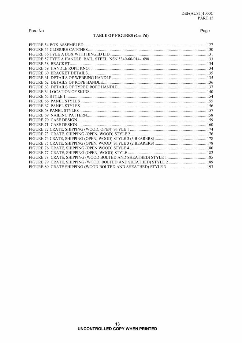
Para No Page TABLE OF FIGURES (Cont'd)
FIGURE 54 BOX ASSEMBLED .................................................................................................................. 127 FIGURE 55 CLOSURE CATCHES .............................................................................................................. 130 FIGURE 56 TYLE A BOX WITH HINGED LID.......................................................................................... 131 FIGURE 57 TYPE A HANDLE. BAIL. STEEL NSN 5340-66-014-1698 ..................................................... 133 FIGURE 58 BRACKET ............................................................................................................................... 134 FIGURE 59 HANDLE ROPE KNOT ........................................................................................................... 134 FIGURE 60 BRACKET DETAILS .............................................................................................................. 135 FIGURE 61 DETAILS OF WEBBING HANDLE ........................................................................................ 135 FIGURE 62 DETAILS OF ROPE HANDLE ................................................................................................ 136 FIGURE 63 DETAILS OF TYPE E ROPE HANDLE .................................................................................. 137 FIGURE 64 LOCATION OF SKIDS ............................................................................................................ 140 FIGURE 65 STYLE 1 ................................................................................................................................... 154 FIGURE 66 PANEL STYLES ..................................................................................................................... 155 FIGURE 67 PANEL STYLES ..................................................................................................................... 156 FIGURE 68 PANEL STYLES ...................................................................................................................... 157 FIGURE 69 NAILING PATTERN ............................................................................................................... 158 FIGURE 70 CASE DESIGN ........................................................................................................................ 159 FIGURE 71 CASE DESIGN ........................................................................................................................ 160 FIGURE 72 CRATE, SHIPPING (WOOD, OPEN) STYLE 1 ....................................................................... 174 FIGURE 73 CRATE. SHIPPING (OPEN, WOOD) STYLE 2 ...................................................................... 176 FIGURE 74 CRATE, SHIPPING (OPEN, WOOD) STYLE 3 (3 BEARERS) ................................................ 178 FIGURE 75 CRATE, SHIPPING (OPEN, WOOD) STYLE 3 (2 BEARERS) ................................................ 178 FIGURE 76 CRATE, SHIPPING (OPEN WOOD) STYLE 4 ....................................................................... 180 FIGURE 77 CRATE, SHIPPING (OPEN, WOOD) STYLE ......................................................................... 182 FIGURE 78 CRATE, SHIPPING (WOOD BOLTED AND SHEATHED) STYLE 1 .................................... 185 FIGURE 79 CRATE, SHIPPING (WOOD, BOLTED AND SHEATHED) STYLE 2 ................................... 189 FIGURE 80 CRATE SHIPPING (WOOD BOLTED AND SHEATHED) STYLE 3 ..................................... 193

DEF(AUST)1000C
PART 15
14 UNCONTROLLED COPY WHEN PRINTED
LIST OF TABLES PAGE
SECTION A: FIBREBOARD
SUB SECTION A1: CLASSIFICATION SYSTEM FOR CORRUGATED AND SOLID FIBREBOARD
SPECIFICATION
TABLE 1 CLASSIFICATION OF CORRUGATED FIBREBOARD.............................................................. 19 TABLE 2 CLASSIFICATION OF SOLID FIBREBOARD ............................................................................ 21 TABLE 3 SCHEDULE OF TESTS ................................................................................................................ 22 TABLE 4 CORRUGATED FIBREBOARD, DOMESTIC ............................................................................... 25 TABLE 5 CHEMICAL CHARACTERISTICS............................................................................................... 26 TABLE 6 CLASSIFICATION OF DEFECTS ................................................................................................ 27 TABLE 7 CLASSIFICATION OF DEFECTS ................................................................................................ 40 TABLE 8 CORRUGATED FIBREBOARD: FLUTE SPACING & HEIGHT ................................................. 42 TABLE 9 CORRUGATED FIBREBOARD: PROPERTIES ............................................................................ 43 TABLE 10 TYPE 2 - BOX FIBREBOARD, CORRUGATED, SINGLE WALL, DOUBLE FACED ............ 48 TABLE 11 TYPE 3 - BOX, FIBREBOARD, CORRUGATED, DOUBLE WALL REGULAR SLOTTED
SIZE RANGE ......................................................................................................................................... 50 TABLE 12 TYPE 4 - STYLE TW1 BOX FIBREBOARD, CORRUGATED, TRIPLE WALL, REGULAR
SLOTTED SIZE RANGE ....................................................................................................................... 52 TABLE 13 RECOMMENDED TIMBERS ...................................................................................................... 76 TABLE 14 CLASSIFICATION OF DEFECTS .............................................................................................. 80 TABLE 15 MATERIALS LIST ..................................................................................................................... 83 TABLE 16 NUMBER OF BOARDS .............................................................................................................. 84 TABLE 17 SIZE RANGE .............................................................................................................................. 84 TABLE 18 MATERIALS LIST ..................................................................................................................... 85 TABLE 19 NUMBER OF BOARDS .............................................................................................................. 86 TABLE 20 SIZE RANGE .............................................................................................................................. 86 TABLE 21 MATERIALS LIST ..................................................................................................................... 87 TABLE 22 NUMBER OF BOARDS .............................................................................................................. 88 TABLE 23 SIZE RANGE .............................................................................................................................. 88 TABLE 24 MATERIALS LIST ..................................................................................................................... 91 TABLE 25 NUMBER OF BOARDS .............................................................................................................. 92 TABLE 26 SIZE RANGE .............................................................................................................................. 92 TABLE 27 MATERIALS LIST ..................................................................................................................... 95 TABLE 28 SIZE RANGE .............................................................................................................................. 96 TABLE 29 MATERIALS LIST ..................................................................................................................... 97 TABLE 30 NUMBER OF BOARDS .............................................................................................................. 98 TABLE 31 SIZE RANGE .............................................................................................................................. 98 TABLE 32 MATERIALS LIST ..................................................................................................................... 99 TABLE 33 NUMBER OF BOARDS ............................................................................................................ 100 TABLE 34 SIZE RANGE ............................................................................................................................ 100 TABLE 35 MATERIALS LIST ................................................................................................................... 101 TABLE 36 NUMBER OF BOARDS ............................................................................................................ 102 TABLE 37 SIZE RANGE ............................................................................................................................ 102 TABLE 38 MATERIALS LIST ................................................................................................................... 103 TABLE 39 NUMBER OF BOARDS ............................................................................................................ 104 TABLE 40 SIZE RANGE ............................................................................................................................ 104 TABLE 41 MATERIALS LIST ................................................................................................................... 105 TABLE 42 NUMBER OF BOARDS ............................................................................................................ 106 TABLE 43 SIZE RANGE ............................................................................................................................ 106 TABLE 44 CLASSIFICATION OF DEFECTS ............................................................................................ 118 TABLE 45 MATERIALS LIST ................................................................................................................... 119 TABLE 46 SIZE RANGE ............................................................................................................................ 120 TABLE 47 MATERIALS LIST ................................................................................................................... 121 TABLE 48 .................................................................................................................................................... 122 TABLE 49 MATERIALS LIST ................................................................................................................... 123 TABLE 50 SIZE RANGE ............................................................................................................................ 124 TABLE 51 MATERIALS LIST .................................................................................................................... 125 TABLE 52 SIZE RANGE ............................................................................................................................. 126 TABLE 53 SELECTION OF HANDLING AIDS ......................................................................................... 139
DEF(AUST)1000C
PART 15
15 UNCONTROLLED COPY WHEN PRINTED
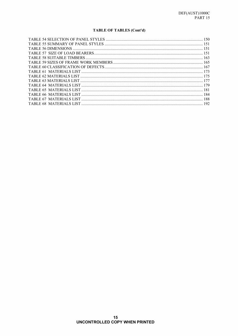
TABLE OF TABLES (Cont'd)
TABLE 54 SELECTION OF PANEL STYLES ............................................................................................ 150 TABLE 55 SUMMARY OF PANEL STYLES ............................................................................................. 151 TABLE 56 DIMENSIONS ........................................................................................................................... 151 TABLE 57 SIZE OF LOAD BEARERS ....................................................................................................... 151 TABLE 58 SUITABLE TIMBERS ............................................................................................................... 163 TABLE 59 SIZES OF FRAME WORK MEMBERS ..................................................................................... 165 TABLE 60 CLASSIFICATION OF DEFECTS ............................................................................................. 167 TABLE 61 MATERIALS LIST ................................................................................................................... 173 TABLE 62 MATERIALS LIST .................................................................................................................... 175 TABLE 63 MATERIALS LIST .................................................................................................................... 177 TABLE 64 MATERIALS LIST ................................................................................................................... 179 TABLE 65 MATERIALS LIST ................................................................................................................... 181 TABLE 66 MATERIALS LIST ................................................................................................................... 184 TABLE 67 MATERIALS LIST ................................................................................................................... 188 TABLE 68 MATERIALS LIST ................................................................................................................... 192

DEF(AUST)1000C
PART 15
16 UNCONTROLLED COPY WHEN PRINTED
Blank Page

DEF(AUST)1000C
PART 15
SECTION A
SUB SECTION A1
17 UNCONTROLLED COPY WHEN PRINTED
SECTION A: FIBREBOARD
SUB SECTION A1: CLASSIFICATION SYSTEM FOR CORRUGATED AND SOLID
FIBREBOARD SPECIFICATION
1. PURPOSE
1.1 This Standard will enable procurement, and ordering authorities to procure the appropriate
corrugated or solid fibreboard.
2. SCOPE
2.1 This Standard sets out a system for classifying corrugated or solid fibreboard. Requirements are
laid down for levels of each physical property relevant to the fibreboard. Physical properties of
fibreboard are described by using a multi-character system. Each character indicates the level
of one relevant property. This SECTION of the document contains all applicable data from the
cancelled AS 2838: Classification System for Corrugated and Solid Fibreboard Specification as
approved by Standards Australia Committee PK/5 - Fibreboard Boxes.
3. APPLICABLE DOCUMENTS
3.1 Reference may be necessary to the latest issue of the following documents
Standards Australia
AS/NZS 1301 - Methods of Test for Pulp and Paper
AS/NZS 1301.405s - Grammage of Non-creped Paper and Board
AS/NZS 1301.411s - Water Absorptiveness of Paper and Paperboard (Cobb Test)
AS/NZS 1301.414s - Conditioning of Paper for Testing
AS/NZS 1301.415s - Standard Atmosphere for Paper Testing
AS/NZS 1301.429s - Flat Crush Resistance of Corrugated Board
AS/NZS 1301.438s - Bursting Strength of Paper and Corrugated Fibreboard
AS/NZS 1301.442s - Water Absorption of Solid Fibreboard (Total Immersion)
AS/NZS 1301.444s - Edgewise Compression Resistance of Corrugated Fibreboard
AS 2400.1 - Glossary of Packaging Terms
Copies of Australian Standards may be obtained from:
Publication Distributor - SAI Global
Office Hours: 8am to 5pm AEST
Telephone: 131 242
Facsimile: 1300 65 49 49
Overseas Telephone calls +61 2 8206 6010
Overseas Faxes +61 2 8206 6020
Email: sales @sai-global.com
Web shop: http://www.saiglobal.com/shop
Copies of these standards may be obtained from the Contract Authority.
For Defence personnel only: Standards Australia documents are available from the Defence Library Service at the following URL:
http://library.dcb.defence.gov.au/standards/standards.nsf

DEF(AUST)1000C
PART 15
SECTION A
SUB SECTION A1
18 UNCONTROLLED COPY WHEN PRINTED
4. DEFINITIONS
4.1 For the purpose of this standard , the definitions given in DEF(AUST)1000, PART 1 and
AS2400.1 apply, and the following definition:
a. Item: An object or a defined quantity of material on which an observation or measurement
may be made, i.e. sheets, blanks or boxes.
5. SAMPLING
5.1 Where samples for verification testing are required, they shall be taken at a point and time of
delivery agreed on between the user and the supplier.
6. REQUIREMENTS
6.1 Corrugated Fibreboard Requirements.
6.1.1 Introduction. The following sets out a system for classifying corrugated fibreboard according to
its physical properties and provides a procedure for sampling and testing to verify that a
consignment conforms to its classification.
6.1.1.1 Classification. Each board shall be described by five (5) characters as designated in TABLE 1
followed by a sixth character (or characters), separated from the previous five characters by an
oblique, denoting the flute type. The first character shall refer to the edgewise compression
resistance, the second to the bursting strength, the third to the flat crush resistance, the fourth to
the water absorptiveness (Cobb Test) of the outside surface and the fifth to be water
absorptiveness of the inside surface. Where necessary, a descriptive phase, such as single face,
single wall, double wall, triple wall, may be added after the character denoting the flute type.
6.1.2 Flute type. The fibreboard may be manufactured with flute type A, C, B, or E. or combinations thereof. Typical thickness of single-wall corrugated fibreboard is as follows:
a. A flute - 5.3 ± 0.5 mm
b. C flute - 4.0 ± 0.5 mm
c. B flute - 2.8 ± 0.5 mm
d. E flute - 2.0 ± 0.5 mm
NOTE: A considerable range of thicknesses is produced for each flute type, depending on
component thickness and corrugating roll design. However, this standard must not be taken as
endorsing the production of low thickness board resulting from excessive crushing of the flutes.
Each flute type is also characterised by the number of flutes per metre
e. A flute 110 to 120 flutes/metre
f. B flute 150 to 167 flutes/metre
g. C flute 127 to 140 flutes/metre
h. E flute 295 to 327 flutes/metre
6.1.3 Sampling and Conditioning
Test sample. The number of items (sheets, blanks or boxes) to be tested and the number of tests
on each item when examining a consignment shall be in accordance with the schedule of tests
given in TABLE 3 of ANNEX A.
Conditioning. Conditioning for testing purposes shall be carried out in accordance with
AS/NZS 1301.414s in the standard atmosphere described in AS/NZS 1301.415s.
6.1.4 Physical Properties
Test methods. Physical properties of edgewise compression resistance, bursting strength, flat
crush resistance and water absorptiveness shall be determined by the appropriate methods
described in AS/NZS 1301.

DEF(AUST)1000C
PART 15
SECTION A
SUB SECTION A1
19 UNCONTROLLED COPY WHEN PRINTED
Test results shall comply with the limiting value for the designated class of corrugated
fibreboard as listed in TABLE 1, Section A.
NOTE: There are no special requirements for grammage but in addition to the functional properties
the board maker shall declare the grammage of the raw material used, if requested.
TABLE 1 CLASSIFICATION OF CORRUGATED FIBREBOARD
Character Property Class index Value
1st
Minimum edgewise
compression resistance,
AS/NZS 1301 .444s
A B
C D E F G H J K
L M N X
3.0 kN/m 3.4 kN/m
3.9 kN/m 4.5 kN/m 5.2 kN/m 6.0 kN/m 6.8kN/m 7.8 kN/m 9.0 kN/m 10.5 kN/m
12.0 kN/m 14.0 kN/m 16.0 kN/m
Test not applicable
2nd
Minimum bursting
strength, using a clamping pressure of
800 kPa,
AS/NZS 1301.438s
A B C
D E F G H J K L M
X
350 kPa 440 kPa 550 kPa
690 kPa 860 kPa
1070 kPa 1340 kPa 1680 kPa 2100 kPa 2600 kPa 3250 kPa 4000 kPa
Test not applicable
3rd
Minimum flat crush
resistance
AS/NZS 1301.429s
A B C D E F
G H X
140 kPa 170 kPa 220 kPa 270 kPa 340 kPa 420 kPa
530 kPa 650 kPa
Test not applicable
4th
Maximum water
absorptiveness at a test
period of 30 min (Cobb Test) (outside surfaces)
AS/NZS 1301.411s
A B C D E
F G X
150 g/m2 120 g/m2 90 g/m2 60 g/m2 30 g/m2
15 g/m2 5 g/m2
Test not applicable
5th
Maximum water
absorptiveness at a test
period of 30 min (Cobb Test) (inside surfaces)
AS/NZS 1301.411s
A B C D
E F G X
150 g/m2 120 g/m2 90 g/m2 60 g/m2
30 g/m2 15 g/m2 5 g/m2
Test not applicable

DEF(AUST)1000C
PART 15
SECTION A
SUB SECTION A1
20 UNCONTROLLED COPY WHEN PRINTED
Example: A corrugated fibreboard designated, as EEBAB/C, according to TABLE 1 Section A, will have test
values as follows:
Grading index Property Value
E
E
B A
B
Edgewise compression resistance
Bursting strength
Flat crush resistance Water absorptivness (Cobb Test)
(outside surface)
Water absorptiveness (Cobb Test)
(inside surface)
5.2 kN/m minimum
860 kPa minimum
170 kPa minimum
150 g/m2 maximum
120 g/m2 maximum
Letter C denotes the flute type.
6.2 Solid Fibreboard Requirements.
6.2.1 Introduction. The following sets out a system for classifying solid fibreboard according to its
physical properties and provides a procedure for sampling and testing to ver ify that a
consignment conforms to its classification.
6.2.2 Classification. Five (5) characters as designated in TABLE 2, Section A, shall describe each
board. The first character shall refer to the grammage, the second to the bursting strength, the
third to the water absorption (total immersion), and the fourth to the water absorptiveness (Cobb
6.2.3 Sampling and Conditioning
Test sample. The number of items (sheets, blanks or boxes) to be tested and the number of test s
on each item when examining a consignment shall be in accordance with the schedule of tests given in TABLE 3 of ANNEX A.
Conditioning. Conditioning for testing purposes shall be carried out in accordance with
AS/NZS 1301.414s in the standard atmosphere described in AS/NZS 1301.415s.
6.2.4 Physical Properties
Test methods. Physical properties of grammage, bursting strength, water absorptiveness (Cobb
Test) and water absorption methods (total immersion) shall be determined by the appropriate
methods described in AS/NZS 1301.
Test results. The test results shall comply with the limiting value for the designated class of
solid fibreboard as listed in TABLE 2, Section A.
DEF(AUST)1000C
PART 15
SECTION A
SUB SECTION A1
21 UNCONTROLLED COPY WHEN PRINTED
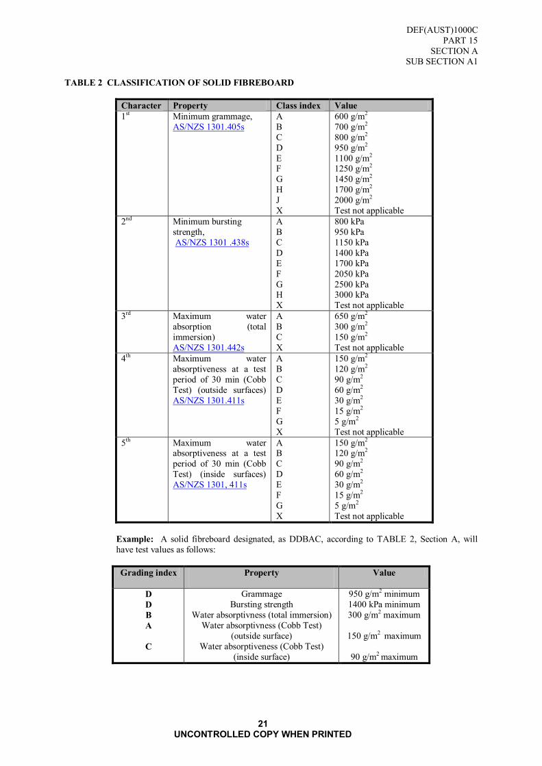
TABLE 2 CLASSIFICATION OF SOLID FIBREBOARD
Character Property Class index Value
1st Minimum grammage,
AS/NZS 1301.405s
A
B
C
D
E F
G
H
J
X
600 g/m2
700 g/m2
800 g/m2
950 g/m2
1100 g/m2 1250 g/m2
1450 g/m2
1700 g/m2
2000 g/m2
Test not applicable
2nd Minimum bursting
strength,
AS/NZS 1301 .438s
A
B
C
D
E
F
G H
X
800 kPa
950 kPa
1150 kPa
1400 kPa
1700 kPa
2050 kPa
2500 kPa 3000 kPa
Test not applicable
3rd Maximum water
absorption (total
immersion)
AS/NZS 1301.442s
A
B
C
X
650 g/m2
300 g/m2
150 g/m2
Test not applicable
4th Maximum water
absorptiveness at a test
period of 30 min (Cobb
Test) (outside surfaces)
AS/NZS 1301.411s
A
B
C
D
E
F
G
X
150 g/m2
120 g/m2
90 g/m2
60 g/m2
30 g/m2
15 g/m2
5 g/m2
Test not applicable
5th Maximum water absorptiveness at a test
period of 30 min (Cobb
Test) (inside surfaces)
AS/NZS 1301, 411s
A B
C
D
E
F
G
X
150 g/m2 120 g/m2
90 g/m2
60 g/m2
30 g/m2
15 g/m2
5 g/m2
Test not applicable
Example: A solid fibreboard designated, as DDBAC, according to TABLE 2, Section A, will
have test values as follows:
Grading index Property
Value
D
D
B
A
C
Grammage
Bursting strength
Water absorptivness (total immersion)
Water absorptivness (Cobb Test)
(outside surface)
Water absorptiveness (Cobb Test)
(inside surface)
950 g/m2 minimum
1400 kPa minimum
300 g/m2 maximum
150 g/m2 maximum
90 g/m2 maximum
DEF(AUST)1000C
PART 15
SECTION A
SUB SECTION A1
ANNEX A
22
UNCONTROLLED COPY WHEN PRINTED
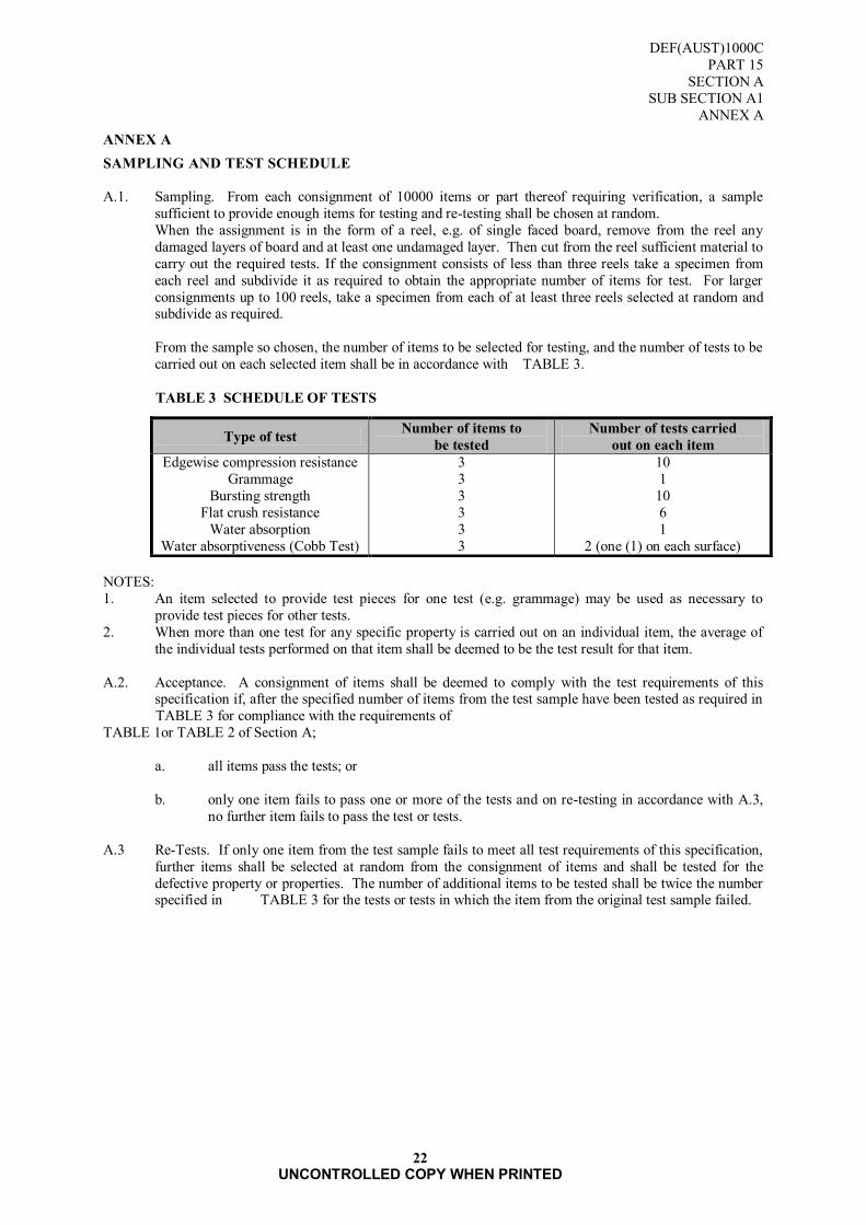
ANNEX A
SAMPLING AND TEST SCHEDULE
A.1. Sampling. From each consignment of 10000 items or part thereof requiring verification, a sample
sufficient to provide enough items for testing and re-testing shall be chosen at random.
When the assignment is in the form of a reel, e.g. of single faced board, remove from the reel any
damaged layers of board and at least one undamaged layer. Then cut from the reel sufficient material to
carry out the required tests. If the consignment consists of less than three reels take a specimen from
each reel and subdivide it as required to obtain the appropriate number of items for test. For larger
consignments up to 100 reels, take a specimen from each of at least three reels selected at random and subdivide as required.
From the sample so chosen, the number of items to be selected for testing, and the number of tests to be
carried out on each selected item shall be in accordance with TABLE 3.
TABLE 3 SCHEDULE OF TESTS
NOTES:
1. An item selected to provide test pieces for one test (e.g. grammage) may be used as necessary to
provide test pieces for other tests.
2. When more than one test for any specific property is carried out on an individual item, the average of
the individual tests performed on that item shall be deemed to be the test result for that item.
A.2. Acceptance. A consignment of items shall be deemed to comply with the test requirements of this specification if, after the specified number of items from the test sample have been tested as required in
TABLE 3 for compliance with the requirements of
TABLE 1or TABLE 2 of Section A;
a. all items pass the tests; or
b. only one item fails to pass one or more of the tests and on re-testing in accordance with A.3,
no further item fails to pass the test or tests.
A.3 Re-Tests. If only one item from the test sample fails to meet all test requirements of this specification,
further items shall be selected at random from the consignment of items and shall be tested for the
defective property or properties. The number of additional items to be tested shall be twice the number specified in TABLE 3 for the tests or tests in which the item from the original test sample failed.
Type of test Number of items to
be tested
Number of tests carried
out on each item
Edgewise compression resistance
Grammage
Bursting strength
Flat crush resistance
Water absorption
Water absorptiveness (Cobb Test)
3
3
3
3
3
3
10
1
10
6
1
2 (one (1) on each surface)

DEF(AUST)1000C
PART 15
SECTION A
SUB SECTION A2
23
UNCONTROLLED COPY WHEN PRINTED
SUB SECTION A2: FIBREBOARD CORRUGATED CLASSIFICATION
(Based on Short Column Crush Values)
1. SCOPE
1.1 This document covers corrugated fibreboard sheets and sheets fabricated into containers and
interior details such as pads, sleeves, liners, partitions, die-cut sheets etc. This specification is
applicable to single-wall, double-wall, and triple-wall corrugated fibreboard, and is suitable for
the use in the packaging of explosives and ammunition stores.
1.2 The grade classifications established in this standard are based on short column test values.
These values can be directly related to top-to bottom compression strength.
1.3 This specification does not apply to special weather resistant grades; fire retardant treated
fibreboard or solid fibreboard.
2. CLASSIFICATION
2.1 Corrugated fibreboard shall be furnished in the following types:
2.1.1 Type I -Single-wall board for use in boxes where structural rigidity and compression strength is
essential.
2.1.2 Type II -Double-wall board for use where a greater degree of structural rigidity, compression
strength and resistance to puncture is required.
2.1.3 Type III -Triple-wall board for use where maximum structural rigidity, compression strength
and resistance to puncture is required.
2.2 The types and grades of domestic corrugated fibreboard and their minimum acceptable levels of
performance are given in TABLE I, Section B.
3. APPLICABLE DOCUMENTS
3.1 Reference may be necessary to the latest issue of the following documents:
Standards Australia
AS 1199 - Sampling Procedures and TABLEs for Inspection by Attributes
AS/NZS 1301.411s - Methods of test for pulp and paper - Water absorptiveness of paper and
paperboard (Cobb test)
AS/NZS 1301.414s - Methods of test for pulp and paper - Conditioning of paper for testing
AS/NZS 1301.422s - Methods of test for pulp and paper - Determination of the pH value of aqueous
extracts of paper, board and pulp - Hot extraction method
AS/NZS 1301.426s - Methods of test for pulp and paper - Determination of thickness and apparent
bulk density or apparent sheet density
AS/NZS 1301.429s - Methods of test for pulp and paper (metric units) - Flat crush resistance of
corrugated board
AS/NZS 1301.438s - Methods of test for pulp and paper - Bursting strength of board
AS/NZS 1301.444s - Methods of test for pulp and paper - Corrugated fibreboard - Determination of
edgewise crush resistance (Unwaxed edge method) (ISO 3037:1994, MOD)
AS 2400.1 Packaging - Glossary of packaging terms
AS 3537 -Specification for general purpose corrugated fibreboard boxes and blanks

DEF(AUST)1000C
PART 15
SECTION A
SUB SECTION A2
24
UNCONTROLLED COPY WHEN PRINTED
3.2 Details of where copies of Australian Standards may be obtained from are displayed at : SAI
Global
British Standards
BS 579 - Specification for Diethyl Ether (Technical)
BS 846 - Specification for Burettes
BS 3591 - Specification for Industrial Methylated Spirits
TAPPI
T803 - Puncture and Stiffness Test of Container Board
4. TERMINOLOGY
4.1 Definitions and terminology used in connection with this specification shall be in accordance
with DEF(AUST)1000, PART 1 and AS 2400 Part 1.
5. REQUIREMENTS
5.1 Materials and Manufacture
5.1.1 Paperboard Components
Facings. The facings (linerboard) may be manufactured from any suitable wood fibre that meets the requirements of this specification.
Corrugating Medium. The corrugating medium may be manufactured from any suitable
material that meets the requirements of this specification.
5.1.2 Adhesives. Any suitable adhesive that provides a good consistent bond and allows the
combined corrugated fibreboard to meet the requirements stated in this specification may be
used.
5.2 Construction
5.2.1 Corrugated fibreboard. Shall be made with two, three, or four facings (linerboards) for single-
wall, double-wall or triple-wall respectively. Each facing shall be separated by and securely
adhered to the corrugating medium.
5.2.2 Flute Structure. The following standard flute structures shall be used as specified:
Flutes per Metre
Flute Range Mean
A 110-120 115
B 150-167 158
C 127-140 133
E 295-327 311
No more than one B-flute or E-flute may be used in any multi-wall board, except when specified by
the purchaser.
5.3 Physical Requirements
5.3.1 The combined corrugated fibreboard must comply with the requirements given in TABLE I,
Section A. All values listed are minimum requirements.

DEF(AUST)1000C
PART 15
SECTION A
SUB SECTION A2
25
UNCONTROLLED COPY WHEN PRINTED
TABLE 4 CORRUGATED FIBREBOARD, DOMESTIC
TYPE GRADE EDGE CRUSH
(lbf/in) (kN/M)
I (Single wall) 120 20 3.5
125 25 4.4
130 30 5.3
135 35 6.1
140 40 7.0 145 45 7.9
160 60 10.5
II (Double wall) 245 45 7.9
250 50 8.8
255 55 9.6
260 60 10.5
270 70 12.3
280 80 14.0
290 90 15.8
III (Triple wall) 3110 110 19.2
3135 135 23.6
3155 155 27.1
3175 175 30.6
The values specified in this TABLE are minimum values.
Test values falling below these values may be cause for rejection of the lot. (See 5.7 and 6).
5.3.2 Combined single-wall board shall meet these minimum flat crush requirements:
FLUTE kPa
A 131
B 200
C 165
5.4 Folding Requirements. Corrugated fibreboard shall show no continuous visual surface break of
the outer component ply nor any facing completely split through at the score line.
5.5 Workmanship
5.5.1 Corrugated fibreboard shall be free of tears, punctures, wrinkles, blisters, wash boarding, splices
and excessive scuffmarks, or any other types of physical damage.
5.5.2 Edges of mill run sheets shall be properly aligned so that the distance between the edges of any
two components shall not exceed 6.35 mm.
5.5.3 The amount of warp upon delivery to the customer shall not exceed 20.8 mm/meter.
5.5.4 Corrugated fibreboard shall be free of all dirt and/or oil spots or any other deposit, which will
detract from the appearance of the fibreboard.
The edges or ends of the fibreboard sheet shall not be delaminated for a distance of more than
6.35 mm.
5.5.5 Minimum caliper (thickness) of the flute structures shall be:
A-flute - 4.3 mm
B-flute - 2.3 mm
C-flute - 3.3 mm
Minimum caliper is applied to double and triple wall constructions by adding flute combinations: i.e.
CB flute = 5.6 mm minimum; AAA flute = 12.90 mm minimum. For triple wall grades 4110 and
DEF(AUST)1000C
PART 15
SECTION A
SUB SECTION A2
26
UNCONTROLLED COPY WHEN PRINTED
4135, a reduction of 5% in caliper is permitted for the sum of the flute combinations used. Flute
structure caliper does not include facings (linerboards).
To obtain caliper of the flute structure(s), first measure the thickness of the combined board structure using a vernier caliper gauge or other accurate measuring device. Then measure the
thickness of the each facing (linerboard) and subtract the thickness of the facings to obtain flute
structure(s) caliper.
Full caliper of the board shall be maintained, and shall not vary more than 0.254 mm between
the highest and lowest of ten readings. All readings must be taken at least 25.4 mm from any
score line, cut edge or printed area. Proper flute formation must be verified by visual inspection
of a clean edge cross section cut perpendicular to the flute axis and at least 152.4 mm in length.
The flute profile should exhibit a uniform curved shape without flattened tips. There shall be no
evidence of general crushing, leaning flutes, or any other defect that will cause a reduction in
caliper.
The trim or waste material shall be cleanly removed from all sheets.
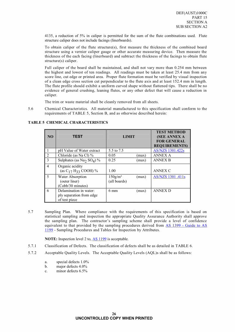
5.6 Chemical Characteristics. All material manufactured to this specification shall conform to the
requirements of TABLE 5, Section B, and as otherwise described herein:
TABLE 5 CHEMICAL CHARACTERISTICS
NO
TEST
LIMIT
TEST METHOD
(SEE ANNEX A
FOR GENERAL
REQUIREMENTS)
1 pH Value of Water extract 5.5 to 7.5 AS/NZS 1301.422s
2 Chloride (as Na Cl) % 0.05 (max) ANNEX A
3 Sulphates (as Na2 SO4) % 0.25 (max) ANNEX B
4 Organic acidity
(as C17 H33 COOH) %
1.00
ANNEX C
5 Water Absorption
(outer liner)
(Cobb/30 minutes)
150g/m²
(all boards) (max) AS/NZS 1301 .411s
6 Delamination in water:
ply separation from edge
of test piece
6 mm (max) ANNEX D
5.7 Sampling Plan. Where compliance with the requirements of this specification is based on
statistical sampling and inspection the appropriate Quality Assurance Authority shall approve
the sampling plan. The contractor‟s sampling scheme shall provide a level of confidence
equivalent to that provided by the sampling procedures derived from AS 1399 - Guide to AS
1199 - Sampling Procedures and Tables for Inspection by Attributes.
NOTE: Inspection level 2 to, AS 1199 is acceptable.
5.7.1 Classification of Defects. The classification of defects shall be as detailed in TABLE 6.
5.7.2 Acceptable Quality Levels. The Acceptable Quality Levels (AQL)s shall be as follows:
a. special defects 1.0%
b. major defects 4.0%
c. minor defects 6.5%

DEF(AUST)1000C
PART 15
SECTION A
SUB SECTION A2
27
UNCONTROLLED COPY WHEN PRINTED
TABLE 6 CLASSIFICATION OF DEFECTS
FEATURE DEFECT SPECIAL MAJOR MINOR
Materials Does not identify with
item ordered
X
Does not conform to
physical requirements
X
Fabrication Separation or
delamination of plies
X
Fluting configuration
other than specified
X
Workmanship Not clean, any mark affecting serviceability
X
Cuts, tears, holes creases,
folds
X
Sheet material not square
X
Foreign inclusions X
Dimensions not as
specified
X
Not trimmed clean or
square, ragged or
crushed edges
X
Marking Sheets or boxes not
correctly or legibly
marked
X
Packing Does not comply with
specification order
X

DEF(AUST)1000C
PART 15
SECTION A
SUB SECTION A2
28
UNCONTROLLED COPY WHEN PRINTED
Blank Page

DEF(AUST)1000C
PART 15
SECTION A
SUB SECTION A2
ANNEX A
29
UNCONTROLLED COPY WHEN PRINTED
ANNEX A
DETERMINATION OF CHLORIDE
A1. PRINCIPLE
A1. Chloride present is precipitated as silver chloride and determined turbidimetrically. If the result
exceeds the specification limit the chloride present is estimated volumetrically.
A2. REAGENTS
A2.1 Silver Nitrate Solution, 0.1 mol/L
A2.2 Ammonium Thiocyanate Solution, Standardised
, approximately 0.1 mol/L
A2.3 Nitric Acid, (d = 1.4 g/ml)
A2.4 Standard Chloride Solution, Dissolve 1.786 g of sodium chloride in water and make up to a volume
of 100 ml in a standard flask.
A2.6 Ferric Alum Indicator Solution, Dissolve 10 g of ferric alum in hot water, dilute to 100 ml and cool.
A2.7 Nitrobenzene
A3. APPARATUS
A3.1 Pipette, graduated 5 ml.
A3.2 Burette, micro 5 ml.
A3.3 Nessler tubes, 50 ml.
A4. PROCEDURE
A4.1 Take 25.0 ml extract from the pH determination (AS/NZS 1301.422s) and filter. Wash with water and
make up to a volume of 50 ml in a 50 ml Nessler tube.
A4.2 Add 1 ml nitric acid and then 5.0 ml 0.1 mol/L silver nitrate solution.
A4.3 Using a 1 ml pipette and 1 ml of working standard to a second 50 ml Nessler tube, make up to a volume
of 50 ml with water and treat as in paragraph 3.2 above. This solution represents the specification limit.
A4.4 If the turbidity of the test solution is less than that of the standard then the material conforms. If the
turbidity is equal or greater continue as follows.
A4.5 Extract a further 10 g from the material under test with 70 ml of water as in AS/NZS 1301.422s, filter
and wash, and then dilute to approximately 100 ml in a 250 ml Erlenmeyer flask.
A4.6 Add 1 ml nitric acid and then 5.0 ml 0.1 mol/L silver nitrate solution.
A4.7 Allow to stand for 10 minutes, then add 1 ml nitrobenzene and shake vigorously until the precipitate
coagulates. Add 2 ml ferric alum indicator and titrate with 0.1 mol/L ammonium thiocyanate solution
to the red end-point using a micro burette (T litre = T1).
A4.8 Take 100 ml distilled water in a 250 ml flask and treat as in paragraph A4.6 and A4.7 above (T litre =
T2).

DEF(AUST)1000C
PART 15
SECTION A
SUB SECTION A2
ANNEX A
30
UNCONTROLLED COPY WHEN PRINTED
A5. EXPRESSION OF RESULTS
The percentage of chloride as NaCl is given by:
(T2 - T1) x MAT x 0.585
Where MAT = molarity (mol/L) of ammonium thiocyanate solution.
DEF(AUST)1000C
PART 15
SECTION A
SUB SECTION A2
ANNEX B
31
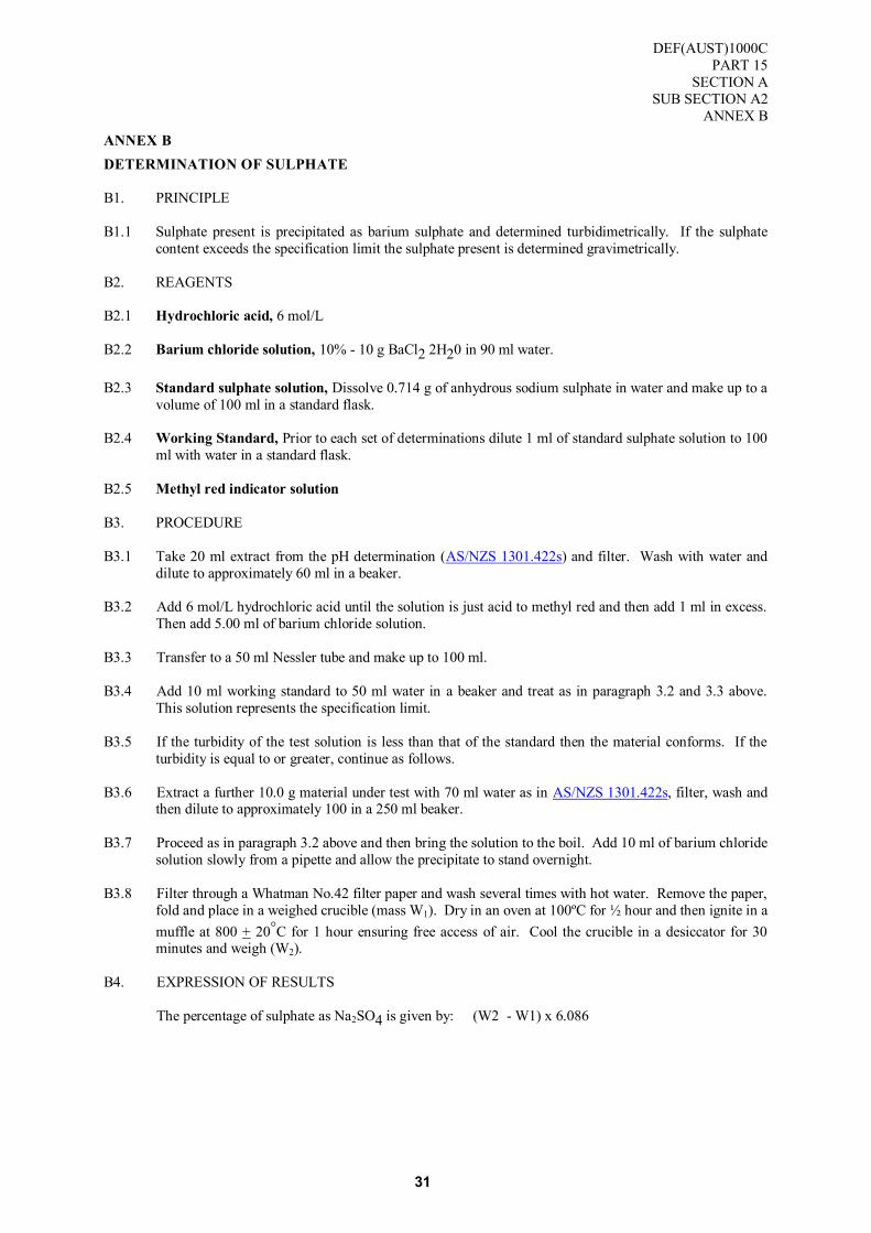
ANNEX B
DETERMINATION OF SULPHATE
B1. PRINCIPLE
B1.1 Sulphate present is precipitated as barium sulphate and determined turbidimetrically. If the sulphate
content exceeds the specification limit the sulphate present is determined gravimetrically.
B2. REAGENTS
B2.1 Hydrochloric acid, 6 mol/L
B2.2 Barium chloride solution, 10% - 10 g BaCl2 2H20 in 90 ml water.
B2.3 Standard sulphate solution, Dissolve 0.714 g of anhydrous sodium sulphate in water and make up to a
volume of 100 ml in a standard flask.
B2.4 Working Standard, Prior to each set of determinations dilute 1 ml of standard sulphate solution to 100
ml with water in a standard flask.
B2.5 Methyl red indicator solution
B3. PROCEDURE
B3.1 Take 20 ml extract from the pH determination (AS/NZS 1301.422s) and filter. Wash with water and
dilute to approximately 60 ml in a beaker.
B3.2 Add 6 mol/L hydrochloric acid until the solution is just acid to methyl red and then add 1 ml in excess.
Then add 5.00 ml of barium chloride solution.
B3.3 Transfer to a 50 ml Nessler tube and make up to 100 ml.
B3.4 Add 10 ml working standard to 50 ml water in a beaker and treat as in paragraph 3.2 and 3.3 above.
This solution represents the specification limit.
B3.5 If the turbidity of the test solution is less than that of the standard then the material conforms. If the
turbidity is equal to or greater, continue as follows.
B3.6 Extract a further 10.0 g material under test with 70 ml water as in AS/NZS 1301.422s, filter, wash and then dilute to approximately 100 in a 250 ml beaker.
B3.7 Proceed as in paragraph 3.2 above and then bring the solution to the boil. Add 10 ml of barium chloride
solution slowly from a pipette and allow the precipitate to stand overnight.
B3.8 Filter through a Whatman No.42 filter paper and wash several times with hot water. Remove the paper,
fold and place in a weighed crucible (mass W1). Dry in an oven at 100ºC for ½ hour and then ignite in a
muffle at 800 + 20°C for 1 hour ensuring free access of air. Cool the crucible in a desiccator for 30 minutes and weigh (W2).
B4. EXPRESSION OF RESULTS
The percentage of sulphate as Na2SO4 is given by: (W2 - W1) x 6.086

DEF(AUST)1000C
PART 15
SECTION A
SUB SECTION A2
ANNEX B
32
Blank Page

DEF(AUST)1000C
PART 15
SECTION A
SUB SECTION A2
ANNEX C
33
ANNEX C
DETERMINATION OF ORGANIC ACIDITY
C1. APPARATUS
C1.1 Soxhlet, apparatus of capacity approximately 100 ml.
C1.2 Burettes, complying with BS 846.
C2. REAGENTS
C2.1 Diethyl Ether, complying with BS 579.
C2.2 Sodium Hydroxide, solution 0.1 mol/L.
C2.3 Phenolphthalein, indicator solution
C2.3 Methylated Spirit, 99% (v/v) complying with BS 3591. Before using neutralise by adding 0.1 mol/L
sodium hydroxide solution using phenolphthalein as an indicator.
C3. PROCEDURE
C3.1 Cut a sample of the corrugated board into pieces approximately 10 mm square and weigh 10 + 0.1 gm
into a Soxhlet thimble, (mg).
C3.2 Using a Soxhlet apparatus of 100 ml capacity extract the sample of board with diethyl ether for 16
hours on a water-bath. The ether shall syphon from the apparatus approximately 16 times per hour.
Filter the extract through a No. 1 Whatman filter-paper. Distil the ether from the extract until the
volume is reduced to 10 ml and then add 20 ml of methylated spirit. Boil the mixture under a reflux
condenser for 10 minutes, allow to cool, add a few drops of phenolphthalein indicator solution and
titrate with 0.1 mol/L sodium hydroxide solution (V1 ml). Carry out a blank determination (without the
sample of board) following the same procedure and titrate with 0.1 mol/L sodium hydroxide (V2 ml).
Calculate the organic acidity of the sample of board as per cent .of n-Octadecanoic Acid (C17H33COOH).
C4. CALCULATION
C4.1 Per cent organic acidity as C17 H33 COOH = (V1 - V2) x 2.823
m
where
V1 = Volume of titration with the sample, in millilitres.
V2 = Volume of titration without the sample (Blank determination), in millilitres.
m = mass of sample board, in grams.

DEF(AUST)1000C
PART 15
SECTION A
SUB SECTION A2
ANNEX C
34
Blank Page

DEF(AUST)1000C
PART 15
SECTION A
SUB SECTION A2
ANNEX D
35 UNCONTROLLED COPY WHEN PRINTED
ANNEX D
TEST FOR DELAMINATION IN WATER
D1. Condition test samples as specified in AS/NZS 1301.414s.
D2. Cut a test piece 250 x 250 mm from the sample and immerse it under a minimum head of 50 mm of
water for 5 minutes. Remove the test piece from the water and flex each edge by pressure with the
thumb. Examine the test piece for separation of plies and satisfactory bonding.

DEF(AUST)1000C
PART 15
SECTION A
SUB SECTION A2
ANNEX D
36 UNCONTROLLED COPY WHEN PRINTED
Blank Page

DEF(AUST)1000C
PART 15
SECTION A
SUB SECTION A3
37 UNCONTROLLED COPY WHEN PRINTED
SUB SECTION A3: BOXES AND SHEET, FIBREBOARD, GENERAL PURPOSE
1. SCOPE
1.1 This document describes requirements of fibreboard sheet and requirements for the construction
of general purpose fibreboard boxes as outer containers. These boxes are modular to the
1100mm pallet, but are also suitable for the 1165mm pallet.
1.2 Classification. The fibreboard boxes and sheet described in this Specification shall be
classified in the following types and styles.
SHEET FIBREBOARD, CORRUGATED AND SOLID (Data Sheet No 1)
BOX TYPE 1 Box, Fibreboard, Solid, Regular Slotted (Data Sheet No 2)
BOX TYPE 2 Box, Fibreboard, Corrugated, Single Wall, Double Faced, Regular Slotted
(Data Sheet No 3)
BOX TYPE 3 Box, Fibreboard, Corrugated, Double Wall, Regular Slotted
(Data Sheet No 4)
BOX TYPE 4 Box, Fibreboard, Corrugated, Triple Wall:
Style TW1 - Regular Slotted (Data Sheet No 5)
Style TW2 - Composite Wrap Around Overlapping
Flap with Wooden Ends (Data Sheet No 6)
Style TW3 - Composite Wrap Around Meeting Flaps (Data Sheet No 7)
Style TW4 - Composite Top Overlap (Data Sheet No 8)
Style TW5 - Half Slotted Top (Data Sheet No 9)
Style TW6 - Half Slotted with Cap (Data Sheet No 10)
Style TW7 - Sleeve with Top and Bottom Caps (Data Sheet No 11)
1.3 Sizing. The recommended sizes of boxes are included in the relevant data sheets. The coding
used conforms with the modularisation of boxes to the Australian Standard Pallet. The code
system is based on external dimensions. Each size is identified by three digits e.g. 2.2.3. The
first digit (2) represents the number of boxes across one horizontal face of the pallet, the second
digit (2) the number across the other horizontal face of the pallet and the third digit (3) the
number of boxes in the height above the pallet. The maximum pallet stacking height shall be
the height of the load, which shall be 850 mm maximum, plus the pallet height. M denotes
metric series. Refer FIGURE 1 .

DEF(AUST)1000C
PART 15
SECTION A
SUB SECTION A3
38 UNCONTROLLED COPY WHEN PRINTED
FIGURE 1 THIS FIGURE ILLUSTRATES THE CODING SYSTEM AND THE METHOD OF
STACKING A PALLET. THE CODE OF THIS ILLUSTRATION IS M2.2.3
2. APPLICABLE DOCUMENTS
2.1 Reference may be necessary to the latest issue of the following documents:
Australian Department of Defence
DEF(AUST)5047 - Australian Government Ownership Symbol (Dimensions and Use)
This document is available from the sources shown inside the back cover.
(Refer Request for Documents Page)
Standards Australia
AS 1048 - International Code for Fibreboard Cases (The Selin Code)
AS 1199 - Sampling Procedures and TABLEs for Inspection by Attributes
AS/NZS 1301 - Methods of Test for Pulp & Paper (Metric Units)
AS 1489 - Sawn Boards from Radiata Pine
AS 1599 - Pressure Sensitive Adhesive Packaging Tapes
AS 2400 - (Part 1) - Glossary of Packaging Terms
AS 3537 - Fibreboard boxes, Manufacturing Practice
Details of where copies of Australian Standard may be obtained from are displayed at : SAI Global
For Defence personnel only: Standards Australia documents are available from the Defence Library
Service at the following URL:
http://library.dcb.defence.gov.au/standards/standards.nsf
2
2
3

DEF(AUST)1000C
PART 15
SECTION A
SUB SECTION A3
39 UNCONTROLLED COPY WHEN PRINTED
3. DEFINITIONS
3.1 Fibreboard. A board composed of paper and/or paperboard components laminated with an
adhesive.
3.2 Corrugated Fibreboard. A fibreboard consisting of one or more sheets of corrugated (fluted)
paper adhered to one or between several sheets of flat paper (liners). The following are types of
corrugated fibreboard:
a. Double-faced fibreboard. Fibreboard made up of one sheet of corrugated paper adhered
between two flat sheets of paper, known as single wall.
b. Double-wall fibreboard. Fibreboard made up of two sheets of corrugated paper interposed
and adhered between three flat sheets of paper, also known as twin-cushion.
c. Triple-wall. Fibreboard made up of three sheets of corrugated paper interposed and adhered between four flat sheets of paper.
TYPES OF CORRUGATED FIBREBOARD
(1) SINGLE WALL (2) DOUBLE WALL TRIPLE WALL
( (DOUBLE FACED)
TWIN CUSHION) (TRIWALL)
NOTE: The descriptions shown in brackets are commercial or trade alternatives.
3.3 Solid Fibreboard. A board composed of two or more layers of flat paper or paperboard laminated together with an adhesive.
3.4 Regular Slotted Box. A fibreboard box, with manufacturer‟s joint constructed as a complete
„sleeve‟, the top and bottom each being formed by four flaps. All flaps are the same length and
the outer flaps meet at the centre of the container. The space between the inner flaps depends
upon the relation of the length to the width of the container. A regular slotted box is equivalent
to box type 0201 in AS 1048.
3.5 Dimensions
Length - The longer dimension of the opening parallel to an edge.
Width - The shorter dimension of the opening parallel to an edge.
Depth - The dimension from the top or opening to the base.
NOTE. Where applicable these definitions are in accordance with AS 2400 Part 1. They are
repeated here for the convenience of users.
4. REQUIREMENTS
4.1 General. The technical requirements for sheet material and for each type and style of box are
contained on separate data sheets. These data sheets shall be read in conjunction with the other
requirements of this Specification.
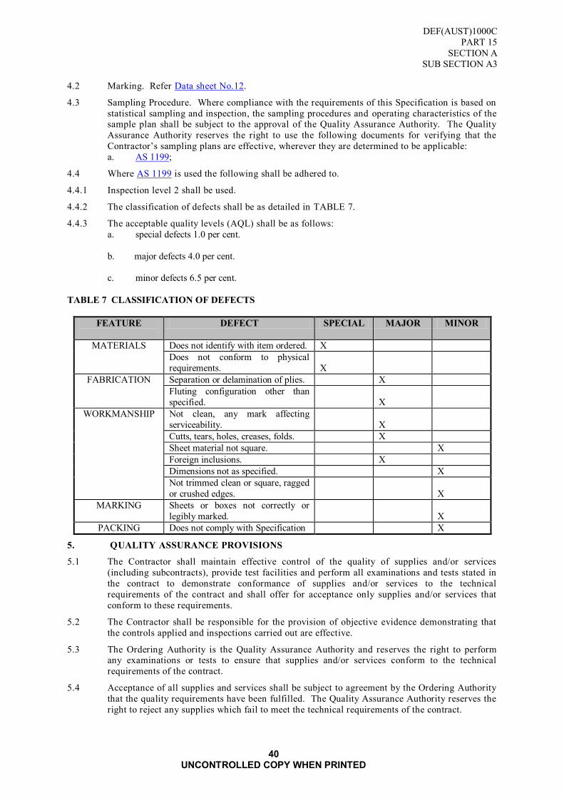
DEF(AUST)1000C
PART 15
SECTION A
SUB SECTION A3
40 UNCONTROLLED COPY WHEN PRINTED
4.2 Marking. Refer Data sheet No.12.
4.3 Sampling Procedure. Where compliance with the requirements of this Specification is based on
statistical sampling and inspection, the sampling procedures and operating characteristics of the sample plan shall be subject to the approval of the Quality Assurance Authority. The Quality
Assurance Authority reserves the right to use the following documents for verifying that the
Contractor‟s sampling plans are effective, wherever they are determined to be applicable:
a. AS 1199;
4.4 Where AS 1199 is used the following shall be adhered to.
4.4.1 Inspection level 2 shall be used.
4.4.2 The classification of defects shall be as detailed in TABLE 7.
4.4.3 The acceptable quality levels (AQL) shall be as follows:
a. special defects 1.0 per cent.
b. major defects 4.0 per cent.
c. minor defects 6.5 per cent.
TABLE 7 CLASSIFICATION OF DEFECTS
FEATURE
DEFECT SPECIAL MAJOR MINOR
MATERIALS Does not identify with item ordered. X
Does not conform to physical
requirements.
X
FABRICATION Separation or delamination of plies. X
Fluting configuration other than
specified.
X
WORKMANSHIP Not clean, any mark affecting
serviceability.
X
Cutts, tears, holes, creases, folds. X
Sheet material not square. X
Foreign inclusions. X
Dimensions not as specified. X
Not trimmed clean or square, ragged
or crushed edges.
X
MARKING Sheets or boxes not correctly or
legibly marked.
X
PACKING Does not comply with Specification X
5. QUALITY ASSURANCE PROVISIONS
5.1 The Contractor shall maintain effective control of the quality of supplies and/or services
(including subcontracts), provide test facilities and perform all examinations and tests stated in
the contract to demonstrate conformance of supplies and/or services to the technical
requirements of the contract and shall offer for acceptance only supplies and/or services that
conform to these requirements.
5.2 The Contractor shall be responsible for the provision of objective evidence demonstrating that
the controls applied and inspections carried out are effective.
5.3 The Ordering Authority is the Quality Assurance Authority and reserves the right to perform any examinations or tests to ensure that supplies and/or services conform to the technical
requirements of the contract.
5.4 Acceptance of all supplies and services shall be subject to agreement by the Ordering Authority
that the quality requirements have been fulfilled. The Quality Assurance Authority reserves the
right to reject any supplies which fail to meet the technical requirements of the contract.
DEF(AUST)1000C
PART 15
SECTION A
SUB SECTION A3
41 UNCONTROLLED COPY WHEN PRINTED
5.5 The Request for Tender and contract shall nominate the Ordering Authority, qual ity assurance
and acceptance provisions and the requirements for Contractor‟s quality control.
6. PREPARATION FOR DELIVERY
6.1 Packaging. As specified by the Ordering Authority. Unless otherwise specified the boxes shall
be packed in the manufacturer‟s commercial pack.
6.1.1 The level of the standard of packaging as defined in DEF(AUST)1000 PART 2 may be
nominated by the Ordering Authority.
6.2 Marking of Packaging.
6.2.1 Unless otherwise specified the markings shall be in accordance with relevan t sections of
DEF(AUST)1000, PART 5.

DEF(AUST)1000C
PART 15
SECTION A
SUB SECTION A3
DATA SHEET No. 1
42 UNCONTROLLED COPY WHEN PRINTED
DATA SHEET No 1
SHEET, FIBREBOARD, CORRUGATED AND SOLID
1. SCOPE
1.1 The information contained in this Data Sheet covers materials, properties and testing
requirements for corrugated and solid fibreboard sheet. This Data Sheet shall be read in
conjunction with Paragraphs 1 to 6 of this Sub section.
2. INTENDED USE
2.1 Sheet material shall be used in the manufacture of fibreboard boxes or for the manufacture of
die-cut or other package/item cushioning blocks.
3. REQUIREMENTS
3.1 Method of Numbering Board Grades. Each grade of board is numbered according to the
grammage of component materials. See “Designation” TABLE 9.
3.2 Fibreboard Solid
3.2.1 Composition. The board shall consist of layers of fillerboard and linerboards, laminated
together with a suitable water resistant adhesive to form a rigid sheet.
3.2.2 Designation. Designations in accordance with the performance criteria are listed at TABLE 9.
3.3 Fibreboard Corrugated
3.3.1 Composition. The board shall consist of one or more layers of corrugated semi-chemical or
kraft paper and flat liners, laminated together with a suitable water resistant adhesive to form a
rigid sheet.
3.3.2 Configuration. This shall be as shown in TABLE 8. Standard flutes are detailed below.
TABLE 8 CORRUGATED FIBREBOARD: FLUTE SPACING & HEIGHT
FLUTE FLUTES/METRE FLUTE HEIGHT (mm)
A 110 - 120 4.4 - 4.8
C 126 - 140 3.5 - 3.7
B 155 - 175 2.1 - 2.9
Flute height does not include the thickness of facing or liner-boards
3.3.3 Direction of Flutes. Flutes shall run perpendicular to the longest dimension of the finished
sheet.
3.3.4 Fluting. Unless otherwise specified the flute configuration for the triple wall C.A.A. that is one
outer wall shall be “C” flute.
3.4 Finish
3.4.1 The finished sheet shall be free from visible imperfections and foreign matter. The liners shall
be free from creases, wrinkles or other defects.
3.5 Scoring Properties
3.5.1 The material shall possess good scoring and bending properties. The plies shall not separate
after scoring and bending.
3.6 Dimensions
3.6.1 The material shall be to the sheet size specified by the Ordering Authority with a tolerance of
plus or minus 5 mm on all dimensions (other than thickness). The sheet shall be no more than
10 mm out of square in any direction
3.7 Physical Properties
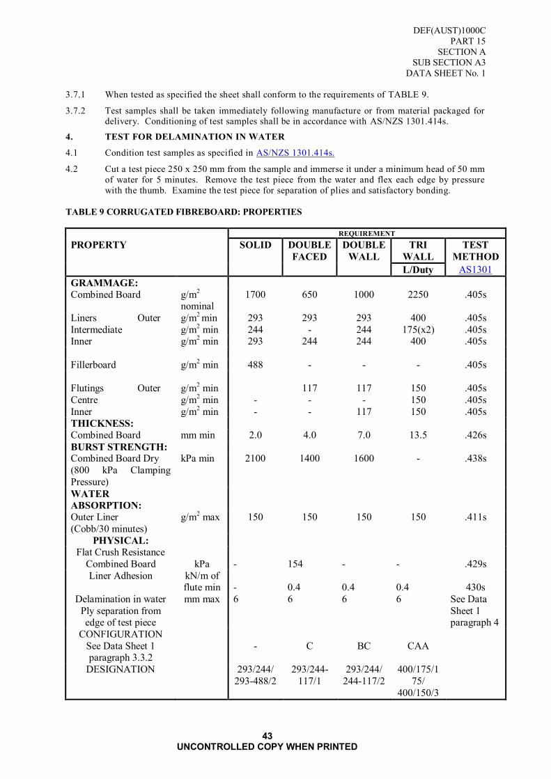
DEF(AUST)1000C
PART 15
SECTION A
SUB SECTION A3
DATA SHEET No. 1
43 UNCONTROLLED COPY WHEN PRINTED
3.7.1 When tested as specified the sheet shall conform to the requirements of TABLE 9.
3.7.2 Test samples shall be taken immediately following manufacture or from material packaged for delivery. Conditioning of test samples shall be in accordance with AS/NZS 1301.414s.
4. TEST FOR DELAMINATION IN WATER
4.1 Condition test samples as specified in AS/NZS 1301.414s.
4.2 Cut a test piece 250 x 250 mm from the sample and immerse it under a minimum head of 50 mm
of water for 5 minutes. Remove the test piece from the water and flex each edge by pressure
with the thumb. Examine the test piece for separation of plies and satisfactory bonding.
TABLE 9 CORRUGATED FIBREBOARD: PROPERTIES
REQUIREMENT
PROPERTY SOLID DOUBLE
FACED
DOUBLE
WALL
TRI
WALL
TEST
METHOD
L/Duty AS1301
GRAMMAGE:
Combined Board g/m2
nominal 1700 650 1000 2250 .405s
Liners Outer g/m2 min 293 293 293 400 .405s
Intermediate g/m2 min 244 - 244 175(x2) .405s
Inner g/m2 min 293 244 244 400 .405s
Fillerboard g/m2 min 488 - - - .405s
Flutings Outer g/m
2 min 117 117 150 .405s
Centre g/m2 min - - - 150 .405s
Inner g/m2 min - - 117 150 .405s
THICKNESS:
Combined Board mm min 2.0 4.0 7.0 13.5 .426s
BURST STRENGTH: Combined Board Dry
(800 kPa Clamping
Pressure)
kPa min 2100 1400 1600 - .438s
WATER
ABSORPTION:
Outer Liner
(Cobb/30 minutes)
g/m2 max 150 150 150 150 .411s
PHYSICAL:
Flat Crush Resistance
Combined Board
kPa
-
154
-
-
.429s
Liner Adhesion kN/m of flute min
-
0.4
0.4
0.4
430s
Delamination in water
Ply separation from edge of test piece
mm max 6 6 6 6 See Data
Sheet 1 paragraph 4
CONFIGURATION
See Data Sheet 1 paragraph 3.3.2
-
C
BC
CAA
DESIGNATION 293/244/
293-488/2
293/244-
117/1
293/244/
244-117/2
400/175/1
75/
400/150/3

DEF(AUST)1000C
PART 15
SECTION A
SUB SECTION A3
44 UNCONTROLLED COPY WHEN PRINTED
Blank Page

DEF(AUST)1000C
PART 15
SECTION A
SUB SECTION A3
45 UNCONTROLLED COPY WHEN PRINTED
DATA SHEET No 2
TYPE 1 - BOX FIBREBOARD, SOLID, REGULAR SLOTTED
1. SCOPE
1.1 The information contained in this Data Sheet covers materials, construction and size for Type 1
solid regular slotted fibreboard boxes. This Data Sheet shall be read in conjunction with
Paragraphs 1 to 6 of this Sub section.
2. DESCRIPTION
2.1 The boxes shall be solid fibreboard construction, with stitch joints and have nominal capacities
of 0.019m³ to 0.052m³.
3. INTENDED USE
3.1 The boxes are intended to be used for the packaging of a range of stores where the mass of the
box with contents does not exceed 40 kg.
4. MATERIAL
4.1 The material used shall be solid fibreboard in accordance with Data Sheet No.1.
5. CONSTRUCTION
5.1 Body. The boxes shall be one piece standard (regular slotted) fibreboard construction and shall
be cut, scored and slotted so that the assembled boxes are true to the specified dimensions.
5.2 Tolerance. The tolerance on the dimensions of the assembled box shall be plus or minus 5 mm.
5.3 Score Lines. All scoring shall be uniform and of such a depth and width to prevent surface
breaks in the board when folded at 90o along the score line parallel to the machine direction or
when folded 180o perpendicular to the machine direction.
5.3.1 Manufacturer‟s Joint. The manufacturer‟s joint shall be in accordance with AS 3537.
5.4 Stitching
5.4.1 The wire used for stitching shall be flat 2.4 mm wide by 0.5 mm thick (nominal). The crown
size of the stitch shall be not less than 12 mm. The wire shall be zinc coated (galvanised) or copper washed or similarly treated.
5.4.2 The stitches shall be placed at a 45º angle and a maximum of 25 mm apart; the 25 mm
measurement shall be from the lower tip of one stitch to the top tip of the stitch directly below.
The first and last stitch shall be placed not more than 13 mm or less than 10 mm from the end of
the lap.
FIGURE 2 TYPE 1 BOX FIBREBOARD, SOLID,REGULAR SLOTTED

DEF(AUST)1000C
PART 15
SECTION A
SUB SECTION A3
46 UNCONTROLLED COPY WHEN PRINTED
Blank Page
DEF(AUST)1000C
PART 15
SECTION A
SUB SECTION A3
DATA SHEET No. 3
47 UNCONTROLLED COPY WHEN PRINTED
DATA SHEET No 3
TYPE 2 - BOX, FIBREBOARD, CORRUGATED, SINGLE WALL
(DOUBLE FACED) REGULAR SLOTTED
1. SCOPE
1.1 The information contained in this Data Sheet covers materials, construction and sizes for a Type 2 regular slotted, corrugated, double faced fibreboard box. This Data Sheet shall be read in
conjunction with Sections 1 to 7 of this Specification.
2. DESCRIPTION
2.1 The boxes shall be of double faced corrugated fibreboard construction, with glued or stitched
joints and have nominal capacities of 0.019m³ to 0.052m³.
3. INTENDED USE
3.1 The boxes are intended to be used for the packaging of a range of stores where a greater
stackability than that of Type 1 boxes may be required. The mass of the box with contents shall not exceed 18 kg.
4. MATERIAL
4.1 The material used shall be double faced fibreboard in accordance with Data Sheet No.1.
5. CONSTRUCTION
5.1 Body. The boxes shall be one piece standard (regular slotted) fibreboard construction and shall
be cut, scored and slotted so that the assembled boxes shall be finished true to the specified
dimensions.
5.2 Tolerance. The tolerance on the dimensions of the assembled box shall be plus or minus 5 mm.
5.3 Score Lines. All scoring shall be uniform and of such depth and width to prevent surface breaks
in the board when folded 90 º º along the score line perpendicular to the flute direction or when
folded 180 º º parallel to the flute direction.
5.4 Direction of Flutes. The direction of the flutes shall run perpendicular to the score line of the
box opening.
5.5 Manufacturer‟s Joint. The joint shall be In accordance with AS 3537.
5.6 Glued Joint. Glued joints are to comply with AS 3537.
5.6.1 For glued lap joints, a good quality commercial synthetic resin type adhesive shall be used.
5.7 Stitching
5.7.1 The wire used for stitching shall be flat, 2.4 mm wide by 0.5 mm thick (nominal). The crown
size of the stitch shall be not less than 12 mm. The wire shall be zinc coated (galvanised) or copper washed or similarly treated.
5.7.2 The stitches shall be placed at a 45º angle and a maximum of 25 mm apart; the 25 mm
measurement shall be from the lower tip of one stitch to the top tip of the stitch directly below.
The first and last stitch shall be placed not more than 13 mm or less than 10 mm from the end of
the lap.
6. SIZE.
6.1 The standard size range is listed at TABLE 10.

DEF(AUST)1000C
PART 15
SECTION A
SUB SECTION A3
DATA SHEET No. 3
48 UNCONTROLLED COPY WHEN PRINTED
FIGURE 3 TYPE 2 BOX
TABLE 10 TYPE 2 - BOX FIBREBOARD, CORRUGATED, SINGLE WALL, DOUBLE FACED
SIZE
CODE
NSN
External Dimensions
Nominal mm
L x W x H
Internal Dimensions
Nominal mm
L x W x H
Capacity
M3
Item Manager
3x3x2 8115-66-086-8472 348 x 348 x 356 340 x 340 x 340 0.039 ENGSPO
2x2x1 8115-66-093-7714 494 x 494 x 502 486 x 486 x 486 0.114 ENGSPO
6x8x7 8115-66-107-1281 170 x 130 x 122 162 x 122 x 106 0.002 ENGSPO
6x8x3 8115-66-107-1282 170 x 130 x 245 162 x 122 x 229 0.004 ENGSPO
3x8x7 8115-66-107-1283 345 x 130 x 122 337 x 122 x 106 0.004 ENGSPO
3x8x3 8115-66-107-1284 345 x 130 x 245 337 x 122 x 229 0.009 ENGSPO
3x4x7 8115-66-107-1285 345 x 265 x 122 337 x 257 x 106 0.009 ENGSPO
3x4x3 8115-66-107-1286 345 x 265 x 245 337 x 257 x 229 0.019 ENGSPO
2x2x3 8115-66-131-2738 531 x 531 x 267 523 x 523 x 251 0.686 ENGSPO
3x3x3 8115-66-131-2739 351 x 351 x 267 343 x 343 x 251 0.029 5x5x4 8115-66-131-2740 205 x 205 x 190 197 x 197 x 174 0.006
2x4x3 8115-66-131-2741 531 x 261 x 267 523 x 253 x 251 0.033

DEF(AUST)1000C
PART 15
SECTION A
SUB SECTION A3
DATA SHEET No. 4
49 UNCONTROLLED COPY WHEN PRINTED
DATA SHEET No 4
TYPE 3 - BOX, FIBREBOARD, CORRUGATED, DOUBLE WALL,
REGULAR SLOTTED
1. SCOPE
1.1 The information contained in this Data Sheet covers materials, construction and sizes for a Type 3 regular slotted, corrugated, double wall fibreboard box. This Data Sheet shall be read in
conjunction with Sections 1 to 7 of this Specification.
2. DESCRIPTION
2.1 The boxes shall be of double wall corrugated fibreboard construction, with glued or stitched
joints and have nominal capacities of 0.029m³ to 1.054m³.
3. INTENDED USE
3.1 The boxes are intended to be used for the packaging of clothing or items of a similar density
where the mass of the box with contents does not exceed 35kg.
4. MATERIAL
4.1 The material used shall be double wall fibreboard in accordance with Data Sheet No.1.
5. CONSTRUCTION
5.1 Body. The boxes shall be one piece standard (regular slotted) fibreboard construction and shall
be cut, scored and slotted so that the assembled boxes shall be finished true to the specified
dimensions.
5.2 Tolerance. The tolerance on the dimensions of the assembled box shall be plus or minus 5 mm.
5.3 Score Lines. All scoring shall be uniform and of such depth and width to prevent surface breaks in the board when folded 90° along the score line perpendicular to the flute direction or when
folded 180º parallel to the flute direction.
5.4 Direction of Flutes. The direction of the flutes shall run perpendicular to the score line of the
box opening.
5.5 Manufacturer‟s Joint. The manufacturer‟s joint and the overlapped portion of the body shall be
crushed prior to gluing or stitching and shall be in accordance with AS3537.
5.6 Glued Joint
5.6.1 For glued lap joints, a good quality commercial synthetic resin type adhesive shall be used.
5.7 Stitching
5.7.1 The wire used for stitching shall be flat, 2.4 mm wide by 0.5 mm thick (nominal). The crown
size of the stitch shall be not less than 12 mm. The wire shall be zinc coated (galvanised) or copper washed or similarly treated.
5.7.2 The stitches shall be placed at a 45º angle and a maximum of 25 mm apart; the 25 mm
measurement shall be from the lower tip of one stitch to the top tip of the stitch directly below.
The first and last stitch shall be placed not more than 13 mm or less than 10 mm from the end of
the lap.
6. SIZE
6.1 The standard size range is listed at TABLE 11.
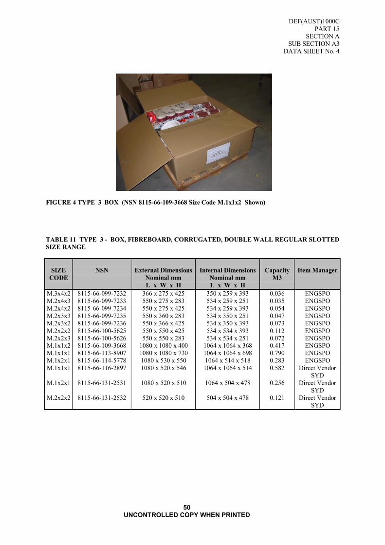
DEF(AUST)1000C
PART 15
SECTION A
SUB SECTION A3
DATA SHEET No. 4
50 UNCONTROLLED COPY WHEN PRINTED
FIGURE 4 TYPE 3 BOX (NSN 8115-66-109-3668 Size Code M.1x1x2 Shown)
TABLE 11 TYPE 3 - BOX, FIBREBOARD, CORRUGATED, DOUBLE WALL REGULAR SLOTTED
SIZE RANGE
SIZE
CODE
NSN
External Dimensions
Nominal mm
L x W x H
Internal Dimensions
Nominal mm
L x W x H
Capacity
M3
Item Manager
M.3x4x2 8115-66-099-7232 366 x 275 x 425 350 x 259 x 393 0.036 ENGSPO
M.2x4x3 8115-66-099-7233 550 x 275 x 283 534 x 259 x 251 0.035 ENGSPO
M.2x4x2 8115-66-099-7234 550 x 275 x 425 534 x 259 x 393 0.054 ENGSPO
M.2x3x3 8115-66-099-7235 550 x 360 x 283 534 x 350 x 251 0.047 ENGSPO
M.2x3x2 8115-66-099-7236 550 x 366 x 425 534 x 350 x 393 0.073 ENGSPO
M.2x2x2 8115-66-100-5625 550 x 550 x 425 534 x 534 x 393 0.112 ENGSPO
M.2x2x3 8115-66-100-5626 550 x 550 x 283 534 x 534 x 251 0.072 ENGSPO M.1x1x2 8115-66-109-3668 1080 x 1080 x 400 1064 x 1064 x 368 0.417 ENGSPO
M.1x1x1 8115-66-113-8907 1080 x 1080 x 730 1064 x 1064 x 698 0.790 ENGSPO
M.1x2x1 8115-66-114-5778 1080 x 530 x 550 1064 x 514 x 518 0.283 ENGSPO
M.1x1x1 8115-66-116-2897 1080 x 520 x 546 1064 x 1064 x 514 0.582 Direct Vendor
SYD
M.1x2x1 8115-66-131-2531 1080 x 520 x 510 1064 x 504 x 478 0.256 Direct Vendor
SYD
M.2x2x2 8115-66-131-2532 520 x 520 x 510 504 x 504 x 478 0.121 Direct Vendor
SYD

DEF(AUST)1000C
PART 15
SECTION A
SUB SECTION A3
DATA SHEET No. 5
51
UNCONTROLLED COPY WHEN PRINTED
DATA SHEET No 5
TYPE 4 STYLE TW1
BOX, FIBREBOARD, CORRUGATED, TRIPLE WALL REGULAR SLOTTED
1. SCOPE
1.1 The information contained in this Data Sheet covers materials, construction and sizes for a Type
4, Style TW1, regular slotted, corrugated, triple wall fibreboard box. This Data Sheet shall be read in conjunction with Sections 1 to 7 of this Specification.
2. DESCRIPTION
2.1 The boxes shall be of multi-wall corrugated fibreboard construction, with glued or stitched
joints and have nominal capacities of 0.100 m³ to 0.916m³.
3. INTENDED USE
3.1 These boxes are intended to be used for general purpose applications requiring high strength and
stacking abilities or when cushioning is required. These boxes are designed for repeated use.
4. MATERIAL
4.1 The material used shall be triple-wall fibreboard in accordance with Data Sheet No.1.
5. CONSTRUCTION
5.1 Body. Construction shall be in accordance with FIGURE 5. The box shall be manufactured
from one or two pieces of multi-wall corrugated fibreboard scored and slotted (slots shall have a
minimum width of 10 mm) to form a body piece having four flaps. The flaps along the longer
edge shall be the outer flaps and those along the shorter edge shall be the inner flaps. Flaps
shall not project beyond the edge of the container. Opposite flaps shall be equal in length. The
outer flaps shall not overlap when closed nor have a gap greater than 20 mm.
5.2 Tolerance. The tolerance of the dimensions of the assembled box shall be plus or minus 8 mm.
5.3 Score Lines. All scoring shall be uniform and of such depth and width to prevent surface breaks
in the board when folded 90º along the score line perpendicular to the flute direction or when
folded 180º parallel to the flute direction.
5.4 Direction of Flutes. The direction of the flutes shall run perpendicular to the score line of the
box opening.
5.5 Manufacturer‟s Joint. The manufacturer‟s joint and the overlapped portion of the body shall be
crushed prior to gluing or stitching. The lap shall be on the inside of the box and shall not be
less than 50 mm wide, in accordance with AS 3537.
5.6 Glued Joint. Glued joints are to comply with AS 3537.
5.6.1 For glued lap joints, a good quality commercial synthetic resin type adhesive shall be used.
5.7 Stitching
5.7.1 The wire used for stitching shall be flat, 2.4 mm wide by 0.5 mm thick (nominal). The crown
size of the stitch shall be not less than 12 mm. The wire shall be zinc coated (galvanised) or
copper washed or similarly treated.
5.7.2 The stitches shall be placed at a 45º angle and a maximum of 25 mm apart; the 25 mm
measurement shall be from the lower tip of one stitch to the top tip of the stitch directly below.
The first and last stitch shall be placed not more than 13 mm or less than 10 mm from the end of
the lap.
6. SIZE
6.1 The standard size range is listed at TABLE 12.

DEF(AUST)1000C
PART 15
SECTION A
SUB SECTION A3
DATA SHEET No. 5
52
UNCONTROLLED COPY WHEN PRINTED
FIGURE 5 TYPE 4 STYLE TW1 BOX
TABLE 12 TYPE 4 - STYLE TW1 BOX FIBREBOARD, CORRUGATED, TRIPLE WALL,
REGULAR SLOTTED SIZE RANGE
SIZE
CODE
NSN
External
Dimensions
Nominal mm
L x W x H
Internal Dimensions
Nominal mm
L x W x H
Capacity
M3
Item
Manager
2x2x3 8115-66-097-4019 520 x 470 x 252 492 x 442 x 196 0.042 SELMU
1x1x2 8115-66-114-9617 1072 x 1072 x 367 1044 x 1044 x 311 0.338 SELMU
1x1x1 8115-66-114-9618 1072 x 1072 x 794 1044 x 1044 x 738 0.804 SELMU
1x2x1 8115-66-114-9619 1072 x 512 x 794 1044 x 484 x 738 0.373 ENGSPO
2x2x1 8115-66-131-8334 522 x 522 x 522 494 x 484 x 464 0.110 ENGSPO

DEF(AUST)1000C
PART 15
SECTION A
SUB SECTION A3
DATA SHEET No. 6
53
UNCONTROLLED COPY WHEN PRINTED
DATA SHEET No 6
TYPE 4 STYLE TW2
BOX, FIBREBOARD, CORRUGATED, TRIPLE WALL
COMPOSITE WRAP AROUND OVERLAPPING FLAP
1. SCOPE
1.1 The information contained in this Data Sheet covers the requirements for a Type 4, Style TW2
Composite Wrap Around Overlapping Flap boxes. This Data Sheet shall be read in conjunction
with Paragraphs 1 to 6 of this Sub section.
2. DESCRIPTION
2.1 The boxes shall be of multi-wall corrugated fibreboard construction, with wooden ends which
are either nailed or stapled to the fibreboard and having nominal capacities of 0.065 m³ to
0.212 m³.
3. INTENDED USE
3.1 General purpose packaging applications where greater stacking strength is required. These
boxes have a moderate degree of water resistance and are designed for repeated use.
4. MATERIAL
4.1 Fibreboard. The material used shall be triple-wall fibreboard in accordance with Data Sheet
No.1.
4.2 Timber. Timber shall be standard grade sawn Radiata pine in accordance with AS 1489.
5. CONSTRUCTION
5.1 Body. The body shall consist of one piece of fibreboard so made as to provide five panels
forming the bottom, sides and top flap. The overlapping flap shall be not more than half the
inside width of the box and where practicable not less than 150 mm in width.
5.2 Wooden Ends. As a guide some typical ends suitable for use in composite boxes are shown at
Error! Reference source not found.. Ends without cleats shall be inserted into the box body
so that the outer face of the end is flush with the edge of the body. Cleated ends shall be
inserted so that the cleats face outwards.
5.3 Tolerance. The tolerance on the dimensions of the assembled box shall be plus or minus 8 mm.
5.4 Score Lines. All scoring shall be uniform and of such depth and width to prevent surface breaks
in the board when folded 90° along the score line perpendicular to the flute direction or when folded 180° parallel to the flute direction.
5.5 Direction of Flutes. The direction of the flutes shall run perpendicular to the score line of the
box opening.
5.6 Flap width. The flap width shall be not less than 1/3 box hight or 100 mm, whichever is the
greater.
5.7 Fabrication. The fibreboard shall be fixed to the ends of the box using either nails or staples.
5.8 Nails. Nails shall be steel, zinc coated, flat head, screw nails. They shall be commercially
available nails 30 mm in length by 2.0 mm in diameter.
5.9 Nail Spacing. The nails shall be in two rows forming a staggered pattern. The first row shall be
approximately 13 mm in from the edge of the box and the second row approximately 40 mm in
from the edge of the box. The top and bottom nails of the first row shall be placed not more than
25 mm from each corner and the top and bottom nails of the second row not more than 40 mm from each corner. All intermediate nails shall be evenly spaced, not more than 100 mm apart
(see FIGURE 14).
5.10 Reinforcing Nails. Reinforcing nails of the type shown in FIGURE 10 shall be used to
reinforce each corner of the box. The reinforcing nail shall be located as near as is practicable to

DEF(AUST)1000C
PART 15
SECTION A
SUB SECTION A3
DATA SHEET No. 6
54
UNCONTROLLED COPY WHEN PRINTED
the edge of the box, (see FIGURE 8).
5.11 Staples. The wire used for the staples shall be 1.5 mm minimum diameter. The crown width
shall be not less than 10 mm. Staple leg length shall be not less than 35 mm. The wire shall be zinc coated (galvanised) or copper washed or similar treated.
5.12 Staple Spacing. The staples shall be placed at a 45° angle and a maximum of 25 mm apart: the
25 mm measurement shall be from the lower tip of one staple to the top tip of the staple directly
below. The first and last staple shall be placed not more than 13 mm or less than 10 mm from
each corner.
FIGURE 6 STYLE TW2, FIBREBOARD, CORRUGATED, TRIPLE WALL COMPOSITE WRAP
AROUND OVERLAPPING FLAP
Figure 7 A. FRAMED WOODEN. B. FRAMED TRIPLE WALL
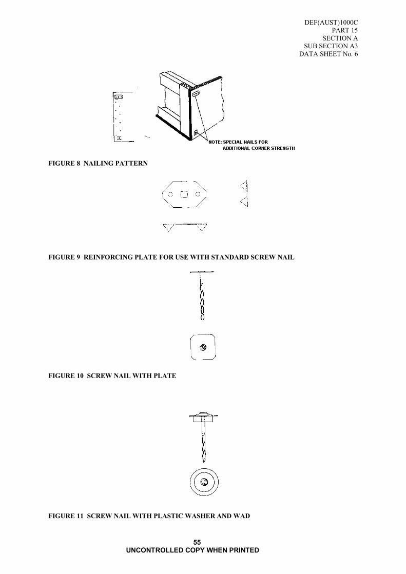
DEF(AUST)1000C
PART 15
SECTION A
SUB SECTION A3
DATA SHEET No. 6
55
UNCONTROLLED COPY WHEN PRINTED
FIGURE 8 NAILING PATTERN
FIGURE 9 REINFORCING PLATE FOR USE WITH STANDARD SCREW NAIL
FIGURE 10 SCREW NAIL WITH PLATE
FIGURE 11 SCREW NAIL WITH PLASTIC WASHER AND WAD

DEF(AUST)1000C
PART 15
SECTION A
SUB SECTION A3
DATA SHEET No. 6
56
UNCONTROLLED COPY WHEN PRINTED
Blank Page
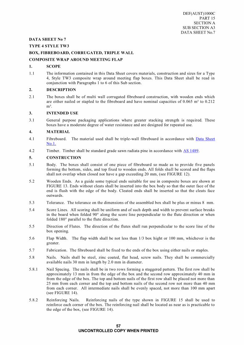
DEF(AUST)1000C
PART 15
SECTION A
SUB SECTION A3
DATA SHEET No.7
57 UNCONTROLLED COPY WHEN PRINTED
DATA SHEET No 7
TYPE 4 STYLE TW3
BOX, FIBREBOARD, CORRUGATED, TRIPLE WALL
COMPOSITE WRAP AROUND MEETING FLAP
1. SCOPE
1.1 The information contained in this Data Sheet covers materials, construction and sizes for a Type
4, Style TW3 composite wrap around meeting flap boxes. This Data Sheet shall be read in
conjunction with Paragraphs 1 to 6 of this Sub section.
2. DESCRIPTION
2.1 The boxes shall be of multi wall corrugated fibreboard construction, with wooden ends which
are either nailed or stapled to the fibreboard and have nominal capacities of 0.065 m³ to 0.212
m³.
3. INTENDED USE
3.1 General purpose packaging applications where greater stacking strength is required. These
boxes have a moderate degree of water resistance and are designed for repeated use.
4. MATERIAL
4.1 Fibreboard. The material used shall be triple-wall fibreboard in accordance with Data Sheet
No.1.
4.2 Timber. Timber shall be standard grade sawn radiata pine in accordance with AS 1489.
5. CONSTRUCTION
5.1 Body. The boxes shall consist of one piece of fibreboard so made as to provide five panels
forming the bottom, sides, and top fixed to wooden ends. All folds shall be scored and the flaps
shall not overlap when closed nor have a gap exceeding 20 mm, (see FIGURE 12).
5.2 Wooden Ends. As a guide some typical ends suitable for use in composite boxes are shown at
FIGURE 13. Ends without cleats shall be inserted into the box body so that the outer face of the
end is flush with the edge of the body. Cleated ends shall be inserted so that the cleats face
outwards.
5.3 Tolerance. The tolerance on the dimensions of the assembled box shall be plus or minus 8 mm.
5.4 Score Lines. All scoring shall be uniform and of such depth and width to prevent surface breaks
in the board when folded 90° along the score line perpendicular to the flute direction or when
folded 180° parallel to the flute direction.
5.5 Direction of Flutes. The direction of the flutes shall run perpendicular to the score line of the
box opening.
5.6 Flap Width. The flap width shall be not less than 1/3 box hight or 100 mm, whichever is the
greater.
5.7 Fabrication. The fibreboard shall be fixed to the ends of the box using either nails or staples.
5.8 Nails. Nails shall be steel, zinc coated, flat head, screw nails. They shall be commercially
available nails 30 mm in length by 2.0 mm in diameter.
5.8.1 Nail Spacing. The nails shall be in two rows forming a staggered pattern. The first row shall be
approximately 13 mm in from the edge of the box and the second row approximately 40 mm in
from the edge of the box. The top and bottom nails of the first row shall be placed not more than
25 mm from each corner and the top and bottom nails of the second row not more than 40 mm
from each corner. All intermediate nails shall be evenly spaced, not more than 100 mm apart (see FIGURE 14).
5.8.2 Reinforcing Nails. Reinforcing nails of the type shown in FIGURE 15 shall be used to
reinforce each corner of the box. The reinforcing nail shall be located as near as is practicable to
the edge of the box, (see FIGURE 14).
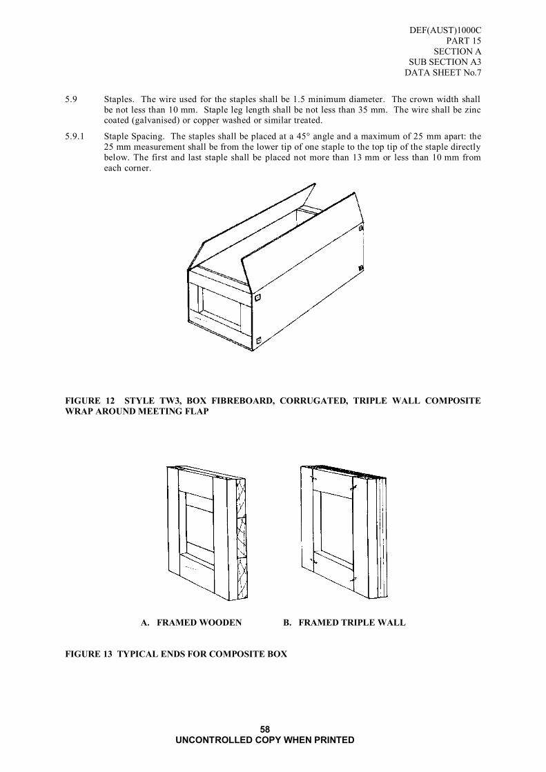
DEF(AUST)1000C
PART 15
SECTION A
SUB SECTION A3
DATA SHEET No.7
58 UNCONTROLLED COPY WHEN PRINTED
5.9 Staples. The wire used for the staples shall be 1.5 minimum diameter. The crown width shall
be not less than 10 mm. Staple leg length shall be not less than 35 mm. The wire shall be zinc coated (galvanised) or copper washed or similar treated.
5.9.1 Staple Spacing. The staples shall be placed at a 45° angle and a maximum of 25 mm apart: the
25 mm measurement shall be from the lower tip of one staple to the top tip of the staple directly
below. The first and last staple shall be placed not more than 13 mm or less than 10 mm from
each corner.
FIGURE 12 STYLE TW3, BOX FIBREBOARD, CORRUGATED, TRIPLE WALL COMPOSITE
WRAP AROUND MEETING FLAP
A. FRAMED WOODEN B. FRAMED TRIPLE WALL
FIGURE 13 TYPICAL ENDS FOR COMPOSITE BOX

DEF(AUST)1000C
PART 15
SECTION A
SUB SECTION A3
DATA SHEET No.7
59 UNCONTROLLED COPY WHEN PRINTED
FIGURE 14 NAILING PATTERN
FIGURE 15 REINFORCED PLATE FOR USE WITH STANDARD SCREW NAIL
FIGURE 16 SCREW NAIL WITH PLATE
FIGURE 17 SCREW NAIL WITH PLASTIC WASHER AND WAD

DEF(AUST)1000C
PART 15
SECTION A
SUB SECTION A3
DATA SHEET No.7
60 UNCONTROLLED COPY WHEN PRINTED
Blank Page
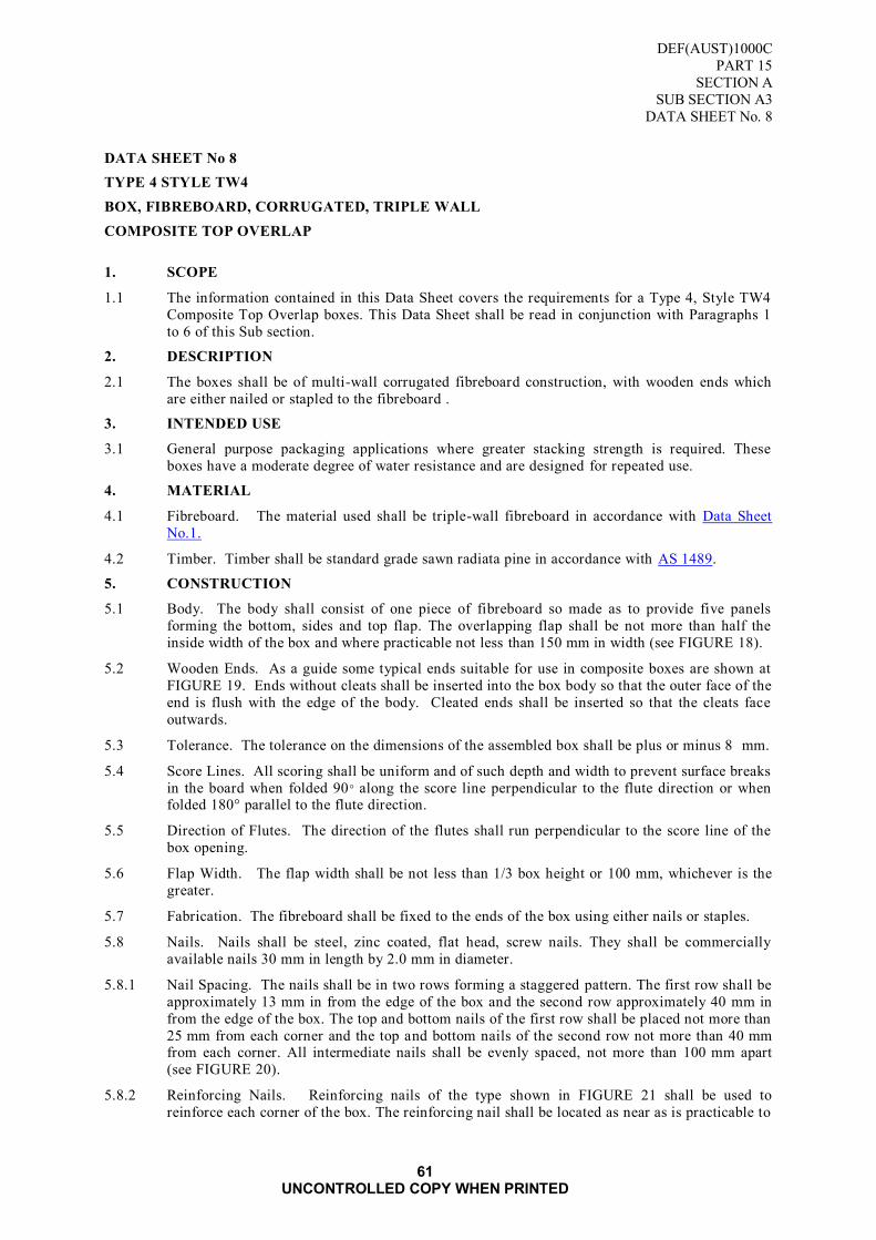
DEF(AUST)1000C
PART 15
SECTION A
SUB SECTION A3
DATA SHEET No. 8
61 UNCONTROLLED COPY WHEN PRINTED
DATA SHEET No 8
TYPE 4 STYLE TW4
BOX, FIBREBOARD, CORRUGATED, TRIPLE WALL
COMPOSITE TOP OVERLAP
1. SCOPE
1.1 The information contained in this Data Sheet covers the requirements for a Type 4, Style TW4
Composite Top Overlap boxes. This Data Sheet shall be read in conjunction with Paragraphs 1
to 6 of this Sub section.
2. DESCRIPTION
2.1 The boxes shall be of multi-wall corrugated fibreboard construction, with wooden ends which
are either nailed or stapled to the fibreboard .
3. INTENDED USE
3.1 General purpose packaging applications where greater stacking strength is required. These
boxes have a moderate degree of water resistance and are designed for repeated use.
4. MATERIAL
4.1 Fibreboard. The material used shall be triple-wall fibreboard in accordance with Data Sheet
No.1.
4.2 Timber. Timber shall be standard grade sawn radiata pine in accordance with AS 1489.
5. CONSTRUCTION
5.1 Body. The body shall consist of one piece of fibreboard so made as to provide five panels
forming the bottom, sides and top flap. The overlapping flap shall be not more than half the
inside width of the box and where practicable not less than 150 mm in width (see FIGURE 18).
5.2 Wooden Ends. As a guide some typical ends suitable for use in composite boxes are shown at
FIGURE 19. Ends without cleats shall be inserted into the box body so that the outer face of the
end is flush with the edge of the body. Cleated ends shall be inserted so that the cleats face
outwards.
5.3 Tolerance. The tolerance on the dimensions of the assembled box shall be plus or minus 8 mm.
5.4 Score Lines. All scoring shall be uniform and of such depth and width to prevent surface breaks
in the board when folded 90° along the score line perpendicular to the flute direction or when folded 180° parallel to the flute direction.
5.5 Direction of Flutes. The direction of the flutes shall run perpendicular to the score line of the
box opening.
5.6 Flap Width. The flap width shall be not less than 1/3 box height or 100 mm, whichever is the
greater.
5.7 Fabrication. The fibreboard shall be fixed to the ends of the box using either nails or staples.
5.8 Nails. Nails shall be steel, zinc coated, flat head, screw nails. They shall be commercially
available nails 30 mm in length by 2.0 mm in diameter.
5.8.1 Nail Spacing. The nails shall be in two rows forming a staggered pattern. The first row shall be
approximately 13 mm in from the edge of the box and the second row approximately 40 mm in
from the edge of the box. The top and bottom nails of the first row shall be placed not more than
25 mm from each corner and the top and bottom nails of the second row not more than 40 mm from each corner. All intermediate nails shall be evenly spaced, not more than 100 mm apart
(see FIGURE 20).
5.8.2 Reinforcing Nails. Reinforcing nails of the type shown in FIGURE 21 shall be used to
reinforce each corner of the box. The reinforcing nail shall be located as near as is practicable to
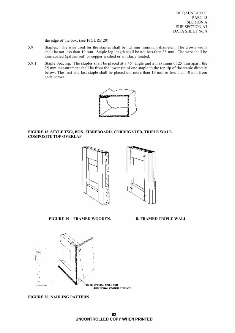
DEF(AUST)1000C
PART 15
SECTION A
SUB SECTION A3
DATA SHEET No. 8
62 UNCONTROLLED COPY WHEN PRINTED
the edge of the box, (see FIGURE 20).
5.9 Staples. The wire used for the staples shall be 1.5 mm minimum diameter. The crown width shall be not less than 10 mm. Staple leg length shall be not less than 35 mm. The wire shall be
zinc coated (galvanised) or copper washed or similarly treated.
5.9.1 Staple Spacing. The staples shall be placed at a 45° angle and a maximum of 25 mm apart: the
25 mm measurement shall be from the lower tip of one staple to the top tip of the staple directly
below. The first and last staple shall be placed not more than 13 mm or less than 10 mm from
each corner.
FIGURE 18 STYLE TW2, BOX, FIBREBOARD, CORRUGATED, TRIPLE WALL
COMPOSITE TOP OVERLAP
FIGURE 19 FRAMED WOODEN. B. FRAMED TRIPLE WALL
FIGURE 20 NAIILING PATTERN

DEF(AUST)1000C
PART 15
SECTION A
SUB SECTION A3
DATA SHEET No. 8
63 UNCONTROLLED COPY WHEN PRINTED
FIGURE 21 REINFORCING PLATE FOR USE WITH STANDARD SCREW NAIL
FIGURE 22 SCREW NAIL WITH PLATE
FIGURE 23 SCREW NAIL WITH PLASTIC WASHER AND WAD

DEF(AUST)1000C
PART 15
SECTION A
SUB SECTION A3
DATA SHEET No. 8
64 UNCONTROLLED COPY WHEN PRINTED
Blank Page

DEF(AUST)1000C
PART 15
SECTION A
SUB SECTION A3
DATA SHEET No. 9
65 UNCONTROLLED COPY WHEN PRINTED
DATA SHEET No 9
TYPE 5 STYLE TW5
BOX, FIBREBOARD, CORRUGATED, TRIPLE WALL
HALF SLOTTED TOP
1. SCOPE
1.1 The information contained in this Data Sheet covers materials, construction and sizes for a Type
5 ,Style TW5 Half Slotted Top boxes. This Data Sheet shall be read in conjunction with
Paragraphs 1 to 6 of this Sub section.
2. INTENDED USE
2.1 The boxes are intended to be used for general purpose palletised loads. These boxes have a
moderate degree of water resistance and are designed for repeated use.
3. MATERIAL
3.1 Fibreboard. The material used shall be triple-wall fibreboard in accordance with Data Sheet
No.1.
3.2 Timber. Timber shall be standard grade sawn radiata pine in accordance with AS 1489.
4. CONSTRUCTION
4.1 Body. The boxes shall be in accordance with FIGURE 24 The box shall be manufactured from
one or two pieces of triple-wall corrugated fibreboard scored and slotted (slots shall have a
minimum width of 10 mm) to form the body piece having four flaps at the top and an opening
at the bottom. The flaps along the longer edge shall be the outer flaps and those along the
shorter edge shall be the inner flaps. Flaps shall not project beyond the edge of the container.
Opposite flaps shall be equal in length. The outer flaps shall not overlap when closed nor have a gap exceeding 20 mm.
4.2 Tolerance. The tolerance on the dimensions of the assembled box shall be plus or minus 8 mm.
4.3 Score Lines. All scoring shall be uniform and of such depth and width to prevent surface breaks
in the board when folded 90° along the score line perpendicular to the flute direction or when
folded 180° parallel to the flute direction.
4.4 Direction of Flutes. The direction of the flutes shall run perpendicular to the score line of the
box opening.
4.5 Manufacturer‟s Joint. The manufacturer‟s joint and the overlapped portion of the body shall be
crushed prior to gluing or stitching. The lap shall be on the inside of the box and shall not be
less than 28 mm wide, in accordance with AS 3537.
4.6 Glued Joint. Glued joints are to comply with AS 3537.
4.6.1 For glued lap joints, a good quality commercial synthetic resin type adhesive shall be used.
4.7 Stitching. The wire used for stitching shall be flat, 2.4 mm wide by 0.5 mm thick (nominal).
The crown size of the stitch shall be not less than 10 mm. The wire shall be zinc coated
(galvanised) or copper washed or similarly treated.
4.7.1 Stitch Spacing. The stitches shall be placed at a 45 degree angle and a maximum of 25 mm
apart: the 25 mm measurement shall be from the lower tip of one stitch to the top tip of the
stitch directly below. The first and last stitch shall be placed not more than 13 mm or less than
10 mm from the end of the lap.

DEF(AUST)1000C
PART 15
SECTION A
SUB SECTION A3
DATA SHEET No. 9
66 UNCONTROLLED COPY WHEN PRINTED
FIGURE 24 STYLE TW5 BOX, FIBREBOARD, CORRUGATED, TRIPLE WALL HALF SLOTTED
TOP FOR PALLET USE

DEF(AUST)1000C
PART 15
SECTION A
SUB SECTION A3
DATA SHEET NO.10
67 UNCONTROLLED COPY WHEN PRINTED
DATA SHEET No 10 STYLE TW6
BOX, FIBREBOARD, CORRUGATED, TRIPLE WALL HALF SLOTTED WITH CAP
1. SCOPE
1.1 The information contained in this Data Sheet covers materials, construction and sizes for a Type
5, Style TW5 Half Slotted with Cap boxes. This Data Sheet shall be read in conjunction with
Paragraphs 1 to 6 of this Sub section.
2. INTENDED USE
2.1 The boxes are intended to be used for general-purpose bulk packaging. These boxes have a
moderate degree of water resistance and are designed for repeated use.
3. MATERIAL
3.1 Fibreboard. The material used shall be triple-wall fibreboard in accordance with Data Sheet
No.1.
4. CONSTRUCTION
4.1 Body. The boxes shall be in accordance with FIGURE 25. The box shall be manufactured from one or two pieces of triple-wall corrugated fibreboard scored and slotted (slots shall have a
minimum width of 10 mm) to form the body piece having four flaps. The flaps along the longer
edge shall be the outer flaps and those along the shorter edge shall be the inner flaps. Flaps shall
not project beyond the edge of the container. Opposite flaps shall be equal in length. The
outerflaps shall not overlap when closed nor have a gap exceeding 20 mm.
4.2 Cap. The cap shall be constructed as shown in FIGURE 25 and shall provide a snug fitting with
the body of the box. The depth of the cap shall not be less than 150 mm.
4.3 Tolerance. The tolerance on the dimensions of the assembled box shall be plus or minus 8 mm.
4.4 Score Lines. All scoring shall be uniform and of such depth and width to prevent surface breaks
in the board when folded 90° along the score line perpendicular to the flute direction or when
folded 180° parallel to the flute direction.
4.5 Direction of Flutes. The direction of the flutes shall run perpendicular to the score line of the box opening.
4.6 Manufacturer‟s Joint. The manufacturers joint and the overlapped portion of the body shall be
crushed prior to gluing or stitching. The lap shall be on the inside of the box and shall not be
less than 28 mm wide, in accordance with AS 3537.
4.7 Glued Joint. Glued joints are to comply with AS 3537.
4.7.1 For glued lap joints, a good quality commercial synthetic resin type adhesive shall be used.
4.8 Stitching. The wire used for stitching shall be flat, 2.4 mm wide by 0.5 mm thick (nominal).
The crown size of the stitch shall be not less than 10 mm. The wire shall be zinc coated
(galvanised) or copper washed or similarly treated.
4.8.1 Stitch Spacing. The stitches shall be placed at a 45 degree angle and a maximum of 25 mm
apart: the 25 mm measurement shall be from the lower tip of one stitch to the top tip of the stitch directly below. The first and last stitch shall be placed not more than 13 mm or less than
10 mm from the end of the lap.

DEF(AUST)1000C
PART 15
SECTION A
SUB SECTION A3
DATA SHEET NO.10
68 UNCONTROLLED COPY WHEN PRINTED
FIGURE 25 STYLE TW6 BOX, FIBREBOARD, CORRUGATED, TRIPLE WALLHALF SLOTTED
WITH CAP
DEF(AUST)1000C
PART 15
SECTION A
SUB SECTION A3
DATA SHEET NO.11
69 UNCONTROLLED COPY WHEN PRINTED
DATA SHEET No 11 STYLE TW7
BOX, FIBREBOARD, CORRUGATED, TRIPLE WALL SLEEVE WITH TOP AND BOTTOM
CAPS
1. SCOPE
1.1 The information contained in this Data Sheet covers materials, construction and sizes for a Style
TW7 Sleeve with Top and Bottom Caps. This Data Sheet shall be read in conjunction
Paragraphs 1 to 6 of this Sub section.
2. INTENDED USE
2.1 The boxes are intended to be used for general-purpose bulk packaging. These boxes have a
moderate degree of water resistance and are designed for repeated use.
3. MATERIAL
3.1 Fibreboard. The material used shall be triple-wall fibreboard in accordance with Data Sheet
No.1.
4. CONSTRUCTION
4.1 Sleeve. Construction of the sleeve shall be as shown in FIGURE 26. The sleeve shall be
manufactured from one or two pieces. If two pieces are used in the construction the
manufacturers joint shall be at diagonally opposite corners.
4.2 Caps. The caps shall be constructed as shown in FIGURE 26. and shall provide a snug fitting
with the sleeve. The depth of the cap shall not be less than 150 mm.
4.3 Tolerance. The tolerance on the dimensions of the assembled box shall be plus or minus 8 mm.
4.4 Score Lines. All scoring shall be uniform and of such depth and width to prevent surface breaks
in the board when folded 90° along the score line perpendicular to the flute direction or when
folded 180° parallel to the flute direction.
4.5 Direction of Flutes. The direction of the flutes shall run vertically on the sleeve.
4.6 Manufacturer‟s Joint. The manufacturer‟s joint and the overlapped portion of the body shall be crushed prior to gluing or stitching. The lap shall be on the inside of the box and shall not be
less than 28 mm wide, in accordance with AS 3537.
4.7 Glued Joint. Glued joints are to comply with AS 3537.
4.7.1 For glued lap joints, a good quality commercial synthetic resin type adhesive shall be used.
4.8 Stitching. The wire used for stitching shall be flat, 2.4 mm wide by 0.5 mm thick (nominal).
The crown size of the stitch shall be not less than 10 mm. The wire shall be zinc coated
(galvanised) or copper washed or similarly treated.
4.8.1 Stitch Spacing. The stitches shall be placed at a 45 degree angle and a maximum of 25 mm
apart: the 25 mm measurement shall be from the lower tip of one stitch to the top tip of the
stitch directly below. The first and last stitch shall be placed not more than 13 mm or less than
10 mm from the end of the lap.

DEF(AUST)1000C
PART 15
SECTION A
SUB SECTION A3
DATA SHEET NO.11
70 UNCONTROLLED COPY WHEN PRINTED
FIGURE 26 STYLE TW7 BOX, FIBREBOARD, CORRUGATED, TRIPLE WALL SLEEVE WITH
TOP AND BOTTOM CAPS

DEF(AUST)1000C
PART 15
SECTION A
SUB SECTION A3
DATA SHEET NO.12
71 UNCONTROLLED COPY WHEN PRINTED
DATA SHEET No 12
MINIMUM BOX MARKING REQUIREMENTS OF
FIBREBOARD BOXES - SINGLE AND DOUBLE WALL
1. SCOPE
1.1 This data sheet outlines the minimum BOX marking requirements required for single and double
wall fibreboard boxes.
2. REQUIREMENTS
2.1 Individual Boxes. Each box is to marked in black ink with the words - REUSABLE
CONTAINER - on the outer surface of flap (A) refer FIGURE 27 printed in13mm minimum to 25mm maximum height lettering, as appropriate to box size.
2.2 Each box is to marked in black ink on the outer surface of flap (B), refer FIGURE 28.
a. The name or registered trade mark of the box manufacturer.
b. The production batch identification/re-order code as stated by the manufacturer.
c. The NATO Stock Number (NSN) of the box as per applicable DATA SHEET as stated by order.
d. The number and prefix of this specification, ie. DEF(AUST)1000C, PART 15
e. Defence ownership symbol 'Broad Arrow' refer DEF(AUST)5047 f. The Recyclable Packaging Logo.
FIGURE 27 Sample Box marking
FIGURE 28 EXAMPLE OF BOX MARKING
MANUFACTURERS TRADEMARK
OR
BOX
MANUFACTURER
DETAILS
F
E
A
B,C,D
BATCH No. - As stated by
Manufacturer NSN - As specified by order
SPEC No. - DEF(AUST)1000C PART 15
Flap (A)
Flap (B)
Refer
FI
G
U
R
E
28
REUSABLE CONTAINER

DEF(AUST)1000C
PART 15
SECTION A
SUB SECTION A3
DATA SHEET NO.12
72 UNCONTROLLED COPY WHEN PRINTED
Blank Page

DEF(AUST)1000C
PART 15
SECTION B
SUB SECTION B1
73 UNCONTROLLED COPY WHEN PRINTED
SECTION B: WOOD
SUB SECTION B1: BOXES WOOD, GENERAL PURPOSE (Standard Size Range for 1100 mm
Pallet)
1. SCOPE
1.1 This document details the requirements for the construction of re-useable general-purpose
wooden boxes, other than boxes for ammunition and explosives.
1.2 Boxes, wood, general purpose, may be used for the packaging of dangerous goods provided that they conform to the specifications and pass the necessary tests as detailed in the Australian
Code for the Transport of Dangerous Goods by Road and Rail or the Technical Instructions for
the Safe Transport of Dangerous Goods by Air (ICAO) or the Dangerous Goods Regulations
(IATA) as applicable.
1.3 Classification
1.3.1 The wooden boxes described in this specification shall be boxes expanded into the following
types and classes: -
TYPE 1 - Lightweight DATA SHEET
Class 1 - Timber (Data Sheet No 1)
Class 2 - Non-Battened (Data Sheet No 2) Class 3 - Battened (6 mm timber) (Data Sheet No 3)
Class 4 - Battened (12 mm timber) (Data Sheet No 4)
TYPE 2 - Mediumweight
Class 1 - Plywood Panel Cleated (Data Sheet No 5)
Class 2 - Non-Battened (Data Sheet No 6)
Class 3 - Battened (Data Sheet No 7)
Class 4 - Battened, Two-Man Lift (Data Sheet No 8)
TYPE 3 - Heavyweight
Class 1 - Battened, Mechanical Lift (Data Sheet No 9)
Class 2 - Battened, Mechanical Lift, Heavy Duty (Data Sheet No 10)
1.4 Sizing
1.4.1 The recommended sizes of boxes are included in the relevant Data Sheets.
1.5 Coding
1.5.1 The coding used conforms to the modularisation of boxes to the 1100 mm by 1100 mm pallet as
defined by AS 4068.
1.5.2 The code system is based on external dimensions and each size is identified by a letter and 3
digits eg. M2.3.4 (see FIGURE 29) where:
a. M - denotes metric size;
b. 2 - represents the number of boxes across one horizontal face of the pallet;
c. 2 - represents the number of boxes across the other horizontal face of the pallet; and
d. 3 - represents the number of boxes in the height above the pallet.
1.5.3 The maximum pallet stacking height shall be the height of the load, which shall be 850 mm
maximum, plus the pallet height.
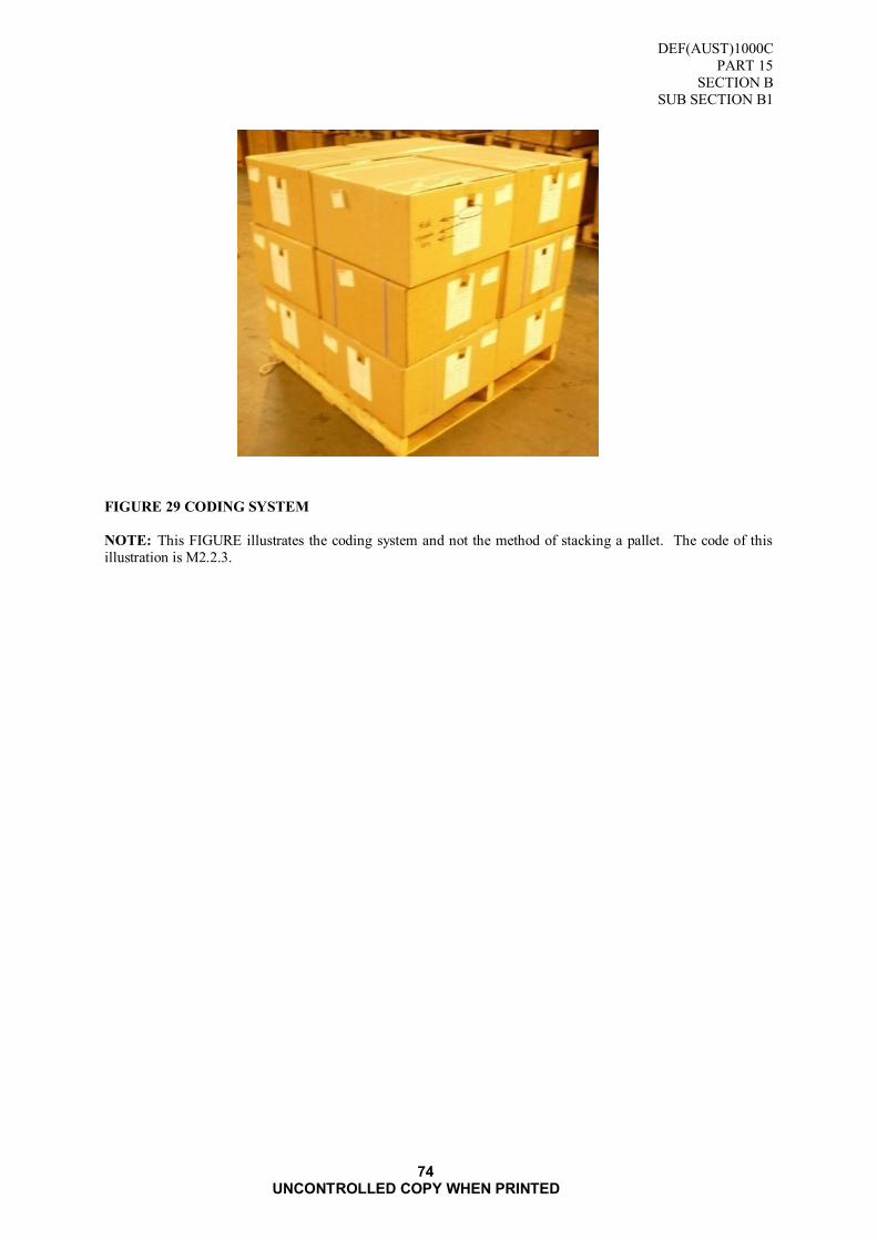
DEF(AUST)1000C
PART 15
SECTION B
SUB SECTION B1
74 UNCONTROLLED COPY WHEN PRINTED
FIGURE 29 CODING SYSTEM
NOTE: This FIGURE illustrates the coding system and not the method of stacking a pallet. The code of this
illustration is M2.2.3.

DEF(AUST)1000C
PART 15
SECTION B
SUB SECTION B1
75 UNCONTROLLED COPY WHEN PRINTED
2. APPLICABLE DOCUMENTS
2.1 Reference may be necessary to the latest issue of the following documents:
Department of Defence
DEF(AUST)5047 - Australian Government Ownership Symbol, Dimensions and Use
This document is available from the sources shown inside the back cover.
(Refer Request for Documents Page)
Standards Australia
AS 1080 - Methods of Test for Timber Part 1 - Moisture Content
AS 1199 - Sampling Procedures and Tables for Inspection by Attributes
AS 1399 - Guide to AS 1199, Sampling Procedures and Tabless for Inspection by Attributes
AS 1476 - Metric Wood Screws
AS 1489 - Sawn Boards from Radiata Pine (metric units)
AS 1604 - Preservative Treatment for Sawn Timber, Veneer and Plywood
AS 1720 - Rules for the Use of Timber in Structures (known as the SA Timber Engineering
Code)
AS 4068 - Flat Pallets for Materials Handling (1100 mm x 1100 mm suitable for use in ISO
Series 1 Freight Containers)
AS 2269 - Structural Plywood
AS 2334 - Steel Nails - Metric Series
AS 2490 - Sampling Procedures and Charts for Inspection by Variables for Percent Defective.
AS 2878 - Timbers - Classification into Strength Groupings
Details of where copies of Australian Standard may be obtained from are displayed at : SAI Global
For Defence personnel only: Standards Australia documents are available from the
Defence Library Service at the following URL:
http://library.dcb.defence.gov.au/standards/standards.nsf
3. DEFINITIONS
3.1 For the purpose of this specification the following definitions shall apply:
Assembled Box. A box with lid fitted and ready for use.
Batten. Strips of wood added to a wooden box or crate to strengthen it.
Box, Wood. A wooden container with closed sides and bottom and with open, slotted or closed
top. The sides, bottom and top may be reinforced.
Cleat. Pieces of material such as wood or metal attached to a structural body to secure strengthen or furnish a grip.
DEF(AUST)1000C
PART 15
SECTION B
SUB SECTION B1
76 UNCONTROLLED COPY WHEN PRINTED
Crate. A rigid shipping container of framed construction joined together by nails, bolts or
equivalent method of fastening. The framework may or may not be enclosed with
sheathing.
Dimension. Length -the longer dimension of the opening parallel to an edge.
Width - the shorter dimension of the opening parallel to an edge.
Depth - the dimension from the top or opening to the base.
Shooks. Cut to size components of an unassembled wooden box or crate.
Unassembled Box. An assembly of ends, sides, top and bottom components, ready to form into
an assembled box.
4. REQUIREMENTS
4.1 General
4.1.1 The technical requirements for each box are contained in separate data sheets appended to this
specification. The data sheets shall be read in conjunction with the other requirements of this
specification.
4.2 Materials
4.2.1 Timber Species. The species of timber used shall not be less than S 6 strength group
conforming to AS 1720. Suitable timbers are listed in TABLE 13.
TABLE 13 RECOMMENDED TIMBERS
RECOMMENDED TIMBERS
Hardwood Softwood
ALDER, Rose
MAPLE, Queensland
OAK, Northern Silky
PINE, Hoop
PINE Radiata
PINE, White Cypress
NOTE: Preference in selection should be given to timber that has been harvested
in a sustainable way and is recycled or reclaimed.
Timber Standard. Unless otherwise stated any timber used which complies with standards listed
in AS 1720, shall be no less than S 6 strength group, in accordance with AS MP45. The stress
grade shall be not less than F7, when graded according to the relevant structural timber grading.
Reclaimed Timber. If reclaimed timber is used, the timber shall meet all the requirements of
this specification. Timber containing bolts, nails, or screws, or containing bolt nail or screw
holes shall not be used.
Moisture Content. At the time of delivery the moisture content within any piece sold as "seasoned" shall be not less than 10 per cent or more than 18 per cent. The moisture content of
the timber shall be determined in accordance with AS 1080 Part I. In the event of dispute as to
the moisture content, it shall be determined by the oven - drying method described in Section 2
of AS 1080 Part 1.
Staining. Staining that would adversely affect the subsequent markings of the box shall not be
permitted on the external surface.
Timber Surface. Unless otherwise specified the timber shall be fine sawn on all faces.
Preservative Treatment. When specified, hardwood subject to lyctus attack shall be treated in
accordance with AS 1604 or by any method that equates to that standard. The method for
detection of susceptible sapwood is given in Appendix E of AS 1604.

DEF(AUST)1000C
PART 15
SECTION B
SUB SECTION B1
77 UNCONTROLLED COPY WHEN PRINTED
4.3 Plywood
4.3.1 Unless otherwise specified plywood shall conform to the requirements of AS 2269.
4.4 Fasteners
4.4.1 Boxes shall be constructed and assembled with T bar nails, staples, flat head processed nails or
screws.
4.4.2 Fasteners, treated against corrosion are preferred.
4.4.3 Unless otherwise specified, combinations of fasteners shall be permitted provided that the type
of fastener is consistent for each component in any one batch.
4.4.4 Sizes of fasteners are specified in the applicable data sheets.
4.5 Lifting Handles
4.5.1 Where specified, lifting handles shall be in accordance with Data Sheet No.11.
4.6 End Construction
4.6.1 Unless otherwise specified, ends shall be constructed as detailed in FIGURE 30 & FIGURE 31.
The dimensions of end cleats and fasteners shall be as specified for each style of box.
FIGURE 30 END CONSTRUCTION
FIGURE 31 END CONSTRUCTION

DEF(AUST)1000C
PART 15
SECTION B
SUB SECTION B1
78 UNCONTROLLED COPY WHEN PRINTED
4.7 Assembly
4.7.1 General. Nails, staples and screws shall be driven so that neither the head nor the crown
protrudes above the timber. Slight overdriving shall be permitted provided this does not exceed more than one-eight the thickness of the timber.
Staples. Staples shall be driven at approximately 30 degree angle to the general grain direction.
In general the requirements for nailing shall apply to stapling.
Nailing. Hand driven nails shall be driven at slightly opposing angles to each other. Nails shall
be cleanly driven from the outside except when affixing bottom bearers where the nails shall be
driven from the inside. Protruding points shall be clinched and shall not cause penetration of
any barrier material or box liner subsequently inserted into the box. Where machine driven
nails coincide with board joints additional nails shall be driven into the boards adjacent to the
joint.
Nailing Pattern. Side and bottom components shall be nailed to ends in accordance with FIGURE 32 Nailing Pattern.
(a) UP TO 100mm (b) OVER 100mm to 150mm
(c) OVER 150 mm to 200 mm
(d) OVER 200 mm to 300 mm
NOTE: W - Width of Board
FIGURE 32 NAILING PATTERN

DEF(AUST)1000C
PART 15
SECTION B
SUB SECTION B1
79 UNCONTROLLED COPY WHEN PRINTED
Screws used shall be in accordance with AS 1476.
Flat head nails used shall be in accordance with AS 2334.
4.8 Manufacturing Tolerance
4.8.1 The finished box shall conform to the size specified by the Ordering Authority with a tolerance
of + 3 mm on all dimensions.
4.8.2 Gaps between boards shall not exceed 2 mm.
4.9 Marking
4.9.1 When supplied in unassembled form each panel shall be marked with the Board Arrow Symbol
in accordance with DEF(AUST)5047.
4.9.2 When supplied in assembled form, one side and the lid panel shall be marked with the Board
Arrow Symbol in accordance with DEF(AUST)5047.
4.10 Sampling Procedure
4.10.1 Where compliance with the requirements of this specification are based on statistical sampling
and inspection, the sampling procedures and operating characteristics of the sample plan shall be subject to the approval of the Quality Assurance Authority. The Quality Assurance
Authority reserves the right to use the following documents for verifying that the Contractor's
sampling plans are effective, wherever he determines them to be applicable:
a. AS 1199;
b. AS 2490;
4.10.2 Where AS 1199 is used the following shall be adhered to.
a. Inspection Level 2 shall be used.
b. The classification of defects shall be in accordance with TABLE 14.
4.11 Acceptable Quality Levels
4.11.1 The acceptable quality levels (AQL) shall be as follows:-
a. Special defects - 0.4 per cent
b. Major defects - 1.0 per cent
c. Minor defects - 4.0 per cent
4.12 Classification of Defects
4.12.1 The following classification of defects is detailed in TABLE 14.

DEF(AUST)1000C
PART 15
SECTION B
SUB SECTION B1
80 UNCONTROLLED COPY WHEN PRINTED
TABLE 14 CLASSIFICATION OF DEFECTS
FEATURE
DEFECT SPECIAL MAJOR MINOR
Materials Species, grade, type not to specification.
Quality of material not too standard required by the specification.
Moisture content exceeds 18 per cent.
X
X
X
Construction Dimension not within tolerances.
More than specified number of pieces per
box part.
Cleats, battens, bearers incorrectly
located.
Fasteners not applied as specified.
Nailing pattern, spacing assembly not as
specified.
Gauge and length not as specified.
Assembly of box not within limits.
Handles, brackets not as specified.
X
X
X
X
X
X
X
X
Workmanship Not rigidly assembled out of square. Cleats not flush with edges.
Battens, bearers not at right angles to
boards.
Components vary dimensionally beyond
specified limits.
Space between boards exceeds 2mm.
Fasteners not clinched, protrude beyond
surface of boards
X X
X
X
X
X
Assembled box,
panel
Top panel not with box or alternatively
top panels not neatly, uniformly and
securely bundled or crated.
Quantities of boxes, panels etc not as ordered.
Boxes, panels damaged in packaging.
X
X
X
Markings Omitted, incomplete, incorrect, illegible,
or improper size. location, sequence or
method of application.
X
5. QUALITY ASSURANCE PROVISIONS
5.1 The Contractor shall maintain effective control of the quality of supplies and/or services
(including sub-contracts), provide test facilities and perform all examinations and tests stated in
the contract to demonstrate conformance of supplies and/or services to the technical
requirements of the contract and shall offer for acceptance only supplies and/or services that
conform to these requirements.
5.2 The Contractor shall be responsible for the provision of objective evidence that controls and
inspections are effective.
5.3 The Ordering Authority is the Quality Assurance Authority and reserves the right to perform
any examinations or tests in the contract to ensure that supplies and/or services conform to the
technical requirements of the contract.
5.4 Acceptance of all supplies and services shall be subject to agreement by the Ordering Authority
that the quality requirements have been fulfilled. The Quality Assurance Authority reserves the
right to reject any supplies which fail to meet the technical requirements of the contract.
5.5 The Request for tender and contract shall nominate the Ordering Authority, quality assuran ce
and acceptance provisions and the requirements for contractor's quality control.

DEF(AUST)1000C
PART 15
SECTION B
SUB SECTION B1
81 UNCONTROLLED COPY WHEN PRINTED
6. PREPARATION FOR DELIVERY
6.1 Packaging
6.1.1 Unless otherwise specified boxes shall be packaged as follows:-
a. Assembled Boxes. Boxes shall be supplied with lids packed separately. Lids shall be bundled
in multiples of ten up to a mass limit of 35 kg. The bundles shall be securely bound with flat band
steel applied two ways.
b. Unassembled Boxes. Component panels for one box shall be securely bound with flat band
steel in one bundle.
c. Assembled Panels. Component panels of ends, sides, tops and bottoms shall be made up into
separate bundles in multiples of ten up to a mass limit of 35 kg. Each bundle shall be clearly
identified by attaching securely an identification label to the top component panel of the bundle. The bundle shall be securely bound with two bands of flat band steel. The identification label shall be
marked as follows:-
(1) Type of Box as per data sheet
(2) Type of Panel
(3) Dimensions of Panel
(4) Pallet Code as per data sheet
Example: Type 1 Class 3
Ends
550 x 425 mm
M2.2.2.
6.2 Marking of packages or consignments shall be in accordance with DEF(AUST)1000, PART 5.
7. NOTES
7.1 Ordering Data
7.1.1 All purchasing documents and contracts shall specify:
a. title, number, date and amendment status of this specification;
b. type and class of box (paragraph 1.3);
c. external dimensions or size code as per Data Sheet;
d. treatment of timber (if required) (paragraph 4.2.1.7);
e. lifting handles (if required) (paragraph 4.5); and
f. quantity required.
All tender invitations, purchasing documents and contracts shall nominate the Quality Assurance
Authority, quality assurance and acceptance conditions and the requirements for contractor's quality
control.

DEF(AUST)1000C
PART 15
SECTION B
SUB SECTION B1
82 UNCONTROLLED COPY WHEN PRINTED
Blank

DEF(AUST)1000C
PART 15
SECTION B
SUB SECTION B1
DATA SHEET No.1
83 UNCONTROLLED COPY WHEN PRINTED
DATA SHEET No.1
TYPE 1 - LIGHTWEIGHT
CLASS 1 - TIMBER
1. SCOPE
1.1 This data sheet covers the technical requirements of Type 1 - Class 1 boxes and shall be read in conjunction with paragraphs 1 to 7 of this specification.
2. DESCRIPTION
2.1 A lightweight box of timber construction. The style of box shall be as depicted in FIGURE 33.
3. INTENDED USE
3.1 Used for the packaging of a range of simple light stores where the mass of box and contents
does not exceed 40 kg and the dimensions do not exceed 550 mm length or 366 mm width or
283 mm depth.
4. REQUIREMENTS
4.1 Materials List. The materials used in construction and assembly of the box shall be as specified
in TABLE 15.
TABLE 15 MATERIALS LIST
MATERIAL
REQUIREMENT (mm)
TIMBER SIZE
Boards - thickness
FASTENERS
Ends
Nails - length - diameter
Staples - leg length
- crown width
- diameter
Box Assembly
Nails - length
- diameter
Staples - leg length
- crown width
- diameter
Corrugated - length - depth
13
30 1.8
30
12
1.6
30
1.8
30
12
1.6
30 10
4.2 Manufacture
4.2.1 General. The box shall be constructed from timber panels. Boards, other than those used in the
construction of the end components, shall be joined with corrugated fasteners. Not less than
two fasteners shall be used for each joint. The fasteners shall be located approximately one-
sixth of the length in from each end of the boards.
4.2.2 Board Sizes. End boards shall be not less than 75 mm wide. All other boards shall be not less
than 50 mm wide. The maximum number of boards used in the construction of the panels shall
be as detailed in

DEF(AUST)1000C
PART 15
SECTION B
SUB SECTION B1
DATA SHEET No.1
84 UNCONTROLLED COPY WHEN PRINTED
TABLE 16 NUMBER OF BOARDS
WIDTH OF PANEL (mm) MAX NUMBER
OF BOARDS
Less than 150
Over 150 up to 200
Over 200 up to 325
Over 325 up to 460
Over 460 up to 550
1
2
3
4
5
4.2.3 End Construction. The end construction shall be as detailed in FIGURE 33. Where the width
of the box is less than 300 mm the ends may be constructed from a single board of 19 mm
nominal thickness.
4.2.4 Size. The standard size range is listed in TABLE 17.
TABLE 17 SIZE RANGE
SIZE CODE
EXTERNAL DIMENSIONS
(mm)
L x W x D
INTERNAL DIMENSIONS
(mm)
L x W x D
CAPACITY
(m3)
M2.3.4
M2.4.3
M2.4.4
M3.4.3
M3.5.4
M4.4.4
550 x 366 x 212
550 x 275 x 283
550 x 275 x 212
366 x 275 x 283
366 x 220 x 212
275 x 275 x 212
502 x 342 x 188
502 x 251 x 259
502 x 251 x 188
318 x 251 x 259
318 x 196 x 188
251 x 251 x 188
0.032
0.032
0.023
0.020
0.011
0.012
FIGURE 33 BOX STYLE

DEF(AUST)1000C
PART 15
SECTION B
SUB SECTION B1
DATA SHEET No.2
85 UNCONTROLLED COPY WHEN PRINTED
DATA SHEET No.2
TYPE 1 - LIGHTWEIGHT
CLASS 2 - NON-BATTENED
1. SCOPE
1.1 This data sheet covers the technical requirements of Type 1 - Class 2 boxes and shall be read in
conjunction with paragraphs 1 to 7 of this specification.
2. DESCRIPTION
2.1 A lightweight non-battened box of timber construction. This style of box shall be as detailed in
FIGURE 34
2.2 Used for the packaging of clothing and similar mass category stores where the mass of box and
contents does not exceed 40 kg and the dimensions do not exceed 550 mm length or 550 mm
width or 425 mm depth.
3. REQUIREMENTS
3.1 Materials List. The materials used in the construction and assembly of the box shall be as
specified in TABLE 18.
TABLE 18 MATERIALS LIST
MATERIAL
REQUIREMENT (mm)
TIMBER SIZE
Boards - thickness
Cleats -width
- thickness
FASTENERS
Ends
Nails - length
- diameter
Staples - leg length
- crown width - diameter
Box Assembly
Nails - length
- diameter
Staples - leg length
- crown width
- diameter
Corrugated - length
- depth
13
50
19
30
1.8
30
12 1.6
40
1.8
40
12
1.6
30
10
3.2 Manufacture
3.2.1 General. The box shall be constructed from timber panels. Boards, other than those used in the
construction of the end components, shall be joined with corrugated fasteners. Not less than
two fasteners shall be used for each joint. The fasteners shall be located approximately one-
sixth of the length in from each end of the boards.
3.2.2 Board Sizes. Top and bottom end boards shall be not less than 85 mm wide. All other boards
shall be not less than 50 mm wide. The maximum number of boards used in the construction of
the panels shall be as detailed in TABLE 19.

DEF(AUST)1000C
PART 15
SECTION B
SUB SECTION B1
DATA SHEET No.2
86 UNCONTROLLED COPY WHEN PRINTED
TABLE 19 NUMBER OF BOARDS
WIDTH OF PANEL (mm) MAX NUMBER OF BOARDS
Less than 125
Over 125 up to 200 Over 200 up to 325
Over 325 up to 460
Over 460 up to 550
1
2 3
4
5
3.2.3 Ends. The construction of ends shall be as detailed in paragraph 4.6 End Construction. Where
the width of the box is less than 300 mm the end cleats may be omitted provided that the
thickness of the end boards is increased by 50 per cent.
3.2.4 Size. The standard size range is listed in TABLE 20.
TABLE 20 SIZE RANGE
SIZE CODE
EXTERNAL DIMENSIONS
(mm)
L x W x D
INTERNAL DIMENSIONS
(mm)
L x W x D
CAPACITY
(m3)
M2.2.2 M2.2.3
M2.3.3
M2.4.3
550 x 550 x 425 550 x 550 x 283
550 x 366 x 283
550 x 275 x 283
488 x 526 x 401 488 x 526 x 259
488 x 342 x 259
488 x 251 x 259
0.103 0.066
0.043
0.031
FIGURE 34 BOX STYLE

DEF(AUST)1000C
PART 15
SECTION B
SUB SECTION B1
DATA SHEET No.3
87 UNCONTROLLED COPY WHEN PRINTED
DATA SHEET No. 3
TYPE 1 - LIGHTWEIGHT
CLASS 3 - BATTENED (6 mm timber)
1. SCOPE
1.1 This data sheet covers the technical requirements of Type 1 - Class 3 boxes and shall be read in conjunction with paragraphs 1 to 7 of this specification.
2. DESCRIPTION
2.1 A lightweight battened box of 6 mm timber construction. The type of box shall be as detailed in
Figure 35.
3. INTENDED USE
3.1 Used for the packaging of textile, footwear and similar mass category stores wher e the mass of
box and contents does not exceed 40 kg and the dimensions do not exceed 1100 mm length or
550 mm width or 425 mm depth.
4. REQUIREMENTS
4.1 Materials List. The materials used in construction and assembly of the box shall be as
specified in TABLE 21.
TABLE 21 MATERIALS LIST
MATERIAL
REQUIREMENT (mm)
TIMBER SIZE
Boards - thickness
Cleats - width
- thickness
Battens - width - thickness
FASTENERS
Ends
Nails - length
- diameter
Staples - leg length
- crown width
- diameter
Battens
Nails - length
- diameter Staples - leg length
- crown width
- diameter
6
50
12
50 12
30
1.8
19
12
1.6
25
1.4
19 12
1.6
Box Assembly
Nails - length
- diameter
Staples - leg length
- crown width
- diameter
30
1.8
19
12
1.6
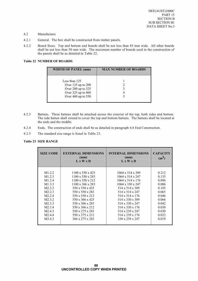
DEF(AUST)1000C
PART 15
SECTION B
SUB SECTION B1
DATA SHEET No.3
88 UNCONTROLLED COPY WHEN PRINTED
4.2 Manufacture
4.2.1 General. The box shall be constructed from timber panels.
4.2.2 Board Sizes. Top and bottom end boards shall be not less than 85 mm wide. All other boards
shall be not less than 50 mm wide. The maximum number of boards used in the construction of
the panels shall be as detailed in Table 22.
Table 22 NUMBER OF BOARDS
WIDTH OF PANEL (mm) MAX NUMBER OF BOARDS
Less than 125
Over 125 up to 200
Over 200 up to 325
Over 325 up to 460
Over 460 up to 550
1
2
3
4
5
4.2.3 Battens. Three battens shall be attached across the exterior of the top, both sides and bottom. The side batten shall extend to cover the top and bottom battens. The battens shall be located at
the ends and the middle.
4.2.4 Ends. The construction of ends shall be as detailed in paragraph 4.6 End Construction.
4.2.5 The standard size range is listed in Table 23.
Table 23 SIZE RANGE
SIZE CODE
EXTERNAL DIMENSIONS
(mm)
L x W x D
INTERNAL DIMENSIONS
(mm)
L x W x D
CAPACITY
(m3)
M1.2.2
M1.2.3 M1.2.4
M1.3.3
M2.2.2
M2.2.3
M2.2.4
M2.3.2
M2.3.3
M2.3.4
M2.4.3
M2.4.4
M3.4.3
1100 x 550 x 425
1100 x 550 x 283 1100 x 550 x 212
1100 x 366 x 283
550 x 550 x 425
550 x 550 x 283
550 x 550 x 212
550 x 366 x 425
550 x 366 x 283
550 x 366 x 212
550 x 275 x 283
550 x 275 x 212
366 x 275 x 283
1064 x 514 x 389
1064 x 514 x 247 1064 x 514 x 176
1064 x 330 x 247
514 x 514 x 389
514 x 514 x 247
514 x 514 x 176
514 x 330 x 389
514 x 330 x 247
514 x 330 x 176
514 x 239 x 247
514 x 239 x 176
330 x 239 x 247
0.212
0.135 0.096
0.086
0.103
0.065
0.046
0.066
0.042
0.030
0.030
0.022
0.019

DEF(AUST)1000C
PART 15
SECTION B
SUB SECTION B1
DATA SHEET No.4
89 UNCONTROLLED COPY WHEN PRINTED
Figure 35 BOX STYLE

DEF(AUST)1000C
PART 15
SECTION B
SUB SECTION B1
DATA SHEET No.4
90 UNCONTROLLED COPY WHEN PRINTED
Blank Page
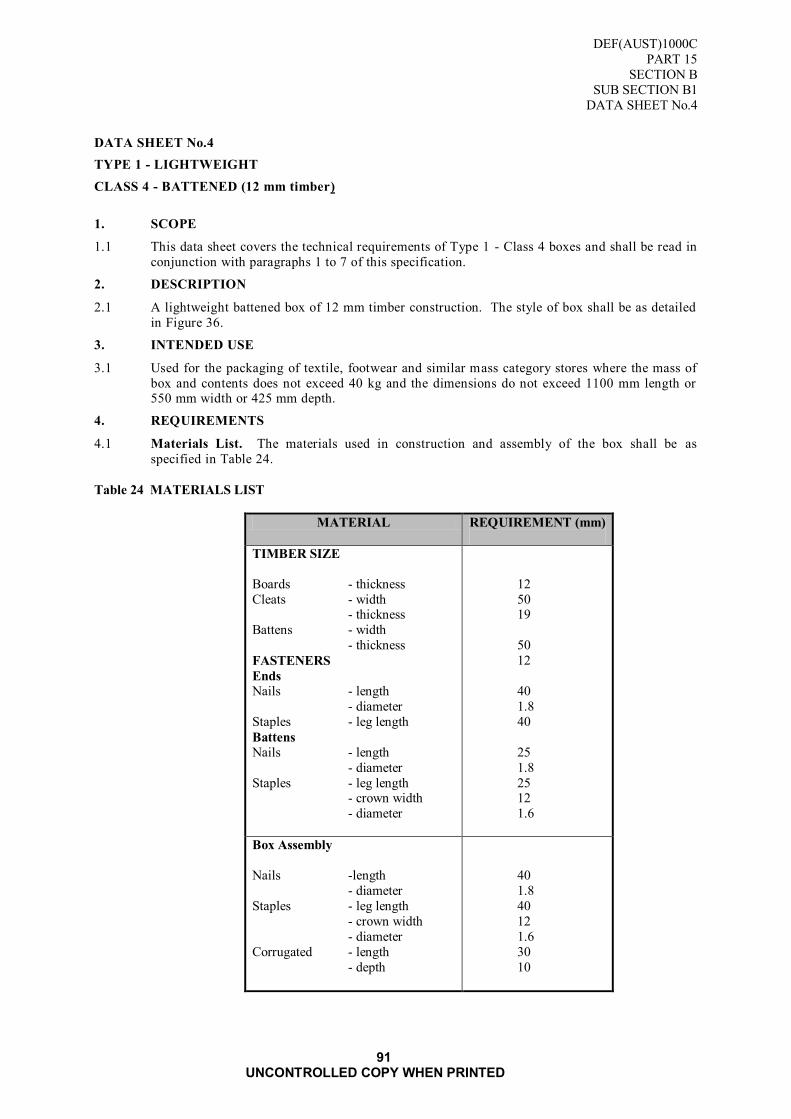
DEF(AUST)1000C
PART 15
SECTION B
SUB SECTION B1
DATA SHEET No.4
91 UNCONTROLLED COPY WHEN PRINTED
DATA SHEET No.4
TYPE 1 - LIGHTWEIGHT
CLASS 4 - BATTENED (12 mm timber)
1. SCOPE
1.1 This data sheet covers the technical requirements of Type 1 - Class 4 boxes and shall be read in
conjunction with paragraphs 1 to 7 of this specification.
2. DESCRIPTION
2.1 A lightweight battened box of 12 mm timber construction. The style of box shall be as detailed
in Figure 36.
3. INTENDED USE
3.1 Used for the packaging of textile, footwear and similar mass category stores where the mass of
box and contents does not exceed 40 kg and the dimensions do not exceed 1100 mm length or 550 mm width or 425 mm depth.
4. REQUIREMENTS
4.1 Materials List. The materials used in construction and assembly of the box shall be as
specified in Table 24.
Table 24 MATERIALS LIST
MATERIAL REQUIREMENT (mm)
TIMBER SIZE
Boards - thickness
Cleats - width - thickness
Battens - width
- thickness
FASTENERS
Ends
Nails - length
- diameter
Staples - leg length
Battens
Nails - length
- diameter
Staples - leg length - crown width
- diameter
12
50 19
50
12
40
1.8
40
25
1.8
25 12
1.6
Box Assembly
Nails -length
- diameter
Staples - leg length
- crown width
- diameter
Corrugated - length
- depth
40
1.8
40
12
1.6
30
10

DEF(AUST)1000C
PART 15
SECTION B
SUB SECTION B1
DATA SHEET No.4
92 UNCONTROLLED COPY WHEN PRINTED
4.2 Manufacture
4.2.1 General. The box shall be constructed from timber panels. Boards used in the construction of the top and bottom panels shall be joined with corrugated fasteners. Not less than two fasteners
shall be used for each joint. The fasteners shall be located approximately one-sixth of the
length in from each end of the boards. Additional fasteners shall be provided where the distance
between outer fasteners exceeds 500 mm. The additional fasteners shall be driven from the
opposite side to the outer fasteners.
4.2.2 Board Sizes. Top and bottom end boards shall be not less than 85 mm wide. All other boards
shall be not less than 50 mm wide. The maximum number of boards used in the construction of
the panels shall be as detailed in Table 25.
Table 25 NUMBER OF BOARDS
WIDTH OF PANEL (mm) MAX NUMBER OF BOARDS
Less than 125
Over 125 up to 200 Over 200 up to 325
Over 325 up to 460
Over 460 up to 550
1
2 3
4
5
4.2.3 Battens. Two battens shall be attached across the exterior of both sides, located approximately
one-sixth of the length in from each end.
4.2.4 Ends. The construction of ends shall be as detailed in paragraph 4.6 End Construction. Where
the width of the box is less than 300 mm the end cleats may be omitted provided that the
thickness of the end boards is increased by 50 per cent.
4.2.5 Size. The standard size range is listed in TABLE 26.
Table 26 SIZE RANGE
SIZE CODE
EXTERNAL DIMENSIONS
(mm)
L x W x D
INTERNAL DIMENSIONS
(mm)
L x W x D
CAPACITY
(m3)
M1.2.3
M1.2.4
M1.3.3
M2.2.2
M2.2.3
M2.2.4
M2.3.3
M2.3.4
M2.4.3 M2.4.4
M3.4.3
1100 x 550 x 283
1100 x 550 x 212
1100 x 366 x 283
550 x 550 x 425
550 x 550 x 283
550 x 550 x 212
550 x 366 x 283
550 x 366 x 212
550 x 275 x 283 550 x 275 x 212
336x 275 x 283
1052 x 502 x 259
1052 x 502 x 188
1052 x 318 x 259
502 x 502 x 401
502 x 502 x 259
502 x 502 x 188
502 x 318 x 259
502 x 318 x 188
502 x 227 x 259 502 x 227 x 188
318x 227 x 259
0.137
0.099
0.087
0.101
0.065
0.047
0.041
0.030
0.030 0.021
0.019

DEF(AUST)1000C
PART 15
SECTION B
SUB SECTION B1
DATA SHEET No.4
93 UNCONTROLLED COPY WHEN PRINTED
Figure 36 BOX STYLE

DEF(AUST)1000C
PART 15
SECTION B
SUB SECTION B1
DATA SHEET No.4
94 UNCONTROLLED COPY WHEN PRINTED
Blank Page
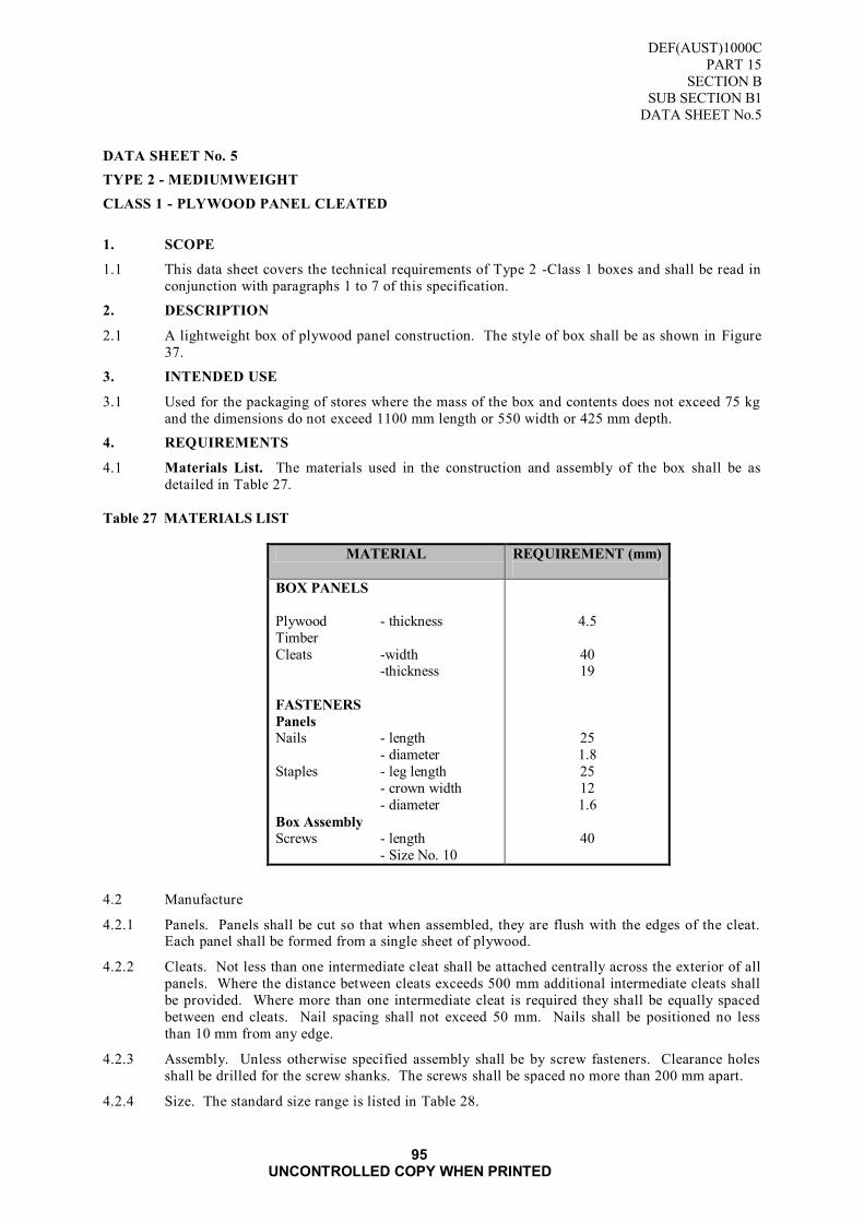
DEF(AUST)1000C
PART 15
SECTION B
SUB SECTION B1
DATA SHEET No.5
95 UNCONTROLLED COPY WHEN PRINTED
DATA SHEET No. 5
TYPE 2 - MEDIUMWEIGHT
CLASS 1 - PLYWOOD PANEL CLEATED
1. SCOPE
1.1 This data sheet covers the technical requirements of Type 2 -Class 1 boxes and shall be read in
conjunction with paragraphs 1 to 7 of this specification.
2. DESCRIPTION
2.1 A lightweight box of plywood panel construction. The style of box shall be as shown in Figure
37.
3. INTENDED USE
3.1 Used for the packaging of stores where the mass of the box and contents does not exceed 75 kg
and the dimensions do not exceed 1100 mm length or 550 width or 425 mm depth.
4. REQUIREMENTS
4.1 Materials List. The materials used in the construction and assembly of the box shall be as
detailed in Table 27.
Table 27 MATERIALS LIST
MATERIAL REQUIREMENT (mm)
BOX PANELS
Plywood - thickness
Timber
Cleats -width -thickness
FASTENERS
Panels
Nails - length
- diameter
Staples - leg length
- crown width
- diameter
Box Assembly
Screws - length
- Size No. 10
4.5
40 19
25
1.8
25
12
1.6
40
4.2 Manufacture
4.2.1 Panels. Panels shall be cut so that when assembled, they are flush with the edges of the cleat. Each panel shall be formed from a single sheet of plywood.
4.2.2 Cleats. Not less than one intermediate cleat shall be attached centrally across the exterior of all
panels. Where the distance between cleats exceeds 500 mm additional intermediate cleats shall
be provided. Where more than one intermediate cleat is required they shall be equally spaced
between end cleats. Nail spacing shall not exceed 50 mm. Nails shall be positioned no less
than 10 mm from any edge.
4.2.3 Assembly. Unless otherwise specified assembly shall be by screw fasteners. Clearance holes
shall be drilled for the screw shanks. The screws shall be spaced no more than 200 mm apart.
4.2.4 Size. The standard size range is listed in Table 28.

DEF(AUST)1000C
PART 15
SECTION B
SUB SECTION B1
DATA SHEET No.5
96 UNCONTROLLED COPY WHEN PRINTED
Table 28 SIZE RANGE
SIZE CODE
EXTERNAL DIMENSIONS
(mm)
L x W x D
INTERNAL DIMENSIONS
(mm)
L x W x D
CAPACITY
(m3)
M1.2.2
M1.2.3
M1.3.3
M2.2.2
M2.2.3
1100 x 550 x 425
1100 x 550 x 283
1100 x 366 x 283
550 x 550 x 425
550 x 550 x 283
1056 x 506 x 381
1056 x 506 x 239
1056 x 322 x 239
506 x 506 x 381
506 x 506 x 239
0.203
0.127
0.081
0.097
0.061
Figure 37 BOX STYLE

DEF(AUST)1000C
PART 15
SECTION B
SUB SECTION B1
DATA SHEET No.6
97 UNCONTROLLED COPY WHEN PRINTED
DATA SHEET No. 6
TYPE 2 - MEDIUMWEIGHT
CLASS 2 - NON-BATTENED
1. SCOPE
1.1 This data sheet covers the technical requirements of Type 2 - Class 2 boxes and shall be read in
conjunction with paragraphs 1 to 7 of this specification.
2. DESCRIPTION
2.1 A medium weight non-battened box of timber construction. The style of box shall be as detailed
in Figure 38.
3. INTENDED USE
3.1 Used for the packaging of stores where the mass of box and contents does not exceed 50 kg and
the dimensions do not exceed 1100 mm length or 550 mm width or 425 mm depth.
4. REQUIREMENTS
4.1 Materials List. The materials used in the construction and assembly of the box shall be as
specified in Table 29.
Table 29 MATERIALS LIST
MATERIAL REQUIREMENT (mm)
TIMBER SIZE
Boards - thickness
Cleats -width
- thickness
FASTENERS
Ends
Nails - length
- diameter
Staples - leg length
- crown width
- diameter
Box Assembly
Nails - length
- diameter
Staples - leg length
- crown width
- diameter Corrugated - length
- depth
19
75
19
40
1.8
40
12
1.6
45
2
40
12
1.6 28
18
4.2 Manufacture
4.2.1 General. The box shall be constructed from timber panels. Boards, other than those used in the
construction of the end components, shall be joined with corrugated fasteners. Not less than
two fasteners shall be used for each joint. The fasteners shall be located approximately one-
sixth of the length in from each end of the boards. Additional fasteners shall be provided where
the distance between outer fasteners exceeds 500 mm. The additional fasteners shall be driven
from the opposite side to the outer fasteners.
4.2.2 Board Sizes. Top and bottom end boards shall be not less than 85 mm wide. All other boards
shall be not less than 50 mm wide. The maximum number of boards used in the construction of
the panels shall be as detailed in TABLE 30..
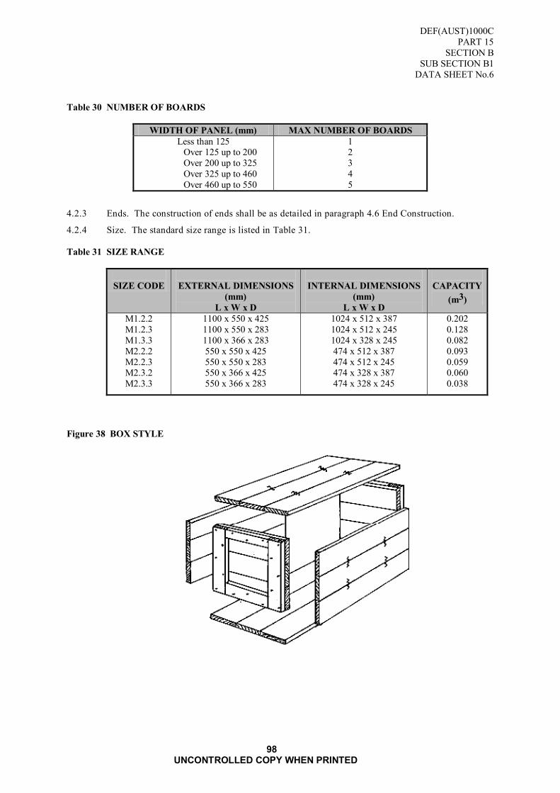
DEF(AUST)1000C
PART 15
SECTION B
SUB SECTION B1
DATA SHEET No.6
98 UNCONTROLLED COPY WHEN PRINTED
Table 30 NUMBER OF BOARDS
WIDTH OF PANEL (mm) MAX NUMBER OF BOARDS
Less than 125 Over 125 up to 200
Over 200 up to 325
Over 325 up to 460
Over 460 up to 550
1 2
3
4
5
4.2.3 Ends. The construction of ends shall be as detailed in paragraph 4.6 End Construction.
4.2.4 Size. The standard size range is listed in Table 31.
Table 31 SIZE RANGE
SIZE CODE
EXTERNAL DIMENSIONS
(mm)
L x W x D
INTERNAL DIMENSIONS
(mm)
L x W x D
CAPACITY
(m3)
M1.2.2
M1.2.3
M1.3.3
M2.2.2
M2.2.3 M2.3.2
M2.3.3
1100 x 550 x 425
1100 x 550 x 283
1100 x 366 x 283
550 x 550 x 425
550 x 550 x 283 550 x 366 x 425
550 x 366 x 283
1024 x 512 x 387
1024 x 512 x 245
1024 x 328 x 245
474 x 512 x 387
474 x 512 x 245 474 x 328 x 387
474 x 328 x 245
0.202
0.128
0.082
0.093
0.059 0.060
0.038
Figure 38 BOX STYLE

DEF(AUST)1000C
PART 15
SECTION B
SUB SECTION B1
DATA SHEET No.7
99 UNCONTROLLED COPY WHEN PRINTED
DATA SHEET No. 7
TYPE 2 - MEDIUMWEIGHT
CLASS 3 - BATTENED
1. SCOPE
1.1 This data sheet covers the technical requirements of Type 2 - Class 3 boxes and shall be read in conjunction with paragraphs 1 to 7 of this specification.
2. DESCRIPTION
2.1 A lightweight non-battened box of timber construction. This style of box shall be as detailed in
Figure 39.
3. INTENDED USE
3.1 Used for the packaging of stores where the mass of box and contents does not exceed 50 kg and
the dimensions do not exceed 550 mm length or 550 mm width or 425 mm depth.
4. REQUIREMENTS
4.1 Materials List. The materials used in the construction and assembly of the box shall be as
detailed in Table 32.
Table 32 MATERIALS LIST
MATERIAL REQUIREMENT (mm)
TIMBER SIZE
Boards - thickness
Cleats -width
-thickness
Battens - width
- thickness
FASTENERS
Ends and Battens
Nails - length
- diameter
Staples - leg length
- crown width
- diameter
Box Assembly
Nails - length - diameter
Staples - leg length
- crown width
- diameter
Corrugated – length
–depth
19
75
19
75 19
30
1.8
30
12
1.6
45 2
40
12
1.6
28
18
4.2 Manufacture
4.2.1 General. The box shall be constructed from timber panels. Boards used in the construction of
the top and bottom panels shall be joined with corrugated fasteners. Not less than two fasteners
shall be used for each joint. The fasteners shall be located approximately one-sixth of the
length in from each end of the boards. Additional fasteners shall be provided where the distance
between outer fasteners exceeds 500 mm. The additional fasteners shall be driven from the
opposite side to the outer fasteners.
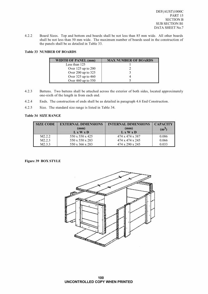
DEF(AUST)1000C
PART 15
SECTION B
SUB SECTION B1
DATA SHEET No.7
100 UNCONTROLLED COPY WHEN PRINTED
4.2.2 Board Sizes. Top and bottom end boards shall be not less than 85 mm wide. All other boards
shall be not less than 50 mm wide. The maximum number of boards used in the construction of the panels shall be as detailed in Table 33.
Table 33 NUMBER OF BOARDS
WIDTH OF PANEL (mm) MAX NUMBER OF BOARDS
Less than 125
Over 125 up to 200
Over 200 up to 325
Over 325 up to 460
Over 460 up to 550
1
2
3
4
5
4.2.3 Battens. Two battens shall be attached across the exterior of both sides, located approximately
one-sixth of the length in from each end.
4.2.4 Ends. The construction of ends shall be as detailed in paragraph 4.6 End Construction.
4.2.5 Size. The standard size range is listed in Table 34.
Table 34 SIZE RANGE
SIZE CODE EXTERNAL DIMENSIONS
(mm)
L x W x D
INTERNAL DIMENSIONS
(mm)
L x W x D
CAPACITY
(m3)
M2.2.2 M2.2.3
M2.3.3
550 x 550 x 425 550 x 550 x 283
550 x 366 x 283
474 x 474 x 387 474 x 474 x 245
474 x 290 x 245
0.086 0.066
0.033
Figure 39 BOX STYLE

DEF(AUST)1000C
PART 15
SECTION B
SUB SECTION B1
DATA SHEET No.8
101 UNCONTROLLED COPY WHEN PRINTED
DATA SHEET No. 8
TYPE 2 - MEDIUMWEIGHT
CLASS 4 - BATTENED, TWO-MAN LIFT
1. SCOPE
1.1 This data sheet covers the technical requirements of Type 2 - Class 4 boxes and shall be read in conjunction with paragraphs 1 to 7 of this specification.
2. DESCRIPTION
2.1 A mediumweight battened box of timber construction designed for two-man lift. The style of
box shall be as detailed in Figure 40.
3. INTENDED USE
3.1 Used for the packaging of stores where the mass of box and contents does not exceed 90 kg and
the dimensions do not exceed 1100 mm length or 550 mm width or 425 mm depth.
4. REQUIREMENTS
4.1 Materials List. The materials used in the construction and assembly of the box shall be as
detailed in Table 35.
Table 35 MATERIALS LIST
MATERIAL REQUIREMENT (mm)
TIMBER SIZE
Boards - thickness
Cleats -width
-thickness
Battens - width
- thickness
FASTENERS
Ends and Battens
Nails - length
- diameter
Staples - leg length
- crown width
- diameter
Box Assembly
Nails - length
- diameter
Staples - leg length - crown width
- diameter
Corrugated - length
- depth
19
75
19
75
19
40
1.8
40
12
1.6
45
2
40
12
1.6 28
18
4.2 Manufacture
4.2.1 General. The box shall be constructed from timber panels. Boards used in the construction of
the top and bottom panels shall be joined with corrugated fasteners. Not less than two fasteners
shall be used for each joint. The fasteners shall be located approximately one-sixth of the
length in from each end of the boards. Additional fasteners shall be provided where the distance
between outer fasteners exceeds 500 mm. The additional fasteners shall be driven from the
opposite side to the outer fasteners.
4.2.2 Board Sizes. Top and bottom end boards shall be not less than 85 mm wide. All other boards

DEF(AUST)1000C
PART 15
SECTION B
SUB SECTION B1
DATA SHEET No.8
102 UNCONTROLLED COPY WHEN PRINTED
shall be not less than 50 mm wide. The maximum number of boards used in the construction of
the panels shall be as detailed in Table 36.
Table 36 NUMBER OF BOARDS
WIDTH OF PANEL (mm) MAX NUMBER OF BOARDS
Less than 125
Over 125 up to 200
Over 200 up to 325
Over 325 up to 460
Over 460 up to 550
1
2
3
4
5
4.2.3 Battens. Two battens shall be attached across the exterior of both sides, located approximately
one-sixth of the length in from each end. An additional batten shall be provided where the
distance between outer battens exceeds 500 mm.
4.2.4 Ends. The construction of ends shall be as detailed in paragraph 4.6 End Construction.
4.2.5 Size. The standard size range is listed in Table 37.
Table 37 SIZE RANGE
SIZE CODE EXTERNAL DIMENSIONS
(mm)
L x W x D
INTERNAL DIMENSIONS
(mm)
L x W x D
CAPACITY
(m3)
M1.2.2 M1.2.3
M1.2.4
M1.3.3
M2.3.2
1100 x 550 x 425 1100 x 550 x 283
1100 x 550 x 212
1100 x 366 x 283
550 x 366 x 425
1024 x 474 x 387 1024 x 474 x 245
1024 x 474 x 174
1024 x 290 x 245
474 x 290 x 387
0.187 0.118
0.084
0.072
0.053
Figure 40 BOX STYLE

DEF(AUST)1000C
PART 15
SECTION B
SUB SECTION B1
DATA SHEET No.9
103 UNCONTROLLED COPY WHEN PRINTED
DATA SHEET No. 9
TYPE 3 - HEAVYWEIGHT
CLASS 1 - BATTENED, MECHANICAL LIFT
1. SCOPE
1.1 This data sheet covers the technical requirements of Type 3 - Class 1 boxes and shall be read in conjunction with paragraphs 1 to 7 of this specification.
2. DESCRIPTION
2.1 A heavyweight battened box of timber construction designed for mechanical lift. This style of
box shall be as detailed in Figure 41.
3. INTENDED USE
3.1 Used for the packaging stores where the mass of box and contents does not exceed 200 kg and
the dimensions do not exceed 1100 mm length or 550 mm width or 425 mm depth.
4. REQUIREMENTS
4.1 Materials List. The materials used in the construction and assembly of the box shall be as
detailed in Table 38.
Table 38 MATERIALS LIST
MATERIAL REQUIREMENT (mm)
TIMBER SIZE
Boards - thickness
Cleats - width
-thickness
Battens - width
- thickness
Bearers - width
- thickness
FASTENERS
Ends and Battens
Nails - length
- diameter
Staples - leg length
- crown width
- diameter
Bearers
Nails - length - diameter
Box Assembly
Nails - length
- diameter
Staples - leg length
- crown width
- diameter
Corrugated - length
- depth
19
75
19
75 19
75
95
40
2
40
12
1.6
60 2.5
45
2
40
12
1.6
28
18
4.2 Manufacture
4.2.1 General. The box shall be constructed from timber panels.
4.2.2 Board Sizes. Top and bottom end boards shall be not less than 85 mm wide. All other boards
shall be not less than 50 mm wide. The maximum number of boards used in the construction of

DEF(AUST)1000C
PART 15
SECTION B
SUB SECTION B1
DATA SHEET No.9
104 UNCONTROLLED COPY WHEN PRINTED
the panels shall be as detailed in Table 39.
Table 39 NUMBER OF BOARDS
WIDTH OF PANEL (mm) MAX NUMBER OF BOARDS
Less than 125 Over 125 up to 200
Over 200 up to 325
Over 325 up to 460
Over 460 up to 550
1 2
3
4
5
4.2.3 Battens. Two battens shall be attached across the exterior of the top and both sides. The side
battens shall extend to cover the top battens and the bearers (see Figure 41). The battens shall
be located approximately one-sixth of the length in from each end.
4.2.4 Bearers. Two bearers shall be attached across the exterior of the bottom panel located so as to
fit between the extended side battens. Bearers shall be affixed by nailing through the bottom
boards into the bearers.
4.2.5 Ends. The construction of ends shall be as detailed in paragraph 4.6 End Construction.
4.2.6 Size. The standard size range is listed in Table 40.
Table 40 SIZE RANGE
SIZE CODE EXTERNAL DIMENSIONS
(mm)
L x W x D
INTERNAL DIMENSIONS
(mm)
L x W x D
CAPACITY
(m3)
M1.2.2
M2.2.2
M2.3.2
M2.3.3
1100 x 550 x 425
550 x 550 x 425
550 x 366 x 425
550 x 366 x 283
1024 x 474 x 273
474 x 474 x 273
474 x 290 x 273
474 x 290 x 131
0.132
0.061
0.037
0.018
Figure 41 BOX STYLE

DEF(AUST)1000C
PART 15
SECTION B
SUB SECTION B1
DATA SHEET No.10
105 UNCONTROLLED COPY WHEN PRINTED
DATA SHEET No. 10
TYPE 3 - HEAVYWEIGHT
CLASS 2 - BATTENED, MECHANICAL LIFT, HEAVY DUTY
1. SCOPE
1.1 This data sheet covers the technical requirements of Type 3 - Class 2 boxes and shall be read in
conjunction with paragraphs 1 to 7 of this specification.
2. DESCRIPTION
2.1 An extra heavyweight battened box of timber construction designed for mechanical lift. This
style of box shall be as detailed in Figure 42.
3. INTENDED USE
3.1 Used for the packaging of stores where the mass of box and contents does not exceed 450 kg and the dimensions do not exceed 1100 mm length or 550 mm width or 425 mm depth.
4. REQUIREMENTS
4.1 Materials List. The materials used in the construction and assembly of the box shall be as
detailed in Table 41.
Table 41 MATERIALS LIST
MATERIAL REQUIREMENT (mm)
TIMBER SIZE
Boards - thickness
Cleats - width
-thickness Battens - width
- thickness
Bearers - width
- thickness
FASTENERS
Ends and Battens
Nails - length
- diameter
Staples - leg length
- crown width
- diameter
Bearers Nails - length
- diameter
Box Assembly
Nails - length
- diameter
Staples - leg length
- crown width
- diameter
19
95
19 95
19
75
95
40
2.5
40
12
1.6
60
2.5
50
2.5
50
12
1.6
4.2 Manufacture
4.2.1 General. The box shall be constructed from timber panels.
4.2.2 Board Sizes. Top and bottom end boards shall be not less than 85 mm wide. All other boards

DEF(AUST)1000C
PART 15
SECTION B
SUB SECTION B1
DATA SHEET No.10
106 UNCONTROLLED COPY WHEN PRINTED
shall be not less than 50 mm wide. The maximum number of boards used in the construction of
the panels shall be as detailed in the following table.
Table 42 NUMBER OF BOARDS
WIDTH OF PANEL (mm) MAX NUMBER OF BOARDS
Less than 125
Over 125 up to 200
Over 200 up to 325
Over 325 up to 460
Over 460 up to 550
1
2
3
4
5
4.2.3 Battens. Two battens shall be attached across the exterior of the top and both sides. Th side
battens shall extend to cover the top battens and the bearers (see Figure 42). The battens shall
be located approximately one-sixth of the length in from each end. An additional batten shall be
provided where the distance between outer battens exceeds 500 mm.
4.2.4 Bearers. Two bearers shall be attached across the exterior of the bottom panel, located so as to
fit between the extended side battens. An additional bearer shall be provided where the distance
between outer bearers exceeds 500 mm. Bearers shall be affixed by nailing through the bottom boards into the bearers.
4.2.5 Ends. The construction of ends shall be as detailed in paragraph 4.6 End Construction.
4.2.6 Size. The standard size range is listed in Table 43.
Table 43 SIZE RANGE
SIZE CODE EXTERNAL DIMENSIONS
(mm)
L x W x D
INTERNAL DIMENSIONS
(mm)
L x W x D
CAPACITY
(m3)
M1.2.2
M2.2.2
M2.3.2
1100 x 550 x 425
550 x 550 x 425
550 x 366 x 425
1024 x 474 x 273
474 x 474 x 273
474 x 290 x 273
0.132
0.061
0.037
Figure 42 BOX STYLE

DEF(AUST)1000C
PART 15
SECTION B
SUB SECTION B1
DATA SHEET No.11
107 UNCONTROLLED COPY WHEN PRINTED
DATA SHEET No. 11
LIFTING HANDLES
1. GENERAL
1.1 This data sheet describes the lifting handles, which can be fitted to boxes when required.
Handles are only to be fitted when specifically ordered.
2. AFFIXING OF HANDLES
2.1 Metal Handles. Metal handles and brackets shall be affixed to the boxes using wood screws of
an appropriate diameter conforming to AS 1476. The nominal length of the screws shall be 16
mm.
3. DETAIL OF HANDLES
3.1 Type A Metal Handle. The type A handle shall be pressed steel of a type and size similar to
that depicted in Figure 43.
Figure 43 TYPE A, METAL HANDLE

DEF(AUST)1000C
PART 15
SECTION B
SUB SECTION B1
DATA SHEET No. 11
108 UNCONTROLLED COPY WHEN PRINTED
Blank Page

DEF(AUST)1000C
PART 15
SECTION B
SUB SECTION B2
109 UNCONTROLLED COPY WHEN PRINTED
SUB SECTION B2: BOXES, WOOD, PANEL STYLE UP TO 0.5m3
TO SUIT
1100 mm MODULE PALLETISED LOAD
1. SCOPE
1.1 This Specification details the requirements for the manufacture and supply of re-usable
transport and storage boxes in sizes to suit the 1100 mm module palletised load.
1.2 Boxes for ammunition and explosives are not covered by this Specification.
1.3 Boxes covered by this Specification are intended for domestic and overseas storage and
transport of stores of volumes up to 0.5 cubic metres. For boxes of greater volume refer to
SECTION B, SUB SECTION B2 - Design and Construction of Transport and Storage
Containers.
1.4 Boxes, wood, panel style, may be used for the packaging of dangerous, goods provided that they
conform to the specifications and pass the necessary tests as detailed in the latest edition of
Australian Dangerous Goods Code or, the International Air Transport Association (IATA)
Dangerous Good Regulations or the International Maritime Dangerous Goods Code (IMDG) as
applicable.
2. APPLICABLE DOCUMENTS
2.1 Reference may be necessary to the latest issue of the following documents.
Australian Department of Defence Standards
DEF(AUST)5047 - Identification Marking of Stores and Equipment and Use
Australian Army Specification
ARMY(AUST)6713 - Synthetic Webbing
This document is available from the sources shown inside the back cover.
(Refer Request for Documents Page)
Australian Paint Approval Scheme
The following specifications are available at the following URL: http://www.apas.gov.au/
APAS 0006/1 Army Olive Drab flat enamel (equipment)
APAS 0006/2 Army Olive Drab low gloss enamel (equipment)
APAS 0181 - Solvent borne wood primer (buildings)
Standards Australia
AS 1199 - Sampling Procedures and TABLEs for Inspection by Attributes
AS 1237 - Flat Metal Washers for General Engineering Purposes (Metric
Series)
AS 1390 - Metric Cup Head Bolts
AS 1399 - Guide to AS 1199, Sampling Procedures and TABLEs for
Inspection by Attributes
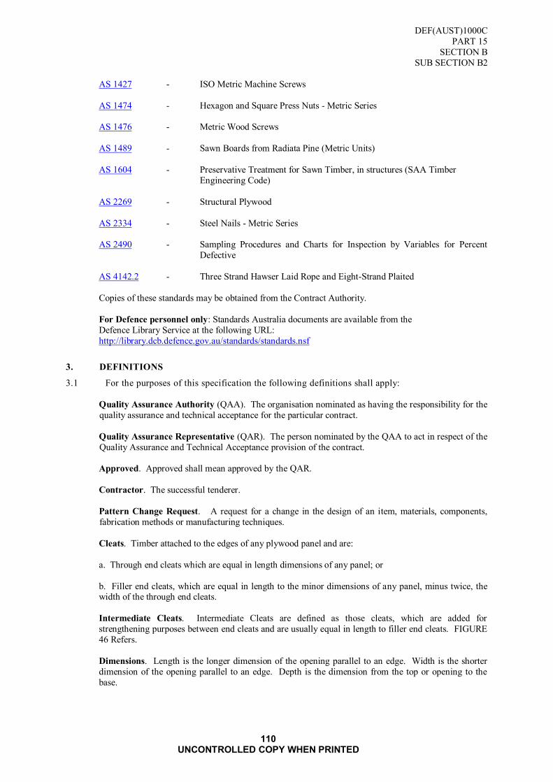
DEF(AUST)1000C
PART 15
SECTION B
SUB SECTION B2
110 UNCONTROLLED COPY WHEN PRINTED
AS 1427 - ISO Metric Machine Screws
AS 1474 - Hexagon and Square Press Nuts - Metric Series
AS 1476 - Metric Wood Screws
AS 1489 - Sawn Boards from Radiata Pine (Metric Units)
AS 1604 - Preservative Treatment for Sawn Timber, in structures (SAA Timber
Engineering Code)
AS 2269 - Structural Plywood
AS 2334 - Steel Nails - Metric Series
AS 2490 - Sampling Procedures and Charts for Inspection by Variables for Percent
Defective
AS 4142.2 - Three Strand Hawser Laid Rope and Eight-Strand Plaited
Copies of these standards may be obtained from the Contract Authority.
For Defence personnel only: Standards Australia documents are available from the
Defence Library Service at the following URL:
http://library.dcb.defence.gov.au/standards/standards.nsf
3. DEFINITIONS
3.1 For the purposes of this specification the following definitions shall apply:
Quality Assurance Authority (QAA). The organisation nominated as having the responsibility for the
quality assurance and technical acceptance for the particular contract.
Quality Assurance Representative (QAR). The person nominated by the QAA to act in respect of the
Quality Assurance and Technical Acceptance provision of the contract.
Approved. Approved shall mean approved by the QAR.
Contractor. The successful tenderer.
Pattern Change Request. A request for a change in the design of an item, materials, components,
fabrication methods or manufacturing techniques.
Cleats. Timber attached to the edges of any plywood panel and are:
a. Through end cleats which are equal in length dimensions of any panel; or
b. Filler end cleats, which are equal in length to the minor dimensions of any panel, minus twice, the width of the through end cleats.
Intermediate Cleats. Intermediate Cleats are defined as those cleats, which are added for
strengthening purposes between end cleats and are usually equal in length to filler end cleats. FIGURE
46 Refers.
Dimensions. Length is the longer dimension of the opening parallel to an edge. Width is the shorter
dimension of the opening parallel to an edge. Depth is the dimension from the top or opening to the
base.

DEF(AUST)1000C
PART 15
SECTION B
SUB SECTION B2
111 UNCONTROLLED COPY WHEN PRINTED
4. REQUIREMENTS
4.1 General
4.1.1 The technical requirements for each box are contained in ANNEXES A to G. These Annexes
shall be read in conjunction with the other requirements of this specification.
4.1.2 Manufacturing Tolerance
The finished box shall conform to the size specified by the Ordering Authority with a tolerance
of + 3 mm on all dimensions.
4.2 Classification
4.2.1 The boxes shall be supplied in the following types and styles:
TYPE 2 - Medium Weight
Style A - Plywood Panel, (Data Sheet No 1)
Style B - Plywood Panel, (Cleated Ends), (Data Sheet No 2)
Style C - Plywood Panel, (Cleated Fully), (Data Sheet No 3)
TYPE 3 - Heavy Weight
Style C - Cleated Panel, Mechanical Lift (Data Sheet No 4)
4.3 Sizes
4.3.1 The recommended sizes of boxes are included in the relevant Data Sheets.
4.4 Coding
4.4.1 The coding used conforms with the modularisation of boxes to the one tonne standard unit load
as defined by DEF(AUST)1000, PART 11 - UNITISATION.
4.4.2 The code system is based on external dimensions and each size is identified by a letter and 3
digits e.g., M 1.2.1 (refer FIGURE 44).
a. M - denotes metric size;
b. 1 - represents the number of boxes across one horizontal face of the pallet;
c. 2 - represents the number of boxes along one horizontal face of the pallet; and
d. 1 - represents the number of boxes in the height above the pallet.
4.4.3 The maximum pallet stacking height shall be in accordance with the one tonne standard unit
load as defined by DEF(AUST) 1000, PART 11 - UNITISATION.

DEF(AUST)1000C
PART 15
SECTION B
SUB SECTION B2
112 UNCONTROLLED COPY WHEN PRINTED
The boxes illustrated above would be coded as M 1.2.1
FIGURE 44 CODING SYSTEM
DEF(AUST)1000C
PART 15
SECTION B
SUB SECTION B2
113 UNCONTROLLED COPY WHEN PRINTED
4.5 Materials
4.5.1 Timber
Species. Unless otherwise specified the timber shall be standard grade in accordance with the requirements of AS 1489.
Hardwood. Unless otherwise specified hardwood timbers shall only be used for skids. When
specified they shall conform to the appropriate quality clauses of this Specification. Softwood
or hardwood shall not be permitted unless immunised against lyctus borer attack in accordance
with AS 1604 or by any other method approved by the QAA.
Reclaimed Timber. Where used, reclaimed timber shall meet all the requirements of this
specification. Timber containing bolt or screw holes, or where the original nail holes coincide
with the alignment of the nailing, or are in excess of four holes per board, shall not be used.
Moisture Content. When calculated in accordance with the oven drying method specified in AS
1489, the moisture content of the timber shall be not greater than 15%.
Staining. Staining that would interfere with painting or identification markings shall not be permitted on any external surface.
Timber Surface. Unless otherwise specified the timber shall be fine sawn on all surfaces.
4.5.2 Plywood
Plywood, unless otherwise specified, shall be structural grade in accordance with AS 2269.
Preservative Treatment. Preservative treatment shall be applied either during manufacture or
after manufacture of the plywood. The manufacturer shall provide copies, of documents,
checked by an independent authority, to the effect that the veneers or the plywood have been
impregnated to required retention, and that such retention is uniform throughout all the veneers
or plywood.
Timber Treatment. All timbers and ply components of the box shall be treated to Hazard Level
5, TABLE 2 of AS 1604. Cutting, shaping or drilling operations are to be carried out before
preservation. However, if this is not possible then the fresh surfaces shall be preserved again.
4.6 Fasteners
4.6.1 General
Individual panels shall be assembled with processed flathead nails, T-bar nails or staples.
Unless otherwise specified combinations of fasteners shall be permitted.
4.6.2 Processed Flathead Nails. Flathead nails shall conform to AS 2334. Where possible the nails
shall be of the resin (cement) coated type of sizes specified in the relevant Data Sheet for each
box.
4.6.3 T-bar Nails. T-bar nails shall be of the size specified. Nails treated against corrosion and are
resin (cement) coated are preferred.
4.6.4 Staples. Staples shall be of minimum 12 mm crown width by 1.6 mm diameter. The length of
the staples shall be such that when driven so that the crown is flush with the plywood panel, they penetrate the cleat to a minimum of 16 mm, without the points protruding. (Alternatively,
staples may be driven through the cleat, into the plywood and clinched on the plywood side.
When this method is chosen the length of the staples used shall be the sum of the thickness of
the plywood and cleat, plus not less than 3 mm for clinching.)
4.6.5 Screws. Assembly screws shall conform to AS 1476. They shall be countersunk and rust
resistant of sizes specified in the relevant Data Sheet for each box.
4.6.6 Bolts, Nuts and Washers. Bolts, nuts and washers shall be supplied and fitted as follows:
a. All bolts shall be complete with nuts and washers and shall be zinc coated conforming, to the
relevant Australian Standards; and
b. Bolt clearance holes in timber shall not be more than the bolt diameter; and
DEF(AUST)1000C
PART 15
SECTION B
SUB SECTION B2
114 UNCONTROLLED COPY WHEN PRINTED
c. All bolts shall be greased prior to insertion in the holes and tightening of the nuts.
4.6.7 Hinges. When specified, hinges shall be in accordance with the requirements of ANNEX A.
4.6.8 Catches. When specified catches shall be in accordance with the requirements of ANNEX A.
4.6.9 Lifting Handles. When specified lifting handles shall be in accordance with the requirements of
ANNEX B.
4.6.10 Handling Facilities. Handling Facilities shall be in accordance with the requirements of
ANNEX C.
4.7 Panel Construction
4.7.1 General. Unless otherwise specified, panels for box styles B and C shall be constructed as
detailed in FIGURE 45 & FIGURE 46. The dimensions of cleats and fasteners shall be as
specified for each style of box in the relevant Data Sheet. Nails and staples shall be driven so
that neither the head nor the crown protrudes above the timber. Slight over driving is permitted
provided this does not exceed more than one-eighth the thickness of the timber.
Staples. Staples shall be driven at approximately 30-degree angles to the general grain
direction. In general, the requirements for nailing shall apply to stapling.
Nailing. Hand driven nails shall be driven at slightly opposing angles to each other. Nails shall
be cleanly driven from the outside except when affixing bottom bearers where the nails shall be
driven from the inside. Protruding points shall be clinched and shall not cause penetration of
any barrier material or box liner, subsequently inserted into the box.
Nailing Pattern. Plywood shall be attached to cleats in accordance with FIGURE 46.
4.8 Assembly
4.8.1 General. Final assembly of each style of box is detailed in the separate Data Sheets appended to
this specification
4.8.2 Type 2 Medium Weight Boxes. Unless otherwise specified the boxes shall be assembled with screws in accordance with paragraph 4.6.5.
4.8.3 Type 3 Heavy Weight Boxes. Unless otherwise specified the boxes shall be assembled with
bolts in accordance with paragraph 4.6.6.
4.8.4 Drain Holes. For style C boxes drain holes shall be drilled through the cleats of the top panel.
The diameter of the drain holes shall be a minimum of 10 mm and the lowest point of the drain
hole shall coincide with the bottom of the cleat. One hole shall be drilled for each compartment
of the top panel; in the outer edge cleats, centrally spaced, and shall not interfere with screws,
bolts or cleats.
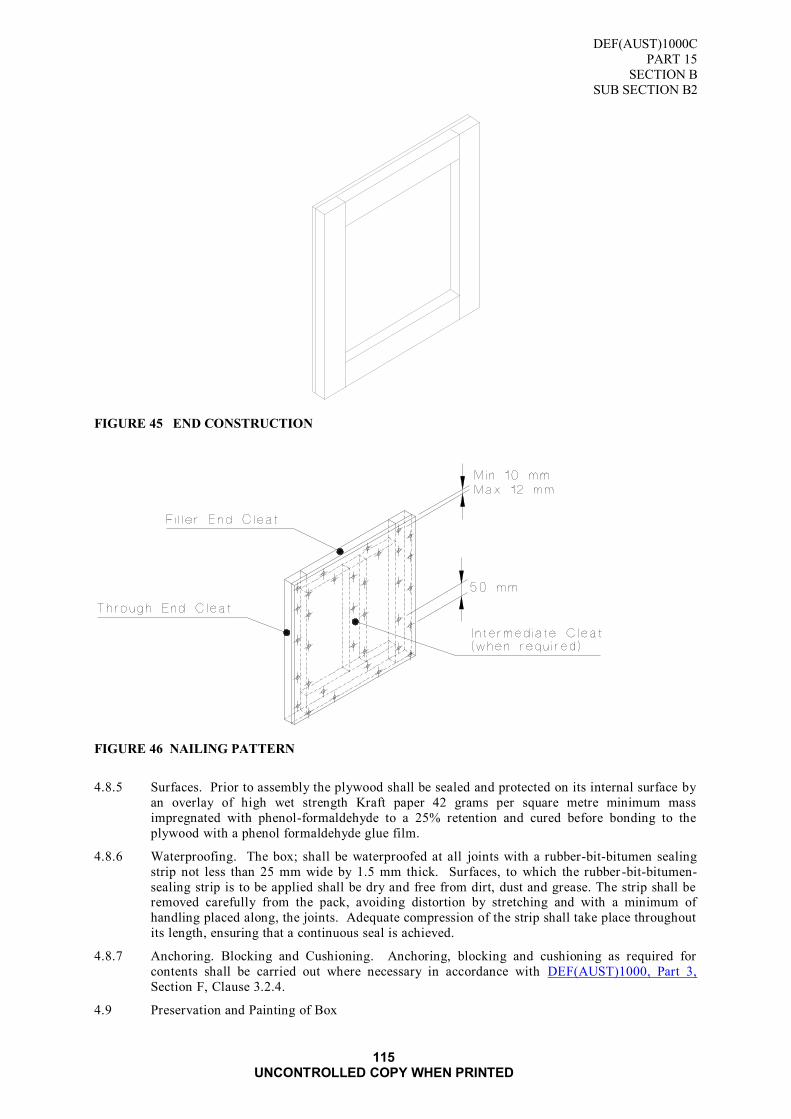
DEF(AUST)1000C
PART 15
SECTION B
SUB SECTION B2
115 UNCONTROLLED COPY WHEN PRINTED
FIGURE 45 END CONSTRUCTION
FIGURE 46 NAILING PATTERN
4.8.5 Surfaces. Prior to assembly the plywood shall be sealed and protected on its internal surface by
an overlay of high wet strength Kraft paper 42 grams per square metre minimum mass
impregnated with phenol-formaldehyde to a 25% retention and cured before bonding to the
plywood with a phenol formaldehyde glue film.
4.8.6 Waterproofing. The box; shall be waterproofed at all joints with a rubber-bit-bitumen sealing
strip not less than 25 mm wide by 1.5 mm thick. Surfaces, to which the rubber -bit-bitumen-
sealing strip is to be applied shall be dry and free from dirt, dust and grease. The strip shall be removed carefully from the pack, avoiding distortion by stretching and with a minimum of
handling placed along, the joints. Adequate compression of the strip shall take place throughout
its length, ensuring that a continuous seal is achieved.
4.8.7 Anchoring. Blocking and Cushioning. Anchoring, blocking and cushioning as required for
contents shall be carried out where necessary in accordance with DEF(AUST)1000, Part 3,
Section F, Clause 3.2.4.
4.9 Preservation and Painting of Box

DEF(AUST)1000C
PART 15
SECTION B
SUB SECTION B2
116 UNCONTROLLED COPY WHEN PRINTED
4.9.1 Preservation. Preservation of all timbers and plywood components shall be in accordance with
paragraphs 4.5.2.2 and 4.5.2.3.
4.9.2 Painting. Unless otherwise specified by the Ordering Authority, the boxes shall be painted externally only and in accordance with the following:
a. All surfaces shall be dry and thoroughly cleaned prior to painting,
b. One primer coat;
c. One undercoat;
d. Two finishing coats. The paint shall be enamel
e. All workmanship shall be to the requirements of the Ordering Authority.
4.10 Markings
4.10.1 Marking of Boxes. Identification and marking shall be in accordance with DEF(AUST)1000,
PART 5 - Marking of Packages for Consignment and Storage.
4.10.2 Warning and cautionary markings in accordance with DEF(AUST)1000, PART 5 shall be
applied as follows:
a. Use No Hooks or Grabs;
b. This Side Up;
c. Open This Side for Inspection;
d. Open This Side for Identification (when applicable);
e. Technical Manual This Box (where more than one box is involved; and
f. Other markings as required.
4.11 Government Ownership
4.11.1 When supplied in unassembled form, each panel shall be marked with the Broad Arrow Symbol
in accordance with DEF(AUST)5047 - Identification Marking of Stores and Equipment.
4.11.2 When supplied in assembled form, one side and the lid panel shall be marked with the Broad
Arrow Symbol in accordance with DEF(AUST)5047.
4.12 Delivery
4.12.1 The conditions of delivery and mode of transport shall be stated in the procurement documents
by the Ordering Authority.
4.13 Alternative Packing Methods
NOTE: Minimisation of the use of virgin materials as alternative packaging materials is encouraged.
4.13.1 The tenderer shall submit costs for wooden boxes in accordance with this specification.
Alternative packaging methods including the use of aluminium, or steel breakdown containers
may be proposed by the tenderer and may be considered for acceptance. Particulars of
alternative packaging and costs shall be detailed in the Tender Schedule as a separate item.
Where an alternative is tendered, proof of strength equivalent to timber boxes shall be
submitted.
5. QUALITY ASSURANCE PROVISIONS
5.1 The Contractor shall maintain effective control of the quality of supplies and/or services
(including subcontracts), provide test facilities and perform all examinations and tests stated in
the contract to demonstrate conformance of supplies and/or services to the technical

DEF(AUST)1000C
PART 15
SECTION B
SUB SECTION B2
117 UNCONTROLLED COPY WHEN PRINTED
requirements of the contract and shall offer for acceptance only supplies and/or services that
conform to these requirements.
5.2 The Contractor shall be responsible for the provision of objective evidence demonstrating that the controls applied and inspections carried out are effective.
5.3 The Ordering Authority is the Quality Assurance Authority and reserves the right to perform
any examinations or tests to ensure that supplies and/or services conform to the technical
requirements of the contract.
5.4 Acceptance of all supplies and services shall be subject to agreement by the Ordering Authority
that the quality requirements have been fulfilled. The Quality Assurance Authority reserves the
right to reject any supplies which fail to meet the technical requirements of this contract.
5.5 The Request for Tender and contract shall nominate the Ordering Authority and acceptance
provisions and the requirements for Contractor's quality control.
5.6 Sampling Procedure
5.6.1 Where compliance with the requirements of this specification is based on statistical sampling and inspection, the sampling procedures and operating characteristics of the sample plan shall
be subject to the approval of the QAA. The QAA reserves the right to use the following
documents for verifying that the Contractor‟s sampling plans are effective, wherever they
determine them to be applicable. Applicable documents are as follows:
a. AS 1199; and
b. AS 2490.
5.6.2 Where AS 1199 is used the following shall be adhered to:
a. Inspection Level 2 shall be used; and
b. The classification of defects shall be in accordance with AS 1199 TABLE I.
5.7 Acceptable Quality Levels
The acceptable quality levels (AQL) shall be as follows:
a. Special defects - 0.4%;
b. Major defects - 0.1%; and
c. Minor defects - 4.0%.
5.8 Classification of Defects
The classification of defects is detailed in TABLE 44.
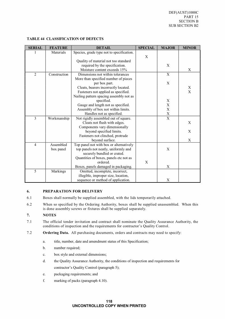
DEF(AUST)1000C
PART 15
SECTION B
SUB SECTION B2
118 UNCONTROLLED COPY WHEN PRINTED
TABLE 44 CLASSIFICATION OF DEFECTS
SERIAL FEATURE DETAIL SPECIAL MAJOR MINOR
1 Materials Species, grade type not to specification.
X
Quality of material not too standard
required by the specification.
X
Moisture content exceeds 15% X
2 Construction Dimensions not within tolerances X
More than specified number of pieces
per box part.
X
Cleats, bearers incorrectly located. X
Fasteners not applied as specified. X
Nailing pattern spacing assembly not as
specified.
X
Gauge and length not as specified. X
Assembly of box not within limits. X Handles not as specified. X
3 Workmanship Not rigidly assembled out of square. X Cleats not flush with edges. X
Components vary dimensionally
beyond specified limits.
X
Fasteners not clinched, protrude
beyond surface.
X
4 Assembled
box panel
Top panel not with box or alternatively
top panels not neatly, uniformly and
securely bundled or crated.
X
Quantities of boxes, panels etc not as
ordered.
X
Boxes, panels damaged in packaging. X
5 Markings Omitted, incomplete, incorrect,
illegible, improper size, location,
sequence or method of application.
X
6. PREPARATION FOR DELIVERY
6.1 Boxes shall normally be supplied assembled, with the lids temporarily attached.
6.2 When so specified by the Ordering Authority, boxes shall be supplied unassembled. When this
is done assembly screws or fixtures shall be supplied separately.
7. NOTES
7.1 The official tender invitation and contract shall nominate the Quality Assurance Authority, the
conditions of inspection and the requirements for contractor‟s Quality Control.
7.2 Ordering Data. All purchasing documents, orders and contracts may need to specify:
a. title, number, date and amendment status of this Specification;
b. number required;
c. box style and external dimensions;
d. the Quality Assurance Authority, the conditions of inspection and requirements for
contractor‟s Quality Control (paragraph 5);
e. packaging requirements; and
f. marking of packs (paragraph 4.10).

DEF(AUST)1000C
PART 15
SECTION B
SUB SECTION B2
DATA SHEET No.1
119 UNCONTROLLED COPY WHEN PRINTED
DATA SHEET No. 1
TYPE 2 - MEDIUM WEIGHT BOXES
STYLE A - PLYWOOD PANEL
1. SCOPE
1.1 This Annex covers the technical requirements of Type 2 Style A boxes, and shall be read in
conjunction with the relevant paragraphs of the specification.
2. DESCRIPTION
2.1 Lightweight, reusable boxes of plywood panel construction. The style of box shall be as shown
in FIGURE 47 & FIGURE 48.
3. INTENDED USE
3.1 Used for the packaging of a range of stores where the mass of box and contents does not exceed
35 kg, and the external dimensions of the box do not exceed 1100 mm length, 550 mm width, or 850 mm overall height.
4. REQUIREMENTS
4.1 The materials used in the construction and assembly of the box shall be as detailed in TABLE
45.
TABLE 45 MATERIALS LIST
SERIAL MATERIAL REQUIREMENTS (mm)
1. Box Panels
a. Plywood - thicknesses 19 (Sides, Top and Base),
10 (Ends) b. Timber
Cleats - width
- thickness
50
19
2. Fasteners
a. Panels
Nails - length
- diameter
25
1.8
Staples - leg length
- crown length
- diameter
35
12
1.6
3. Box Assembly
Screws - length
- size No
40
10
Nails - length - diameter
50 2.8
4.2 Manufacture
4.2.1 Panels. Each panel shall be formed from a single sheet of plywood.
4.3 Final Assembly
4.3.1 Side Panels and Base. Unless otherwise specified assembly shall be by screw fasteners.
Clearance holes shall be drilled for the screw shanks.
4.3.2 Screw Location. The location and number of assembly screws shall be as listed below.
One screw shall be placed within 10 mm from any end.
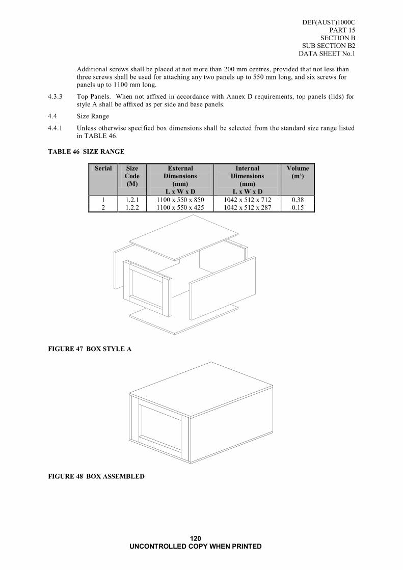
DEF(AUST)1000C
PART 15
SECTION B
SUB SECTION B2
DATA SHEET No.1
120 UNCONTROLLED COPY WHEN PRINTED
Additional screws shall be placed at not more than 200 mm centres, provided that not less than
three screws shall be used for attaching any two panels up to 550 mm long, and six screws for panels up to 1100 mm long.
4.3.3 Top Panels. When not affixed in accordance with Annex D requirements, top panels (lids) for
style A shall be affixed as per side and base panels.
4.4 Size Range
4.4.1 Unless otherwise specified box dimensions shall be selected from the standard size range listed
in TABLE 46.
TABLE 46 SIZE RANGE
Serial Size
Code
(M)
External
Dimensions
(mm)
L x W x D
Internal
Dimensions
(mm)
L x W x D
Volume
(m³)
1 1.2.1 1100 x 550 x 850 1042 x 512 x 712 0.38
2 1.2.2 1100 x 550 x 425 1042 x 512 x 287 0.15
FIGURE 47 BOX STYLE A
FIGURE 48 BOX ASSEMBLED
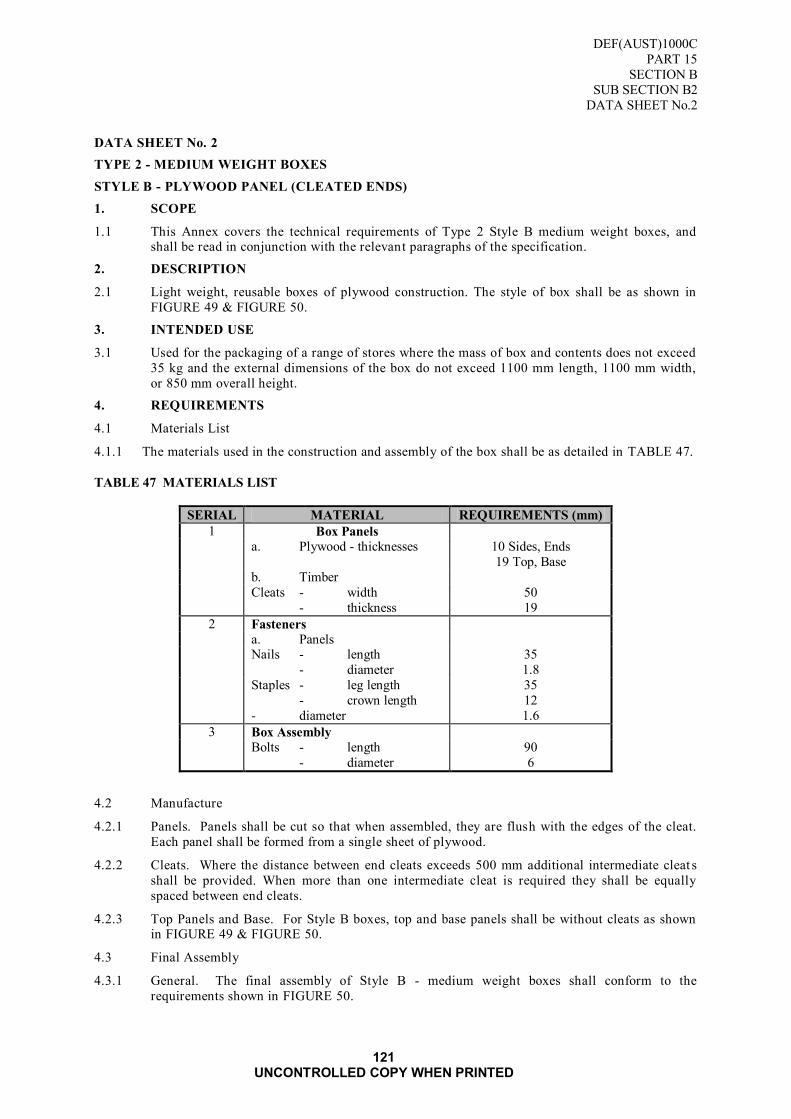
DEF(AUST)1000C
PART 15
SECTION B
SUB SECTION B2
DATA SHEET No.2
121 UNCONTROLLED COPY WHEN PRINTED
DATA SHEET No. 2
TYPE 2 - MEDIUM WEIGHT BOXES
STYLE B - PLYWOOD PANEL (CLEATED ENDS)
1. SCOPE
1.1 This Annex covers the technical requirements of Type 2 Style B medium weight boxes, and shall be read in conjunction with the relevant paragraphs of the specification.
2. DESCRIPTION
2.1 Light weight, reusable boxes of plywood construction. The style of box shall be as shown in
FIGURE 49 & FIGURE 50.
3. INTENDED USE
3.1 Used for the packaging of a range of stores where the mass of box and contents does not exceed
35 kg and the external dimensions of the box do not exceed 1100 mm length, 1100 mm width,
or 850 mm overall height.
4. REQUIREMENTS
4.1 Materials List
4.1.1 The materials used in the construction and assembly of the box shall be as detailed in TABLE 47.
TABLE 47 MATERIALS LIST
SERIAL MATERIAL REQUIREMENTS (mm)
1 Box Panels
a. Plywood - thicknesses 10 Sides, Ends
19 Top, Base
b. Timber
Cleats - width
- thickness
50
19
2 Fasteners
a. Panels Nails - length
- diameter
35
1.8
Staples - leg length
- crown length
- diameter
35
12
1.6
3 Box Assembly
Bolts - length
- diameter
90
6
4.2 Manufacture
4.2.1 Panels. Panels shall be cut so that when assembled, they are flush with the edges of the cleat.
Each panel shall be formed from a single sheet of plywood.
4.2.2 Cleats. Where the distance between end cleats exceeds 500 mm additional intermediate cleat s
shall be provided. When more than one intermediate cleat is required they shall be equally
spaced between end cleats.
4.2.3 Top Panels and Base. For Style B boxes, top and base panels shall be without cleats as shown in FIGURE 49 & FIGURE 50.
4.3 Final Assembly
4.3.1 General. The final assembly of Style B - medium weight boxes shall conform to the
requirements shown in FIGURE 50.

DEF(AUST)1000C
PART 15
SECTION B
SUB SECTION B2
DATA SHEET No.2
122 UNCONTROLLED COPY WHEN PRINTED
4.3.2 Bolt Location. Bolts shall be fitted at not more than 600 mm centres and within 250 mm from
any end. Not less than 2 bolts shall be used for bolting together any two adjoining panel edges.
4.4 Size Range
4.4.1 Box dimensions shall be selected from the standard size range listed in TABLE 48.
TABLE 48
Serial Size
Code
(M)
External
Dimensions
(mm)
L x W x D
Internal
Dimensions
(mm)
L x W x D
Volume
(m³)
1 1.1.2 1100 x 1100 x 425 1042 x 1042 x 287 0.3
2 1.2.1 1100 x 550 x 850 1042 x 492 x 712 0.36
3 1.2.2 1100 x 550 x 425 1042 x 492 x 287 0.15
FIGURE 49 BOX STYLE B
FIGURE 50 BOX ASSEMBLED
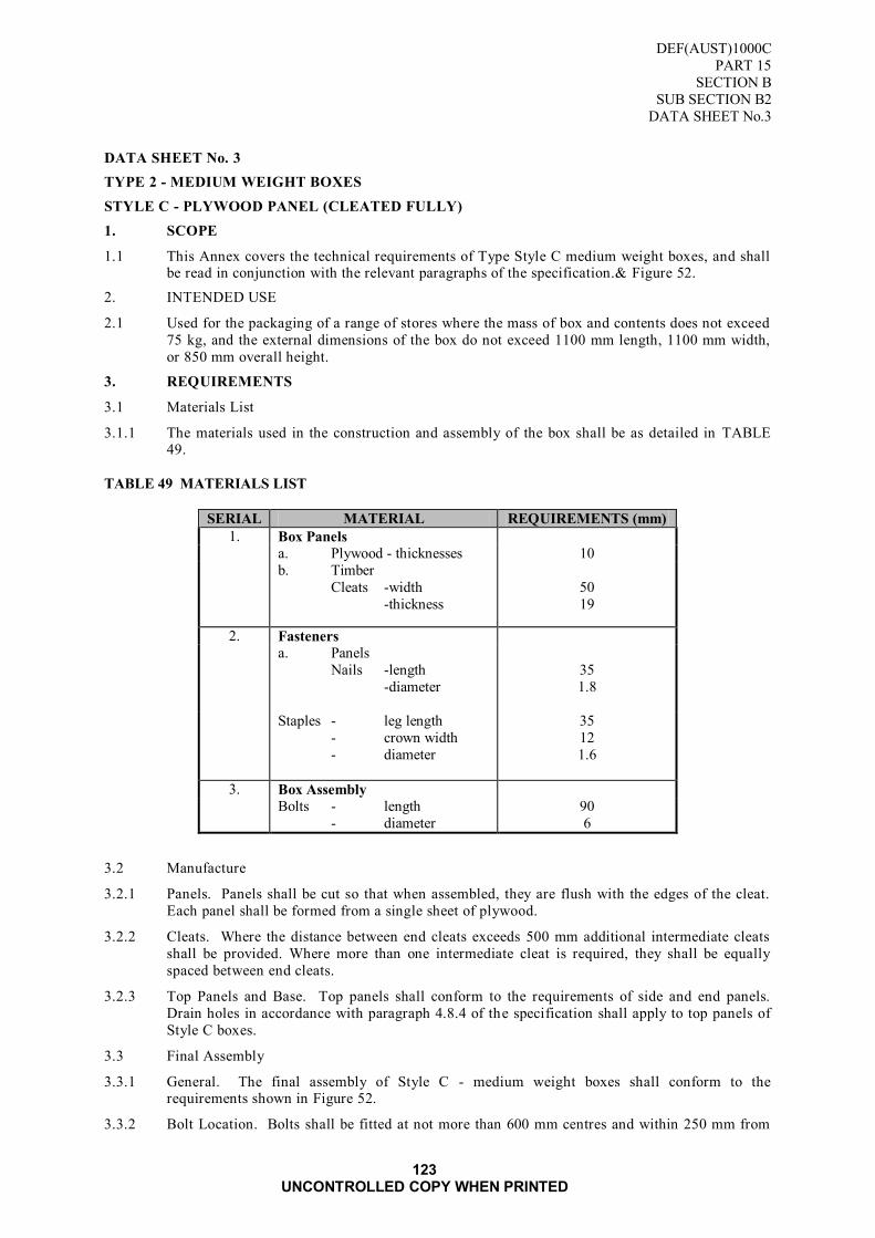
DEF(AUST)1000C
PART 15
SECTION B
SUB SECTION B2
DATA SHEET No.3
123 UNCONTROLLED COPY WHEN PRINTED
DATA SHEET No. 3
TYPE 2 - MEDIUM WEIGHT BOXES
STYLE C - PLYWOOD PANEL (CLEATED FULLY)
1. SCOPE
1.1 This Annex covers the technical requirements of Type Style C medium weight boxes, and shall be read in conjunction with the relevant paragraphs of the specification.& Figure 52.
2. INTENDED USE
2.1 Used for the packaging of a range of stores where the mass of box and contents does not exceed
75 kg, and the external dimensions of the box do not exceed 1100 mm length, 1100 mm width,
or 850 mm overall height.
3. REQUIREMENTS
3.1 Materials List
3.1.1 The materials used in the construction and assembly of the box shall be as detailed in TABLE 49.
TABLE 49 MATERIALS LIST
SERIAL MATERIAL REQUIREMENTS (mm)
1. Box Panels
a. Plywood - thicknesses 10
b. Timber
Cleats -width
-thickness
50
19
2. Fasteners
a. Panels
Nails -length
-diameter
35
1.8
Staples - leg length
- crown width
- diameter
35
12
1.6
3. Box Assembly
Bolts - length
- diameter
90
6
3.2 Manufacture
3.2.1 Panels. Panels shall be cut so that when assembled, they are flush with the edges of the cleat.
Each panel shall be formed from a single sheet of plywood.
3.2.2 Cleats. Where the distance between end cleats exceeds 500 mm additional intermediate cleats
shall be provided. Where more than one intermediate cleat is required, they shall be equally
spaced between end cleats.
3.2.3 Top Panels and Base. Top panels shall conform to the requirements of side and end panels.
Drain holes in accordance with paragraph 4.8.4 of the specification shall apply to top panels of
Style C boxes.
3.3 Final Assembly
3.3.1 General. The final assembly of Style C - medium weight boxes shall conform to the requirements shown in Figure 52.
3.3.2 Bolt Location. Bolts shall be fitted at not more than 600 mm centres and within 250 mm from

DEF(AUST)1000C
PART 15
SECTION B
SUB SECTION B2
DATA SHEET No.3
124 UNCONTROLLED COPY WHEN PRINTED
any end. Not less than two bolts shall be used for bolting together any two adjoining panel
edges.
3.4 Size Range
3.4.1 Box dimensions shall be selected from the standard size range listed in TABLE 50.
TABLE 50 SIZE RANGE
Serial Size
Code
(M)
External
Dimensions
(mm)
L x W x D
Internal
Dimensions
(mm)
L x W x D
Volume
(m³)
1. 1.1.2 1100 x 1100 x 425 1042 x 1042 x 267 0.3
2. 1.2.1 1100 x 550 x 850 1042 x 492 x 692 0.36
3. 1.2.2 1100 x 550 x 425 1042 x 492 x 267 0.13
FIGURE 51 BOX STYLE C
Figure 52 BOX ASSEMBLED
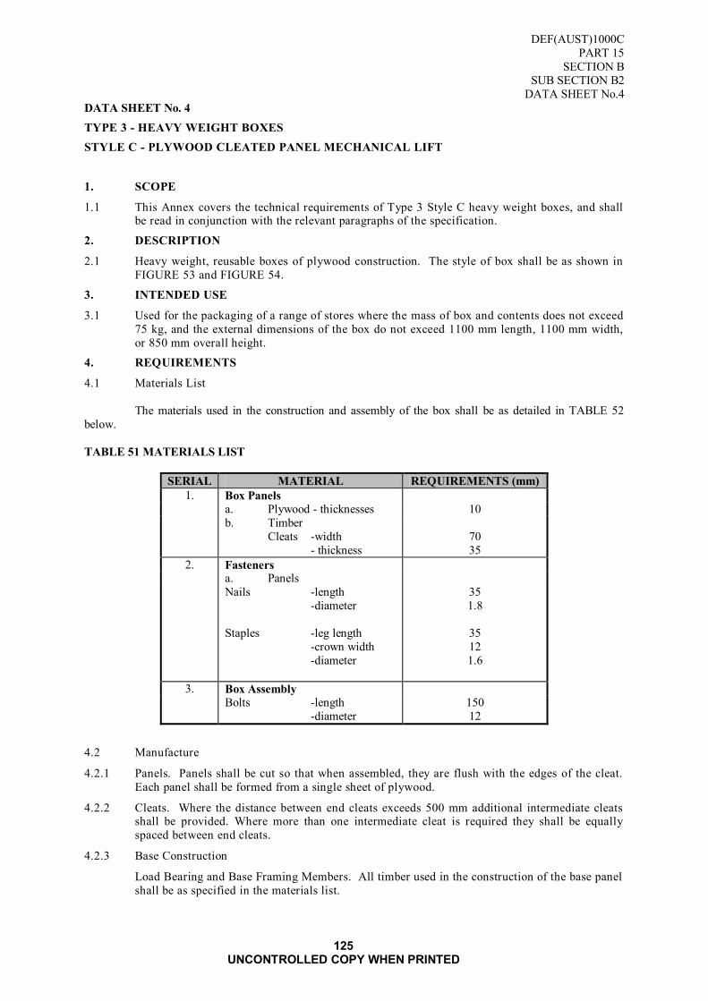
DEF(AUST)1000C
PART 15
SECTION B
SUB SECTION B2
DATA SHEET No.4
125 UNCONTROLLED COPY WHEN PRINTED
DATA SHEET No. 4
TYPE 3 - HEAVY WEIGHT BOXES
STYLE C - PLYWOOD CLEATED PANEL MECHANICAL LIFT
1. SCOPE
1.1 This Annex covers the technical requirements of Type 3 Style C heavy weight boxes, and shall be read in conjunction with the relevant paragraphs of the specification.
2. DESCRIPTION
2.1 Heavy weight, reusable boxes of plywood construction. The style of box shall be as shown in
FIGURE 53 and FIGURE 54.
3. INTENDED USE
3.1 Used for the packaging of a range of stores where the mass of box and contents does not exceed
75 kg, and the external dimensions of the box do not exceed 1100 mm length, 1100 mm width,
or 850 mm overall height.
4. REQUIREMENTS
4.1 Materials List
The materials used in the construction and assembly of the box shall be as detailed in TABLE 52
below.
TABLE 51 MATERIALS LIST
SERIAL MATERIAL REQUIREMENTS (mm)
1. Box Panels
a. Plywood - thicknesses 10
b. Timber
Cleats -width
- thickness
70
35
2. Fasteners a. Panels
Nails -length
-diameter
35
1.8
Staples -leg length
-crown width
-diameter
35
12
1.6
3. Box Assembly
Bolts -length
-diameter
150
12
4.2 Manufacture
4.2.1 Panels. Panels shall be cut so that when assembled, they are flush with the edges of the cleat.
Each panel shall be formed from a single sheet of plywood.
4.2.2 Cleats. Where the distance between end cleats exceeds 500 mm additional intermediate cleats shall be provided. Where more than one intermediate cleat is required they shall be equally
spaced between end cleats.
4.2.3 Base Construction
Load Bearing and Base Framing Members. All timber used in the construction of the base panel
shall be as specified in the materials list.
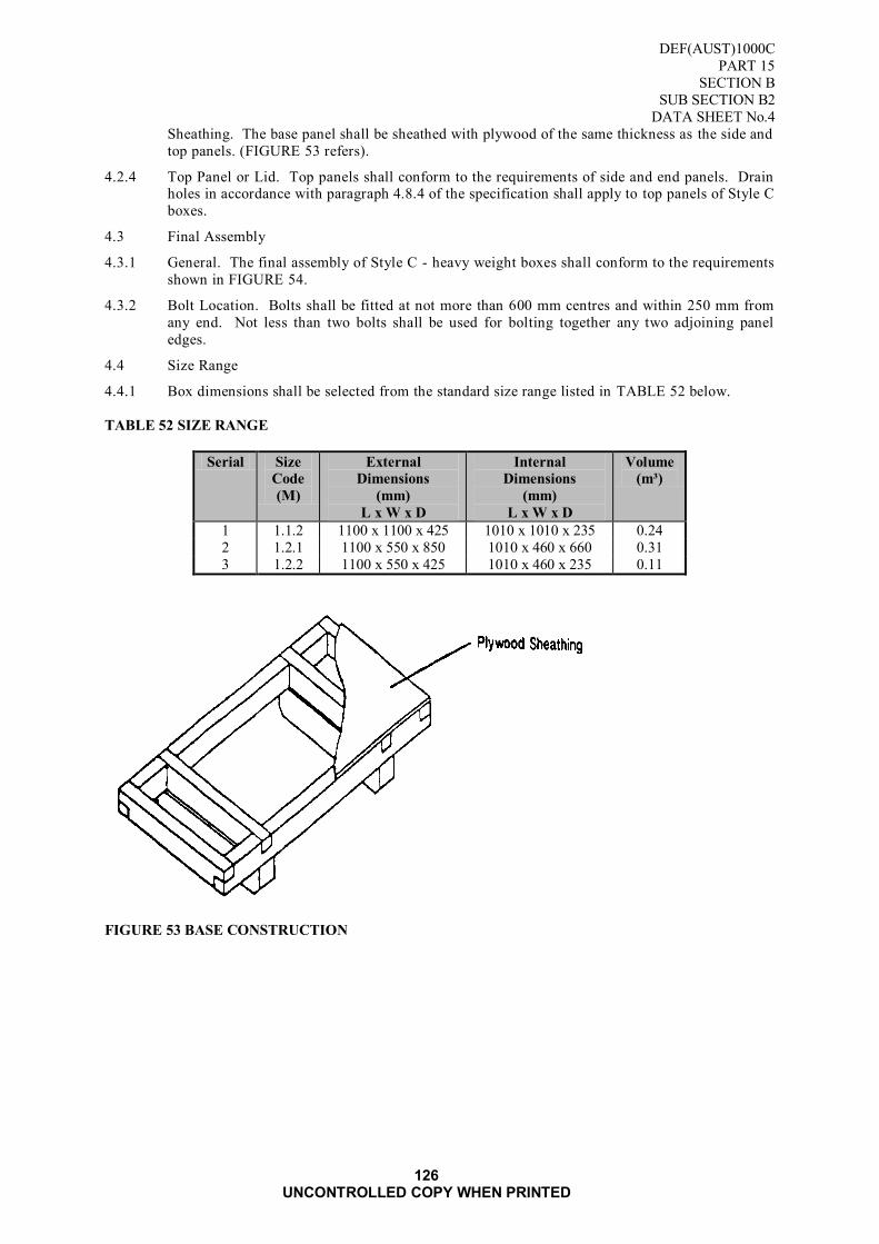
DEF(AUST)1000C
PART 15
SECTION B
SUB SECTION B2
DATA SHEET No.4
126 UNCONTROLLED COPY WHEN PRINTED
Sheathing. The base panel shall be sheathed with plywood of the same thickness as the side and
top panels. (FIGURE 53 refers).
4.2.4 Top Panel or Lid. Top panels shall conform to the requirements of side and end panels. Drain holes in accordance with paragraph 4.8.4 of the specification shall apply to top panels of Style C
boxes.
4.3 Final Assembly
4.3.1 General. The final assembly of Style C - heavy weight boxes shall conform to the requirements
shown in FIGURE 54.
4.3.2 Bolt Location. Bolts shall be fitted at not more than 600 mm centres and within 250 mm from
any end. Not less than two bolts shall be used for bolting together any two adjoining panel
edges.
4.4 Size Range
4.4.1 Box dimensions shall be selected from the standard size range listed in TABLE 52 below.
TABLE 52 SIZE RANGE
Serial Size
Code
(M)
External
Dimensions
(mm)
L x W x D
Internal
Dimensions
(mm)
L x W x D
Volume
(m³)
1 1.1.2 1100 x 1100 x 425 1010 x 1010 x 235 0.24
2 1.2.1 1100 x 550 x 850 1010 x 460 x 660 0.31
3 1.2.2 1100 x 550 x 425 1010 x 460 x 235 0.11
FIGURE 53 BASE CONSTRUCTION

DEF(AUST)1000C
PART 15
SECTION B
SUB SECTION B2
DATA SHEET No.4
127 UNCONTROLLED COPY WHEN PRINTED
FIGURE 54 BOX ASSEMBLED

DEF(AUST)1000C
PART 15
SECTION B
SUB SECTION B2
DATA SHEET No.4
128 UNCONTROLLED COPY WHEN PRINTED
Blank Page

DEF(AUST)1000C
PART 15
SECTION B
SUB SECTION B2
ANNEX A
129 UNCONTROLLED COPY WHEN PRINTED
ANNEX A
METHOD OF CLOSURE
A1. SCOPE
A1.1 This Annex describes methods of closure suitable for style A boxes. When specified hinges and
retaining catches can be fitted to the lids offering ease of opening and closure.
A1.2 Hinges and catches are to be fitted only when specifically ordered and shall be as specified by the Ordering Authority.
A2. DESCRIPTION
A2.1 Hinges. Unless otherwise specified hinges shall be selected from the following:
a. Strap hinges;
b. Tee hinges;
c. Butt hinges; or
d. Lift-off, reflex type hinges or equivalent.
A2.2 Catches. Closure catches shall be as specified by the Ordering Authority, and selected from the
following, as shown in FIGURE 55:
a. hasps and staples; or
b. toggle catches.
A3. REQUIREMENTS
A3.1 Hinges. Hinges treated against corrosion are preferred, and shall be of sufficient length and width to
ensure repeated use without interfering with the closure of the lid.
A3.2 Catches. Catches treated against corrosion are preferred, and when fitted shall secure the lid so that no
movement will result when closed.
A4. ASSEMBLY
A4.1 Fitting of Hinges. Unless otherwise specified, hinges shall be attached to the assembled boxes with
screws. When strap, tee or butt hinges are used a chain shall be attached between the end of the box
and the lid of a suitable size and length to restrict the lid from causing damage to the hinges when
opened (FIGURE 56 refers).

DEF(AUST)1000C
PART 15
SECTION B
SUB SECTION B2
ANNEX A
130 UNCONTROLLED COPY WHEN PRINTED
EXAMPLE OF COMMERCIALLY AVAILABLE
TOGGLE CATCH LEVERS AND CATCH PLATES
HASP AND STAPLE
FIGURE 55 CLOSURE CATCHES
A4.2 Fitting of Catches. Unless otherwise specified catches shall be fastened with round head, machine
thread bolts or grooved pop-rivets of appropriate length and diameter. Where catches are fitted external
cleats of timber are to be fitted in a manner to afford protection. (FIGURE 56 refers).

DEF(AUST)1000C
PART 15
SECTION B
SUB SECTION B2
ANNEX A
131 UNCONTROLLED COPY WHEN PRINTED
FIGURE 56 TYLE A BOX WITH HINGED LID

DEF(AUST)1000C
PART 15
SECTION B
SUB SECTION B2
ANNEX A
132 UNCONTROLLED COPY WHEN PRINTED
Blank Page

DEF(AUST)1000C
PART 15
SECTION B
SUB SECTION B2
ANNEX B
133 UNCONTROLLED COPY WHEN PRINTED
ANNEX B
LIFTING HANDLES
B1. SCOPE
B1.1 This Annex describes the lifting handles, which may be fitted to boxes when required. Handles are
only to be fitted when specifically ordered and shall be as specified by the Ordering Authority.
B2. DESCRIPTION
B2.1 Unless otherwise specified, lifting handles shall be selected from those detailed below.
B2.1.1 Type A Metal Handle. The type A handle shall be pressed steel of a type and size similar to that
shown in FIGURE 57. Metal handles, unless otherwise specified, shall be affixed to the boxes using
mushroom head machine thread screws of appropriate length and diameter conforming to AS 1427.
The screws shall be fastened with square pressed nuts conforming to AS 1474.
FIGURE 57 TYPE A HANDLE. BAIL. STEEL NSN 5340-66-014-1698

DEF(AUST)1000C
PART 15
SECTION B
SUB SECTION B2
ANNEX B
134 UNCONTROLLED COPY WHEN PRINTED
B2.1.2 Type B - Rope Handle with Metal Bracket. The type B handle shall be a pressed steel bracket of a type and size similar to that shown in FIGURE 58, with a rope handle. The rope shall conform to AS
4142.2, and shall be knotted as shown in FIGURE 59. Unless otherwise specified, the bracket shall be
affixed to boxes in the same manner as type A.
TOP FIGURE 58 BRACKET
BOTTOM FIGURE 59 HANDLE ROPE KNOT

DEF(AUST)1000C
PART 15
SECTION B
SUB SECTION B2
ANNEX B
135 UNCONTROLLED COPY WHEN PRINTED
B2.1.3 Type C - Webbing Handle with Metal Bracket. The type C handle shall be a pressed steel bracket of a type and size similar to that shown in FIGURE 60 with a webbing handle. The webbing shall
be selected from the range specified in ARMY(AUST)6713 and shall be attached to the bracket as
shown in FIGURE 61. Unless otherwise specified the bracket shall be affixed to boxes in the same
manner as type A handles.
FIGURE 60 BRACKET DETAILS
FIGURE 61 DETAILS OF WEBBING HANDLE
B2.1.4 Type D - Rope Handle with Horizontal Wood Block. The type D handle shall be a wood block
conforming to AS 1489 manufactured in accordance with
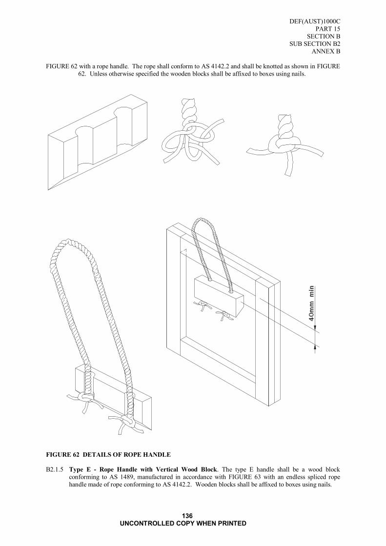
DEF(AUST)1000C
PART 15
SECTION B
SUB SECTION B2
ANNEX B
136 UNCONTROLLED COPY WHEN PRINTED
FIGURE 62 with a rope handle. The rope shall conform to AS 4142.2 and shall be knotted as shown in FIGURE
62. Unless otherwise specified the wooden blocks shall be affixed to boxes using nails.
FIGURE 62 DETAILS OF ROPE HANDLE
B2.1.5 Type E - Rope Handle with Vertical Wood Block. The type E handle shall be a wood block
conforming to AS 1489, manufactured in accordance with FIGURE 63 with an endless spliced rope
handle made of rope conforming to AS 4142.2. Wooden blocks shall be affixed to boxes using nails.

DEF(AUST)1000C
PART 15
SECTION B
SUB SECTION B2
ANNEX B
137 UNCONTROLLED COPY WHEN PRINTED
FIGURE 63 DETAILS OF TYPE E ROPE HANDLE

DEF(AUST)1000C
PART 15
SECTION B
SUB SECTION B2
ANNEX B
138 UNCONTROLLED COPY WHEN PRINTED
Blank Page

DEF(AUST)1000C
PART 15
SECTION B
SUB SECTION B2
ANNEX C
139 UNCONTROLLED COPY WHEN PRINTED
ANNEX C
HANDLING FACILITIES
C1. SCOPE
C1.1 This Annex describes the handling aids, which can be fitted to wooden boxes. Handling aids in
accordance with TABLE I of Annex G are only to be fitted when specifically ordered.
C2. DESCRIPTION
C2.1 Handling aids are provided on wooden boxes to allow for ease of mechanical or manual movement.
Unless otherwise specified lifting handles shall be selected from TABLE I below:
TABLE 53 SELECTION OF HANDLING AIDS
Serial Gross Mass
of Package
Length of
Package
Handling Aid
l Up to 35 kg Under 1 m None
2 Up to 35 kg Over 1 m Fork Lift Skids and/or 2
Lifting Handles
3 35 kg to 75 kg Under 1 m 2 Lifting Handles
4 35 kg to 75 kg Over 1 m Fork Lift Skids and/or 2
Lifting Handles
5 Over 75 kg All Sizes Fork Lift Skids and/or
Sling Devices
C3. REQUIREMENTS
C3.1 Handles. When specified, handles shall be selected from the range in Annex F.
C3.2 Skids. Skids shall be fitted to wooden boxes in accordance with Annex G.
C3.2.1 Timber. Skids shall be made from matured hardwood timber of minimum strength group SD4 as
detailed in TABLE B1, Appendix B to AS 1720.
C3.3.2 Manufacture
C3.3.2.1 The skids shall be of the same size, a minimum of 100 mm in height and 75 mm in width. The ends
shall be provided with a 20 mm chamfer with the bottom edge dressed, and when fitted shall not protrude beyond the outer edges of the boxes.
C3.3.3 Assembly
C3.3.3.1 Skids shall be bolted to the base panels of all box styles with 12 mm cup head, square neck bolts.
The bolts shall be located not more than 150 mm from each end and at intervals not exceeding 600
mm. The nuts shall be recessed into the lower side of the bottom skids and there shall be no metal
projecting beyond the lower edge of the skid.
C3.3.3.2 For boxes up to 1100 mm in length one skid shall be placed at 220 mm centres from each end
measured across the width of the box. Maximum 150 mm centres for skids on boxes up to 550 mm in length. (FIGURE 64 refers)
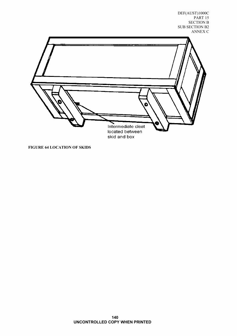
DEF(AUST)1000C
PART 15
SECTION B
SUB SECTION B2
ANNEX C
140 UNCONTROLLED COPY WHEN PRINTED
FIGURE 64 LOCATION OF SKIDS

DEF(AUST)1000C
PART 15
SECTION B
SUB SECTION B3
141 UNCONTROLLED COPY WHEN PRINTED
SUB SECTION B3: DESIGN AND CONSTRUCTION OF TRANSPORT AND STORAGE
CONTAINERS
1. SCOPE
1.1 This Specification details the requirements for the manufacture and supply of bolted transport and
storage containers.
2. APPLICABLE DOCUMENTS
2.1 Reference may be necessary to the latest issue of the following documents.
Australian Paint Approval Scheme
The following specifications are available at the following URL: http://www.apas.gov.au/
APAS 0006/1 Army Olive Drab flat enamel (equipment)
APAS 0006/2 Army Olive Drab low gloss enamel (equipment)
APAS 0181 - Solvent borne wood primer (buildings)
Standards Australia
AS 01 - Glossary of Terms used in Timber Standards
AS 1554 - Structural Steel Welding
AS 1604 - Preservative Treatment of Sawn Timber, Veneer and Plywood
AS 1720 - Timber Structures Code
AS 2098 - Methods of Test for Veneer and Plywood
AS 2269 - Structural Plywood
AS 2271 - Plywood and Blockboard for Exterior Use
AS 2289 - Glossary of Terms Used in the Plywood Industry
AS 2543 - Nomenclature of Australian Timbers
AS 2754 - Adhesives for Plywood Manufacture
Details of where copies of Australian Standard may be obtained from are displayed at : SAI Global
For Defence personnel only: Standards Australia documents are available from the
Defence Library Service at the following URL:
http://library.dcb.defence.gov.au/standards/standards.nsf
British Standards
BS 2837 - Steel Link and Strap Assemblies for Lifting Attachments for Packing Cases
British Military Specification CPU/CON/201 Issue 2 - Metal Fittings for Wooden Containers
These standards are available from the offices of Standards Australia, in all state and territory capitals.
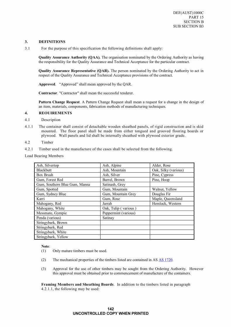
DEF(AUST)1000C
PART 15
SECTION B
SUB SECTION B3
142 UNCONTROLLED COPY WHEN PRINTED
3. DEFINITIONS
3.1 For the purpose of this specification the following definitions shall apply:
Quality Assurance Authority (QAA). The organisation nominated by the Ordering Authority as having
the responsibility for the Quality Assurance and Technical Acceptance for the particular contract.
Quality Assurance Representative (QAR). The person nominated by the Ordering Authority to act in
respect of the Quality Assurance and Technical Acceptance provisions of the contract.
Approved. “Approved” shall mean approved by the QAR.
Contractor. "Contractor" shall mean the successful tenderer.
Pattern Change Request. A Pattern Change Request shall mean a request for a change in the design of
an item, materials, components, fabrication methods of manufacturing techniques.
4. REOUIREMENTS
4.1 Description
4.1.1 The container shall consist of detachable wooden sheathed panels, of rigid construction and is skid
mounted. The floor panel shall be made from either tongued and grooved flooring boards or
plywood. Wall panels and lid shall be internally sheathed with plywood exterior grade.
4.2 Timber
4.2.1 Timber used in the manufacture of the cases shall be selected from the following.
Load Bearing Members
Ash, Silvertop Ash, Alpine Alder, Rose
Blackbutt Ash, Mountain Oak, Silky (various)
Box Brush Ash, Silver Pine, Cypress
Gum, Forest Red Barrel, Brown Pine, Hoop
Gum, Southern Blue Gum, Manna Satinash, Grey
Gum, Spotted Gum, Mountain Walnut, Yellow
Gum, Sydney Blue Gum, Mountain Grey Douglas Fir
Karri Gum, Rose Maple, Queensland
Mahogany, Red Jarrah Hemlock, Western
Mahogany, White Oak, Tulip ( various )
Messmate, Gympie Peppermint (various)
Penda (various) Satinay
Stringybark, Brown
Stringybark, Red
Stringybark, White
Stringybark, Yellow
Note:
(1) Only mature timbers must be used.
(2) The mechanical properties of the timbers listed are contained in AS AS 1720.
(3) Approval for the use of other timbers may be sought from the Ordering Authority. However
this approval must be obtained prior to commencement of manufacture of the containers.
Framing Members and Sheathing Boards. In addition to the timbers listed in paragraph
4.2.1.1, the following may be used:

DEF(AUST)1000C
PART 15
SECTION B
SUB SECTION B3
143 UNCONTROLLED COPY WHEN PRINTED
a. scrub timbers from NSW and Queensland,
b. plantation grown pines, such as Pinus Radiata.
Skids. Mature hardwood species of strength SD 4 as detailed in TABLE Bl, Appendix B to
AS 1720 shall be used.
Plywood. Species of timber in veneer used for the plywood shall be selected from the following
list:
Standard Trade Common
Name
Botanical Name
Softwoods
Bindang Agathis sp.
Dakua Agathis Vitiensis
Kauri Agathis spp.
Pine, Bunya Araucaris biwillii
Pine, hoop Araucaris cunninghamii
Pine, Klinki Araucaria hunsteinii
Pine, radiata Pinus radiata
Pine slash Pinus elliottii
Hardwoods
Alder, blush Sloanea australis
Alder, brown Ackama paniculata
Alder, rose Ackama australiensis
Ash, northern silver Flindersia pubescens
Ash, Queensland silver Flindersia bourjotiana
Birch, white Schizomeria ovata
Butternut, rose Blepharocarya involucrigera
Carabeen, yellow Sloanea woollsii
Coachwood Ceratopetalum apetalum
Maple, Queensland Flindersia brayleyana
Ramin Gonystylus sp.
Silkwood, bolly Cryptocarya oblata
Silkwood, red Palaquium galactroxylum
Sassafras, Northern Doryphora spp.
Sassafras, Southern Atherosperma moschatum
Walnut, yellow Bielschiedia bancroftii
4.2.2 Common Names. Common names, used as a standard in the trade, in this specification, are in
accordance with AS 2543.
4.2.3 Lyctus Susceptibility. Timbers containing sapwood shall not be used unless they are of the
following types:
a. softwood (coniferous, or non-pored timber), hardwood as listed in paragraph 4.2.5 or wood
approved by the Ordering Authority, or
b. sapwood immunised against Lyctus borer attack in accordance with AS 1604 or by any other
method approved by the Ordering Authority.
4.2.4 Timber Treatment Methods. Advice on methods of treatment to immunise timber against Lyctus
borer attack may be obtained from the State Forest Commission CSIRO Division of Building
Research, or any other recognised authority.
4.2.5 Hardwood not Susceptible to Lyctus Borer Attack

DEF(AUST)1000C
PART 15
SECTION B
SUB SECTION B3
144 UNCONTROLLED COPY WHEN PRINTED
Adler, rose Gum, salmon Penda, red
Ash, alpine Gum, scribbly IPenda, brown
Ash, mountain Hardwood, Johnstone River Sassafras
Ash, silvertop Satinay
Blackbutt Iron Bark (various) Stringybark (brown)
Box, brush Jarrah Stringybark (white)
Gum, forest-red Karri Stringybark
Gum, Grey Mahogany, white
Gum, rose Messmate, Gympie
4.3 Timber Quality
4.3.1 The quality of timber, used in the manufacture of the containers shall be as follows.
Load Bearing Members. Each bearer shall be cut from mature timber which is sound, well sawn,
dressed all round and free from heart, shakes, unsound knots, rot, wane and end splits. The
following defects are permitted provided that they do not interfere with bolting or nailing, and are
not grouped to reduce the section of the piece by more than 25%.
Tight Knots. Sound tight knots shall have a diameter less than one quarter of the width of the
piece in which they occur, and located not less than 100 mm from the anchoring bolts or the end
of the bearer.
Gum Veins. Tight gum veins shall not exceed 3 mm in width or a length of 150 mm per 300 mm by 300 mm or equivalent area of the member's face.
Slope of Grain. 20 mm in 300 mm Slope of grain shall not exceed or a ratio of 1:15.
Sapwood. Refer to paragraph 4.2.3.
Framing Members and Sheathing Boards. Each piece of timber and sheathing board shall be
sound, well sawn, dressed all round and consist of either sheet plywood or tongued and grooved
for sheathing boards and free from brittle heart and shakes. The following defects are per mitted
provided that, in the case of a framing member, at least one half of its width, on either face, at any
point in its length, shall be free of defects, and that, in the case of framing members, and
sheathing boards, allowable defects shall not interfere with the prescribed bolting and nailing.
Tight Knots. Sound tight knots shall have a diameter less than one third of the width of the piece
in which they occur, and located no less than 30 mm from either end.
Unsound Knots. Unsound knots, knot holes and grub holes, shall be less than one quarter of the
framing piece width, in which they occur, or less than 15 mm in diameter for sheathing boards,
and located not less than 50 mm from either end for both instances.
Slopes of Grain. The slopes of grain shall not be greater than 25 mm in 300 mm or a ratio of
1:12.
Gum Veins. Tight gum veins are permitted.
Gum Pockets. Gum pockets shall not exceed 300 mm in length and 15 mm wide in the radial
direction. These gum pockets may occur not more than one in any 2 length piece.
Want and Wane. Want and wane shall not exceed one eighth of the cross sectional area of the
member.
Decay. Decay shall be permitted in the form of surface attack only.
Pin Holes. Scattered pinholes only may be permitted in any member.
Pith. Pith is permitted in one face or one edge of softwood framing timbers only.
Skids or Runners. Skids or runners shall be as follows:
a. They shall be made from hardwood timber with the bottom edge dressed.
b. They shall not protrude beyond the outer edges of the containers.
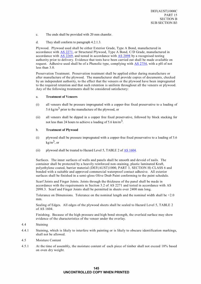
DEF(AUST)1000C
PART 15
SECTION B
SUB SECTION B3
145 UNCONTROLLED COPY WHEN PRINTED
c. The ends shall be provided with 20 mm chamfer.
d. They shall conform to paragraph 4.2.1.3.
Plywood. Plywood used shall be either Exterior Grade, Type A Bond, manufactured in
accordance with AS 2271, or Structural Plywood, Type A Bond, C/D Grade, manufactured in
accordance with AS 2269, and tested in accordance with AS 2098 by a recognised testing
authority prior to delivery. Evidence that tests have been carried out shall be made available on
request. Adhesive used shall be of a Phenolic type, complying with AS 2754, with a pH of not
less than 3.0.
Preservation Treatment. Preservation treatment shall be applied either during manufacture or
after manufacture of the plywood. The manufacturer shall provide copies of documents, checked
by an independent authority, to the effect that the veneers or the plywood have been impregnated
to the required retention and that such retention is uniform throughout all the veneers or plywood. Any of the following treatments shall be considered satisfactory:
a. Treatment of Veneers
(i) all veneers shall be pressure impregnated with a copper-free fixed preservative to a loading of
5.6 kg/m3 prior to the manufacture of the plywood, or
(ii) all veneers shall be dipped in a copper free fixed preservative, followed by block stacking for
not less than 24 hours to achieve a loading of 5.6 km/m3.
b. Treatment of Plywood
(i) plywood shall be pressure impregnated with a copper-free fixed preservative to a loading of 5.6
kg/m3, or
(ii) plywood shall be treated to Hazard Level 5, TABLE 2 of AS 1604.
Surfaces. The inner surfaces of walls and panels shall be smooth and devoid of nails. The
container shall be protected by a heavily reinforced non-staining, plastic laminated Kraft,
polyethylene coated, barrier material (DEF(AUST)1000, PART 3, SECTION H) CLASS 6 and
bonded with a suitable and approved commercial waterproof contact adhesive. All exterior
surfaces shall be finished in a semi-gloss Olive Drab Paint conforming to the paint schedule.
Scarf Joints and Finger Joints. Joints through the thickness of the panel shall be made in
accordance with the requirements in Section 3.2 of AS 2271 and tested in accordance with AS
2098.3. Scarf and Finger Joints shall be permitted in sheets over 2400 mm long.
Tolerance on Dimensions. Tolerance on the nominal length and the nominal width shall be +2.0
mm.
Sealing of Edges. All edges of the plywood sheets shall be sealed to Hazard Level 5, TABLE 2
of AS 1604.
Finishing. Because of the high pressure and high bond strength, the overlaid surface may show
evidence of the characteristics of the veneer under the overlay.
4.4 Staining
4.4.1 Staining, which is likely to interfere with painting or is likely to obscure identification markings,
shall not be allowed.
4.5 Moisture Content
4.5.1 At the time of assembly, the moisture content of each piece of timber shall not exceed 18% based
on oven dry weight.

DEF(AUST)1000C
PART 15
SECTION B
SUB SECTION B3
146 UNCONTROLLED COPY WHEN PRINTED
4.6 Dimensions
4.6.1 Width and thickness dimensions of all timbers are nominal sizes. The minimum acceptable
dimensions shall be as shown in TABLE 56 of ANNEX A, unless detailed in the Tender Schedule.
4.7 Bolts, Nuts and Washers
4.7.1 Bolts, nuts and washers shall be supplied and fitted as follows:
a. All bolts shall be complete with nuts and washers shall be zinc coated.
b. Where required, nuts shall be of the self-locking type.
c. Bolt clearance holes in timber shall not be more than 2 mm larger than the bolt diameter.
d. All bolts shall be greased prior to insertion in the holes and tightening of the nuts.
e. Clamping bolts for Hinge and Top Hat Closures shall be high tensile steel.
4.8 Nails
4.8.1 Nails shall be of the drive screw pallet nail or resin (cement) coated typed. The size, placement
and quantity shall be in accordance with ANNEX B and FIGURE 5 of ANNEX C.
4.9 Size of Case Members
4.9.1 Load Bearing and Base Framing Members. All load bearing and base framing members shall be
of the same thickness as that for the member bearing with the greatest load, and as determined
from TABLE 57 of ANNEX A.
4.9.2 Framing Members. All framing members used for the side, end and top panels shall be of the
same size and shall be as follows:
a. For containers up to 1135 kg net mass or with a base area of up to 3m2, use 75 mm by 50 mm.
b. For containers up to 4.5 t net mass or with a base area of over 3 m2, use 100 mm by 50 mm.
c. For containers over 4.5 t net mass the sizes will be detailed in the Tender Schedule as a separate
item.
4.9.3 Skids or Runners. All skids and runners used shall be of the same size and shall be a minimum of
100 mm in height to allow for forklift loading. The sizes shall be as follows:
a. for containers up to 1135 kg gross mass, 100 mm by 75 mm,
b. for containers up to 3 t gross mass, 125 mm by 75 mm,
c. for containers up to 4.5 t gross mass, 150 mm by 100 mm, and
d. for containers over 4.5 t gross mass, the sizes will be detailed in the Tender Schedule as a
separate item.
4.9.4 Sheathing. Sheathing boards used for the floors shall be either plywood sheets 20 mm thick or
boards of a finished size not less than 95 mm wide by 20 mm thick. The plywood sheathing used
for the walls and lid shall be 10 mm nominal thickness with a tolerance of + 0.5 mm.
4.10 Method of Construction of Container
4.10.1 Style. The panels of the container shall be of styles and maximum outside dimensions in accordance with TABLE 54 of ANNEX A and as illustrated in FIGURES 1, 2, 3 and 4 of ANNEX
C. The method used in the construction of the container shall be in accordance with TABLE 52of
ANNEX A. Where adequate support or separation of the contents within the container is
necessary or where sling straps are used, members additional to those of the basic design shall be
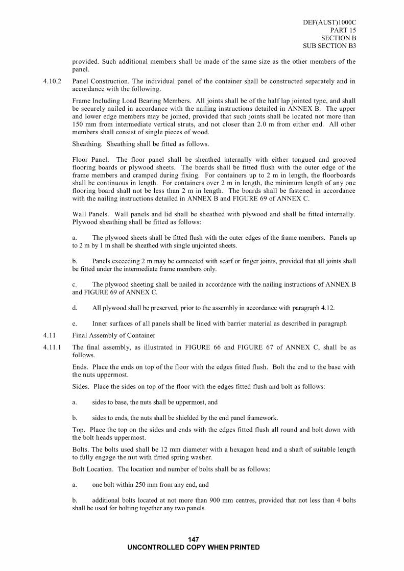
DEF(AUST)1000C
PART 15
SECTION B
SUB SECTION B3
147 UNCONTROLLED COPY WHEN PRINTED
provided. Such additional members shall be made of the same size as the other members of the
panel.
4.10.2 Panel Construction. The individual panel of the container shall be constructed separately and in accordance with the following.
Frame Including Load Bearing Members. All joints shall be of the half lap jointed type, and shall
be securely nailed in accordance with the nailing instructions detailed in ANNEX B. The upper
and lower edge members may be joined, provided that such joints shall be located not more than
150 mm from intermediate vertical struts, and not closer than 2.0 m from either end. All other
members shall consist of single pieces of wood.
Sheathing. Sheathing shall be fitted as follows.
Floor Panel. The floor panel shall be sheathed internally with either tongued and grooved
flooring boards or plywood sheets. The boards shall be fitted flush with the outer edge of the
frame members and cramped during fixing. For containers up to 2 m in length, the floorboards shall be continuous in length. For containers over 2 m in length, the minimum length of any one
flooring board shall not be less than 2 m in length. The boards shall be fastened in accordance
with the nailing instructions detailed in ANNEX B and FIGURE 69 of ANNEX C.
Wall Panels. Wall panels and lid shall be sheathed with plywood and shall be fitted internally.
Plywood sheathing shall be fitted as follows:
a. The plywood sheets shall be fitted flush with the outer edges of the frame members. Panels up
to 2 m by 1 m shall be sheathed with single unjointed sheets.
b. Panels exceeding 2 m may be connected with scarf or finger joints, provided that all joints shall
be fitted under the intermediate frame members only.
c. The plywood sheeting shall be nailed in accordance with the nailing instructions of ANNEX B
and FIGURE 69 of ANNEX C.
d. All plywood shall be preserved, prior to the assembly in accordance with paragraph 4.12.
e. Inner surfaces of all panels shall be lined with barrier material as described in paragraph
4.11 Final Assembly of Container
4.11.1 The final assembly, as illustrated in FIGURE 66 and FIGURE 67 of ANNEX C, shall be as
follows.
Ends. Place the ends on top of the floor with the edges fitted flush. Bolt the end to the base with the nuts uppermost.
Sides. Place the sides on top of the floor with the edges fitted flush and bolt as follows:
a. sides to base, the nuts shall be uppermost, and
b. sides to ends, the nuts shall be shielded by the end panel framework.
Top. Place the top on the sides and ends with the edges fitted flush all round and bolt down with
the bolt heads uppermost.
Bolts. The bolts used shall be 12 mm diameter with a hexagon head and a shaft of suitable length
to fully engage the nut with fitted spring washer.
Bolt Location. The location and number of bolts shall be as follows:
a. one bolt within 250 mm from any end, and
b. additional bolts located at not more than 900 mm centres, provided that not less than 4 bolts
shall be used for bolting together any two panels.
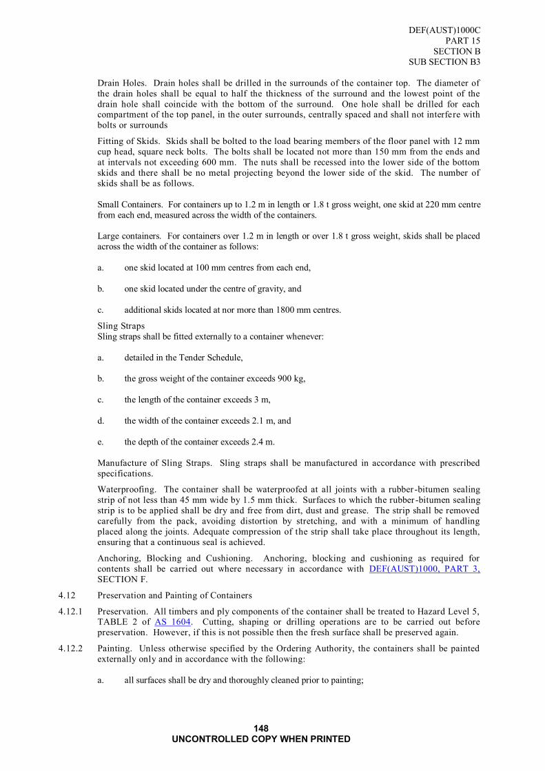
DEF(AUST)1000C
PART 15
SECTION B
SUB SECTION B3
148 UNCONTROLLED COPY WHEN PRINTED
Drain Holes. Drain holes shall be drilled in the surrounds of the container top. The diameter of
the drain holes shall be equal to half the thickness of the surround and the lowest point of the
drain hole shall coincide with the bottom of the surround. One hole shall be drilled for each compartment of the top panel, in the outer surrounds, centrally spaced and shall not interfere with
bolts or surrounds
Fitting of Skids. Skids shall be bolted to the load bearing members of the floor panel with 12 mm
cup head, square neck bolts. The bolts shall be located not more than 150 mm from the ends and
at intervals not exceeding 600 mm. The nuts shall be recessed into the lower side of the bottom
skids and there shall be no metal projecting beyond the lower side of the skid. The number of
skids shall be as follows.
Small Containers. For containers up to 1.2 m in length or 1.8 t gross weight, one skid at 220 mm centre
from each end, measured across the width of the containers.
Large containers. For containers over 1.2 m in length or over 1.8 t gross weight, skids shall be placed
across the width of the container as follows:
a. one skid located at 100 mm centres from each end,
b. one skid located under the centre of gravity, and
c. additional skids located at nor more than 1800 mm centres.
Sling Straps
Sling straps shall be fitted externally to a container whenever:
a. detailed in the Tender Schedule,
b. the gross weight of the container exceeds 900 kg,
c. the length of the container exceeds 3 m,
d. the width of the container exceeds 2.1 m, and
e. the depth of the container exceeds 2.4 m.
Manufacture of Sling Straps. Sling straps shall be manufactured in accordance with prescribed
specifications.
Waterproofing. The container shall be waterproofed at all joints with a rubber -bitumen sealing
strip of not less than 45 mm wide by 1.5 mm thick. Surfaces to which the rubber -bitumen sealing
strip is to be applied shall be dry and free from dirt, dust and grease. The strip shall be removed
carefully from the pack, avoiding distortion by stretching, and with a minimum of handling
placed along the joints. Adequate compression of the strip shall take place throughout its length,
ensuring that a continuous seal is achieved.
Anchoring, Blocking and Cushioning. Anchoring, blocking and cushioning as required for
contents shall be carried out where necessary in accordance with DEF(AUST)1000, PART 3,
SECTION F.
4.12 Preservation and Painting of Containers
4.12.1 Preservation. All timbers and ply components of the container shall be treated to Hazard Level 5, TABLE 2 of AS 1604. Cutting, shaping or drilling operations are to be carried out before
preservation. However, if this is not possible then the fresh surface shall be preserved again.
4.12.2 Painting. Unless otherwise specified by the Ordering Authority, the containers shall be painted
externally only and in accordance with the following:
a. all surfaces shall be dry and thoroughly cleaned prior to painting;
DEF(AUST)1000C
PART 15
SECTION B
SUB SECTION B3
149 UNCONTROLLED COPY WHEN PRINTED
b. one primer coat;
c. one undercoat;
d. two finishing coats of which the paint used shall be as per APAS painting schedule
e. all workmanship shall be to the requirements of the QAA.
4.13 Centre of Balance
4.13.1 Where sling straps are not fitted, the centre of gravity of the packed containers shall be indicated
by a painted or stencilled black strip, 10 mm wide, on each side of the container and placed on the
upper and lower edges of the sides. The words "Centre of Balance" shall be stencilled in black
letters at least 25 mm high, adjacent to the strips.
4.14 Identification and Markings
4.14.1 Identification and markings shall be in accordance with DEF(AUST)1000, PART 5. When
nominated in the Contract Acceptance and Purchase Order (CAPO), the Contract Number shall
also be included. Warning and cautionary markings in accordance with DEF(AUST)1000, PART
5 shall be applied as follows:
a. Use No Hooks or Grabs,
b. This Side Up,
c. Open This Side for Inspection,
d. Open This Side for Identification (where applicable),
e. Technical Manual This Container (where more than one container is involved), and
f. Other markings as required.
4.15 Alternative Packing Methods
4.15.1 The tenderers shall submit costs for wooden containers in accordance with this specification.
Alternative packaging methods including the use of aluminium, or steel breakdown containers
may be proposed by the tenderer and may be considered for acceptance. Particulars of alternative
packaging and costs shall be detailed in the tender schedule as a separate item. Where an
alternative is tendered, proof of strength equivalent to timber containers shall be submitted.
4.16 Tests
4.16.1 The Contractor shall be responsible for carrying out all tests required by the Ordering Authority
to ensure that the markings and materials are in accordance with this specification.
5. QUALITY ASSURANCE PROVISIONS
5.1 The Contractor shall maintain effective control of the quality of supplies and/or services
(including subcontracts), provide test facilities and perform all examinations and tests stated in
the contract to demonstrate conformance of supplies and/or services to the technical requirements
of the contract and shall offer for acceptance only supplies and/or services that conform to these
requirements.
5.2 The Contractor shall be responsible for the provision of objective evidence demonstrating that the
controls applied and inspections carried out are effective.
5.3 The Ordering Authority is the Quality Assurance Authority and reserves the right to perform any
examinations or tests to ensure that supplies and/or services conform to the technical
requirements of the contract.
5.4 Acceptance of all supplies and services shall be subject to agreement by the Ordering Authority
that the quality requirements have been fulfilled. The Quality Assurance Authority reserves the

DEF(AUST)1000C
PART 15
SECTION B
SUB SECTION B3
150 UNCONTROLLED COPY WHEN PRINTED
right to reject any supplies which fail to meet the technical requirements of this contract.
5.5 The Request for Tender and contract shall nominate the Ordering Authority, quality assurance and
acceptance provisions and the requirements for Contractor's quality control.
6. NOTES
6.1 Contractual Information
6.1.1 The official tenders invitation and contract shall nominate the Quality Assurance Authority, the
conditions of inspection and the requirements for Contractor's Quality Control.
6.2 Intended Use
6.2.1 The containers are intended to be used as reusable containers for domestic and overseas transport.
They shall provide full standard protection as an outer container, and shall be designed to
withstand heavy superimposed loads in the stacking of containers.
6.3 Ordering Data. All purchasing documents, orders and contracts may need to specify:
a. title, number, date and amendment status of this Specification;
b. number required;
c. box style and external dimensions;
d. the Quality Assurance Authority, the conditions of inspection and requirements for contractor‟s
Quality Control (paragraph 5);
e. packaging requirements (paragraph 4.15); and
f. marking of packs (paragraph 4.14).
ANNEX A
TABLE 54 SELECTION OF PANEL STYLES
Outside Dimensions (mm) Panel Style
Length Width Depth Base Top Sides Ends
Up to 1200 Up to 1200 Up to 1200 5 1 1 1
Over 1200 Up to 1200 Up to 1200 6 3 3 1 Over 1200 Over 1200 Up to 1200 7 7 3 1
Up to 1200 Up to 1200 Over 1200 5 1 2 2
Over 1200 Up to 1200 Over 1200 6 3 4 4
Over 1200 Over 1200 Over 1200 7 7 7 7

DEF(AUST)1000C
PART 15
SECTION B
SUB SECTION B3
ANNEX A
151 UNCONTROLLED COPY WHEN PRINTED
TABLE 55 SUMMARY OF PANEL STYLES
Style Length Width or Depth Remarks
1 Up to 1200 Up to 1200 One diagonal brace.
2 Up to 1200 Over 1200 Intermediate members symmetrically
spaced at not more than 750 mm centres.
3 Over 1200 Up to 1200 Intermediate members symmetrically
spaced at not more than 900 mm centres
4 Over 1200 Over 1200 Intermediate members symmetrically
spaced at not more than 900 mm centres.
5 Up to 1200 Up to 1200 One intermediate member located at 100
mm centres from each end.
6 Over 1200 Up to 1200 One intermediate member located at 100 mm centres from each end. Other
intermediate members symmetrically
spaced at not more than 900 mm centres.
7 Over 1200 Over 1200 One intermediate member located at 100
mm centres from each end. Other
intermediate members symmetrically
spaced at not more than 900 mm centres.
For illustrations see FIGURES 1, 2, 3 and 4 of ANNEX C.
TABLE 56 DIMENSIONS
Nominal Dimension
Minimum Acceptable Finished Dimensions
(mm) Timber 50 mm
Thick or Less
Timber More Than
50 mm Thick
25 20.5
32 28.5
38 35
50 44.5
75 70 73
100 95 98
125 117.5 120
150 143 146
175 168 171 200 190 196
225 215 222
250 241 247
300 292 298
TABLE 57 SIZE OF LOAD BEARERS
Load per Span (mm)*
Bearer up to ..X.. kg
(X)
300 400 600 750 900 1050 1200
200 75 x 50 75 x 50 75 x 50 75 x 50 75 x 50 100 x 50 75 x 50
300 75 x 50 75 x 50 100 x 50 100 x 50 75 x 75 75 x 75 75 x 75
400 75 x 50 75 x 50 100 x 50 75 x 75 75 x 75 75 x 75 100 x 75
500 75 x 50 75 x 50 100 x 50 75 x 75 75 x 75 100 x 75 100 x 75
600 75 x 50 75 x 50 100 x 50 75 x 75 100 x 75 100 x 75 100 x 75
700 100 x 50 100 x 50 75 x 75 75 x 75 100 x 75 100 x 75 125 x 75
* The size of the Bearer is always specified as width by thickness
DEF(AUST)1000C
PART 15
SECTION B
SUB SECTION B3
ANNEX A
152 UNCONTROLLED COPY WHEN PRINTED
Blank Page

DEF(AUST)1000C
PART 15
SECTION B
SUB SECTION B3
ANNEX B
153 UNCONTROLLED COPY WHEN PRINTED
ANNEX B
NAILING INSTRUCTION
B1. The following rules shall be followed to determine the size, placement and quantity of nails:
B.1.1 Length
a. When nailing together flat pieces of timber of which the combined thickness exceeds 50 mm,
or when the flat face of one or more pieces are nailed to the edge or end face, nails shall be long enough to provide minimum penetration into the second board 2/3 of the nail length, in softwoods, and ½ of the
nail length in hardwoods.
b. When nailing flat pieces of 25 mm thickness together, nails 65 mm long shall be used, and
shall be clinched across the grain.
B1.2 Gauge. The minimum diameter shall be 2.5 mm for 65 mm long nails, 3.76 mm for 75 mm long nails
and 4.5 mm for 100 mm long nails. Nails used with plywood shall be flat head.
B1.3 Placement
a. Nails of 2.8 mm diameter and smaller shall be driven not less than 15 mm from ends or side edges of any board. Nails 3.75 mm diameter and larger shall be driven not less than 25 mm from the
ends or side edges of any board.
b. Nails shall be driven in rows and staggered slightly within the row so that adjacent nails are
not in the same grain. Not less than three nails shall be used for nailing together any two members.
c. When attaching two members, having parallel grains, one row of nails shall be used for widths
up to and including 50 mm, two rows for widths greater than 50 mm but not exceeding 150 mm and
three rows for widths exceeding 150 mm.
d. When two members of respectively 25 mm and 50 mm thick timber are nailed together, nails shall be located at least 25 mm from the edges and not more than 450 mm apart in the same rows. The
number of rows shall be as in c(iii). The thinner piece shall contain the nails heads.
e. When two members of 50 mm thick timber are nailed together, the nails shall be located at
least 25 mm from the edges, and not more than 450 mm in the same row. The number of rows shall be
as in c(iii). Adjacent nails in each row shall be driven from opposite sides of the timber pieces.
B1.4 General
a. All adjacent case members shall be securely nailed to each other.
b. Nails shall be driven through the thinner into the thicker member, whenever possible.
c. Nails shall be cleanly driven, either by hand or machine.
d. Neither the head nor the point of any nail shall project above the surface of the wood.
e. When nailing flat faces of two pieces of timber together protruding nails shall be clinched.
f. If splitting of the timber occurs, causing it to weaken the structure, holes, not less than 80% of
the nail diameter and not more than 90% of the nail diameter shall be drilled in the timber for each nail.
g. The nailing of plywood shall be in two staggered rows as illustrated in FIGURE 69 NAILING PATTERN of ANNEX C.
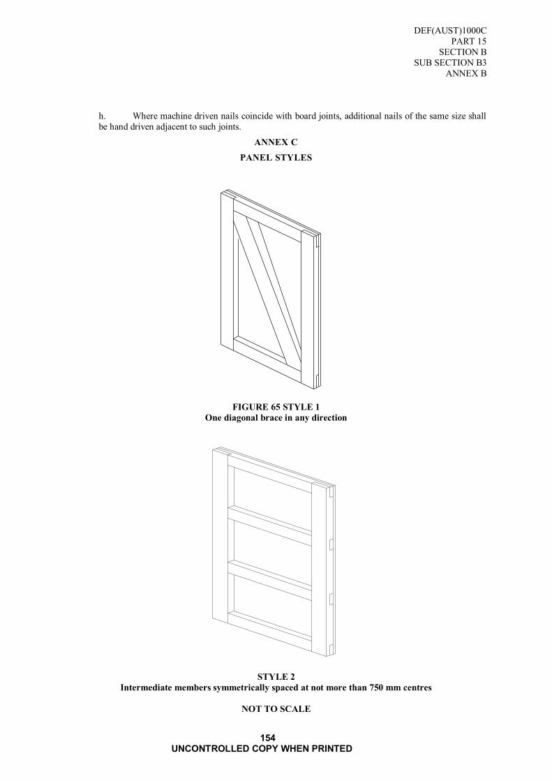
DEF(AUST)1000C
PART 15
SECTION B
SUB SECTION B3
ANNEX B
154 UNCONTROLLED COPY WHEN PRINTED
h. Where machine driven nails coincide with board joints, additional nails of the same size shall
be hand driven adjacent to such joints.
ANNEX C
PANEL STYLES
FIGURE 65 STYLE 1
One diagonal brace in any direction
STYLE 2
Intermediate members symmetrically spaced at not more than 750 mm centres
NOT TO SCALE

DEF(AUST)1000C
PART 15
SECTION B
SUB SECTION B3
ANNEX B
155 UNCONTROLLED COPY WHEN PRINTED
FIGURE 66 PANEL STYLES
STYLE 3
Intermediate members symmetrically spaced at not more than 900 mm centres
STYLE 4
Intermediate members symmetrically spaced at not more than 900 mm centres. Diagonal bracing meets
an intermediate member at the centre of the panels
NOT TO SCALE

DEF(AUST)1000C
PART 15
SECTION B
SUB SECTION B3
ANNEX B
156 UNCONTROLLED COPY WHEN PRINTED
FIGURE 67 PANEL STYLES
STYLE 5
Intermediate bearers 100 mm centres from each end. Longitudinal
frame member at not more than 600 mm centre
STYLE 6
Intermediate bearers 100 mm centres from each end. Other bearers at not more
than 900 mm centres. Longitudinal frame members at not more than 600 mm centres
NOT TO SCALE

DEF(AUST)1000C
PART 15
SECTION B
SUB SECTION B3
ANNEX B
157 UNCONTROLLED COPY WHEN PRINTED
FIGURE 68 PANEL STYLES
STYLE 7
Intermediate bearers 100 mm centres from each end. Other bearers at not more
than 900 mm centres longitudinal frame members at not more than 600 mm centres

DEF(AUST)1000C
PART 15
SECTION B
SUB SECTION B3
ANNEX B
158 UNCONTROLLED COPY WHEN PRINTED
FIGURE 69 NAILING PATTERN

DEF(AUST)1000C
PART 15
SECTION B
SUB SECTION B3
ANNEX B
159 UNCONTROLLED COPY WHEN PRINTED
FIGURE 70 CASE DESIGN
NOT TO SCALE

DEF(AUST)1000C
PART 15
SECTION B
SUB SECTION B3
ANNEX B
160 UNCONTROLLED COPY WHEN PRINTED
FIGURE 71 CASE DESIGN
NOT TO SCALE

DEF(AUST)1000C
PART 15
SECTION B
SUB SECTION B4
161 UNCONTROLLED COPY WHEN PRINTED
SUB SECTION B4: CRATES SHIPPING (WOOD)
1. SCOPE
1.1 This specification details the requirements for the manufacture of crates used for the delivery of
equipment and supply of crates, wood, open and sheathed.
1.2 Classification
1.2.1 The crates shall be supplied in the following classes and styles:
Nailing Instruction DATA SHEET No.1
Class 1 Crates, Shipping (Wood Open)
Style 1 - Up to 50 kg gross DATA SHEET No. 2
Style 2 - Up to 100 kg gross DATA SHEET No. 3
Style 3 - Up to 200 kg gross DATA SHEET No. 4
Style 4 - Up to 500 kg gross DATA SHEET No. 5
Style 5 - Up to 1000 kg gross DATA SHEET No. 6
Note: The capacity of each Class 1 crate is quoted as ....... kg gross (crate and contents). These
FIGUREs should be used with discretion, as a guide only, because a standard method of determining
mass capacity is not available.
Class 2 Crates, Shipping (Wood, Bolted and Sheathed)
Style 1 - Up to 1100 mm long and up to 1100 mm deep DATA SHEET No. 7
Style 2 - Over 1100 mm long and up to 1100 mm deep DATA SHEET No. 8
Style 3 - Over 1100 mm long and over 1100 mm deep DATA SHEET No. 9
2. APPLICABLE DOCUMENTS
2.1 Reference may be necessary to the latest issue of the following documents:
Australian Department of Defence
DEF(AUST)5047 - Australian Government Ownership Symbol, Dimensions and Use
This document is available from the sources shown inside the back cover.
(Refer Request for Documents Page)
Standards Australia
AS 1080 - Methods of Test for Timber Part 1
AS 1199 - Sampling Procedures and TABLEs for Inspection by Attributes
AS 1399 - Guide to AS 1199, Sampling Procedures and TABLEs for Inspection by Attributes
AS 1604 - Preservative Treatment for Sawn Timber, Veneer and Plywood
AS 1607 - Water-repellent solutions for The Treatment of Timber, Joinery and Other Timber Products
AS 1720 - Rules for the Use of Timber in Structures
AS 1859 - Flat Pressed Particle board
AS 2271 - Plywood and Blockboard for Exterior Use
DEF(AUST)1000C
PART 15
SECTION B
SUB SECTION B4
162 UNCONTROLLED COPY WHEN PRINTED
AS 2334 - Steel Nails - Metric Series
AS 2458 - Hardboard
AS 2490 - Sampling Procedures and Charts for Inspection by Variables for Percent Defect.
AS 2754 - Adhesives for timber and Timber Products Part 1 Adhesives for Plywood Manufacture
AS 2878 - Timber - Classification Into Strength Groups
Details of where copies of Australian Standard may be obtained from are displayed at : SAI Global
For Defence personnel only: Standards Australia documents are available from the
Defence Library Service at the following URL: http://library.dcb.defence.gov.au/standards/standards.nsf
Australian Paint Approval Scheme
The following specifications are available at the following URL: http://www.apas.gov.au/
APAS 0006/1 Army Olive Drab flat enamel (equipment)
APAS 0006/2 Army Olive Drab low gloss enamel (equipment)
APAS 0181 - Solvent borne wood primer (buildings)
3. DEFINITIONS
3.1 For the purpose of this specification the following definitions shall apply:
Batten. Reinforcing member attached, at right angles, to the grain to a wood panel box to a wood
barrel head, or to the face of a wire bound box or crate.
Bearer. Pieces of timber secured at right angles to the longest dimension of the container to facilitate
lifting by mechanical handling device.
Brace Made of either metal or timber and fixed at an angle of less than 90° across the crate in order to
support items within a container, to prevent damage through movement and to distribute mass on all
faces of the container.
Cleat. 1. Pieces of material such as wood or metal attached to a structural body to secure, strengthen, furnish a grip etc.
2. In wire bound boxes, the piece of timber forming the framework to which face boards are
fastened.
Clinch. After nailing, to bend or turn over the protruding points so those nails will hold fast.
Crate. A rigid shipping container of framed construction joined together with nails, bolts or any
equivalent method of fastening. The framework may or may not be enclosed with sheathing.
a. Crate Assembled. A crate with lid assembled and ready for use.
b. Crate Open. A crate with exposed frame members.
c. Crate Sheathed. A crate having the frame members completely covered with sheathing
boards or material.

DEF(AUST)1000C
PART 15
SECTION B
SUB SECTION B4
163 UNCONTROLLED COPY WHEN PRINTED
d. Crate Unassembled. An assembly of end, slide, top and bottom components ready to form into an
assembled crate.
Drain Channels. Spaces or channels in the underside of the framing timber of the lid of the
sheathed crate to allow water or condensate to escape.
Framework. The end, side, top and bottom rails, battens and girth battens and, where
required, diagonal braces of a container.
Oriented Strand Board (OSB). Constructed by using long strands of wood chips aligned in layers
and bonded with phenolic resin under extreme pressure. The Physical Properties are:
Bending Strength
Modulus of Rupture (MOR) Longitudinal 30 Mpa
Transverse 23 Mpa
Stiffness
Modulus of Elasticity (MOE)
Longitudinal 4.0 GPa
Transverse 2.9 GPa
Density 700 kg/m3 min
730 kg/m3 max
Moisture Content 5 per cent min
10 per cent max
Shooks. Cut to size components of an unassembled wooden case or crate.
4. REQUIREMENTS
4.1 General
4.1.1 The technical requirements for each crate are contained in separate data sheets appended to this
specification. The data sheets shall be read in conjunction with the other requirements of this
specification.
4.2 Materials
4.2.1 Timber
Species. The species of timber used shall have strength properties not less than S6 strength group (as determined by AS 2878). The stress grade shall be not less than F7 and shall conform
to the standard listed in AS 1720 when graded according to the relevant structural timber
grading suitable timbers are listed in TABLE I.
TABLE 58 SUITABLE TIMBERS
Hardwood
Softwood
OB, Hardwood PINE, Hoop
(Ordinary Building Grade) PINE, Radiata
PINE, White Cypress
DOUGLASFIR (Oregon)
Reclaimed Timber. If reclaimed timber is used, the timber shall meet all the requirements of
this specification. Timber containing bolts, nails, or screws, or containing bolt, nail or screw
holes shall not be used.
Moisture Content. At the time of delivery the moisture content within any piece sold as
"seasoned" shall be not less than 10 per cent or more than 18 per cent. The moisture content of
the timber shall be determined in accordance with AS 1080 Part I. In the event of dispute as to

DEF(AUST)1000C
PART 15
SECTION B
SUB SECTION B4
164 UNCONTROLLED COPY WHEN PRINTED
the moisture content, it shall be determined by the oven- drying method described in Section 2
of AS 1080 Part 1.
Staining. Staining that would adversely affect the subsequent markings of the box shall not be permitted on the external surface.
Timber Surface. Unless otherwise specified the timber shall be fine sawn on all faces.
4.2.2 Load Bearing Members
Each bearer shall be cut from mature timber which is sound, well sawn and free from heart,
shakes, unsound knots, rot, wane and end splits and rated as standard grade SAA standards.
4.2.3 Framing Members
Each piece of framing timber shall be sound, well sawn and free from brittle heart and shakes.
With a rating of select grade from SAA standards.
4.2.4 Sheathing
The sheathing of Class 2 Crates, (floor, walls and top) and flooring for Class I Crates where
specified. Shall be selected from:
a. Flat Pressed Particle Board to .AS l859
b. Hardboard (Tempered grade) to AS 2458
c. Ply wood to AS 2271, bonded with type A Bond to AS 2754.1
d. Oriented Strand Board
4.2.5 Fastenings
All fastenings shall be treated against corrosion, such as galvanised hot dip or equivalent type of
treatment. Crates shall be constructed and assembled with staples or flat head nails in
accordance with AS 2334 and bolts where specified. The bolts shall be either carriage or
hexagonal head type. A galvanised washer shall be fitted behind each nut and under the head if
hexagon bolts are used.
4.3 Preservation and Painting
4.3.1 When specified, hardwood subject to lyctus attack shall be treated in accordance with AS 1604
or by any method that equates to that standard. The method for detection of susceptible
sapwood is given in Appendix E of AS 1604.
4.3.2 All timber and ply components of Class 2 crates shall be treated according to AS 1607 with Composition B. Copper naphthenate for containers not intended to be used in foodstuff,
drinking water or clothing. Timber and ply components that are likely to come into contact with
foodstuffs, drinking water and clothing shall be treated with composition E-Solubilized
copper-8-Hydroxyquinolinate.
Note: Insecticides must not be used on timber intended to be used in contact with food stuffs or
drinking water.
4.3.3 Painting. When specified by the Procurement Authority, the crate shall be painted in
accordance with the following:
a. All surfaces shall be dry and thoroughly cleaned prior to painting.
b. Painting schedule
RAAF as required.
NAVY as required.

DEF(AUST)1000C
PART 15
SECTION B
SUB SECTION B4
165 UNCONTROLLED COPY WHEN PRINTED
4.4 Strapping
4.4.1 Strapping shall conform to DEF(AUST)1000, PART 3, SECTION K, ANNEX A. If type 1 flat
steel type is used the minimum size shall be 16 mm by 0.46 mm thick.
4.4.2 The strapping shall form continuous single bands around the crate and shall be fastened in an
approved manner using seal, seal-less joint or welding. The strapping shall be applied at right
angles to the edges of the crate and shall be drawn tight, so as to sink into the wood at the edges
and shall be fastened by a minimum of two cement coated nails to each face of the crate to
prevent any slipping.
4.4.3 The number of bands shall coincide with the number of girth battens.
4.5 Corner and Edge Strapping
4.5.1 Strapping shall be of 19 mm by 0.550 mm thick 'nail on' type steel, approximately 300 mm long
and shall be fastened by a minimum of two cement coated nails to each face of the crate.
4.6 Sizes of Crate Members
4.6.1 The sizes of members for each style of crate shall be as specified in TABLE 59 All load-bearing members shall be of the same thickness, which shall be that for the member bearing the
greatest load, as determined from TABLE II.
TABLE 59 SIZES OF FRAME WORK MEMBERS
Load per
bearer
* SPAN (mm)
up to X
(kg)
(X)
300 450 600 750 900 1050 1200
25 50x25 50x25 50x25 75x25 75x25 125x25 75x50
50 50x25 50x25 75x25 125x25 75x50 75x50 75x50
100 50x25 100x25 75x50 75x50 75x50 75x50 75x50
150 75x25 125x25 75x50 75x50 75x50 75x50 100x50
200 75x25 75x50 75x50 75x50 75x50 100x50 75x75
300 125x25 75x50 75x50 75x50 100x50 75x75 75x75
400 75x50 75x50 75x50 100x50 75x75 75x75 100x75
500 75x50 75x50 75x50 75x75 75x75 75x75 100x75
600 75x50 75x50 100x50 75x75 75x75 75x75 100x75
700 75x50 75x50 100x50 75x75 75x75 l00x75 125x75
* Distance between inside edges of base frame members.
4.7 Construction
4.7.1 General. Nails and staples shall be driven so that neither the head nor the crown protrudes above the timber. Slight overdriving shall be permitted provided this does not exceed more than
one-eight the thickness of the timber.
Staples. Staples shall be driven at approximately 30 degree angle to the general grain
direction. In general the requirements for nailing shall apply to stapling.
Nailing. Hand driven nails shall be driven at slightly opposing angles of 70-80 degrees to each
other. Nails shall be cleanly driven from the outside except when affixing bottom bearers where the
nails shall be driven from the inside. Protruding points shall be clinched and shall not cause
penetration of any barrier material or box liner subsequently inserted into the box. Where machine
driven nails coincide with board joints additional nails shall be driven into the boards adjacent to the
joint.
Nailing pattern refer DATA SHEET No. 1.
4.7.2 Manufacturing Tolerance. The finished box shall conform to the size specified by the Ordering
Authority with a tolerance of 3 mm on all dimensions.

DEF(AUST)1000C
PART 15
SECTION B
SUB SECTION B4
166 UNCONTROLLED COPY WHEN PRINTED
4.8 Sampling Procedure
4.8.1 Where compliance with the requirements of this specification are based on statistical sampling
and inspection, the sampling procedures and operating characteristics of the sample plan shall be subject to the approval of the Quality Assurance Authority. The Quality Assurance
Authority reserves the right to use the following documents for verifying that the Contractor's
sampling plans are effective, wherever he determines them to be applicable:
a. AS 1199;
b. AS 1399;
c. AS 2490;
4.8.2 Where AS 1199 is used inspection level 2 shall be adhered to.
4.9 Acceptable Quality Levels
4.9.1 The acceptable quality levels (AQL) shall be as follows:
a. Special defects - 0.4 per cent
b. Major defects - 1.0 per cent
c. Minor defects - 4.0 per cent
4.10 Classification of Defects
4.10.1 The classification of defects is detailed in TABLE 60.

DEF(AUST)1000C
PART 15
SECTION B
SUB SECTION B4
167 UNCONTROLLED COPY WHEN PRINTED
TABLE 60 CLASSIFICATION OF DEFECTS
FEATURE DEFECT
SPECIAL MAJOR MINOR
Materials Species, grade, type not to
specification. X
Quality of material not to standard required by the specification.
X
Moisture content exceeds 18 per
cent. X
Construction Dimension not within tolerances. X
More than specified number of
pieces per crates part. X
Cleats, battens, bearers incorrectly
located. X
Fasteners not applied as specified X
Nailing pattern, spacing assembly
not as specified.
X
Gauge and length not as specified . X
Assembly of crate not within limits X Handles, brackets not as specified X
Workmanship Not rigidly assembled, out of
square. X
Cleats not flush with edges. X
Battens, bearers not at right angles
to boards. X
Components vary dimensionally
beyond specified limits. X
Fasteners not clinched, protrude
beyond surface of boards. X
ASSEMBLED CRATE PANEL Top panel not with crate or
alternatively top panels not neatly,
uniformly and securely bundled or
crated.
X
Quantities of crates, panels etc not
as ordered. X
Crates, panels damaged in
packaging. X
Markings Omitted, incomplete, incorrect,
illegible, improper size, location,
sequence or method of application.
X
4.11 Marking
4.11.1 The following marking to facilitate handling of open crates shall be applied:
a. The centre of balance of packed crate shall be indicated by a painted or stencilled black stripe
13 mm wide on each side of the crate, placed on the upper and lower members of the side. The words
“Centre of Gravity" shall be stencilled in black letters at least 25 mm high adjacent to the stripes.
b. The words "Use no Hooks” shall be painted or stencilled on the upper member of at least one side and one end of the crate in black letters at least 25 mm high.
4.11.2 When supplied in unassembled form each panel shall be marked with the Broad Arrow Symbol
in accordance with with DEF(AUST)5047.
4.11.3 When supplied in assembled form, one side and the lid panel shall be marked with the Broad
Arrow Symbol in accordance with DEF(AUST)5047.

DEF(AUST)1000C
PART 15
SECTION B
SUB SECTION B4
168 UNCONTROLLED COPY WHEN PRINTED
5. QUALITY ASSURANCE PROVISIONS
5.1 The Contractor shall maintain effective control of the quality of supplies and/or services
(including sub-contracts), provide test facilities and perform all examinations and tests stated in the contract to demonstrate conformance of supplies and/or services to the technical
requirements of the contract and shall offer for acceptance only supplies and/or services that
conform to these requirements.
5.2 The Contractor shall be responsible for the provision of objective evidence demonstrating that
the controls applied and inspections carried out are effective.
5.3 The Ordering Authority is the Quality Assurance Authority and reserves the right to perform
any examinations or tests to ensure that supplies and/or services conform to the technical
requirements of the contract.
5.4 Acceptance of all supplies and services shall be subject to agreement by the Ordering Authority
that the quality requirements have been fulfilled. The Quality Assurance Authority reserves the
right to reject any supplies which fail to meet the technical requirements of the contract.
5.5 The request for tender and contract shall nominate the Ordering Authority, quality assurance
and acceptance provisions and the requirements for contractor's quality control.
6. PREPARATION FOR DELIVERY
6.1 Packaging
6.1.1 Unless otherwise specified crates shall be packaged as follows:
a. Assembled Crates. Crates shall be supplied with lids packed separately. Lids shall be
bundled in multiples of ten up to a mass limit of 35 kg. The bundles shall be securely bound with flat
band steel applied two ways.
b. Assembled Sheathed Crates. Shall be supplied as a complete crate.
c. Unassembled Crates. Component panels for one crate shall be securely bound with flat
band steel in one bundle.
d. Unassembled Sheathed Crates. Component panels for one crate shall be securely bound
with flat band steel in one bundle and matched marked to facilitate assembly.
e. Assembled Panels. Component panels of ends, sides, tops and bottoms shall be made
up into separate bundles in multiples of ten up to a mass limit of 35 kg. Each bundle shall be clearly
identified by attaching securely an identification label to the top component panel of the bundle. The bundle shall be securely bound with two bands of flat band steel. The identification label shall be
marked as follows:
(i). Type of Crate as per Data Sheet
(ii). Type of Panel
(iii). Dimensions of Panel
Example: CLASS 1 STYLE 3
Ends
550 x 425 mm
6.2 Marking of Packages
6.2.1 Marking of packages or consignments shall be in accordance with DEF(AUST)1000, PART 5.
6.2.2 Additional markings shall be as specified or as approved by the procurement authority.

DEF(AUST)1000C
PART 15
SECTION B
SUB SECTION B4
169 UNCONTROLLED COPY WHEN PRINTED
7. NOTES
7.1 Ordering Data
7.1.1 All purchasing documents and contracts shall specify:
a. title, number, date and amendment status of this specification;
b. quantity required;
c. type and class of crate (paragraph 1.2);
d. external dimensions or size code as per Data Sheet; and
e. treatment of timber (if required) (paragraph 4.3).
f. the Quality Assurance authority, quality assurance and acceptance conditions and the
requirements for contractor's quality control (paragraph 5.5).

DEF(AUST)1000C
PART 15
SECTION B
SUB SECTION B4
170 UNCONTROLLED COPY WHEN PRINTED
Blank Page
DEF(AUST)1000C
PART 15
SECTION B
SUB SECTION B4
DATA SHEET No. 1
171 UNCONTROLLED COPY WHEN PRINTED
DATA SHEET No. 1
NAILING INSTRUCTIONS
The following rules shall be followed to determine the size, placement and quantity of nails.
1. Length
1.1 When nailing together flat pieces of timber whose combined thickness exceeds 50 mm, or when nailing
the flat face of one or more pieces to the edge or end face, nails shall be long enough to provide minimum penetration into second board of 2/3 of the nail length in softwoods and 1/2 of the nail length
in hardwoods.
1.2 When nailing flat pieces of 25 mm thickness together, nails 65 mm long shall be used, and clinched
across the grain.
2. Gauge
2.1 For 65 mm long nails, the minimum diameter shall be 2.8 mm, for 75 mm nails, 3.75 mm, and for 100
mm nails, 4.5 mm.
3. Placement
3.1 Nails 2.8 mm diameter and smaller shall be driven not less than 13 mm from the ends or side edges of
any board. Nails 3.75 mm diameter and larger shall be driven not less than 25 mm from the ends or side
edges of any board.
3.2 Nails shall be driven in rows and staggered slightly at a slant angle of 70-80 degrees within the row so
that adjacent nails are not in the same grain.
3.3 When attaching two members having parallel grains there shall be one row of nails for widths up to and
including 50 mm, two rows for widths greater than 50 mm but not exceeding 150 mm, and three rows
for widths exceeding 150 mm.
3.4 Nailing together two members respectively 25 and 50 mm thick:
Nails shall be at least 25 mm from the edges and not more than 450 mm apart in the rows. The number
of rows shall be as in 3.3 above. The nail heads shall be in the thinner piece.
3.5 Nailing together two members 50 mm thick:
Nails shall be at least 25 mm from the edges and not more than 460 mm apart in the rows. The number
of rows shall be as in 3.3 above. Adjacent nails in each row shall be driven from opposite sides of the
pieces.
4. General
4.1 All adjacent crate members shall be securely nailed to each other in fabrication.
4.2 Nails shall be driven through the thinner into the thicker member whenever possible.
4.3 Neither the head nor the point of any nail shall project above the surface of the wood.
4.4 When nailing flat faces of two pieces of timber together, protruding nails shall be clinched.
4.5 If splitting sufficient to weaken the structure occurs, holes, not less than 80 per cent of the nail diameter and not more than 90 per cent of the nail diameter, shall be drilled for each nail.

DEF(AUST)1000C
PART 15
SECTION B
SUB SECTION B4
DATA SHEET No. 1
172 UNCONTROLLED COPY WHEN PRINTED
Blank Page

DEF(AUST)1000C
PART 15
SECTION B
SUB SECTION B4
DATA SHEET No.2
173 UNCONTROLLED COPY WHEN PRINTED
DATA SHEET No. 2
CLASS 1: CRATE, SHIPPING (WOOD, OPEN)
STYLE 1: UP TO 50 kg
1. SCOPE
1.1 This sheet covers the technical requirements of Class 1 Style 1 crates only and shall be read in
conjunction with Sections 1 to 7 of this Specification.
2. DESCRIPTION
2.1 A lightweight crate of timber construction. The style of crate shall be as detailed in FIGURE 72.
3. INTENDED USE
3.1 A crate for packaging stores where the gross maximum mass does not exceed 50 kg.
4 REQUIREMENTS
4.1 Materials
4.1.1 The materials used in construction and assembly of the crate shall be as detailed in TABLE 61.
4.2 Manufacture
4.2.1 Battens. Not less than two battens shall be attached across the top, bottom and both sides'
components. The side battens shall extend to cover the top and bottom battens. The battens shall be
located approximately one sixth the length in from each end. Additional battens shall be provided
where the distance between outer battens exceeds 760 mm. Where bracing is indicated the angle
between braces and adjacent vertical or horizontal members shall be between 30 and 60 degrees.
4.2.2 Bearers. There shall be not less than two bearers attached across the exterior of the bottom
component with fill in pieces where required. The bearer shall be located approximately one sixth the
length in from each end. Additional battens shall be provided where the distance between outer
bearers exceeds 760 mm.
TABLE 61 MATERIALS LIST
MATERIAL REQUIREMENT mm
NOMINAL
FRAMEWORK AND BATTENS
Timber (Refer Paragraph 4.2.1) Size Refer Paragraph 4.5
Fastenings (Refer Paragraph 4.2.5)
Nails Length 40
Diameter 2.5
Staples Leg Length 40
BEARERS
Timber Width 75
Thickness 100
Fastenings
Nails Length 60
Diameter 3.15
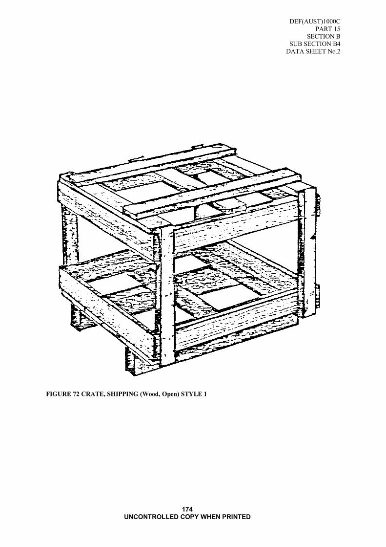
DEF(AUST)1000C
PART 15
SECTION B
SUB SECTION B4
DATA SHEET No.2
174 UNCONTROLLED COPY WHEN PRINTED
FIGURE 72 CRATE, SHIPPING (Wood, Open) STYLE 1

DEF(AUST)1000C
PART 15
SECTION B
SUB SECTION B4
DATA SHEET No. 3
175 UNCONTROLLED COPY WHEN PRINTED
DATA SHEET No. 3
CLASS 1: CRATE SHIPPING (WOOD, OPEN)
STYLE 2: UP TO 100 kg
1. SCOPE
1.1 This sheet covers the technical requirements of Class 1 Style 2 crates only and shall be read in conjunction with Sections 1 to 7 of this Specification.
2. DESCRIPTION
2.1 A battened lightweight crate of timber construction designed for mechanical lift. The style of crate
shall be as detailed in FIGURE 73.
3. INTENDED USE
3.1 A crate for large bulky packaging stores where the gross mass does not exceed 100 kg.
4. REQUIREMENTS
4.1 Materials
4.1.1 The materials used in construction and assembly of the crate shall be as detailed in TABLE 62.
4.2 Manufacture
4.2.1 Battens. Not less than two battens shall be attached across the top, bottom and both sides' components.
The side battens shall extend to cover the top batten and bottom bearers. The battens shall be located
approximately one sixth the length in from each end. Additional battens shall be provided where the
distance between outer battens exceeds 760 mm. Where bracing is indicated the angle between braces and adjacent vertical or horizontal members shall be between 30 and 60 degrees.
4.2.2 Bearers. There shall be not less than two bearers attached across the exterior of the bottom component
with fill in pieces where required. The bearer shall be located approximately one sixth the length in
from each end. Additional battens shall be provided where the distance between outer bearers exceeds
760 mm.
TABLE 62 MATERIALS LIST
MATERIAL REQUIREMENT mm
NOMINAL
FRAMEWORK AND BATTENS
Timber (Refer Paragraph 4.2.1) Size Refer Paragraph 4.5
Fastenings (Refer Paragraph 4.2.5)
Nails Length 40
Diameter 2.5 Staples Leg Length 40
BEARERS
Timber Width 75
Thickness 100
Fastenings
Nails Length 60
Diameter 3.15
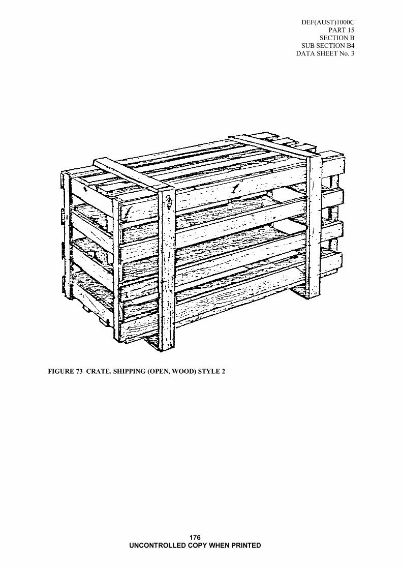
DEF(AUST)1000C
PART 15
SECTION B
SUB SECTION B4
DATA SHEET No. 3
176 UNCONTROLLED COPY WHEN PRINTED
FIGURE 73 CRATE. SHIPPING (OPEN, WOOD) STYLE 2
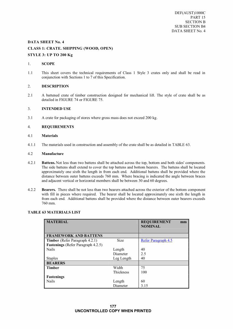
DEF(AUST)1000C
PART 15
SECTION B
SUB SECTION B4
DATA SHEET No. 4
177 UNCONTROLLED COPY WHEN PRINTED
DATA SHEET No. 4
CLASS 1: CRATE. SHIPPING (WOOD, OPEN)
STYLE 3: UP TO 200 Kg
1. SCOPE
1.1 This sheet covers the technical requirements of Class 1 Style 3 crates only and shall be read in conjunction with Sections 1 to 7 of this Specification.
2. DESCRIPTION
2.1 A battened crate of timber construction designed for mechanical lift. The style of crate shall be as
detailed in FIGURE 74 or FIGURE 75.
3. INTENDED USE
3.1 A crate for packaging of stores where gross mass does not exceed 200 kg.
4. REQUIREMENTS
4.1 Materials
4.1.1 The materials used in construction and assembly of the crate shall be as detailed in TABLE 63.
4.2 Manufacture
4.2.1 Battens. Not less than two battens shall be attached across the top, bottom and both sides' components.
The side battens shall extend to cover the top battens and bottom bearers. The battens shall be located
approximately one sixth the length in from each end. Additional battens shall be provided where the
distance between outer battens exceeds 760 mm. Where bracing is indicated the angle between braces and adjacent vertical or horizontal members shall be between 30 and 60 degrees.
4.2.2 Bearers. There shall be not less than two bearers attached across the exterior of the bottom component
with fill in pieces where required. The bearer shall be located approximately one sixth the length in
from each end. Additional battens shall be provided where the distance between outer bearers exceeds
760 mm.
TABLE 63 MATERIALS LIST
MATERIAL REQUIREMENT mm
NOMINAL
FRAMEWORK AND BATTENS
Timber (Refer Paragraph 4.2.1) Size Refer Paragraph 4.5
Fastenings (Refer Paragraph 4.2.5)
Nails Length 40
Diameter 2.5 Staples Leg Length 40
BEARERS
Timber Width 75
Thickness 100
Fastenings
Nails Length 60
Diameter 3.15

DEF(AUST)1000C
PART 15
SECTION B
SUB SECTION B4
DATA SHEET No. 4
178 UNCONTROLLED COPY WHEN PRINTED
FIGURE 74 CRATE, SHIPPING (OPEN, WOOD) STYLE 3 (3 Bearers)
FIGURE 75 CRATE, SHIPPING (OPEN, WOOD) STYLE 3 (2 Bearers)

DEF(AUST)1000C
PART 15
SECTION B
SUB SECTION B4
DATA SHEET No. 5
179 UNCONTROLLED COPY WHEN PRINTED
DATA SHEET No. 5
CLASS 1: CRATE, SHIPPING (OPEN, WOOD)
STYLE 4: UP TO 500 kg
1. SCOPE
1.1 This sheet covers the technical requirements of Class 1 Style 4 crates only and shall be read in
conjunction with Sections 1 to 7 of this Specification.
2. DESCRIPTION
2.1 A crate of timber construction designed for mechanical lift. The style of crate shall be as detailed in
FIGURE 76.
3. INTENDED USE
3.1 For domestic use and overseas shipment of stores not requiring the protection provided by boxes or
fully sheathed crates, and where the gross mass does not exceed 500 kg.
4. REQUIREMENTS
4.1 Material
4.1.1 The material used in construction and assembly of the crate shall be as detailed in TABLE 64.
4.2 Manufacture
4.2.l Battens. Not less than two battens shall be attached across the top and bottom of the crate. The top and
bottom batten shall extend to cover the sideboards, and the side battens shall be inside the sideboards.
The battens shall be located at the ends of each crate. Where bracing is indicated the angle between
braces and adjacent vertical or horizontal members shall be between 30 and 60 degrees. Additional battens shall be provided where the distance between battens exceeds 760 mm.
4.2.2 Bearers. There shall be not less than two bearers attached across the exterior of the bottom component
with fill in pieces where required, located approximately one sixth of the length in from each end of the
crate. Additional bearers shall be provided where the distance between outer bearers exceeds 760 mm.
Bearers shall be affixed by nailing or bolting through the bottom boards into the bearers.
TABLE 64 MATERIALS LIST
MATERIAL REQUIREMENT mm
NOMINAL
FRAMEWORK AND BATTENS
Timber (Refer Paragraph 4.2.1) Size Refer Paragraph 4.5
Fastenings (Refer Paragraph 4.2.5)
Nails Length 40
Diameter 2.5 Staples Leg Length 40
BEARERS
Timber Width 75
Thickness 100
Fastenings
Nails Length 60
Diameter 3.15

DEF(AUST)1000C
PART 15
SECTION B
SUB SECTION B4
DATA SHEET No. 5
180 UNCONTROLLED COPY WHEN PRINTED
FIGURE 76 CRATE, SHIPPING (OPEN WOOD) STYLE 4
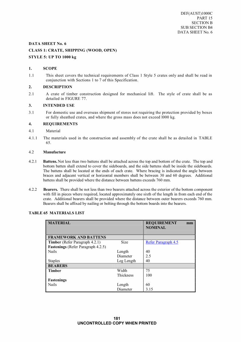
DEF(AUST)1000C
PART 15
SECTION B
SUB SECTION B4
DATA SHEET No. 6
181 UNCONTROLLED COPY WHEN PRINTED
DATA SHEET No. 6
CLASS 1: CRATE, SHIPPING (WOOD, OPEN)
STYLE 5: UP TO 1000 kg
1. SCOPE
1.1 This sheet covers the technical requirements of Class 1 Style 5 crates only and shall be read in
conjunction with Sections 1 to 7 of this Specification.
2. DESCRIPTION
2.1 A crate of timber construction designed for mechanical lift. The style of crate shall be as
detailed in FIGURE 77.
3. INTENDED USE
3.1 For domestic use and overseas shipment of stores not requiring the protection provided by boxes
or fully sheathed crates, and where the gross mass does not exceed l000 kg.
4. REQUIREMENTS
4.1 Material
4.1.1 The materials used in the construction and assembly of the crate shall be as detailed in TABLE
65.
4.2 Manufacture
4.2.1 Battens. Not less than two battens shall be attached across the top and bottom of the crate. The top and
bottom batten shall extend to cover the sideboards, and the side battens shall be inside the sideboards.
The battens shall be located at the ends of each crate. Where bracing is indicated the angle between braces and adjacent vertical or horizontal members shall be between 30 and 60 degrees. Additional
battens shall be provided where the distance between battens exceeds 760 mm.
4.2.2 Bearers. There shall be not less than two bearers attached across the exterior of the bottom component
with fill in pieces where required, located approximately one sixth of the length in from each end of the
crate. Additional bearers shall be provided where the distance between outer bearers exceeds 760 mm.
Bearers shall be affixed by nailing or bolting through the bottom boards into the bearers.
TABLE 65 MATERIALS LIST
MATERIAL REQUIREMENT mm
NOMINAL
FRAMEWORK AND BATTENS
Timber (Refer Paragraph 4.2.1) Size Refer Paragraph 4.5
Fastenings (Refer Paragraph 4.2.5)
Nails Length 40 Diameter 2.5
Staples Leg Length 40
BEARERS
Timber Width 75
Thickness 100
Fastenings
Nails Length 60
Diameter 3.15

DEF(AUST)1000C
PART 15
SECTION B
SUB SECTION B4
DATA SHEET No. 6
182 UNCONTROLLED COPY WHEN PRINTED
FIGURE 77 CRATE, SHIPPING (OPEN, WOOD) STYLE

DEF(AUST)1000C
PART 15
SECTION B
SUB SECTION B4
DATA SHEET No. 7
183 UNCONTROLLED COPY WHEN PRINTED
DATA SHEET No. 7
CLASS 2: CRATE, SHIPPING (WOOD, BOLTED AND SHEATHED)
STYLE 1: 1100 mm LENGTH AND 1100 DEPTH
1. SCOPE
1.1 This sheet covers the technical requirements of Class 2 Style 1 crates only and shall be read in conjunction with Sections 1 to 7 of this Specification.
2. DESCRIPTION
2.1 An assembled lidded crate of a framed construction designed for mechanical lift and bearer mounted.
The sheathing of top, sides and floor to be selected from one of the materials listed in Paragraph 4.2.4.
The style of crate shall be as detailed in FIGURE 78 to a maximum 1100 mm length and 1100 mm
depth.
3. INTENDED USE
3.1 For domestic and overseas shipment of stores which require protection from physical and climatic conditions.
4. REQUIREMENTS
4.1 Material
4.1.1 The material used in the construction and assembly of the crate shall he as detailed in TABLE 66.
4.2 Manufacture
4.2.1 Drain Channels. Prior to assembly of the top panel in Class 2 crates not less than two drain channels shall be cut across the underside of each member of the timber frame. They shall have nominal
dimensions of 10 mm width by 10 mm depth and shall be located not more than 280 mm from the ends
of each member. Where intermediate frame members have been inserted forming separate bays, each
bay shall have not less than two drain channels cut in each side member.
4.2.2 Assembly. Unless otherwise specified the following requirement shall be adhered to:
4.2.2.1 The sheathing shall be attached to the frame components in accordance with the nailing pattern in Data
Sheet No. 1. Where bracing is specified or indicated, the angle between braces and adjacent vertical or
horizontal member shall be between 30 and 60 degrees. The final assembly shall be by bolting.
4.2.3 Bearers. There shall be not less than two bearers attached cross the exterior of the bottom components. A fill in piece shall be fitted in between the bottom frame components and the bearers as floor support.
The bearers shall be fixed by nailing or bolting through the base. The bearers shall be located
approximately one sixth of the length in from each end. Additional bearers shall be provided where the
distance between bearers exceeds 760 mm.

DEF(AUST)1000C
PART 15
SECTION B
SUB SECTION B4
DATA SHEET No. 7
184 UNCONTROLLED COPY WHEN PRINTED
TABLE 66 MATERIALS LIST
MATERIAL REQUIREMENT
mm NOMINAL
SIDES TOP AND BOTTOM PANELS
Framework
Timber (Refer Paragraph 4.2.1) width 50
thickness 50
Fastenings (Refer Paragraph 4.2.5)
Nails length 150
diameter 5.6
Sheathing (Refer Paragraph 4.2.4)
Materials
Particle Board thickness 6.5 (min)
Hardboard 6.0 (min) Plywood 6.0
OSB 6.5 (min)
Fastenings
Nails length 60
diameter 2
Staples leg length 40
Base
Framing (Between floor and Bearer)
Timber width 75
thickness 50
BEARERS
Timber width 75 thickness 100
Fastenings
Nails length 75
diameter 3.75
Bolts length 80
diameter 10
ASSEMBLY
Fastenings
Bolts length 120
diameter 10
Nails length diameter
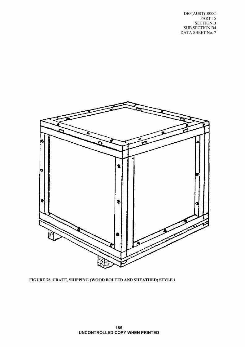
DEF(AUST)1000C
PART 15
SECTION B
SUB SECTION B4
DATA SHEET No. 7
185 UNCONTROLLED COPY WHEN PRINTED
FIGURE 78 CRATE, SHIPPING (WOOD BOLTED AND SHEATHED) STYLE 1

DEF(AUST)1000C
PART 15
SECTION B
SUB SECTION B4
DATA SHEET No. 7
186 UNCONTROLLED COPY WHEN PRINTED
Blank Page
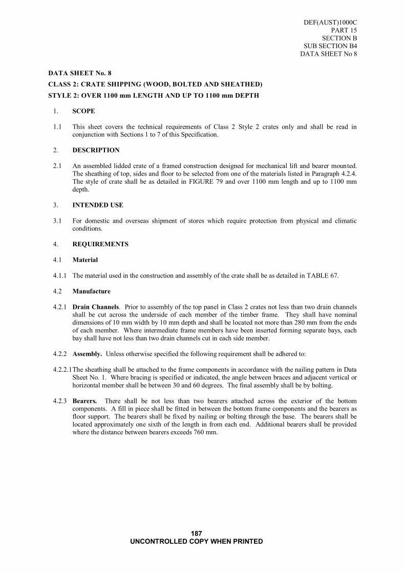
DEF(AUST)1000C
PART 15
SECTION B
SUB SECTION B4
DATA SHEET No 8
187 UNCONTROLLED COPY WHEN PRINTED
DATA SHEET No. 8
CLASS 2: CRATE SHIPPING (WOOD, BOLTED AND SHEATHED)
STYLE 2: OVER 1100 mm LENGTH AND UP TO 1100 mm DEPTH
1. SCOPE
1.1 This sheet covers the technical requirements of Class 2 Style 2 crates only and shall be read in conjunction with Sections 1 to 7 of this Specification.
2. DESCRIPTION
2.1 An assembled lidded crate of a framed construction designed for mechanical lift and bearer mounted.
The sheathing of top, sides and floor to be selected from one of the materials listed in Paragraph 4.2.4.
The style of crate shall be as detailed in FIGURE 79 and over 1100 mm length and up to 1100 mm
depth.
3. INTENDED USE
3.1 For domestic and overseas shipment of stores which require protection from physical and climatic conditions.
4. REQUIREMENTS
4.1 Material
4.1.1 The material used in the construction and assembly of the crate shall be as detailed in TABLE 67.
4.2 Manufacture
4.2.1 Drain Channels. Prior to assembly of the top panel in Class 2 crates not less than two drain channels shall be cut across the underside of each member of the timber frame. They shall have nominal
dimensions of 10 mm width by 10 mm depth and shall be located not more than 280 mm from the ends
of each member. Where intermediate frame members have been inserted forming separate bays, each
bay shall have not less than two drain channels cut in each side member.
4.2.2 Assembly. Unless otherwise specified the following requirement shall be adhered to:
4.2.2.1 The sheathing shall be attached to the frame components in accordance with the nailing pattern in Data
Sheet No. 1. Where bracing is specified or indicated, the angle between braces and adjacent vertical or
horizontal member shall be between 30 and 60 degrees. The final assembly shall be by bolting.
4.2.3 Bearers. There shall be not less than two bearers attached across the exterior of the bottom components. A fill in piece shall be fitted in between the bottom frame components and the bearers as
floor support. The bearers shall be fixed by nailing or bolting through the base. The bearers shall be
located approximately one sixth of the length in from each end. Additional bearers shall be provided
where the distance between bearers exceeds 760 mm.

DEF(AUST)1000C
PART 15
SECTION B
SUB SECTION B4
DATA SHEET No 8
188 UNCONTROLLED COPY WHEN PRINTED
TABLE 67 MATERIALS LIST
MATERIAL REQUIREMENT
mm NOMINAL
SIDES, TOP AND BOTTOM PANELS
Framework
Timber (Refer Paragraph 4.2.1) width 50
thickness 50
Fastenings (Refer Paragraph 4.2.5)
Nails length 150
diameter 5.6
Sheathing (Refer Paragraph 4.2.4)
Materials
Particle Board thickness 6.5 (min)
Hardboard 6.0 (min)
Plywood 6.0 OSB 6.5 (min)
Fastenings
Nails length 60
diameter 2
Staples leg length 40
Base
Framing (Between floor and Bearer)
Timber width 75
thickness 50
BEARERS
Timber width 75
thickness 100
Fastenings
Nails length 75
diameter 3.75
Bolts length 80
diameter 10
ASSEMBLY
Fastenings
Bolts length 120
diameter 10
Nails length
diameter

DEF(AUST)1000C
PART 15
SECTION B
SUB SECTION B4
DATA SHEET No 8
189 UNCONTROLLED COPY WHEN PRINTED
FIGURE 79 CRATE, SHIPPING (WOOD, BOLTED AND SHEATHED) STYLE 2

DEF(AUST)1000C
PART 15
SECTION B
SUB SECTION B4
DATA SHEET No 8
190 UNCONTROLLED COPY WHEN PRINTED
Blank Page

DEF(AUST)1000C
PART 15
SECTION B
SUB SECTION B4
DATA SHEET No. 9
191 UNCONTROLLED COPY WHEN PRINTED
DATA SHEET No. 9
CLASS 2: CRATE, SHIPPING (WOOD, BOLTED AND SHEATHED)
STYLE 3: OVER 1100 mm LENGTH AND 1100 mm DEPTH
1. SCOPE
l.1 This sheet covers the technical requirements of Class 2 Style 3 crates only and shall be read in
conjunction with Sections 1 to 7 of this Specification.
2. DESCRIPTION
2.1 An assembled lidded crate of a framed construction designed for mechanical lift and bearer mounted.
The sheathing of top, sides and floor to be selected from one of the materials listed in Paragraph 4.2.4.
The style of crate shall be as detailed in FIGURE 80 and over 1100 mm length and 1100 mm depth.
3. INTENDED USE
3.1 For domestic and overseas shipment of stores which require protection from physical and climatic
conditions.
4. REQUIREMENTS
4.1 Material
4.1.1. The material used in the construction and assembly of the crate shall be as detailed in TABLE 68.
4.2 Manufacture
4.2.1 Drain Channels. Prior to assembly of the top panel in Class 2 crates not less than two drain channels
shall be cut across the underside of each member of the timber frame. They shall have nominal
dimensions of 10 mm width by 10 mm depth and shall be located not more than 280 mm from the ends of each member. Where intermediate frame members have been inserted forming separate bays, each
bay shall have not less than two drain channels cut in each side member.
4.2.2 Assembly. Unless otherwise specified the following requirement shall be adhered to:
4.2.2.1 The sheathing shall be attached to the frame components in accordance with the nailing pattern in Data
Sheet No. 1. Where bracing is specified or indicated, the angle between braces and adjacent vertical or
horizontal member shall be between 30 and 60 degrees. The final assembly shall be by bolting.
4.2.3 Bearers. There shall be not less than two bearers attached across the exterior of the bottom
components. A fill in piece shall be fitted in between the bottom frame components and the bearers as
floor support. The bearers shall be fixed by nailing or bolting through the base. The bearers shall be located approximately one sixth of the length in from each end. Additional bearers shall be provided
where the distance between bearers exceeds 760 mm.
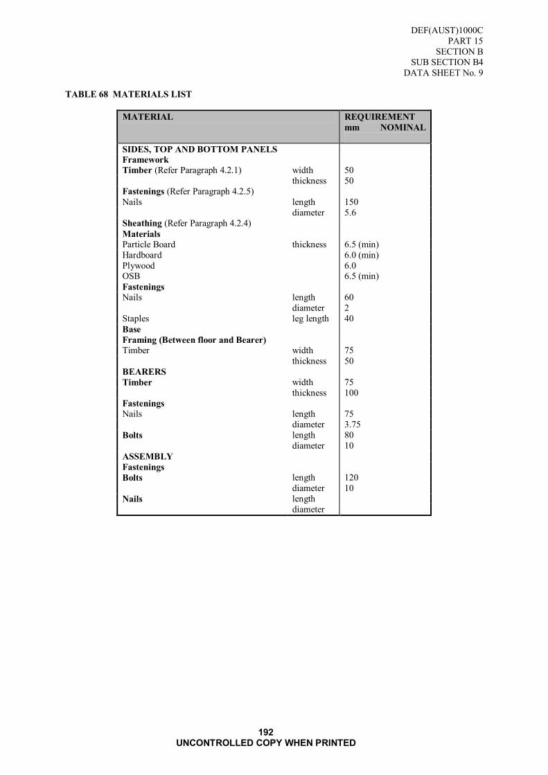
DEF(AUST)1000C
PART 15
SECTION B
SUB SECTION B4
DATA SHEET No. 9
192 UNCONTROLLED COPY WHEN PRINTED
TABLE 68 MATERIALS LIST
MATERIAL REQUIREMENT
mm NOMINAL
SIDES, TOP AND BOTTOM PANELS
Framework
Timber (Refer Paragraph 4.2.1) width 50
thickness 50
Fastenings (Refer Paragraph 4.2.5)
Nails length 150
diameter 5.6
Sheathing (Refer Paragraph 4.2.4)
Materials
Particle Board thickness 6.5 (min)
Hardboard 6.0 (min)
Plywood 6.0 OSB 6.5 (min)
Fastenings
Nails length 60
diameter 2
Staples leg length 40
Base
Framing (Between floor and Bearer)
Timber width 75
thickness 50
BEARERS
Timber width 75
thickness 100
Fastenings
Nails length 75
diameter 3.75
Bolts length 80
diameter 10
ASSEMBLY
Fastenings
Bolts length 120
diameter 10
Nails length
diameter

DEF(AUST)1000C
PART 15
SECTION B
SUB SECTION B4
DATA SHEET No. 9
193 UNCONTROLLED COPY WHEN PRINTED
FIGURE 80 CRATE SHIPPING (WOOD BOLTED AND SHEATHED) STYLE 3
DEF(AUST)1000C
PART 15
SECTION B
SUB SECTION B4
DATA SHEET No. 9
194 UNCONTROLLED COPY WHEN PRINTED
Blank Page

DEF(AUST)1000C
PART 15
SECTION C
195 UNCONTROLLED COPY WHEN PRINTED
SECTION C: METALS
Applicable data for Steel Cages is contained in DEF(AUST)1000, PART 20, Section 1 Chapter 2.

DEF(AUST)1000C
PART 15
SECTION E
196 UNCONTROLLED COPY WHEN PRINTED
SECTION D: POLYMERS
1. Applicable data for Box Liners is contained in DEF(AUST)1000, PART 3, Section G and Section L.
Applicable data for General Purpose Polymer Boxes is contained in DEF(AUST)1000, PART 20,
Section 1, Chapter 2.

DEF(AUST)1000C
PART 15
SECTION E
197 UNCONTROLLED COPY WHEN PRINTED
SECTION E: COMPOSITES
Applicable data for Box Liners is contained in DEF(AUST)1000, PART 3, Section H, Section I and Section L.

DEF(AUST)1000C
PART 15
SECTION F
198 UNCONTROLLED COPY WHEN PRINTED
SECTION F: OTHER

DEF(AUST)1000C
PART 15
199 UNCONTROLLED COPY WHEN PRINTED
PUBLICATION IMPROVEMENT REPORT AND REPLY (PIRR)
1.1. Introduction
Correction of publication deficiencies depends largely on feedback from the users. Publication Improvement Report and Reply (PIRR) forms (Form AO011) provide a straightforward and
readily available method for reporting deficiencies and suggesting improvements in the
publication to the Sponsor.
1.1.1. Typical deficiencies include:
errors on text, drawings, photographs, circuit diagrams, charts and tables;
omission of procedures;
ambiguous or inadequate data; conflict with other publications; and
errors in additional information.
1.1.2. Form completion and submission
The originator completes the PIRR form stating, in their own words, the deficiencies in the publication and where applicable, suggested amendments. Any comments that exceed the
space provided should be handwritten or typed on white paper and attached to the form. The
form is to be verified and signed by the originator's supervisor.
In all cases completed PIRR forms are to be sent directly to the publication Sponsor:
Assistant Program Coordinator
Army Standardisation Land Engineering Agency
3rd Floor, Defence Plaza Melbourne
661 Bourke Street MELBOURNE VIC 3000
mailto:[email protected]
facsimile: (03) 962 22942.
1.2. Sponsor Action
1.2.1. PIRR acknowledgement from a publication Sponsor does not constitute an approval
authority to amend a publication process or procedure.
1.2.2. Once the PIRR form has been received, the sponsor shall acknowledge receipt and advise the originator of any proposed action.
1.2.3. Form AO 011. PIRR forms are available on the DRN within Web Forms in electronic
format. Contractors without DRN access should obtain forms through the relevant Contract Authority.
NOTE 1: The PIRR web form (AO 11) is available on the DRN at the following
URL: http://intranet.defence.gov.au/webforms/

DEF(AUST)1000C
PART 15
200 UNCONTROLLED COPY WHEN PRINTED

DEF(AUST)1000C
PART 15
201 UNCONTROLLED COPY WHEN PRINTED
REQUESTS FOR DOCUMENTS
Requests for copies of this Specification/Standard, or certain copies of the listed Applicable Documents, may be obtained from Defence Technical Standards Document Centre listed
below:
DEPARTMENT OF DEFENCE (Maritime) Director Naval Platform Systems Department of Defence (Navy Office)
Campbell Park Offices (CP4-SP-013)
CANBERRA ACT 2600
Attention: NSTDC
Telephone: (06) 266 2906
Facsimile: (06) 266 2105
DEPARTMENT OF DEFENCE (Land) Land Engineering Agency
Attention: Technical Data Centre
Defence Plaza Melbourne
3rd Floor - 661 Bourke St
MELBOURNE CBD VIC 3000
Email: [email protected]
Telephone: (03) 9282 7404
Facsimile: (03) 9622 2942
DEPARTMENT OF DEFENCE (Air) Aerospace Technical Standards Document Centre (ATSDC)
Common Services System Support Office (CSSSO)
Building L7-1
RAAF Williams
Laverton VIC 3027 Telephone: (03) 9256 4236
Facsimile: (03) 9256 4888
DEFENCE RESTRICTED NETWORK (DRN)
Army Standardisation: http://vbmweb.sor.defence.gov.au/SPECS/Triservice/Directory.htm
Aerospace Technical Standards Document Centre http://wilap006.sor.defence.gov.au/Specs/defence.asp
ADF Maritime Material Requirements Set: http://defweb.cbr.defence.gov.au/navysyscom/mrs/HomePage.htm
(Note: The above websites addresses may change at any time without notice).
Other Users: Refer Land

Crown copyright reserved
PUBLISHED UNDER AUTHORITY OF
DEPARTMENT OF DEFENCE
COPIES OF DEF(AUST) DOCUMENTS ARE
OBTAINABLE FROM SOURCES SHOWN INSIDE BACK COVER


