DEF(AUST)1000C ADF PACKAGING; STANDARD …...This Standard is mandatory for use by the ADF and...
258
NSC PACK UNCONTROLLED COPY WHEN PRINTED COMMONWEALTH OF AUSTRALIA AUSTRALIAN DEFENCE STANDARD DEF(AUST)1000C ADF PACKAGING; STANDARD PART 3: PACKAGING PRACTICES AND MATERIALS * PUBLISHED UNDER AUTHORITY OF DEPARTMENT OF DEFENCE DEPARTMENT OF DEFENCE NOTICE THIS ON-LINE PUBLICATION IS A CONTROLLED COPY OF DEF(AUST)1000C, PART 03 CONFIRM ISSUE STATUS BEFORE USE – CONTACT LAND ENGINEERING AGENCY, EQUIPMENT INFORMATION OFFICE +61 3 9319 5355. WHEN PRINTED THIS PUBLICATION IS AN UNCONTROLLED COPY AND IS NOT SUBJECT TO UPDATE OR AMENDMENT ACTION.
Transcript of DEF(AUST)1000C ADF PACKAGING; STANDARD …...This Standard is mandatory for use by the ADF and...
NSC PACK UNCONTROLLED COPY WHEN PRINTED
COMMONWEALTH OF AUSTRALIA
AUSTRALIAN DEFENCE STANDARD
DEF(AUST)1000C
ADF PACKAGING;
STANDARD
PART 3: PACKAGING PRACTICES AND MATERIALS
*
PUBLISHED UNDER AUTHORITY OF DEPARTMENT OF DEFENCE
DEPARTMENT OF DEFENCE NOTICE
THIS ON-LINE PUBLICATION IS A CONTROLLED COPY OF DEF(AUST)1000C, PART 03
CONFIRM ISSUE STATUS BEFORE USE – CONTACT LAND ENGINEERING AGENCY,
EQUIPMENT INFORMATION OFFICE +61 3 9319 5355.
WHEN PRINTED THIS PUBLICATION IS AN UNCONTROLLED COPY AND IS NOT SUBJECT TO
UPDATE OR AMENDMENT ACTION.
UNCONTROLLED COPY WHEN PRINTED
DEF(AUST)1000C The following Government departments and industry organisations were consulted during the preparation of this document: Army, RAN and RAAF Defence National Storage and Distribution Centre Potential Suppliers from Industry Prepared by the ADF Packaging Committee of the Defence Standardisation Coordinating Group Published by: Sponsored by: Army Standardisation DGLEA, Land Engineering Agency and
the ADF Packaging Committee
UNCONTROLLED COPY WHEN PRINTED
AMENDMENT LIST
AMENDMENT
EFFECTED
NO
DATED
SIGNATURE
DATE
1 September 2004 2 December 2006
Page 1 new AQIS warning notice pages 204 to210 data on Stuffing a Container, and variouseditorial changes.
UNCONTROLLED COPY WHEN PRINTED
1
AUSTRALIAN DEFENCE STANDARD
DEF(AUST)1000C
ADF PACKAGING
PART 3 : PACKAGING PRACTICES AND MATERIALS
JULY 2000
Prepared by the ADF Packaging Committee under the Authority of the Defence Standardisation Coordination Group. Specific inquiries regarding the application of this Standard to Requests for Tender or contracts should be addressed to the Ordering Authority named in the Request for Tender, or to the Quality Assurance Authority named in the contract, as appropriate. This Standard is mandatory for use by the ADF and Contractors to the ADF. This Standard supersedes DEF(AUST)1000B PART 3: Design. SECTION C supersedes DEF(AUST)6119A: Liner Box/Case (Water Vapourproof or Waterproof). SECTION H supersedes DEF(AUST)5375A: Barrier Material Greaseproofed, Waterproofed Flexible and DEF(AUST)5358A: Barrier Material, Water Proofed Flexible Packaging Grades. SECTION I supersedes DEF(AUST)6003A: Primary Wrapping Materials. SECTION K in part supersedes DEF(AUST)6011A:Strapping, (Metallic and Non-Metallic). PART 3, SECTION E, implements the requirements of QSTAG 1149: Standard Methods of Preservation. DEF(AUST)1000C PART 3 SECTION L dated July 2000.
WARNINGS This Standard may call for use of substances and test procedures that may be injurious to health if adequate precautions are not taken. It refers only to technical suitability and in no way absolves either the supplier or user from statutory obligations relating to health and safety at any stage of manufacture or use. For timber products (ie packaging, dunnage) that are to be forwarded overseas there needs to be awareness of AQIS conditions on the export or import of timber products. Information on timber products is contained in DEF(AUST)1000, ADF Packaging, Part 10, AQIS Requirements. AQIS Requirements for the Australian Wood Packaging Certification Scheme (IPSM-15) are contained at the following AQIS URL: http://www.affa.gov.au/content/output.cfm?ObjectID=3E48F86-AA1A-11A1-B6300060B0AA00014&contType=outputs DEF(AUST)1000C is issued in 20 parts, with each part sub-divided into Sections. The 20 parts are: PART 1 : General Information PART 2 : Packaging Requirements PART 3 : Packaging Practices and Materials PART 4 : Standard Packaging Test Procedures PART 5 : Marking of Packages
DEF(AUST)1000C PART 3
UNCONTROLLED COPY WHEN PRINTED
2
PART 6 : Packing of Dangerous Goods (Except Dangerous Goods Class 1); Packaging Requirements and Packaging Mediums
PART 7 : Packaging for Materiel Susceptible to Damage by Electrostatic Discharge PART 8 : Defective Packaging Reporting System PART 9 : Requirements for Reusable Containers PART 10: Australian Quarantine Inspection Service (AQIS) Requirements PART 11: Unitisation PART 12: Bar Code Symbology PART 13: Packaging Material Catalogue PART 14: Minimum Packaging Specifications of Commercial Items PART 15: Packaging Specifications and Classification Systems PART 16: Creative Brief Template PART 17: Packaging ILS Checklist PART 18: Life Cycle Analysis PART 19: Caching PART 20: Techniques for Deployment, Packaging and Storage for Tropical Conditions Two or more parts may apply to any one packaging requirement and it is essential that all parts be considered and used where appropriate. This PART of the Defence standard concerns the military packaging design and specifies the general requirements to be observed in the packaging of Defence materiel. This standard does not apply to the packaging of Guided Weapons and Explosive Ordnance Branch (GWEO).
DEF(AUST)1000C PART 3
TABLE OF CONTENTS PARAGRAPH PAGE
UNCONTROLLED COPY WHEN PRINTED
3
SECTION A - INTRODUCTION 1. SCOPE ................................................................................................................................ 10 2. APPLICABLE DOCUMENTS........................................................................................... 10 SECTION B THE SELECTION OF PACKAGING TECHNIQUES 1. THE RISKS TO MATERIEL ............................................................................................. 13 2. PACKAGING TECHNIQUES AND MATERIALS .......................................................... 13 SECTION C TECHNICAL REQUIREMENTS FOR PROTECTION DURING STORAGE -
CLEANING 1. GENERAL .......................................................................................................................... 15 2. HANDLING AND SAFETY PRECAUTIONS.................................................................. 15 2.3 Toxicity ............................................................................................................................... 16 2.4 Health Hazards .................................................................................................................... 16 2.5 Flammability Classes .......................................................................................................... 16 TABLE C-I HANDLING AND SAFETY PRECAUTIONS.................................................................. 18 3. METHODS OF CLEANING .............................................................................................. 20 3.1 General Requirements ......................................................................................................... 20 3.2 Cleaning Factors.................................................................................................................. 20 3.2.1 Considerations..................................................................................................................... 20 3.2.2 Contaminant ........................................................................................................................ 20 3.2.3 Material ............................................................................................................................... 20 3.2.4 Construction ........................................................................................................................ 21 3.2.5 Surface ................................................................................................................................ 21 3.2.4 Disassembly of Items .......................................................................................................... 21 3.3 Types of Cleaning ............................................................................................................... 21 3.3.1 Precision Cleaning............................................................................................................... 21 3.3.2 Precision Cleaning Materials............................................................................................... 21 3.3.3 Gross Cleaning .................................................................................................................... 21 3.4 Cleaning Techniques ........................................................................................................... 21 3.4.1 Solution Cleaning................................................................................................................ 21 3.4.2 Spray Cleaning ................................................................................................................... 22 3.4.3 Ultrasonic (Sound) Cleaning ............................................................................................... 22 3.4.4 Vapour Cleaning ................................................................................................................. 22 3.4.5 Flush Cleaning .................................................................................................................... 22 3.4.6 Mechanical Cleaning........................................................................................................... 22 3.4.7 Gross Cleaning Processes.................................................................................................... 22 3.5 Cleaning Materials. ............................................................................................................. 22 3.6 Cleaning Inspection Tests ................................................................................................... 22 3.6.1 Visual Test for Cleanliness.................................................................................................. 22 3.6.2 Wipe Test for Cleanliness ................................................................................................... 23 3.6.3 Acidity/Alkalinity................................................................................................................ 23 3.7 Testing - Water Film ........................................................................................................... 23 3.7.1 Soil and Corrosion Products................................................................................................ 23 3.7.2 Rinsing ................................................................................................................................ 23 3.7.3 Methods of Cleaning ........................................................................................................... 24 TABLE C-II SELECTION CHART FOR CLEANING PROCESSES.................................................... 25 TABLE C-III CLEANING MATERIALS................................................................................................. 26 4. METHODS OF CLEANING PROCESSES ....................................................................... 28 TABLE C-IV ABRASIVE CLEANING SUB-METHODS ...................................................................... 37 TABLE C-V ACID CLEANING SUB METHODS................................................................................. 40 SECTION D TECHNICAL REQUIREMENTS FOR PROTECTION DURING STORAGE -
DRYING............................................................................................................................. 43 1. GENERAL .......................................................................................................................... 43 2. DRYING ............................................................................................................................. 43 2.1 General ................................................................................................................................ 43 2.1.1 Drying Factors..................................................................................................................... 43 2.1.2 Methods of Drying .............................................................................................................. 43
DEF(AUST)1000C PART 3
TABLE OF CONTENTS PARAGRAPH PAGE
UNCONTROLLED COPY WHEN PRINTED
4
TABLE DI DRYING PROCESSES ...................................................................................................... 44 SECTION E TECHNICAL REQUIREMENTS FOR PROTECTION DURING STORAGE
– PRESERVATION .......................................................................................................... 46 1. GENERAL .......................................................................................................................... 46 2. MATERIALS...................................................................................................................... 47 2.1 Preservation......................................................................................................................... 47 2.2 Preservatives ....................................................................................................................... 47 2.3 Methods of Preservation...................................................................................................... 47 2.3.1 Metallic Items...................................................................................................................... 48 2.3.2 Non-metallic Items.............................................................................................................. 48 2.3.3 Other.................................................................................................................................... 48 2.4 Volatile Corrosion Inhibitors (VCI). ................................................................................... 48 2.6 Barriers................................................................................................................................ 49 2.7 Desiccants ........................................................................................................................... 49 3. SELECTION AND METHOD OF PRESERVATION....................................................... 49 3.2 Selection of Preservation Method ....................................................................................... 50 3.3 Application of Preservation Methods.................................................................................. 50 TABLE EI TEMPORARY PROTECTIVES FOR METALLIC ITEMS .............................................. 51 TABLE EII TEMPORARY PROTECTIVES FOR NON-METALLIC ITEMS .................................... 54 4. AMERICAN BRITISH CANADIAN AUSTRALIAN (ABCA) PROCEDURAL
PRINCIPLES AND COMPARISON OF PRESERVATION METHODS......................... 54 4.2 PRESERVATION METHODS........................................................................................... 54 4.3 PRESERVATION - METHOD P1 ..................................................................................... 56 4.4 PRESERVATION - METHOD P2 ..................................................................................... 57 4.5 PRESERVATION - METHOD P3 ..................................................................................... 58 4.6 PRESERVATION - METHOD P4 ..................................................................................... 59 4.7 PRESERVATION - METHOD P5 ..................................................................................... 60 4.8 PRESERVATION - METHOD P6 ..................................................................................... 61 4.9 PRESERVATION - METHOD P7 ..................................................................................... 62 4.10 PRESERVATION - METHOD P9 ..................................................................................... 63 4.11 PRESERVATION - METHOD P10 ................................................................................... 64 4.12 PRESERVATION - METHOD P11 ................................................................................... 65 4.13 PRESERVATION - METHOD P12 ................................................................................... 66 4.14 PRESERVATION - METHOD P13 ................................................................................... 67 4.15 PRESERVATION - METHOD P14 ................................................................................... 68 4.17 PRESERVATION - METHOD P15 ................................................................................... 69 4.18 PRESERVATION - METHOD P16 ................................................................................... 70 4.19 PRESERVATION - METHOD P17 ................................................................................... 71 4.20 PRESERVATION - METHOD P30 ................................................................................... 72 4.21 PRESERVATION - METHOD P31 ................................................................................... 73 4.22 PRESERVATION - METHOD P32 ................................................................................... 74 4.23 PRESERVATION - METHOD P33 ................................................................................... 75 4.24 PRESERVATION - METHOD P34 ................................................................................... 76 4.25 PRESERVATION - METHOD P35 ................................................................................... 77 4.26 PRESERVATION - METHOD P36 ................................................................................... 78 4.27 PRESERVATION - METHOD P50 ................................................................................... 79 4.28 METHOD OF DETERMINATION OF STABILITY ........................................................ 80 4.29 METHOD OF DETERMINATION OF FLEXIBILITY .................................................... 81 4.30 METHOD OF DETERMINATION OF FREEDOM FROM CORROSIVE
PROPERTIES ..................................................................................................................... 82 4.31 METHOD OF EXPOSURE TO DRY HEAT..................................................................... 83 4.32 DETERMINATION OF MOISTURE-VAPOR PERMEABILITY.................................... 84 4.33 METHOD OF DETERMINATION OF FILM WEIGHT PER UNIT AREA .................... 85 Figure 1 Apparatus for Determining Flexibility ................................................................................ 86 Figure 2 (d) to (h) Packages for Stickiness Test ................................................................................ 87 Figure 3 Position of Packages for Dry Heat Test .............................................................................. 88 TABLE EIII TEMPORARY PROTECTIVES FOR NON-METALLIC STORES ................................. 89 TABLE EIV VOLATILE CORROSION INHIBITORS (VCI) .............................................................. 92
DEF(AUST)1000C PART 3
TABLE OF CONTENTS PARAGRAPH PAGE
UNCONTROLLED COPY WHEN PRINTED
5
ANNEX A CALCULATION OF QUANTITY OF DESICCANT REQUIRED .................................. 93 ANNEX B USE OF HUMIDITY INDICATORS................................................................................. 97 Figure 1 Humidity Indicator .............................................................................................................. 98 ANNEX C ABCA PROCEDURAL PRINCIPLES, STANDARD METHODS OF
PRESERVATION AND COMPARISON OF PRESERVATION METHODS ................. 99 SECTION F - BARRIER MATERIAL - BUNDLING - BALING - WRAPPING -
BLOCKING – BRACING .............................................................................................. 106 1. INTRODUCTION............................................................................................................. 106 2. HANDLING AND STORAGE......................................................................................... 106 3. SELECTING A BARRIER MATERIAL ......................................................................... 106 4. COMPOSITE BARRIER MATERIALS .......................................................................... 106 5. WATERPROOFED FLEXIBLE BARRIER MATERIAL............................................... 107 6. WATER VAPOURPROOFED FLEXIBLE BARRIER MATERIALS............................ 107 7. FLEXIBLE THERMOPLASTIC FILMS ......................................................................... 107 8. HEAT SEALABLE BARRIER MATERIALS................................................................. 107 9. STATIC CONDUCTIVITY IN PLASTIC FILMS........................................................... 107 10. BUNDLING...................................................................................................................... 108 11. METHODS OF BUNDLING............................................................................................ 108 Figure 1 BUNDLING...................................................................................................................... 108 Figure 2 BUNDLING...................................................................................................................... 108 Figure 3 BUNDLING...................................................................................................................... 109 12. BALING............................................................................................................................ 109 Figure 4 BALING............................................................................................................................ 109 13. WRAPPING...................................................................................................................... 110 14. PRIMARY WRAPPING................................................................................................... 110 Figure 5 PRIMARY WRAPPING................................................................................................... 111 15. CONTAINER WRAPPING.............................................................................................. 111 Figure 6 CONTAINER WRAPPING.............................................................................................. 112 16. TYPES OF PRIMARY WRAPPING MATERIALS........................................................ 112 Figure 7 SINGLE FACED CORRUGATED FIBRE BOARD ....................................................... 113 Figure 8 ALUMINIUM FOIL ......................................................................................................... 114 17. CONCLUSION. ................................................................................................................ 115 18. BLOCKING AND BRACING.......................................................................................... 115 18.13 Use of bulk materials......................................................................................................... 117 18.14 Use of spring devices ........................................................................................................ 118 Figure 9 TIMBER FITMENTS ....................................................................................................... 118 Figure 10 TIMBER FITMENTS ....................................................................................................... 118 Figure 11 TIMBER FITMENTS ....................................................................................................... 119 Figure 12 BLOCKING AND BRACING A LARGE HEAVY ITEM .............................................. 119 Figure 13 ATTACHMENT AND LOCATION OF TIMBER FITMENTS...................................... 120 Figure 14 SEALING THE BARRIER AT ATTACHMENT BOLTS............................................... 121 Figure 15 SELF-LOCATING CUSHION ARRANGEMENT.......................................................... 122 Figure 16 TYPICAL ARRANGEMENT OF SEPARATE CUSHIONS .......................................... 122 Figure 17 A METHOD OF REDUCING CUSHION AREA ON ONE FACE................................. 123 Figure 18 USE OF CORNER BLOCKS ........................................................................................... 123 Figure 19 METHOD OF INCREASING THE EFFECTIVE CUSHION AREA ............................. 124 Figure 20 METHOD OF STABILISING NARROW CUSHIONS................................................... 124 Figure 21 A SIMPLE SUSPENSION SYSTEM FOR A LIGHT FRAGILE ITEM ......................... 125 Figure 22 A HEAVY FRAGILE ITEM MOUNTED ON SOLID RUBBER SHEAR
MOUNTINGS................................................................................................................... 125 Figure 23 A METHOD OF LOCATING A HEAVY FRAGILE...................................................... 126 ANNEX A WRAPPING MATERIALS .............................................................................................. 127 ANNEX B PERFORMANCE DATA OF CUSHIONING MATERIALS, AND RELATIVE
PROPERTIES OF CUSHIONING MATERIALS AND SPACE FILLING MATERIALS AND DEVICES......................................................................................... 128
TABLE I PERFORMANCE DATA FOR CUSHIONING MATERIALS ....................................... 128 TABLE II RELATIVE PROPERTIES OF CUSHIONING AND SPACE-FILLING
MATERIALS AND DEVICES......................................................................................... 129
DEF(AUST)1000C PART 3
TABLE OF CONTENTS PARAGRAPH PAGE
UNCONTROLLED COPY WHEN PRINTED
6
SECTION G - LINER BOX/CASE; WATER-VAPOUR PROOF OR WATERPROOF; SPECIFICATION ........................................................................................................... 130
1. SCOPE .............................................................................................................................. 130 1.2 Classification..................................................................................................................... 130 2. DEFINITIONS.................................................................................................................. 130 3. REQUIREMENTS............................................................................................................ 130 TABLE I CLASSIFICATION OF DEFECTS .................................................................................. 132 4. PREPARATION FOR DELIVERY.................................................................................. 132 ANNEX A BOX LINER SEAM TEST ............................................................................................... 133 DATA SHEET 1 TYPE LB 1, LINER, BOX/CASE .................................................................................... 134 DATA SHEET 2 TYPE LB 2, LINER, BOX/CASE .................................................................................... 137 DATA SHEET 3 TYPE LB 3, LINER, BOX/CASE .................................................................................... 140 DATA SHEET 4 TYPE LB 4, LINER, BOX/CASE .................................................................................... 143 SECTION H BARRIER MATERIAL ................................................................................................. 146 PART A BARRIER MATERIAL, GREASEPROOFED, WATERPROOFED,
FLEXIBLE; SPECIFICATION..................................................................................... 146 1. SCOPE .............................................................................................................................. 146 2. REQUIREMENTS............................................................................................................ 146 TABLE I PHYSICAL PROPERTIES .......................................................................................... 147 TABLE II CLASSIFICATION OF DEFECTS .................................................................................. 149 3. PREPARATION FOR DELIVERY.................................................................................. 150 ANNEX A ADHESION ...................................................................................................................... 151 ANNEX B ELEVATED TEMPERATURE AGEING........................................................................ 152 ANNEX C GREASE RESISTANCE TEST........................................................................................ 153 ANNEX D LOW TEMPERATURE FLEXIBILITY .......................................................................... 154 ANNEX E SPRINGBACK ................................................................................................................. 155 ANNEX F DETERMINATION OF CHLORIDE............................................................................... 156 ANNEX G DETERMINATION OF SULPHATES ............................................................................ 157 ANNEX H WATER RESISTANCE ................................................................................................... 158 SECTION H BARRIER MATERIAL ................................................................................................. 159 PART B BARRIER MATERIAL, WATER PROOFED, FLEXIBLE PACKAGING
GRADES; SPECIFICATION ........................................................................................ 159 1. SCOPE .............................................................................................................................. 159 2. REQUIREMENTS............................................................................................................ 159 TABLE 1 CLASSIFICATION OF DEFECTS .................................................................................. 160 3. PREPARATION FOR DELIVERY.................................................................................. 160 ANNEX A DATA SHEETS ............................................................................................................... 161 DATA SHEET 1 CLASS 1: BARRIER MATERIAL, NON-REINFORCED, BITUMEN
LAMINATED KRAFT..................................................................................................... 161 DATA SHEET 2 CLASS 2: BARRIER MATERIAL, REINFORCED, BITUMEN LAMINATED
KRAFT.............................................................................................................................. 163 DATA SHEET 3 CLASS 3: BARRIER MATERIAL, REINFORCED, BITUMEN LAMINATED
KRAFT, HEAT SEALABLE............................................................................................ 165 DATA SHEET CLASS 4: BARRIER MATERIAL, HEAVILY REINFORCED, BITUMEN
LAMINATED KRAFT..................................................................................................... 167 DATA SHEET CLASS 5: BARRIER MATERIAL, HEAVILY REINFORCED, NON-STAINING,
PLASTIC LAMINATED, EXTENSIBLE KRAFT.......................................................... 169 DATA SHEET 6 CLASS 6: BARRIER MATERIAL, REINFORCED, NON-STAINING, PLASTIC
LAMINATED KRAFT..................................................................................................... 171 DATA SHEET 7 CLASS 7: BARRIER MATERIAL, REINFORCED, NON-STAINING, PLASTIC
LAMINATED KRAFT, PLASTIC COATED, HEAT SEALABLE................................ 173 SECTION I PRIMARY WRAPPING MATERIALS SPECIFICATION ....................................... 175 1. SCOPE .............................................................................................................................. 175 1.2 Classification..................................................................................................................... 175
DEF(AUST)1000C PART 3
TABLE OF CONTENTS PARAGRAPH PAGE
UNCONTROLLED COPY WHEN PRINTED
7
2. REQUIREMENTS............................................................................................................ 175 2.1 General .............................................................................................................................. 175 2.2 Storage Stability ................................................................................................................ 175 2.3 Acceptable Quality Levels ................................................................................................ 175 TABLE I CLASSIFICATION OF DEFECTS .................................................................................. 176 3. PREPARATION FOR DELIVERY.................................................................................. 176 3.1 Packaging .......................................................................................................................... 176 3.2 Marking............................................................................................................................. 176 DATA SHEET 1 CLASS 1 GRADE 1: PAPER, WRAPPING, TISSUE, CHEMICALLY TREATED,
TARNISH RETARDENT................................................................................................. 177 DATA SHEET 2 CLASS 1 GRADE 2: PAPER, WRAPPING, TISSUE, ACID FREE............................... 179 DATA SHEET 3 CLASS 1 GRADE 3: PAPER, WRAPPING, WHITE FIBRE, CHEMICALLY
NEUTRAL ........................................................................................................................ 180 DATA SHEET 4 CLASS 1 GRADE 4: PAPER, WRAPPING, KRAFT, HEAVY DUTY,
UNTREATED................................................................................................................... 181 DATA SHEET 5 CLASS 1 GRADE 5: PAPER, WRAPPING, KRAFT, MEDIUM DUTY,
UNTREATED................................................................................................................... 183 DATA SHEET 6 CLASS 1 GRADE 6: PAPER, WRAPPING, KRAFT, LIGHT DUTY,
UNTREATED................................................................................................................... 185 DATA SHEET 7 CLASS 1 GRADE 7: PAPER, WRAPPING, WAXED.................................................... 187 DATA SHEET 8 CLASS 1 GRADE 8: PAPER, VOLATILE CORROSION INHIBITOR TREATED ..... 190 DATA SHEET 9 CLASS 1 GRADE 9: PAPER, WRAPPING, VEGETABLE PARCHMENT.................. 193 ANNEX A DETERMINATION OF CHLORIDE............................................................................... 196 ANNEX B DETERMINATION OF SULPHATES ............................................................................ 197 SECTION J TECHNICAL REQUIREMENTS FOR PROTECTION DURING
DISTRIBUTION - CONTAINERS................................................................................ 198 1. GENERAL ........................................................................................................................ 198 2. DEFINITION .................................................................................................................... 198 3. SELECTION..................................................................................................................... 198 3.1 Container Functions .......................................................................................................... 198 3.2 Item Characteristics........................................................................................................... 199 3.3 Type of Load ..................................................................................................................... 199 4. EXTERIOR CONTAINERS............................................................................................. 199 4.1 Rationalisation................................................................................................................... 199 4.2 Cost of Containers............................................................................................................. 199 4.3 Availability of Materials ................................................................................................... 199 4.4 Ease of Assembly and Closure .......................................................................................... 200 4.5 Ease of Handling and Storage ........................................................................................... 200 4.6 Degree of Item Protection ................................................................................................. 200 4.7 Container Protection.......................................................................................................... 200 4.8 Reusability......................................................................................................................... 200 5. TYPES OF CONTAINERS .............................................................................................. 200 5.1 Bags and Sacks.................................................................................................................. 200 5.2 Fibreboard Containers ....................................................................................................... 201 5.3 Paperboard Containers ...................................................................................................... 201 5.4 Wooden Boxes .................................................................................................................. 201 5.5 Steel Drums....................................................................................................................... 201 5.6 Plastic Containers.............................................................................................................. 202 5.7 Crates ................................................................................................................................ 202 5.8 Special to Contents Containers (STCC) ............................................................................ 202 5.9 Reusable Metal Containers................................................................................................ 202 6. CONTAINER HUMIDITY CONTROL........................................................................... 203 6.1 Breather Valves ................................................................................................................. 203 6.2 Types of Valves................................................................................................................. 203 6.3 Temperature and Pressure Considerations ........................................................................ 203

DEF(AUST)1000C PART 3
TABLE OF CONTENTS PARAGRAPH PAGE
UNCONTROLLED COPY WHEN PRINTED
8
7. STUFFING THE CONTAINER.......................................................................................204 Figure 1a. Bonded block method of stuffing cardboard cartons......................................................... 205 Figure 1b. Unsatisfactory method of stuffing cardboard cartons........................................................ 205 Figure 2a. Cube utilisation (Under-utilised)....................................................................................... 206 Figure 2b. Cube utilisation (Optimum Load) ..................................................................................... 206 7.5 Bagged, Sacked And Baled Cargo .................................................................................... 206 Figure 3. Cross-tier stuffing.............................................................................................................. 207 7.6 Drums................................................................................................................................ 207 Figure 4. Drums stuffed tightly to prevent shifting (Plan View) ...................................................... 207 Figure 5. Bulkhead constructed to support load ............................................................................... 208 Figures 6 a – d. Interior Container Stuffing Arrangements of wooden boxes and crates (rear view) ......... 208 Figure 7. Distribution of heavy loads in containers .......................................................................... 209 Figure 8. Dunnage separating mixed commodities........................................................................... 210 Figure 9. Stuffing perishable commodities....................................................................................... 210 Figure 10. Frozen food stowage ......................................................................................................... 211 ANNEX A CONTAINER TYPE AND STYLE.................................................................................. 212 ANNEX B TYPE OF LOAD............................................................................................................... 214 Figure 1 TYPES OF LOAD ............................................................................................................ 214 SECTION K TECHNICAL REQUIREMENTS FOR PROTECTION DURING
DISTRIBUTION - FASTENERS AND CLOSURES................................................... 215 1. GENERAL ........................................................................................................................ 215 1.2 Methods............................................................................................................................. 215 2. FASTENERS .................................................................................................................... 215 2.1 Selection............................................................................................................................ 215 2.2 Method .............................................................................................................................. 215 3. NAILING .......................................................................................................................... 216 4. CORRUGATED FASTENERS ........................................................................................ 217 5. BOLTS, SCREWS AND RIVETS (Selection of) ............................................................. 217 6. SCREWS........................................................................................................................... 217 7. BOLTS .............................................................................................................................. 217 8. STRAPPING, GENERAL ................................................................................................ 218 8.1 Strapping Uses .................................................................................................................. 218 8.2 Strapping Materials ........................................................................................................... 218 8.3 Metallic Strapping ............................................................................................................. 219 8.4 Non-metallic Strapping ..................................................................................................... 219 8.5 Hand Tools ........................................................................................................................ 220 8.6 Powered Strapping Machines............................................................................................ 220 8.7 Use of Strapping................................................................................................................ 220 9. STAPLING ....................................................................................................................... 221 9.1 Advantages of Stapling ..................................................................................................... 221 9.2 Stapling Machines ............................................................................................................. 221 9.3 Staple Support ................................................................................................................... 222 9.4 Staple Use.......................................................................................................................... 222 9.5 Staple Effectiveness. ......................................................................................................... 222 10. PRESSURE SENSITIVE ADHESIVE PACKAGING TAPES........................................ 222 10.2 Paper Tapes ....................................................................................................................... 222 10.3 Filmic Tapes...................................................................................................................... 222 10.4 Cloth Tapes (Cotton Cloth) ............................................................................................... 223 10.5 Laminated Tapes ............................................................................................................... 223 10.6 Considerations in Selecting a Tape. .................................................................................. 223 10.7 Tape Specifications. .......................................................................................................... 224 11. TWINE.............................................................................................................................. 224 ANNEX A STRAPPING: METALLIC AND NON-METALLIC ...................................................... 225 TABLE I TOLERANCE................................................................................................................... 226 TABLE II THICKNESS TOLERANCE ............................................................................................ 226
AL2
DEF(AUST)1000C PART 3
TABLE OF CONTENTS PARAGRAPH PAGE
UNCONTROLLED COPY WHEN PRINTED
9
TABLE III WIDTH TOLERANCE..................................................................................................... 226 TABLE IV CLASSIFICATION OF DEFENCTS ............................................................................... 227 APPENDIX 1 DUCTILITY OF METALLIC STRAPPING.................................................................... 228 DATA SHEET 1 TYPE 1 GRADE 1 - PAINTED STEEL STRAPPING FLAT HIGH GRADE................ 229 DATA SHEET 2 TYPE 1 GRADE II - PAINTED STEEL STRAPPING FLAT - STANDARD
GRADE............................................................................................................................. 231 DATA SHEET 3 TYPE 1 GRADE III - STEEL STRAPPING FLAT HEAVY DUTY .............................. 233 DATA SHEET 4 TYPE 2 CLASS 1 - NOT METALLIC STRAPPING POLYPROPYLENE.................... 235 DATA SHEET 5 TYPE 2 CLASS 2 - NON-METALLIC STRAPPING POLYESTER .............................. 237 SECTION L GUIDE OF COMMON BARRIERS, WRAPS, CUSHIONING MATERIALS
& TAPES.......................................................................................................................... 239 1. SCOPE .............................................................................................................................. 239 2. SUMMARY ...................................................................................................................... 239 TABLE I BARRIER MATERIAL, GREASEPROOF, WATERPROOF, FLEXIBLE,
HEATSEALABLE............................................................................................................ 240 TABLE II BARRIER MATERIAL, WATER-VAPOURPROOF, GREASEPROOF,
FLEXIBLE, HEATSEALABLE ....................................................................................... 240 TABLE III BARRIER MATERIAL - SPECIAL APPLICATION..................................................... 241 TABLE IV BARRIER MATERIAL, WATER PROOFED, FLEXIBLE, PACKAGING
GRADES........................................................................................................................... 242 TABLE V WRAPPING MATERIALS ............................................................................................. 243 TABLE VI CUSHIONING MATERIALS ......................................................................................... 244 TABLE VII GENERAL PURPOSE PACKAGING TAPES ................................................................ 245 SECTION M FOAM-IN-PLACE SYSTEM 1. INTRODUCTION............................................................................................................. 246 2. PURPOSE ......................................................................................................................... 246 3. SAFETY PRECAUTIONS ............................................................................................... 246 4. HEALTH PRECAUTIONS .............................................................................................. 246 5. PROTECTIVE CLOTHING ............................................................................................. 246 6. EMERGENCY EQUIPMENT.......................................................................................... 246 7. FIRST AID........................................................................................................................ 246 8. VENTILATION OF WORK AND STORAGE AREAS.................................................. 247 9. STORAGE OF CHEMICAL COMPONENTS................................................................. 247 10. SELECTION OF ITEMS FOR FOAM-IN-PLACE PACKING....................................... 247 11. OPERATING PROCEDURES ......................................................................................... 247 12. ITEM PREPARATION FOR FOAM-IN-PLACE PROCESSING................................... 247 FIGURE 1 Projections to be padded/cushioned as required................................................................ 248 FIGURE 2 Prepared item to be placed in a polyethylene bag ............................................................. 248 13. TECHNIQUE.................................................................................................................... 249 FIGURE 3 Item packed in suitable container ...................................................................................... 249 FIGURE 4 Put foam mix into the container ........................................................................................ 249 FIGURE 5 Polyethylene foam placed over the item ........................................................................... 250 FIGURE 6 Item fully encapsulated in bed of foam ............................................................................. 250 14. MARKING........................................................................................................................ 250 15. OPENING INSTRUCTIONS............................................................................................ 250 16. REUSE/DISPOSAL.......................................................................................................... 251 17. DISPOSAL........................................................................................................................ 251 TABLE 1 FOAM-IN-PLACE SYSTEM ITEMS .............................................................................. 251
DEF(AUST)1000C PART 3
SECTION B
UNCONTROLLED COPY WHEN PRINTED
10
PART 3 – SECTION A
PACKAGING PRACTICES AND MATERIALS DESIGN 1. SCOPE
This PART of the Defence standard specifies the ADF packaging practices to meet Military Packaging Levels.
2. APPLICABLE DOCUMENTS
Reference may be necessary to the latest issue of the following documents:
Australian Department of Defence
DEF(AUST)206 - Handbook of Liquid Fuels, Lubricants and Allied Products.
Royal Australian Navy
DMS 159 - Heavy Duty Aluminium Faced Mouldable Wrap
Standards Australia
AS 1110 - ISO Metric Precision Hexagon Bolts and Screws.
AS 1111 - ISO Metric Hexagon Commercial Bolts and Screws.
AS 1152 - Test Sieves
AS 1301 - Methods of Test for Pulp and Paper
400s - Internal Tearing Resistance of Paper
403s - Bursting Strength of Paper
P404s - Tensile Strength of Paper and Paperboard
405s - Grammage of Non-Creped Paper and Board
P414m- Conditioning of Paper for Testing
P415m- Standard Atmosphere for Paper Testing
417s - Sampling Paper and Board for Testing
P419s - Water Vapour Transmission Rate of Paper
422s - Determination of the pH Value of Aqueous Extracts of Paper - Hot Extraction Method
424s - Determination of Titanium Dioxide in Paper, Paperboard, Pigments and Fillers
457s - Determination of Moisture Content in Paper, Board and Pulps
S 1580 - Paints and Related Materials - Methods of Test.
AS 1599 - Pressure Sensitive Adhesive Packaging Tapes.
AS 1604 - Timber - Preservative - Treated - Sawn and Round.
AS 1605 - Methods for the Sampling and analysis of wood Preservatives and Preservative Treated Wood.
AS 1627.1 - Cleaning using Liquid Solvents and Alkaline Solutions.
S 1627.4 - Abrasive Blast Cleaning.
AS 1627.5 - Pickling, Descaling and Oxide Removal

DEF(AUST)1000C PART 3
SECTION B
UNCONTROLLED COPY WHEN PRINTED
11
AS 1627.10 - Cleaning and Preparation of Metal Surfaces using Acid Solutions (non-immersion).
AS 1764 - Vegetable Parchment for Wrapping dairy Products
AS 1940 - The Storage and Handling of Flammable and Combustible Liquids.
AS 2281 - Flexible Cellular Polyurethane for Seat Cushioning and Bedding
AS 2334 - Steel Nails - Metric Series
AS 2400.6 - Paper and Paperboard
AS 2400.9.2 - Steel Drums
AS 2400.4.1 - Testing of Textiles for Colour Fastness; General Principles and Procedures
AS 2453 - Electroplated Coatings of Chromium for Engineering Applications.
AS 2767 - Rigid Plastic Containers
AS 2905 - Steel Drums
AS 3530 - Solvents - Mineral Turpentine and White Spirit.
AS 3537 - General Purpose Corrugated Fibreboard Boxes - Manufacturing Practice.
AS 3902 - Quality Systems for Production and Installation
AS 2508.6.011 - Tetrachloroethylene (Perchloroethylene) (S I Card) (Formerly AS K105).
AS 2508.6.013 - Trichloroethylene (S I Card) (Formerly AS K106).
UK Ministry of Defence
CS 2282 Para-Nitrophenol Solution for Tropic Proofing of Leather.
CS 2486 Preservative, Strippable, Hot Dipping (Ethyl-Cellulose Base).
CS 3037 Solution, Rubber Protective.
CS 3118 Oil Lubricating and Protective OX - 18.
DEF 177 Pentachlorophenyl Laurate Solution.
DEF STAN 91-36 Lubricating Oil, White, Joint Service Designation: OM-17
TS 10286- Expanded polyethylene Sheet Grades A, B, C and D
British Standards Institution
BS 1449- Steel Plate, Sheet and Strip
BS 1521- Waterproof Building Papers
BS 5056- Copper Naphthenate Wood Preservatives
BS 7344 Specification for Reeled Low Density Polyethylene Film for General Purpose Application
BS EN 10015-1 Protection of Electrostatic Sensitive Devices
BS EN ISO 11124-2 Chilled Iron Shot and Grit.
US Department of Defense
MIL-PRF-121 - Barrier Materials, Greaseproof, Waterproof, Flexible, Heat-Sealable
MIL-PRF-131 - Barrier Materials, Watervaporproof, Greaseproof, Flexible, Heat-Sealable
DEF(AUST)1000C PART 3
SECTION B
UNCONTROLLED COPY WHEN PRINTED
12
MIL-STD-1686 - Electrostatic Discharge Control Program for Protection of Electrical and Electronic Parts, Assemblies and Equipment (excluding electrically Initiated Explosive Devices)
MIL-L-2104 - Lubricating Oil, Internal Combustion Engine, Combat/Technical Service
MIL-C-6539 - Corrosion Preventive Compound, Petrolatum, Hot Application
MIL-I-8574 - Inhibitors, Corrosion, Volatile, Utilization of
MIL-C-11796 - Corrosion Preventive Compound, Petrolatum, Hot Application
MIL-C-15074 - Corrosion Preventive, Fingerprint Remover.
MIL-C-16173 - Corrosion Preventive Compound, Solvent Cutback, Cold-Application
MIL-T-81533 - - Trichloroethane 1,1,1, (Methylchloroform) Inhibited, Vapour Degreasing
US Federal Standards
O-I-501 - Inhibitor, Pickling (for use with Sulphuric Acid).
TT-W-572 - Wood Preservation, Water Repellent.
VV-L-800 - Lubricating Oil General Purpose Preservative, Water Displacing (Low Temperature).
American Society for Testing and Materials (ASTM)
Method E28-97 - Apparatus, Ring and Ball, Softening Point
Technical Association of Pulp and Paper Industry (USA)
TAPPI T457 - Stretch of Paper and Paperboard
TAPPI T475 - Bleeding Resistance of Asphalted Paper at Elevated Temperature
TAPPI T803 - Puncture and Stiffness of Paperboard, Corrugated and Solid Fibreboard
TAPPI 244 OM/88 - Acid in Soluble Ash in Pulp
TAPPI 438 OM/82 - Zinc and Cadmium in Paper
DEF(AUST)1000C PART 3
SECTION B
UNCONTROLLED COPY WHEN PRINTED
13
PART 3 SECTION B THE SELECTION OF PACKAGING TECHNIQUES
1. THE RISKS TO MATERIEL
1.1 Generally, the risks to materiel arise from two causes, namely:
a. vulnerability to climatic and/or similar features; and
b. susceptibility to physical damage in transport, handling and storage.
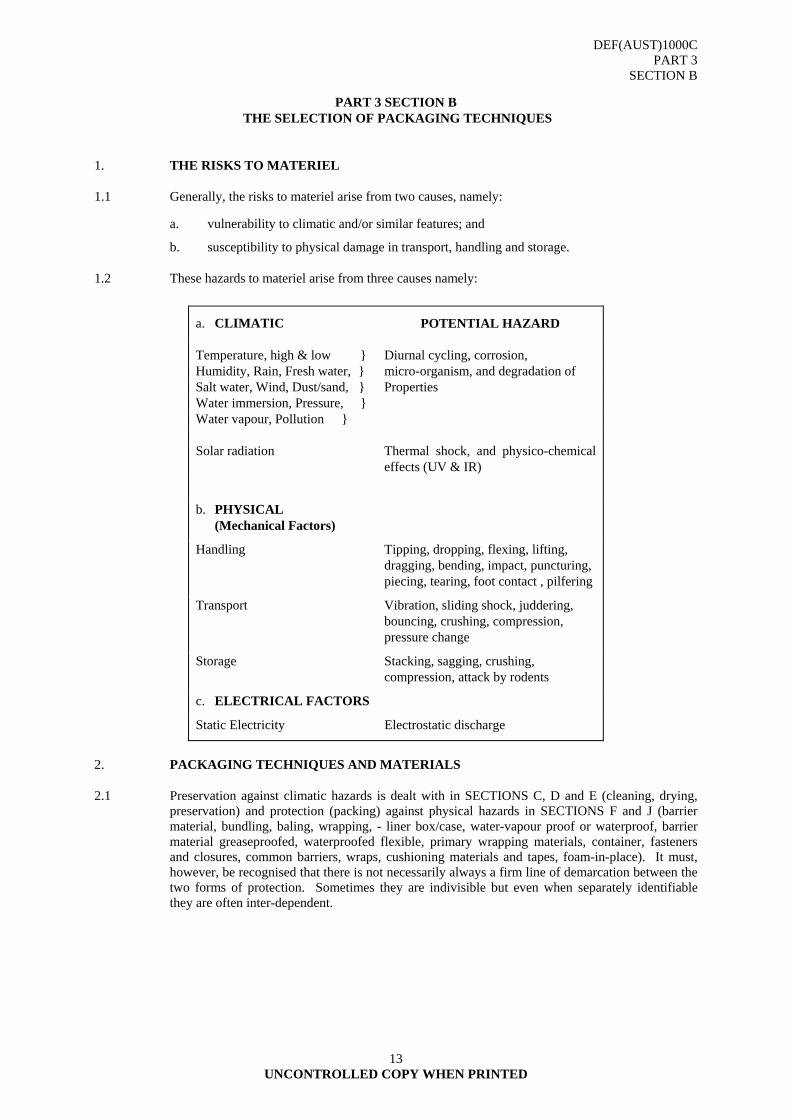
1.2 These hazards to materiel arise from three causes namely:
a. CLIMATIC POTENTIAL HAZARD
Temperature, high & low } Diurnal cycling, corrosion, Humidity, Rain, Fresh water, } micro-organism, and degradation of Salt water, Wind, Dust/sand, } Properties Water immersion, Pressure, } Water vapour, Pollution } Solar radiation Thermal shock, and physico-chemical
effects (UV & IR)
b. PHYSICAL (Mechanical Factors)
Handling Tipping, dropping, flexing, lifting, dragging, bending, impact, puncturing, piecing, tearing, foot contact , pilfering
Transport Vibration, sliding shock, juddering, bouncing, crushing, compression, pressure change
Storage Stacking, sagging, crushing, compression, attack by rodents
c. ELECTRICAL FACTORS
Static Electricity Electrostatic discharge
2. PACKAGING TECHNIQUES AND MATERIALS
2.1 Preservation against climatic hazards is dealt with in SECTIONS C, D and E (cleaning, drying, preservation) and protection (packing) against physical hazards in SECTIONS F and J (barrier material, bundling, baling, wrapping, - liner box/case, water-vapour proof or waterproof, barrier material greaseproofed, waterproofed flexible, primary wrapping materials, container, fasteners and closures, common barriers, wraps, cushioning materials and tapes, foam-in-place). It must, however, be recognised that there is not necessarily always a firm line of demarcation between the two forms of protection. Sometimes they are indivisible but even when separately identifiable they are often inter-dependent.
DEF(AUST)1000C PART 3
SECTION B
UNCONTROLLED COPY WHEN PRINTED
14
2.2 Each SECTION has been devised so that a logical progression may be made in the stages of building up a package. This has been done according to the differing types of materiel to be packed and those characteristics, which determine the choice of packaging technique. The text and tables are laid out to guide the designer in first making a general choice of technique and then proceeding to the more particular choice of detail (the approved techniques used in the selection and method of preservation of material, are shown in SECTION E, Paragraph 4).
2.3 In considering the susceptibility of the item to damage or deterioration under the prescribed conditions, a detailed knowledge of its constituent materials and construction is essential. In some instances it will be necessary to make tests on the item as a preliminary to gain quantitative and qualitative information on its vulnerability to damage and deterioration. Package testing to assess the suitability of a package design, in terms of its ability to meet the required level of protection for the item of materiel, is dealt with in DEF(AUST)1000, PART 4, and the tests set out therein may also be used as an aid to development of the package.
2.4 It is a good general rule to consider first the solution for the more difficult of the protection problems, i.e. storage or distribution for Level A ensuring that:
a. no redundant features are incorporated; and
b. that the climatic protection provided is not impaired, or put at risk during transportation by the methods employed for physical protection.
2.5 Compatibility of constituents of a package may be a problem and two of the less obvious aspects of this are the possibility of:
a. chemical attack by vapours from one material on other materials; and
b. the migration of ingredients of composite materials (e.g. plasticizers) from one material to another.
2.6 Most forms of packaging involve enclosing the item by wrapping or placing in a container or both. The consequent elimination of ventilation may well increase the possibility of deterioration.
2.6.1 Information in this Part affords a choice of packaging materials and/or techniques and the designer must make it clear on the specification if one of the alternatives must be used. When a particular substance or thickness of material is required this must be stated. Where the designer finds it necessary to specify a material and/or technique not covered within this standard they must, when preparing his specification, set out in detail the packaging material and/or process required.
2.7 Whilst this PART deals with the various processes in packaging and lists the materials employed in those processes, it does not differentiate between the various types of containers. It is necessary, therefore, for the designer to give adequate details of the container on the specification. This will frequently be done by reference to one of the published specifications dealing with containers. In some instances it will be necessary to specify the style of container and other particulars such as thickness of board and substance. Guidance is given within this Standard in SECTION J.
2.8 Packing of Electrostatic Sensitive Devices (ESSD). All related data is contained in DEF(AUST)1000, PART 7 (stand-alone document).

DEF(AUST)1000B PART 3
SECTION C
UNCONTROLLED COPY WHEN PRINTED
15
PART 3 SECTION C
TECHNICAL REQUIREMENTS FOR PROTECTION DURING STORAGE - CLEANING 1. GENERAL
1.1 This section covers methods of cleaning.
1.2 Only those methods listed in paragraph 3.7.3 of the Section shall be used.
CAUTION
A knowledge of the hazards involved with cleaning materials should be the foremost principle.
Personal injury can result from lack of attention to the proper use and cautions to be observed when using cleaning materials etc.
Cleaning materials can present certain hazards, e.g. trichloroethylene, although non-flammable, is narcotic and it is not desirable to breathe the vapour in any high concentration; petroleum solvents present fire hazards and all organic solvents, if in contact with the skin, have a degreasing effect which may make the skin liable to infection; alkalis, dry or in solution, have a similar effect on the skin and may also cause burns. Hot aqueous solutions and hot solvent baths may also cause burns.
If manufacturer's recommendations and precautions and the relevant statutory regulations are carefully observed no ill effects to personnel should occur.
When using cleaning materials in preservation plants, the necessary protective clothing and devices shall be available.
2. HANDLING AND SAFETY PRECAUTIONS
2.1 The Petroleum Oil and Lubricant (POL) products described in this standard vary greatly in their properties, toxicity and handling requirements.
2.2 Each of the data sheets contains an indication of the relative hazards associated with the product described through reference, by a group number, to the Handling and Safety Precautions set out in TABLE I. In this type of standard, such information can only be of a general nature. More detailed information on the hazards and endorsement procedures associated with each product may be obtained through:
a. SPT COMD - Environmental Officer
: 03 9282 7152
FAX: 03 9282 3799
b. DPAP - Defence Petroleum and Allied Products Joint Fuels and Lubricants Agency (JFLA), Level 3, Defence Plaza, 270 Pitt Street, Sydney 2000 : 02 9377 2111 FAX: 02 9377 3349
c. NAVY - Ship or Establishment Medical Officer;
d. ARMY - Area Medical Officer/Regimental Medical Officer; and
e RAAF - Base Environmental Health Officer.
AL2
DEF(AUST)1000B PART 3
SECTION C
UNCONTROLLED COPY WHEN PRINTED
16
2.3 Toxicity
2.3.1 The products described herein may contain additives of varying degrees of toxicity. Some products may also cause skin complaints or affect bodily functions by ingestion. Therefore when handling most POL products:
a. protect hands with either barrier cream or suitable gloves;
b. wear protective clothing;
c. use a face shield where appropriate; and
d. avoid inhaling or swallowing the product.
2.3.2 Before handling these POL products, it is advisable to ascertain correct first aid procedures in case an accident should occur.
2.4 Health Hazards
2.4.1 POL products can be hazardous to health by ingestion, inhalation, aspiration, skin and eye contact or absorption through the skin.
2.4.1.1 Ingestion. Swallowing a product can produce irritation of the mouth and gastro-intestinal tract.
2.4.1.2 Inhalation. Inhalation of a vapour mist into the lungs can cause irritation of the respiratory tract or further complications when absorbed into the blood stream.
2.4.1.3 Aspiration. Aspiration, that is introduction of liquids into the lungs, can be a direct result of vomiting following the ingestion of a product and can lead to pneumonitis.
2.4.1.4 Eye Contact. This can be caused by sprays, mists or splashing of a product and may lead to strong irritation of the eyes.
2.4.1.5 Skin Contact. Avoid prolonged and repeated skin contact with any petroleum product and use good hygiene practices as contact may result in both acute and chronic effects.
2.4.1.6 Acute Effect. Those effects which occur shortly after contact with the product.
2.4.1.7 Chronic Effect. Those effects which become obvious after a period of days, months, or years.
2.5 Flammability Classes
2.5.1 The products in this standard have been graded into storage and handling classification according to the definitions set out in AS 1940-1993. A flammable liquid as defined in the Australian Dangerous Goods Code, are as follows:
Class 3 -Flammable Liquids
(1) Flammable liquids are liquids, or mixtures of liquids, or liquids containing solids in solution or suspension (for example, paints, vanishes, lacquers, etc, but not including substances otherwise classified on account of their dangerous characteristics) that give off a flammable vapour at temperatures of not more than 60.5oC, closed-cup test, or not more than 65.6oC, open-cup test, normally referred to as flash point.
(2) Liquids meeting the above criteria with a flash point of more than 35oC that do not sustain combustion are not flammable liquids for the purpose of this code.
(3) Flammable liquids also include:
(a) liquids offered for transport at temperatures above their flash point; and
DEF(AUST)1000B PART 3
SECTION C
UNCONTROLLED COPY WHEN PRINTED
17
(b) substances that are transported or offered for transport at elevated temperatures in a liquid state and that give off a flammable vapour at a temperature at or below the maximum transport temperature
Combustible liquids
(1) Subject to sub-clause (2), for this purpose of the ADG Code (other than Chapter 3 and Appendix 2), combustible liquids are to be taken to be dangerous goods of Class 3 if:
(a) the combustible liquids are transported in a bulk container or a tank which is part of a vehicle; and
(b) the combustible liquids are transported on the same vehicle with;
(i) dangerous goods of Class 3 in bulk; or
(ii) packaged dangerous goods of Class 3 in an aggregate quantity of more than 1000L.
(2) Sub-clause (1) does not apply to the transport of combustible liquids and dangerous goods of Class 3 on a rail wagon if the combustible liquids and the dangerous goods are in a different bulk or freight containers, which are separated by at least 12 metres.
DEF(AUST)1000B PART 3
SECTION C
UNCONTROLLED COPY WHEN PRINTED
18
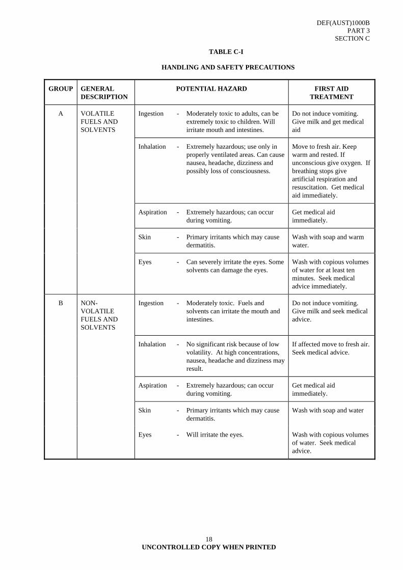
TABLE C-I
HANDLING AND SAFETY PRECAUTIONS
GROUP GENERAL DESCRIPTION
POTENTIAL HAZARD FIRST AID TREATMENT
A VOLATILE FUELS AND SOLVENTS
Ingestion - Moderately toxic to adults, can be extremely toxic to children. Will irritate mouth and intestines.
Do not induce vomiting. Give milk and get medical aid
Inhalation - Extremely hazardous; use only in properly ventilated areas. Can cause nausea, headache, dizziness and possibly loss of consciousness.
Move to fresh air. Keep warm and rested. If unconscious give oxygen. If breathing stops give artificial respiration and resuscitation. Get medical aid immediately.
Aspiration - Extremely hazardous; can occur during vomiting.
Get medical aid immediately.
Skin - Primary irritants which may cause dermatitis.
Wash with soap and warm water.
Eyes - Can severely irritate the eyes. Some solvents can damage the eyes.
Wash with copious volumes of water for at least ten minutes. Seek medical advice immediately.
B NON-VOLATILE FUELS AND SOLVENTS
Ingestion - Moderately toxic. Fuels and solvents can irritate the mouth and intestines.
Do not induce vomiting. Give milk and seek medical advice.
Inhalation - No significant risk because of low volatility. At high concentrations, nausea, headache and dizziness may result.
If affected move to fresh air. Seek medical advice.
Aspiration - Extremely hazardous; can occur during vomiting.
Get medical aid immediately.
Skin - Primary irritants which may cause dermatitis.
Wash with soap and water
Eyes - Will irritate the eyes. Wash with copious volumes of water. Seek medical advice.
DEF(AUST)1000B PART 3
SECTION C
UNCONTROLLED COPY WHEN PRINTED
19
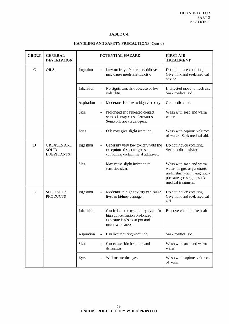
TABLE C-I
HANDLING AND SAFETY PRECAUTIONS (Cont’d)
GROUP GENERAL DESCRIPTION
POTENTIAL HAZARD FIRST AID TREATMENT
C OILS Ingestion - Low toxicity. Particular additives may cause moderate toxicity.
Do not induce vomiting. Give milk and seek medical advice
Inhalation - No significant risk because of low volatility.
If affected move to fresh air. Seek medical aid.
Aspiration - Moderate risk due to high viscosity. Get medical aid.
Skin - Prolonged and repeated contact with oils may cause dermatitis. Some oils are carcinogenic.
Wash with soap and warm water.
Eyes - Oils may give slight irritation. Wash with copious volumes of water. Seek medical aid.
D GREASES AND SOLID LUBRICANTS
Ingestion - Generally very low toxicity with the exception of special greases containing certain metal additives.
Do not induce vomiting. Seek medical advice.
Skin - May cause slight irritation to sensitive skins.
Wash with soap and warm water. If grease penetrates under skin when using high-pressure grease gun, seek medical treatment.
E SPECIALTY PRODUCTS
Ingestion - Moderate to high toxicity can cause liver or kidney damage.
Do not induce vomiting. Give milk and seek medical aid.
Inhalation - Can irritate the respiratory tract. At high concentration prolonged exposure leads to stupor and unconsciousness.
Remove victim to fresh air.
Aspiration - Can occur during vomiting. Seek medical aid.
Skin - Can cause skin irritation and dermatitis.
Wash with soap and warm water.
Eyes - Will irritate the eyes. Wash with copious volumes of water.

DEF(AUST)1000B PART 3
SECTION C
UNCONTROLLED COPY WHEN PRINTED
20
3. METHODS OF CLEANING
3.1 General Requirements
3.1.1 The success of preservation and packaging operations depends upon the cleaning of an item by approved processes. Prior to the application of any protective coating the surface shall be cleaned free of corrosion and foreign matter such as grease, wax, oils, soil, dust, swarf, workshop residues, fingerprints, perspiration marks, acid or alkali residues.
3.1.2 The processes of cleaning, drying, the applications of protective coatings and wrapping once commenced, should be carried out as a continuous and uninterrupted operation. When the process is unavoidably interrupted, temporary protection shall be applied to avoid further contamination. The items shall be inspected carefully before the process is recommenced. If contamination is apparent, the processes up to the stage reached shall be repeated.
3.1.3 Handling items with bare hands is liable to leave deposits upon metallic surfaces, which will cause corrosion; the deposits are not readily observed and their satisfactory removal involves special treatments. To avoid this, gloves shall be worn to prevent skin contact with the surfaces. Gloves shall be maintained in a clean state throughout all processes.
3.2 Cleaning Factors
3.2.1 Considerations. The choice of method and of the cleaning materials to be used depends upon the following considerations:
a. the nature of the contaminants to be removed; b. the material from which the item is constructed; c. the complexity of construction; d. the kind of surface finish; and e. the available material, plant and equipment.
3.2.2 Contaminant. Commonly, the surfaces are contaminated with oil or grease in conjunction with workshop residues and other dirt. Grease solvents, such as trichloroethylene or white spirit, can remove the grease and, by so doing, loosen and thus dislodge residues which are merely held by the grease. They do not, however, remove matter, which is actually adhering to the surface as, for example, perspiration residues. The removal of adherent dirt is usually effected by an aqueous alkaline cleaner which dissolves or emulsifies it and thus enables it to be washed away. The cleaners themselves must be followed by thorough rinsing and drying.
3.2.3 Material. Obviously one must not use a cleaning material which will chemically attack the material of the item or is likely to leave residues upon it which will do so subsequently. Trichloroethylene, white spirit, naphtha and petroleum solvents properly used will not react with metals. A choice from among mild alkaline cleaners can often be made according to the metal employed so as to avoid reaction with it. Strong alkaline cleaners are commonly used for cleaning steel parts, but must be avoided for use with light alloy, tin, zinc and brass since they will attack these metals chemically.
Where items are porous or have capillary spaces in their construction, and hence offer considerable practical difficulty in the removal of cleaner residues, the use of alkaline solutions for cleaning should be avoided since traces of residues are liable to set up corrosion eventually. Under this heading it is wise to include extended lap joints, riveted areas, spot welded joints and similar forms of construction.

DEF(AUST)1000B PART 3
SECTION C
UNCONTROLLED COPY WHEN PRINTED
21
For cleaning of items which are painted or varnished in whole or in part, trichloroethylene and the alkalis are unsuitable.
3.2.4 Construction. The use of cleaners which are in aqueous solution is appropriate only for the cleaning of single part items or the very simple type of assembled item. Items of a more complex character are liable to trap some of the cleaning solution in spite of subsequent rinsing. In preparing such items, therefore, for coating with a temporary protective, either (and this is preferable where possible) the individual parts of the assembly should be protected before assembly, or where this is impracticable, cleaning should be effected by the use of trichloroethylene or some other solvent type cleaner.
For complex assemblies, e.g. generators, starters, meters, etc, in the construction of which dissimilar materials are used (whether they be dissimilar metals or a mixture of metals and non-metallic materials), the use of dipping methods for cleaning is unsuitable. The metallic parts of such assemblies should be cleaned before they are assembled.
3.2.5 Surface. Consideration must be given to the fineness of finish or polish on the surfaces. Minor deterioration, such as that caused by fingerprints, can be tolerated on a casting whereas it would be unacceptable on a roller bearing. Where highly finished surfaces are concerned, it is most important to avoid any deposit or staining, and degreasing must be of a high order of efficiency. This is largely a matter of the correct operation of the particular cleaning method used. Experience shows that deposits and stains are more apt to result from minor departures from the correct method when alkaline cleaners are used than when solvent cleaners are used.
3.2.6 Disassembly of Items. Unless otherwise specified disassembly of complex assemblies shall be limited to the degree necessary to ensure the critical functioning surfaces are clean and free of contamination. Where practicable, internal parts of complex assemblies shall be cleaned prior to assembly and precautions taken to avoid latent contamination. All processes shall be thorough and shall cause no damage to the item or deterioration of its surfaces.
3.3 Types of Cleaning
3.3.1 Precision Cleaning. Precision cleaning is performed to achieve a level of particle cleanliness to a degree greater than that normally detected by visual means. Articles shall be visibly clean prior to the commencement of precision cleaning. Precision cleaning shall be performed in a controlled environment that permits the achievement and maintenance of the specified level of cleanliness for the item. Precision cleaning shall be capable of removing particles, films, biological forms, fibres and other forms of contaminants that are not visibly detected and could degrade the specific product or process. The levels of precision cleanliness shall be demonstrated, verified and evidence of inspection and acceptance provided. Precision cleaned items shall be suitably protected or packaged immediately following verification of cleanliness and prior to leaving the controlled environment.
3.3.2 Precision Cleaning Materials. Precision cleaning solutions and materials shall not react or combine with, etch or otherwise cause immediate or latent degradation of the item. Precision cleaning fluids shall be filtered, controlled and verified at a specified cleanliness level relative to the item.
3.3.3 Gross Cleaning. Gross cleaning is performed to achieve visibly clean items by the removal of contaminants such as weld scale, heat treatment scale, corrosion oxide films, oils, grease, shop soil, fuel and carbon deposits. Gross cleaning shall be considered a normal process not requiring special environmental controls, packaging, handling or storage beyond accepted good practice that will not degrade the quality of the product.
3.4 Cleaning Techniques
3.4.1 Solution Cleaning. The item is washed in fluid until all visible signs of contamination have been removed. Agitation is desirable, and brushing and scrubbing will hasten the cleaning process.
Solutions -
Cold : Organic solvents, detergent cleaners.
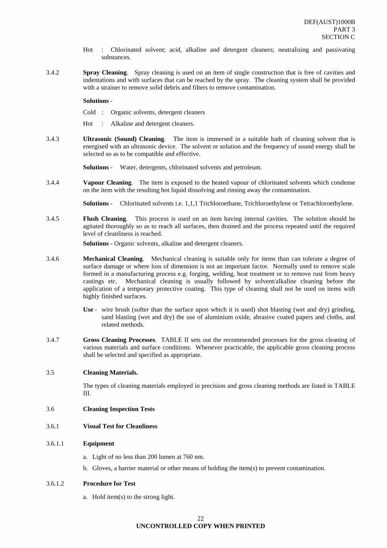
DEF(AUST)1000B PART 3
SECTION C
UNCONTROLLED COPY WHEN PRINTED
22
Hot : Chlorinated solvent; acid, alkaline and detergent cleaners; neutralising and passivating substances.
3.4.2 Spray Cleaning. Spray cleaning is used on an item of single construction that is free of cavities and indentations and with surfaces that can be reached by the spray. The cleaning system shall be provided with a strainer to remove solid debris and filters to remove contamination.
Solutions -
Cold : Organic solvents, detergent cleaners
Hot : Alkaline and detergent cleaners.
3.4.3 Ultrasonic (Sound) Cleaning. The item is immersed in a suitable bath of cleaning solvent that is energised with an ultrasonic device. The solvent or solution and the frequency of sound energy shall be selected so as to be compatible and effective.
Solutions - Water, detergents, chlorinated solvents and petroleum.
3.4.4 Vapour Cleaning. The item is exposed to the heated vapour of chlorinated solvents which condense on the item with the resulting hot liquid dissolving and rinsing away the contamination.
Solutions - Chlorinated solvents i.e. 1,1,1 Trichloroethane, Trichloroethylene or Tetrachloroethylene.
3.4.5 Flush Cleaning. This process is used on an item having internal cavities. The solution should be agitated thoroughly so as to reach all surfaces, then drained and the process repeated until the required level of cleanliness is reached. Solutions - Organic solvents, alkaline and detergent cleaners.
3.4.6 Mechanical Cleaning. Mechanical cleaning is suitable only for items than can tolerate a degree of surface damage or where loss of dimension is not an important factor. Normally used to remove scale formed in a manufacturing process e.g. forging, welding, heat treatment or to remove rust from heavy castings etc. Mechanical cleaning is usually followed by solvent/alkaline cleaning before the application of a temporary protective coating. This type of cleaning shall not be used on items with highly finished surfaces.
Use - wire brush (softer than the surface upon which it is used) shot blasting (wet and dry) grinding, sand blasting (wet and dry) the use of aluminium oxide, abrasive coated papers and cloths, and related methods.
3.4.7 Gross Cleaning Processes. TABLE II sets out the recommended processes for the gross cleaning of various materials and surface conditions. Whenever practicable, the applicable gross cleaning process shall be selected and specified as appropriate.
3.5 Cleaning Materials.
The types of cleaning materials employed in precision and gross cleaning methods are listed in TABLE III.
3.6 Cleaning Inspection Tests
3.6.1 Visual Test for Cleanliness
3.6.1.1 Equipment
a. Light of no less than 200 lumen at 760 nm.
b. Gloves, a barrier material or other means of holding the item(s) to prevent contamination.
3.6.1.2 Procedure for Test
a. Hold item(s) to the strong light.

DEF(AUST)1000B PART 3
SECTION C
UNCONTROLLED COPY WHEN PRINTED
23
b. Examine all surfaces for the presence of foreign materials and corrosion.
3.6.1.3 Results
a. Presence of dirt, oil, grease, corrosion or other foreign materials on the item shall be cause for rejection.
3.6.2 Wipe Test for Cleanliness
3.6.2.1 Equipment
a. Light of no less than 200 lumen at 760 nm.
b. One piece each of clean, combed cotton, lint free white and dark cloth.
3.6.2.2 Procedure
a. Wipe a portion of the item being tested with white cotton.
b. Wipe another portion of the item being tested with the dark cloth.
c. Examine both cloths for evidence of the presence of foreign material under the light.
3.6.2.3 Result
a. The presence of a dark smudge on the white cloth and/or a white deposit on the dark cloth shall be cause for rejection.
3.6.3 Acidity/Alkalinity
3.6.3.1 Equipment
a. Universal Indicator Papers.
b. Distilled water or demonised water.
c. Medicine dropper.
3.6.3.2 Procedure
a. If item(s) cannot be tested immediately after final rinse and while still wet, wet a small area of the dry item(s) with distilled or deionised water.
b. Touch a leaf of the Universal Indicator Paper to the wet surface.
c. Examine the wet paper for colour change.
d. Compare colour change with colour chart.
3.6.3.3 Result
a. A reading below pH 6.4 or above pH 8.3 shall be cause for rejection.
3.7 Testing - Water Film
3.7.1 Soil and Corrosion Products . Following cleaning and prior to the application of the phosphate process the surfaces of at least two items shall be rinsed in cold running tap water and the surfaces examined for discontinuity of the water film (water break). The surface shall be dried and examined visually for rust, corrosion products or soil. If the water film is discontinuous, all items in the batch shall be processed again.
3.7.2 Rinsing
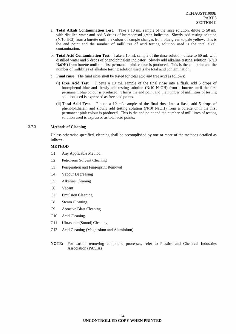
DEF(AUST)1000B PART 3
SECTION C
UNCONTROLLED COPY WHEN PRINTED
24
a. Total Alkali Contamination Test. Take a 10 mL sample of the rinse solution, dilute to 50 mL with distilled water and add 5 drops of bromocresol green indicator. Slowly add testing solution (N/10 HCl) from a burette until the colour of sample changes from blue green to pale yellow. This is the end point and the number of millilitres of acid testing solution used is the total alkali contamination.
b. Total Acid Contamination Test. Take a 10 mL sample of the rinse solution, dilute to 50 mL with distilled water and 5 drops of phenolphthalein indicator. Slowly add alkaline testing solution (N/10 NaOH) from burette until the first permanent pink colour is produced. This is the end point and the number of millilitres of alkaline testing solution used is the total acid contamination.
c. Final rinse. The final rinse shall be tested for total acid and free acid as follows:
(i) Free Acid Test. Pipette a 10 mL sample of the final rinse into a flask, add 5 drops of bromphenol blue and slowly add testing solution (N/10 NaOH) from a burette until the first permanent blue colour is produced. This is the end point and the number of millilitres of testing solution used is expressed as free acid points.
(ii) Total Acid Test. Pipette a 10 mL sample of the final rinse into a flask, add 5 drops of phenolphthalein and slowly add testing solution (N/10 NaOH) from a burette until the first permanent pink colour is produced. This is the end point and the number of millilitres of testing solution used is expressed as total acid points.
3.7.3 Methods of Cleaning
Unless otherwise specified, cleaning shall be accomplished by one or more of the methods detailed as follows:
METHOD
C1 Any Applicable Method
C2 Petroleum Solvent Cleaning
C3 Perspiration and Fingerprint Removal
C4 Vapour Degreasing
C5 Alkaline Cleaning
C6 Vacant
C7 Emulsion Cleaning
C8 Steam Cleaning
C9 Abrasive Blast Cleaning
C10 Acid Cleaning
C11 Ultrasonic (Sound) Cleaning
C12 Acid Cleaning (Magnesium and Aluminium)
NOTE: For carbon removing compound processes, refer to Plastics and Chemical Industries Association (PACIA)
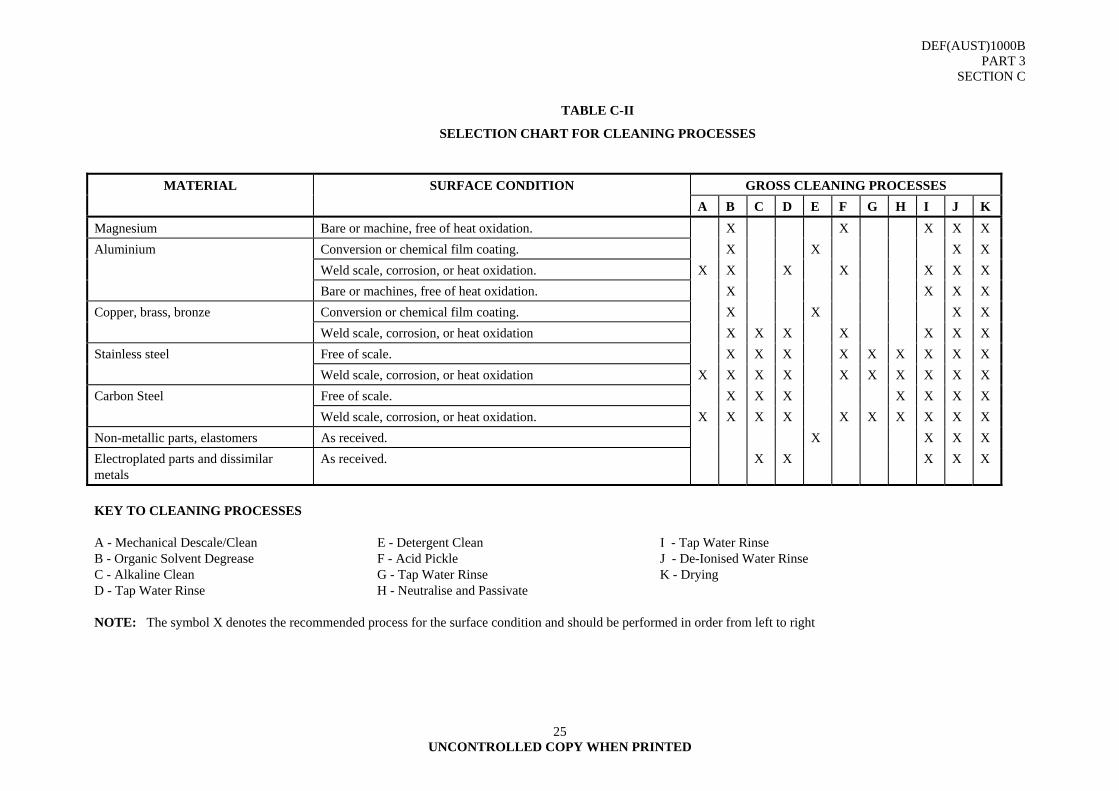
DEF(AUST)1000B PART 3
SECTION C
UNCONTROLLED COPY WHEN PRINTED
25
TABLE C-II
SELECTION CHART FOR CLEANING PROCESSES
MATERIAL SURFACE CONDITION GROSS CLEANING PROCESSES A B C D E F G H I J K Magnesium Bare or machine, free of heat oxidation. X X X X X Aluminium Conversion or chemical film coating. X X X X Weld scale, corrosion, or heat oxidation. X X X X X X X Bare or machines, free of heat oxidation. X X X X Copper, brass, bronze Conversion or chemical film coating. X X X X Weld scale, corrosion, or heat oxidation X X X X X X X Stainless steel Free of scale. X X X X X X X X X Weld scale, corrosion, or heat oxidation X X X X X X X X X X Carbon Steel Free of scale. X X X X X X X Weld scale, corrosion, or heat oxidation. X X X X X X X X X X Non-metallic parts, elastomers As received. X X X X Electroplated parts and dissimilar metals
As received. X X X X X
KEY TO CLEANING PROCESSES A - Mechanical Descale/Clean E - Detergent Clean I - Tap Water Rinse B - Organic Solvent Degrease F - Acid Pickle J - De-Ionised Water Rinse C - Alkaline Clean G - Tap Water Rinse K - Drying D - Tap Water Rinse H - Neutralise and Passivate NOTE: The symbol X denotes the recommended process for the surface condition and should be performed in order from left to right

DEF(AUST)1000B PART 3
SECTION C
UNCONTROLLED COPY WHEN PRINTED
26
TABLE C-III
CLEANING MATERIALS
CLEANER METHOD TYPE OF CLEANER REMOVAL OF: PRECAUTIONS
Solvent Organic
C2 Halogenated. e.g. white spirit, toluene, xylene, alcohol, ketones, fingerprint remover.
Oils grease hydrocarbon fuels.
C4 Chlorinated. e.g. trichloroethylene, tetrachloroethylene or trichloroethane.
Simple forms of oils, grease. Assemblies containing rubber, leather, fabrics, or any form of porous organic material and low temperature solders are not to be cleaned by vapour degreasing. EMEI WKSP E 432 for safety precautions.
Alkali C5.1 Heavy Duty Organic and inorganic contaminants e.g. shop dirt, soil, oily and water-soluble contaminants, wares and buffing compounds from steel.
Alkaline cleaners dissolve or etch certain metals such as aluminium or zinc.
C5.2 Mild Duty As above, primarily for non-ferrous metal items.
Vacant C6
Emulsion C7 Kerosene emulsified with pine oil, soaps and emulsifying agents.
Oil soluble and water-soluble contaminants e.g. pigmented, drawing, buffing, polishing compounds and flushing oils.
Assemblies containing rubber, leather, fabrics or any form of porous organic material are not to be cleaned by this process.

DEF(AUST)1000B PART 3
SECTION C
UNCONTROLLED COPY WHEN PRINTED
27
TABLE C-III (Cont’d)
CLEANING MATERIALS
CLEANER METHOD TYPE OF CLEANER REMOVAL OF: PRECAUTIONS
Steam Cleaning C8 Chemical cleaning action combined with the dissolving action of heat and the physical action of high pressure.
Soil, grease, and oil contaminants. Steam cleaning may damage electrical wiring insulation, upholstery materials, anti friction bearings.
Abrasive C9 Blast cleaning of steel surfaces. Mill scale, rust, welding scale, paint and dry contaminants.
Personal safety protection and precautions are essential.
Acid C10 Chemical immersion cleaning with inhibited: 1. Phosphoric acid 2. Sulphuric acid 3. Hydrochloric acid 4. Citric acid
Weld; mill scale, corrosion and oxide films. Oil and grease contaminants must be removed before immersion of the item in the acid solution.
Ultrasonic C11 High frequency sound energy cleaning e.g.: 1. De-ionised water 2. Solvent e.g. 1,1,2 Trichloroethylene
1,2,2 Trifluoroethane.
Primarily foreign particles and secondarily, other contaminants according to the type of cleaning solution used in the tank.
Care shall be taken that the sealing compound between the transducer disc and the solvent reservoir is not damaged by the type of cleaning solution used and that the solution and frequency is compatible with the item to be cleaned.
Acid (Magnesium and Aluminium)
C12 Chemical immersion cleaning with inhibited: 1. Chromic acid
Corrosion and oxide films. Oil and grease contaminants must be removed before immersion of the item in the acid solution.
DEF(AUST)1000C PART 3
SECTION C
UNCONTROLLED COPY WHEN PRINTED
28
4. METHODS OF CLEANING PROCESSES
C1. Any Applicable Method
C2. Solvent Cleaning
C3. Perspiration and Fingerprint Removal PX 116
C4. Vapour Degreasing
C5. Alkaline Cleaning
C6. Vacant
C7. Emulsion Cleaning
C8. Steam Cleaning
C9. Abrasive Blast Cleaning
C10. Acid Cleaning
C11. Ultrasound (Sound) Cleaning
C12. Acid Cleaning (Magnesium and Aluminium)
4.1 Cleaning - Method C1
4.1.1 Any Applicable Method
4.1.2 Material. (As appropriate).
4.1.3 Application
4.1.3.1 This method shall be used for an item for which no specific method or combination of methods can be specified or performed due to the limitation of plant, equipment, space, size and character of the item.
4.1.3.2 The item shall be cleaned by any process or combination of processes, which will accomplish thorough cleaning without damage. The process need not be confined to the cleaning methods listed herein.

DEF(AUST)1000C PART 3
SECTION C
UNCONTROLLED COPY WHEN PRINTED
29
4.2 Cleaning - Method C2
4.2.1 Solvent Cleaning
4.2.1.1 Specification. AS 3530-1988 - Solvent, Mineral Turpentine and White Spirit.
4.2.1.2 Composition. Hydrocarbons.
4.2.1.3 Characteristics Distillation: Initial boiling point, °C 145 - 155 Final boiling point, °C 200 (max) Flash point, Abel °C 31 (min)
4.2.1.4 Uses. General-purpose cleaning solvent including dry cleaning. Also used in lieu of Stoddard solvent test fluid in some fuel pump test benches.
4.2.1.5 Application. Solvent cleaning shall be used for the removal of oils and greases. Solvents will not remove rust or corrosion products, fingerprints and water-soluble contaminants. Refer to AS 1627.1 also.
4.2.1.6 Procedure
4.2.1.6.1 Immersion
a. Wear safety goggles, plastic gloves and apron.
b. Immerse item in solvent fluid.
c. Agitate thoroughly. Position to receive the most effective washing action.
d. Use a brush where necessary to remove dirt.
e. Remove from tank when visually clean.
f. Drain completely, allowing excess solvent to return to tank.
g. Immerse in a second tank of clean solvent.
h. Agitate thoroughly.
i. Remove and place on tray to drain.
4.2.1.6.2 Spray Cleaning
a. Wear safety goggles, plastic gloves and apron.
b. Load the item into spray tank.
c. Turn on spray pump; adjust nozzle and direct nozzle at the item.
d. Position item so that spray reaches all surfaces.
e. Remove from tank when visually clean and place in tray to drain.
4.2.1.6.3 Scrubbing and Wiping
a. Wear safety goggles, plastic gloves and apron.
b. Use clean lint free cleaning cloth, or brush.
c. Soak cleaning cloth or brush in clean solvent.
d. Apply soaked cloth or brush to areas that are dirty.
e. Use a combination of soaking, scrubbing and wiping as necessary.
DEF(AUST)1000C PART 3
SECTION C
UNCONTROLLED COPY WHEN PRINTED
30
f. Rinse off area with a clean cloth soaked in clean solvent.
g. Drain, shake or wipe off excess solvent.
4.2.1.7 NATO Stock Numbers
200 L Drum 6850-66-029-5299 Army, RAAF 20 L Drum 6850-66-086-8985 Army, RAAF 5 L Drum 6850-66-086-8986 Army
4.2.1.8 Handling and Safety Precautions
TABLE I, Group A Flammability Class 3.2
4.3 Cleaning - Method C3
4.3.1 Perspiration and Fingerprint Removal (Px-116)
4.3.1.1 Specification. MIL-C-15074D Corrosion Preventive, Fingerprint Remover.
4.3.1.2 Composition. Mineral oil with corrosion inhibitor and other additives.
4.3.1.3 Characteristics
Viscosity, at 38°C mm²/s 30 (max) Flash point, Tag °C 38 (min)
4.3.1.4 Uses. Removal of fingerprints from, and temporary preservation of metallic surfaces.
4.3.1.5 Application. The method shall be used for critical functioning or close tolerance surfaces, which may have traces of inorganic contamination such as salt residue from perspiration, fingerprints or traces of acids, which are not removed by petroleum or chlorinated solvents.
4.3.1.6 Procedure
a. Wear safety goggles, plastic gloves and apron.
b. Ensure the item has been cleaned in accordance with the applicable method.
c. Immerse in perspiration and fingerprint removal compound.
d. Agitate for 2 or 3 minutes.
e. If too large for complete immersion clean critical surfaces with a clean lint free cloth saturated with fingerprint remover.
f. After cleaning, rinse in a second tank containing clean petroleum solvent (Method C2)
g. Agitate in the petroleum solvent for at least 1 minute.
h. Remove and place on tray to drain.
4.3.1.7 NATO Stock Numbers 20 L Drum 8030-66-093-5645 Army 5 (US) Gal Drum 8030-00-252-8300 RAAF
4.3.1.8 Handling and Safety Precautions
TABLE I, Group C Flammability Class 3.2
DEF(AUST)1000C PART 3
SECTION C
UNCONTROLLED COPY WHEN PRINTED
31
4.3.1.9 Known Qualified Supplier/s
PX 116 Tectyl 275 - Valvoline,
Braycote 120 - Castrol or equivalent
4.4 Cleaning - Method C4A
4.4.1 Vapour Degreasing
4.4.1.1 Specification. AS 2508.6.011 - Tetrachloroethylene technical (perchloroethylene) (S I Card) (Formerly AS K105)
AS2508.6.013 - Trichloroethylene technical neutralized, stabilized Class 6.1(S I Card) (Formerly AS K106).
4.4.1.2 Application
4.4.1.2.1 This method shall be used for the removal of heavy contamination of oils and grease from non-porous items of simple construction, which are not damaged by temperatures in excess of 82°C. Chlorinated solvents do not remove fingerprints, rust or scale and other insoluble contaminants. Refer to AS 1627.1 also.
NOTE: Items joined with low melting solders may be damaged by the heat of the vapour.
4.4.1.3 Procedure
4.4.1.3.1 Vapour Immersion
a. Wear safety goggles, plastic gloves and apron.
b. Hold the item on hooks, racks or in baskets so that the condensed liquid can drain without collecting in pockets or crevices.
c. Lower slowly into the vapour.
d. When the vapour stops condensing on the item the cleaning has stopped.
e. Remove slowly from the vapour area. Hold briefly above the vapour level for cooling.
f. When cooled, return to vapour and repeat process until all contamination has been removed.
g. Remove slowly from the vapour area pausing to drain the liquid solvent into the degreaser.
h. Set aside to cool.
4.4.1.3.2 Vapour and Spray Cleaning. This supplementary process introduces the use of liquid spray obtained from an external source and directed into the surfaces of the item while held within the vapour area. It is suitable for the removal of solid particles such as chips, dust, swarf and dirt.
4.4.1.3.3 Liquid Immersion. This supplementary process is used where complex oils, greases, waxes and similar contaminants are required to be removed. Immersion in the boiling fluid loosens the contamination by the surging action and penetrates hard to reach crevices. After immersion the item is removed for cooling and finally entered into vapour to remove all traces of residue and contamination.
4.4.1.4 NATO Stock Numbers
Tetrachloroethylene technical (perchloroethylene)
6810-66-042-7730 RAAF
Trichloroethylene technical neutralized, stabilized Class 6.1
6810-66-069-0087 Army, Navy, RAAF
DEF(AUST)1000C PART 3
SECTION C
UNCONTROLLED COPY WHEN PRINTED
32
4.5 Cleaning - Method C4b
4.5.1 Vapour Degreasing
4.5.1.1 Specification. MIL-T-81533 - 1,1,1 - Trichloroethane (Methylchloroform) Inhibited, Vapour Degreasing
NOTE: AS 2871 Solvents - 1,1,1 - Trichloroethane (Inhibited) is unsuitable for Defence purposes.
4.5.1.2 Application
4.5.1.2.1 A solvent cleaner used for vapour degreasing and immersion cleaning of electrical or mechanical components. It may be used as a substitute for Trichlorotrifluoroethane (Freon TF) in baths which are not equipped with refrigeration coils. It is sometimes used to remove soiled residues of heavy detergents to give a final cleaning rinse.
4.5.1.3 Procedure
4.5.1.3.1 Vapour Immersion
a. Wear safety goggles, plastic gloves and apron.
b. Hold the item on hooks, racks or in baskets so that the condensed liquid can drain without collecting in pockets or crevices.
c. Lower slowly into the vapour.
d. When the vapour stops condensing on the item the cleaning has stopped.
e. Remove slowly from the vapour area. Hold briefly above the vapour level for cooling.
f. When cooled, return to vapour and repeat process until all contamination has been removed.
g. Remove slowly from the vapour area pausing to drain the liquid solvent into the degreaser.
h. Set aside to cool.
4.5.1.3.2 Vapour and Spray Cleaning. This supplementary process introduces the use of liquid spray obtained from an external source and directed into the surfaces of the item while held within the vapour area. It is suitable for the removal of solid particles such as chips, dust, swarf and dirt.
4.5.1.3.3 Liquid Immersion. This supplementary process is used where complex oils, greases, waxes and similar contaminants are required to be removed. Immersion in the boiling fluid loosens the contamination by the surging action and penetrates hard to reach crevices. After immersion the item is removed for cooling and finally entered into vapour to remove all traces of residue and contamination.
4.5.1.4 NATO Stock Numbers
6810-66-077-0630 Army, Navy, RAAF 200 L Drum
5 L Can 6810-66-026-7242 Army, Navy, RAAF
NOTE: Army (DME) has identified and catalogued a replacement for 1,1,1 Trichloroethane and products containing this chemical due to their environmentally hazardous nature. Loctite 7070 has been identified as a more environmentally solvent. The unit of issue is NSN 7930-01-423-0117, Cleaning Compound, Solvent-Detergent, Ozone Depleting Chemical Free Cleaner (is a 473mm non-aerosol can, shelf life of 12 months). Due care should be observed as the cleaner has a relatively low flash point and adequate ventilation should be used.
DEF(AUST)1000C PART 3
SECTION C
UNCONTROLLED COPY WHEN PRINTED
33
4.6 Cleaning - Method C5
4.6.1 Alkaline Cleaning
4.6.1.1 Specification. Commercial and AS 1627.1 - Cleaning using Liquid Solvents and Alkaline Solutions
4.6.1.2 Application. The alkaline cleaning method shall be used for items of simple construction having no critical surfaces composed of iron or steel. The method shall not be used for items having highly finished and precision surfaces, lap joints, riveted construction, porous materials or fine capillary tubes, and material of zinc, aluminium, magnesium, or their alloys or combinations. Refer to AS 1627.1 also.
4.6.1.3 Characteristics
pH value 11.8 - 12.5 Corrosion of metals aluminium mg 3 (max) steel mg 8 (max) copper mg 8 (max) brass mg 8 (max)
4.6.1.4 Procedure
4.6.1.4.1 Immersion
a. Wear safety goggles, plastic gloves and apron.
b. Heat the alkaline solution to 96°C to 100°C.
c. Lower the item into the heated solution and allow to soak from 2 to 10 minutes depending upon the degree of contamination.
d. Agitate and brush to speed up and improve cleaning.
e. Remove from the solution and drain surplus fluid.
f. Transfer to a hot water rinse tank heated to 80°C to 100°C.
g. Agitate to dissolve and rinse free of the alkaline residue.
h. Remove and inspect for cleanliness by watching for an even flow of water from surfaces without any breaking of the water film.
i. Drain.
4.6.1.4.2 Spray Cleaning
a. Wear safety goggles, plastic gloves and apron.
b. Load the item into spray tank.
c. Turn on spray pump, adjust nozzle and direct at the item.
d. Position so that spray reaches all surfaces.
e. Remove from tank when visually clean and place in tray to drain.
f. Transfer to a hot water rinse tank heated to 80°C to 100°C.
g. Agitate to dissolve and rinse free of the alkaline residues.
DEF(AUST)1000C PART 3
SECTION C
UNCONTROLLED COPY WHEN PRINTED
34
h. Remove from the tank and inspect for cleanliness by watching for an even flow of water from surfaces without any breaking of the water flow.
i. Drain.
4.6.1.5 NATO Stock Number
20 kg Drum 6850-66-013-7412 Army, Navy, RAAF
4.7 Cleaning - Method C6
VACANT
4.8 Cleaning - Method C7
4.8.1 Emulsion Cleaning
4.8.1.1 Specification. Commercial.
4.8.1.2 Application. Detergent emulsion cleaning shall be used to remove stubborn pigmented, drawing, buffing and polishing compounds, flushing oils and when the specified degree of cleaning is less than that obtained by petroleum solvent or alkaline cleaning.
4.8.1.2.1 Emulsion cleaning shall not be used for items containing fabrics, rubber and other organic materials unless it can be reliably determined that no harmful effects will result from its use.
4.8.1.3 Characteristics
°C 66 (min)
% 15 (max)
mg 3 (max)
mg 5 (max)
mg 8 (max)
mg 8 (max)
Flash point
Volatile matter
Corrosion of metals
aluminium
magnesium
steel
copper
zinc mg 7 (max)
4.8.1.4 Procedure
4.8.1.4.1 Immersion
a. Wear safety goggles, plastic gloves and apron.
b. Place the item in a basket, on hooks or on racks to provide for complete drainages from pockets and crevices.
c. Lower into emulsion tank and allow to soak for 1 to 10 minutes as determined by the amount of dirt to be removed.
d. Agitate and scrub to assist penetration and removal of contamination.
e. Remove for inspection of cleanliness and drainage of surplus emulsion.
DEF(AUST)1000C PART 3
SECTION C
UNCONTROLLED COPY WHEN PRINTED
35
f. Rinse for 30 to 60 seconds in overflowing hot rinse water maintained at a temperature above 80°C.
g. Remove from the tank and inspect for cleanliness by watching for an even flow of water from the surfaces without any breaking of the water film.
h. Drain.
4.8.1.4.2 Spray
a. Wear safety goggles, plastic gloves and apron.
b. Adjust spray nozzle for proper spraying.
c. Check filter screens in the circulating system to permit a free flow of cleaner through the unit.
d. Adjust temperature control to within the operational safety range of the equipment.
e. Load the item into the spray area.
f. Adjust nozzle spray pressure so that all surfaces will be reached with enough impact to remove the contaminant.
g. Inspect results of cleaning and when applicable adjust nozzles.
h. Remove for final inspection of cleanliness and drainage of surplus emulsion.
i. Rinse for 30 to 60 seconds in overflowing hot rinse water maintained at a temperature above 80°C.
j. Remove from the tank and inspect for cleanliness by watching for an even flow of water from the surface without any breaking of the water film.
k. Drain.
4.8.1.5 NATO Stock Number 20 L Drum 6850-66-091-1128 Army, Navy, RAAF 205 L Drum 6850-66-091-1127 Army, Navy, RAAF Bulk 6850-66-130-9442 Navy
4.8.1.6 Known Supplier/s
Surechem - Gamasol D5 or equivalent
4.9 Cleaning - Method C8
4.9.1 Steam Cleaning
4.9.1.1 Specification. Commercial.
4.9.1.2 Application. Steam cleaning shall be used for items, which are too large to be soaked in tanks or conveyed through spray zones. Steam cleaning shall not be used where electrical wiring is installed, for upholstery or in the location of anti friction and prepacked or preoiled bearings. Rinsing off all soap residues is of the utmost importance.
4.9.1.3 Characteristics pH value 12.0 (max) Corrosion of metals at 85° + 5°C steel mg 7 (max) copper mg 8 (max) brass mg 8 (max) aluminium mg 3 (max)
DEF(AUST)1000C PART 3
SECTION C
UNCONTROLLED COPY WHEN PRINTED
36
4.9.1.4 Procedure
The detailed operations of steam cleaning will vary with the type of equipment. The operator's manual shall be followed in all detail to ensure effective results.
a. Wear safety goggles and protective clothing.
b. Start cleaner in accordance with operator's manual.
c. Observe the appearance of the hot detergent solution emitting from the gun to ensure the soap concentrate is blending with the vapour.
d. Direct the vapour over the surface allowing the steam and soap compound to effectively carry out its cleansing action.
e. Observe the effect of the cleansing action. When all contaminants have been removed shut off the flow of soap concentrate and turn controls to rinse. A small amount of soap solution should flow through the system to prevent heating coil restriction.
f. Rinse off all residues with a high-pressure rinse wash.
4.9.1.5 Known Supplier/s
Chemtech, CT 18, Truck Wash (Part No CT18-201), 20L drum, or equivalent.
(Distributed by Unitech Group Pty Ltd 57 Balham Rd, Rocklea, QLD, 4106).
4.10 Cleaning - Method C9
4.10.1 Abrasive Blast Cleaning
4.10.1.1 Specification. AS 1627.4 - Abrasive blast cleaning. (Specifically abrasive cut steel shot and abrasive steel shot).
4.10.1.2 Application. Abrasive blast cleaning is a method of preparing steel surfaces to which protective coatings are subsequently applied. The method shall be used to remove mill scale, rust, welding scale, paint and other dry contaminants. Surfaces coated with heavy deposits of oil or grease shall be degreased by a solvent cleaning method, i.e., Method C2 or C4.
4.10.1.3 Methods. One of the sub-methods in TABLE IV shall be used.
4.10.1.4 Procedure
The procedure for abrasive blast cleaning will depend on the type of equipment employed. In general, the following steps are performed:
a. Wear the approved form of protective dress relative to the equipment operation.
b. Mask off any portion of work that must not be blasted.
c. Adjust pressures of compressed air to the type of surface being cleaned; 400 kPa to 600 kPa for hard materials and 200 kPa to 350 kPa for softer materials.
d. Direct the stream of abrasive at a 90º angle to the work surface and move it only as fast as the surface is cleaned.
e. If surfaces are dusty and have metal chips clinging to them after blasting, blow off with compressed air or rinse in an inhibited cleaning solution.
f. If iron dust and metallic particles continue to adhere to metal surfaces after rinsing, demagnetize items prior to blast cleaning.
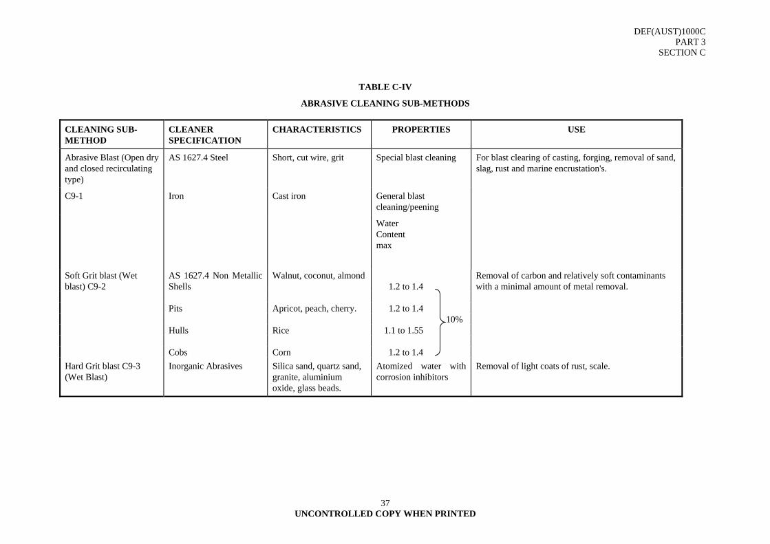
DEF(AUST)1000C PART 3
SECTION C
37 UNCONTROLLED COPY WHEN PRINTED
TABLE C-IV
ABRASIVE CLEANING SUB-METHODS
CLEANING SUB-METHOD
CLEANER SPECIFICATION
CHARACTERISTICS PROPERTIES USE
Abrasive Blast (Open dry and closed recirculating type)
AS 1627.4 Steel Short, cut wire, grit Special blast cleaning For blast clearing of casting, forging, removal of sand, slag, rust and marine encrustation's.
C9-1 Iron Cast iron General blast cleaning/peening
Water Content max
Soft Grit blast (Wet blast) C9-2
AS 1627.4 Non Metallic Shells
Walnut, coconut, almond 1.2 to 1.4
Removal of carbon and relatively soft contaminants with a minimal amount of metal removal.
Pits Apricot, peach, cherry. 1.2 to 1.4 10% Hulls Rice 1.1 to 1.55 Cobs Corn 1.2 to 1.4 Hard Grit blast C9-3 (Wet Blast)
Inorganic Abrasives Silica sand, quartz sand, granite, aluminium oxide, glass beads.
Atomized water with corrosion inhibitors
Removal of light coats of rust, scale.
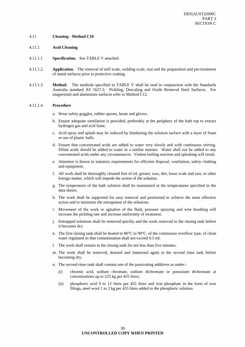
DEF(AUST)1000C PART 3
SECTION C
38 UNCONTROLLED COPY WHEN PRINTED
4.11 Cleaning - Method C10
4.11.1 Acid Cleaning
4.11.1.1 Specification. See TABLE V attached.
4.11.1.2 Application. The removal of mill scale, welding scale, rust and the preparation and pre-treatment of metal surfaces prior to protective coating.
4.11.1.3 Method. The methods specified in TABLE V shall be read in conjunction with the Standards Australia standard AS 1627.5: Pickling, Descaling and Oxide Removal Steel Surfaces. For magnesium and aluminium surfaces refer to Method C12.
4.11.1.4 Procedure
a. Wear safety goggles, rubber aprons, boots and gloves.
b. Ensure adequate ventilation is provided, preferably at the periphery of the bath top to extract hydrogen gas and acid fume.
c. Acid spray and splash may be reduced by blanketing the solution surface with a layer of foam or use of plastic balls.
d. Ensure that concentrated acids are added to water very slowly and with continuous stirring. Dilute acids should be added to water in a similar manner. Water shall not be added to any concentrated acids under any circumstances. Violent boiling reaction and splashing will result.
e. Attention is drawn to statutory requirements for efficient disposal, ventilation, safety clothing and equipment.
f. All work shall be thoroughly cleaned free of oil, grease, wax, dirt, loose scale and rust, or other foreign matter, which will impede the action of the solution.
g. The temperature of the bath solution shall be maintained at the temperatures specified in the data sheets.
h. The work shall be supported for easy removal and positioned to achieve the most effective action and to minimize the entrapment of the solutions.
i. Movement of the work or agitation of the fluid, pressure spraying and wire brushing will increase the pickling rate and increase uniformity of treatment.
j. Entrapped solutions shall be removed quickly and the work removed to the rinsing tank before it becomes dry.
k. The first rinsing tank shall be heated to 80°C to 90°C, of the continuous overflow type, of clean water regulated so that contamination shall not exceed 0.5 ml.
l. The work shall remain in the rinsing tank for not less than five minutes.
m. The work shall be removed, drained and immersed again in the second rinse tank before becoming dry.
n. The second rinse tank shall contain one of the passivating additives as under:-
(i) chromic acid, sodium chromate, sodium dichromate or potassium dichromate at concentrations up to 225 kg per 455 litres;
(ii) phosphoric acid 9 to 12 litres per 455 litres and iron phosphate in the form of iron filings, steel wool 1 to 2 kg per 455 litres added to the phosphoric solution.
DEF(AUST)1000C PART 3
SECTION C
UNCONTROLLED COPY WHEN PRINTED
39
o. The work shall remain in the second rinsing tank for not less than five minutes.
p. Remove, drain off all fluids and dry by Methods D1, D2 or D3.
q. When the construction of the work creates difficulties in the removal of water in the final rinse, the work shall be immersed in water displacing fluid as in Method D5.

DEF(AUST)1000C PART 3
SECTION C
40 UNCONTROLLED COPY WHEN PRINTED
CLEANING METHOD C10
TABLE C-V
ACID CLEANING SUB METHODS
CLEANING SUB-METHODS
CLEANING SPECIFICATION
CHARACTERISTICS PROPERTIES TEMPERATURE
Phosphoric Acid (C10-1)
AS 1627.5 & AS 1627.6
Immersion pickling 45 to 135 litres per 455 litres 0.3% inhibitor water
Heated to: 80°C to 95°C
Sulphuric Acid (C10-2)
Commercial Immersion pickling 23 to 45 litres per 455 litres 0.3% inhibitor water
60°C to 90°C
Hydrochloric Acid (C10-3)
AS 1627.5 & AS 1627.6
Immersion pickling 68 to 90 litres per 455 litres 0.3% inhibitor water
Ambient
Citric Acid (C10-4)
Commercial Immersion pickling 23 to 45 kg per 455 litres 0.3% inhibitor water
85°C to 98°C
DEF(AUST)1000C PART 3
SECTION C
UNCONTROLLED COPY WHEN PRINTED
41
4.12 Cleaning - Method C11
4.12.1 Ultrasonic (Sound) Cleaning
4.12.1.1 Specification. Commercial
4.12.1.2 Application. Ultrasonic cleaning shall be applied to non-absorbent materials such as glassware, metals, selected electronic equipment and moulded products. Contamination in cavities, indentations, small holes and other forms of inaccessible areas is removed to a degree not achieved by other processes. The process converts electrical energy into high frequency sound energy above the audible at 20,000 Hz. The action causes cold boiling of cavitation resulting in tiny bubbles forming and collapsing on the surface of the item producing a suction or scrubbing action.
4.12.1.3 Procedure
a. Wear safety goggles, plastic gloves and apron.
b. Place the item in a basket, on hooks or on racks to provide for complete drainage from pockets or crevices. (Best results are obtained when the number of parts being cleaned at the one time is kept to a minimum).
c. Slowly lower the item into the heated emulsion maintained at a predetermined temperature. Immersion time will depend on the type and amount of contamination to be removed.
d. Transfer the work slowly from the ultrasonic tank for final surface cleaning.
e. Additional final washing may be achieved by raising the work for spray rinse by a hand held director followed by a pure vapour rinse.
f. Withdraw the work slowly, ensuring all cavities and fluid retaining orifices are emptied during the withdrawal process. Remove from the rinsing water, and drain off all fluids from recesses and cavities.
g. Work will emerge warm, clean and dry.
4.12.1.4 NATO Stock Numbers
6850-66-091-1128 Army, Navy, RAAF 20 L Drum
205 L Drum 6850-66-091-1127 Army, Navy, RAAF
4.12.1.5 Known Supplier/s
Surechem - Gamasol D5 or equivalent
4.13 Cleaning - Method C12
4.13.1 Acid Cleaning (Magnesium and Aluminium)
4.13.1.1 Specification. AS 2453 Electroplated coatings of Chromium for Engineering Applications (Chromium Trioxide Technical (Chromic Acid)).
4.13.1.2 Application. Acid cleaning shall be used for the removal of corrosion appearing as whitish or whitish grey powder by one of the following procedures in accordance with AS 1627.10.
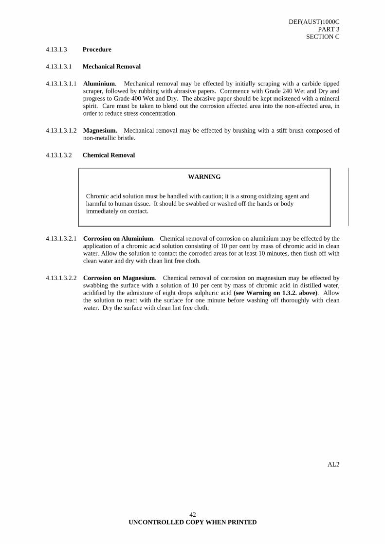
DEF(AUST)1000C PART 3
SECTION C
UNCONTROLLED COPY WHEN PRINTED
42
4.13.1.3 Procedure
4.13.1.3.1 Mechanical Removal
4.13.1.3.1.1 Aluminium. Mechanical removal may be effected by initially scraping with a carbide tipped scraper, followed by rubbing with abrasive papers. Commence with Grade 240 Wet and Dry and progress to Grade 400 Wet and Dry. The abrasive paper should be kept moistened with a mineral spirit. Care must be taken to blend out the corrosion affected area into the non-affected area, in order to reduce stress concentration.
4.13.1.3.1.2 Magnesium. Mechanical removal may be effected by brushing with a stiff brush composed of non-metallic bristle.
4.13.1.3.2 Chemical Removal
WARNING
Chromic acid solution must be handled with caution; it is a strong oxidizing agent and harmful to human tissue. It should be swabbed or washed off the hands or body immediately on contact.
4.13.1.3.2.1 Corrosion on Aluminium. Chemical removal of corrosion on aluminium may be effected by the application of a chromic acid solution consisting of 10 per cent by mass of chromic acid in clean water. Allow the solution to contact the corroded areas for at least 10 minutes, then flush off with clean water and dry with clean lint free cloth.
4.13.1.3.2.2 Corrosion on Magnesium. Chemical removal of corrosion on magnesium may be effected by swabbing the surface with a solution of 10 per cent by mass of chromic acid in distilled water, acidified by the admixture of eight drops sulphuric acid (see Warning on 1.3.2. above). Allow the solution to react with the surface for one minute before washing off thoroughly with clean water. Dry the surface with clean lint free cloth.
AL2

DEF(AUST)1000C PART 3
SECTION D
43 UNCONTROLLED COPY WHEN PRINTED
SECTION D - TECHNICAL REQUIREMENTS FOR PROTECTION DURING STORAGE - DRYING
1. GENERAL
This section covers methods of drying. Only those methods listed shall be used. 2. DRYING
2.1 General
The final stage of each cleaning process shall be thorough drying. Care shall be taken to ensure drying is complete, particularly in crevices, seams, joints and other areas that may retain pockets of moisture.
2.1.1 Drying Factors
2.1.1.1 Compressed Air. The prepared compressed air shall be dry and free from oil and dirt. The presence of moisture in air can be detected by blowing air at the outlet point onto a polished metal surface at room temperature and observing condensation. Moisture traps shall be located at the lowest point of the air delivery line and as close as is practicable to the take off point. Moisture traps shall be vented frequently during operation and filters cleaned regularly.
2.1.1.2 Heat Drying. Temperature of hot air ovens and infrared lamps shall be controlled to a level compatible with the temperature rating of the item to be dried, e.g. low melting point solders, steel tempered below 175º C or organic materials. Duralumin or other aluminium alloys age hardened at ordinary temperatures or at low temperature precipitation shall not be dried at temperatures exceeding 105°C.
2.1.2 Methods of Drying. Unless otherwise specified, drying shall be accomplished by one or more of the methods detailed as follows:
METHOD
D1 Compressed Air Drying
D2 Oven Drying
D3 Infrared Drying
D4 Drying by Wiping
D5 Drying with Water Displacing Fluid
(For more detail refer TABLE I)
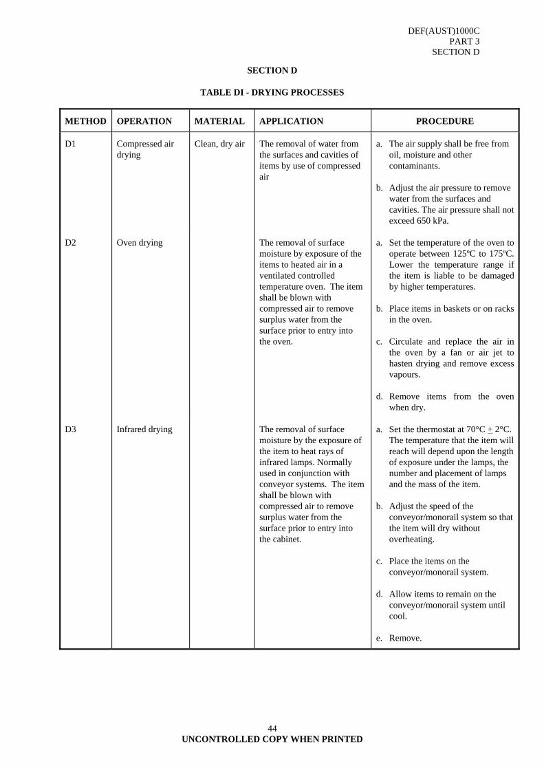
DEF(AUST)1000C PART 3
SECTION D
UNCONTROLLED COPY WHEN PRINTED
44
SECTION D
TABLE DI - DRYING PROCESSES
METHOD OPERATION MATERIAL APPLICATION PROCEDURE
D1 Compressed air drying
Clean, dry air The removal of water from the surfaces and cavities of items by use of compressed air
a. The air supply shall be free from oil, moisture and other contaminants.
b. Adjust the air pressure to remove
water from the surfaces and cavities. The air pressure shall not exceed 650 kPa.
D2 Oven drying The removal of surface moisture by exposure of the items to heated air in a ventilated controlled temperature oven. The item shall be blown with compressed air to remove surplus water from the surface prior to entry into the oven.
a. Set the temperature of the oven to operate between 125ºC to 175ºC. Lower the temperature range if the item is liable to be damaged by higher temperatures.
b. Place items in baskets or on racks
in the oven. c. Circulate and replace the air in
the oven by a fan or air jet to hasten drying and remove excess vapours.
d. Remove items from the oven
when dry.
D3 Infrared drying The removal of surface moisture by the exposure of the item to heat rays of infrared lamps. Normally used in conjunction with conveyor systems. The item shall be blown with compressed air to remove surplus water from the surface prior to entry into the cabinet.
a. Set the thermostat at 70°C + 2°C. The temperature that the item will reach will depend upon the length of exposure under the lamps, the number and placement of lamps and the mass of the item.
b. Adjust the speed of the
conveyor/monorail system so that the item will dry without overheating.
c. Place the items on the
conveyor/monorail system. d. Allow items to remain on the
conveyor/monorail system until cool.
e. Remove.
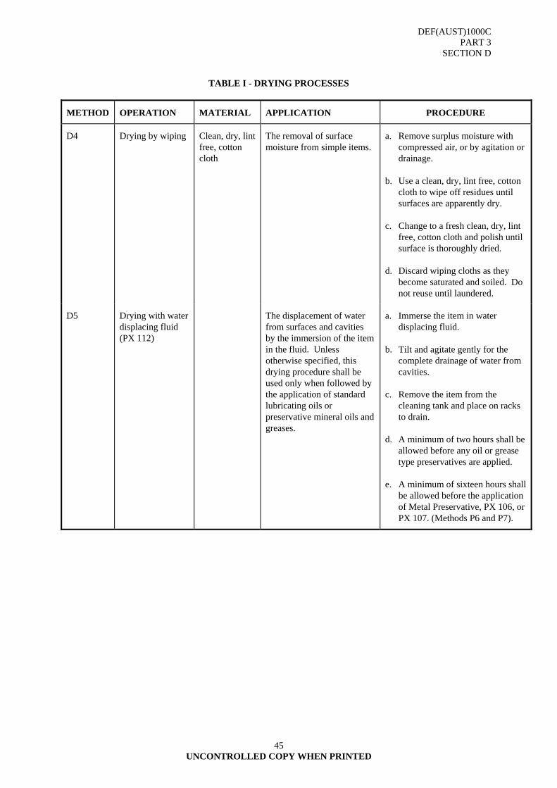
DEF(AUST)1000C PART 3
SECTION D
UNCONTROLLED COPY WHEN PRINTED
45
TABLE I - DRYING PROCESSES
METHOD OPERATION MATERIAL APPLICATION PROCEDURE
D4 Drying by wiping Clean, dry, lint free, cotton cloth
The removal of surface moisture from simple items.
a. Remove surplus moisture with compressed air, or by agitation or drainage.
b. Use a clean, dry, lint free, cotton
cloth to wipe off residues until surfaces are apparently dry.
c. Change to a fresh clean, dry, lint
free, cotton cloth and polish until surface is thoroughly dried.
d. Discard wiping cloths as they
become saturated and soiled. Do not reuse until laundered.
D5 Drying with water displacing fluid (PX 112)
The displacement of water from surfaces and cavities by the immersion of the item in the fluid. Unless otherwise specified, this drying procedure shall be used only when followed by the application of standard lubricating oils or preservative mineral oils and greases.
a. Immerse the item in water displacing fluid.
b. Tilt and agitate gently for the
complete drainage of water from cavities.
c. Remove the item from the
cleaning tank and place on racks to drain.
d. A minimum of two hours shall be
allowed before any oil or grease type preservatives are applied.
e. A minimum of sixteen hours shall
be allowed before the application of Metal Preservative, PX 106, or PX 107. (Methods P6 and P7).
DEF(AUST)1000C PART 3
SECTION E
46 UNCONTROLLED COPY WHEN PRINTED
SECTION E - TECHNICAL REQUIREMENTS FOR PROTECTION DURING STORAGE – PRESERVATION
1. GENERAL
1.1 This section covers the methods of preservation. The principle materials used, either alone or in combination, in the preservation of material are:
a. temporary protectives;
b. preservatives;
c. vapour phase inhibitors;
d. primary wrapping;
e. barriers;
f. desiccants.
1.2 The approved techniques used in the preservation of materiel are classified, for ease of reference, into the five broad groups listed below:
Method 0 Employing no preservation.
Method I Employing a temporary protective preservative or a vapour phase inhibitor.
Method IC Employing a waterproof barrier. The materiel may be treated with a temporary protective.
Method IA Employing a water-vapourproof barrier.
Method II Employing a desiccant within a water-vapourproof or water-vapour-resistant barrier.
1.2.1 In any of the above methods a primary wrapping may be employed.
WARNING
A knowledge of the hazards involved with preservation materials should be the foremost principle.
Personal injury can result from lack of attention to the proper use and cautions to be observed when using preservation materials.
If manufacturer's recommendations and the precautions cited in the relevant statutory regulations are carefully observed, no ill effects to personnel should occur.
When using preservation materials in preservation plants, the necessary protective clothing and devices shall be worn.
1.3 More detailed information on the hazards and endorsement procedures associated with each product may be obtained through: DPAP - Defence Petroleum and Allied Products Joint Fuels and Lubricants Agency (JFLA), Level 3, Defence Plaza, 270 Pitt Street, Sydney 2000
: 02 9377 2111 FAX: 02 9377 3349
AL2
DEF(AUST)1000C PART 3
SECTION E
UNCONTROLLED COPY WHEN PRINTED
47
2. MATERIALS
2.1 Preservation
2.1.1 The fact that an item has been cleaned and dried does not ensure that it will remain free from deterioration. In fact these processes increase the potential for damage by exposing the surfaces to the direct attack of air, water, sunlight, living organisms, temperature changes and ageing. In most cases deterioration is chemical change but it may also be a physical change such as deformation of rubber or plastic items. Organic materials such as wood, leather, fabrics, rubber and plastic are affected by micro organisms, insects, heat, sunlight and extremes of humidity. Inorganic materials such as glass, metal, quartz and graphite are attacked by chemical actions of gases, water and sunlight.
2.2 Preservatives
2.2.1 Preservatives are materials, compounds or substances applied to an item to protect it from deterioration. The composition of the item material indicates the type of preservative necessary to prevent deterioration.
2.2.1.1 Permanent Protection. A permanent preservative is applied to items in the course of manufacture with the intent of providing continuous maintenance free protection to the item or specific areas of the item. Permanent preservatives shall not be removed or their quality depreciated by the processes of cleaning, drying or finishing.
2.2.1.2 Temporary Protective for Metallic Items. Temporary corrosion preventives for metallic items shall be shown in TABLE I of this Section.
2.2.1.3 Temporary Protectives for Non Metallic Items. Non metallic items are liable to attack by bacteria, fungi and pests. Treatment to prevent deterioration is frequently given during manufacture. When an item has not been so treated it may be necessary to apply a temporary protective as shown in TABLE II.
2.3 Methods of Preservation.
Unless otherwise specified, preservation shall be accomplished by one or more of the methods detailed as follows:
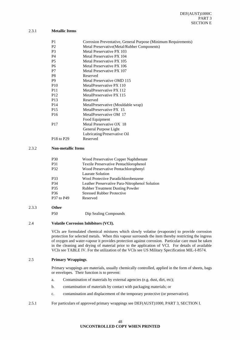
DEF(AUST)1000C PART 3
SECTION E
UNCONTROLLED COPY WHEN PRINTED
48
2.3.1 Metallic Items
P1 Corrosion Preventative, General Purpose (Minimum Requirements) P2 Metal Preservative(Metal/Rubber Components) P3 Metal Preservative PX 103 P4 Metal Preservative PX 104 P5 Metal Preservative PX 105 P6 Metal Preservative PX 106 P7 Metal Preservative PX 107 P8 Reserved P9 Metal Preservative OMD 115 P10 MetalPreservative PX 110 P11 MetalPreservative PX 112 P12 MetalPreservative PX 115 P13 Reserved P14 MetalPreservative (Mouldable wrap) P15 MetalPreservative PX 15 P16 MetalPreservative OM 17 Food Equipment P17 Metal Preservative OX 18 General Purpose Light Lubricating/Preservative Oil P18 to P29 Reserved
2.3.2 Non-metallic Items
P30 Wood Preservative Copper Naphthenate P31 Textile Preservative Pentachlorophenol P32 Wood Preservative Pentachlorophenyl Laurate Solution P33 Wool Protective Paradichlorobenzene P34 Leather Preservative Para-Nitrophenol Solution P35 Rubber Treatment Dusting Powder P36 Stressed Rubber Protective P37 to P49 Reserved
2.3.3 Other P50 Dip Sealing Compounds
2.4 Volatile Corrosion Inhibitors (VCI).
VCIs are formulated chemical mixtures which slowly volatise (evaporate) to provide corrosion protection for selected metals. When this vapour surrounds the item thereby restricting the ingress of oxygen and water-vapour it provides protection against corrosion. Particular care must be taken in the cleaning and drying of material prior to the application of VCI. For details of available VCIs see TABLE IV. For the utilization of the VCIs see US Military Specification MIL-I-8574.
2.5 Primary Wrappings.
Primary wrappings are materials, usually chemically controlled, applied in the form of sheets, bags or envelopes. Their function is to prevent:
a. Contamination of materials by external agencies (e.g. dust, dirt, etc);
b. contamination of materials by contact with packaging materials; or
c. contamination and displacement of the temporary protective (or preservative).
2.5.1 For particulars of approved primary wrappings see DEF(AUST)1000, PART 3, SECTION I.

DEF(AUST)1000C PART 3
SECTION E
UNCONTROLLED COPY WHEN PRINTED
49
2.5.2 It may be necessary to pad sharp edges or corners of items to be enclosed in these wrappings.
2.5.3 If a VCI paper is used a primary wrap may not be necessary.
2.6 Barriers
2.6.1 Barriers are materials, usually chemically controlled, used to enclose an item of material in a sealed bag or envelope. Their function is to minimize the ingress of water or water vapour. All are highly resistant to water but vary in their permeability to water-vapour. The bag or envelope may be placed around the item or may be in the form of a container liner. Where practicable, a loose liner should be used as a container liner, since it can be obtained pre-fabricated and is unlikely to be damaged by stresses on the container, but if this is not possible because of fitments inside the container, a fitted liner may be used. Construction details are given in DEF(AUST)1000, PART 3, SECTION G.
2.6.2 It may be necessary to pad sharp edges or corners of items to be enclosed in these barrier materials.
2.6.3 Barrier materials are classified as follows:
a. Waterproof. Offering a high degree of resistance to penetration of water (Refer DEF(AUST)1000, PART 3, SECTION H).
b. Greaseproof, Waterproof. Used as an intimate mouldable wrap for items coated with preservative oils and greases (Refer DEF(AUST)1000, PART 3. SECTION H).
c. Water-vapourproof. Offering a high resistance to the passage of water-vapour (Refer MIL-B-131).
2.7 Desiccants
Desiccants are substances, usually in granular form, which absorb moisture and retain it, at ambient temperatures. They are enclosed together with the item of materiel, within sealed water-vapour-resistant/proof barriers. The desiccant is normally supplied in fabric, e.g. linen bags, which should be disposed uniformly preferably using a number of small units rather than a single large unit, and it is important that they are secured in position to prevent damaging the material and to minimize the chance of desiccant dust escaping due to puncture of the bag.
2.7.1 The function of desiccants is to limit the relative humidity within the barrier, normally to a maximum value of 50 per cent.
2.7.2 The quantity of desiccant required is dependent upon the permeability of the barrier material to water-vapour, the amount of moisture enclosed within the barrier at the time of sealing and the duration for which protection is required (see APPENDIX A)
2.7.3 For information on the use of humidity indicators see APPENDIX B. 3. SELECTION AND METHOD OF PRESERVATION
3.1 The selection of the method of preservation shall be based upon the following factors:
a. the susceptibility of the materiel to deterioration from climatic hazards as determined by the materials from which it is made and any protective finishes, such as paint, applied during manufacture;
b. the complexity of construction of the item;
c. the size, mass and shape of the item;
d. the function of the materiel (including such considerations as the critical nature of its purpose and whether some measure of deterioration can be tolerated);
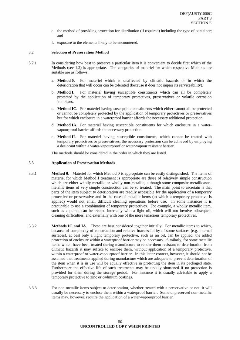
DEF(AUST)1000C PART 3
SECTION E
UNCONTROLLED COPY WHEN PRINTED
50
e. the method of providing protection for distribution (if required) including the type of container; and
f. exposure to the elements likely to be encountered.
3.2 Selection of Preservation Method
3.2.1 In considering how best to preserve a particular item it is convenient to decide first which of the Methods (see 1.2) is appropriate. The categories of materiel for which respective Methods are suitable are as follows:
a. Method 0. For materiel which is unaffected by climatic hazards or in which the deterioration that will occur can be tolerated (because it does not impair its serviceability).
b. Method I. For materiel having susceptible constituents which can all be completely protected by the application of temporary protectives, preservatives or volatile corrosion inhibitors.
c. Method IC. For materiel having susceptible constituents which either cannot all be protected or cannot be completely protected by the application of temporary protectives or preservatives but for which enclosure in a waterproof barrier affords the necessary additional protection.
d. Method IA. For materiel having susceptible constituents for which enclosure in a water-vapourproof barrier affords the necessary protection.
e. Method II. For materiel having susceptible constituents, which cannot be treated with temporary protectives or preservatives, the necessary protection can be achieved by employing a desiccant within a water-vapourproof or water-vapour resistant barrier.
The methods should be considered in the order in which they are listed.
3.3 Application of Preservation Methods
3.3.1 Method 0. Materiel for which Method 0 is appropriate can be easily distinguished. The items of materiel for which Method I treatment is appropriate are those of relatively simple construction which are either wholly metallic or wholly non-metallic, although some composite metallic/non-metallic items of very simple construction can be so treated. The main point to ascertain is that parts of the item subject to deterioration are readily accessible for the application of a temporary protective or preservative and in the case of metallic items (to which a temporary protective is applied) would not entail difficult cleaning operations before use. In some instances it is practicable to use a combination of temporary protectives. For example, a wholly metallic item, such as a pump, can be treated internally with a light oil, which will not involve subsequent cleaning difficulties, and externally with one of the more tenacious temporary protectives.
3.3.2 Methods IC and IA. These are best considered together initially. For metallic items to which, because of complexity of construction and relative inaccessibility of some surfaces (e.g. internal surfaces), at best only a light temporary protective, such as an oil, can be applied, the added protection of enclosure within a waterproof barrier may be necessary. Similarly, for some metallic items which have been treated during manufacture to render them resistant to deterioration from climatic hazards it may suffice to enclose them, without application of a temporary protective, within a waterproof or water-vapourproof barrier. In this latter context, however, it should not be assumed that treatments applied during manufacture which are adequate to prevent deterioration of the item when it is in use will be equally effective in protecting the item in its packaged state. Furthermore the effective life of such treatments may be unduly shortened if no protection is provided for them during the storage period. For instance it is usually advisable to apply a temporary protective to zinc or cadmium coatings.
3.3.3 For non-metallic items subject to deterioration, whether treated with a preservative or not, it will usually be necessary to enclose them within a waterproof barrier. Some unpreserved non-metallic items may, however, require the application of a water-vapourproof barrier.
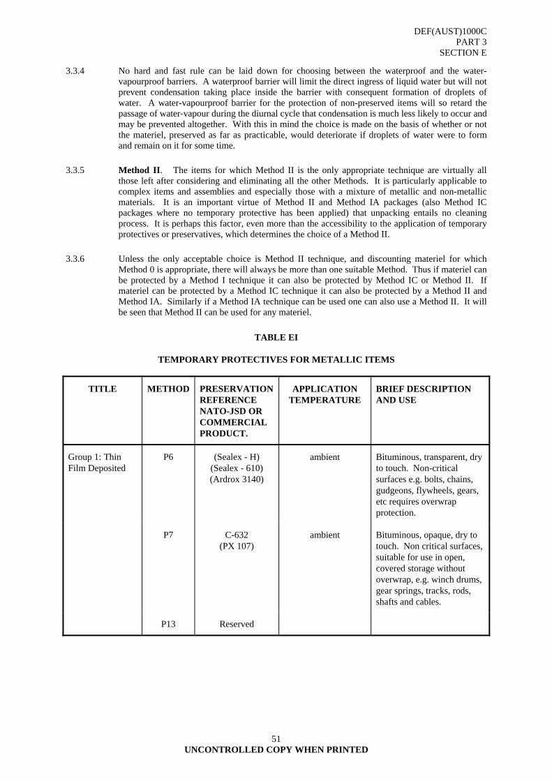
DEF(AUST)1000C PART 3
SECTION E
UNCONTROLLED COPY WHEN PRINTED
51
3.3.4 No hard and fast rule can be laid down for choosing between the waterproof and the water-vapourproof barriers. A waterproof barrier will limit the direct ingress of liquid water but will not prevent condensation taking place inside the barrier with consequent formation of droplets of water. A water-vapourproof barrier for the protection of non-preserved items will so retard the passage of water-vapour during the diurnal cycle that condensation is much less likely to occur and may be prevented altogether. With this in mind the choice is made on the basis of whether or not the materiel, preserved as far as practicable, would deteriorate if droplets of water were to form and remain on it for some time.
3.3.5 Method II. The items for which Method II is the only appropriate technique are virtually all those left after considering and eliminating all the other Methods. It is particularly applicable to complex items and assemblies and especially those with a mixture of metallic and non-metallic materials. It is an important virtue of Method II and Method IA packages (also Method IC packages where no temporary protective has been applied) that unpacking entails no cleaning process. It is perhaps this factor, even more than the accessibility to the application of temporary protectives or preservatives, which determines the choice of a Method II.
3.3.6 Unless the only acceptable choice is Method II technique, and discounting materiel for which Method 0 is appropriate, there will always be more than one suitable Method. Thus if materiel can be protected by a Method I technique it can also be protected by Method IC or Method II. If materiel can be protected by a Method IC technique it can also be protected by a Method II and Method IA. Similarly if a Method IA technique can be used one can also use a Method II. It will be seen that Method II can be used for any materiel.
TABLE EI
TEMPORARY PROTECTIVES FOR METALLIC ITEMS
TITLE METHOD PRESERVATION REFERENCE NATO-JSD OR COMMERCIAL PRODUCT.
APPLICATION TEMPERATURE
BRIEF DESCRIPTION AND USE
Group 1: Thin Film Deposited
P6 (Sealex - H) (Sealex - 610) (Ardrox 3140)
ambient Bituminous, transparent, dry to touch. Non-critical surfaces e.g. bolts, chains, gudgeons, flywheels, gears, etc requires overwrap protection.
P7 C-632 (PX 107)
ambient Bituminous, opaque, dry to touch. Non critical surfaces, suitable for use in open, covered storage without overwrap, e.g. winch drums, gear springs, tracks, rods, shafts and cables.
P13 Reserved
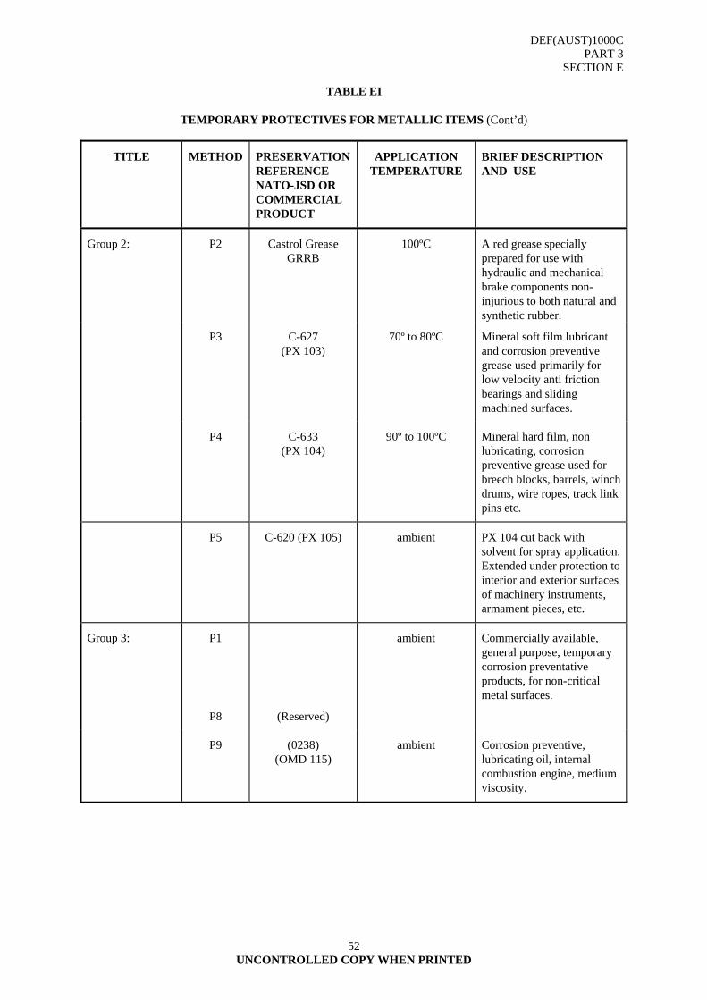
DEF(AUST)1000C PART 3
SECTION E
UNCONTROLLED COPY WHEN PRINTED
52
TABLE EI
TEMPORARY PROTECTIVES FOR METALLIC ITEMS (Cont’d)
TITLE METHOD PRESERVATION REFERENCE NATO-JSD OR COMMERCIAL PRODUCT
APPLICATION TEMPERATURE
BRIEF DESCRIPTION AND USE
Group 2: P2 Castrol Grease GRRB
100ºC A red grease specially prepared for use with hydraulic and mechanical brake components non- injurious to both natural and synthetic rubber.
P3 C-627 (PX 103)
70º to 80ºC Mineral soft film lubricant and corrosion preventive grease used primarily for low velocity anti friction bearings and sliding machined surfaces.
P4 C-633 (PX 104)
90º to 100ºC Mineral hard film, non lubricating, corrosion preventive grease used for breech blocks, barrels, winch drums, wire ropes, track link pins etc.
P5 C-620 (PX 105) ambient PX 104 cut back with solvent for spray application. Extended under protection to interior and exterior surfaces of machinery instruments, armament pieces, etc.
Group 3: P1 ambient Commercially available, general purpose, temporary corrosion preventative products, for non-critical metal surfaces.
P8 (Reserved)
P9 (0238) (OMD 115)
ambient Corrosion preventive, lubricating oil, internal combustion engine, medium viscosity.
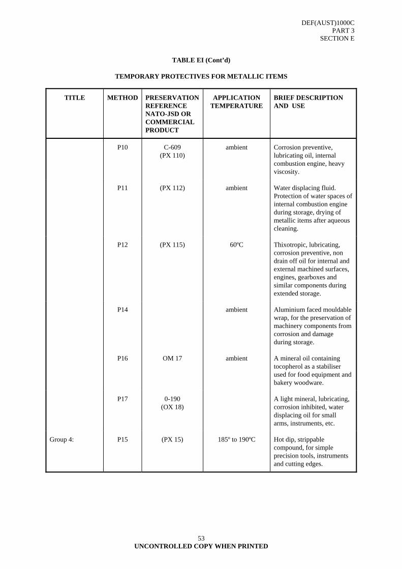
DEF(AUST)1000C PART 3
SECTION E
UNCONTROLLED COPY WHEN PRINTED
53
TABLE EI (Cont’d)
TEMPORARY PROTECTIVES FOR METALLIC ITEMS
TITLE METHOD PRESERVATION REFERENCE NATO-JSD OR COMMERCIAL PRODUCT
APPLICATION TEMPERATURE
BRIEF DESCRIPTION AND USE
P10 C-609 (PX 110)
ambient Corrosion preventive, lubricating oil, internal combustion engine, heavy viscosity.
P11 (PX 112) ambient Water displacing fluid. Protection of water spaces of internal combustion engine during storage, drying of metallic items after aqueous cleaning.
P12 (PX 115) 60ºC Thixotropic, lubricating, corrosion preventive, non drain off oil for internal and external machined surfaces, engines, gearboxes and similar components during extended storage.
P14 ambient Aluminium faced mouldable wrap, for the preservation of machinery components from corrosion and damage during storage.
P16 OM 17 ambient A mineral oil containing tocopherol as a stabiliser used for food equipment and bakery woodware.
P17 0-190 (OX 18)
A light mineral, lubricating, corrosion inhibited, water displacing oil for small arms, instruments, etc.
Group 4: P15 (PX 15) 185º to 190ºC Hot dip, strippable compound, for simple precision tools, instruments and cutting edges.
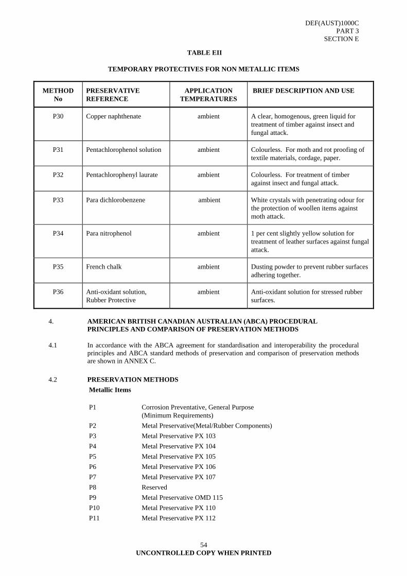
DEF(AUST)1000C PART 3
SECTION E
UNCONTROLLED COPY WHEN PRINTED
54
TABLE EII
TEMPORARY PROTECTIVES FOR NON METALLIC ITEMS
METHOD No
PRESERVATIVE REFERENCE
APPLICATION TEMPERATURES
BRIEF DESCRIPTION AND USE
P30 Copper naphthenate ambient A clear, homogenous, green liquid for treatment of timber against insect and fungal attack.
P31 Pentachlorophenol solution ambient Colourless. For moth and rot proofing of textile materials, cordage, paper.
P32 Pentachlorophenyl laurate ambient Colourless. For treatment of timber against insect and fungal attack.
P33 Para dichlorobenzene ambient White crystals with penetrating odour for the protection of woollen items against moth attack.
P34 Para nitrophenol ambient 1 per cent slightly yellow solution for treatment of leather surfaces against fungal attack.
P35 French chalk ambient Dusting powder to prevent rubber surfaces adhering together.
P36 Anti-oxidant solution, Rubber Protective
ambient Anti-oxidant solution for stressed rubber surfaces.
4. AMERICAN BRITISH CANADIAN AUSTRALIAN (ABCA) PROCEDURAL
PRINCIPLES AND COMPARISON OF PRESERVATION METHODS
4.1 In accordance with the ABCA agreement for standardisation and interoperability the procedural principles and ABCA standard methods of preservation and comparison of preservation methods are shown in ANNEX C.
4.2 PRESERVATION METHODS Metallic Items P1 Corrosion Preventative, General Purpose
(Minimum Requirements) P2 Metal Preservative(Metal/Rubber Components) P3 Metal Preservative PX 103 P4 Metal Preservative PX 104 P5 Metal Preservative PX 105 P6 Metal Preservative PX 106 P7 Metal Preservative PX 107 P8 Reserved P9 Metal Preservative OMD 115 P10 Metal Preservative PX 110 P11 Metal Preservative PX 112

DEF(AUST)1000C PART 3
SECTION E
UNCONTROLLED COPY WHEN PRINTED
55
P12 Metal Preservative PX 115 P13 Reserved P14 Metal Preservative (Mouldable wrap) P15 Metal Preservative PX 15 P16 Metal Preservative OM 17 Food Equipment P17 Metal Preservative OX 18 General Purpose Light Lubricating/Preservative Oil P18 to P29 Reserved
Non-Metallic Items
P31 Textile Preservative Pentachlorophenol
Solution P32 Wood Preservative Pentachlorophenyl
Laurate P33 Wool Protective Paradichlorobenzene P34 Leather Preservative Para-Nitrophenol
Solution P35 Rubber Treatment Dusting Powder P36 Stressed Rubber Protective P37 P49
Reserved
Other P50 Dip Sealing Compounds
DEF(AUST)1000C PART 3
SECTION E
UNCONTROLLED COPY WHEN PRINTED
56
4.3 PRESERVATION - METHOD P1
4.3.1 CORROSION PREVENTIVE, GENERAL PURPOSE
4.3.1.1 Specification. DEF(AUST)1000C, PART 14, Section B - Temporary Corrosion Preventative, General Purpose; (Minimum Requirements)
4.3.1.2 Composition
TYPE A an asphaltic compound dissolved in petroleum solvents, with inhibitors, which on application dries to a tough, thin and opaque film; or
TYPE B highly refined mineral lubrication oil containing corrosion inhibitors and additives which on application leaves a thin and uniform protective coating of oil.
4.3.1.3 Characteristics
Flash point °C Both products TYPES A & B should have a flash point not less that 37°C.
Salt spray 500 hours duration
Humidity 500 hours duration
4.3.1.4 Description. For commercially available, general purpose, corrosion preventative products.
4.3.1.5 Procedure. To be easily applied by dipping, spraying, brushing or flow coating
4.3.1.6 Removal. Is to be easily removed by an appropriate method, where applicable, and should retain this property when the product film has aged.
4.3.1.7 Uses. For the protection of non-critical ferrous and non-ferrous metal surfaces of equipment and component spare parts. The product, when required should protect items for a minimum of one (1) year for short-term storage, and a minimum period of three (3) years for long-term storage.
4.3.1.8 Handling and Safety Precautions.
TYPE A: Refer, 1000, SECTION C, TABLE I, Group A, of this document and the ADG Code, Class 3. Flammable Liquids.
TYPE B: Refer, 1000, SECTION C, TABLE 1, Group C, of this document and the ADG Code, Class 3. Flammable Liquids.
DEF(AUST)1000C PART 3
SECTION E
UNCONTROLLED COPY WHEN PRINTED
57
4.4 PRESERVATION - METHOD P2
4.4.1 METAL PRESERVATION (Metal/Rubber Components)
4.4.1.1 Specification. Commercial - Castrol GRRB or equivalent
4.4.1.2 Description. A soft film grease protective consisting of a uniform mixture of castor oil and lead stearate.
4.4.1.3 Procedure. Applied by brushing or smearing the metal surfaces. May be applied by hot dipping at about 100°C. Immersion time should be kept short to avoid damage to rubber components.
4.4.1.4 Removal. Remove surplus grease from rubber surfaces using a clean, dry, lint free, cotton cloth. Solvents shall not be used.
4.4.1.5 Uses. Hydraulic and mechanical brake components, non-injurious to both natural and synthetic rubber.
4.4.1.6 NATO Stock Number 500 g Can 9150-66-093-8343 Army, RAAF NOTE: Supersedes PX 12 for RAN purposes.
DEF(AUST)1000C PART 3
SECTION E
UNCONTROLLED COPY WHEN PRINTED
58
4.5 PRESERVATION - METHOD P3
4.5.1 METAL PRESERVATION C-627 (PX 103)
4.5.2 Specification. MIL-C-11796C - Class 3 - Corrosion Preventive Compound, Petrolatum, Hot Application.
4.5.3 Composition. High melting point petrolatum containing corrosion inhibitors.
4.5.4 Characteristics
Penetration, unworked 200 - 250 Melting point, °C 57 (min) Flash point, C.O.C. °C 177 (min)
4.5.5 Description. A dual lubricant and corrosion preventive grease which leaves a soft greasy film upon setting.
4.5.6 Procedure. Applied either by brushing at room temperature or by dipping in the molten state at temperatures between 70°C to 80°C. The normal application is by dipping unless otherwise stated in the specification. The material shall be allowed to cool and set before handling and overwrapping.
4.5.7 Removal. Removal shall be by the use of a solvent (Method C2 or C4, DEF(AUST)1000, PART 3, SECTION).
4.5.8 Uses. Employed primarily as a corrosion preventive for low viscosity, anti-friction bearings and sliding machined surfaces, aircraft spare parts and certain weapons.
4.5.9 Handling and Safety Precautions.
Refer: DEF(AUST)1000, PART 3, SECTION C, TABLE I, Group D, of this document and the ADG Code, Class 3. Flammable Liquids.
4.5.10 NATO Stock Number.
35 lb Container 8030-00-285-1570 N,A,R
NOTE: Supersedes PX 6, PX 7 for RAAF purposes.
4.5.11 Known Supplier/s C-627 (PX 103) Castrol Braycote 248 Valvoline Tectyl 437, or equivalent.
DEF(AUST)1000C PART 3
SECTION E
UNCONTROLLED COPY WHEN PRINTED
59
4.6 PRESERVATION - METHOD P4
4.6.1 METAL PRESERVATIVE C-633 (PX 104)
4.6.1.1 Specification. MIL-C-11796C - Class 1 Corrosion Preventive Compound, Petrolatum, Hot Application.
4.6.1.2 Composition. Suitable inhibitors in a modified petroleum base.
4.6.1.3 Characteristics
Melting point, °C 68 (min) Penetration, unworked 30 - 80 Flash point, C.O.C. °C 177 (min)
Must pass protection tests using mild steel panels subjected to high temperature and humidity.
4.6.1.4 Description. Amber coloured, with suitable inhibitors in a modified petrolatum base. Not normally regarded as having lubricating properties.
4.6.1.5 Procedure. Applied by dipping or brushing from a bath of material heated between 90°C to 100°C. The material shall be allowed to cool and set before handling and overwrapping.
4.6.1.6 Removal. Removal shall be by the use of a solvent (Method C2 or C4, SECTION C).
4.6.1.7 Uses. For the protection of external metal surfaces of robust construction e.g. gun barrels, breech blocks, winch drums and wire ropes, track link pins, etc. Preferably covered with a barrier material to exclude dirt and water.
4.6.1.8 Handling and Safety Precautions.
Refer: SECTION C, TABLE I, Group D, of this document, and the ADG Code, Class 3. Flammable Liquids.
4.6.1.9 NATO Stock Numbers 020 kg Drum 8030-66-035-7682 Army
2.5 kg Can 8030-66-086-8980 Navy, Army, RAAF
4.6.1.10 Known Supplier/s
C-633 (PX 104) Castrol Braycote 202
Valvoline Tectyl 435, or equivalent

DEF(AUST)1000C PART 3
SECTION E
UNCONTROLLED COPY WHEN PRINTED
60
4.7 PRESERVATION - METHOD P5
4.7.1 METAL PRESERVATIVE C-620 (PX 105)
4.7.1.1 Specification. MIL-C-16173D, - Grade 2 - Corrosion Preventive Compound, Solvent Cutback, Cold-application.
4.7.1.2 Composition. Soft film forming materials in a volatile solvent.
4.7.1.3 Characteristics
Flash point, P.M.C.C. °C 38 (min) Drying time, hours 4 (max)
Must pass protection tests using mild steel panels subjected to high temperature and sea-water immersion and be completely miscible with lubricating oil.
4.7.1.4 Description. Amber coloured with suitable inhibitors in a modified petrolatum base with a volatile solvent. Forms a soft film on the evaporation of the solvent. Not normally regarded as having lubricating properties.
4.7.1.5 Procedure. Applied at ambient temperatures by dipping, spraying, brushing or flow coating. The normal application shall be by dipping and spraying. The material shall be air dried and allowed to fully set before handling and/or overwrapping.
4.7.1.6 Removal. Removal shall be by the use of a solvent (Method C2 or C4, DEF(AUST)1000, PART 3, SECTION C).
4.7.1.7 Method of Removal. By kerosene.
4.7.1.8 Uses. For the protection of interior and exterior surfaces e.g., cylinder bores, valve mechanisms, exterior surfaces of machinery instruments, armament pieces and other similar assemblies. May be used on external surfaces with an overwrap barrier material.
4.7.1.9 Handling and Safety Precautions.
Refer: DEF(AUST)1000, PART 3, SECTION C, TABLE I, Group A, of this document, and the ADG Code, Class 3. Flammable Liquids.
4.7.1.10 NATO Stock Numbers
25 L Drum 8030-66-086-8904 Navy, Army, RAAF 4 L Can 8030-66-086-8905 Army, RAAF 1 (US) Gal Can 8030-00-244-1297 Navy
4.7.1.11 Known Supplier/s
C-620 (PX 105) Castrol Braycote 137 Valvoline Tectyl 502C, or equivalent
DEF(AUST)1000C PART 3
SECTION E
UNCONTROLLED COPY WHEN PRINTED
61
4.8 PRESERVATION - METHOD P6
4.8.1 METAL PRESERVATIVE (Corrosion Preventive Compound, Hard Film)
4.8.1.1 Specification. Commercial. Sealex - H Sealex - 610 Ardox - 3140
4.8.1.2 Description. An asphaltic compound dissolved in petroleum solvents, which dries to a hard, thin, transparent film.
4.8.1.3 Procedure. Applied at ambient temperature by dipping, spraying, brushing or flow coating. The normal application shall be dipping. The materials shall be allowed to dry fully before handling.
The material shall be maintained at a viscosity of 200 x 10-6 m²/s at 21°C. The viscosity shall be adjusted by the addition of Industrial Solvent A.
4.8.1.4 Removal. Removal shall be by the use of a solvent (Method C2 or C4, DEF(AUST)1000, PART 3, SECTION C).
4.8.1.5 Uses. For the treatment of non-critical metal surfaces and spare parts where a transparent, thin, hard, tough, elastic and non-stick film is required. It shall not be used where there is a requirement for a corrosion preventive which has miscibility with a standard lubricating oils, e.g. bolts, chains, gudgeons, flywheels, gears, etc, requires overwrap protection.
4.8.1.6 NATO Stock Number
20 L Drum 8030-66-088-7457 Army, Navy, RAAF
NOTE: Supersedes PX 106 for Navy purposes.
DEF(AUST)1000C PART 3
SECTION E
UNCONTROLLED COPY WHEN PRINTED
62
4.9 PRESERVATION - METHOD P7
4.9.1 METAL PRESERVATIVE C-632 (PX 107)
4.9.1.1 Specification. MIL-C-16173D - Grade 1 - Corrosion Preventive Compound, Solvent Cutback, Cold-application.
4.9.1.2 Composition. Corrosion preventives dissolved in a petroleum solvent.
4.9.1.3 Characteristics Flash point, P.M.C.C. °C 38 (min) Flow point °C 79 (min)
Must pass corrosion protection tests.
4.9.1.4 Description. An asphaltic compound dissolved in petroleum solvents, which dries to a hard, thin, tough, opaque film.
4.9.1.5 Procedure. Applied at ambient temperature by dipping, spraying, brushing or flow coating. The normal application shall be dipping. The materials shall be allowed to dry fully before handling.
4.9.1.6 The material shall be maintained at a viscosity of 200 x 10-6 m²/s at 21°C. The viscosity shall be adjusted by the addition of Industrial Solvent A.
4.9.1.7 Removal. Removal shall be by the use of a solvent (Method C2 or C4, DEF(AUST)1000, PART 3, SECTION C).
4.9.1.8 Uses. Treatment of non-critical metal surfaces and spare parts where a thin, hard, tough, elastic and non-sticky film is required and where film transparency is not essential. It shall not be used where there is a requirement for a corrosion preventive which has miscibility with standard lubricating oils. Suitable for use in open, covered storage without overwrap, e.g. winch drums, gear springs, track rods, shafts and cables.
4.9.1.9 Handling and Safety Precautions.
Refer: DEF(AUST)1000, PART 3, SECTION C, TABLE I, Group A, of this document, and the ADG Code, Class 3. Flammable Liquids.
4.9.1.10 NATO Stock Numbers
25 L Drum 8030-66-088-7305 Navy, Army, RAAF
4 L Can 8030-66-088-7306 Navy, Army, RAAF
4.9.1.11 Known Supplier/s
C-632 (PX 107) Castrol Braycote 103
Valvoline Tectyl 890 or equivalent
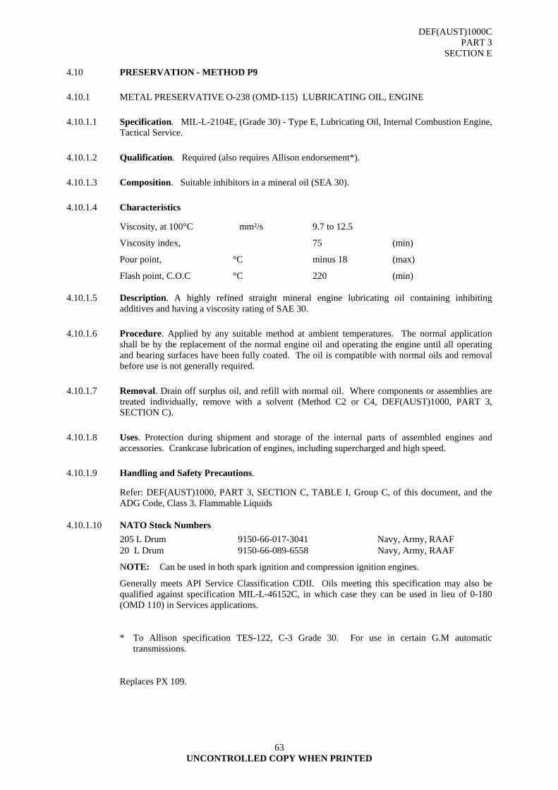
DEF(AUST)1000C PART 3
SECTION E
UNCONTROLLED COPY WHEN PRINTED
63
4.10 PRESERVATION - METHOD P9
4.10.1 METAL PRESERVATIVE O-238 (OMD-115) LUBRICATING OIL, ENGINE
4.10.1.1 Specification. MIL-L-2104E, (Grade 30) - Type E, Lubricating Oil, Internal Combustion Engine, Tactical Service.
4.10.1.2 Qualification. Required (also requires Allison endorsement*).
4.10.1.3 Composition. Suitable inhibitors in a mineral oil (SEA 30).
4.10.1.4 Characteristics
Viscosity, at 100°C mm²/s 9.7 to 12.5
Viscosity index, 75 (min)
Pour point, °C minus 18 (max)
Flash point, C.O.C °C 220 (min)
4.10.1.5 Description. A highly refined straight mineral engine lubricating oil containing inhibiting additives and having a viscosity rating of SAE 30.
4.10.1.6 Procedure. Applied by any suitable method at ambient temperatures. The normal application shall be by the replacement of the normal engine oil and operating the engine until all operating and bearing surfaces have been fully coated. The oil is compatible with normal oils and removal before use is not generally required.
4.10.1.7 Removal. Drain off surplus oil, and refill with normal oil. Where components or assemblies are treated individually, remove with a solvent (Method C2 or C4, DEF(AUST)1000, PART 3, SECTION C).
4.10.1.8 Uses. Protection during shipment and storage of the internal parts of assembled engines and accessories. Crankcase lubrication of engines, including supercharged and high speed.
4.10.1.9 Handling and Safety Precautions.
Refer: DEF(AUST)1000, PART 3, SECTION C, TABLE I, Group C, of this document, and the ADG Code, Class 3. Flammable Liquids
4.10.1.10 NATO Stock Numbers 205 L Drum 9150-66-017-3041 Navy, Army, RAAF 20 L Drum 9150-66-089-6558 Navy, Army, RAAF
NOTE: Can be used in both spark ignition and compression ignition engines.
Generally meets API Service Classification CDII. Oils meeting this specification may also be qualified against specification MIL-L-46152C, in which case they can be used in lieu of 0-180 (OMD 110) in Services applications.
* To Allison specification TES-122, C-3 Grade 30. For use in certain G.M automatic transmissions.
Replaces PX 109.
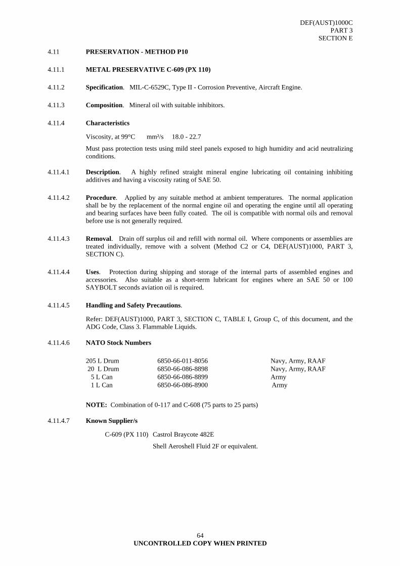
DEF(AUST)1000C PART 3
SECTION E
UNCONTROLLED COPY WHEN PRINTED
64
4.11 PRESERVATION - METHOD P10
4.11.1 METAL PRESERVATIVE C-609 (PX 110)
4.11.2 Specification. MIL-C-6529C, Type II - Corrosion Preventive, Aircraft Engine.
4.11.3 Composition. Mineral oil with suitable inhibitors.
4.11.4 Characteristics
Viscosity, at 99°C mm²/s 18.0 - 22.7
Must pass protection tests using mild steel panels exposed to high humidity and acid neutralizing conditions.
4.11.4.1 Description. A highly refined straight mineral engine lubricating oil containing inhibiting additives and having a viscosity rating of SAE 50.
4.11.4.2 Procedure. Applied by any suitable method at ambient temperatures. The normal application shall be by the replacement of the normal engine oil and operating the engine until all operating and bearing surfaces have been fully coated. The oil is compatible with normal oils and removal before use is not generally required.
4.11.4.3 Removal. Drain off surplus oil and refill with normal oil. Where components or assemblies are treated individually, remove with a solvent (Method C2 or C4, DEF(AUST)1000, PART 3, SECTION C).
4.11.4.4 Uses. Protection during shipping and storage of the internal parts of assembled engines and accessories. Also suitable as a short-term lubricant for engines where an SAE 50 or 100 SAYBOLT seconds aviation oil is required.
4.11.4.5 Handling and Safety Precautions.
Refer: DEF(AUST)1000, PART 3, SECTION C, TABLE I, Group C, of this document, and the ADG Code, Class 3. Flammable Liquids.
4.11.4.6 NATO Stock Numbers
205 L Drum 6850-66-011-8056 Navy, Army, RAAF 20 L Drum 6850-66-086-8898 Navy, Army, RAAF 5 L Can 6850-66-086-8899 Army 1 L Can 6850-66-086-8900 Army
NOTE: Combination of 0-117 and C-608 (75 parts to 25 parts)
4.11.4.7 Known Supplier/s
C-609 (PX 110) Castrol Braycote 482E
Shell Aeroshell Fluid 2F or equivalent.

DEF(AUST)1000C PART 3
SECTION E
UNCONTROLLED COPY WHEN PRINTED
65
4.12 PRESERVATION - METHOD P11
4.12.1 METAL PRESERVATIVE (PX 112)
4.12.1.1 Specification. Commercial: Water Displacing Fluid.
4.12.1.2 Composition. Protective and surface active materials dissolved in a volatile spirit.
4.12.1.3 Characteristics Viscosity, at 21°C mm²/s 5 (max) Flash point, Abel °C 35 (min) Pour point, (max)
Must pass specified water displacing and corrosion tests.
4.12.1.4 Description. Comprising of protective and surface active materials dissolved in a volatile spirit which deposits a thin non-drying film upon the evaporation of the solvent. The fluid displaces either salt or fresh water from rusted or unrusted metal surfaces.
4.12.1.5 Procedure. Applied at ambient temperature by dipping, spraying, or brushing of exterior surfaces and flushing of interior surfaces and after use a minimum period of 2 hours shall elapse before any lubricating and corrosion preventive oil or grease is applied and, sixteen hours before any hard dry film material is applied.
4.12.1.6 Removal. The residual oil is compatible with standard lubricating oils and greases. Removal is essential and shall be effected by a solvent. (Method C2 or C4, DEF(AUST)1000, PART 3, SECTION C).
4.12.1.7 Uses. For the protection of water spaces of an internal combustion engine during storage, the drying of a metallic item after aqueous cleaning process and the temporary protection of an item over short term close down periods, also used for the displacement of water from combustion chambers in a salvaged vehicle.
4.12.1.8 Handling and Safety Precautions.
Refer: DEF(AUST)1000, PART 3, SECTION C, TABLE I, Group A, of this document, and the ADG Code, Class 3. Flammable Liquids.
4.12.1.9 NATO Stock Numbers 205 L Drum 6850-66-023-9253 Navy, Army 20 L Drum 6850-66-088-7459 Navy, Army, RAAF 5 L Can 6850-66-088-7460 Navy, Army
NOTE: For spraying application use in conjunction with Atomizer, Hand Operated (NSN 4940-66-035-4940)
4.12.1.10 Known Qualified Supplier/s
PX 112 Mobil Mobilarma 245
CRC Chemicals CRC 5-56, or equivalent
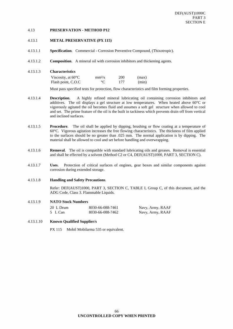
DEF(AUST)1000C PART 3
SECTION E
UNCONTROLLED COPY WHEN PRINTED
66
4.13 PRESERVATION - METHOD P12
4.13.1 METAL PRESERVATIVE (PX 115)
4.13.1.1 Specification. Commercial - Corrosion Preventive Compound, (Thixotropic).
4.13.1.2 Composition. A mineral oil with corrosion inhibitors and thickening agents.
4.13.1.3 Characteristics Viscosity, at 60°C mm²/s 200 (max) Flash point, C.O.C °C 177 (min)
Must pass specified tests for protection, flow characteristics and film forming properties.
4.13.1.4 Description. A highly refined mineral lubricating oil containing corrosion inhibitors and additives. The oil displays a gel structure at low temperatures. When heated above 60°C or vigorously agitated the oil becomes fluid and assumes a soft gel structure when allowed to cool and set. The prime feature of the oil is the built in tackiness which prevents drain off from vertical and inclined surfaces.
4.13.1.5 Procedure. The oil shall be applied by dipping, brushing or flow coating at a temperature of 60°C. Vigorous agitation increases the free flowing characteristics. The thickness of film applied to the surfaces should be no greater than .025 mm. The normal application is by dipping. The material shall be allowed to cool and set before handling and overwrapping.
4.13.1.6 Removal. The oil is compatible with standard lubricating oils and greases. Removal is essential and shall be effected by a solvent (Method C2 or C4, DEF(AUST)1000, PART 3, SECTION C).
4.13.1.7 Uses. Protection of critical surfaces of engines, gear boxes and similar components against corrosion during extended storage.
4.13.1.8 Handling and Safety Precautions.
Refer: DEF(AUST)1000, PART 3, SECTION C, TABLE I, Group C, of this document, and the ADG Code, Class 3. Flammable Liquids.
4.13.1.9 NATO Stock Numbers 20 L Drum 8030-66-088-7461 Navy, Army, RAAF 5 L Can 8030-66-088-7462 Navy, Army, RAAF
4.13.1.10 Known Qualified Supplier/s
PX 115 Mobil Mobilarma 535 or equivalent.

DEF(AUST)1000C PART 3
SECTION E
UNCONTROLLED COPY WHEN PRINTED
67
4.14 PRESERVATION - METHOD P13
(RESERVED)

DEF(AUST)1000C PART 3
SECTION E
UNCONTROLLED COPY WHEN PRINTED
68
4.15 PRESERVATION - METHOD P14
4.15.1 METAL PRESERVATIVE
4.15.1.1 Specification. Dockyard Material Specification No.159 - Heavy Duty Aluminium Faced Mouldable Wrap.
4.16 Composition
a. Aluminium Grade 1145-0.
b. Wax - neutral and microcrystalline with an initial melting point of 77°C, and shall contain zinc chromate as a surface acting corrosion inhibitor, viscostatic stabilisers, oxidation inhibitors and tackifying agents.
c. Woven Backing - shall be a fibre not lighter than 40/40/36b/32b nor heavier than 42/42/20s/20s.
4.16.1.1 Description. The Material shall consist of a single ply of aluminium sheet combined with a woven backing component by a compounded wax.
4.16.1.2 Procedure. Applied at ambient temperature by a wrapping or pressing into place.
4.16.1.3 Removal. By cutting and peeling off.
4.16.1.4 Uses. For the preservation of machinery components from corrosion and damage during storage.
4.16.1.5 NATO Stock Numbers
50 m Roll 5640-66-119-3033
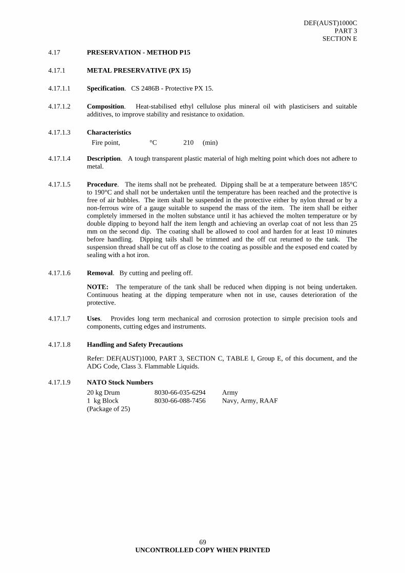
DEF(AUST)1000C PART 3
SECTION E
UNCONTROLLED COPY WHEN PRINTED
69
4.17 PRESERVATION - METHOD P15
4.17.1 METAL PRESERVATIVE (PX 15)
4.17.1.1 Specification. CS 2486B - Protective PX 15.
4.17.1.2 Composition. Heat-stabilised ethyl cellulose plus mineral oil with plasticisers and suitable additives, to improve stability and resistance to oxidation.
4.17.1.3 Characteristics Fire point, °C 210 (min)
4.17.1.4 Description. A tough transparent plastic material of high melting point which does not adhere to metal.
4.17.1.5 Procedure. The items shall not be preheated. Dipping shall be at a temperature between 185°C to 190°C and shall not be undertaken until the temperature has been reached and the protective is free of air bubbles. The item shall be suspended in the protective either by nylon thread or by a non-ferrous wire of a gauge suitable to suspend the mass of the item. The item shall be either completely immersed in the molten substance until it has achieved the molten temperature or by double dipping to beyond half the item length and achieving an overlap coat of not less than 25 mm on the second dip. The coating shall be allowed to cool and harden for at least 10 minutes before handling. Dipping tails shall be trimmed and the off cut returned to the tank. The suspension thread shall be cut off as close to the coating as possible and the exposed end coated by sealing with a hot iron.
4.17.1.6 Removal. By cutting and peeling off.
NOTE: The temperature of the tank shall be reduced when dipping is not being undertaken. Continuous heating at the dipping temperature when not in use, causes deterioration of the protective.
4.17.1.7 Uses. Provides long term mechanical and corrosion protection to simple precision tools and components, cutting edges and instruments.
4.17.1.8 Handling and Safety Precautions
Refer: DEF(AUST)1000, PART 3, SECTION C, TABLE I, Group E, of this document, and the ADG Code, Class 3. Flammable Liquids.
4.17.1.9 NATO Stock Numbers 20 kg Drum 8030-66-035-6294 Army 1 kg Block (Package of 25)
8030-66-088-7456 Navy, Army, RAAF
DEF(AUST)1000C PART 3
SECTION E
UNCONTROLLED COPY WHEN PRINTED
70
4.18 PRESERVATION - METHOD P16
4.18.1 PRESERVATIVE OIL, FOOD EQUIPMENT (OM 17)
4.18.1.1 Specification. DEF STAN 91-36/1.
4.18.1.2 Composition. Mineral oil which may contain not more than 10 parts per million of tocopherol, or butylated hydroxytoluene, as a stabilizer.
4.18.1.3 Characteristics. Transparent, colourless, tasteless and odourless. Viscosity, at 40°C mm²/s 12 - 15 Pour point, °C minus 18 (max) Flash point, P.M.C.C °C 150 (min)
The specification includes a test of absorption intensity by spectrophotometer.
4.18.1.4 Description. A water-white, tasteless and odourless non-toxic mineral oil containing not more than ten parts per million of tocopherol or butylated hydroxytoluene as a stabilizer.
4.18.1.5 Procedure. Applied by dipping, brushing, spraying or rubbing with a saturated cloth. The normal application shall be dipping for small components, spraying or brushing for large equipments and brushing or rubbing for woodware. The protective shall be applied to obtain an even film coating on all internal and external surfaces. The oil processes no setting or drying characteristics.
4.18.1.6 Removal. Removal is not essential.
4.18.1.7 Uses. Lubrication of bakery and canteen equipment and preservation of bakery woodware, tinned or of such complexity as to make subsequent cleaning difficult.
4.18.1.8 Handling and Safety Precautions
Refer: DEF(AUST)1000, PART 3, SECTION C, TABLE I, Group C, of this document, and the ADG Code, Class 3. Flammable Liquids.
4.18.1.9 NATO Stock Numbers
5 L Can 9150-66-088-7267 Army, Navy
NOTE: British Pharmacopoeia description is "Petrolatum Liquid Technical".
DEF(AUST)1000C PART 3
SECTION E
UNCONTROLLED COPY WHEN PRINTED
71
4.19 PRESERVATION - METHOD P17
4.19.1 METAL PRESERVATIVE LUBRICATING, CORROSION PREVENTIVE, GENERAL PURPOSE, LIGHT, 0-190 (OX 18)
4.19.1.1 Specification. VV-L-800C, Am 1 - Lubricating Oil, General Purpose, Preservative CS 3118 - Oil, Lubricating and Protective
4.19.1.2 Composition. Mineral oil with corrosion inhibiting and water displacing additives.
4.19.1.3 Characteristics. Viscosity, at 40°C mm²/s 12 (min) Viscosity, at minus 40°C mm²/s 7000 (max) Viscosity, at minus 54°C mm²/s 60000 (max) Pour point, °C minus 57 (max) Flash point, C.O.C °C 135 (min)
The specification includes tests of water displacement and water stability, oxidation stability and protection of steel.
4.19.1.4 Description. A light mineral oil with corrosion inhibiting water displacing additives.
4.19.1.5 Procedure. The normal application shall be dipping. Surplus material shall be allowed to drain and the residue to set before handling and overwrapping.
4.19.1.6 Removal. The oil is compatible with standard lubricating oils and greases. Removal shall be effected by a solvent (Method C2 or C4).
4.19.1.7 Uses. Lubrication and preservation of small arms, instruments at low and medium temperatures. Limited application for aircraft weapons.
4.19.1.8 Handling and Safety Precautions:
Refer: DEF(AUST)1000, PART 3, SECTION C, TABLE I, Group C, of this document, and the ADG Code, Class 3. Flammable Liquids.
4.19.1.9 NATO Stock Numbers: 20 L Drum 9150-66-083-9732 Army, RAAF 5 L Can 9150-66-083-9733 Navy, Army, RAAF
NOTE: Generally superseded in weapons lubrication by S-758 (PX 18) to MIL-L-63460.
4.19.1.10 Known Supplier/s
O-190 (OX 18) Castrol Braycote 300 or equivalent.
S-758 (PX 18) Brake Free Inc Brake Free CLP
Royal Lubricants Co Royco-463
Nycoil Aosyn-900, or equivalent.
DEF(AUST)1000C PART 3
SECTION E
UNCONTROLLED COPY WHEN PRINTED
72
4.20 PRESERVATION - METHOD P30
4.20.1 WOOD PRESERVATIVE COPPER NAPTHENATE
4.20.1.1 Specification. DEF STAN 68-9 - Copper Napthenate Solution
4.20.1.2 Description. The solution shall be a clear homogeneous liquid of deep green colour and shall be free from foreign matter. It shall consist of a solution of copper derivatives of naphthalenic acids in a petroleum distillate.
4.20.1.3 Procedure. The solution shall be applied by soaking, dipping, brushing or spraying without dilution. Protective clothing, gloves and eye shield shall be worn.
4.20.1.4 Uses. The solution shall be used for the preservation of seasoned timber, as oils will not penetrate green timber. The solution diluted may be used for the preservation of textiles.
NOTE: The toxicity rating exists and may cause irritation of the skin and conjunctiva.

DEF(AUST)1000C PART 3
SECTION E
UNCONTROLLED COPY WHEN PRINTED
73
4.21 PRESERVATION - METHOD P31
4.21.1 TEXTILE PRESERVATION PENTACHLOROPHENOL SOLUTION
4.21.1.1 Specification. AS 1604 - Pentachlorophenol Solution
4.21.1.2 Description. The solution consists of a 5 per cent (w/w) solution of pentachlorophenol in a solvent mix.
4.21.1.3 Procedure. Applied to textiles as a solution in a solvent using spirit or water. Materials shall be dipped, sprayed or brushed. Immersion time shall be not less than two minutes.
4.21.1.4 Uses. The moth and rot proofing of heavy and light textiles including felts, wool and cotton finishing, canvas, jute, ropes, twines, yarns, carpets and netting, paper, cork, leather, polyvinylchloride, nitrocellulose, rubber and combinations of these materials. The amount of PCPL on textile materials varies according to conditions of use. As a fungicide 0.5 per cent is adequate for temperature conditions and 2.0 per cent for tropical.
WARNING
Toxicity rating is high requiring protective dress, gloves, eye shield and chemical filter respirator. It is dangerous when heated to decomposition emitting highly toxic fumes of chlorides and continuous local exhaust ventilation shall be provided. Any skin contamination shall be washed off thoroughly with soap and water.
PCPL stored in low temperatures results in partial crystallisation of the fluid, when warmed the crystals melt and in no way detract from the effectiveness of the protection.
AL2
DEF(AUST)1000C PART 3
SECTION E
UNCONTROLLED COPY WHEN PRINTED
74
4.22 PRESERVATION - METHOD P32
4.22.1 WOOD PRESERVATIVE PENTACHLOROPHENYL LAURATE
4.22.1.1 Specification. DEF 177, or TT-W-572 Composition A - Pentachlorophenyl Laurate Solution.
4.22.1.2 Description. Pentachlorophenyl Laurate (synonym PCPL or LPCP) is a yellow brown, almost odourless, non-volatile liquid, free flowing at normal temperatures. It is not corrosive to common metals and alloys or harmful to plastics and rubber.
4.22.1.3 Procedure. Applied by dipping or brushing.
4.22.1.4 Uses. Preservation of timber products by simple non-pressure methods without heating. The treatment shall provide a moderate degree of resistance to shrinking and swelling, insects and fungi when exposed intermittently to damp conditions. The solution does not materially affect the colour of the wood.
WARNING
Toxicity rating is high requiring protective dress, gloves, eye shield and chemical filter respirator. It is dangerous when heated to decomposition emitting highly toxic fumes of chlorides and continuous local exhaust ventilation shall be provided. Any skin contamination shall be washed off thoroughly with soap and water.
PCPL stored in low temperatures results in partial crystallisation of the fluid, when warmed the crystals melt and in no way detract from the effectiveness of the protection.
AL2
DEF(AUST)1000C PART 3
SECTION E
UNCONTROLLED COPY WHEN PRINTED
75
4.23 PRESERVATION - METHOD P33
4.23.1 WOOL PROTECTIVE PARA DICHLOROBENZENE
4.23.1.1 Specification. Commercial - Para dichlorobenzene.
4.23.1.2 Description. An insecticide of white crystals with a penetrating odour.
4.23.1.3 Procedure. The material, in granular form, shall be evenly dispersed between each article, folds and between the top and bottom surfaces and the unit wrap. Application shall be at the rate of 160 g/m³.
4.23.1.4 Uses. For the protection of woollen items against moth attack.
NOTE: Its toxicity rating is moderate requiring the handler to use gloves and chemical filter respirator. The substance will react vigorously with oxidizing materials.
DEF(AUST)1000C PART 3
SECTION E
UNCONTROLLED COPY WHEN PRINTED
76
4.24 PRESERVATION - METHOD P34
4.24.1 LEATHER PRESERVATIVE PARA NITROPHENOL SOLUTION
4.24.1.1 Specification. CS 2282 Para nitrophenol Solution.
4.24.1.2 Description. Colourless to slightly yellow crystals. The solution shall consist of 1 per cent para nitrophenol crystals in methylated spirits, Industrial Grade II.
4.24.1.3 Procedure. Applied by brushing or spraying. Any preservative deposited upon non-leather surfaces shall be removed by wiping with a clean, dry, lint free, cotton cloth. The contaminated cloth shall be discarded after use.
4.24.1.4 Uses. The treatment of leather surfaces against microbiological attack.
WARNING
Toxicity rating is high. Chemical filter respirator and eye shields shall be worn. Continuous local exhaust ventilation shall be provided.
Alternative preservation compounds for leather are listed in TABLE III.
AL2
DEF(AUST)1000C PART 3
SECTION E
UNCONTROLLED COPY WHEN PRINTED
77
4.25 PRESERVATION - METHOD P35
4.25.1 RUBBER TREATMENT - DUSTING POWDER
4.25.1.1 Specification. DEF 179 Powder, Dusting for Rubber.
4.25.1.2 Description. Natural stearite (French chalk) or kaolin (China clay) in the form of fine white powder.
4.25.1.3 Procedure. Any suitable method.
4.25.1.4 Uses. Dusting a rubber item or rubber proofed fabric to prevent adhesion.

DEF(AUST)1000C PART 3
SECTION E
UNCONTROLLED COPY WHEN PRINTED
78
4.26 PRESERVATION - METHOD P36
4.26.1 STRESSED RUBBER PROTECTIVE
4.26.1.1 Specification. CS 3037 Solution Rubber Protective.
4.26.1.2 Procedure. Applied by brushing or spraying. The surface shall be thoroughly coated with protective and allowed to fully dry before handling and overwrapping.
4.26.1.3 Uses. For the treatment of stressed rubber supplies.
DEF(AUST)1000C PART 3
SECTION E
UNCONTROLLED COPY WHEN PRINTED
79
4.27 PRESERVATION - METHOD P50
4.27.1 DIP SEALING COMPOUNDS
4.27.1.1 This method covers dip sealing compounds, suitable for the packaging of Service stores.
4.27.2 REQUIREMENTS
4.27.2.1 The compounds covered by this Specification shall be non-toxic, water repellent and non-emulsifiable with water.
4.27.2.2 Tests
4.27.2.2.1 Stability. The stability of the compound shall be such that the residue remaining in the beaker shall be not greater than 0·5% when tested as specified in para 4.29.
4.27.2.2.2 Application Temperature. The compound shall be suitable for application by dipping or brushing at a temperature between 88º and 99ºC (190º and 210ºF).
4.27.2.2.3 Flexibility. The film of the compound shall show no signs of rupture, flaking or cracking after bonding around a 1/8 in. diameter rod at 0ºC (32ºF), when tested as specified in para 4.30.
4.27.2.2.4 Freedom from Corrosive Properties. The compound shall be non-corrosive to steel, copper and aluminium when tested as specified in para 4.31.
4.27.2.2.5 Transparency. The compound shall be sufficiently transparent for 10-point type to be easily readable through a film of weight as specified in paragraph 4.28.2.2.9.
4.27.2.2.6 Exposure to Dry Heat. The compound when subjected to a temperature of 63ºC (145ºF) as specified in Annex D shall exhibit the following properties:
a. The loss of film weight shall be not greater than 5%.
b. The package shall remain sealed without any indication of lifting of the flaps or overlap and no solid wax shall be removed when the base sheets are pulled from the package.
c. The base sheets shall be easily removable.
4.27.2.2.7 Moisture-Vapour Permeability. The film of the compound when subjected to the test specified in Annex E shall have a moisture-vapour permeability not greater than 6·0 grams per square metre per 24 hours (38ºC or 100ºF, 90% RH CaCl2).
4.27.2.2.8 Softening Point. The softening point of the compound when determined in accordance with ASTM Method E28-97 shall be not less than 155ºF.
4.27.2.2.9 Film Weight. The film weight per unit area when determined by the method specified in Appendix F shall be not less than 40 grams per square metre and not greater than 75 grams per square metre.
DEF(AUST)1000C PART 3
SECTION E
UNCONTROLLED COPY WHEN PRINTED
80
4.28 METHOD OF DETERMINATION OF STABILITY
4.28.1 A 20 gm sample of the sealing compound shall be placed in a weighed 400 ml beaker heated in a convection-current type oven at 99º ± 1ºC for 72 hours. The beaker shall then be removed from the oven and its contents visually examined while hot for separation into layers or sedimentation of sludge. The molten compound shall be immediately poured out. The beaker shall then be immediately returned to the oven and heated for a further 15 minute period. At the end of this heating period, the beaker shall be removed from the oven and the remaining molten compound poured out. Change in the weight of the beaker shall be determined if there is evidence of separated components or sludge.

DEF(AUST)1000C PART 3
SECTION E
UNCONTROLLED COPY WHEN PRINTED
81
4.29 METHOD OF DETERMINATION OF FLEXIBILITY
4.29.1 From each of the two samples selected for the test (see para 4.33) two strips each 20 mm wide shall be cut, and these shall be used for the determination of flexibility.
4.29.2 The apparatus (see Fig 1) and the strips of paper shall be subjected to a temperature of 0ºC for one hour. The strips shall then be placed in the apparatus and bent quickly through an angle of 180º, the operation being performed at 0ºC. Examine the strips for rupture, flaking or cracking of the film.
DEF(AUST)1000C PART 3
SECTION E
UNCONTROLLED COPY WHEN PRINTED
82
4.30 METHOD OF DETERMINATION OF FREEDOM FROM CORROSIVE PROPERTIES
4.30.1 Clean, polished strips of copper, aluminium and steel of any convenient size may be used. These strips or panels shall be completely immersed in a bath of the molten sealing compound at 99ºC for a period of 24 hours. The strips shall then be removed, solvent rinsed and dried. The steel strip shall be examined for traces of corrosion. The copper and aluminium strips shall be examined for evidence of staining and corrosion greater than that of similar clean, polished strips heated for a period of 24 hours in an oven at 99ºC.

DEF(AUST)1000C PART 3
SECTION E
UNCONTROLLED COPY WHEN PRINTED
83
4.31 METHOD OF EXPOSURE TO DRY HEAT
4.31.1 Loss of film weight. The two selected samples (see paragraph 4.33 shall be transferred to a hot air oven maintained at 63º ± 1ºC and suspended so that they hang vertically, the point of suspension being one corner of the paper. They shall be removed from the oven after eight hours treatment, cooled to room temperature and re-weighed. The loss of weight shall then be determined.
If A = weight of paper (grams), B = weight of paper plus wax (grams), C = weight of paper plus wax after stoving (grams), then percentage loss of wax is ( )
( )B D
B A− ×
−100
The percentage loss is computed as a mean of the duplicate determinations.
4.31.2 Sealing and Adhesion Test. Two wooden blocks 75mm × 75mm × 50mm shall be separately wrapped in pieces of unwaxed paper (DC 56 lb - 480’s) measuring 300mm × 200mm (see Fig. 2). The packages shall then be secured with string and dipped for 15 seconds in the wax at a temperature of 99º ± 1ºC. They shall then be allowed to drain and cool to room temperature. The string shall then be carefully removed. The packages shall then be separately placed on two layers of unwaxed kraft wrapping paper (DC 20 lb - 480’s) and the whole placed on a wooden shelf in a hot air oven maintained at 63º ± 1ºC as illustrated in Fig. 3. After eight hours the packages, base sheets, and the wooden shelf as a complete unit shall be removed from the oven and allowed to cool to room temperature. Examine the sealing of the packages. The base sheets shall then be carefully removed from the packages and the tendency or otherwise for the paper to stick to the packages noted.
DEF(AUST)1000C PART 3
SECTION E
UNCONTROLLED COPY WHEN PRINTED
84
4.32 DETERMINATION OF MOISTURE-VAPOR PERMEABILITY
4.32.1 Three test samples shall be selected as in paragraph 4.33.
4.32.2 For making the determination in duplicate, three aluminium dishes shall be used. One of these dishes shall be left empty but covered with one of the samples, and shall serve as “blank” and “tare” during the test. The remaining two dishes shall be charged with sufficient anhydrous granular calcium chloride (CaCl2) to fill them to a height of approximately 10mm and covered with the two remaining samples. The exposed area of the test sample shall be no less than 20cm2.
4.32.3 The test sample in each case shall be sealed to the rim or shoulder of the dish to form a moisture-vapour impermeable seal.
4.32.4 From this stage until the completion of the test, all dishes shall be subjected to the same testing and measuring conditions. They shall be exposed in the inverted position, to air which is maintained at 38º ± 1ºC and 90 ± 2% RH.
4.32.5 A saturated potassium nitrate solution in contact with excess solid potassium nitrate is in equilibrium with approximately 90% RH at 38ºC. In exposing the dishes to this atmosphere, care shall be taken that the moving air has complete access to the entire exposed area of the test specimen.
4.32.6 After an initial exposure of 48 hours, the dishes shall be removed in turn, and each dish quickly covered and the gain in weight immediately determined by weighing those bearing the test samples against the “blank” as a “tare” using a sensitive chemical balance. They shall then be exposed to the testing atmosphere for another 48 hours and the weighing operations then repeated. This procedure shall be repeated until the rate of weight increase has remained constant for eight days.
4.32.7 From the gain in weight during the constant period, the moisture-vapour permeability shall be calculated as grams per day per square metre (38ºC, 90% RH to CaCl2).
4.32.8 Then the moisture-vapour permeability (in grams per square metre per 24 hours) is WT A
×104
Where: W = gain in weight during the constant period (grams).
T = length of constant period (days)
A = exposed area of specimen (cm2)
4.32.9 Duplicate determinations shall not differ by more than 10% of their mean value, otherwise the test shall be repeated. The result shall be reported as the mean of duplicate determinations, which comply with this requirement.
DEF(AUST)1000C PART 3
SECTION E
UNCONTROLLED COPY WHEN PRINTED
85
4.33 METHOD OF DETERMINATION OF FILM WEIGHT PER UNIT AREA
4.33.1 Seven pieces of unwaxed kraft paper (DC 56-lb-480’s) each 9cm square shall be accurately weight to 1 mg and dipped in the wax at a temperature of 99º ± 1ºC for 15 seconds. They shall then be quickly transferred to a hot air oven which is maintained at 99º ± 1ºC and allowed to drain for 3 minutes in a vertical position, the papers being suspended from one corner. They shall then be removed and allowed to cool to room temperature. After cooling, they shall be re-weighed and the film weight of the wax per square metre determined.
If A = weight of paper (grams),
B = weight of paper plus wax film (grams),
C = area of both sides of paper (cm2)
then the film weight of the wax per square metre is
( )B AC
− × 104 grams per square metre.
4.33.2 F2. No determination shall differ by more than 10% of their mean value, otherwise the test shall be repeated. The result shall be reported as the mean of the seven determinations.
4.33.3 The seven samples shall be used as follows:
(a) The three samples having the film weight per unit area closest to the mean shall be used for the determination of the moisture-vapour permeability (see paragraph 4.33).
(b) Two samples shall be taken for the determination of loss of film weight (see paragraph .31).
(c) Two samples shall be used for the flexibility determination (see paragraph 4.29).
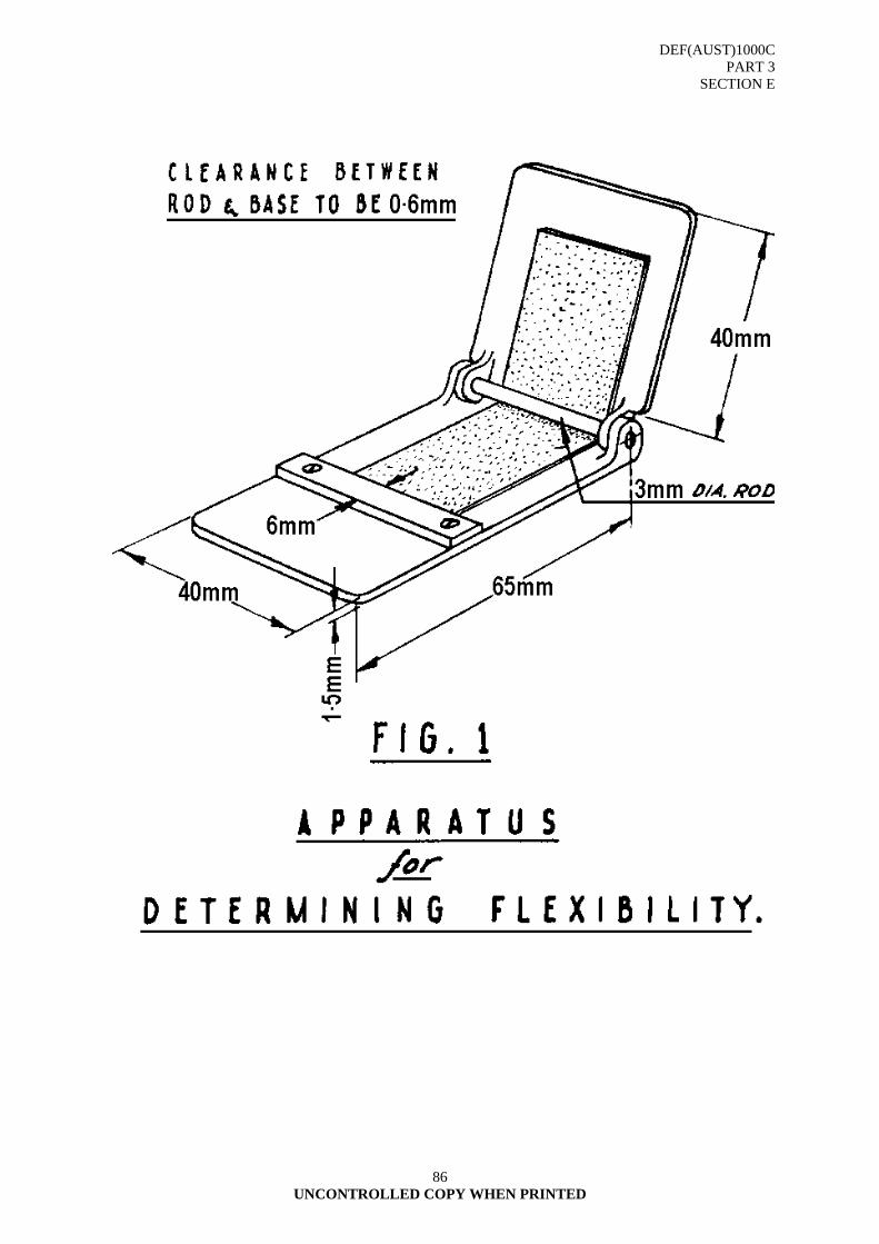
DEF(AUST)1000C PART 3
SECTION E
UNCONTROLLED COPY WHEN PRINTED
86
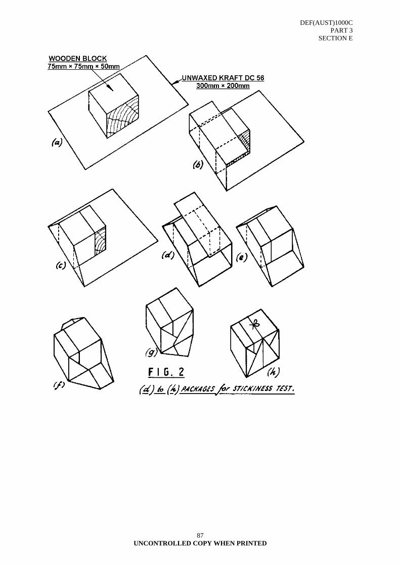
DEF(AUST)1000C PART 3
SECTION E
UNCONTROLLED COPY WHEN PRINTED
87
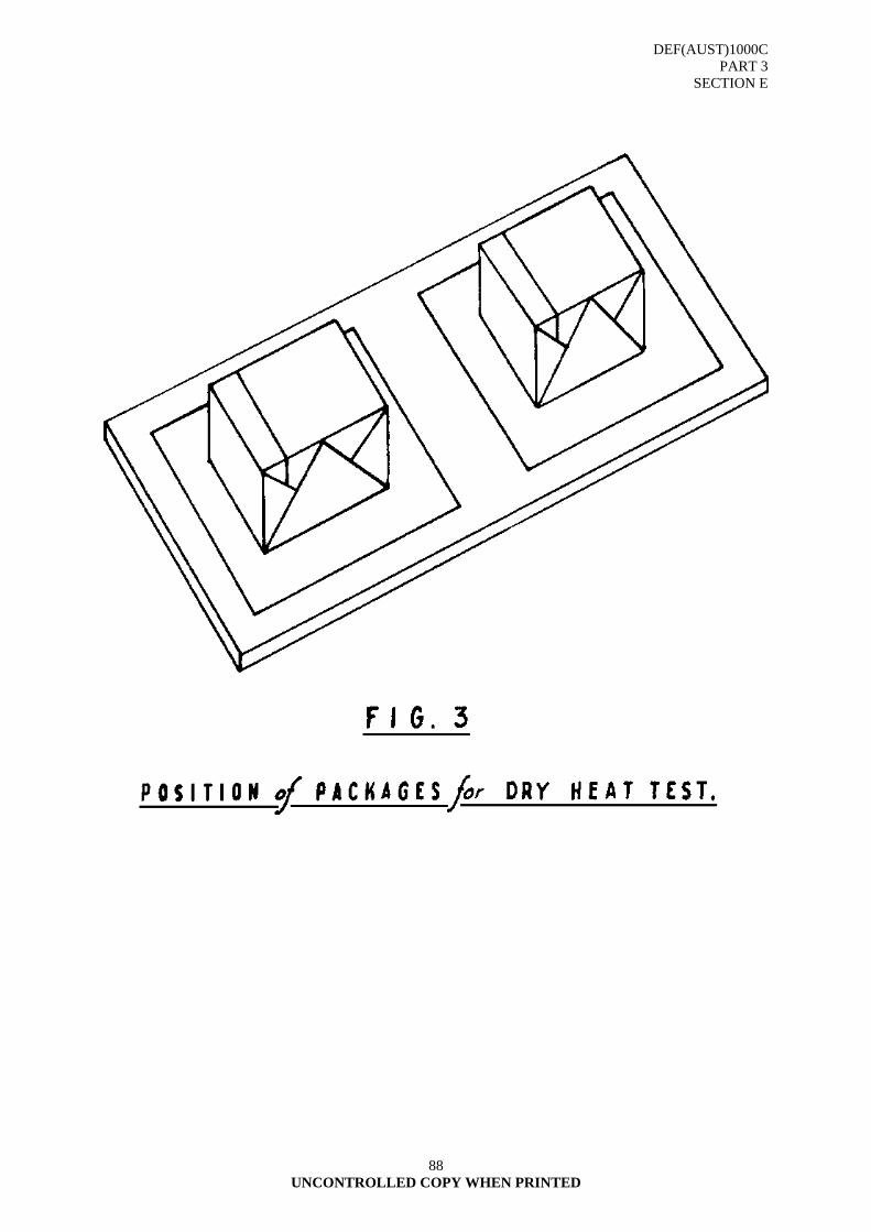
DEF(AUST)1000C PART 3
SECTION E
UNCONTROLLED COPY WHEN PRINTED
88
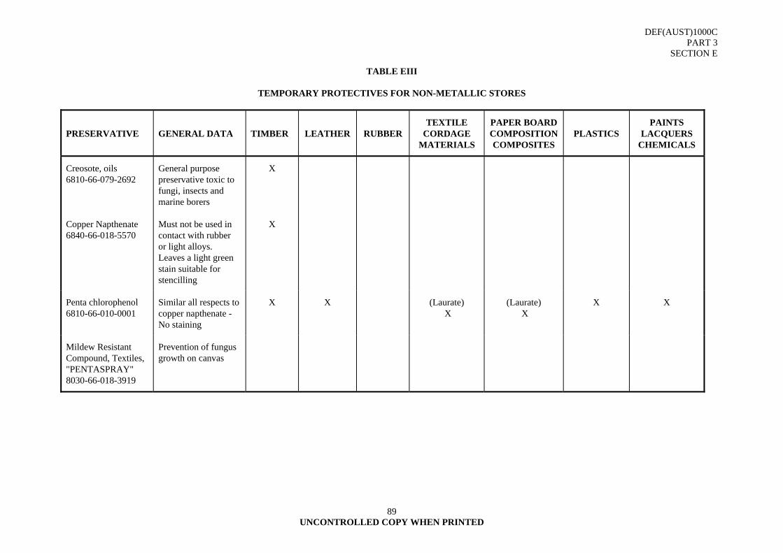
DEF(AUST)1000C PART 3
SECTION E
UNCONTROLLED COPY WHEN PRINTED
89
TABLE EIII
TEMPORARY PROTECTIVES FOR NON-METALLIC STORES
PRESERVATIVE GENERAL DATA TIMBER LEATHER RUBBER TEXTILE
CORDAGE MATERIALS
PAPER BOARD COMPOSITIONCOMPOSITES
PLASTICS PAINTS
LACQUERS CHEMICALS
Creosote, oils 6810-66-079-2692
General purpose preservative toxic to fungi, insects and marine borers
X
Copper Napthenate 6840-66-018-5570
Must not be used in contact with rubber or light alloys. Leaves a light green stain suitable for stencilling
X
Penta chlorophenol 6810-66-010-0001
Similar all respects to copper napthenate - No staining
X X (Laurate) X
(Laurate) X
X X
Mildew Resistant Compound, Textiles, "PENTASPRAY" 8030-66-018-3919
Prevention of fungus growth on canvas
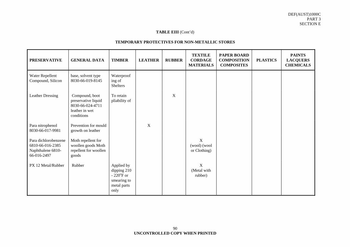
DEF(AUST)1000C PART 3
SECTION E
UNCONTROLLED COPY WHEN PRINTED
90
TABLE EIII (Cont’d)
TEMPORARY PROTECTIVES FOR NON-METALLIC STORES
PRESERVATIVE GENERAL DATA TIMBER LEATHER RUBBER TEXTILE
CORDAGE MATERIALS
PAPER BOARD COMPOSITIONCOMPOSITES
PLASTICS PAINTS
LACQUERS CHEMICALS
Water Repellent Compound, Silicon
base, solvent type 8030-66-019-8145
Waterproof ing of Shelters
Leather Dressing Compound, boot preservative liquid 8030-66-024-4711 leather in wet conditions
To retain pliability of
X
Para nitrophenol 8030-66-017-9981
Prevention for mould growth on leather
X
Para dichlorobenzene 6810-66-016-2385 Naphthalene 6810-66-016-2497
Moth repellent for woollen goods Moth repellent for woollen goods
X (wool) (wool or Clothing)
PX 12 Metal/Rubber Rubber Applied by dipping 210 - 220oF or smearing to metal parts only
X (Metal with
rubber)
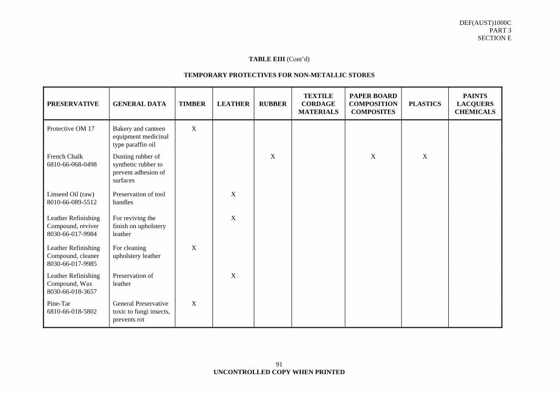
DEF(AUST)1000C PART 3
SECTION E
UNCONTROLLED COPY WHEN PRINTED
91
TABLE EIII (Cont’d)
TEMPORARY PROTECTIVES FOR NON-METALLIC STORES
PRESERVATIVE GENERAL DATA TIMBER LEATHER RUBBER TEXTILE
CORDAGE MATERIALS
PAPER BOARD COMPOSITIONCOMPOSITES
PLASTICS PAINTS
LACQUERS CHEMICALS
Protective OM 17 Bakery and canteen equipment medicinal type paraffin oil
X
French Chalk 6810-66-068-0498
Dusting rubber of synthetic rubber to prevent adhesion of surfaces
X X X
Linseed Oil (raw) 8010-66-089-5512
Preservation of tool handles
X
Leather Refinishing Compound, reviver 8030-66-017-9984
For reviving the finish on upholstery leather
X
Leather Refinishing Compound, cleaner 8030-66-017-9985
For cleaning upholstery leather
X
Leather Refinishing Compound, Wax 8030-66-018-3657
Preservation of leather
X
Pine-Tar 6810-66-018-5802
General Preservative toxic to fungi insects, prevents rot
X
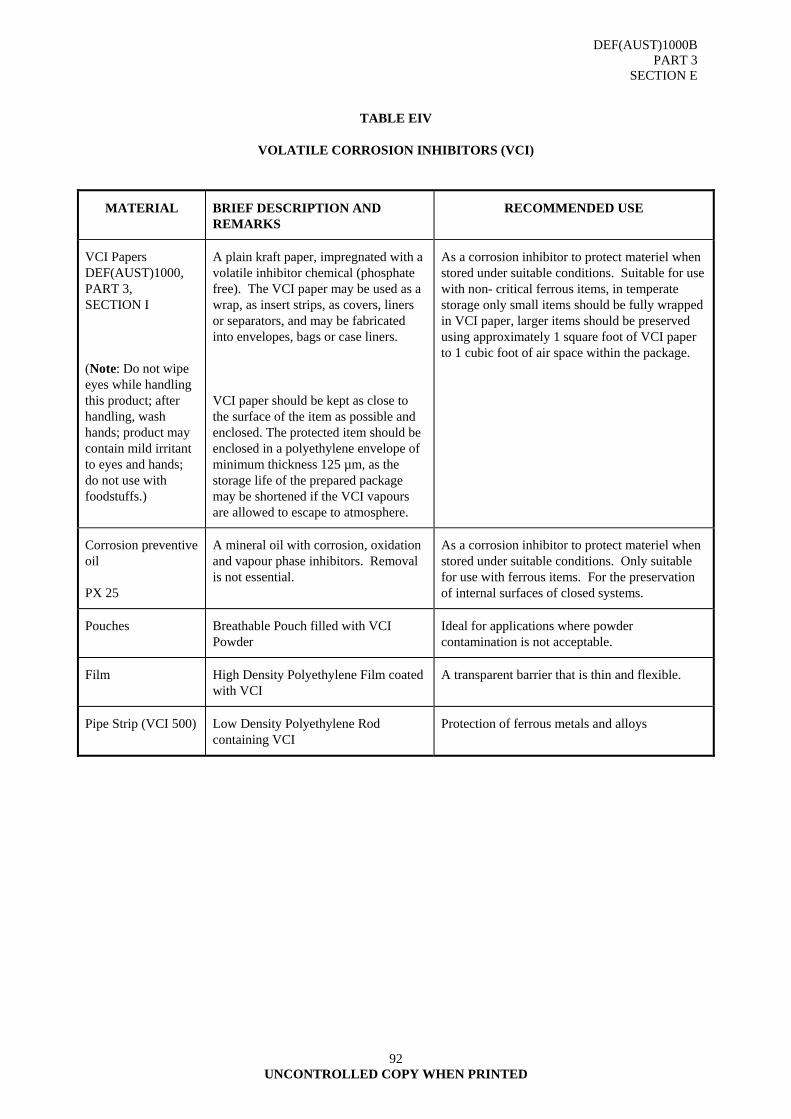
DEF(AUST)1000B PART 3
SECTION E
UNCONTROLLED COPY WHEN PRINTED
92
TABLE EIV
VOLATILE CORROSION INHIBITORS (VCI)
MATERIAL BRIEF DESCRIPTION AND REMARKS
RECOMMENDED USE
VCI Papers DEF(AUST)1000, PART 3, SECTION I
(Note: Do not wipe eyes while handling this product; after handling, wash hands; product may contain mild irritant to eyes and hands; do not use with foodstuffs.)
A plain kraft paper, impregnated with a volatile inhibitor chemical (phosphate free). The VCI paper may be used as a wrap, as insert strips, as covers, liners or separators, and may be fabricated into envelopes, bags or case liners.
VCI paper should be kept as close to the surface of the item as possible and enclosed. The protected item should be enclosed in a polyethylene envelope of minimum thickness 125 µm, as the storage life of the prepared package may be shortened if the VCI vapours are allowed to escape to atmosphere.
As a corrosion inhibitor to protect materiel when stored under suitable conditions. Suitable for use with non- critical ferrous items, in temperate storage only small items should be fully wrapped in VCI paper, larger items should be preserved using approximately 1 square foot of VCI paper to 1 cubic foot of air space within the package.
Corrosion preventive oil
PX 25
A mineral oil with corrosion, oxidation and vapour phase inhibitors. Removal is not essential.
As a corrosion inhibitor to protect materiel when stored under suitable conditions. Only suitable for use with ferrous items. For the preservation of internal surfaces of closed systems.
Pouches Breathable Pouch filled with VCI Powder
Ideal for applications where powder contamination is not acceptable.
Film High Density Polyethylene Film coated with VCI
A transparent barrier that is thin and flexible.
Pipe Strip (VCI 500) Low Density Polyethylene Rod containing VCI
Protection of ferrous metals and alloys
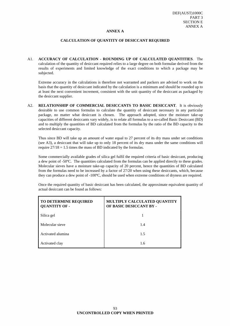
DEF(AUST)1000C PART 3
SECTION E ANNEX A
UNCONTROLLED COPY WHEN PRINTED
93
ANNEX A
CALCULATION OF QUANTITY OF DESICCANT REQUIRED
A1. ACCURACY OF CALCULATION - ROUNDING UP OF CALCULATED QUANTITIES. The
calculation of the quantity of desiccant required relies to a large degree on both formulae derived from the results of experiments and limited knowledge of the exact conditions to which a package may be subjected.
Extreme accuracy in the calculations is therefore not warranted and packers are advised to work on the
basis that the quantity of desiccant indicated by the calculation is a minimum and should be rounded up to at least the next convenient increment, consistent with the unit quantity of the desiccant as packaged by the desiccant supplier.
A2. RELATIONSHIP OF COMMERCIAL DESICCANTS TO BASIC DESICCANT. It is obviously
desirable to use common formulas to calculate the quantity of desiccant necessary in any particular package, no matter what desiccant is chosen. The approach adopted, since the moisture take-up capacities of different desiccants vary widely, is to relate all formulas to a so-called Basic Desiccant (BD) and to multiply the quantities of BD calculated from the formulas by the ratio of the BD capacity to the selected desiccant capacity.
Thus since BD will take up an amount of water equal to 27 percent of its dry mass under set conditions
(see A3), a desiccant that will take up to only 18 percent of its dry mass under the same conditions will require 27/18 = 1.5 times the mass of BD indicated by the formulas.
Some commercially available grades of silica gel fulfil the required criteria of basic desiccant, producing
a dew point of -50ºC. The quantities calculated from the formulas can be applied directly to these grades. Molecular sieves have a moisture take-up capacity of 20 percent, hence the quantities of BD calculated from the formulas need to be increased by a factor of 27/20 when using these desiccants, which, because they can produce a dew point of -100ºC, should be used when extreme conditions of dryness are required.
Once the required quantity of basic desiccant has been calculated, the approximate equivalent quantity of
actual desiccant can be found as follows:
TO DETERMINE REQUIRED QUANTITY OF -
MULTIPLY CALCULATED QUANTITY OF BASIC DESICCANT BY -
Silica gel 1
Molecular sieve 1.4
Activated alumina 1.5
Activated clay 1.6
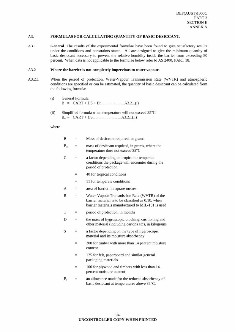
DEF(AUST)1000C PART 3
SECTION E ANNEX A
UNCONTROLLED COPY WHEN PRINTED
94
A3. FORMULAS FOR CALCULATING QUANTITY OF BASIC DESICCANT. A3.1 General. The results of the experimental formulae have been found to give satisfactory results
under the conditions and constraints stated. All are designed to give the minimum quantity of basic desiccant necessary to prevent the relative humidity inside the barrier from exceeding 50 percent. When data is not applicable to the formulae below refer to AS 2400, PART 18.
A3.2 Where the barrier is not completely impervious to water vapour. A3.2.1 When the period of protection, Water-Vapour Transmission Rate (WVTR) and atmospheric
conditions are specified or can be estimated, the quantity of basic desiccant can be calculated from the following formula:
(i) General Formula B = CART + DS + Bt........................A3.2.1(i) (ii) Simplified formula when temperature will not exceed 35°C Bo = CART + DS.............................A3.2.1(ii) where
B = Mass of desiccant required, in grams
Bo = mass of desiccant required, in grams, where the temperature does not exceed 35°C
C = a factor depending on tropical or temperate conditions the package will encounter during the period of protection
= 40 for tropical conditions
= 11 for temperate conditions
A = area of barrier, in square metres
R = Water-Vapour Transmission Rate (WVTR) of the barrier material is to be classified as 0.10, when barrier materials manufactured to MIL-131 is used
T = period of protection, in months
D = the mass of hygroscopic blocking, cushioning and other material (including cartons etc), in kilograms
S = a factor depending on the type of hygroscopic material and its moisture absorbency
= 200 for timber with more than 14 percent moisture content
= 125 for felt, paperboard and similar general packaging materials
= 100 for plywood and timbers with less than 14 percent moisture content
Bt = an allowance made for the reduced absorbency of basic desiccant at temperatures above 35°C.

DEF(AUST)1000C PART 3
SECTION E ANNEX A
UNCONTROLLED COPY WHEN PRINTED
95
Allowance Bt Basic desiccant suffers a 2 percent reduction in absorbency for each degree Celsius above 35°C. Therefore - (iii) where the temperature during the period of protection will not exceed 35°C; Bt = 0 and the minimum quantity of basic desiccant required becomes; B = Bo = CART + DS (iv) where temperatures are likely to exceed 35°C; Bt = 0.02(t - 35) Bo where t is the maximum expected temperature, in degrees Celsius and Bo = CART + DS therefore- B = (CART + DS)(1 + 0.02(t-35)) It should be noted that the temperature allowance is correct for basic desiccant, e.g. silica gel; it
provides an approximation only to a temperature correction for activated alumina and activated clay, and no correction for temperature is necessary for molecular sieves below 70°C.
If other than silica gel is to used, therefore, the Bt correction should be discarded before
applying the factors shown in paragraph A2. A3.3 Where the barrier is completely impervious to water-vapour. When the barrier is completely
impervious to water-vapour, e.g. in a well-soldered metal container, the formula to be used is as follows:
B = 160 V + DS..................................A3.3 where symbols and factors have the same meaning and values as in Paragraph A3.2, and V = volume
inside the barrier (neglecting the volume of the item packed), in cubic metres. Example. If in the example quoted in paragraph A3.2.1 a well-soldered metal box is to be used instead of
polyethylene film for the barrier, using the same details as applicable in that example- V = 1.22 x 1.68 x 0.91 m3 = 1.87 m³ For timber component - D = 6.12 kg S = 200 For felt component - D = 0.68 kg S = 125 And the quantity of basic desiccant necessary is as follows: B = (160 x 1.87) + (6.12 x 200) + (0.68 x 125) g = 300 + 1224 + 85 g = 1609 g Say 2 kg.
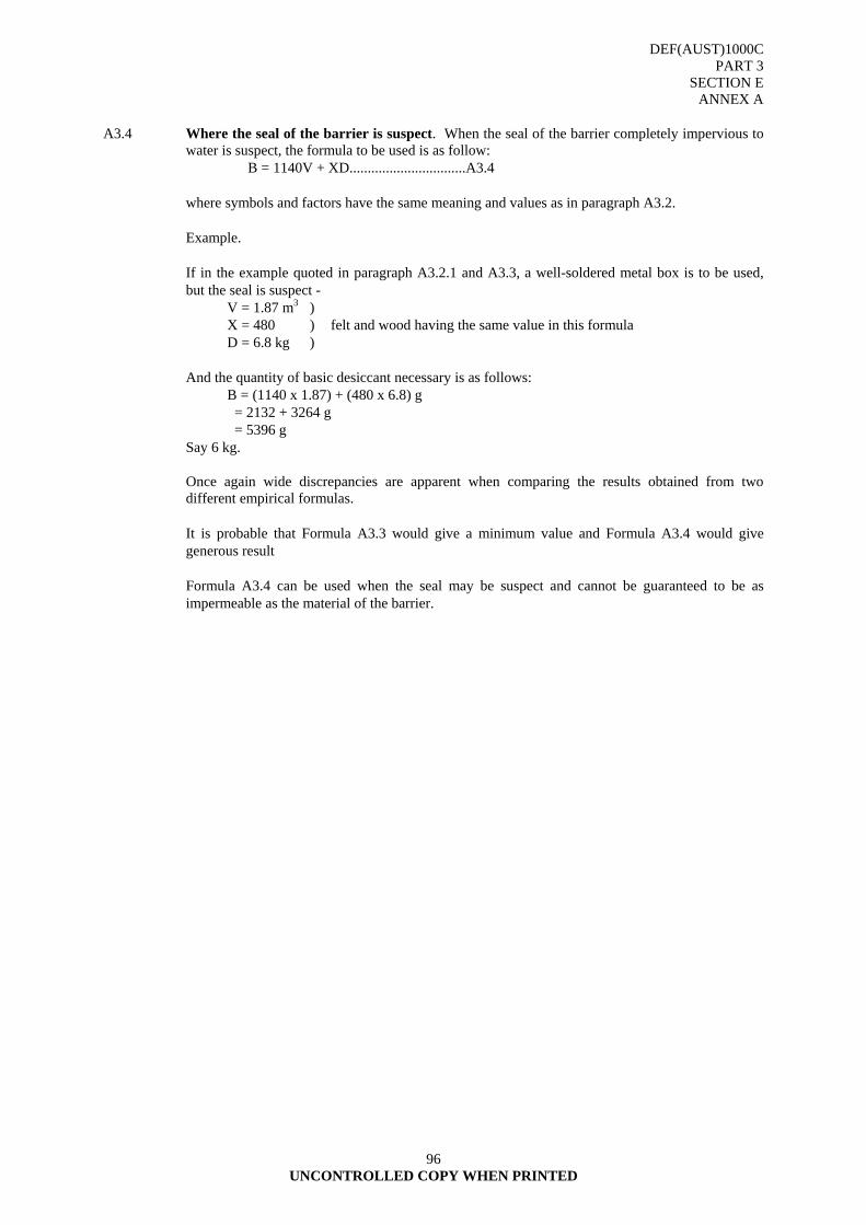
DEF(AUST)1000C PART 3
SECTION E ANNEX A
UNCONTROLLED COPY WHEN PRINTED
96
A3.4 Where the seal of the barrier is suspect. When the seal of the barrier completely impervious to
water is suspect, the formula to be used is as follow: B = 1140V + XD................................A3.4 where symbols and factors have the same meaning and values as in paragraph A3.2. Example. If in the example quoted in paragraph A3.2.1 and A3.3, a well-soldered metal box is to be used,
but the seal is suspect - V = 1.87 m3 ) X = 480 ) felt and wood having the same value in this formula D = 6.8 kg ) And the quantity of basic desiccant necessary is as follows: B = (1140 x 1.87) + (480 x 6.8) g = 2132 + 3264 g = 5396 g Say 6 kg. Once again wide discrepancies are apparent when comparing the results obtained from two
different empirical formulas. It is probable that Formula A3.3 would give a minimum value and Formula A3.4 would give
generous result Formula A3.4 can be used when the seal may be suspect and cannot be guaranteed to be as
impermeable as the material of the barrier.

DEF(AUST)1000C PART 3
SECTION E ANNEX B
UNCONTROLLED COPY WHEN PRINTED 97
ANNEX B
USE OF HUMIDITY INDICATORS
B1. It is an occasional requirement that the relative humidity in the package should be checked during
storage to ascertain that the critical level of 50 per cent has not been exceeded. With commonly used silica gel, the colour change accompanying its saturation, blue to pink, is the best indicator. When this desiccant is seen to be pink, it should be replaced. Another simple method is the use of absorbent paper soaked in cobalt chloride and dried. This paper again is blue when dry but changes to pink on exposure to a relative humidity in excess of 50 per cent (Refer FIGURE 1).
B1.1 Indicators must be positioned as far as possible away from the desiccant so that accurate information
on the internal humidity of the package is given. If the barrier material is not transparent, a window should be provided so that the indicator may be observed without opening the package.
B1.2 In Method II Packaging, the practical life of the element used to indicate humidity becomes extremely
important. A method is required for sealing within the package a sensitive device capable of providing an indication of humidity inside the package over a relatively long period of time. One method is the electrical humidity indicating system. Briefly, the system consists of an electrical sensing element assembly (composed of a sensing element, a barrier seal and an electrical conductor) which is incorporated as an integral part of the Method II package at the time of fabrication. The electrical conductor extends from within the packaging through the vapourproof barrier to the outside of the exterior container. By use of a portable indicating instrument, determination of the moisture level can be made by contact with the terminals on the container.
B1.3 The atmosphere of storage facilities using dynamic dehumidification should be continuously checked
to ensure the maintenance of proper storage conditions. This can be accomplished by a monitor and recorder system linked to sensor devices. In this system, two pens mark a spring or electrically driven chart. One sensor element drives one pen to record humidity while a second sensor drives the other pen to record temperature. The system provides a continuous record of humidity and temperature during the storage term. Humidity sensing and driving devices may be of the capacitive type, hygroscopic film type or hygroscopic hair type. Temperature sensing devices are usually bi-metal strips or thermistors (temperature sensitive resistors). These same types of sensors can also be used to actuate humidistats or thermostats to operate the humidity and temperature control equipment. Indicator and control system sensors should be checked periodically for accuracy by comparing their readings with those of laboratory grade hygrometers. The dry and wet-bulb temperatures obtained from the hygrometer are interpreted on a psychrometric chart to obtain the true relative humidity value.
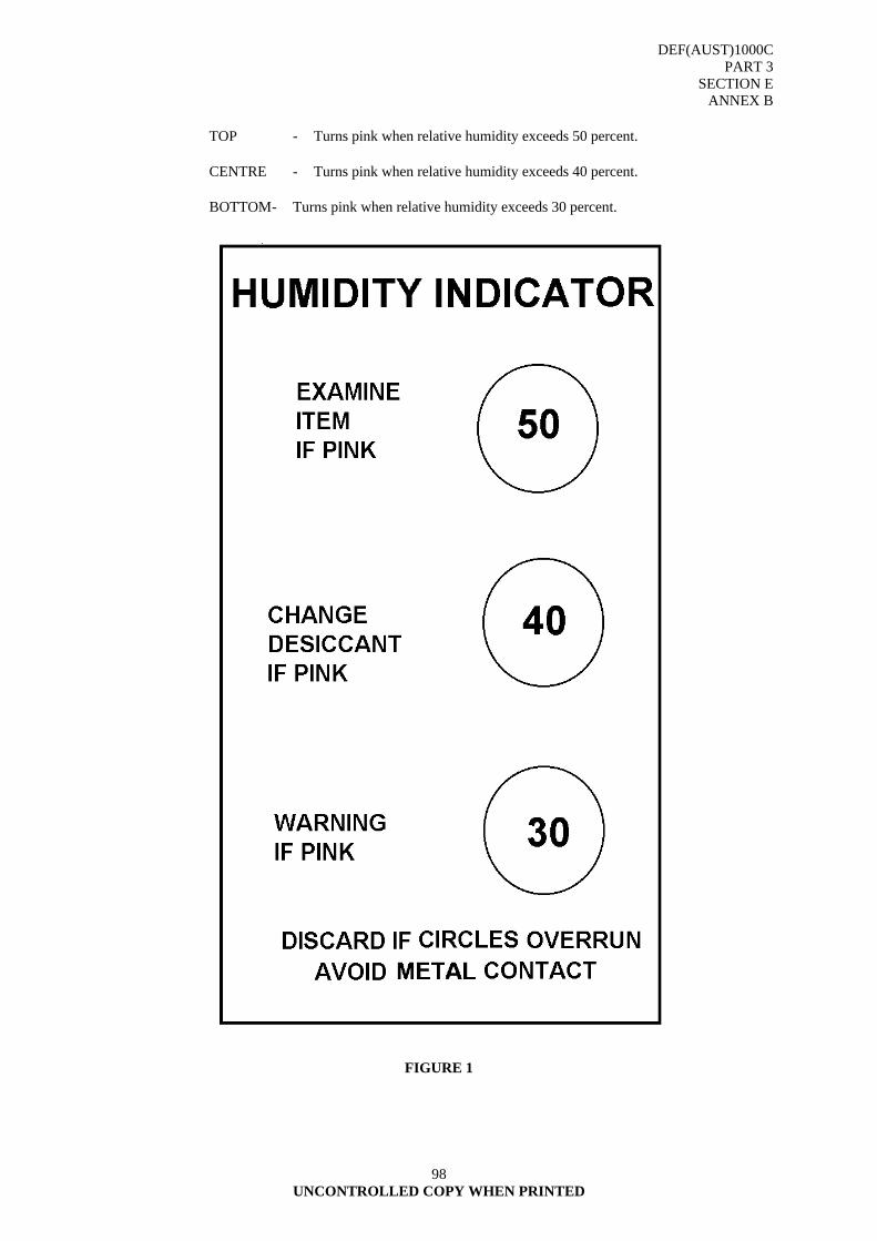
DEF(AUST)1000C PART 3
SECTION E ANNEX B
UNCONTROLLED COPY WHEN PRINTED
98
TOP - Turns pink when relative humidity exceeds 50 percent. CENTRE - Turns pink when relative humidity exceeds 40 percent. BOTTOM - Turns pink when relative humidity exceeds 30 percent.
FIGURE 1
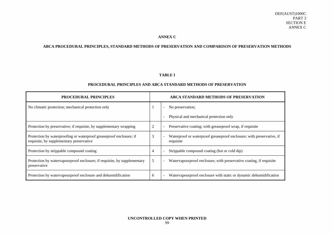
DEF(AUST)1000C PART 3
SECTION E ANNEX C
UNCONTROLLED COPY WHEN PRINTED 99
ANNEX C
ABCA PROCEDURAL PRINCIPLES, STANDARD METHODS OF PRESERVATION AND COMPARISON OF PRESERVATION METHODS
TABLE I
PROCEDURAL PRINCIPLES AND ABCA STANDARD METHODS OF PRESERVATION
PROCEDURAL PRINCIPLES ABCA STANDARD METHODS OF PRESERVATION
No climatic protection; mechanical protection only 1 - No preservation;
- Physical and mechanical protection only
Protection by preservative; if requisite, by supplementary wrapping 2 - Preservative coating; with greaseproof wrap, if requisite
Protection by waterproofing or waterproof greaseproof enclosure; if requisite, by supplementary preservative
3 - Waterproof or waterproof greaseproof enclosure; with preservative, if requisite
Protection by strippable compound coating 4 - Strippable compound coating (hot or cold dip)
Protection by watervapourproof enclosure; if requisite, by supplementary preservative
5 - Watervapourproof enclosure; with preservative coating, if requisite
Protection by watervapourproof enclosure and dehumidification 6 - Watervapourproof enclosure with static or dynamic dehumidification
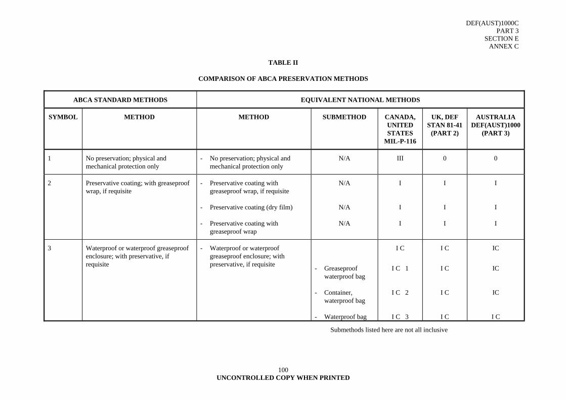
DEF(AUST)1000C PART 3
SECTION E ANNEX C
UNCONTROLLED COPY WHEN PRINTED
100
TABLE II
COMPARISON OF ABCA PRESERVATION METHODS
ABCA STANDARD METHODS EQUIVALENT NATIONAL METHODS
SYMBOL METHOD METHOD SUBMETHOD CANADA, UNITED STATES
MIL-P-116
UK, DEF STAN 81-41
(PART 2)
AUSTRALIA DEF(AUST)1000
(PART 3)
1 No preservation; physical and mechanical protection only
- No preservation; physical and mechanical protection only
N/A III 0 0
2 Preservative coating; with greaseproof wrap, if requisite
- Preservative coating with greaseproof wrap, if requisite
- Preservative coating (dry film)
- Preservative coating with greaseproof wrap
N/A
N/A
N/A
I
I
I
I
I
I
I
I
I
3 Waterproof or waterproof greaseproof enclosure; with preservative, if requisite
- Waterproof or waterproof greaseproof enclosure; with preservative, if requisite
- Greaseproof waterproof bag
- Container, waterproof bag
- Waterproof bag
I C
I C 1
I C 2
I C 3
I C
I C
I C
I C
IC
IC
IC
I C
Submethods listed here are not all inclusive
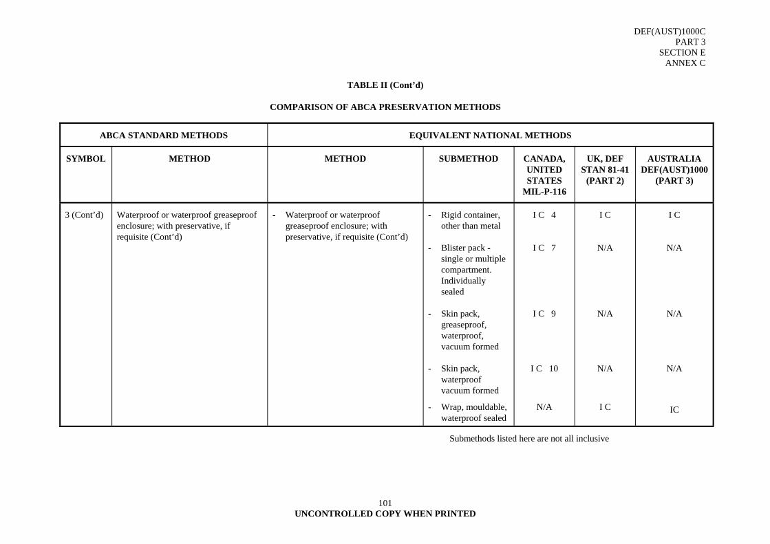
DEF(AUST)1000C PART 3
SECTION E ANNEX C
UNCONTROLLED COPY WHEN PRINTED
101
TABLE II (Cont’d)
COMPARISON OF ABCA PRESERVATION METHODS
ABCA STANDARD METHODS EQUIVALENT NATIONAL METHODS
SYMBOL METHOD METHOD SUBMETHOD CANADA, UNITED STATES
MIL-P-116
UK, DEF STAN 81-41
(PART 2)
AUSTRALIA DEF(AUST)1000
(PART 3)
3 (Cont’d) Waterproof or waterproof greaseproof enclosure; with preservative, if requisite (Cont’d)
- Waterproof or waterproof greaseproof enclosure; with preservative, if requisite (Cont’d)
- Rigid container, other than metal
- Blister pack - single or multiple compartment. Individually sealed
- Skin pack, greaseproof, waterproof, vacuum formed
- Skin pack, waterproof vacuum formed
- Wrap, mouldable, waterproof sealed
I C 4
I C 7
I C 9
I C 10
N/A
I C
N/A
N/A
N/A
I C
I C
N/A
N/A
N/A
IC
Submethods listed here are not all inclusive
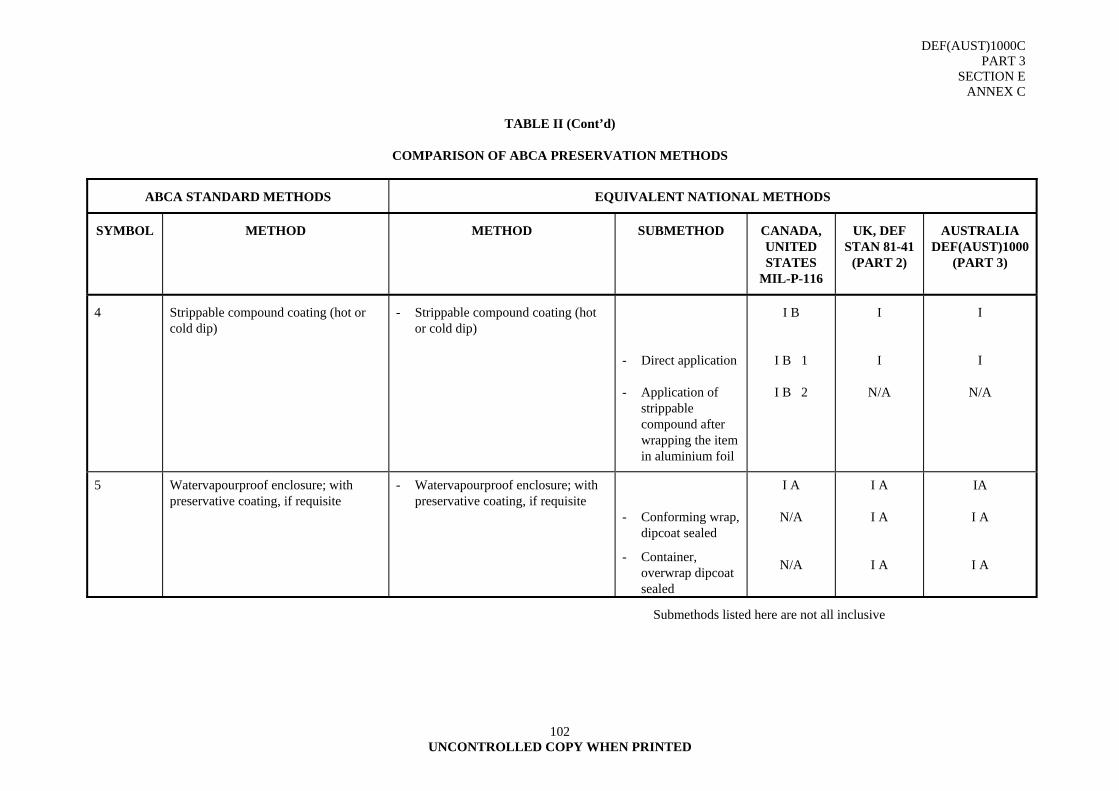
DEF(AUST)1000C PART 3
SECTION E ANNEX C
UNCONTROLLED COPY WHEN PRINTED
102
TABLE II (Cont’d)
COMPARISON OF ABCA PRESERVATION METHODS
ABCA STANDARD METHODS EQUIVALENT NATIONAL METHODS
SYMBOL METHOD METHOD SUBMETHOD CANADA, UNITED STATES
MIL-P-116
UK, DEF STAN 81-41
(PART 2)
AUSTRALIA DEF(AUST)1000
(PART 3)
4 Strippable compound coating (hot or cold dip)
- Strippable compound coating (hot or cold dip)
- Direct application
- Application of strippable compound after wrapping the item in aluminium foil
I B
I B 1
I B 2
I
I
N/A
I
I
N/A
5 Watervapourproof enclosure; with preservative coating, if requisite
- Watervapourproof enclosure; with preservative coating, if requisite
- Conforming wrap,
dipcoat sealed
- Container, overwrap dipcoat sealed
I A
N/A
N/A
I A
I A
I A
IA
I A
I A
Submethods listed here are not all inclusive
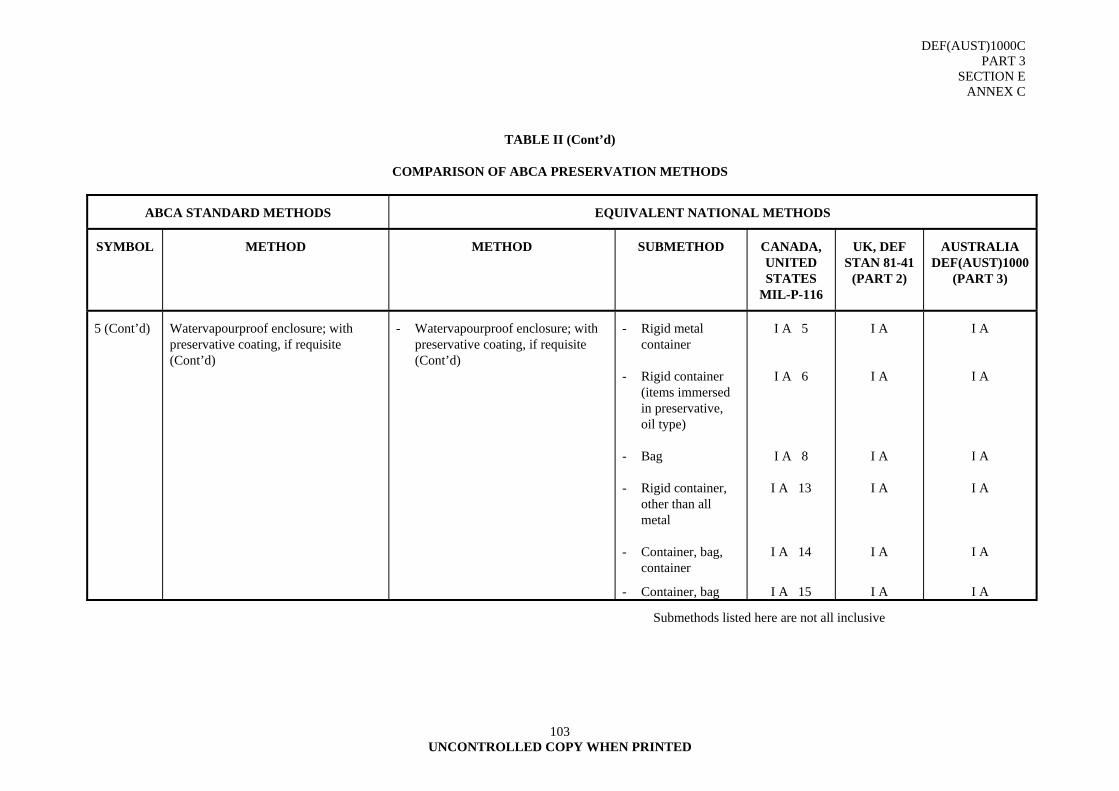
DEF(AUST)1000C PART 3
SECTION E ANNEX C
UNCONTROLLED COPY WHEN PRINTED
103
TABLE II (Cont’d)
COMPARISON OF ABCA PRESERVATION METHODS
ABCA STANDARD METHODS EQUIVALENT NATIONAL METHODS
SYMBOL METHOD METHOD SUBMETHOD CANADA, UNITED STATES
MIL-P-116
UK, DEF STAN 81-41
(PART 2)
AUSTRALIA DEF(AUST)1000
(PART 3)
5 (Cont’d) Watervapourproof enclosure; with preservative coating, if requisite (Cont’d)
- Watervapourproof enclosure; with preservative coating, if requisite (Cont’d)
- Rigid metal container
- Rigid container (items immersed in preservative, oil type)
- Bag
- Rigid container, other than all metal
- Container, bag, container
- Container, bag
I A 5
I A 6
I A 8
I A 13
I A 14
I A 15
I A
I A
I A
I A
I A
I A
I A
I A
I A
I A
I A
I A
Submethods listed here are not all inclusive
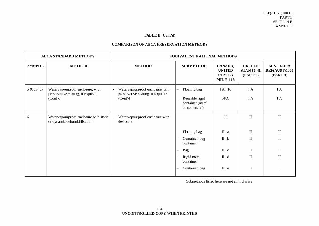
DEF(AUST)1000C PART 3
SECTION E ANNEX C
UNCONTROLLED COPY WHEN PRINTED
104
TABLE II (Cont’d)
COMPARISON OF ABCA PRESERVATION METHODS
ABCA STANDARD METHODS EQUIVALENT NATIONAL METHODS
SYMBOL METHOD METHOD SUBMETHOD CANADA, UNITED STATES
MIL-P-116
UK, DEF STAN 81-41
(PART 2)
AUSTRALIA DEF(AUST)1000
(PART 3)
5 (Cont’d) Watervapourproof enclosure; with preservative coating, if requisite (Cont’d)
- Watervapourproof enclosure; with preservative coating, if requisite (Cont’d)
- Floating bag
- Reusable rigid container (metal or non-metal)
I A 16
N/A
I A
I A
I A
I A
6 Watervapourproof enclosure with static or dynamic dehumidification
- Watervapourproof enclosure with desiccant
- Floating bag
- Container, bag container
- Bag
- Rigid metal container
- Container, bag
II
II a
II b
II c
II d
II e
II
II
II
II
II
II
II
II
II
II
II
II
Submethods listed here are not all inclusive
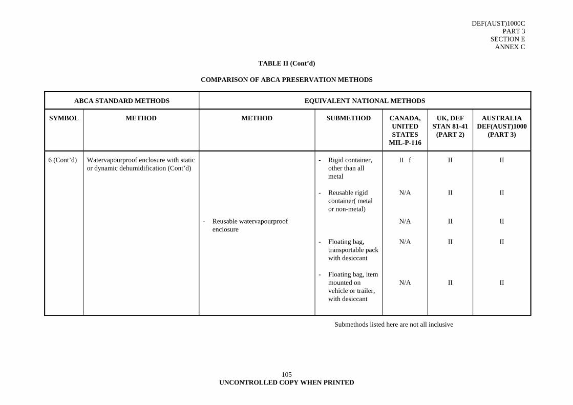
DEF(AUST)1000C PART 3
SECTION E ANNEX C
UNCONTROLLED COPY WHEN PRINTED
105
TABLE II (Cont’d)
COMPARISON OF ABCA PRESERVATION METHODS
ABCA STANDARD METHODS EQUIVALENT NATIONAL METHODS
SYMBOL METHOD METHOD SUBMETHOD CANADA, UNITED STATES
MIL-P-116
UK, DEF STAN 81-41
(PART 2)
AUSTRALIA DEF(AUST)1000
(PART 3)
6 (Cont’d) Watervapourproof enclosure with static or dynamic dehumidification (Cont’d)
- Reusable watervapourproof enclosure
- Rigid container, other than all metal
- Reusable rigid container( metal or non-metal)
- Floating bag, transportable pack with desiccant
- Floating bag, item mounted on vehicle or trailer, with desiccant
II f
N/A
N/A
N/A
N/A
II
II
II
II
II
II
II
II
II
II
Submethods listed here are not all inclusive
DEF(AUST)1000C PART 3
SECTION F
UNCONTROLLED COPY WHEN PRINTED 106
SECTION F - BARRIER MATERIAL - BUNDLING - BALING - WRAPPING - BLOCKING –
BRACING 1. INTRODUCTION
1.1 A barrier material is a paper, film, foil, fabric or composite material designed to resist the penetration of water, water vapour, grease or certain gases (refer DEF(AUST)1000, PART 3, SECTION L, Guide of Common Barrier Wraps). It provides a physical shield against the ingress or egress of elements, which cause loss, or deterioration of the contents of a package.
2. HANDLING AND STORAGE
2.1 The correct handling and storage of barrier materials is necessary to avoid inefficient packaging operations and wastage of materials. Rolls should be stored on end, and sheets on their flat surfaces. The ideal storage temperature is within the range 7º - 24ºC, and a relative humidity of 40 - 50 percent. The use of a dispenser unit will contribute greatly to economy of rolls of barrier materials and prevent wastage.
3. SELECTING A BARRIER MATERIAL
3.1 Before selecting a barrier material, the characteristics of the item being packed, and the characteristics of the barrier material itself must be considered. For example:
a. the barrier material and the packaged item must be compatible to protect them against deterioration, and to prevent harmful interaction between the item and the barrier material,
b. the major dimensions of the item must be known to determine the amount of barrier material, the type, (e.g., roll, sheet, bag or envelope form) and size,
c. the barrier material must be compatible with all other packaging materials it may come in contact with, including preservatives and the outer wrap, to prevent the harmful interaction that may affect the integrity of the package, and
d. the availability of the barrier material must be known. If special equipment is required for applying the barrier material, it must be available, and be suitable for use with the item.
4. COMPOSITE BARRIER MATERIALS
4.1 Composite barrier materials have been designed to ensure long term storage under all climatic conditions. They are constructed to keep preservative oils and greases in contact with metal surfaces, and to keep water and water vapour out of the interior of packages.
4.2 Regardless of how good the barrier material may be, if the package is not adequately closed and sealed, the contents may arrive at their destination in an unserviceable condition. Therefore, all closures and seals must be leakproof and must give the same degree of protection as the barrier material itself, against water, water vapour and gas.
4.3 There are three major types of heat sealable barrier materials based on the degree of protection afforded by the material. They are:
a. a waterproofed flexible material which has a high degree of resistance to the penetration of water,
b. a flexible material having low water vapour transmission characteristics, and
c. flexible thermoplastic films.
DEF(AUST)1000C PART 3
SECTION F
UNCONTROLLED COPY WHEN PRINTED
107
5. WATERPROOFED FLEXIBLE BARRIER MATERIAL
5.1 This material is constructed of one or more plies of kraft paper, laminated with bitumen or plastic adhesive and reinforced by sisal fibres or multi/mono filaments. When heat-sealing characteristics are required, one outer ply is coated with a polyethylene film.
5.2 Waterproofed barrier materials are used to wrap individual packages, manufacture box liners, bale, bandage wrap, line open crates and provide temporary storage covers.
6. WATER VAPOURPROOFED FLEXIBLE BARRIER MATERIALS
6.1 This material is constructed from kraft paper, aluminium foil, scrim (fabric) and polyethylene or any combination of these materials. The material has high tensile strength and is not usually reinforced with fibres or filaments for additional strength. It has low water vapour transmission properties and is used where the highest degree of protection from damage caused by the effects of water is required. It is used for the manufacture of bags, pouches and envelopes, and overwrapping primary containers where mechanical or electrical items with functional components which cannot be treated with a preservative still require the utmost protection. Any enclosed air must be exhausted and heat sealing temperature, dwell time and pressure adjusted to the manufacturer's recommendation. Most normal heat sealing machines will not seal this material efficiently.
7. FLEXIBLE THERMOPLASTIC FILMS
7.1 This material is an unsupported, transparent flexible film manufactured from polyethylene or other fluorocarbons, and may be a composite plastic material. It is used as a wrapper, or in the manufacture of bags, envelopes, box liners, and for a wide range of other uses as it provides a water resistant barrier for the protection of Service items and equipment.
8. HEAT SEALABLE BARRIER MATERIALS
8.1 To understand the factors essential to proper heat sealing, and the equipment needed to produce an acceptable seal, a general knowledge of the construction of the materials involved is helpful.
8.2 Most of the heat sealable barrier materials are composed of several layers or plies of unlike materials laminated together to form a multi-ply or built up sheet. The structure of such a sheet is a heat sealable face, an impervious ply and a backing ply. The heat sealable face may be a thermoplastic film or coating which has the ability to become semi-fluid and flow upon the application of heat. After cooling, the plastic returns to a normal solid, flexible state. This facing material is usually polyethylene, vinyl chloride or other plastic film. In addition to providing a heat sealable face, the plastic ply serves to fill the tiny pin holes in the underlying plies to make the barrier water, grease or vapour resistant.
8.3 The impervious ply is composed of aluminium foil or polyethylene/cellulose-acetate film which gives the whole barrier its greaseproof, waterproof or vapourproof properties.
8.4 The backing ply is usually a scrim (cotton cloth), other fabric or kraft paper. The purpose of the ply is to increase resistance to abrasion, wear and puncture, and to improve the tensile strength of the whole sheet.
9. STATIC CONDUCTIVITY IN PLASTIC FILMS
9.1 Unpleasant and sometimes dangerous electrostatic charges can build up on flexible plastic barrier films. These charges are generated by friction from the film rubbing either against itself, or against other non-metallic materials. This may occur during packaging or later.
9.2 Static charges on large sheets of film can result in dangerous sparking, the attraction and holding of dust or other undesirable particles, or merely nuisances such as unpleasant shocks and difficulty in handling the film because of clinging. This electrical discharge therefore should be a prime factor when considering barrier materials in packaging highly flammable materials and Electro Static Sensitive Devices (ESSD) where susceptibility to sparking, foreign particles and electrostatic discharge is a factor. Generally, a non-plastic barrier material should be used in these cases. ESSD should always be packaged in accordance with DI(AF) AAP 3533.021.
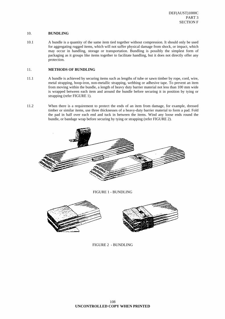
DEF(AUST)1000C PART 3
SECTION F
UNCONTROLLED COPY WHEN PRINTED
108
10. BUNDLING
10.1 A bundle is a quantity of the same item tied together without compression. It should only be used for aggregating rugged items, which will not suffer physical damage from shock, or impact, which may occur in handling, storage or transportation. Bundling is possibly the simplest form of packaging as it groups like items together to facilitate handling, but it does not directly offer any protection.
11. METHODS OF BUNDLING
11.1 A bundle is achieved by securing items such as lengths of tube or sawn timber by rope, cord, wire, metal strapping, hoop-iron, non-metallic strapping, webbing or adhesive tape. To prevent an item from moving within the bundle, a length of heavy duty barrier material not less than 100 mm wide is wrapped between each item and around the bundle before securing it in position by tying or strapping (refer FIGURE 1).
11.2 When there is a requirement to protect the ends of an item from damage, for example, dressed timber or similar items, use three thicknesses of a heavy-duty barrier material to form a pad. Fold the pad in half over each end and tuck in between the items. Wind any loose ends round the bundle, or bandage wrap before securing by tying or strapping (refer FIGURE 2).
FIGURE 1 - BUNDLING
FIGURE 2 - BUNDLING
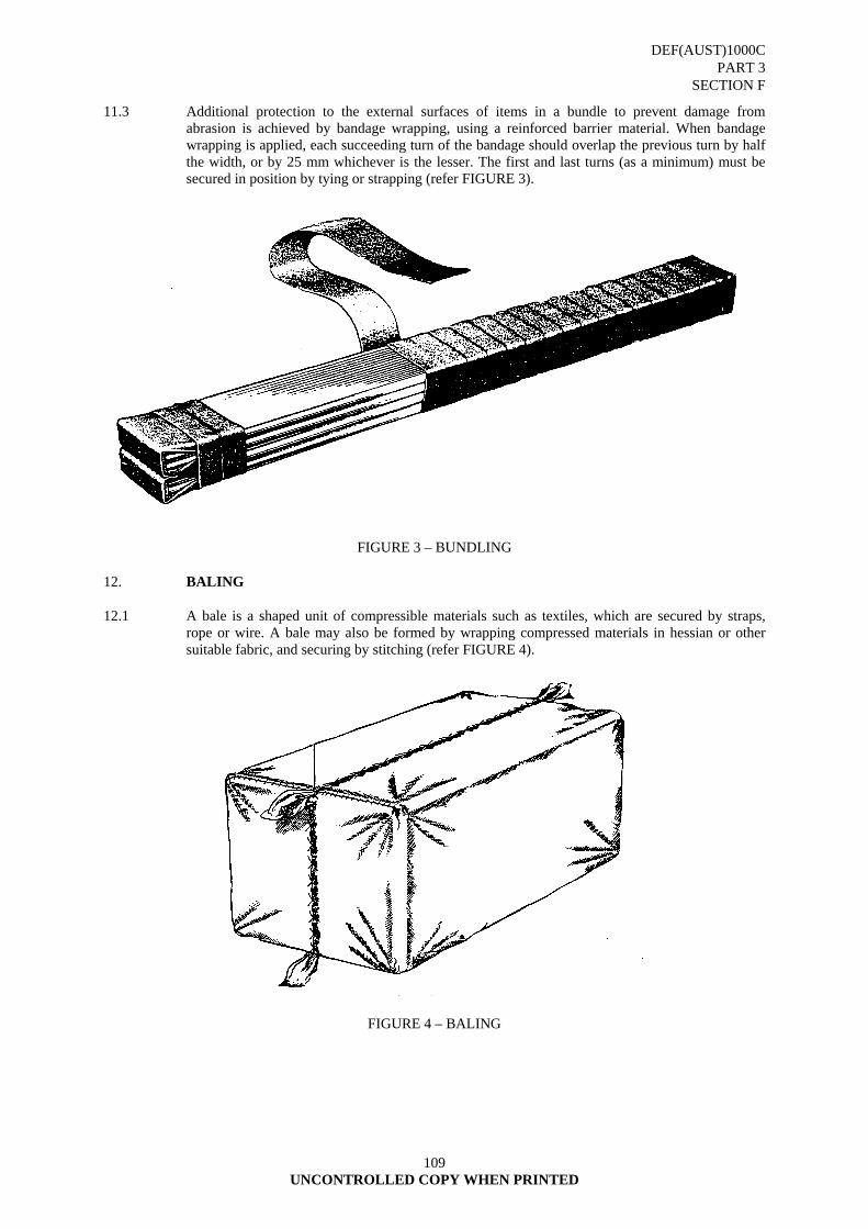
DEF(AUST)1000C PART 3
SECTION F
UNCONTROLLED COPY WHEN PRINTED
109
11.3 Additional protection to the external surfaces of items in a bundle to prevent damage from abrasion is achieved by bandage wrapping, using a reinforced barrier material. When bandage wrapping is applied, each succeeding turn of the bandage should overlap the previous turn by half the width, or by 25 mm whichever is the lesser. The first and last turns (as a minimum) must be secured in position by tying or strapping (refer FIGURE 3).
FIGURE 3 – BUNDLING 12. BALING
12.1 A bale is a shaped unit of compressible materials such as textiles, which are secured by straps, rope or wire. A bale may also be formed by wrapping compressed materials in hessian or other suitable fabric, and securing by stitching (refer FIGURE 4).
FIGURE 4 – BALING
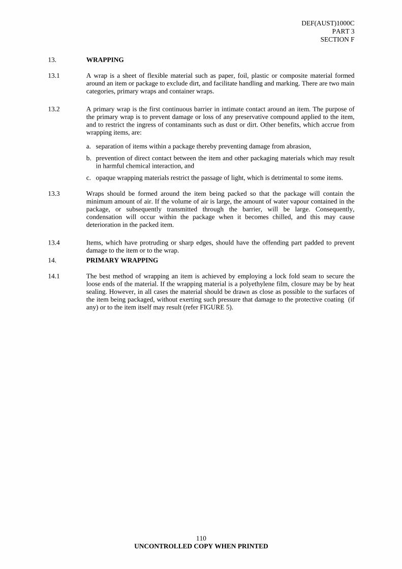
DEF(AUST)1000C PART 3
SECTION F
UNCONTROLLED COPY WHEN PRINTED
110
13. WRAPPING
13.1 A wrap is a sheet of flexible material such as paper, foil, plastic or composite material formed around an item or package to exclude dirt, and facilitate handling and marking. There are two main categories, primary wraps and container wraps.
13.2 A primary wrap is the first continuous barrier in intimate contact around an item. The purpose of the primary wrap is to prevent damage or loss of any preservative compound applied to the item, and to restrict the ingress of contaminants such as dust or dirt. Other benefits, which accrue from wrapping items, are:
a. separation of items within a package thereby preventing damage from abrasion,
b. prevention of direct contact between the item and other packaging materials which may result in harmful chemical interaction, and
c. opaque wrapping materials restrict the passage of light, which is detrimental to some items.
13.3 Wraps should be formed around the item being packed so that the package will contain the minimum amount of air. If the volume of air is large, the amount of water vapour contained in the package, or subsequently transmitted through the barrier, will be large. Consequently, condensation will occur within the package when it becomes chilled, and this may cause deterioration in the packed item.
13.4 Items, which have protruding or sharp edges, should have the offending part padded to prevent damage to the item or to the wrap.
14. PRIMARY WRAPPING
14.1 The best method of wrapping an item is achieved by employing a lock fold seam to secure the loose ends of the material. If the wrapping material is a polyethylene film, closure may be by heat sealing. However, in all cases the material should be drawn as close as possible to the surfaces of the item being packaged, without exerting such pressure that damage to the protective coating (if any) or to the item itself may result (refer FIGURE 5).
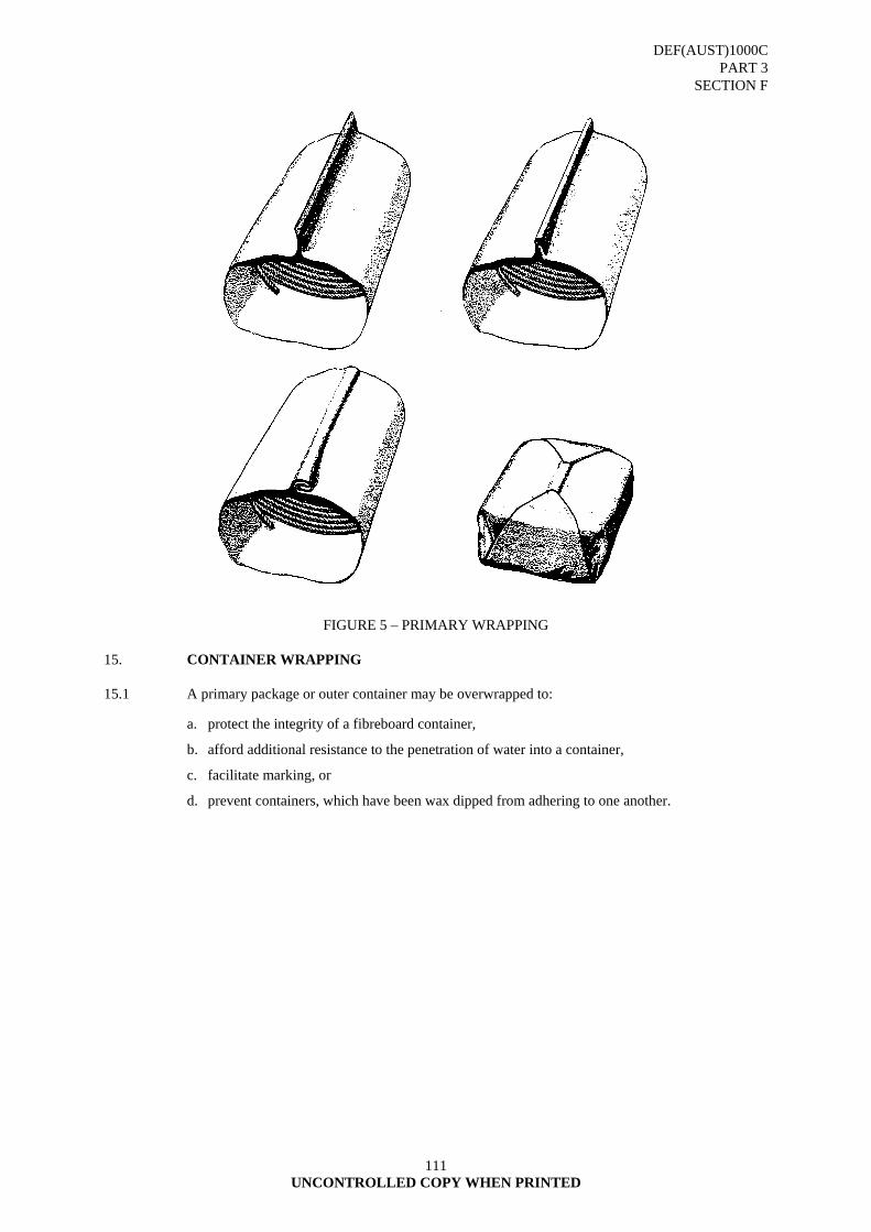
DEF(AUST)1000C PART 3
SECTION F
UNCONTROLLED COPY WHEN PRINTED
111
FIGURE 5 – PRIMARY WRAPPING 15. CONTAINER WRAPPING
15.1 A primary package or outer container may be overwrapped to:
a. protect the integrity of a fibreboard container,
b. afford additional resistance to the penetration of water into a container,
c. facilitate marking, or
d. prevent containers, which have been wax dipped from adhering to one another.
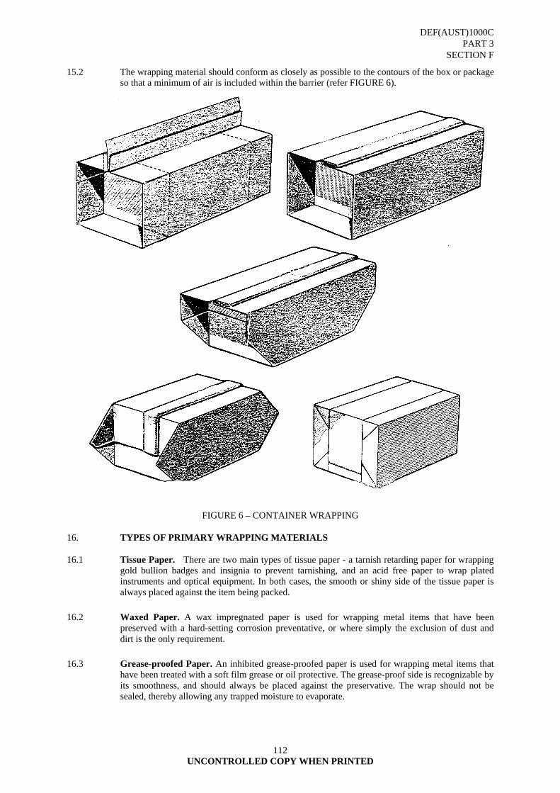
DEF(AUST)1000C PART 3
SECTION F
UNCONTROLLED COPY WHEN PRINTED
112
15.2 The wrapping material should conform as closely as possible to the contours of the box or package so that a minimum of air is included within the barrier (refer FIGURE 6).
FIGURE 6 – CONTAINER WRAPPING 16. TYPES OF PRIMARY WRAPPING MATERIALS
16.1 Tissue Paper. There are two main types of tissue paper - a tarnish retarding paper for wrapping gold bullion badges and insignia to prevent tarnishing, and an acid free paper to wrap plated instruments and optical equipment. In both cases, the smooth or shiny side of the tissue paper is always placed against the item being packed.
16.2 Waxed Paper. A wax impregnated paper is used for wrapping metal items that have been preserved with a hard-setting corrosion preventative, or where simply the exclusion of dust and dirt is the only requirement.
16.3 Grease-proofed Paper. An inhibited grease-proofed paper is used for wrapping metal items that have been treated with a soft film grease or oil protective. The grease-proof side is recognizable by its smoothness, and should always be placed against the preservative. The wrap should not be sealed, thereby allowing any trapped moisture to evaporate.
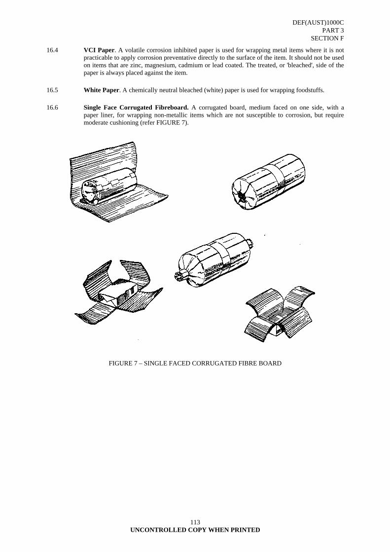
DEF(AUST)1000C PART 3
SECTION F
UNCONTROLLED COPY WHEN PRINTED
113
16.4 VCI Paper. A volatile corrosion inhibited paper is used for wrapping metal items where it is not practicable to apply corrosion preventative directly to the surface of the item. It should not be used on items that are zinc, magnesium, cadmium or lead coated. The treated, or 'bleached', side of the paper is always placed against the item.
16.5 White Paper. A chemically neutral bleached (white) paper is used for wrapping foodstuffs.
16.6 Single Face Corrugated Fibreboard. A corrugated board, medium faced on one side, with a paper liner, for wrapping non-metallic items which are not susceptible to corrosion, but require moderate cushioning (refer FIGURE 7).
FIGURE 7 – SINGLE FACED CORRUGATED FIBRE BOARD
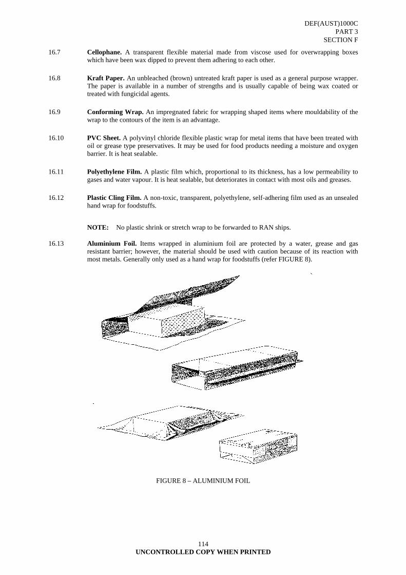
DEF(AUST)1000C PART 3
SECTION F
UNCONTROLLED COPY WHEN PRINTED
114
16.7 Cellophane. A transparent flexible material made from viscose used for overwrapping boxes which have been wax dipped to prevent them adhering to each other.
16.8 Kraft Paper. An unbleached (brown) untreated kraft paper is used as a general purpose wrapper. The paper is available in a number of strengths and is usually capable of being wax coated or treated with fungicidal agents.
16.9 Conforming Wrap. An impregnated fabric for wrapping shaped items where mouldability of the wrap to the contours of the item is an advantage.
16.10 PVC Sheet. A polyvinyl chloride flexible plastic wrap for metal items that have been treated with oil or grease type preservatives. It may be used for food products needing a moisture and oxygen barrier. It is heat sealable.
16.11 Polyethylene Film. A plastic film which, proportional to its thickness, has a low permeability to gases and water vapour. It is heat sealable, but deteriorates in contact with most oils and greases.
16.12 Plastic Cling Film. A non-toxic, transparent, polyethylene, self-adhering film used as an unsealed hand wrap for foodstuffs.
NOTE: No plastic shrink or stretch wrap to be forwarded to RAN ships.
16.13 Aluminium Foil. Items wrapped in aluminium foil are protected by a water, grease and gas resistant barrier; however, the material should be used with caution because of its reaction with most metals. Generally only used as a hand wrap for foodstuffs (refer FIGURE 8).
FIGURE 8 – ALUMINIUM FOIL
DEF(AUST)1000C PART 3
SECTION F
UNCONTROLLED COPY WHEN PRINTED
115
17. CONCLUSION.
17.1 A list of wrapping materials is contained at ANNEX A. The various barrier and wrapping materials for bundling, baling and wrapping are outlined in DEF(AUST)1000, PART 3, SECTION I.
18. BLOCKING AND BRACING
18.1 Blocking and bracing consist of positioning fitments between the strongest areas of the item and the container to distribute the load on both the item and container surfaces, and to avoid stressing weak parts of the item. To reduce the intensity of impact loading to a minimum the bearing areas should be as large as possible compatible with its avoidance of loading on weak points.
18.2 The materials most commonly used are corrugated paper and board, timber, plywood and other wood products. Examples of the use of corrugated paper and board are shown in FIGURES 2 to 8. The material can be applied in many forms to locate an item, e.g. partition, roll, pad, block, strip or cell according to circumstances. Interlocking partitions, as shown in FIGURE 11(b), may be used in conjunction with a space filling material. Die-cut fitments manufactured from corrugated board or chipboard may be used. It should be noted that corrugated paper and board will support considerably higher loads when applied in the direction of the fluting as opposed to normal to the fluting.
18.3 Timber fitments may be secured to the container or assembled around the item. Some typical examples are shown in FIGURES 9 to 12. They may be assembled by nailing, screwing or bolting, and each of these methods may be supplemented by gluing. Nails should be clinched but where this is not possible they should be loaded laterally. The direction of nailing should be arranged so that direct pull is avoided. Nailing or screwing into end grain should also be avoided.
18.4 The method of locating and securing fitments should avoid an internal load being applied to the lid of the container. Typical methods of achieving this are shown in FIGURE 11. An exception to this general rule is where the lid of an inner container is supported by a bulk cushioning material. There is a risk that materiel loaded in the manner illustrated may be damaged when the container is opened. It is therefore necessary to designate which fixings (screws, bolts, etc) are to be removed in order to open the container. These should be clearly marked and opening instructions affixed to the exterior of the container together with a suitable warning marking directing attention to them.
18.5 FIGURE 12 illustrates blocking and bracing of a large item. The transverse members on the top of the item may also be utilized as compression bars, ie. to resist the compressive forces on the top edges of the container when it is being lifted by slings or grabs.
18.6 The attachment of bracing members to the container vertical surfaces should be by cleats (as shown in FIGURES 13(a) and (b)) which should be reinforced where necessary by extra members to transfer local loads to the appropriate corners or corner frames of the container (see FIGURE 13(c)).
18.7 Timber is dimensionally unstable due to variation of moisture content, the maximum effect being across the width, ie. at right angles to the grain. Where a space more than a few centimetres in length is required to be filled the timber member should be used so that the grain is in the direction of the length of the space. Where a large assembly of soft wood components is used, the addition of plywood facing will reduce the tendency to movement and will additionally improve the structural stability and strength of the assembly (see FIGURE 10(a)). Allowance must be made for the thickness of any wrapping or barrier material enclosing the item as this can significantly affect the fit.
18.8 A facing material may be used to prevent direct contact between timber fitments and material and thus minimize abrasion of both the item and any wrapping or barrier which has been applied (see FIGURE 9(b) and 11(b)). The thickness of the facing material should be sufficient to accommodate the slight variations in the fit of the item resulting from its dimensional tolerances
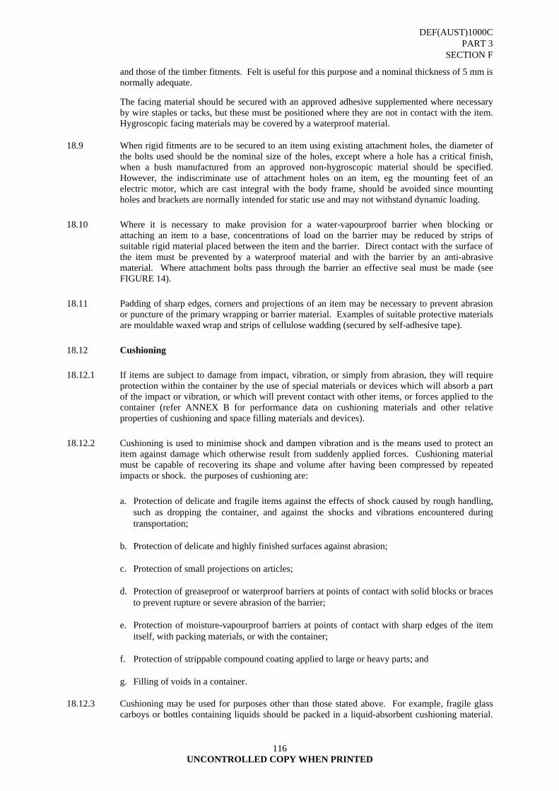
DEF(AUST)1000C PART 3
SECTION F
UNCONTROLLED COPY WHEN PRINTED
116
and those of the timber fitments. Felt is useful for this purpose and a nominal thickness of 5 mm is normally adequate.
The facing material should be secured with an approved adhesive supplemented where necessary by wire staples or tacks, but these must be positioned where they are not in contact with the item. Hygroscopic facing materials may be covered by a waterproof material.
18.9 When rigid fitments are to be secured to an item using existing attachment holes, the diameter of the bolts used should be the nominal size of the holes, except where a hole has a critical finish, when a bush manufactured from an approved non-hygroscopic material should be specified. However, the indiscriminate use of attachment holes on an item, eg the mounting feet of an electric motor, which are cast integral with the body frame, should be avoided since mounting holes and brackets are normally intended for static use and may not withstand dynamic loading.
18.10 Where it is necessary to make provision for a water-vapourproof barrier when blocking or attaching an item to a base, concentrations of load on the barrier may be reduced by strips of suitable rigid material placed between the item and the barrier. Direct contact with the surface of the item must be prevented by a waterproof material and with the barrier by an anti-abrasive material. Where attachment bolts pass through the barrier an effective seal must be made (see FIGURE 14).
18.11 Padding of sharp edges, corners and projections of an item may be necessary to prevent abrasion or puncture of the primary wrapping or barrier material. Examples of suitable protective materials are mouldable waxed wrap and strips of cellulose wadding (secured by self-adhesive tape).
18.12 Cushioning
18.12.1 If items are subject to damage from impact, vibration, or simply from abrasion, they will require protection within the container by the use of special materials or devices which will absorb a part of the impact or vibration, or which will prevent contact with other items, or forces applied to the container (refer ANNEX B for performance data on cushioning materials and other relative properties of cushioning and space filling materials and devices).
18.12.2 Cushioning is used to minimise shock and dampen vibration and is the means used to protect an item against damage which otherwise result from suddenly applied forces. Cushioning material must be capable of recovering its shape and volume after having been compressed by repeated impacts or shock. the purposes of cushioning are:
a. Protection of delicate and fragile items against the effects of shock caused by rough handling,
such as dropping the container, and against the shocks and vibrations encountered during transportation;
b. Protection of delicate and highly finished surfaces against abrasion; c. Protection of small projections on articles; d. Protection of greaseproof or waterproof barriers at points of contact with solid blocks or braces
to prevent rupture or severe abrasion of the barrier; e. Protection of moisture-vapourproof barriers at points of contact with sharp edges of the item
itself, with packing materials, or with the container; f. Protection of strippable compound coating applied to large or heavy parts; and g. Filling of voids in a container.
18.12.3 Cushioning may be used for purposes other than those stated above. For example, fragile glass carboys or bottles containing liquids should be packed in a liquid-absorbent cushioning material.
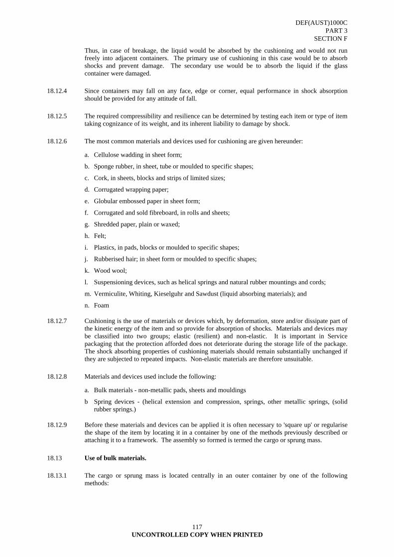
DEF(AUST)1000C PART 3
SECTION F
UNCONTROLLED COPY WHEN PRINTED
117
Thus, in case of breakage, the liquid would be absorbed by the cushioning and would not run freely into adjacent containers. The primary use of cushioning in this case would be to absorb shocks and prevent damage. The secondary use would be to absorb the liquid if the glass container were damaged.
18.12.4 Since containers may fall on any face, edge or corner, equal performance in shock absorption should be provided for any attitude of fall.
18.12.5 The required compressibility and resilience can be determined by testing each item or type of item taking cognizance of its weight, and its inherent liability to damage by shock.
18.12.6 The most common materials and devices used for cushioning are given hereunder:
a. Cellulose wadding in sheet form;
b. Sponge rubber, in sheet, tube or moulded to specific shapes;
c. Cork, in sheets, blocks and strips of limited sizes;
d. Corrugated wrapping paper;
e. Globular embossed paper in sheet form;
f. Corrugated and sold fibreboard, in rolls and sheets;
g. Shredded paper, plain or waxed;
h. Felt;
i. Plastics, in pads, blocks or moulded to specific shapes;
j. Rubberised hair; in sheet form or moulded to specific shapes;
k. Wood wool;
l. Suspensioning devices, such as helical springs and natural rubber mountings and cords;
m. Vermiculite, Whiting, Kieselguhr and Sawdust (liquid absorbing materials); and
n. Foam
18.12.7 Cushioning is the use of materials or devices which, by deformation, store and/or dissipate part of the kinetic energy of the item and so provide for absorption of shocks. Materials and devices may be classified into two groups; elastic (resilient) and non-elastic. It is important in Service packaging that the protection afforded does not deteriorate during the storage life of the package. The shock absorbing properties of cushioning materials should remain substantially unchanged if they are subjected to repeated impacts. Non-elastic materials are therefore unsuitable.
18.12.8 Materials and devices used include the following:
a. Bulk materials - non-metallic pads, sheets and mouldings
b Spring devices - (helical extension and compression, springs, other metallic springs, (solid rubber springs.)
18.12.9 Before these materials and devices can be applied it is often necessary to 'square up' or regularise the shape of the item by locating it in a container by one of the methods previously described or attaching it to a framework. The assembly so formed is termed the cargo or sprung mass.
18.13 Use of bulk materials.
18.13.1 The cargo or sprung mass is located centrally in an outer container by one of the following methods:
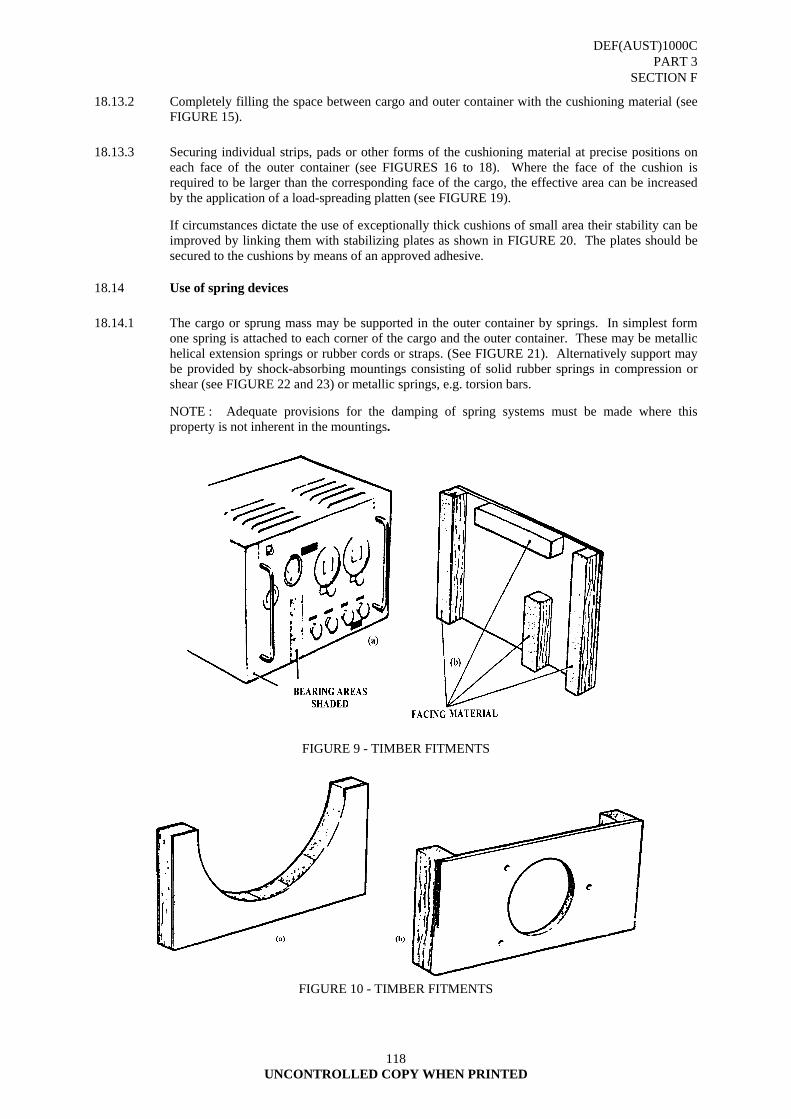
DEF(AUST)1000C PART 3
SECTION F
UNCONTROLLED COPY WHEN PRINTED
118
18.13.2 Completely filling the space between cargo and outer container with the cushioning material (see FIGURE 15).
18.13.3 Securing individual strips, pads or other forms of the cushioning material at precise positions on each face of the outer container (see FIGURES 16 to 18). Where the face of the cushion is required to be larger than the corresponding face of the cargo, the effective area can be increased by the application of a load-spreading platten (see FIGURE 19).
If circumstances dictate the use of exceptionally thick cushions of small area their stability can be improved by linking them with stabilizing plates as shown in FIGURE 20. The plates should be secured to the cushions by means of an approved adhesive.
18.14 Use of spring devices
18.14.1 The cargo or sprung mass may be supported in the outer container by springs. In simplest form one spring is attached to each corner of the cargo and the outer container. These may be metallic helical extension springs or rubber cords or straps. (See FIGURE 21). Alternatively support may be provided by shock-absorbing mountings consisting of solid rubber springs in compression or shear (see FIGURE 22 and 23) or metallic springs, e.g. torsion bars.
NOTE : Adequate provisions for the damping of spring systems must be made where this property is not inherent in the mountings.
FIGURE 9 - TIMBER FITMENTS
FIGURE 10 - TIMBER FITMENTS

DEF(AUST)1000C PART 3
SECTION F
UNCONTROLLED COPY WHEN PRINTED
119
FIGURE 11 - TIMBER FITMENTS
FIGURE 12 BLOCKING AND BRACING A LARGE HEAVY ITEM

DEF(AUST)1000C PART 3
SECTION F
UNCONTROLLED COPY WHEN PRINTED
120
FIGURE 13 ATTACHMENT AND LOCATION OF TIMBER FITMENTS
DEF(AUST)1000C PART 3
SECTION F
UNCONTROLLED COPY WHEN PRINTED
121
FIGURE 14 SEALING THE BARRIER AT ATTACHMENT BOLTS

DEF(AUST)1000C PART 3
SECTION F
UNCONTROLLED COPY WHEN PRINTED
122
FIGURE 15 SELF-LOCATING CUSHION ARRANGEMENT
FIGURE 16
TYPICAL ARRANGEMENT OF SEPARATE CUSHIONS
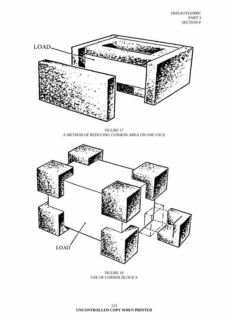
DEF(AUST)1000C PART 3
SECTION F
UNCONTROLLED COPY WHEN PRINTED
123
FIGURE 17 A METHOD OF REDUCING CUSHION AREA ON ONE FACE
FIGURE 18 USE OF CORNER BLOCK S
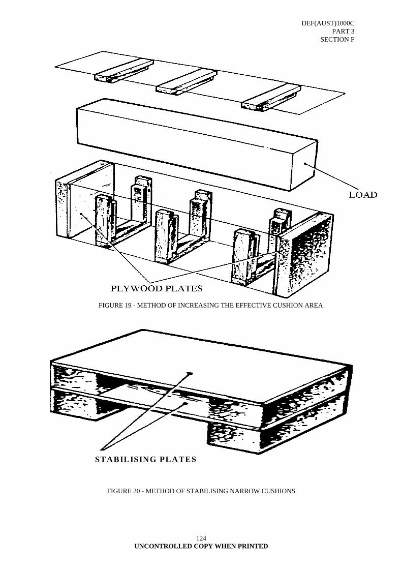
DEF(AUST)1000C PART 3
SECTION F
UNCONTROLLED COPY WHEN PRINTED
124
FIGURE 19 - METHOD OF INCREASING THE EFFECTIVE CUSHION AREA
STABILISING PLATES
FIGURE 20 - METHOD OF STABILISING NARROW CUSHIONS

DEF(AUST)1000C PART 3
SECTION F
UNCONTROLLED COPY WHEN PRINTED
125
FIGURE 21 A SIMPLE SUSPENSION SYSTEM FOR A LIGHT FRAGILE ITEM
FIGURE 22 A HEAVY FRAGILE ITEM MOUNTED ON SOLID RUBBER SHEAR MOUNTINGS
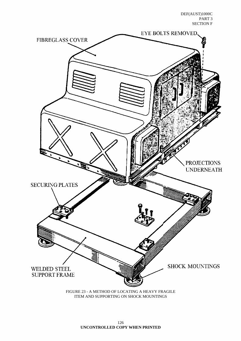
DEF(AUST)1000C PART 3
SECTION F
UNCONTROLLED COPY WHEN PRINTED
126
FIGURE 23 - A METHOD OF LOCATING A HEAVY FRAGILE
ITEM AND SUPPORTING ON SHOCK MOUNTINGS

DEF(AUST)1000C SECTION F
ANNEX A
UNCONTROLLED COPY WHEN PRINTED 127
WRAPPING MATERIALS
ITEM NAME DEFENCE STOCK NO
SPEC/STD NUMBER
CLASS GRADE INTENDED USE
Paper, Wrapping, Tissue (Tarnish Retardant)
8135-66-068-0760 DEF (AUST) 1000 PART 3 SECTION I
1 1 For wrapping of bullion badges and insignia to prevent tarnishing
Paper, Wrapping, Tissue
8135-66-068-0761 DEF (AUST) 1000 PART 3 SECTION I
1 2 For wrapping plated instruments, utensils, cutlery and optical equipment
Paper, Wrapping (Chemically Neutral)
8135-66-067-5661 DEF (AUST) 1000 PART 3 SECTION I
1 3 For use as a general wrapping material
Paper, Wrapping, Kraft Untreated (Heavy Duty)
8135-66-062-1743 DEF (AUST) 1000 PART 3 SECTION I
1 4 General purpose heavy duty wrapping paper for packages where a high strength material is required
Paper, Wrapping, Kraft Untreated (Medium Duty)
8135-66-062-1748 DEF (AUST) 1000 PART 3 SECTION I
1 5 General purpose medium duty wrapping paper for packages where a medium strength material is required
Paper, Wrapping, Kraft Untreated (Light Duty)
8135-66-062-1749 DEF (AUST) 1000 PART 3 SECTION I
1 6 General purpose light duty wrapping paper used for packages where a low strength material is required
Paper, Wrapping, Waxed
8135-66-068-0762 DEF (AUST) 1000 PART 3 SECTION I
1 7 For primary wrapping of Metallic items treated with dry film preservatives and plated/ painted items, eg, PX107, Cadmium Plate, Galvanised
Paper, Volatile Corrosion Inhibitor Treated
8135-66-068-0765 DEF (AUST) 1000 PART 3 SECTION I
1 8 As a primary wrapping material for ferrous metal items which have been treated with temporary corrosion preventatives or have been partly coated with paint
Paper, Wrapping, Vegetable, Parchment
8135-66-067-5660 DEF (AUST) 1000 PART 3 SECTION I
1 9 As a general purpose greaseproof wrapping
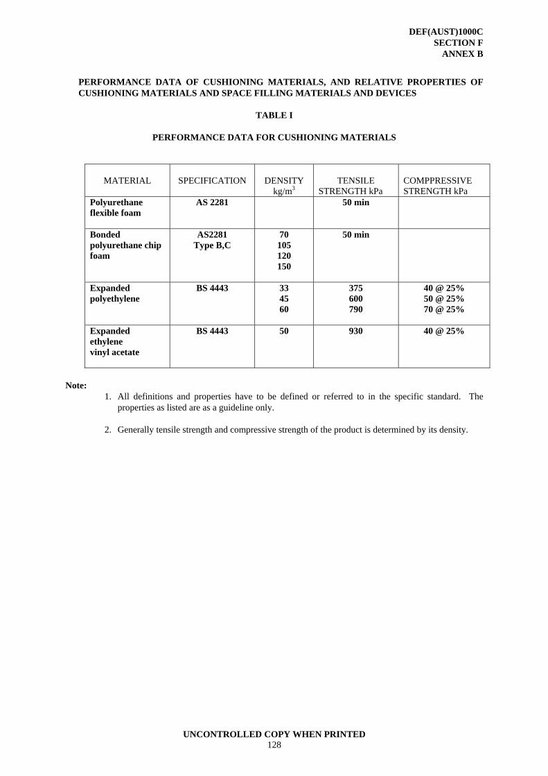
DEF(AUST)1000C SECTION F
ANNEX B
UNCONTROLLED COPY WHEN PRINTED 128
PERFORMANCE DATA OF CUSHIONING MATERIALS, AND RELATIVE PROPERTIES OF CUSHIONING MATERIALS AND SPACE FILLING MATERIALS AND DEVICES
TABLE I
PERFORMANCE DATA FOR CUSHIONING MATERIALS
MATERIAL
SPECIFICATION
DENSITY
kg/m3
TENSILE
STRENGTH kPa
COMPPRESSIVE STRENGTH kPa
Polyurethane flexible foam
AS 2281 50 min
Bonded polyurethane chip foam
AS2281 Type B,C
70 105 120 150
50 min
Expanded polyethylene
BS 4443 33 45 60
375 600 790
40 @ 25% 50 @ 25% 70 @ 25%
Expanded ethylene vinyl acetate
BS 4443 50 930 40 @ 25%
Note: 1. All definitions and properties have to be defined or referred to in the specific standard. The
properties as listed are as a guideline only. 2. Generally tensile strength and compressive strength of the product is determined by its density.
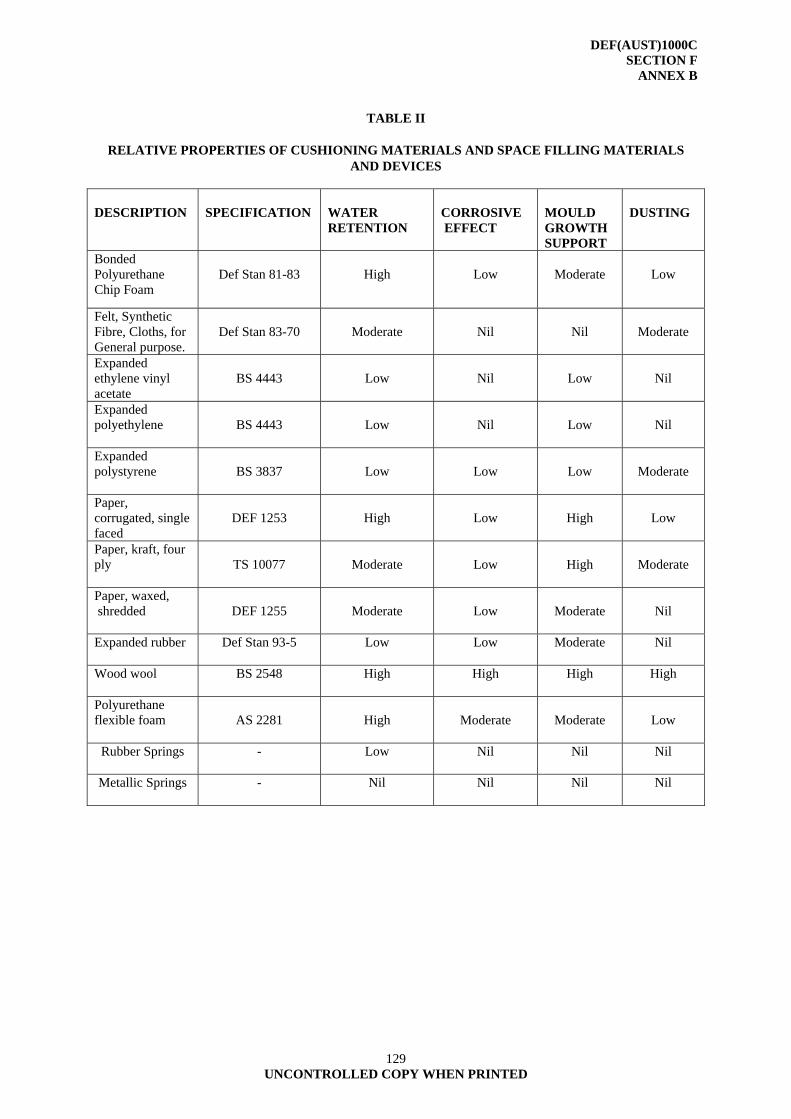
DEF(AUST)1000C SECTION F
ANNEX B
129 UNCONTROLLED COPY WHEN PRINTED
TABLE II
RELATIVE PROPERTIES OF CUSHIONING MATERIALS AND SPACE FILLING MATERIALS
AND DEVICES DESCRIPTION
SPECIFICATION
WATER RETENTION
CORROSIVE EFFECT
MOULD GROWTH SUPPORT
DUSTING
Bonded Polyurethane Chip Foam
Def Stan 81-83
High
Low
Moderate
Low
Felt, Synthetic Fibre, Cloths, for General purpose.
Def Stan 83-70
Moderate
Nil
Nil
Moderate
Expanded ethylene vinyl acetate
BS 4443
Low
Nil
Low
Nil
Expanded polyethylene
BS 4443
Low
Nil
Low
Nil
Expanded polystyrene
BS 3837
Low
Low
Low
Moderate
Paper, corrugated, single faced
DEF 1253
High
Low
High
Low
Paper, kraft, four ply
TS 10077
Moderate
Low
High
Moderate
Paper, waxed, shredded
DEF 1255
Moderate
Low
Moderate
Nil
Expanded rubber
Def Stan 93-5 Low Low Moderate Nil
Wood wool BS 2548
High High High High
Polyurethane flexible foam
AS 2281
High
Moderate
Moderate
Low
Rubber Springs
- Low Nil Nil Nil
Metallic Springs
- Nil Nil Nil Nil
DEF(AUST)1000C PART 3
SECTION G
UNCONTROLLED COPY WHEN PRINTED 130
SECTION G - LINER BOX/CASE; WATER-VAPOUR PROOF OR WATERPROOF;
SPECIFICATION This Section Supersedes DEF(AUST)6119A, Liner Box/Case; Water-Vapour Proof Or Waterproof; Specification 1. SCOPE
1.1 This section details the requirements for the manufacture and closure of water-vapour-proof and waterproof box liners.
1.2 Classification
1.2.1 Box liners shall be classified as one of the following type:
TYPE DATA SHEET LB 1, Liner, Box/Case No 1 LB 2, Liner, Box/Case No 2 LB 3, Liner, Box/Case No 3 LB 4, Liner, Box/Case No 4
2. DEFINITIONS
2.1 For the purposes of this specification the following definitions shall apply:
Liner, Box. An item fabricated from corrugated or solid fibreboard specifically designed to fit snugly within a box covering four or more panels. It is used to increase the wall thickness of the box for added strength and reinforcement.
Liner, Case. An item fabricated from a flexible material, such as paper, paper laminated with asphalt, plastic, or the like designed to fit inside a shipping container. The material has inherent qualities or is treated to protect its contents from entrance of water, dust or contamination or prevent sifting.
Lot. Specifically, a quantity of material all of which was manufactured under identical conditions, and assigned an identifying lot number. Liners shall be divided into lots of 100.
Sample Unit. The basic sample unit shall be three liners selected from each lot and supplied by the contractor as complying in all respects with the requirements of this specification.
3. REQUIREMENTS
3.1 General
3.1.1 The technical requirements for each type of box liner are contained in separate data sheets. These data sheets shall be read in conjunction with the requirements of the specification.
3.2 Adhesive
3.2.1 Adhesives used in fabrication and closure of glued type box liners shall be a suitable water-resistant type of adhesive.
3.3 Dimensions
3.3.1 The finished liner shall conform to the dimensions specified by the Ordering Authority. A tolerance of + or - 6mm shall be permitted on all dimensions.
DEF(AUST)1000C PART 3
SECTION G
131 UNCONTROLLED COPY WHEN PRINTED
3.4 Heat Seal Seams
3.4.1 The heat-sealed seam shall be not less than 6mm wide for opaque barrier materials and not less than 3 mm wide for transparent barrier materials.
3.5 Adhesive Seams
3.5.1 Adhesive seams shall be not less than 40mm wide.
NOTE: Care shall be taken to ensure that adhesive setting times are observed.
3.6 Final Closure of Liners
3.6.1 Sealing the top edges of the liner shall be brought together and sealed by an appropriate method.
3.6.2 Excess air shall be removed by making a small pinhole below the seal line and exhausting the excess air either manually or by vacuum extraction. The pinhole shall then be sealed by the application of a strip of pressure sensitive adhesive tape conforming to AS 1599.
3.7 Precautions
3.7.1 Care shall be taken that:
a. All protruding nails, wood splinters and other sharp protrusions, which may cause damage, are removed.
b. All sharp protrusions or edges on items to be packed are suitably cushioned, and;
c. Nails used in closure of the box do not pierce the liner.
3.8 Liner and Material Testing
3.8.1 The assembled liner shall not show and sign of leaks or moisture content at folds, seams nor any signs of swelling, delamination or visible defects when tested in accordance with Annex A.
3.9 Acceptance Quality Levels
3.9.1 The acceptable quality level (AQL) shall be as follows:
a. Special defects 0.4 percent;
b. Major defects 1.0 percent; and
c. Minor defects 4.0 percent.
3.10 Classification of Defects
3.10.1 The classification of defects is as detailed in Table I.
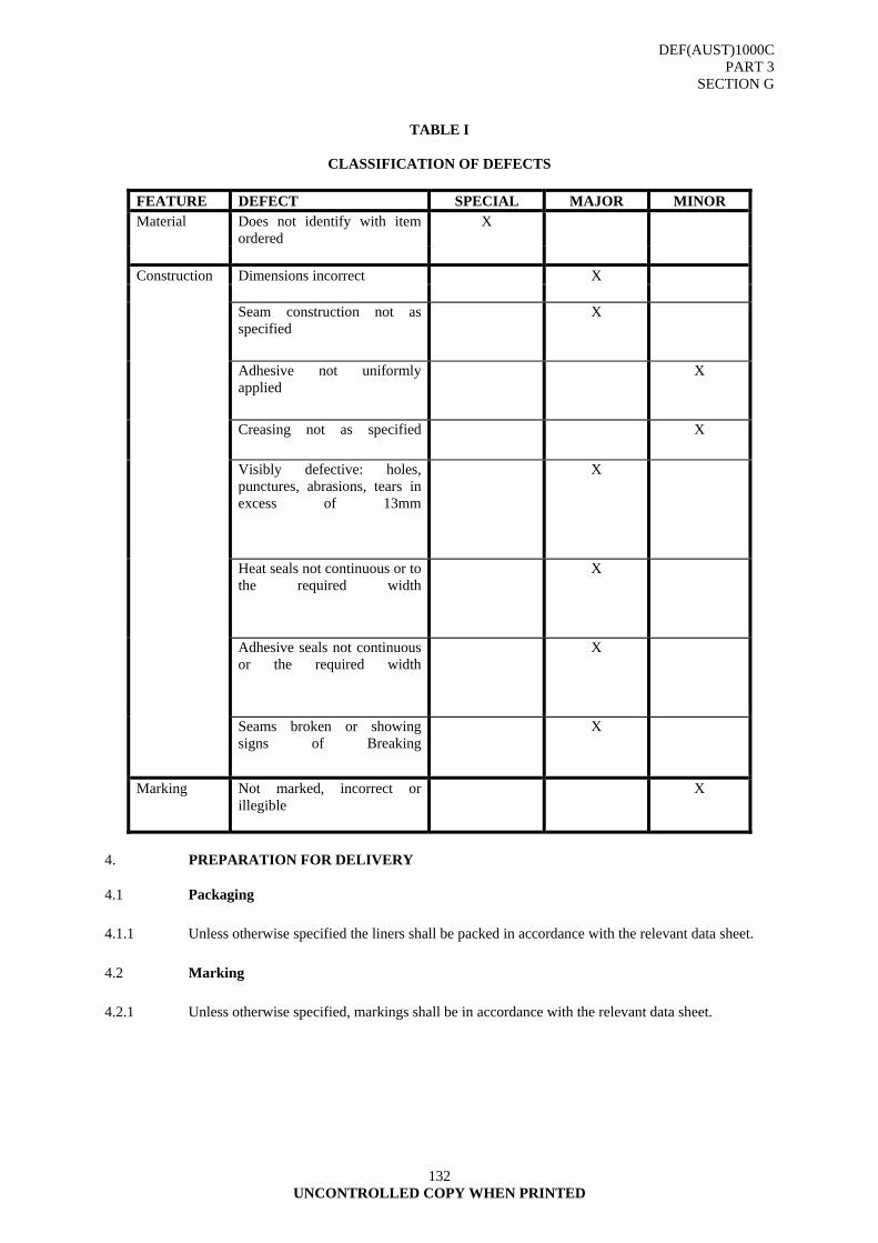
DEF(AUST)1000C PART 3
SECTION G
132 UNCONTROLLED COPY WHEN PRINTED
TABLE I
CLASSIFICATION OF DEFECTS
FEATURE DEFECT SPECIAL MAJOR MINOR Material Does not identify with item
ordered X
Construction Dimensions incorrect X
Seam construction not as specified
X
Adhesive not uniformly applied
X
Creasing not as specified
X
Visibly defective: holes, punctures, abrasions, tears in excess of 13mm
X
Heat seals not continuous or to the required width
X
Adhesive seals not continuous or the required width
X
Seams broken or showing signs of Breaking
X
Marking
Not marked, incorrect or illegible
X
4. PREPARATION FOR DELIVERY
4.1 Packaging
4.1.1 Unless otherwise specified the liners shall be packed in accordance with the relevant data sheet.
4.2 Marking
4.2.1 Unless otherwise specified, markings shall be in accordance with the relevant data sheet.
DEF(AUST)1000C PART 3
SECTION G
133 UNCONTROLLED COPY WHEN PRINTED
ANNEX A
BOX LINER SEAM TEST
A1. PRINCIPLE A1.1 A dye solution is poured into an assembled box liner to test for any leakage through the liner, folds or
seams. A2. PREPARATION A2.1 Prepare a box liner constructed to the relevant Data Sheet for testing. A3. PROCEDURE A3.1 A water solution at room temperature consisting of 0.1 percent of a non-ionic wetting agent and
sufficient dye to produce a distinct colour (such as fluorescein) shall be poured into an assembled liner to a depth of 50mm and left to stand for 15 minutes at room temperature.
A3.2 The liner shall then be tilted so that the solution will cover as much as possible of the vertical heat
sealed seam without spilling and left to stand for 15 minutes. A4. EXPRESSION OF RESULTS A4.1 Report as “Conforms” if no visible sign of dye solution appears at the folds and seams on the exterior. A4.2 The liner shall then be examined and show no sign of swelling, delamination or any other visible
defects. A4.3 Report as “Does not Conform” and the nature of the non-conformity if the sample does not comply
with the rating in A4.1 and A4.2
DEF(AUST)1000C PART 3
SECTION G DATA SHEET No 1
134 UNCONTROLLED COPY WHEN PRINTED
DATA SHEET NO 1
TYPE LB 1, LINER, BOX/CASE
1. SCOPE 1.1 The information contained in this sheet covers the technical requirements for TYPE LB 1,
LINER BOX/CASE and shall be read in conjunction with paragraphs 1 to 7 of this section. 2. APPLICATION 2.1 Box liners are fitted barriers inside transit and storage containers to protect the contents against the
ingress of water and water vapour and to protect material, when packed, against biological attack, contamination and damage.
2.2 Material Code 2.2.1 Code P E Polyethylene film (150 μm Thickness) used as a general-purpose liner for clothing
textiles, and other non-metallic items. 2.2.2 Code WV1 & WV2 Scrim or paper/foil/PE used only as a water vapour proof barrier for optical,
photographic, survey, telecommunication equipment and machinery to prevent the ingress of moisture.
3. REQUIREMENTS 3.1 Materials 3.1.1 Type LB 1 liners shall be manufactured from the materials listed below.
MATERIAL CODE LB 1
Code Material Specification LB1/PE
Polyethylene sheet or tube (Water resistant) BS 7344
LB1/WV1 Paper/foil/polyethylene (Water-vapour proof) MIL-B-131 Class 1
LB1/WV2 Scrim/foil/polyethylene (Water-vapour proof) MIL-B-131 Class 2
3.2 Size of Material 3.2.1 The formula used to determine the size of material shall be: Length= 2L + 2W + 75mm Width = D + W + 75mm 3.2.2 When using layflat tube the following formula shall be used to determine size: Length= D + W + 75mm Width = L + W + 13mm
DEF(AUST)1000C PART 3
SECTION G DATA SHEET No 1
135 UNCONTROLLED COPY WHEN PRINTED
3.3 Fabrication 3.3.1 The liner shall be fabricated in accordance with Figure 1 and as follows: Step 1. Fold sheet in half at line a - b Step 2.. Heat seal along bottom and one edge to form bag Step 3. From the bottom measure up half the width of the box and crease along line c d
Step 4. Measure half the width of the box in from both sides of bag and crease along lines e f and g h. Fold to lay flat condition for delivery and storage
Step 5. Erect liner for use with ears turned up
Step 6. Shows liner closed 4. PACKAGING 4.1 Unless otherwise specified, the liners shall be supplied stacked on edge in fibreboard boxes. 4.2 Marking 4.2.1 Marking shall be in accordance with DEF(AUST)1000, PART 5. In addition to other specified
marking each liner or package of liners shall be marked with the liner code.
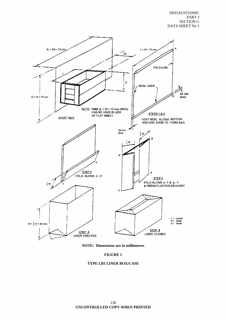
DEF(AUST)1000C PART 3
SECTION G DATA SHEET No 1
136 UNCONTROLLED COPY WHEN PRINTED
NOTE: Dimensions are in millimetres
FIGURE 1
TYPE LB1 LINER BOX/CASE
DEF(AUST)1000C PART 3
SECTION G DATA SHEET No 2
137 UNCONTROLLED COPY WHEN PRINTED
DATA SHEET NO 2
TYPE LB 2, LINER, BOX/CASE 1. SCOPE 1.1 The information contained in this sheet covers the technical requirements for TYPE LB 2
LINER, BOX/CASE and shall be read in conjunction with paragraph 1 to 7 of this section. 2. APPLICATION 2.1 Box liners are fitted barriers inside transit and storage containers to protect the contents against
the ingress of water vapour and to protect material, when packed, against biological attack, contamination and damage.
2.2 Material Code 2.2.1 Code C1 Non-reinforced, bitumen, kraft, used for light easily contoured items. 2.2.2 Code C2 Reinforced, bitumen, kraft, used for heavier items requiring a stronger material than
C1. 3. REQUIREMENTS 3.1 Materials 3.1.1 Type LB 2 liners shall be manufactured from the materials listed below.
MATERIAL CODE LB 2
Code Material Specification LB2/C1 Non-reinforced, bitumen laminated kraft DEF(AUST)1000, PART
3, SECTION H, Class 1
DEF(AUST)1000, PART 3, SECTION H,
LB2/C2 Reinforced, bitumen laminated kraft
Class 2 3.2 Size of Material 3.2.1 The formula used to determine the size of material shall be: Length= 2L + 2W + 75mm or 2(L + 6mm) + 2(W + 6mm) + 50mm Width = D + W + 110mm or (D + 6mm) + (W + 6mm) + 100mm 3.3 Fabrication 3.3.1 The liner shall be fabricated in accordance with Figure 2 and as follows:
Step 1. On the sheet cut to size, measure 50mm in from both ends and across the width of the material, and form two crease lines, bending the material upwards at right angles.
DEF(AUST)1000C PART 3
SECTION G DATA SHEET No 2
138 UNCONTROLLED COPY WHEN PRINTED
Step 2. Form a tube and join the 50mm faces together. Position the seam line in the centre of the length, and smooth the material out toward the edges to form two crease lines (a) and (b).
Step 3. From the crease lines (a) and (b) measure out half the width of the box on each side and
form crease lines (c), (d), (e) and (f). Step 4. From the bottom of the tube measure up half the width of the box plus 50mm, form
crease line (g). Measure from (g) an additional half the width of the box and form crease line (h).
Step 5. Open out base and apply adhesive to form a 50mm wide seal line around the and 6. inside. Step 7. Form seam and allow for setting time. Open liner and inspect for full seam lines and
punctures. Fold flaps toward centre line and glue into position. Remove surplus adhesive and fold to lay flat condition for delivery and storage.
Step 8. Erect liner for use.
4. PACKAGING 4.1 Unless otherwise specified, the liners shall be supplied stacked on edge in fibreboard boxes. 4.1.1 The bituminised liners shall be externally and internally dry when packed as condensation may
cause tar bleeding. 5. MARKING 5.1 Marking shall be accordance with DEF(AUST)1000, PART 5. In addition to other specified
markings each liner or package of liners shall be marked with the liner code.
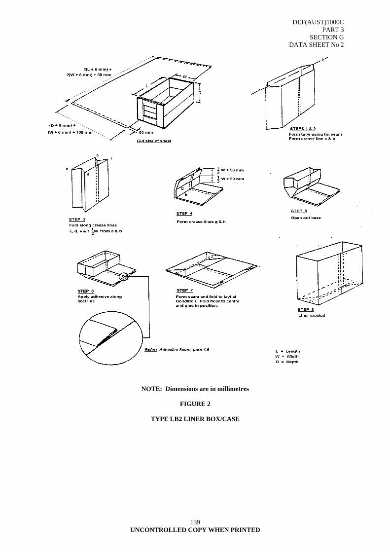
DEF(AUST)1000C PART 3
SECTION G DATA SHEET No 2
139 UNCONTROLLED COPY WHEN PRINTED
NOTE: Dimensions are in millimetres
FIGURE 2
TYPE LB2 LINER BOX/CASE
DEF(AUST)1000C PART 3
SECTION G DATA SHEET No 3
140 UNCONTROLLED COPY WHEN PRINTED
DATA SHEET NO 3
TYPE LB 3, LINER, BOX/CASE 1. SCOPE 1.1 The information contained in this sheet covers the technical requirements for TYPE LB 3
LINER, BOX/CASE and shall be read in conjunction with paragraphs 1 to 7 of this section. 2. APPLICATION 2.1 Box liners are fitted barriers used inside transit and storage containers to protect the contents
against the ingress of water and water vapour and to protect material, when packed, against biological attack, contamination and damage.
2.2 Material Code 2.2.1 Code C2 Reinforced bitumen, kraft, used for heavier items requiring a stronger material than
C1. 2.2.2 Code C3 As for C2 used when heat sealability is required. 2.2.3 Code C7 Reinforced plastic, non-staining laminated kraft non-heat sealable for textiles,
stationary and other items that may be adversely affected by bitumen bleed. 2.2.4 Code C8 Reinforced plastic non-staining, kraft plastic coated heat sealable used specifically
for textile, stationary and light items where staining is not acceptable. 2.2.5 Code WV1 & WV2 Scrim or paper/foil/PE used only as a water vapour-proof barrier for optical,
photographic, survey, telecommunication equipment and machinery to prevent the ingress of moisture.
3. REQUIREMENTS 3.1 Materials 3.1.1 Type LB 3 liners shall be manufactured from the materials listed below:
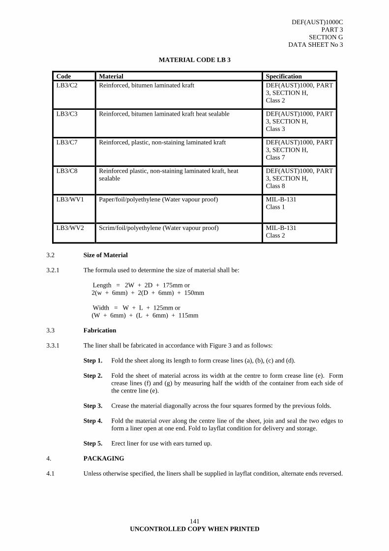
DEF(AUST)1000C PART 3
SECTION G DATA SHEET No 3
141 UNCONTROLLED COPY WHEN PRINTED
MATERIAL CODE LB 3
Code Material Specification LB3/C2 Reinforced, bitumen laminated kraft DEF(AUST)1000, PART
3, SECTION H, Class 2
LB3/C3 Reinforced, bitumen laminated kraft heat sealable DEF(AUST)1000, PART 3, SECTION H, Class 3
LB3/C7 Reinforced, plastic, non-staining laminated kraft DEF(AUST)1000, PART 3, SECTION H, Class 7
LB3/C8 Reinforced plastic, non-staining laminated kraft, heat sealable
DEF(AUST)1000, PART 3, SECTION H, Class 8
LB3/WV1 Paper/foil/polyethylene (Water vapour proof) MIL-B-131 Class 1
LB3/WV2 Scrim/foil/polyethylene (Water vapour proof) MIL-B-131 Class 2
3.2 Size of Material 3.2.1 The formula used to determine the size of material shall be: Length = 2W + 2D + 175mm or 2(w + 6mm) + 2(D + 6mm) + 150mm Width = W + L + 125mm or (W + 6mm) + (L + 6mm) + 115mm 3.3 Fabrication 3.3.1 The liner shall be fabricated in accordance with Figure 3 and as follows: Step 1. Fold the sheet along its length to form crease lines (a), (b), (c) and (d). Step 2. Fold the sheet of material across its width at the centre to form crease line (e). Form
crease lines (f) and (g) by measuring half the width of the container from each side of the centre line (e).
Step 3. Crease the material diagonally across the four squares formed by the previous folds.
Step 4. Fold the material over along the centre line of the sheet, join and seal the two edges to
form a liner open at one end. Fold to layflat condition for delivery and storage. Step 5. Erect liner for use with ears turned up. 4. PACKAGING 4.1 Unless otherwise specified, the liners shall be supplied in layflat condition, alternate ends reversed.
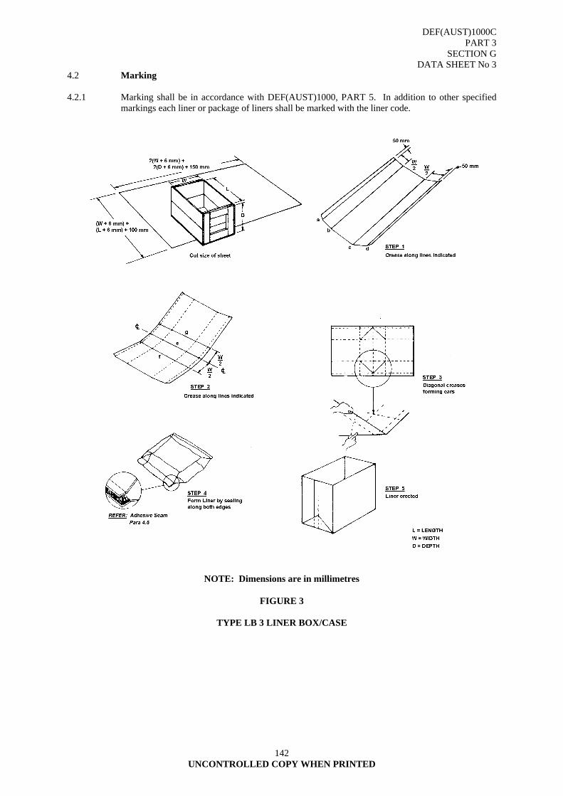
DEF(AUST)1000C PART 3
SECTION G DATA SHEET No 3
142 UNCONTROLLED COPY WHEN PRINTED
4.2 Marking 4.2.1 Marking shall be in accordance with DEF(AUST)1000, PART 5. In addition to other specified
markings each liner or package of liners shall be marked with the liner code.
NOTE: Dimensions are in millimetres
FIGURE 3
TYPE LB 3 LINER BOX/CASE
DEF(AUST)1000C PART 3
SECTION G DATA SHEET No 4
143 UNCONTROLLED COPY WHEN PRINTED
DATA SHEET NO 4
TYPE LB 4, LINER, BOX/CASE
1. SCOPE 1.1 The information contained in this sheet covers the technical requirements for TYPE LB 4
LINER, BOX/CASE and shall be read in conjunction with paragraphs 1 to 7 of this section. 2. APPLICATION 2.1 Box liners are fitted barriers inside transit and storage containers to protect the contents against the
ingress of water and water vapour and to protect material, when packed, against biological attack, contamination and damage.
2.2 Material Code 2.2.1 Code C1 Non-reinforced bitumen, kraft, used for light easily contoured items. 2.2.2 Code C2 Reinforced bitumen kraft, used for heavier items requiring a stronger material than
C1. 2.2.3 Code C6 Reinforced plastic, non-staining, kraft/PE, used as Type LB 4 liners for textiles,
stationary and other items that may be adversely affected by bitumen bleed. 3. REQUIREMENTS 3.1 Materials 3.1.1 Type LB 4 liners shall be manufactured from the materials listed below:
MATERIAL CODE LB 4
Code Material Specification LB4/C1 Non-reinforced, bitumen laminated kraft DEF(AUST)1000, PART
3, SECTION H. Class 1
LB4/C2 Reinforced, bitumen laminated kraft DEF(AUST)1000, PART 3, SECTION H. Class 2
LB4/C6 Heavily reinforced, plastic, non-staining kraft, PE, non-heat sealable
DEF(AUST)1000, PART 3, SECTION H. Class 6
3.2 Size of Material 3.2.1 The formula used to determine the size of material shall be: Lid and bottom = L x W End components = (W + 2T + 6mm) x (D + 2T + 6mm) Side components = L x (D + 2T + 6mm)
DEF(AUST)1000C PART 3
SECTION G DATA SHEET No 4
144 UNCONTROLLED COPY WHEN PRINTED
3.3 Fabrication 3.3.1 The liner shall be fabricated in accordance with Figure 4 and as follows: Step 1. With waterproof adhesive, adhere the sheets of material to their respective components.
Remove all air pockets and lumps from under material. Step 2. During assembly, waterproof adhesive shall be applied between mating surfaces. Unless
otherwise specified, adhesive shall not be applied between the formed box and lid. Remove surplus adhesive.
3.4 Marking 3.4.1 Marking shall be in accordance with specification DEF(AUST)1000, PART 5. In addition to other
specified markings each liner or package of liners shall be marked with the liner code.
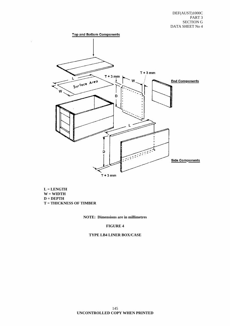
DEF(AUST)1000C PART 3
SECTION G DATA SHEET No 4
145 UNCONTROLLED COPY WHEN PRINTED
L = LENGTH W = WIDTH D = DEPTH T = THICKNESS OF TIMBER
NOTE: Dimensions are in millimetres
FIGURE 4
TYPE LB4 LINER BOX/CASE

DEF(AUST)1000C PART 3
SECTION H PART A
146 UNCONTROLLED COPY WHEN PRINTED
SECTION H - BARRIER MATERIAL
This SECTION is in two parts and supersedes the following documents: DEF(AUST) 5375 Barrier Material Greaseproofed, Waterproofed, Flexible. DEF(AUST) 5358A Barrier Material, Water Proofed, Flexible Packaging Grades; Specifications.
PART A: BARRIER MATERIAL, GREASEPROOFED, WATERPROOFED, FLEXIBLE; SPECIFICATION
1. SCOPE
1.1 This section covers the requirements for greaseproofed, waterproofed, flexible barrier material used as an intimate, mouldable wrap for items coated with preservative oils and greases.
1.2 Intended Use. The material is intended for use as a mouldable intimate wrap for items coated with protective oils and greases. The plastic film component of the combination (the smooth face) will be closest to the surface of the item being wrapped. The material shall form a continuous sealed surface and is usually overcoated by dipping in a hot wax sealing compound. It may be employed without an overcoating of sealing compound. In either case overwrapping with a paper or plastic film is necessary to prevent adhesion.
2. REQUIREMENTS
2.1 Physical Properties. When tested as specified, the barrier material shall conform to the requirements of TABLE I and the other requirements of paragraph 2.
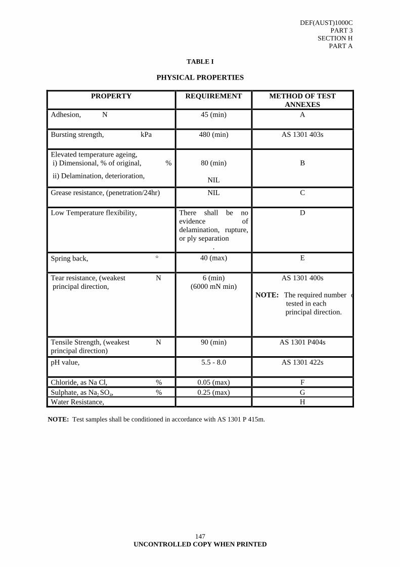
DEF(AUST)1000C PART 3
SECTION H PART A
147 UNCONTROLLED COPY WHEN PRINTED
TABLE I
PHYSICAL PROPERTIES
PROPERTY REQUIREMENT METHOD OF TEST ANNEXES
Adhesion, N 45 (min) A
Bursting strength, kPa 480 (min) AS 1301 403s
Elevated temperature ageing, i) Dimensional, % of original, %
ii) Delamination, deterioration,
80 (min)
NIL
B
Grease resistance, (penetration/24hr) NIL C
Low Temperature flexibility, There shall be no evidence of delamination, rupture, or ply separation
.
D
Spring back, ° 40 (max) E
Tear resistance, (weakest N principal direction,
6 (min) (6000 mN min)
AS 1301 400s
NOTE: The required number o tested in each
principal direction.
Tensile Strength, (weakest N principal direction)
90 (min) AS 1301 P404s
pH value, 5.5 - 8.0 AS 1301 422s
Chloride, as Na Cl, % 0.05 (max) F Sulphate, as Na2 SO4, % 0.25 (max) G Water Resistance, H
NOTE: Test samples shall be conditioned in accordance with AS 1301 P 415m.
DEF(AUST)1000C PART 3
SECTION H PART A
148 UNCONTROLLED COPY WHEN PRINTED
2.2 Storage Stability. The contractor shall provide evidence that the barrier material shall remain in a serviceable condition and shall comply with all physical property requirements of this section for a period of 12 months from the date of delivery providing the material remains unbroached within the original sealed packs and is stored at a temperature of not less than 5oC nor more than 45oC.
2.3 Materials
2.3.1 Construction. The material shall consist of a single ply of plastic film laminated to a woven backing component by a compounded wax. The wax shall be self-adherent and shall be uniformly coated throughout and appear on both sides of the material.
2.3.2 Form. The material shall be supplied in rolls of 100 metres minimum length and in widths of 915 mm + 3 mm. There shall be no more than 2 splices (3 pieces) in each 100 metres and no piece shall be less than 20 metres in length. Splices shall be evenly and neatly made and shall not part or unwind. The material shall be uniformly and smoothly wound on the roll, crinkling and creasing is not acceptable.
2.3.3 Core. The cores shall have an internal diameter of 76 mm + 3 mm. The length of the core shall be not less than 25 mm longer than the width of the material and shall be set equidistant at each end from the material. The core shall be of sufficient rigidity to prevent distortion of the roll under normal conditions of transportation, storage and use.
2.4 Inspection
2.4.1 Acceptable Quality Levels. The acceptable quality levels (AQLS) shall be as follows:
a. Special defects - 1.0 per cent
b. Major defects - 3.0 per cent
c. Minor defects - 5.0 per cent
2.4.2 Classification of Defects. The classification of defects is detailed in TABLE II.
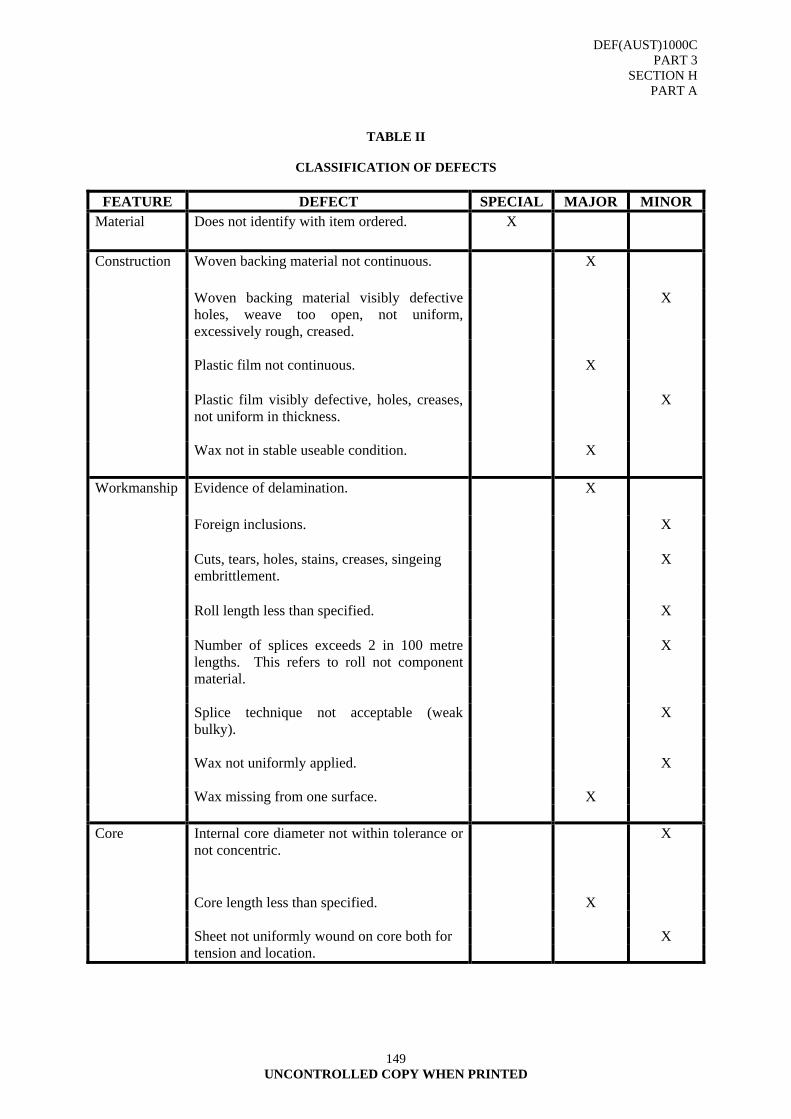
DEF(AUST)1000C PART 3
SECTION H PART A
149 UNCONTROLLED COPY WHEN PRINTED
TABLE II
CLASSIFICATION OF DEFECTS
FEATURE DEFECT SPECIAL MAJOR MINOR
Material Does not identify with item ordered. X
Construction Woven backing material not continuous. X
Woven backing material visibly defective holes, weave too open, not uniform, excessively rough, creased.
X
Plastic film not continuous.
X
Plastic film visibly defective, holes, creases,
not uniform in thickness. X
Wax not in stable useable condition. X
Workmanship Evidence of delamination. X
Foreign inclusions. X
Cuts, tears, holes, stains, creases, singeing embrittlement.
X
Roll length less than specified.
X
Number of splices exceeds 2 in 100 metre
lengths. This refers to roll not component material.
X
Splice technique not acceptable (weak
bulky). X
Wax not uniformly applied. X Wax missing from one surface. X Core Internal core diameter not within tolerance or
not concentric. X
Core length less than specified. X Sheet not uniformly wound on core both for X tension and location.
DEF(AUST)1000C PART 3
SECTION H PART A
150 UNCONTROLLED COPY WHEN PRINTED
3. PREPARATION FOR DELIVERY
3.1 Packaging. Each roll shall be overwrapped with a plastic film, retained in position by tucking the material into the core. The roll shall be suspended within the container to prevent pressure on any portion of the roll surface and to prevent damage to the material. Unless otherwise specified each roll shall be packed in a container approved by the Ordering Authority.
3.2 Marking
3.2.1 Rolls. Unless otherwise specified each roll shall be clearly marked by a stamped imprint or stamped pressure sensitive adhesive label. The detail shall be as follows:
a. NATO Stock Number;
b. approved item name;
c. date of manufacture;
d. number of this specification; and
e. the legend; "Use With Smooth Face Inwards".
3.2.2 Containers. Unless otherwise specified each container shall be marked in accordance with DEF(AUST)1000, PART 5, with the following additional detail:
a. NATO Stock Number;
b. quantity;
c. date of manufacture; and
d. the legend "Stand On End - Keep Cool and Dry".
3.2.3 Defence Stock Number.
8135-66-016-3350.
3.2.4 Trade Names.
3.2.4.1 Conforming Wrap - MIL-PRF-121G Barrier Material, greaseproof, waterproof, flexible, heat-sealable
Type I - Medium duty Type II - Light duty
3.2.5 Known Supplier Australian Inhibitor Pty Ltd 5 Meriton Place CLAYTON SOUTH VIC 3169 Phone: (03) 9544 9064 Facsimile: (03) 9544 9141 E-mail [email protected]
DEF(AUST)1000C PART 3
SECTION H PART A
ANNEX A
151 UNCONTROLLED COPY WHEN PRINTED
ANNEX A TO SECTION H
ADHESION A1. SAMPLING AND SAMPLE PREPARATION A1.1 Cut the required number of 75 by 150 mm samples from each principle direction. A2. PROCEDURE A2.1 Prepare a 100 mm² stainless steel panel, cleaned with solvent, to ensure an uncontaminated surface A2.2 Place a sample on the panel with the smooth face representing the greaseproof side facing away
from the panel with sides of the sample placed equidistant from the side of the panel. Cover the sample with a sheet of 100 µm polyethylene.
A2.3 Adhere the sample to the panel by passing an 88 mm wide rubber covered roller approximately
6 mm thick; having a SHORE durometer hardness scale A of 60 + 5; weighing 7 kg and having a diameter of 125 mm over the area in contact; five times in each direction and at a rate of 75 mm per second.
A2.4 Clamp the uncovered 100 mm end of the panel in the upper jaw of a tensile tester with a maximum
capacity of 45 kg with the jaws set 125 mm apart. Clamp the free end of the sample in the lower jaw. Allow the stressing jaw to operate at 300 mm per minute and record the force in kilograms required to disrupt the combination.
A2.5 Repeat the test using an equal number of prepared sample combinations with the smooth face
representing the greaseproof side intimate to the prepared face of the stainless steel panel. A3. TEST REPORT A3.1 Average the values obtained in both forms of test and report each adhesion value in kilograms.
DEF(AUST)1000C PART 3
SECTION H PART A
ANNEX B
152 UNCONTROLLED COPY WHEN PRINTED
ANNEX B
ELEVATED TEMPERATURE AGEING B1. SAMPLING AND SAMPLE PREPARATION B1.1 Cut two 300 mm square specimens from each sample and mark out a 250 mm square centrally on
each specimen. B2. PROCEDURE B2.1 Condition the specimens by suspending them in a drying oven at a temperature of 60o + 1oC for
168 hours. B2.2 Remove the specimens from the oven and place in a humidity cabinet maintained at 65o + 1oC
and 80 + 5 per cent relative humidity for 168 hours. The air in the cabinet must circulate Sufficiently to maintain the atmosphere surrounding each specimen at a uniform temperature and humidity without moving the samples against each other or to the sides of the cabinet.
B2.3 Condition for a further 24 hours at 20o + 2oC and 65 + 2 per cent relative humidity. B3. TEST REPORT B3.1 Measure the specimens and calculate the percentage change in dimensions; observe any loss of
coating, delamination, rupture, or cracking.
DEF(AUST)1000C PART 3
SECTION H PART A
ANNEX C
153 UNCONTROLLED COPY WHEN PRINTED
ANNEX C
GREASE RESISTANCE TEST C1. REAGENTS C1.1 Turpentine solution. To 100 ml of pure gum turpentine (density 0.860 to 0.875 g/ml at 76oC)
add 5 g of anhydrous calcium chloride and 1 g of a soluble red dye. Decant and seal, shake well and allow to stand for at least 10 hours with occasional shaking. Filter through a dry filter paper immediately before use.
C2. PROCEDURE. C2.1 Take 10 specimens measuring 100 mm by 100 mm and fold each diagonally across the middle
with the grease resisting side in. C2.2 Lay the specimen on a flat surface and gently set a 2.25 kg flat-bottomed mass on the specimen so
that it is centred on, and covers the entire length of the fold. Allow to stand for 30 seconds, remove the mass, open the specimen and refold from the diagonally opposite corners with the reverse side of the paper in, so as to form a crease at right angles to the first crease. Apply the mass as before.
C2.3 Place each specimen, with the grease resisting side up, on a sheet of white paper of convenient
size. Stand a 25 mm length of 25 mm inside diameter glass tubing vertically on the specimen, centred on the crossed crease, and place 5 g of sand (all passing through a sieve conforming to AS 1152, aperture 850 µm and all retained on a sieve conforming to AS 1152, aperture 600 µm) in the tube. Level the sand and remove the tube.
C2.4 By means of a pipette add to the sand 1.1 ml of the turpentine solution. Place a 50 g mass on the
sand to hold the specimen to different positions on the backing paper and examine the uncovered areas of the specimen for signs of staining. The time elapsing between the application of the turpentine and the appearance of the first definite red stain shall be recorded as the penetration time.
DEF(AUST)1000C PART 3
SECTION H PART A
ANNEX D
154 UNCONTROLLED COPY WHEN PRINTED
ANNEX D
LOW TEMPERATURE FLEXIBILITY D1. SAMPLING AND SAMPLE PREPARATION D1.1 Cut a 200 mm by 50 mm sample from each principle direction. D2. PROCEDURE D2.1 Place the two ends of the material together and insert between two rigid parallel metal plates 100
by 38 mm with the long axis of the loop at right angles to the axis of the plates. The edges of the plates shall be rounded to facilitate easy entry; edges shall be smooth and free of burrs to avoid tearing the sample. The folded end for the loop must extend at least 25 mm beyond the edge of the plate. The adjacent faces of the plates shall be a distance apart equivalent to five times the nominal thickness of the material.
D2.2 The complete assembly shall be cooled to a temperature below minus 20oC and maintained at this
temperature for 3 hours. At the end of this period, without removing the assembly from the cold chamber, draw the looped end of the sample rapidly through the plates.
D2.3 Observe the samples for evidence of delamination, rupture, or ply separation.
DEF(AUST)1000C PART 3
SECTION H PART A
ANNEX E
155 UNCONTROLLED COPY WHEN PRINTED
ANNEX E
SPRINGBACK
E1 SAMPLING AND SAMPLE PREPARATION E1.1 Cut five test strips 200 mm by 50 mm from a representative sample in each principle direction of
the material and condition for testing in accordance with AS 1301 P145. E2. PROCEDURE E2.1 Lay the test strips on a hard smooth surface with the greaseproof side upwards. Fold 50 mm of
each strip (without creasing) onto itself with two separate sheets of cellulose or similar films sandwiched between. The cellulose film shall be placed across the entire width of the strip and located to prevent contact of the surfaces of the material being tested.
E2.2 A 0.45 kg flat-bottomed weight, 50 mm in diameter, shall be set gently. After 30 seconds the
weight shall be removed, and after a further 30 seconds, the amount of springback shall be determined with a protractor, care being taken to see that the sheet has not adhered to itself and that it is free to springback.
NOTE: If more than one test sample has a springback of more than 40 degrees, a second batch
comprising ten samples shall be tested. If more than one sample of the second series has a springback in excess of 40 degrees; the material shall be construed as having failed to pass the test.

DEF(AUST)1000C PART 3
SECTION H PART A
ANNEX F
156 UNCONTROLLED COPY WHEN PRINTED
ANNEX F
DETERMINATION OF CHLORIDE F1. PRINCIPLE F1.1 The chloride is precipitated as silver chloride and the opalescence is compared with that of a
standard. This method is used when it is necessary only to ascertain that a sample contains less than the specified maximum for the material.
F2. REAGENTS F2.1 Silver nitrate, 0.25 mol/L. F2.2 Nitric acid, 5 mol/L. F2.3 Standard chloride solution. Dilute 28.2 ml of 0.1 mol/L hydrochloric acid to 1 litre. (1 mL = 0.1
mg chloride). F3. APPARATUS F3.1 Nessler cylinders, 100 mL. F4. PROCEDURE F4.1 Transfer a 50 mL aliquot of sample prepared as in paragraph G3.1 of ANNEX G to a Nessler
cylinder. F4.2 Dilute to 75 mL; add 10 mL of nitric acid and 1 mL of silver nitrate. Dilute to 100 mL and mix
well. F4.3. Prepare a standard by diluting 1 mL of standard chloride solution to 75 mL in a Nessler cylinder;
add 10 mL nitric acid and 1 mL silver nitrate. Dilute to 100 mL and mix well. F4.4. Compare the opalescence of the sample with that of the standard by viewing from above over a
black surface. F4.5. If the opalescence is greater than that of the standard, pour out solution from the sample until
opalescence's match. Measure the heights of solution in each cylinder, otherwise proceed to F5.1. F5. CALCULATIONS F5.1 If the opalescence of the sample is less than that of the standard, report the result as "conforms". F5.2 The chloride content of the sample may be approximately determined by the formula: Chloride, per cent by mass = M x h 1 h2 where M = specification maximum h1 = height of liquid in standard h2 = height of liquid in sample
DEF(AUST)1000C PART 3
SECTION H PART A
ANNEX G
157 UNCONTROLLED COPY WHEN PRINTED
ANNEX G
DETERMINATION OF SULPHATES
G1. PRINCIPLE G1.1 The sulphate is precipitated as barium sulphate which is filtered off, dried and weighed. When
small amounts of sulphate are being determined as an impurity, it is not usually necessary to ignite the barium sulphate, as the error introduced is relatively small.
G2. REAGENTS G2.1 Barium chloride, 122 g/L G2.2 Hydrochloric acid, 5 mol/L G3. PROCEDURE G3.1 Weight 10 + 0.1 g of sample, cut into small pieces, into a 250 mL beaker and boil with 100 mL of
distilled water for 30 minutes. Filter the extract into a 250 mL standard flask. Repeat the extraction twice more with 50 mL lots of distilled water. Cool the flask and dilute the extract to 250 mL with distilled water.
G3.2 Take a 50 mL aliquot of the extract prepared as in paragraph 3.1, dilute to 200 mL with water; add
2 mL hydrochloric acid and heat to boiling. G3.3 Add 5 mL barium chloride solution dropwise while stirring, keep the solution hot for 10 minutes,
then allow it to stand overnight. G3.4 Filter the solution through a weighed No.4 sintered glass crucible and wash the precipitate with
water until free from chloride. G3.5 Dry the precipitate for 1 hour at 105 to 110oC, cool in a desiccator and weigh. G4. CALCULATIONS G4.1 Sulphates (as Na2SO4) % m/m = W x 30.4 Where W = mass of precipitate in grams.
DEF(AUST)1000C PART 3
SECTION H PART A
ANNEX H
158 UNCONTROLLED COPY WHEN PRINTED
ANNEX H
WATER RESISTANCE H1. PROCEDURE H1.1 Fold a 200 mm diameter filter paper and fit it into a 100 mm diameter plain glass funnel. Take a
200 mm diameter sample of the material and fold it in the same manner, creasing it after the second fold under a flat-bottomed 10 kg weight for 30 seconds. Open out the sample and fit it inside the filter paper. The centre folded section of sample shall be held away from the remainder so as to expose a single layer of the sample to the funnel.
H1.2 Fill the funnel to a depth of 75 mm with water of 20° to 30°C, containing any suitable dyestuff. H1.3 After 18 hours examine the filter paper for any evidence of staining of dye due to the penetration
of the water through the sample. The test shall be conducted on both faces of the material.
DEF(AUST)1000C PART 3
SECTION H PART B
159 UNCONTROLLED COPY WHEN PRINTED
PART B: BARRIER MATERIAL, WATER PROOFED, FLEXIBLE PACKAGING GRADES; SPECIFICATION 1. SCOPE
1.1 This section covers the requirement for water resistant, flexible, laminated barrier materials having a high degree of resistance to penetration by water.
1.2 Classification. The material shall be supplied as follows:
Class 1 - Non-reinforced, bitumen laminated kraft
Class 2 - Reinforced, bitumen laminated kraft
Class 3 - Reinforced, bitumen laminated kraft, heat sealable
Class 4 - Heavily reinforced, bitumen laminated kraft
Class 5 - Heavily reinforced, non-staining, plastic laminated, extensible kraft
Class 6 - Reinforced, non-staining, plastic laminated kraft
Class 7 - Reinforced, non-staining plastic laminated kraft, plastic coated, heat sealable 2. REQUIREMENTS
2.1 General
2.1.1 The technical requirements for each type of barrier material are contained in separate Data Sheets. These Data Sheets shall be read in conjunction with the other requirements of this section.
2.2 Storage Stability. The barrier material shall remain in a serviceable condition and comply with all physical property requirements for a period of 12 months from the date of delivery providing the material remains unbroached within the original sealed packs and is stored at a temperature of not less than 5°C or more than 45°C.
2.3 Acceptable Quality Levels
2.3.1 The Acceptable Quality Levels (AQL) shall be as follows:
a. Special defects - 1.5 percent
b. Major defects - 2.5 percent
c. Minor defects - 10.0 percent
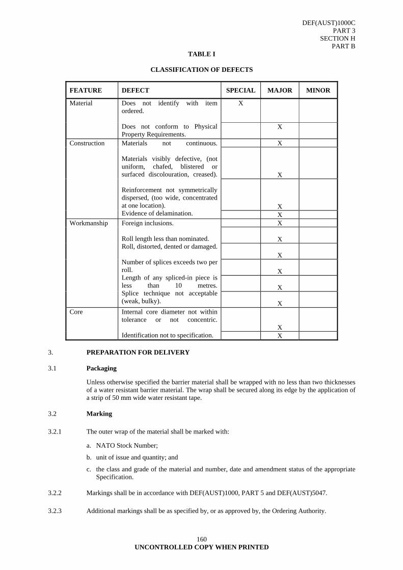
DEF(AUST)1000C PART 3
SECTION H PART B
160 UNCONTROLLED COPY WHEN PRINTED
TABLE I
CLASSIFICATION OF DEFECTS
FEATURE DEFECT SPECIAL MAJOR MINOR
X
Material Does not identify with item ordered. Does not conform to Physical Property Requirements.
X
X
X
X
Construction Materials not continuous. Materials visibly defective, (not uniform, chafed, blistered or surfaced discolouration, creased). Reinforcement not symmetrically dispersed, (too wide, concentrated at one location). Evidence of delamination. X
X
X
X
X
X
Workmanship Foreign inclusions. Roll length less than nominated. Roll, distorted, dented or damaged. Number of splices exceeds two per roll. Length of any spliced-in piece is less than 10 metres.Splice technique not acceptable (weak, bulky).
X
X
Core Internal core diameter not within tolerance or not concentric. Identification not to specification. X
3. PREPARATION FOR DELIVERY
3.1 Packaging
Unless otherwise specified the barrier material shall be wrapped with no less than two thicknesses of a water resistant barrier material. The wrap shall be secured along its edge by the application of a strip of 50 mm wide water resistant tape.
3.2 Marking
3.2.1 The outer wrap of the material shall be marked with:
a. NATO Stock Number;
b. unit of issue and quantity; and
c. the class and grade of the material and number, date and amendment status of the appropriate Specification.
3.2.2 Markings shall be in accordance with DEF(AUST)1000, PART 5 and DEF(AUST)5047.
3.2.3 Additional markings shall be as specified by, or as approved by, the Ordering Authority.
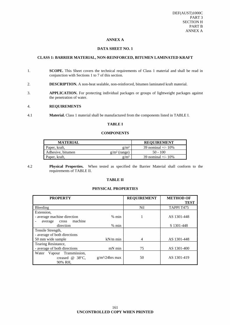
DEF(AUST)1000C PART 3
SECTION H PART B
ANNEX A
161 UNCONTROLLED COPY WHEN PRINTED
ANNEX A
DATA SHEET NO. 1
CLASS 1: BARRIER MATERIAL, NON-REINFORCED, BITUMEN LAMINATED KRAFT
1. SCOPE. This Sheet covers the technical requirements of Class 1 material and shall be read in
conjunction with Sections 1 to 7 of this section. 2. DESCRIPTION. A non-heat sealable, non-reinforced, bitumen laminated kraft material. 3. APPLICATION. For protecting individual packages or groups of lightweight packages against
the penetration of water. 4. REQUIREMENTS 4.1 Material. Class 1 material shall be manufactured from the components listed in TABLE I.
TABLE I
COMPONENTS
MATERIAL REQUIREMENT Paper, kraft, g/m² 39 nominal +/- 10% Adhesive, bitumen g/m² (range) 50 - 100 Paper, kraft, g/m² 39 nominal +/- 10%
4.2 Physical Properties. When tested as specified the Barrier Material shall conform to the
requirements of TABLE II.
TABLE II
PHYSICAL PROPERTIES
PROPERTY REQUIREMENT METHOD OF TEST
Bleeding Nil TAPPI T475 Extension, - average machine direction % min 1 AS 1301-448 - average cross machine
direction
% min
S 1301-448
Tensile Strength, - average of both directions 50 mm wide sample kN/m min 4 AS 1301-448 Tearing Resistance, - average of both directions mN min 75 AS 1301-400 Water Vapour Transmission,
creased @ 38°C, 90% RH,
g/m²/24hrs max
50
AS 1301-419

DEF(AUST)1000C PART 3
SECTION H PART B
ANNEX A
162 UNCONTROLLED COPY WHEN PRINTED
4.3 Rolls. Unless otherwise specified the barrier material shall be supplied in rolls of the sizes listed in TABLE III.
TABLE III
SIZE OF ROLLS
LENGTH METRES
MIN WIDTHS mm NOMINAL CORE INTERNAL DIAMETER
mm 200 600, 900, 1200, 1800, 2400 38 +/- 2
4.3.1 Core. The internal core shall be the full length of the roll and shall be of sufficient rigidity to
prevent distortion under normal conditions of transportation, storage and use. When approved by the Quality Assurance Authority a core plug may be substituted for a full length core. Where used a core plug shall adequately protect the ends of the rolls during transport and storage.
4.3.2 Splices. The number of splices per roll shall not exceed two. The minimum length of a spliced-in
piece shall be not less than 10 metres. 4.3.3 Defence Stock Numbers.
8135-66-141-4755 900 mmm wide
8135-66-141-4756 1200 mm wide
8135-66-141-4757 1500 mm wide.
4.3.3 Trade Names.
Sisalkraft
Light weight; roll size (width) range: 900 mm, 1200 mm, 1800 mm and 2400 mm
Polylam 250
Dubak 700 4.3.4 Known Supplier Australian Inhibitor Pty Ltd 5 Meriton Place CLAYTON SOUTH VIC 3169 Phone: (03) 9544 9064 Facsimile: (03) 9544 9141 E-mail [email protected]
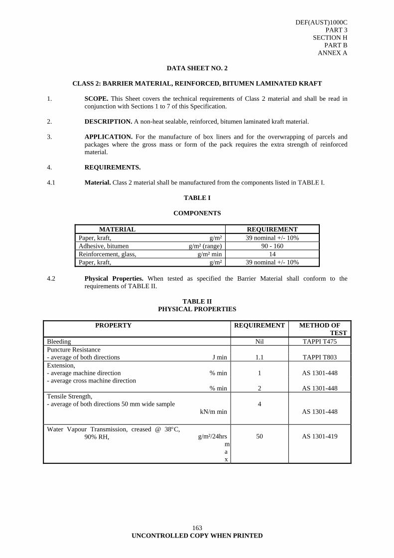
DEF(AUST)1000C PART 3
SECTION H PART B
ANNEX A
163 UNCONTROLLED COPY WHEN PRINTED
DATA SHEET NO. 2
CLASS 2: BARRIER MATERIAL, REINFORCED, BITUMEN LAMINATED KRAFT
1. SCOPE. This Sheet covers the technical requirements of Class 2 material and shall be read in
conjunction with Sections 1 to 7 of this Specification. 2. DESCRIPTION. A non-heat sealable, reinforced, bitumen laminated kraft material. 3. APPLICATION. For the manufacture of box liners and for the overwrapping of parcels and
packages where the gross mass or form of the pack requires the extra strength of reinforced material.
4. REQUIREMENTS. 4.1 Material. Class 2 material shall be manufactured from the components listed in TABLE I.
TABLE I
COMPONENTS
MATERIAL REQUIREMENT Paper, kraft, g/m² 39 nominal +/- 10% Adhesive, bitumen g/m² (range) 90 - 160 Reinforcement, glass, g/m² min 14 Paper, kraft, g/m² 39 nominal +/- 10%
4.2 Physical Properties. When tested as specified the Barrier Material shall conform to the
requirements of TABLE II.
TABLE II PHYSICAL PROPERTIES
PROPERTY REQUIREMENT METHOD OF
TEST Bleeding Nil TAPPI T475 Puncture Resistance - average of both directions J min 1.1 TAPPI T803 Extension, - average machine direction % min 1 AS 1301-448 - average cross machine direction
% min
2
AS 1301-448 Tensile Strength, - average of both directions 50 mm wide sample
kN/m min4
AS 1301-448
Water Vapour Transmission, creased @ 38°C, 90% RH,
g/m²/24hrs
max
50
AS 1301-419
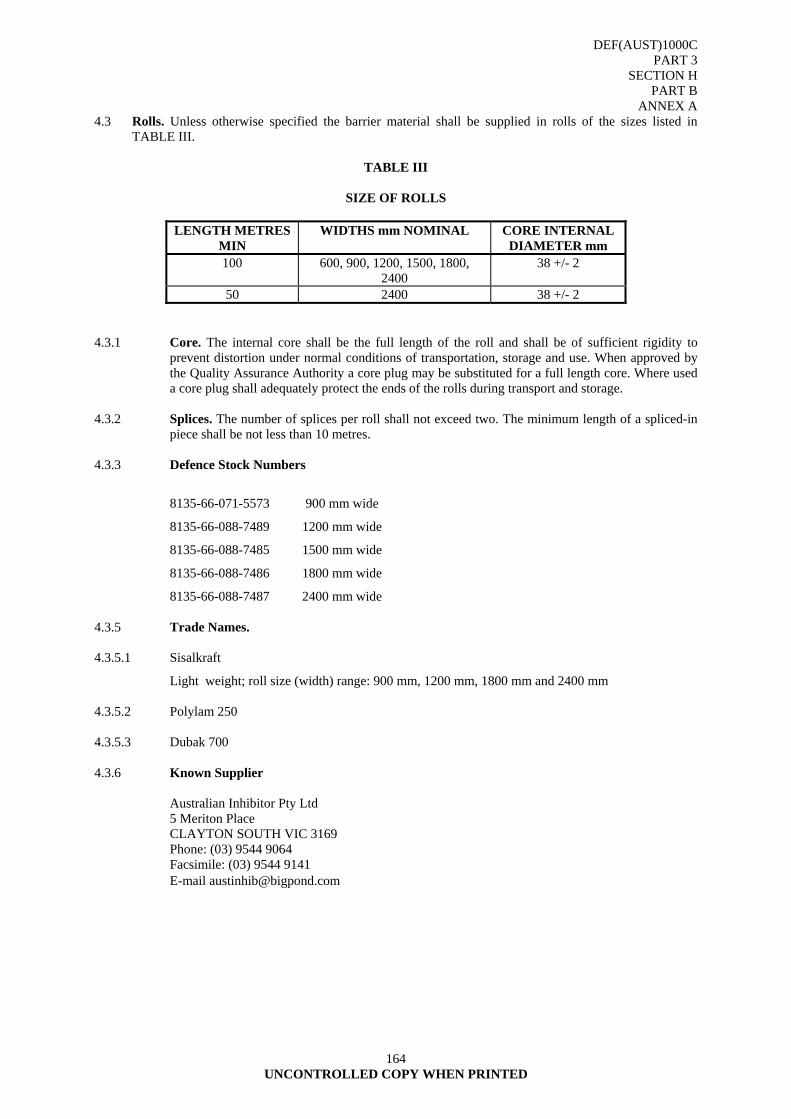
DEF(AUST)1000C PART 3
SECTION H PART B
ANNEX A
164 UNCONTROLLED COPY WHEN PRINTED
4.3 Rolls. Unless otherwise specified the barrier material shall be supplied in rolls of the sizes listed in TABLE III.
TABLE III
SIZE OF ROLLS
LENGTH METRES
MIN WIDTHS mm NOMINAL CORE INTERNAL
DIAMETER mm 100 600, 900, 1200, 1500, 1800,
2400 38 +/- 2
50 2400 38 +/- 2 4.3.1 Core. The internal core shall be the full length of the roll and shall be of sufficient rigidity to
prevent distortion under normal conditions of transportation, storage and use. When approved by the Quality Assurance Authority a core plug may be substituted for a full length core. Where used a core plug shall adequately protect the ends of the rolls during transport and storage.
4.3.2 Splices. The number of splices per roll shall not exceed two. The minimum length of a spliced-in
piece shall be not less than 10 metres. 4.3.3 Defence Stock Numbers
8135-66-071-5573 900 mm wide
8135-66-088-7489 1200 mm wide
8135-66-088-7485 1500 mm wide
8135-66-088-7486 1800 mm wide
8135-66-088-7487 2400 mm wide 4.3.5 Trade Names. 4.3.5.1 Sisalkraft
Light weight; roll size (width) range: 900 mm, 1200 mm, 1800 mm and 2400 mm 4.3.5.2 Polylam 250 4.3.5.3 Dubak 700 4.3.6 Known Supplier Australian Inhibitor Pty Ltd 5 Meriton Place CLAYTON SOUTH VIC 3169 Phone: (03) 9544 9064 Facsimile: (03) 9544 9141 E-mail [email protected]
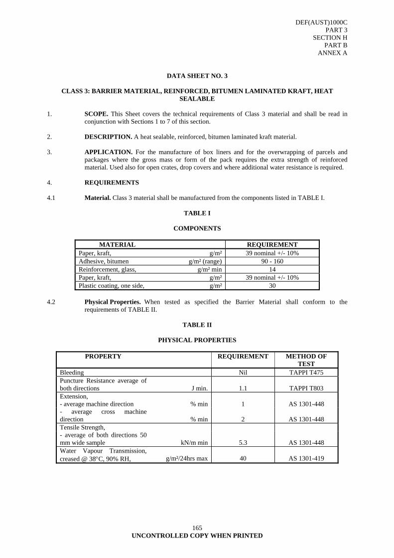
DEF(AUST)1000C PART 3
SECTION H PART B
ANNEX A
165 UNCONTROLLED COPY WHEN PRINTED
DATA SHEET NO. 3
CLASS 3: BARRIER MATERIAL, REINFORCED, BITUMEN LAMINATED KRAFT, HEAT SEALABLE
1. SCOPE. This Sheet covers the technical requirements of Class 3 material and shall be read in
conjunction with Sections 1 to 7 of this section. 2. DESCRIPTION. A heat sealable, reinforced, bitumen laminated kraft material. 3. APPLICATION. For the manufacture of box liners and for the overwrapping of parcels and
packages where the gross mass or form of the pack requires the extra strength of reinforced material. Used also for open crates, drop covers and where additional water resistance is required.
4. REQUIREMENTS 4.1 Material. Class 3 material shall be manufactured from the components listed in TABLE I.
TABLE I
COMPONENTS
MATERIAL REQUIREMENT Paper, kraft, g/m² 39 nominal +/- 10% Adhesive, bitumen g/m² (range) 90 - 160 Reinforcement, glass, g/m² min 14 Paper, kraft, g/m² 39 nominal +/- 10% Plastic coating, one side, g/m² 30
4.2 Physical Properties. When tested as specified the Barrier Material shall conform to the
requirements of TABLE II.
TABLE II
PHYSICAL PROPERTIES
PROPERTY REQUIREMENT METHOD OF TEST
Bleeding Nil TAPPI T475 Puncture Resistance average of both directions J min.
1.1
TAPPI T803
Extension, - average machine direction % min 1 AS 1301-448 - average cross machine direction % min
2
AS 1301-448
Tensile Strength, - average of both directions 50 mm wide sample kN/m min
5.3
AS 1301-448
Water Vapour Transmission, creased @ 38°C, 90% RH, g/m²/24hrs max
40
AS 1301-419
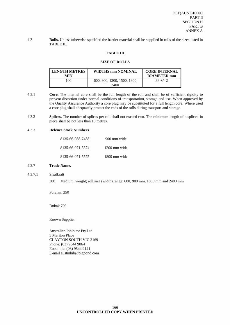
DEF(AUST)1000C PART 3
SECTION H PART B
ANNEX A
166 UNCONTROLLED COPY WHEN PRINTED
4.3 Rolls. Unless otherwise specified the barrier material shall be supplied in rolls of the sizes listed in
TABLE III.
TABLE III
SIZE OF ROLLS
LENGTH METRES MIN
WIDTHS mm NOMINAL CORE INTERNAL DIAMETER mm
100 600, 900, 1200, 1500, 1800, 2400
38 +/- 2
4.3.1 Core. The internal core shall be the full length of the roll and shall be of sufficient rigidity to
prevent distortion under normal conditions of transportation, storage and use. When approved by the Quality Assurance Authority a core plug may be substituted for a full length core. Where used a core plug shall adequately protect the ends of the rolls during transport and storage.
4.3.2 Splices. The number of splices per roll shall not exceed two. The minimum length of a spliced-in
piece shall be not less than 10 metres. 4.3.3 Defence Stock Numbers 8135-66-088-7488 900 mm wide 8135-66-071-5574 1200 mm wide 8135-66-071-5575 1800 mm wide 4.3.7 Trade Name. 4.3.7.1 Sisalkraft
300 Medium weight; roll size (width) range: 600, 900 mm, 1800 mm and 2400 mm
Polylam 250
Dubak 700
Known Supplier
Australian Inhibitor Pty Ltd 5 Meriton Place CLAYTON SOUTH VIC 3169 Phone: (03) 9544 9064 Facsimile: (03) 9544 9141 E-mail [email protected]

DEF(AUST)1000C PART 3
SECTION H PART B
ANNEX A
167 UNCONTROLLED COPY WHEN PRINTED
DATA SHEET NO. 4
CLASS 4: BARRIER MATERIAL, HEAVILY REINFORCED, BITUMEN LAMINATED KRAFT 1. SCOPE. This Sheet covers the technical requirements of Class 4 material and shall be read in
conjunction with Sections 1 to 7 of this section. 2. DESCRIPTION. A non-heat sealable, heavily reinforced, bitumen laminated kraft material. 3. APPLICATION. Used for baling, bandage wrapping, open crates and temporary covers. 4. REQUIREMENTS 4.1 Material. Class 4 material shall be manufactured from the components listed in TABLE I.
TABLE I
COMPONENTS
MATERIAL REQUIREMENT Paper, kraft, g/m² 39 nominal +/- 10% Adhesive, bitumen g/m² (range) 90 - 110 Reinforcement, glass, - Filaments, PP weave
g/m² min 83
4.2 Physical Properties. When tested as specified the Barrier Material shall conform to the requirements of TABLE II.
TABLE II
PHYSICAL PROPERTIES
PROPERTY REQUIREMENT METHOD OF
TEST Bleeding Nil TAPPI T475 Puncture Resistance - average of both directions J min 4.2 TAPPI T803 Extension, - average machine direction % min 1 AS 1301-448 - average cross machine direction % min
2
AS 1301-448
Tensile Strength, - average of both directions 50 mm wide sample kN/m min
5.3
AS 1301-448
Water Vapour Transmission, creased @ 38°C, 90% RH, g/m²/24hrs max 100 AS 1301-419
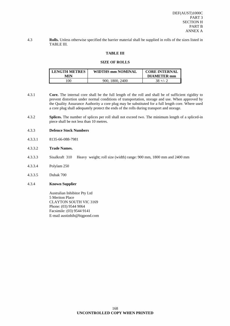
DEF(AUST)1000C PART 3
SECTION H PART B
ANNEX A
168 UNCONTROLLED COPY WHEN PRINTED
4.3 Rolls. Unless otherwise specified the barrier material shall be supplied in rolls of the sizes listed in
TABLE III.
TABLE III
SIZE OF ROLLS
LENGTH METRES MIN
WIDTHS mm NOMINAL CORE INTERNAL DIAMETER mm
100 900, 1800, 2400 38 +/- 2 4.3.1 Core. The internal core shall be the full length of the roll and shall be of sufficient rigidity to
prevent distortion under normal conditions of transportation, storage and use. When approved by the Quality Assurance Authority a core plug may be substituted for a full length core. Where used a core plug shall adequately protect the ends of the rolls during transport and storage.
4.3.2 Splices. The number of splices per roll shall not exceed two. The minimum length of a spliced-in
piece shall be not less than 10 metres. 4.3.3 Defence Stock Numbers 4.3.3.1 8135-66-088-7981 4.3.3.2 Trade Names. 4.3.3.3 Sisalkraft 310 Heavy weight; roll size (width) range: 900 mm, 1800 mm and 2400 mm 4.3.3.4 Polylam 250 4.3.3.5 Dubak 700 4.3.4 Known Supplier Australian Inhibitor Pty Ltd 5 Meriton Place CLAYTON SOUTH VIC 3169 Phone: (03) 9544 9064 Facsimile: (03) 9544 9141 E-mail [email protected]
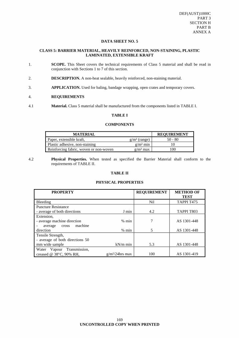
DEF(AUST)1000C PART 3
SECTION H PART B
ANNEX A
169 UNCONTROLLED COPY WHEN PRINTED
DATA SHEET NO. 5
CLASS 5: BARRIER MATERIAL, HEAVILY REINFORCED, NON-STAINING, PLASTIC
LAMINATED, EXTENSIBLE KRAFT 1. SCOPE. This Sheet covers the technical requirements of Class 5 material and shall be read in
conjunction with Sections 1 to 7 of this section. 2. DESCRIPTION. A non-heat sealable, heavily reinforced, non-staining material. 3. APPLICATION. Used for baling, bandage wrapping, open crates and temporary covers. 4. REQUIREMENTS 4.1 Material. Class 5 material shall be manufactured from the components listed in TABLE I.
TABLE I
COMPONENTS
MATERIAL REQUIREMENT Paper, extensible kraft, g/m² (range) 50 - 80 Plastic adhesive, non-staining g/m² min 10 Reinforcing fabric, woven or non-woven g/m² max 100
4.2 Physical Properties. When tested as specified the Barrier Material shall conform to the
requirements of TABLE II.
TABLE II
PHYSICAL PROPERTIES
PROPERTY REQUIREMENT METHOD OF TEST
Bleeding Nil TAPPI T475 Puncture Resistance - average of both directions J min 4.2 TAPPI T803 Extension, - average machine direction % min 7 AS 1301-448 - average cross machine direction % min
5
AS 1301-448
Tensile Strength, - average of both directions 50 mm wide sample kN/m min
5.3
AS 1301-448
Water Vapour Transmission, creased @ 38°C, 90% RH, g/m²/24hrs max
100
AS 1301-419
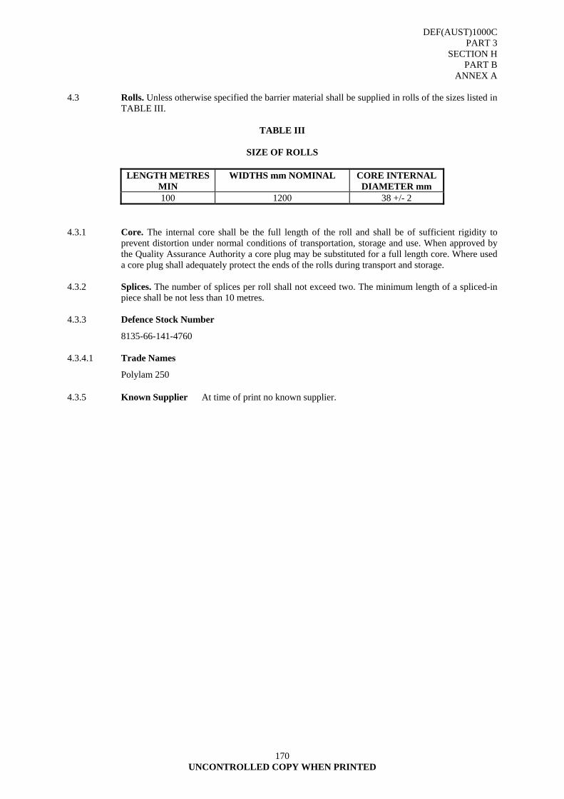
DEF(AUST)1000C PART 3
SECTION H PART B
ANNEX A
170 UNCONTROLLED COPY WHEN PRINTED
4.3 Rolls. Unless otherwise specified the barrier material shall be supplied in rolls of the sizes listed in
TABLE III.
TABLE III
SIZE OF ROLLS
LENGTH METRES MIN
WIDTHS mm NOMINAL CORE INTERNAL DIAMETER mm
100 1200 38 +/- 2 4.3.1 Core. The internal core shall be the full length of the roll and shall be of sufficient rigidity to
prevent distortion under normal conditions of transportation, storage and use. When approved by the Quality Assurance Authority a core plug may be substituted for a full length core. Where used a core plug shall adequately protect the ends of the rolls during transport and storage.
4.3.2 Splices. The number of splices per roll shall not exceed two. The minimum length of a spliced-in
piece shall be not less than 10 metres. 4.3.3 Defence Stock Number
8135-66-141-4760 4.3.4.1 Trade Names
Polylam 250 4.3.5 Known Supplier At time of print no known supplier.

DEF(AUST)1000C PART 3
SECTION H PART B
ANNEX A
171 UNCONTROLLED COPY WHEN PRINTED
DATA SHEET NO. 6
CLASS 6: BARRIER MATERIAL, REINFORCED, NON-STAINING, PLASTIC LAMINATED KRAFT 1. SCOPE. This Sheet covers the technical requirements of Class 6 material and shall be read in
conjunction with Sections 1 to 7 of this section. 2. DESCRIPTION. A non-heat sealable, reinforced, non-staining material. 3. APPLICATION. Used as an interior wrap for textiles, stationery and light items where staining is
not acceptable. 4. REQUIREMENTS
4.1 Material. Class 6 material shall be manufactured from the components listed in TABLE I.
TABLE I
COMPONENTS
MATERIAL REQUIREMENT Paper, kraft, g/m² 39 nominal +/- 10% Adhesive, LDPE g/m² (range) 20 - 30 Reinforcement, glass, g/m² min 7 Paper, kraft, g/m² 39 nominal +/- 10%
4.2 Physical Properties. When tested as specified the Barrier Material shall conform to the
requirements of TABLE II.
TABLE II
PHYSICAL PROPERTIES
PROPERTY REQUIREMENT METHOD OF TEST
Puncture Resistance - average of both directions J min 0.9 TAPPI T803 Extension, - average machine direction % min 1 AS 1301-448 - average cross machine direction % min
2
AS 1301-448
Tensile Strength, - average of both directions 50 mm wide sample kN/m min
5.3
AS 1301-448
Water Vapour Transmission, creased @ 38°C, 90% RH, g/m²/24hrs max 50 AS 1301-419
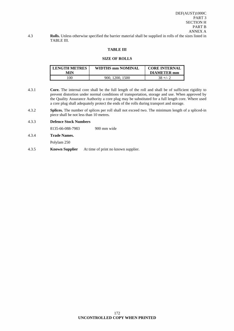
DEF(AUST)1000C PART 3
SECTION H PART B
ANNEX A
172 UNCONTROLLED COPY WHEN PRINTED
4.3 Rolls. Unless otherwise specified the barrier material shall be supplied in rolls of the sizes listed in TABLE III.
TABLE III
SIZE OF ROLLS
LENGTH METRES
MIN WIDTHS mm NOMINAL CORE INTERNAL
DIAMETER mm 100 900, 1200, 1500 38 +/- 2
4.3.1 Core. The internal core shall be the full length of the roll and shall be of sufficient rigidity to prevent distortion under normal conditions of transportation, storage and use. When approved by the Quality Assurance Authority a core plug may be substituted for a full length core. Where used a core plug shall adequately protect the ends of the rolls during transport and storage.
4.3.2 Splices. The number of splices per roll shall not exceed two. The minimum length of a spliced-in piece shall be not less than 10 metres.
4.3.3 Defence Stock Numbers
8135-66-088-7983 900 mm wide
4.3.4 Trade Names.
Polylam 250
4.3.5 Known Supplier At time of print no known supplier.
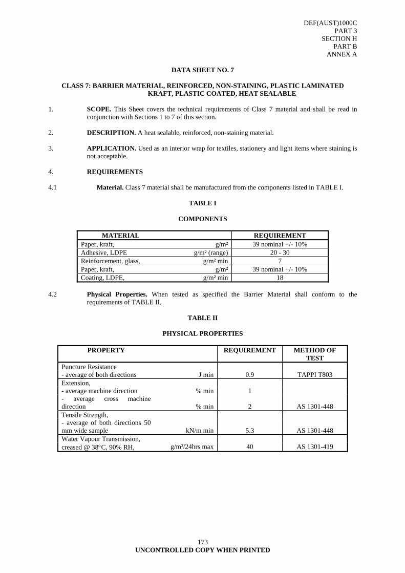
DEF(AUST)1000C PART 3
SECTION H PART B
ANNEX A
173 UNCONTROLLED COPY WHEN PRINTED
DATA SHEET NO. 7
CLASS 7: BARRIER MATERIAL, REINFORCED, NON-STAINING, PLASTIC LAMINATED
KRAFT, PLASTIC COATED, HEAT SEALABLE 1. SCOPE. This Sheet covers the technical requirements of Class 7 material and shall be read in
conjunction with Sections 1 to 7 of this section. 2. DESCRIPTION. A heat sealable, reinforced, non-staining material. 3. APPLICATION. Used as an interior wrap for textiles, stationery and light items where staining is
not acceptable. 4. REQUIREMENTS 4.1 Material. Class 7 material shall be manufactured from the components listed in TABLE I.
TABLE I
COMPONENTS
MATERIAL REQUIREMENT Paper, kraft, g/m² 39 nominal +/- 10% Adhesive, LDPE g/m² (range) 20 - 30 Reinforcement, glass, g/m² min 7 Paper, kraft, g/m² 39 nominal +/- 10% Coating, LDPE, g/m² min 18
4.2 Physical Properties. When tested as specified the Barrier Material shall conform to the
requirements of TABLE II.
TABLE II
PHYSICAL PROPERTIES
PROPERTY REQUIREMENT METHOD OF TEST
Puncture Resistance - average of both directions J min 0.9 TAPPI T803 Extension, - average machine direction % min 1 - average cross machine direction % min
2
AS 1301-448
Tensile Strength, - average of both directions 50 mm wide sample kN/m min
5.3
AS 1301-448
Water Vapour Transmission, creased @ 38°C, 90% RH, g/m²/24hrs max 40 AS 1301-419
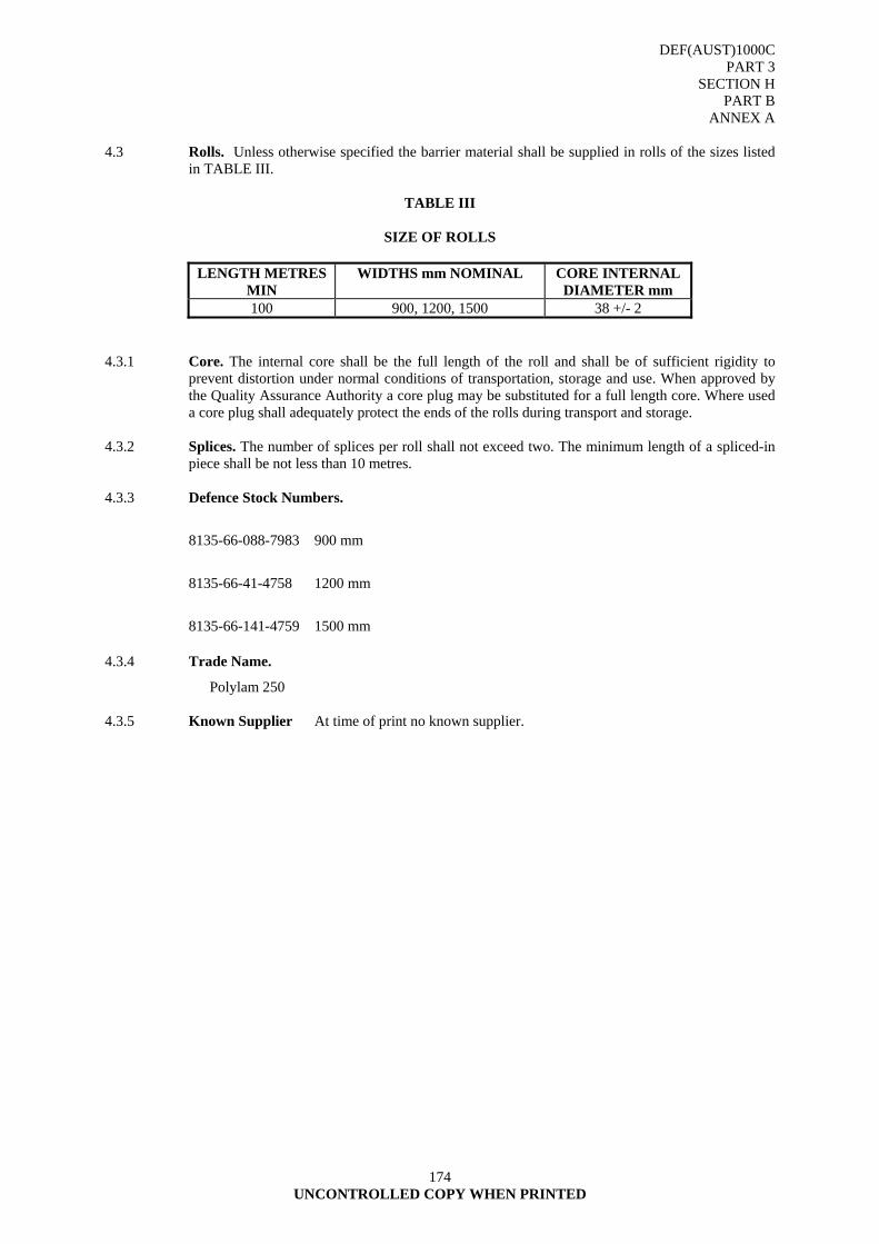
DEF(AUST)1000C PART 3
SECTION H PART B
ANNEX A
174 UNCONTROLLED COPY WHEN PRINTED
4.3 Rolls. Unless otherwise specified the barrier material shall be supplied in rolls of the sizes listed
in TABLE III.
TABLE III
SIZE OF ROLLS
LENGTH METRES MIN
WIDTHS mm NOMINAL CORE INTERNAL DIAMETER mm
100 900, 1200, 1500 38 +/- 2 4.3.1 Core. The internal core shall be the full length of the roll and shall be of sufficient rigidity to
prevent distortion under normal conditions of transportation, storage and use. When approved by the Quality Assurance Authority a core plug may be substituted for a full length core. Where used a core plug shall adequately protect the ends of the rolls during transport and storage.
4.3.2 Splices. The number of splices per roll shall not exceed two. The minimum length of a spliced-in
piece shall be not less than 10 metres. 4.3.3 Defence Stock Numbers.
8135-66-088-7983 900 mm
8135-66-41-4758 1200 mm
8135-66-141-4759 1500 mm
4.3.4 Trade Name.
Polylam 250
4.3.5 Known Supplier At time of print no known supplier.
DEF(AUST)1000C PART 3
SECTION I
175 UNCONTROLLED COPY WHEN PRINTED
SECTION I - PRIMARY WRAPPING MATERIALS SPECIFICATION
1. SCOPE
1.1 This section covers the requirements for primary wrapping materials for stores other than foodstuffs, which are covered by Australian Defence Forces Food Specification ADFFS 15-5-1.
1.2 Classification
1.2.1 The materials shall be supplied in the following classes and grades:
Class 1 Grade 1: Paper, wrapping, tissue, chemically treated, tarnish retardant
Class 1 Grade 2: Paper, wrapping, tissue, acid free
Class 1 Grade 3: Paper, wrapping, white fibre, chemically neutral
Class 1 Grade 4: Paper, wrapping, kraft, heavy duty, untreated
Class 1 Grade 5: Paper, wrapping, kraft, medium duty, untreated
Class 1 Grade 6: Paper, wrapping, kraft, light duty, untreated
Class 1 Grade 7: Paper, wrapping, waxed
Class 1 Grade 8: Paper, volatile corrosion inhibitor treated
Class 1 Grade 9: Paper, wrapping, vegetable parchment 2. REQUIREMENTS
2.1 General
2.1.1 the technical requirements and application for each class and grade of material are contained within this section as separate data sheets. These data sheets shall be read in conjunction with the other requirements of this section, and DEF(AUST)1000, PART 3, SECTION L.
2.2 Storage Stability
2.2.1 The Contractor shall provide evidence that the materials shall remain in a serviceable condition and shall comply with all physical property requirements of this section for a period of 12 months from the date of delivery providing the material remains unbroached within the original sealed packs and is stored at a temperature of not less than 5°C nor more than 32°C.
2.3 Acceptable Quality Levels
2.3.1 The Acceptable Quality Level (AQL) shall be as follows:
a. Special defects - 1.5 percent
b. Major defects - 2.5 percent
c. Minor defects - 10.0 percent
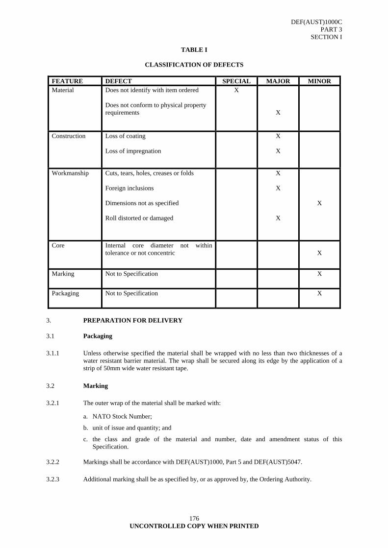
DEF(AUST)1000C PART 3
SECTION I
176 UNCONTROLLED COPY WHEN PRINTED
TABLE I
CLASSIFICATION OF DEFECTS
FEATURE DEFECT SPECIAL MAJOR MINOR Material Does not identify with item ordered
Does not conform to physical property requirements
X
X
Construction Loss of coating Loss of impregnation
X
X
Workmanship Cuts, tears, holes, creases or folds Foreign inclusions Dimensions not as specified Roll distorted or damaged
X
X
X
X
Core Internal core diameter not within tolerance or not concentric
X
Marking Not to Specification X
Packaging Not to Specification X
3. PREPARATION FOR DELIVERY
3.1 Packaging
3.1.1 Unless otherwise specified the material shall be wrapped with no less than two thicknesses of a water resistant barrier material. The wrap shall be secured along its edge by the application of a strip of 50mm wide water resistant tape.
3.2 Marking
3.2.1 The outer wrap of the material shall be marked with:
a. NATO Stock Number;
b. unit of issue and quantity; and
c. the class and grade of the material and number, date and amendment status of this Specification.
3.2.2 Markings shall be accordance with DEF(AUST)1000, Part 5 and DEF(AUST)5047.
3.2.3 Additional marking shall be as specified by, or as approved by, the Ordering Authority.
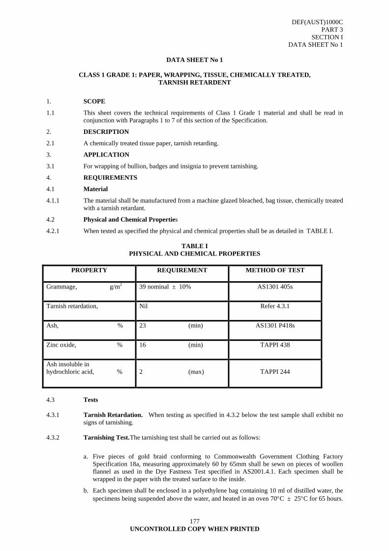
DEF(AUST)1000C PART 3
SECTION I DATA SHEET No 1
177 UNCONTROLLED COPY WHEN PRINTED
DATA SHEET No 1
CLASS 1 GRADE 1: PAPER, WRAPPING, TISSUE, CHEMICALLY TREATED,
TARNISH RETARDENT
1. SCOPE
1.1 This sheet covers the technical requirements of Class 1 Grade 1 material and shall be read in conjunction with Paragraphs 1 to 7 of this section of the Specification.
2. DESCRIPTION
2.1 A chemically treated tissue paper, tarnish retarding.
3. APPLICATION
3.1 For wrapping of bullion, badges and insignia to prevent tarnishing.
4. REQUIREMENTS
4.1 Material
4.1.1 The material shall be manufactured from a machine glazed bleached, bag tissue, chemically treated with a tarnish retardant.
4.2 Physical and Chemical Properties
4.2.1 When tested as specified the physical and chemical properties shall be as detailed in TABLE I.
TABLE I PHYSICAL AND CHEMICAL PROPERTIES
PROPERTY REQUIREMENT METHOD OF TEST
Grammage, g/m2 39 nominal ± 10% AS1301 405s
Tarnish retardation, Nil Refer 4.3.1
Ash, % 23 (min) AS1301 P418s
Zinc oxide, % 16 (min) TAPPI 438
Ash insoluble in hydrochloric acid, %
2 (max)
TAPPI 244
4.3 Tests 4.3.1 Tarnish Retardation. When testing as specified in 4.3.2 below the test sample shall exhibit no
signs of tarnishing. 4.3.2 Tarnishing Test. The tarnishing test shall be carried out as follows:
a. Five pieces of gold braid conforming to Commonwealth Government Clothing Factory Specification 18a, measuring approximately 60 by 65mm shall be sewn on pieces of woollen flannel as used in the Dye Fastness Test specified in AS2001.4.1. Each specimen shall be wrapped in the paper with the treated surface to the inside.
b. Each specimen shall be enclosed in a polyethylene bag containing 10 ml of distilled water, the specimens being suspended above the water, and heated in an oven 70°C ± 25°C for 65 hours.
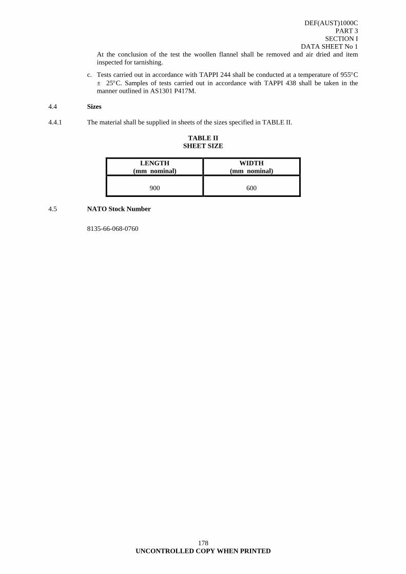
DEF(AUST)1000C PART 3
SECTION I DATA SHEET No 1
178 UNCONTROLLED COPY WHEN PRINTED
At the conclusion of the test the woollen flannel shall be removed and air dried and item inspected for tarnishing.
c. Tests carried out in accordance with TAPPI 244 shall be conducted at a temperature of 955°C ± 25°C. Samples of tests carried out in accordance with TAPPI 438 shall be taken in the manner outlined in AS1301 P417M.
4.4 Sizes 4.4.1 The material shall be supplied in sheets of the sizes specified in TABLE II.
TABLE II SHEET SIZE
LENGTH
(mm nominal) WIDTH
(mm nominal)
900
600
4.5 NATO Stock Number
8135-66-068-0760
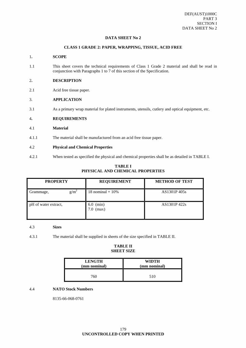
DEF(AUST)1000C PART 3
SECTION I DATA SHEET No 2
179 UNCONTROLLED COPY WHEN PRINTED
DATA SHEET No 2
CLASS 1 GRADE 2: PAPER, WRAPPING, TISSUE, ACID FREE
1. SCOPE 1.1 This sheet covers the technical requirements of Class 1 Grade 2 material and shall be read in
conjunction with Paragraphs 1 to 7 of this section of the Specification. 2. DESCRIPTION 2.1 Acid free tissue paper. 3. APPLICATION 3.1 As a primary wrap material for plated instruments, utensils, cutlery and optical equipment, etc. 4. REQUIREMENTS 4.1 Material 4.1.1 The material shall be manufactured from an acid free tissue paper. 4.2 Physical and Chemical Properties 4.2.1 When tested as specified the physical and chemical properties shall be as detailed in TABLE I.
TABLE I PHYSICAL AND CHEMICAL PROPERTIES
PROPERTY REQUIREMENT METHOD OF TEST
Grammage, g/m2 18 nominal + 10% AS1301P 405s
pH of water extract, 6.0 (min) 7.0 (max)
AS1301P 422s
4.3 Sizes 4.3.1 The material shall be supplied in sheets of the size specified in TABLE II.
TABLE II SHEET SIZE
LENGTH
(mm nominal) WIDTH
(mm nominal)
760
510
4.4 NATO Stock Numbers 8135-66-068-0761
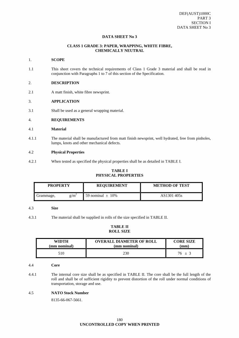
DEF(AUST)1000C PART 3
SECTION I DATA SHEET No 3
180 UNCONTROLLED COPY WHEN PRINTED
DATA SHEET No 3
CLASS 1 GRADE 3: PAPER, WRAPPING, WHITE FIBRE,
CHEMICALLY NEUTRAL 1. SCOPE 1.1 This sheet covers the technical requirements of Class 1 Grade 3 material and shall be read in
conjunction with Paragraphs 1 to 7 of this section of the Specification. 2. DESCRIPTION 2.1 A matt finish, white fibre newsprint. 3. APPLICATION 3.1 Shall be used as a general wrapping material. 4. REQUIREMENTS 4.1 Material 4.1.1 The material shall be manufactured from matt finish newsprint, well hydrated, free from pinholes,
lumps, knots and other mechanical defects. 4.2 Physical Properties 4.2.1 When tested as specified the physical properties shall be as detailed in TABLE I.
TABLE I PHYSICAL PROPERTIES
PROPERTY REQUIREMENT METHOD OF TEST
Grammage, g/m2 59 nominal ± 10% AS1301 405s
4.3 Size 4.3.1 The material shall be supplied in rolls of the size specified in TABLE II.
TABLE II ROLL SIZE
WIDTH
(mm nominal) OVERALL DIAMETER OF ROLL
(mm nominal) CORE SIZE
(mm)
510 230 76 ± 3
4.4 Core 4.4.1 The internal core size shall be as specified in TABLE II. The core shall be the full length of the
roll and shall be of sufficient rigidity to prevent distortion of the roll under normal conditions of transportation, storage and use.
4.5 NATO Stock Number
8135-66-067-5661.

DEF(AUST)1000C PART 3
SECTION I DATA SHEET No 4
181 UNCONTROLLED COPY WHEN PRINTED
DATA SHEET No 4
CLASS 1 GRADE 4: PAPER, WRAPPING, KRAFT, HEAVY DUTY, UNTREATED
1. SCOPE 1.1 This sheet cover the technical requirements of Class 1 Grade 4 material and shall be read in
conjunction with Paragraphs 1 to 7 of this section of the Specification. 2. DESCRIPTION 2.1 A machine finished, unbleached, untreated, machine glazed, brown kraft paper. 3. APPLICATION 3.1 A general purpose, heavy duty wrapping paper used for packages, where a high strength material
is required. 4. REQUIREMENTS 4.1 Materials 4.1.1 The material shall be capable of being wax coated with dip sealing compounds or treated with
fungicidal agents. 4.2 Physical and Chemical Properties. 4.2.1 When tested as specified the physical and chemical properties shall be as detailed in TABLE I.
TABLE I PHYSICAL AND CHEMICAL PROPERTIES
PROPERTY REQUIREMENT METHOD OF TEST
Grammage, g/m2 85 nominal ± 10% AS1301 405s
pH of water extract, 5.5 (min) 8.8 (max)
AS1301 422Ss
Burst strength, kPa 250 (min) AS1301 P403s
Chlorides, % NaCl 0.05 (max) ANNEX A
Sulphates, % Na2SO4 0.25 (max) ANNEX B
4.3 Condition Prior to Testing. 4.3.1 The test specimens shall be conditioned in accordance with the requirements of AS1301 P414m. 4.4 Methods for Determination of Chloride and Sulphate Content. 4.4.1 Refer Annexes A and B. 4.5 Sizes

DEF(AUST)1000C PART 3
SECTION I DATA SHEET No 4
182 UNCONTROLLED COPY WHEN PRINTED
4.5.1 The material shall be supplied in rolls of the size specified in TABLE II.
TABLE II ROLL SIZE
WIDTH
(mm nominal) OVERALL DIAMETER OF ROLL
(mm nominal) CORE SIZE
(mm)
915
230
76 ± 3
4.6 Core 4.6.1 The internal core size shall be as specified in TABLE II. The core shall be the full length of the
roll and shall be of sufficient rigidity to prevent distortion of the roll under normal conditions of transportation, storage and use.
4.7 NATO Stock Number
8135-66-062-1743.
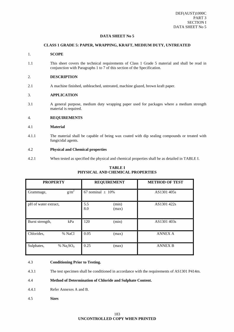
DEF(AUST)1000C PART 3
SECTION I DATA SHEET No 5
183 UNCONTROLLED COPY WHEN PRINTED
DATA SHEET No 5
CLASS 1 GRADE 5: PAPER, WRAPPING, KRAFT, MEDIUM DUTY, UNTREATED
1. SCOPE 1.1 This sheet covers the technical requirements of Class 1 Grade 5 material and shall be read in
conjunction with Paragraphs 1 to 7 of this section of the Specification. 2. DESCRIPTION 2.1 A machine finished, unbleached, untreated, machine glazed, brown kraft paper. 3. APPLICATION 3.1 A general purpose, medium duty wrapping paper used for packages where a medium strength
material is required. 4. REQUIREMENTS 4.1 Material 4.1.1 The material shall be capable of being wax coated with dip sealing compounds or treated with
fungicidal agents. 4.2 Physical and Chemical properties 4.2.1 When tested as specified the physical and chemical properties shall be as detailed in TABLE I.
TABLE I PHYSICAL AND CHEMICAL PROPERTIES
PROPERTY REQUIREMENT METHOD OF TEST
Grammage, g/m2 67 nominal ± 10% AS1301 405s
pH of water extract, 5.5 (min) 8.0 (max)
AS1301 422s
Burst strength, kPa 120 (min) AS1301 403s
Chlorides, % NaCl 0.05 (max) ANNEX A
Sulphates, % Na2SO4 0.25 (max) ANNEX B
4.3 Conditioning Prior to Testing. 4.3.1 The test specimen shall be conditioned in accordance with the requirements of AS1301 P414m. 4.4 Method of Determination of Chloride and Sulphate Content. 4.4.1 Refer Annexes A and B. 4.5 Sizes
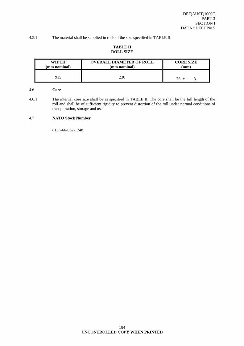
DEF(AUST)1000C PART 3
SECTION I DATA SHEET No 5
184 UNCONTROLLED COPY WHEN PRINTED
4.5.1 The material shall be supplied in rolls of the size specified in TABLE II.
TABLE II ROLL SIZE
WIDTH
(mm nominal) OVERALL DIAMETER OF ROLL
(mm nominal) CORE SIZE
(mm)
915
230
76 ± 3 4.6 Core 4.6.1 The internal core size shall be as specified in TABLE II. The core shall be the full length of the
roll and shall be of sufficient rigidity to prevent distortion of the roll under normal conditions of transportation, storage and use.
4.7 NATO Stock Number
8135-66-062-1748.
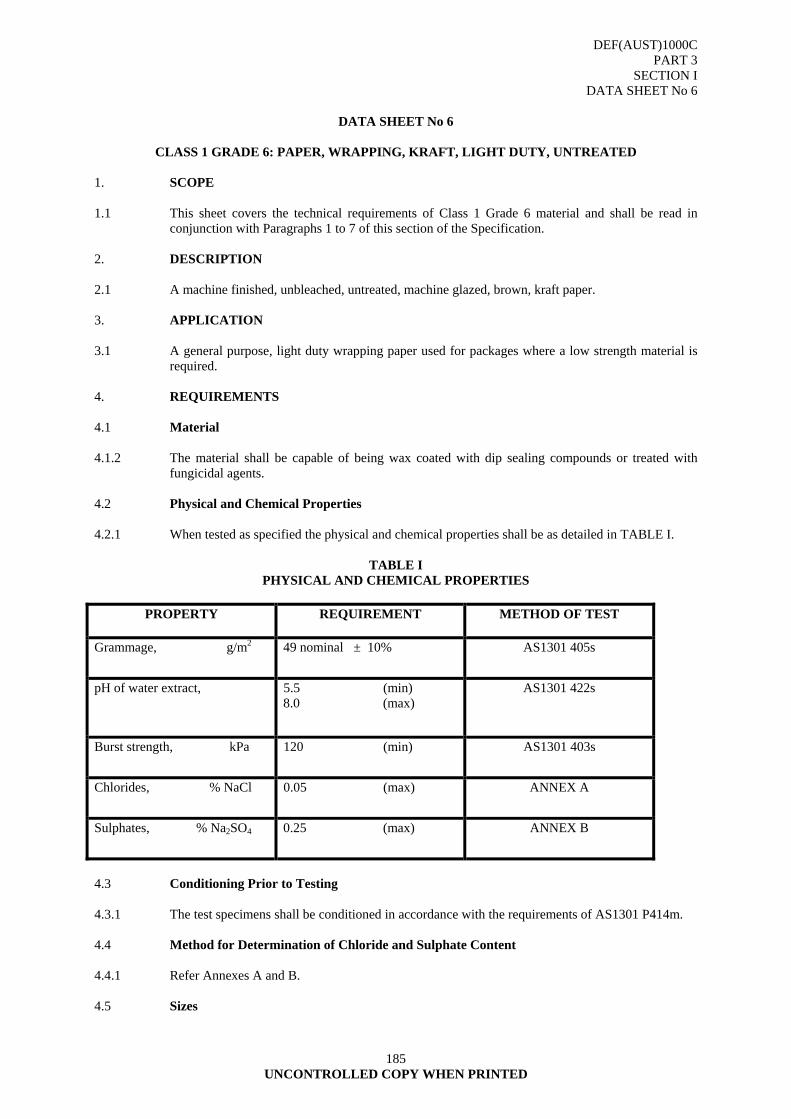
DEF(AUST)1000C PART 3
SECTION I DATA SHEET No 6
185 UNCONTROLLED COPY WHEN PRINTED
DATA SHEET No 6
CLASS 1 GRADE 6: PAPER, WRAPPING, KRAFT, LIGHT DUTY, UNTREATED
1. SCOPE 1.1 This sheet covers the technical requirements of Class 1 Grade 6 material and shall be read in
conjunction with Paragraphs 1 to 7 of this section of the Specification. 2. DESCRIPTION 2.1 A machine finished, unbleached, untreated, machine glazed, brown, kraft paper. 3. APPLICATION 3.1 A general purpose, light duty wrapping paper used for packages where a low strength material is
required. 4. REQUIREMENTS 4.1 Material 4.1.2 The material shall be capable of being wax coated with dip sealing compounds or treated with
fungicidal agents. 4.2 Physical and Chemical Properties 4.2.1 When tested as specified the physical and chemical properties shall be as detailed in TABLE I.
TABLE I PHYSICAL AND CHEMICAL PROPERTIES
PROPERTY REQUIREMENT METHOD OF TEST
Grammage, g/m2 49 nominal ± 10% AS1301 405s
pH of water extract, 5.5 (min) 8.0 (max)
AS1301 422s
Burst strength, kPa 120 (min) AS1301 403s
Chlorides, % NaCl 0.05 (max) ANNEX A
Sulphates, % Na2SO4 0.25 (max) ANNEX B
4.3 Conditioning Prior to Testing 4.3.1 The test specimens shall be conditioned in accordance with the requirements of AS1301 P414m. 4.4 Method for Determination of Chloride and Sulphate Content 4.4.1 Refer Annexes A and B. 4.5 Sizes

DEF(AUST)1000C PART 3
SECTION I DATA SHEET No 6
186 UNCONTROLLED COPY WHEN PRINTED
4.5.1 The materials shall be supplied in rolls in the size specified in TABLE II.
TABLE II ROLL SIZE
WIDTH
(mm nominal) OVERALL DIAMETER OF ROLL
(mm nominal) CORE SIZE
(mm)
915
230
76 ± 3
4.6 Core 4.6.1 The internal core size shall be as specified in TABLE II. The core shall be the full length of the
roll and shall be of sufficient rigidity to prevent distortion of the roll under normal conditions of transportation, storage and use.
4.7 NATO Stock Number
8135-66-062-1749.
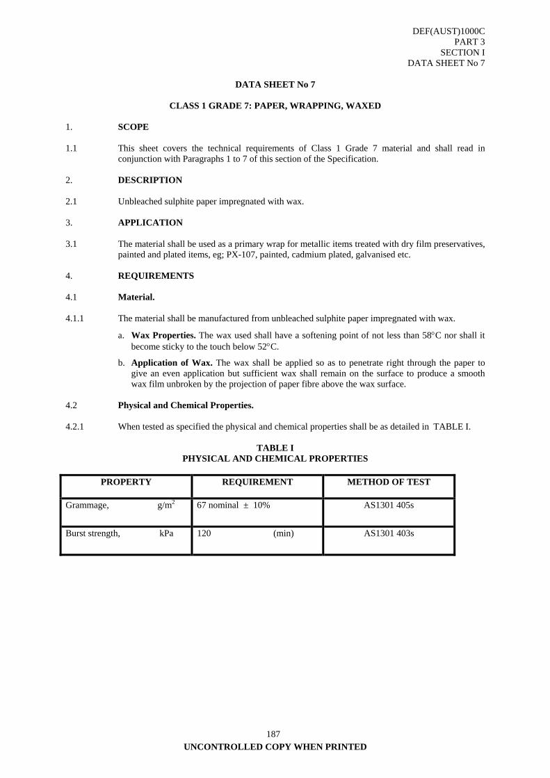
DEF(AUST)1000C PART 3
SECTION I DATA SHEET No 7
UNCONTROLLED COPY WHEN PRINTED
187
DATA SHEET No 7
CLASS 1 GRADE 7: PAPER, WRAPPING, WAXED
1. SCOPE 1.1 This sheet covers the technical requirements of Class 1 Grade 7 material and shall read in
conjunction with Paragraphs 1 to 7 of this section of the Specification. 2. DESCRIPTION 2.1 Unbleached sulphite paper impregnated with wax. 3. APPLICATION 3.1 The material shall be used as a primary wrap for metallic items treated with dry film preservatives,
painted and plated items, eg; PX-107, painted, cadmium plated, galvanised etc. 4. REQUIREMENTS 4.1 Material. 4.1.1 The material shall be manufactured from unbleached sulphite paper impregnated with wax.
a. Wax Properties. The wax used shall have a softening point of not less than 58°C nor shall it become sticky to the touch below 52°C.
b. Application of Wax. The wax shall be applied so as to penetrate right through the paper to give an even application but sufficient wax shall remain on the surface to produce a smooth wax film unbroken by the projection of paper fibre above the wax surface.
4.2 Physical and Chemical Properties. 4.2.1 When tested as specified the physical and chemical properties shall be as detailed in TABLE I.
TABLE I PHYSICAL AND CHEMICAL PROPERTIES
PROPERTY REQUIREMENT METHOD OF TEST
Grammage, g/m2 67 nominal ± 10% AS1301 405s
Burst strength, kPa 120 (min) AS1301 403s
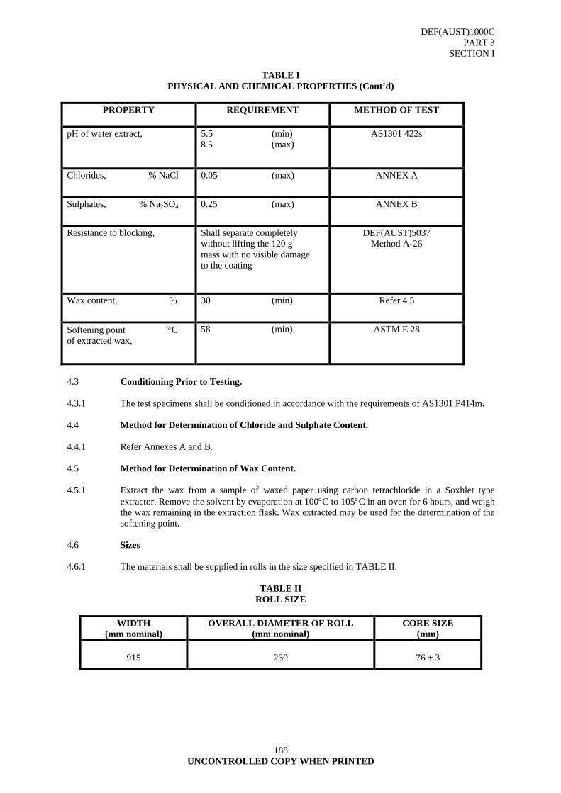
DEF(AUST)1000C PART 3
SECTION I
188 UNCONTROLLED COPY WHEN PRINTED
TABLE I PHYSICAL AND CHEMICAL PROPERTIES (Cont’d)
PROPERTY REQUIREMENT METHOD OF TEST
pH of water extract, 5.5 (min)
8.5 (max) AS1301 422s
Chlorides, % NaCl 0.05 (max) ANNEX A
Sulphates, % Na2SO4 0.25 (max) ANNEX B
Resistance to blocking, Shall separate completely without lifting the 120 g mass with no visible damage to the coating
DEF(AUST)5037 Method A-26
Wax content, % 30 (min) Refer 4.5
Softening point °C of extracted wax,
58 (min) ASTM E 28
4.3 Conditioning Prior to Testing. 4.3.1 The test specimens shall be conditioned in accordance with the requirements of AS1301 P414m. 4.4 Method for Determination of Chloride and Sulphate Content. 4.4.1 Refer Annexes A and B. 4.5 Method for Determination of Wax Content. 4.5.1 Extract the wax from a sample of waxed paper using carbon tetrachloride in a Soxhlet type
extractor. Remove the solvent by evaporation at 100°C to 105°C in an oven for 6 hours, and weigh the wax remaining in the extraction flask. Wax extracted may be used for the determination of the softening point.
4.6 Sizes 4.6.1 The materials shall be supplied in rolls in the size specified in TABLE II.
TABLE II ROLL SIZE
WIDTH
(mm nominal) OVERALL DIAMETER OF ROLL
(mm nominal) CORE SIZE
(mm)
915
230
76 ± 3

DEF(AUST)1000C PART 3
SECTION I
189 UNCONTROLLED COPY WHEN PRINTED
4.7 Core 4.7.1 The internal core size shall be as specified in TABLE II. The core shall be the full length of the
roll and shall be of sufficient rigidity to prevent distortion of the roll under normal conditions of transportation, storage and use.
4.8 NATO Stock Number
8135-66-068-0762.
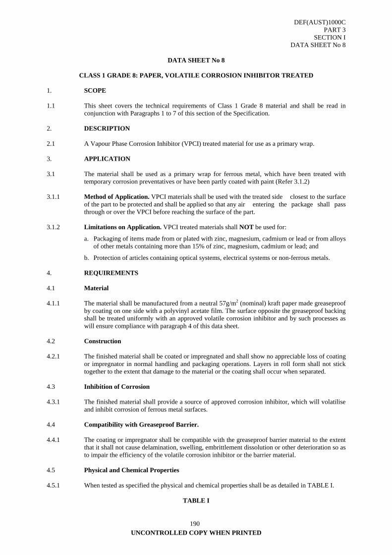
DEF(AUST)1000C PART 3
SECTION I DATA SHEET No 8
UNCONTROLLED COPY WHEN PRINTED
190
DATA SHEET No 8
CLASS 1 GRADE 8: PAPER, VOLATILE CORROSION INHIBITOR TREATED
1. SCOPE 1.1 This sheet covers the technical requirements of Class 1 Grade 8 material and shall be read in
conjunction with Paragraphs 1 to 7 of this section of the Specification. 2. DESCRIPTION 2.1 A Vapour Phase Corrosion Inhibitor (VPCI) treated material for use as a primary wrap. 3. APPLICATION 3.1 The material shall be used as a primary wrap for ferrous metal, which have been treated with
temporary corrosion preventatives or have been partly coated with paint (Refer 3.1.2) 3.1.1 Method of Application. VPCI materials shall be used with the treated side closest to the surface
of the part to be protected and shall be applied so that any air entering the package shall pass through or over the VPCI before reaching the surface of the part.
3.1.2 Limitations on Application. VPCI treated materials shall NOT be used for:
a. Packaging of items made from or plated with zinc, magnesium, cadmium or lead or from alloys of other metals containing more than 15% of zinc, magnesium, cadmium or lead; and
b. Protection of articles containing optical systems, electrical systems or non-ferrous metals. 4. REQUIREMENTS 4.1 Material 4.1.1 The material shall be manufactured from a neutral 57g/m2 (nominal) kraft paper made greaseproof
by coating on one side with a polyvinyl acetate film. The surface opposite the greaseproof backing shall be treated uniformly with an approved volatile corrosion inhibitor and by such processes as will ensure compliance with paragraph 4 of this data sheet.
4.2 Construction 4.2.1 The finished material shall be coated or impregnated and shall show no appreciable loss of coating
or impregnator in normal handling and packaging operations. Layers in roll form shall not stick together to the extent that damage to the material or the coating shall occur when separated.
4.3 Inhibition of Corrosion 4.3.1 The finished material shall provide a source of approved corrosion inhibitor, which will volatilise
and inhibit corrosion of ferrous metal surfaces. 4.4 Compatibility with Greaseproof Barrier. 4.4.1 The coating or impregnator shall be compatible with the greaseproof barrier material to the extent
that it shall not cause delamination, swelling, embrittlement dissolution or other deterioration so as to impair the efficiency of the volatile corrosion inhibitor or the barrier material.
4.5 Physical and Chemical Properties 4.5.1 When tested as specified the physical and chemical properties shall be as detailed in TABLE I.
TABLE I
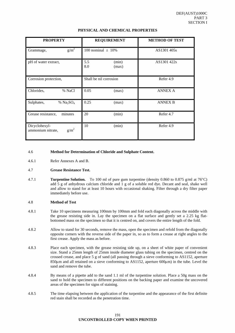
DEF(AUST)1000C PART 3
SECTION I
191 UNCONTROLLED COPY WHEN PRINTED
PHYSICAL AND CHEMICAL PROPERTIES
PROPERTY REQUIREMENT METHOD OF TEST
Grammage, g/m2 100 nominal ± 10% AS1301 405s
pH of water extract, 5.5 (min) 8.0 (max)
AS1301 422s
Corrosion protection, Shall be nil corrosion Refer 4.9
Chlorides, % NaCl 0.05 (max) ANNEX A
Sulphates, % Na2SO4 0.25 (max) ANNEX B
Grease resistance, minutes 20 (min) Refer 4.7
Dicyclohexyl- ammonium nitrate, g/m2
10 (min) Refer 4.9
4.6 Method for Determination of Chloride and Sulphate Content. 4.6.1 Refer Annexes A and B. 4.7 Grease Resistance Test. 4.7.1 Turpentine Solution. To 100 ml of pure gum turpentine (density 0.860 to 0.875 g/ml at 76°C)
add 5 g of anhydrous calcium chloride and 1 g of a soluble red dye. Decant and seal, shake well and allow to stand for at least 10 hours with occasional shaking. Filter through a dry filter paper immediately before use.
4.8 Method of Test 4.8.1 Take 10 specimens measuring 100mm by 100mm and fold each diagonally across the middle with
the grease resisting side in. Lay the specimen on a flat surface and gently set a 2.25 kg flat-bottomed mass on the specimen so that it is centred on, and covers the entire length of the fold.
4.8.2 Allow to stand for 30 seconds, remove the mass, open the specimen and refold from the diagonally
opposite corners with the reverse side of the paper in, so as to form a crease at right angles to the first crease. Apply the mass as before.
4.8.3 Place each specimen, with the grease resisting side up, on a sheet of white paper of convenient
size. Stand a 25mm length of 25mm inside diameter glass tubing on the specimen, centred on the crossed crease, and place 5 g of sand (all passing through a sieve conforming to AS1152, aperture 850μm and all retained on a sieve conforming to AS1152, aperture 600μm) in the tube. Level the sand and remove the tube.
4.8.4 By means of a pipette add to the sand 1.1 ml of the turpentine solution. Place a 50g mass on the
sand to hold the specimen to different positions on the backing paper and examine the uncovered areas of the specimen for signs of staining.
4.8.5 The time elapsing between the application of the turpentine and the appearance of the first definite
red stain shall be recorded as the penetration time.
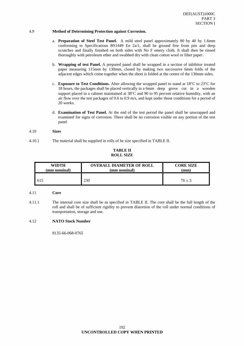
DEF(AUST)1000C PART 3
SECTION I
192 UNCONTROLLED COPY WHEN PRINTED
4.9 Method of Determining Protection against Corrosion.
a. Preparation of Steel Test Panel. A mild steel panel approximately 80 by 40 by 1.6mm conforming to Specifications BS1449 En 2a/1, shall be ground free from pits and deep scratches and finally finished on both sides with No F emery cloth. It shall then be rinsed thoroughly with petroleum ether and swabbed dry with clean cotton wool or filter paper.
b. Wrapping of test Panel. A prepared panel shall be wrapped in a section of inhibitor treated
paper measuring 115mm by 130mm, closed by making two successive 6mm folds of the adjacent edges which come together when the sheet is folded at the centre of the 130mm sides.
c. Exposure to Test Conditions. After allowing the wrapped panel to stand at 18°C to 23°C for
18 hours, the packages shall be placed vertically in a 6mm deep grove cut in a wooden support placed in a cabinet maintained at 38°C and 90 to 95 percent relative humidity, with an air flow over the test packages of 0.6 to 0.9 m/s, and kept under those conditions for a period of 20 weeks.
d. Examination of Test Panel. At the end of the test period the panel shall be unwrapped and
examined for signs of corrosion. There shall be no corrosion visible on any portion of the test panel
4.10 Sizes 4.10.1 The material shall be supplied in rolls of he size specified in TABLE II.
TABLE II ROLL SIZE
WIDTH
(mm nominal) OVERALL DIAMETER OF ROLL
(mm nominal) CORE SIZE
(mm) 615
230
76 ± 3
4.11 Core 4.11.1 The internal core size shall be as specified in TABLE II. The core shall be the full length of the
roll and shall be of sufficient rigidity to prevent distortion of the roll under normal conditions of transportation, storage and use.
4.12 NATO Stock Number
8135-66-068-0765
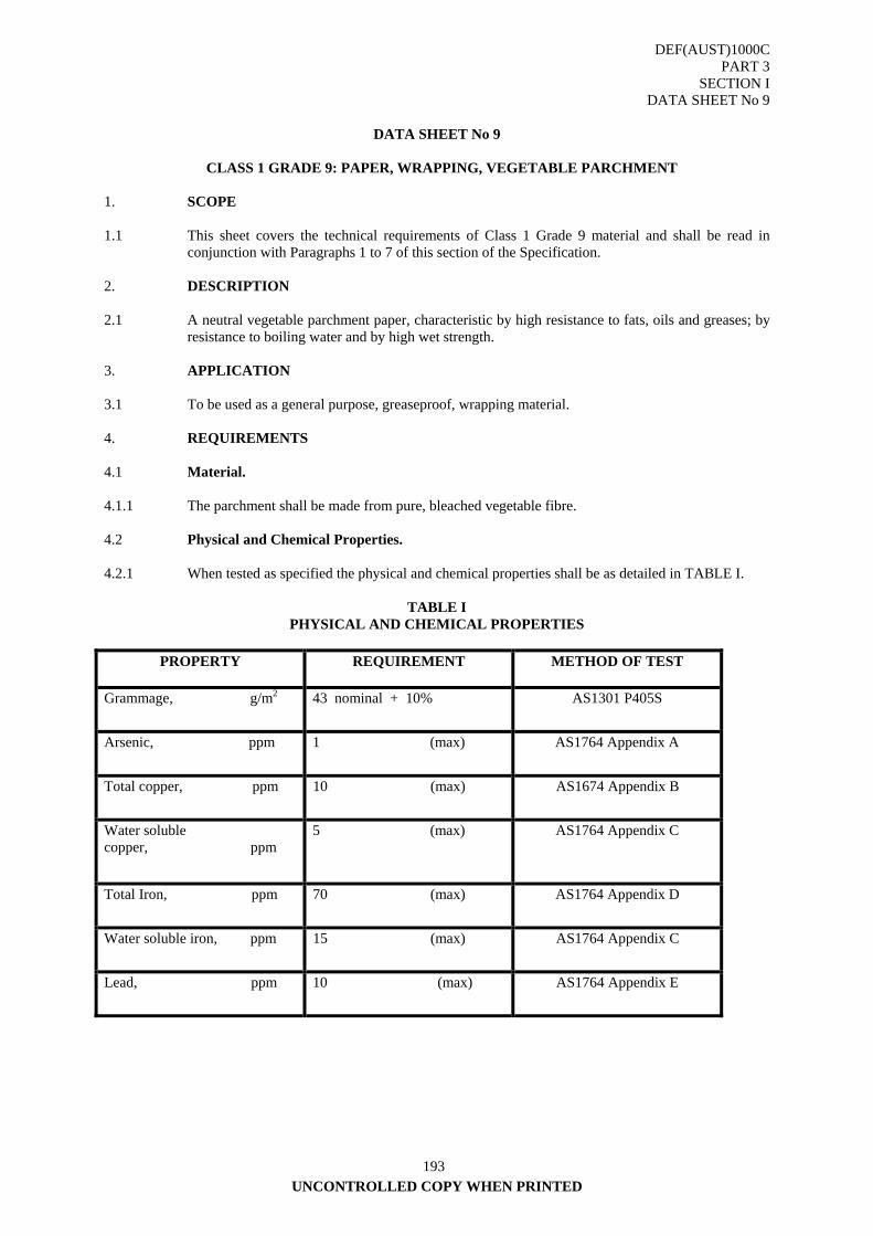
DEF(AUST)1000C PART 3
SECTION I DATA SHEET No 9
UNCONTROLLED COPY WHEN PRINTED
193
DATA SHEET No 9
CLASS 1 GRADE 9: PAPER, WRAPPING, VEGETABLE PARCHMENT
1. SCOPE 1.1 This sheet covers the technical requirements of Class 1 Grade 9 material and shall be read in
conjunction with Paragraphs 1 to 7 of this section of the Specification. 2. DESCRIPTION 2.1 A neutral vegetable parchment paper, characteristic by high resistance to fats, oils and greases; by
resistance to boiling water and by high wet strength. 3. APPLICATION 3.1 To be used as a general purpose, greaseproof, wrapping material. 4. REQUIREMENTS 4.1 Material. 4.1.1 The parchment shall be made from pure, bleached vegetable fibre. 4.2 Physical and Chemical Properties. 4.2.1 When tested as specified the physical and chemical properties shall be as detailed in TABLE I.
TABLE I PHYSICAL AND CHEMICAL PROPERTIES
PROPERTY REQUIREMENT METHOD OF TEST
Grammage, g/m2 43 nominal + 10% AS1301 P405S
Arsenic, ppm 1 (max) AS1764 Appendix A
Total copper, ppm 10 (max) AS1674 Appendix B
Water soluble copper, ppm
5 (max) AS1764 Appendix C
Total Iron, ppm 70 (max) AS1764 Appendix D
Water soluble iron, ppm 15 (max) AS1764 Appendix C
Lead, ppm 10 (max) AS1764 Appendix E
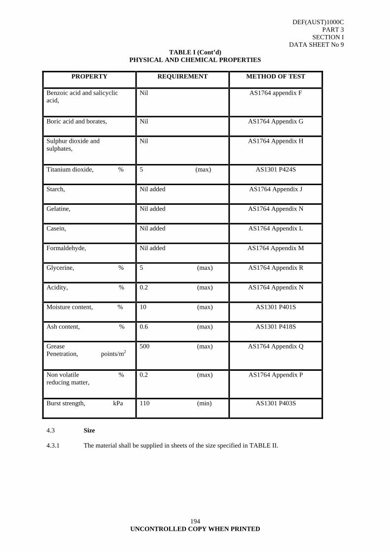
DEF(AUST)1000C PART 3
SECTION I DATA SHEET No 9
194 UNCONTROLLED COPY WHEN PRINTED
TABLE I (Cont’d) PHYSICAL AND CHEMICAL PROPERTIES
PROPERTY REQUIREMENT METHOD OF TEST
Benzoic acid and salicyclic acid,
Nil AS1764 appendix F
Boric acid and borates, Nil AS1764 Appendix G
Sulphur dioxide and sulphates,
Nil AS1764 Appendix H
Titanium dioxide, % 5 (max) AS1301 P424S
Starch, Nil added AS1764 Appendix J
Gelatine, Nil added AS1764 Appendix N
Casein, Nil added AS1764 Appendix L
Formaldehyde, Nil added AS1764 Appendix M
Glycerine, % 5 (max) AS1764 Appendix R
Acidity, % 0.2 (max) AS1764 Appendix N
Moisture content, % 10 (max) AS1301 P401S
Ash content, % 0.6 (max) AS1301 P418S
Grease Penetration, points/m2
500 (max) AS1764 Appendix Q
Non volatile % reducing matter,
0.2 (max) AS1764 Appendix P
Burst strength, kPa 110 (min) AS1301 P403S
4.3 Size 4.3.1 The material shall be supplied in sheets of the size specified in TABLE II.
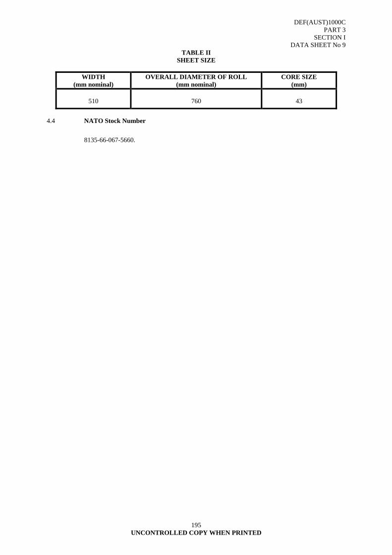
DEF(AUST)1000C PART 3
SECTION I DATA SHEET No 9
195 UNCONTROLLED COPY WHEN PRINTED
TABLE II SHEET SIZE
WIDTH
(mm nominal) OVERALL DIAMETER OF ROLL
(mm nominal) CORE SIZE
(mm)
510
760
43
4.4 NATO Stock Number
8135-66-067-5660.
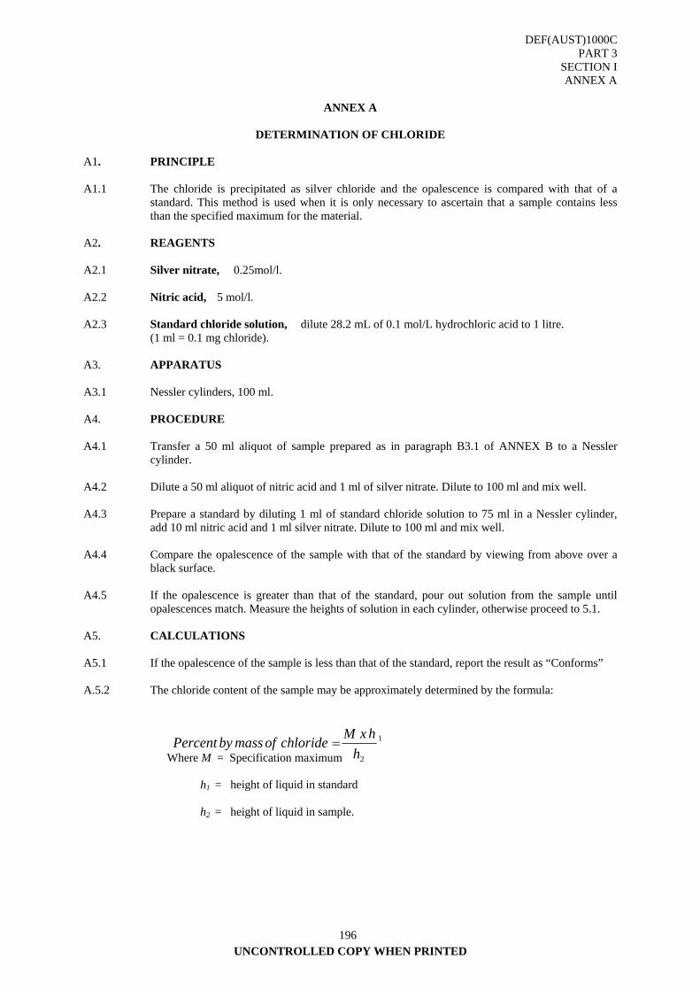
DEF(AUST)1000C PART 3
SECTION I ANNEX A
UNCONTROLLED COPY WHEN PRINTED
196
ANNEX A
DETERMINATION OF CHLORIDE
A1. PRINCIPLE A1.1 The chloride is precipitated as silver chloride and the opalescence is compared with that of a
standard. This method is used when it is only necessary to ascertain that a sample contains less than the specified maximum for the material.
A2. REAGENTS A2.1 Silver nitrate, 0.25mol/l. A2.2 Nitric acid, 5 mol/l. A2.3 Standard chloride solution, dilute 28.2 mL of 0.1 mol/L hydrochloric acid to 1 litre. (1 ml = 0.1 mg chloride). A3. APPARATUS A3.1 Nessler cylinders, 100 ml. A4. PROCEDURE A4.1 Transfer a 50 ml aliquot of sample prepared as in paragraph B3.1 of ANNEX B to a Nessler
cylinder. A4.2 Dilute a 50 ml aliquot of nitric acid and 1 ml of silver nitrate. Dilute to 100 ml and mix well. A4.3 Prepare a standard by diluting 1 ml of standard chloride solution to 75 ml in a Nessler cylinder,
add 10 ml nitric acid and 1 ml silver nitrate. Dilute to 100 ml and mix well. A4.4 Compare the opalescence of the sample with that of the standard by viewing from above over a
black surface. A4.5 If the opalescence is greater than that of the standard, pour out solution from the sample until
opalescences match. Measure the heights of solution in each cylinder, otherwise proceed to 5.1. A5. CALCULATIONS A5.1 If the opalescence of the sample is less than that of the standard, report the result as “Conforms” A.5.2 The chloride content of the sample may be approximately determined by the formula: Where M = Specification maximum h1 = height of liquid in standard h2 = height of liquid in sample.
1
2hhxMchlorideofmassbyPercent =
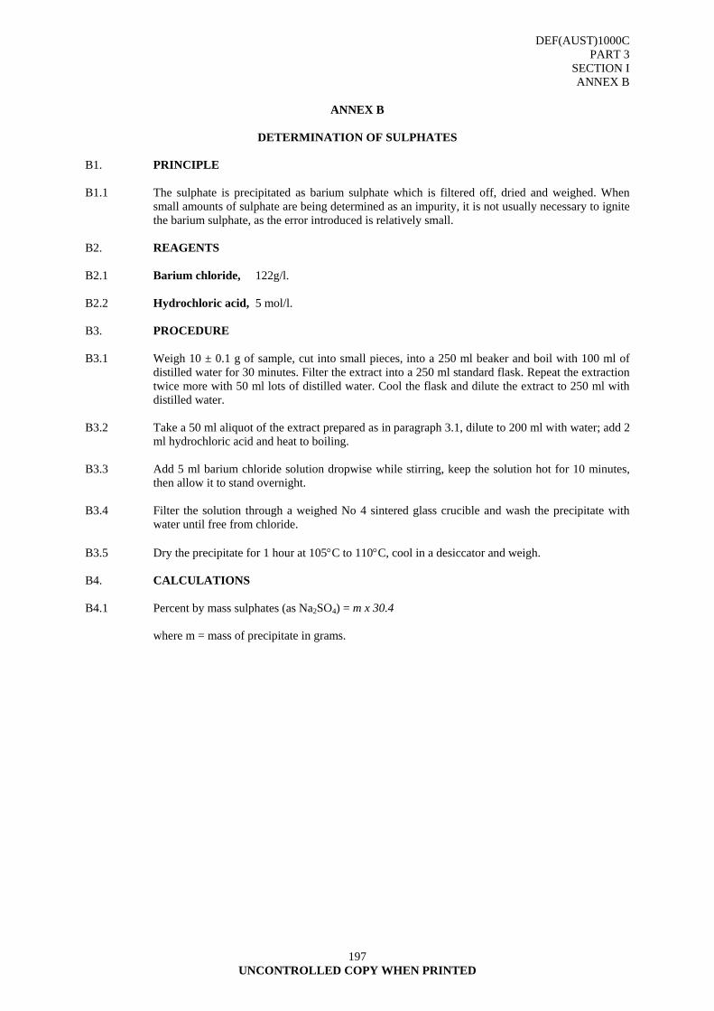
DEF(AUST)1000C PART 3
SECTION I ANNEX B
197 UNCONTROLLED COPY WHEN PRINTED
ANNEX B
DETERMINATION OF SULPHATES
B1. PRINCIPLE B1.1 The sulphate is precipitated as barium sulphate which is filtered off, dried and weighed. When
small amounts of sulphate are being determined as an impurity, it is not usually necessary to ignite the barium sulphate, as the error introduced is relatively small.
B2. REAGENTS B2.1 Barium chloride, 122g/l. B2.2 Hydrochloric acid, 5 mol/l. B3. PROCEDURE B3.1 Weigh 10 ± 0.1 g of sample, cut into small pieces, into a 250 ml beaker and boil with 100 ml of
distilled water for 30 minutes. Filter the extract into a 250 ml standard flask. Repeat the extraction twice more with 50 ml lots of distilled water. Cool the flask and dilute the extract to 250 ml with distilled water.
B3.2 Take a 50 ml aliquot of the extract prepared as in paragraph 3.1, dilute to 200 ml with water; add 2
ml hydrochloric acid and heat to boiling. B3.3 Add 5 ml barium chloride solution dropwise while stirring, keep the solution hot for 10 minutes,
then allow it to stand overnight. B3.4 Filter the solution through a weighed No 4 sintered glass crucible and wash the precipitate with
water until free from chloride. B3.5 Dry the precipitate for 1 hour at 105°C to 110°C, cool in a desiccator and weigh. B4. CALCULATIONS B4.1 Percent by mass sulphates (as Na2SO4) = m x 30.4 where m = mass of precipitate in grams.
DEF(AUST)1000C PART 3
SECTION J
198 UNCONTROLLED COPY WHEN PRINTED
SECTION J - TECHNICAL REQUIREMENTS FOR PROTECTION DURING DISTRIBUTION - CONTAINERS
1. GENERAL
1.1 The principal materials used in the construction of containers are:
Bag and Sacks
Fibreboard
Wood
Metal
Plastics
Glass
1.2 The proper closure of a container is an important factor. The closure is usually an integral part of a container made from metal, plastics, or glass. Although this is also true sometimes of wooden containers, and more rarely fibreboard containers, the most common methods of closure employed for these are separately applied. Sometimes the closure has to be reinforced.
1.3 It is sometimes necessary to line a container, either as an integral part of the container or in the form of a loose liner, to improve some particular property. It may be to make the container suitably resistant to the contents (e.g. metal containers may be lined with plastics materials resistant to acids), or, the most common example of lining, to provide a waterproof liner for a fibreboard or wooden container to prevent ingress of water. Loose bag liners should be used wherever practicable. Fitted waterproof linings should only be used for large containers and/or where the method of location necessarily employed would constitute a hazard for a loose liner.
1.4 Some containers incorporate means for their handling, but, in general, these are only adequate for packages of low gross mass. For heavier loads handling aids are often required to be built into the container structure.
1.5 Containers must afford protection to the contents from packing to delivery in the face of adverse field conditions. The minimum number of container sizes are used to simplify procurement and supply.
2. DEFINITION
2.1 A shipping container is a container, which is sufficiently strong to be shipped safely without further packaging, either as a primary pack or as an outer container, which encloses one or more items during storage or shipment.
3. SELECTION
3.1 Container Functions
3.1.1 The primary design consideration of an exterior container is the protection of the contents while providing ease of handling, sometimes by consolidating a number of this item into a single unit. Certain features of containers require attention regardless of the characteristics of their contents. The location of the centre of gravity of container is important in handling and stacking. Strength considerations require analysis of stacking requirements, lifting and handling problems, internal air pressure, mass of contents and protection from drops.
DEF(AUST)1000C PART 3
SECTION J
199 UNCONTROLLED COPY WHEN PRINTED
3.2 Item Characteristics
3.2.1 In selecting containers, the following considerations are relevant:
a. its fragility;
b. its hazardous nature;
c. any need for use in minimum reaction time;
d. its repairability or recoverability;
e. its cost;
f. the requirement for high reliability;
g. economy of use in relation to an alternative; and
h. its compatibility with an existing container.
3.2.2 Physical characteristics of size, fragility level, mass and mass distribution of an item determine the container size, type and therefore cost. Item mass influences:
a. size and strength of the container's structural members;
b. type and capacity of blocking and vibrations systems;
c. transportation costs; and
d. the manual and mechanical handling requirements.
3.3 Type of Load
3.3.1 The type of load (the ability of an item to add strength or cause damage to the container) is important in determining container selection. Internal and external forces, such as the force of the item on the container, the pressure of tight shipping bands and the additional loads caused by handling and transportation, decree that containers must be selected which will not dent or crush, thereby damaging the packaged item (Refer ANNEX B).
4. EXTERIOR CONTAINERS
4.1 Rationalisation
4.1.1 Containers should be durable and consistent with distribution flow and environmental conditions. The minimum number of different containers necessary to house the complete item should be used, consistent with safety regulations. The same basic design and construction should be used for containers holding like items with similar requirements. Protection of the item is the controlling factor in selecting containers.
4.2 Cost of Containers
4.2.1 Costs of materials and labour accrue in preparing for the first shipment and continued maintenance of the container. For economy, standard parts, materials and processes should be used. Container design should require mechanical finish and tolerances no more stringent than necessary for the protection of the equipment. Containers selected should be economical to fabricate, easy to assemble and use a minimum of manpower and plant facilities.
4.3 Availability of Materials
4.3.1 Containers are made by fabricating processes appropriate to the number of pieces required. Where suitable containers are readily available from commercial sources, they should be used. Where possible, selection should be confined to the containers that are stocked at major supply points.
DEF(AUST)1000C PART 3
SECTION J
200 UNCONTROLLED COPY WHEN PRINTED
4.4 Ease of Assembly and Closure
4.4.1 Containers should have closures and fasteners that allow minimum packing and unpacking times commensurate with economy and the security of packaged items. Large containers should have ready access to the mounting support and permit insertion and removal of contents by easy operations using available tools. For items not requiring a fast reaction time, simple, economical fasteners are usually employed.
4.5 Ease of Handling and Storage
4.5.1 Containers must withstand handling and storage without impairment of the item by the effects of extreme conditions. For ease of storage containers should be stable, strong, capable of stacking and palletising. Protrusions such as closures, humidity indicators, handles and valves should be minimised. Containers that must be pushed, dragged or handled by mechanical equipment should be provided with skids having ample clearance from the ground to permit the use of Mechanical Handling Equipment (MHE).
4.6 Degree of Item Protection
4.6.1 The degree of protection required from the container will depend on its ultimate destination, the nature of the contents and the hazards involved.
4.7 Container Protection
4.7.1 Although protection is normally aimed at the item not the container, consideration should be given to the use of water-and fungus-resistant materials, protective coatings on metal and large wooden containers and the use of suitable preservative treatments on wooden members. Container deterioration may result in an accelerated decrease in item protection.
4.8 Reusability
4.8.1 The following factors will determine whether or not a reusable container is necessary:
a. item characteristics;
b. logistics characteristics;
c. maintenance of the item; and
d. repairability and recoverability of the item.
4.8.2 Reusable containers are used to prevent unserviceability or damage to large, bulky, fragile or expensive items that must be returned by the user. They are useful for items of a critical nature returning from the field where packing facilities are limited and for items to be shipped for testing or modification, which require subsequent repacking for shipment or storage. Such containers should be selected only if they are economically and logistically practicable.
5. TYPES OF CONTAINERS
5.1 Bags and Sacks
5.1.1 A bag is a preformed container made of flexible material e.g., paper, plastic, generally closed on all sides except one which forms an opening that may or may not be sealed after filling. A sack generally refers to heavier duty or shipping bags. Both bags and sacks may be employed to handle the same mass and kinds of conditions. Bags and sacks possess the advantage of having low tare ratio, being flexible, providing ease in filling and handling, requiring a minimum of storage space and being constructed of low cost materials.
DEF(AUST)1000C PART 3
SECTION J
201 UNCONTROLLED COPY WHEN PRINTED
5.2 Fibreboard Containers
5.2.1 A fibreboard container is made of one or more pieces of corrugated or solid fibreboard. The pieces are creased, slotted, joined and folded according to standard styles. A fibreboard box has lower mass than a wooden box of the same volume, a saving reflected in lower shipping costs and easier handling. Types, classes and grades of fibreboard boxes are contained in DEF(AUST)1000, PART 15 Although fibreboard boxes are normally used to accommodate only loads that lend support to the container, wide use of blocking, bracing and cushioning will convert many non-supporting loads. Fibreboard boxes offer a number of advantages:
a. they are made of materials of specific strength and water resistance;
b. they may be made in various styles to suit various shapes and sizes of item;
c. they may be shipped and stored flat, resulting in shipping and storage space savings;
d. they are easy to handle and assemble;
e. they have high strength and low mass; and
f. when packed, they occupy less space than most other containers having the same interior dimensions.
5.2.2 Detailed design data regarding the use of fibreboard for shipping containers is contained in AS 1520. Some of the more commonly used fibreboard container specifications are DEF(AUST)1000, PART 15 and AS 3537. Fibreboard boxes and drums may be used as exterior containers. Fibreboard drums are intended primarily for packaging powdered, granular or flaked materials or for hot-poured materials that solidify on cooling to atmospheric temperature. ANNEX A refers.
5.3 Paperboard Containers 5.3.1 Paperboard containers are usually reserved for interior packaging. Depending on the item, a
paperboard box may be used in packing when utilising parcel post. Because they lack waterproof qualities, they must be protected by suitable means whenever conditions require. Folding boxes of various styles, types and classes are made of bending grade paperboard having a thickness from 280 µm to 700 µm. They are received already set-up or collapsed ready for mechanical or hand set-up and use. Commonly used paperboard container specifications are found in AS 2400 Pt 6.
5.4 Wooden Boxes 5.4.1 Wooden boxes are available in various sizes, types and styles [(DEF(AUST)1000 PART 15
refers]. Wood is particularly valuable as a container material due to its high strength-weight ratio, which compares favourably with mild steel. The strength of a wooden container depends largely upon the type of wood used and its construction. Wooden boxes make satisfactory containers for equipment that can be damaged easily. The advantages of wooden boxes include:
a. maximum protection for contents against damage from puncture, distortion or breakage;
b. ability to support loads resulting from stacking during transit and storage;
c. ability to contain difficult loads without undue distortion;
d. adaptability to complex wood blocking; and
e. pliability and simple construction. (ANNEX A refers)
5.5 Steel Drums
Drums are cylindrical metal containers with or without a handle. They are constructed to capacities ranging up to 250 litres either fixed or removable end, and can be tapered or non-tapered. (Refer AS 2905 and AS 2400 Pt 9.2)
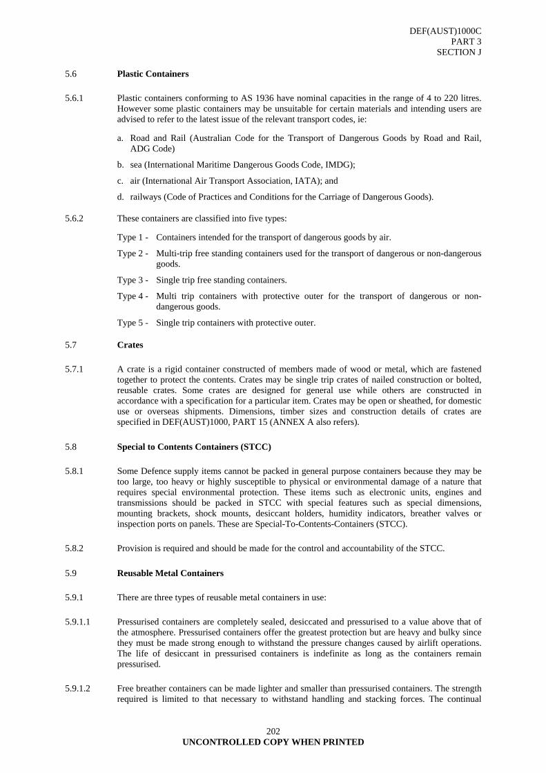
DEF(AUST)1000C PART 3
SECTION J
202 UNCONTROLLED COPY WHEN PRINTED
5.6 Plastic Containers
5.6.1 Plastic containers conforming to AS 1936 have nominal capacities in the range of 4 to 220 litres. However some plastic containers may be unsuitable for certain materials and intending users are advised to refer to the latest issue of the relevant transport codes, ie:
a. Road and Rail (Australian Code for the Transport of Dangerous Goods by Road and Rail, ADG Code)
b. sea (International Maritime Dangerous Goods Code, IMDG);
c. air (International Air Transport Association, IATA); and
d. railways (Code of Practices and Conditions for the Carriage of Dangerous Goods).
5.6.2 These containers are classified into five types:
Type 1 - Containers intended for the transport of dangerous goods by air.
Type 2 - Multi-trip free standing containers used for the transport of dangerous or non-dangerous goods.
Type 3 - Single trip free standing containers.
Type 4 - Multi trip containers with protective outer for the transport of dangerous or non-dangerous goods.
Type 5 - Single trip containers with protective outer.
5.7 Crates
5.7.1 A crate is a rigid container constructed of members made of wood or metal, which are fastened together to protect the contents. Crates may be single trip crates of nailed construction or bolted, reusable crates. Some crates are designed for general use while others are constructed in accordance with a specification for a particular item. Crates may be open or sheathed, for domestic use or overseas shipments. Dimensions, timber sizes and construction details of crates are specified in DEF(AUST)1000, PART 15 (ANNEX A also refers).
5.8 Special to Contents Containers (STCC)
5.8.1 Some Defence supply items cannot be packed in general purpose containers because they may be too large, too heavy or highly susceptible to physical or environmental damage of a nature that requires special environmental protection. These items such as electronic units, engines and transmissions should be packed in STCC with special features such as special dimensions, mounting brackets, shock mounts, desiccant holders, humidity indicators, breather valves or inspection ports on panels. These are Special-To-Contents-Containers (STCC).
5.8.2 Provision is required and should be made for the control and accountability of the STCC.
5.9 Reusable Metal Containers
5.9.1 There are three types of reusable metal containers in use:
5.9.1.1 Pressurised containers are completely sealed, desiccated and pressurised to a value above that of the atmosphere. Pressurised containers offer the greatest protection but are heavy and bulky since they must be made strong enough to withstand the pressure changes caused by airlift operations. The life of desiccant in pressurised containers is indefinite as long as the containers remain pressurised.
5.9.1.2 Free breather containers can be made lighter and smaller than pressurised containers. The strength required is limited to that necessary to withstand handling and stacking forces. The continual
DEF(AUST)1000C PART 3
SECTION J
203 UNCONTROLLED COPY WHEN PRINTED
breathing however allows a considerable amount of moisture to enter the atmospheric container and this soon saturates the desiccant. The life span of the desiccant in a free breather container depends on atmospheric humidity.
5.9.1.3 Valve controlled breather containers have valves which are closed at normal pressure, opening when the container interior pressure is beyond predetermined limits. In this way the amount of breathing is reduced and desiccant life increased. Controlled breather containers are a compromise between pressurised and free breather containers. By selecting breather valves with a proper operating pressure, breathing can be reduced and the life of the desiccant extended considerably. The valves also allow the container to be less heavily constructed than a pressurised container since only moderate pressures can build up inside. No definite storage life can be given for items enclosed in controlled breather containers as the life varies with the value settings and the atmospheric conditions.
6. CONTAINER HUMIDITY CONTROL
6.1 Breather Valves
6.1.1 A breather valve must perform two functions:
a. prevent the entry of moisture into the containers; and
b. prevent excessively high or low pressure, which may damage the container.
6.1.2 To accomplish these the valve must have a low leakage rate, a high cracking (operating) reliability and a high flow rate after cracking. Excessive valve leakage permits a container to breathe before the designed cracking pressure is reached and can reduce container life. Some leakage is unavoidable since no valve seal is perfect. When a valve nears its cracking pressure, it begins to unseat and will leak before is actually cracks. The same situation occurs when a valve reseats and some leakage will occur before total reseating. Leakage is also a function of valve age and environment, which can cause deterioration to the valve seat and spring. Therefore careful consideration should be given to materials used in construction. Foreign particles entering the valve can cause malfunction if a screen or protective cover is not provided. Breather valves are available in cracking pressure ranging from 3 to 70 kPa. The higher the cracking pressure the less often a valve will breathe, but the heavier and stronger the container must be made to withstand the pressure. A choice must be made to withstand the pressure. A choice must be made according to container design strength, desiccant load and desired life of the container. High accuracy in cracking pressure is not necessary; positive cracking action is critical however since failure to crack can damage the container.
6.2 Types of Valves
6.2.1 There are three types of breather valves:
a. vacuum relief;
b. pressure relief; and
c. combined vacuum and pressure relief.
6.2.2 The selection of the type depends on the container design configuration. Flow rates of container valves are dependent on the maximum pressure differential expected to be built up in the container and, in the case of airlift, the rate of pressure change caused by aircraft ascent and descent.
6.3 Temperature and Pressure Considerations
6.3.1 The container's internal temperature is affected by the direct contact with the atmosphere resulting in heat conduction and also by solar radiation directly on the surface of the container. At night containers assume the temperature of the atmosphere. During a bright day, the internal temperature reaches a value determined by solar radiation, but on cloudy days it tends to approximate closely
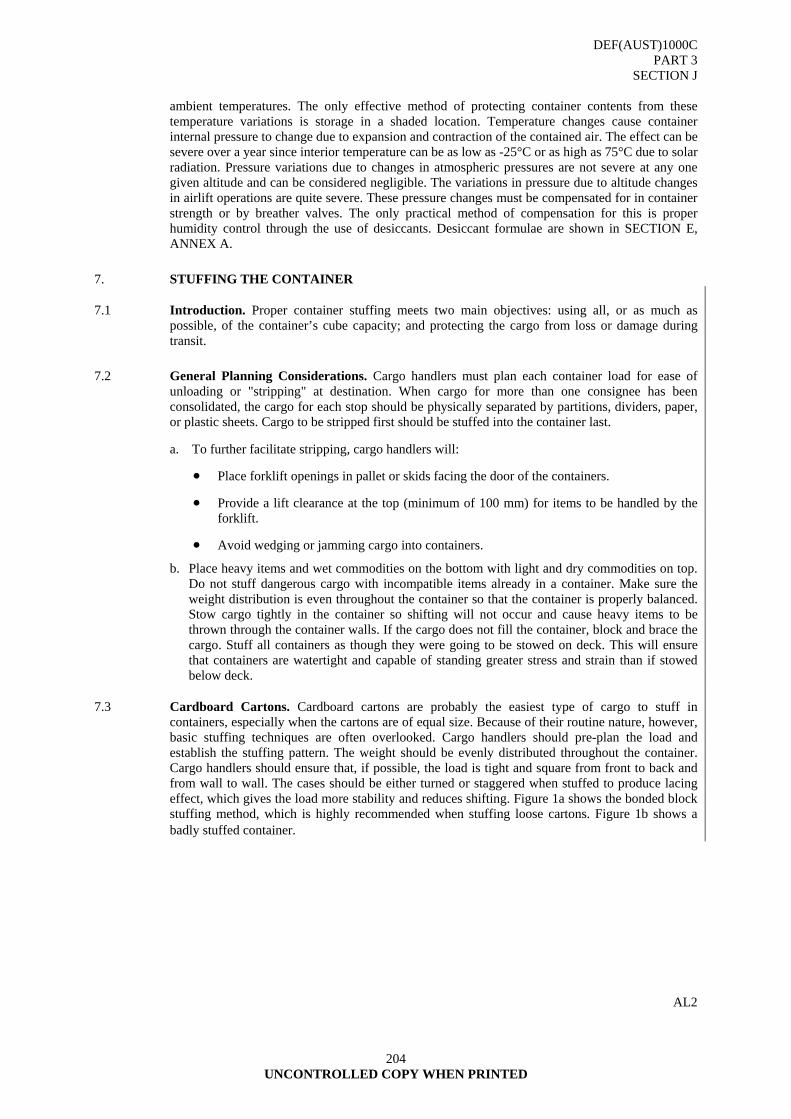
DEF(AUST)1000C PART 3
SECTION J
204 UNCONTROLLED COPY WHEN PRINTED
ambient temperatures. The only effective method of protecting container contents from these temperature variations is storage in a shaded location. Temperature changes cause container internal pressure to change due to expansion and contraction of the contained air. The effect can be severe over a year since interior temperature can be as low as -25°C or as high as 75°C due to solar radiation. Pressure variations due to changes in atmospheric pressures are not severe at any one given altitude and can be considered negligible. The variations in pressure due to altitude changes in airlift operations are quite severe. These pressure changes must be compensated for in container strength or by breather valves. The only practical method of compensation for this is proper humidity control through the use of desiccants. Desiccant formulae are shown in SECTION E, ANNEX A.
7. STUFFING THE CONTAINER
7.1 Introduction. Proper container stuffing meets two main objectives: using all, or as much as possible, of the container’s cube capacity; and protecting the cargo from loss or damage during transit.
7.2 General Planning Considerations. Cargo handlers must plan each container load for ease of unloading or "stripping" at destination. When cargo for more than one consignee has been consolidated, the cargo for each stop should be physically separated by partitions, dividers, paper, or plastic sheets. Cargo to be stripped first should be stuffed into the container last.
a. To further facilitate stripping, cargo handlers will:
• Place forklift openings in pallet or skids facing the door of the containers.
• Provide a lift clearance at the top (minimum of 100 mm) for items to be handled by the forklift.
• Avoid wedging or jamming cargo into containers.
b. Place heavy items and wet commodities on the bottom with light and dry commodities on top. Do not stuff dangerous cargo with incompatible items already in a container. Make sure the weight distribution is even throughout the container so that the container is properly balanced. Stow cargo tightly in the container so shifting will not occur and cause heavy items to be thrown through the container walls. If the cargo does not fill the container, block and brace the cargo. Stuff all containers as though they were going to be stowed on deck. This will ensure that containers are watertight and capable of standing greater stress and strain than if stowed below deck.
7.3 Cardboard Cartons. Cardboard cartons are probably the easiest type of cargo to stuff in containers, especially when the cartons are of equal size. Because of their routine nature, however, basic stuffing techniques are often overlooked. Cargo handlers should pre-plan the load and establish the stuffing pattern. The weight should be evenly distributed throughout the container. Cargo handlers should ensure that, if possible, the load is tight and square from front to back and from wall to wall. The cases should be either turned or staggered when stuffed to produce lacing effect, which gives the load more stability and reduces shifting. Figure 1a shows the bonded block stuffing method, which is highly recommended when stuffing loose cartons. Figure 1b shows a badly stuffed container.
AL2
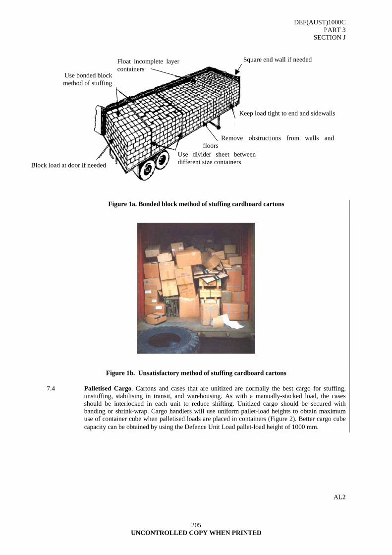
DEF(AUST)1000C PART 3
SECTION J
205 UNCONTROLLED COPY WHEN PRINTED
Figure 1a. Bonded block method of stuffing cardboard cartons
Figure 1b. Unsatisfactory method of stuffing cardboard cartons
7.4 Palletised Cargo. Cartons and cases that are unitized are normally the best cargo for stuffing, unstuffing, stabilising in transit, and warehousing. As with a manually-stacked load, the cases should be interlocked in each unit to reduce shifting. Unitized cargo should be secured with banding or shrink-wrap. Cargo handlers will use uniform pallet-load heights to obtain maximum use of container cube when palletised loads are placed in containers (Figure 2). Better cargo cube capacity can be obtained by using the Defence Unit Load pallet-load height of 1000 mm.
AL2
Keep load tight to end and sidewalls
Remove obstructions from walls andfloors
Square end wall if needed
Use divider sheet betweendifferent size containers Block load at door if needed
Float incomplete layercontainers
Use bonded blockmethod of stuffing
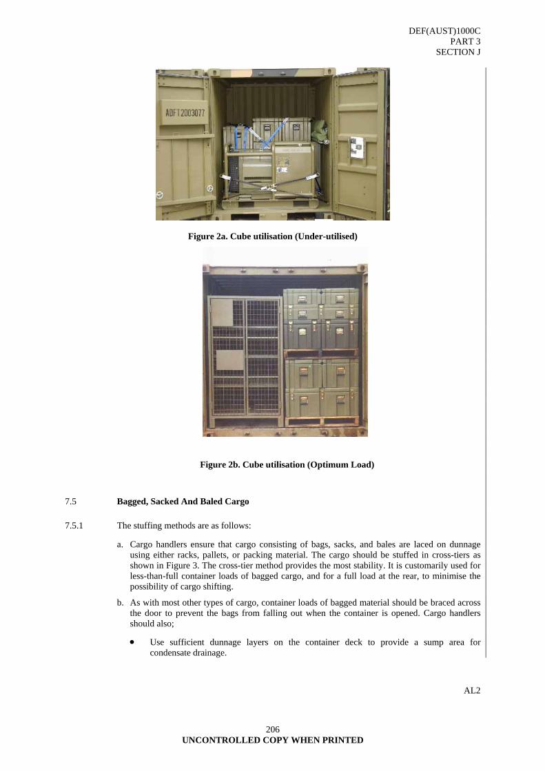
DEF(AUST)1000C PART 3
SECTION J
206 UNCONTROLLED COPY WHEN PRINTED
Figure 2a. Cube utilisation (Under-utilised)
7.5 Bagged, Sacked And Baled Cargo
7.5.1 The stuffing methods are as follows:
a. Cargo handlers ensure that cargo consisting of bags, sacks, and bales are laced on dunnage using either racks, pallets, or packing material. The cargo should be stuffed in cross-tiers as shown in Figure 3. The cross-tier method provides the most stability. It is customarily used for less-than-full container loads of bagged cargo, and for a full load at the rear, to minimise the possibility of cargo shifting.
b. As with most other types of cargo, container loads of bagged material should be braced across the door to prevent the bags from falling out when the container is opened. Cargo handlers should also;
• Use sufficient dunnage layers on the container deck to provide a sump area for condensate drainage.
AL2
Figure 2b. Cube utilisation (Optimum Load)
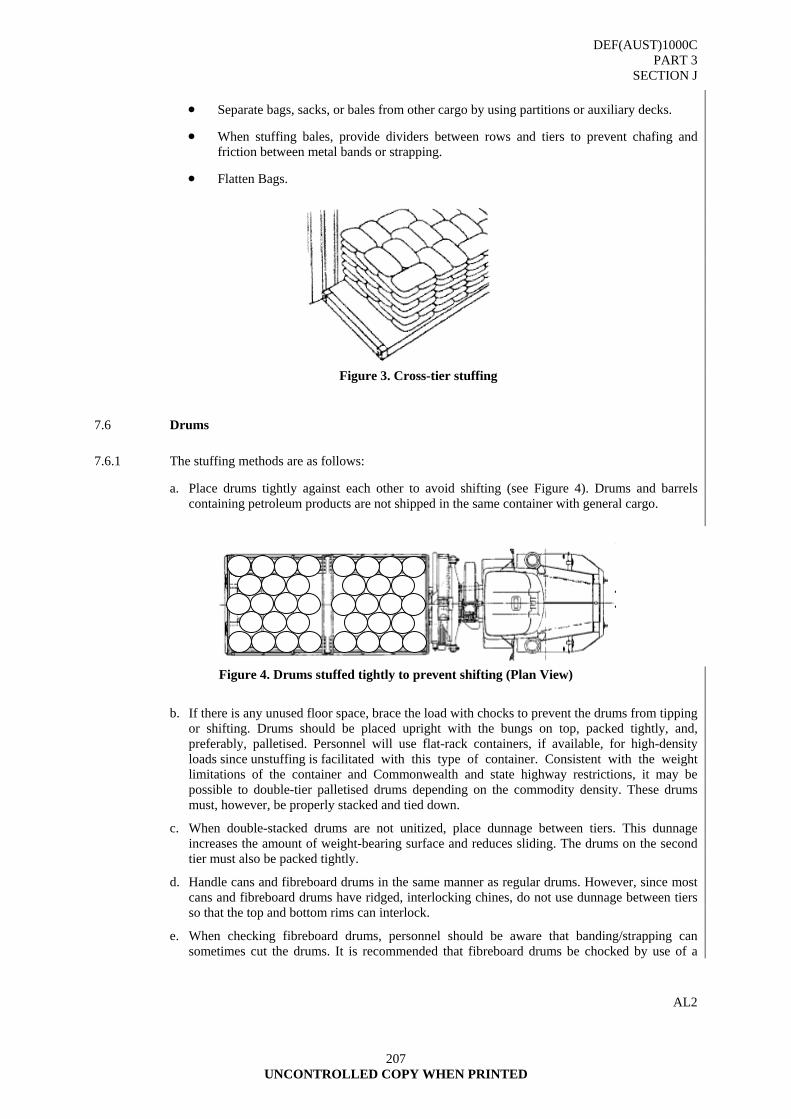
DEF(AUST)1000C PART 3
SECTION J
207 UNCONTROLLED COPY WHEN PRINTED
• Separate bags, sacks, or bales from other cargo by using partitions or auxiliary decks.
• When stuffing bales, provide dividers between rows and tiers to prevent chafing and friction between metal bands or strapping.
• Flatten Bags.
7.6 Drums
7.6.1 The stuffing methods are as follows:
a. Place drums tightly against each other to avoid shifting (see Figure 4). Drums and barrels containing petroleum products are not shipped in the same container with general cargo.
Figure 4. Drums stuffed tightly to prevent shifting (Plan View)
b. If there is any unused floor space, brace the load with chocks to prevent the drums from tipping or shifting. Drums should be placed upright with the bungs on top, packed tightly, and, preferably, palletised. Personnel will use flat-rack containers, if available, for high-density loads since unstuffing is facilitated with this type of container. Consistent with the weight limitations of the container and Commonwealth and state highway restrictions, it may be possible to double-tier palletised drums depending on the commodity density. These drums must, however, be properly stacked and tied down.
c. When double-stacked drums are not unitized, place dunnage between tiers. This dunnage increases the amount of weight-bearing surface and reduces sliding. The drums on the second tier must also be packed tightly.
d. Handle cans and fibreboard drums in the same manner as regular drums. However, since most cans and fibreboard drums have ridged, interlocking chines, do not use dunnage between tiers so that the top and bottom rims can interlock.
e. When checking fibreboard drums, personnel should be aware that banding/strapping can sometimes cut the drums. It is recommended that fibreboard drums be chocked by use of a
AL2
Figure 3. Cross-tier stuffing
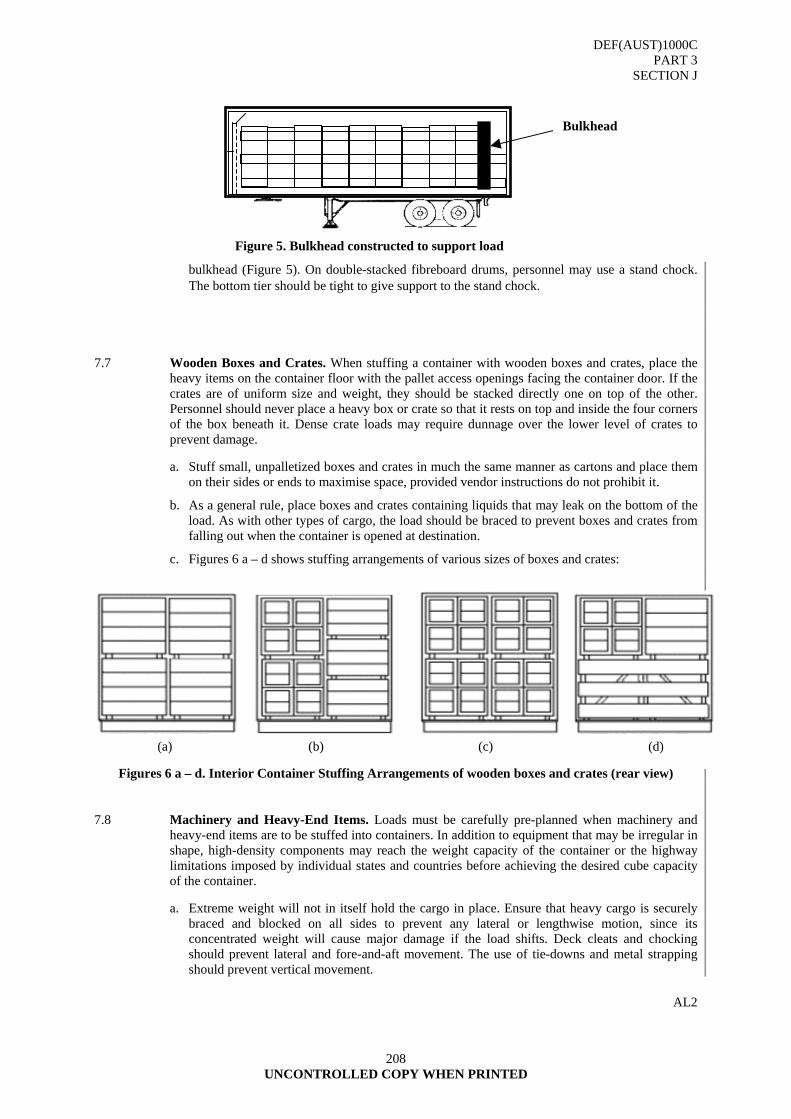
DEF(AUST)1000C PART 3
SECTION J
208 UNCONTROLLED COPY WHEN PRINTED
bulkhead (Figure 5). On double-stacked fibreboard drums, personnel may use a stand chock. The bottom tier should be tight to give support to the stand chock.
7.7 Wooden Boxes and Crates. When stuffing a container with wooden boxes and crates, place the heavy items on the container floor with the pallet access openings facing the container door. If the crates are of uniform size and weight, they should be stacked directly one on top of the other. Personnel should never place a heavy box or crate so that it rests on top and inside the four corners of the box beneath it. Dense crate loads may require dunnage over the lower level of crates to prevent damage.
a. Stuff small, unpalletized boxes and crates in much the same manner as cartons and place them on their sides or ends to maximise space, provided vendor instructions do not prohibit it.
b. As a general rule, place boxes and crates containing liquids that may leak on the bottom of the load. As with other types of cargo, the load should be braced to prevent boxes and crates from falling out when the container is opened at destination.
c. Figures 6 a – d shows stuffing arrangements of various sizes of boxes and crates:
Figures 6 a – d. Interior Container Stuffing Arrangements of wooden boxes and crates (rear view)
7.8 Machinery and Heavy-End Items. Loads must be carefully pre-planned when machinery and heavy-end items are to be stuffed into containers. In addition to equipment that may be irregular in shape, high-density components may reach the weight capacity of the container or the highway limitations imposed by individual states and countries before achieving the desired cube capacity of the container.
a. Extreme weight will not in itself hold the cargo in place. Ensure that heavy cargo is securely braced and blocked on all sides to prevent any lateral or lengthwise motion, since its concentrated weight will cause major damage if the load shifts. Deck cleats and chocking should prevent lateral and fore-and-aft movement. The use of tie-downs and metal strapping should prevent vertical movement.
AL2
Figure 5. Bulkhead constructed to support load
Bulkhead
(a) (b) (c) (d)
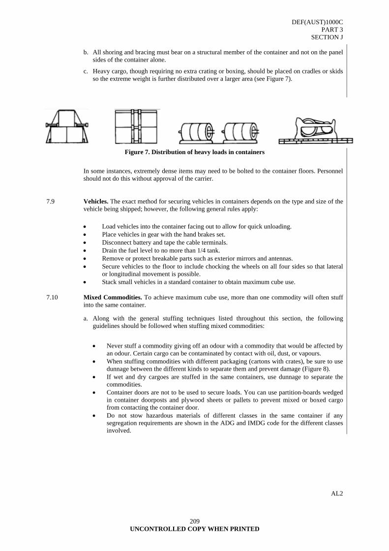
DEF(AUST)1000C PART 3
SECTION J
209 UNCONTROLLED COPY WHEN PRINTED
b. All shoring and bracing must bear on a structural member of the container and not on the panel sides of the container alone.
c. Heavy cargo, though requiring no extra crating or boxing, should be placed on cradles or skids so the extreme weight is further distributed over a larger area (see Figure 7).
Figure 7. Distribution of heavy loads in containers
In some instances, extremely dense items may need to be bolted to the container floors. Personnel should not do this without approval of the carrier.
7.9 Vehicles. The exact method for securing vehicles in containers depends on the type and size of the vehicle being shipped; however, the following general rules apply:
• Load vehicles into the container facing out to allow for quick unloading. • Place vehicles in gear with the hand brakes set. • Disconnect battery and tape the cable terminals. • Drain the fuel level to no more than 1/4 tank. • Remove or protect breakable parts such as exterior mirrors and antennas. • Secure vehicles to the floor to include chocking the wheels on all four sides so that lateral
or longitudinal movement is possible. • Stack small vehicles in a standard container to obtain maximum cube use.
7.10 Mixed Commodities. To achieve maximum cube use, more than one commodity will often stuff into the same container.
a. Along with the general stuffing techniques listed throughout this section, the following guidelines should be followed when stuffing mixed commodities:
• Never stuff a commodity giving off an odour with a commodity that would be affected by
an odour. Certain cargo can be contaminated by contact with oil, dust, or vapours. • When stuffing commodities with different packaging (cartons with crates), be sure to use
dunnage between the different kinds to separate them and prevent damage (Figure 8). • If wet and dry cargoes are stuffed in the same containers, use dunnage to separate the
commodities. • Container doors are not to be used to secure loads. You can use partition-boards wedged
in container doorposts and plywood sheets or pallets to prevent mixed or boxed cargo from contacting the container door.
• Do not stow hazardous materials of different classes in the same container if any segregation requirements are shown in the ADG and IMDG code for the different classes involved.
AL2

DEF(AUST)1000C PART 3
SECTION J
210 UNCONTROLLED COPY WHEN PRINTED
b. Sound judgment is the most important basis for determining when commodities can be mixed and what stuffing method is the best to be used to ensure the arrival of cargo at its destination without any damage.
7.11 Perishables. The refrigerator container should be inspected for cleanliness and should be pre-cooled before loading. Some containers have drain holes in the bottom for cleaning purposes. Since these holes permit the entry of outside air and affect the temperature, they must be closed/sealed before cargo is loaded in the container. The cargo should then be loaded as quickly as possible into the container, normally without lathing or dunnage placed between rows or layers of cargo. The cargo should not be packed tightly to the interior roof of the containers or hard against the doors, because sufficient air space must be left to provide proper air circulation within the container (Figure 9) contains more information on stowing refrigerated cargo and adequate air circulation.
a. Frozen foods do not generate heat. Stowing boxes of frozen commodities tightly will prevent heat entry and surround the items with a blanket of cold air (Figure 10).
b. When loading is complete, close the doors and affix the seal. On the record chart write the date and time of loading, temperature setting, and the name and voyage number of the vessel on which the container will be loaded.
AL2
Dunnage
Figure 8. Dunnage separating mixed commodities
HEAT
COOL
WARM
Figure 9. Stuffing perishable commodities
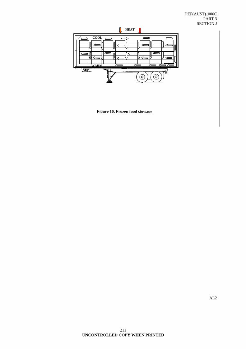
DEF(AUST)1000C PART 3
SECTION J
211 UNCONTROLLED COPY WHEN PRINTED
AL2
HEAT
COOL
WARM
Figure 10. Frozen food stowage

DEF(AUST)1000C
PART 3 SECTION J ANNEX A
UNCONTROLLED COPY WHEN PRINTED
212
ANNEX A
CONTAINER TYPE AND STYLE
A1. DEF(AUST)1000, PART 15, details requirements for the manufacture and supply of Boxes, Fibreboard
and Wood based on the 1100 mm pallet. The boxes are divided into the following types and classes: Box Type 1 - Box, fibreboard, solid, regular slotted. Data Sheet No 2 Box Type 2 - Box, fibreboard, corrugated, single wall, double faced, regular slotted. Data Sheet No 3 Box Type 3 - Box, fibreboard, corrugated, double wall, regular slotted. Data Sheet No 4 Box Type 4 - Box, fibreboard, corrugated, triple wall, Styles TW1 – 7 Type 1 Lightweight Data Sheet Class 1 - Timber No 1 Class 2 – Non battened No 2 Class 3 – Battened (6mm timber) No 3 Class 4 – Battened (12mm timber) No 4 Type 2 Medium Weight Data Sheet Class 1 – Plywood panel cleated No 5 Class 2 – Non battened No 6 Class 3 - Battened No 7 Class 4 – Battened, two man lift No 8 Type 3 Heavy Weight Data Sheet Class 1 – Battened, mechanical lift No 9 Class 2 – Battened, mechanical lift, heavy duty No 10
DEF(AUST)1000C
PART 3 SECTION J ANNEX A
213 UNCONTROLLED COPY WHEN PRINTED
A2. Specification DEF(AUST)1000, part 15, details requirements for the manufacture and supply of crate,
wood, open and sheathed. The crates shall be supplied in the following classes and styles: Class 1 Crates, wood, open Style 1 - up to 50 kg gross Data Sheet No 2 Style 2 - up to 100 kg gross Data Sheet No 3 Style 3 - up to 200 kg gross Data Sheet No 4 Style 4 - up to 500 kg gross Data Sheet No 5 Style 5 - up to 1000 kg gross Data Sheet No 6 Class 2 Crates, wood, sheathed Style 1 - up to 1100 mm long and up to 1100 mm deep Data Sheet No 7 Style 2 - up to 1100 mm long and up to 1100 mm deep Data Sheet No 8 Style 3 - over 1100 mm long and over 1100 mm deep Data Sheet No 9
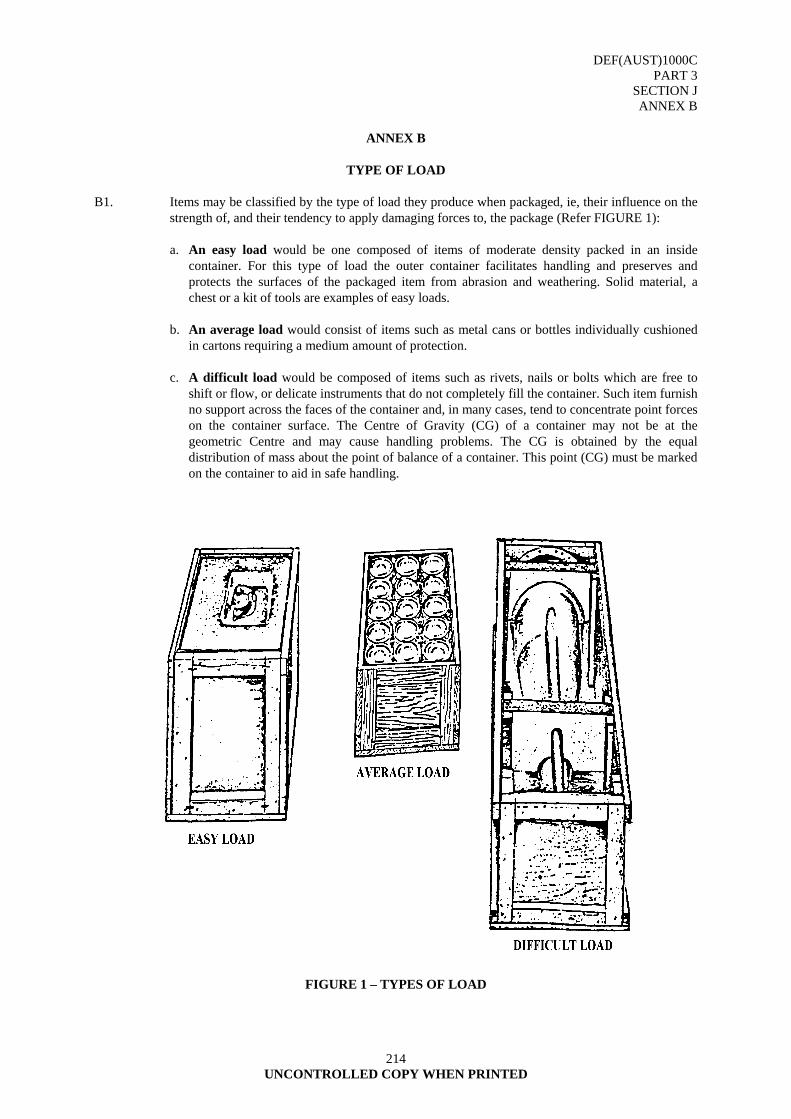
DEF(AUST)1000C
PART 3 SECTION J ANNEX B
214 UNCONTROLLED COPY WHEN PRINTED
ANNEX B
TYPE OF LOAD
B1. Items may be classified by the type of load they produce when packaged, ie, their influence on the
strength of, and their tendency to apply damaging forces to, the package (Refer FIGURE 1): a. An easy load would be one composed of items of moderate density packed in an inside
container. For this type of load the outer container facilitates handling and preserves and protects the surfaces of the packaged item from abrasion and weathering. Solid material, a chest or a kit of tools are examples of easy loads.
b. An average load would consist of items such as metal cans or bottles individually cushioned
in cartons requiring a medium amount of protection. c. A difficult load would be composed of items such as rivets, nails or bolts which are free to
shift or flow, or delicate instruments that do not completely fill the container. Such item furnish no support across the faces of the container and, in many cases, tend to concentrate point forces on the container surface. The Centre of Gravity (CG) of a container may not be at the geometric Centre and may cause handling problems. The CG is obtained by the equal distribution of mass about the point of balance of a container. This point (CG) must be marked on the container to aid in safe handling.
FIGURE 1 – TYPES OF LOAD
DEF(AUST)1000C PART 3
SECTION K
UNCONTROLLED COPY WHEN PRINTED
215
SECTION K - TECHNICAL REQUIREMENTS FOR PROTECTION DURING DISTRIBUTION - FASTENERS AND CLOSURES
1. GENERAL
1.1 Typical fasteners include links, hooks, clinches, rivets, clamps, ties, bolts, screws, nails and tacks. Typical closures include latches, straps and binders. Fasteners and closures are used in the following ways in packing:
a. to fabricate containers;
b. to secure items within containers;
c. to close containers; and
d. to secure shipping containers to skids and pallets.
1.2 Methods
Since the design of packages is affected by the adequacy of these operations, a knowledge of the common methods used is relevant to package design and selection of containers. Fastening and closing methods for the following containers are:
a. Cleated Plywood Boxes - Nailing.
b. Nailed and Lock-corner Wooden Boxes - Nailing or stapling and strapping.
c. Wooden Boxes - Nailing or stapling and strapping.
d. Wooden Crates - Nailing and bolting construction. Strapping and nailing or stapling.
e. Timber and Plywood Sheathed Crates - Nailing or strapping and bolting.
f. Wood-cleated Fibreboard Boxes - Strapping.
g. Corrugated Fibreboard Boxes - Tapes, staples and adhesives.
h. Metal Cans - Closures such as screw or lug caps, friction tops, hermetic seals or slipcovers are used, depending on contents.
i. Pails - Friction tops, slip covers and lug or bolt rings.
j. Steel Shipping Containers - lug-type locking rings. 2. FASTENERS
2.1 Selection
The fabrication of a satisfactory wooden container depends on the selection and use of:
a. the proper sizes of timber; and
b. the various methods of fastening.
2.2 Method
Boxes are assembled with nails, screws, staples and corrugated fasteners. Screws may be substituted for nails although the latter are preferred for most applications. Screws, however, are sometimes desirable particularly when the contents of the box require inspection during storage. In such cases screws may be substituted for nails in the top of the box, but use of quick-release fasteners or catches may save time.
DEF(AUST)1000C PART 3
SECTION K
216 UNCONTROLLED COPY WHEN PRINTED
3. NAILING
3.1 Availability. Nails are the most common fastenings for boxes, blocks and braces. Common types of nails available and information on these are given in AS 2334.
3.1.1 Box Construction Defects. Tests of packing boxes indicate that the most common defect in box construction is inadequate nailing. Attempts to strengthen boxes by the use of thicker timber without regard for nailing often waste material without achieving the desired results.
3.1.2 Nailing Techniques. The following general characteristics of nails should be considered in box construction:
a. Cement-coated or chemically etched nails have a holding power considerably greater than smooth nails. About 25 percent more nails of the same size are needed when smooth nails are used in place of cement-coated or chemically etched nails.
b. The sizes of nails and cleats for fastening sides, tops and bottom to end boards are determined by the type of wood used as well as by the size of the members.
c. The nails commonly used in box fabrication are bullet-head flat head and panel pin. These may be used in combinations of cement-coated galvanised or teflon coated. Also in use are mechanically deformed nails, designed for added holding power.
d. A slender nail is likely to hold better than a thick nail because the slender nail bends near the surface of the pieces joined without loosening the friction grip of the nail shank.
e. Nails spaced closely in a line parallel to the grain induce splitting. The first and last nails should be spaced one-half of the specified spacing from the ends of the nailing edge, but no less than 20 mm. If it is necessary to exceed this spacing because of small knots or checks in the nailing end, or because of the location of joints between boards, the distance between any two adjacent nails should not be greater than one and one-half times the prescribed spacing.
f. If the desired nail size is not available, one size smaller may be used and the nails should be spaced 5 mm closer than is required for the size of the nail originally specified.
g. At least two nails should be used in each end of each board.
h. Wherever cleats are used in the end construction, approximately one-half of the nails used to secure lengthwise boards, joining top, bottom or sides to cleat edges should be driven into the end and the remainder into the cleat.
i. All nails should be so driven that no part projects above the surface of the wood. No nails should be over-driven more than one-eighth the thickness of the timber because this tends to crush the wood around the head, thus weakening the joint.
j. End grain nailing should be avoided.
k. When nailing cleats or battens to the sides, top or bottom, nails should pass through both pieces and be clinched not less than 3 mm. Clinching, in effect, makes the nail act as a rivet, thus increasing its resistance to withdrawal. Either cement-coated, chemically etched or bright uncoated nails may be used if they are to be clinched.
3.1.3 Blocking and Bracing. Nails used in blocking and bracing should be cement-coated or chemically etched, particularly when the nails cannot be clinched. Flathead nails are particularly well suited for use with interior packing. They are relatively slender, can be driven into the denser woods, withstand shocks well and the heads do not break off or pull through the wood easily. Because of their larger heads, clout nails are recommended where plywood of 13 mm or less is used. Whenever possible, nails should be applied so that they are subjected to forces of lateral displacement rather than direct withdrawal.
DEF(AUST)1000C PART 3
SECTION K
217 UNCONTROLLED COPY WHEN PRINTED
4. CORRUGATED FASTENERS
4.1 Use. When it is necessary to use two or more pieces to form the sides, top or bottom of a box, the pieces may be butt-joined and fastened together with corrugated fasteners. Although they contribute little to the strength of the box, especially where the moisture content of the wood is high, they have two main uses:
a. during manufacture, they facilitate handling; and
b. during shipment, they discourage pilferers from cutting nails and sliding intermediate boards out of the way to gain access to the contents. The length of the corrugated fasteners used should never exceed three-quarters of the thickness of the piece being fastened.
5. BOLTS, SCREWS AND RIVETS (Selection of)
5.1 Selection. The selection of bolts, screws or rivets for any given job requires close examination of the following.
5.1.1 Type of Service. Will the assembly be subject to vibration, impact loads, tension or shear stresses or a combination of these? The type of closure used should accommodate those stresses expected. Is repeated dismantling required? Self-tapping screws must not be used unless fastening is of a permanent nature. Butterfly nuts and bolts would solve the problem more easily.
5.1.2 Materials Being Joined. Will rivets, self-tapping screws, nut plates, clinch nuts and through bolts be used to assemble sheet-metal parts? Steel fasteners for non-ferrous metals may result in electrolysis and corrosion of the metals. Corrosion can be confined to an insert without damage to a screw used with it. Inserts in plastics or soft metals protect against thread damage when frequent dismantling is required.
5.1.3 Economy. It is not economical to use too many or too few fasteners nor ones, which are too large or too small, since quality will inevitably be affected.
5.1.4 Materials for Bolts, Screws and Nuts. The principal metals used for bolts, screws and nuts are iron, steel, aluminium and brass. Nylon, polyethylene and other plastic nuts, screws and various fasteners are light in weight, immune to corrosion and moisture, tough and resilient. For many applications, they can do a job metal fasteners cannot accomplish. The plastic fasteners are generally at a disadvantage when:
a. fastener cost alone is important;
b. requirements of stress and shear are high; and
c. temperature conditions are higher than 180°C. 6. SCREWS
6.1 Self-tapping and drive screws have wide application in sheet metal work, wood and plastics. A lead hole must be provided for the self-tapping types, but tapping is eliminated. Data on various screws are provided in AS 1111 and AS 1110.
7. BOLTS
7.1 Types. Bolts are of two basic types:
a. those which are driven into drilled or tapped holes; and
b. those which require a nut and washer for securing.
7.2 Applications. The type selected will depend on the need for easy removal. Bolts commonly used for blocking and bracing are coach, carriage and machine bolts. U or J-bolts are used for special conditions where regular bolts cannot be applied. Tie rods and J-bolts are actually extended bolts
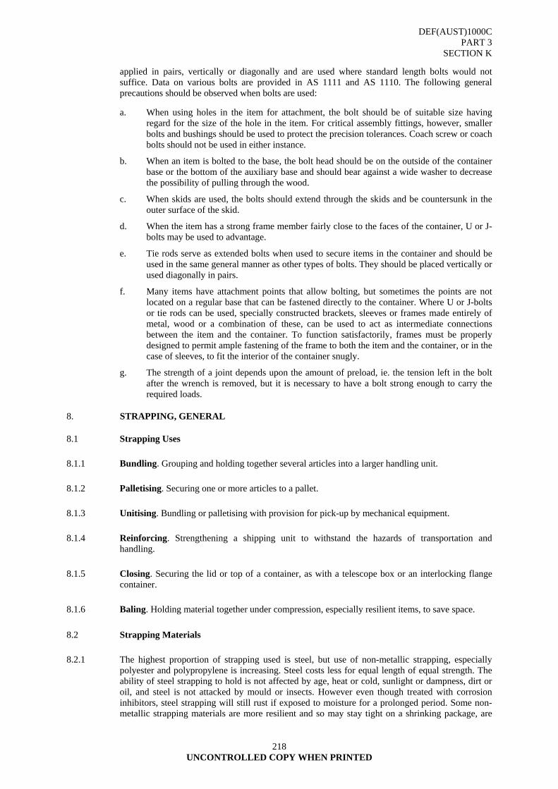
DEF(AUST)1000C PART 3
SECTION K
218 UNCONTROLLED COPY WHEN PRINTED
applied in pairs, vertically or diagonally and are used where standard length bolts would not suffice. Data on various bolts are provided in AS 1111 and AS 1110. The following general precautions should be observed when bolts are used:
a. When using holes in the item for attachment, the bolt should be of suitable size having regard for the size of the hole in the item. For critical assembly fittings, however, smaller bolts and bushings should be used to protect the precision tolerances. Coach screw or coach bolts should not be used in either instance.
b. When an item is bolted to the base, the bolt head should be on the outside of the container base or the bottom of the auxiliary base and should bear against a wide washer to decrease the possibility of pulling through the wood.
c. When skids are used, the bolts should extend through the skids and be countersunk in the outer surface of the skid.
d. When the item has a strong frame member fairly close to the faces of the container, U or J-bolts may be used to advantage.
e. Tie rods serve as extended bolts when used to secure items in the container and should be used in the same general manner as other types of bolts. They should be placed vertically or used diagonally in pairs.
f. Many items have attachment points that allow bolting, but sometimes the points are not located on a regular base that can be fastened directly to the container. Where U or J-bolts or tie rods can be used, specially constructed brackets, sleeves or frames made entirely of metal, wood or a combination of these, can be used to act as intermediate connections between the item and the container. To function satisfactorily, frames must be properly designed to permit ample fastening of the frame to both the item and the container, or in the case of sleeves, to fit the interior of the container snugly.
g. The strength of a joint depends upon the amount of preload, ie. the tension left in the bolt after the wrench is removed, but it is necessary to have a bolt strong enough to carry the required loads.
8. STRAPPING, GENERAL
8.1 Strapping Uses
8.1.1 Bundling. Grouping and holding together several articles into a larger handling unit.
8.1.2 Palletising. Securing one or more articles to a pallet.
8.1.3 Unitising. Bundling or palletising with provision for pick-up by mechanical equipment.
8.1.4 Reinforcing. Strengthening a shipping unit to withstand the hazards of transportation and handling.
8.1.5 Closing. Securing the lid or top of a container, as with a telescope box or an interlocking flange container.
8.1.6 Baling. Holding material together under compression, especially resilient items, to save space.
8.2 Strapping Materials
8.2.1 The highest proportion of strapping used is steel, but use of non-metallic strapping, especially polyester and polypropylene is increasing. Steel costs less for equal length of equal strength. The ability of steel strapping to hold is not affected by age, heat or cold, sunlight or dampness, dirt or oil, and steel is not attacked by mould or insects. However even though treated with corrosion inhibitors, steel strapping will still rust if exposed to moisture for a prolonged period. Some non-metallic strapping materials are more resilient and so may stay tight on a shrinking package, are
DEF(AUST)1000C PART 3
SECTION K
219 UNCONTROLLED COPY WHEN PRINTED
light in weight and are non-staining. In selecting a strapping material, a number of factors should be considered:
a. price of strap;
b. strength;
c. elongation;
d. elastic recovery;
e. preferred method of application;
f. danger of rusting and of damage to the packaged goods;
g. safety hazards; and
h. disposability problems.
The prime requisite is whether the strap must restrict or accommodate movement of the package. ANNEX A, Strapping, (Metallic and Non-Metallic); provides information on a variety of strapping materials.
8.3 Metallic Strapping
8.3.1 Grades. Flat steel strapping is available in various thickness, widths and properties as follows:
a. High grade: manufactured from cold rolled, heat-treated, mill finished steel.
b. Standard Grade: manufactured from cold rolled, mill finished steel.
c. Heavy Duty: manufactured from hot or cold rolled, heat-treated steel, which is mill finished or galvanised.
Steel strapping is also supplied with a variety of coatings (e.g. galvanised) to provide long term protection against rust.
FLAT STEEL STRAPPING
8.4 Non-metallic Strapping
Non-metallic strapping is available in either polypropylene or polyester.
8.4.1 Polypropylene Strapping. A medium grade, general purpose strapping, used in the closure of fibreboard boxes and the restraining of loose items to form a single pack or load. The strapping is manufactured from extruded polypropylene in which the high tensile strength is developed by orientations.
DEF(AUST)1000C PART 3
SECTION K
220 UNCONTROLLED COPY WHEN PRINTED
8.4.2 Polyester Strapping. A high grade, high tensile strength, used in the closure of heavy-weight fibreboard boxes and for the bundling and restraining of loose items to form a single pack or load where extra strength and retained tension is required.
8.5 Hand Tools
A variety of tools are available for applying strapping.
8.5.1 Tensioners. These are used to tighten a loop of strapping around the object to be strapped by applying tension on two overlapping strap ends. Tensioning is produced by a wheel and ratchet arrangement or by a rack and pinion assembly. Most tensioners have a base, which goes under the strapping, which rests on a flat or nearly flat surface of the object. If this surface is narrow or it its girth is small, the freedom of the tensioner to move with take-up may be very limited. Some tension will be lost when the base is taken out from under the strapping. To avoid such loss, a pushtype tensioner, which has no base under the strap, is required. Since it operates by pushing against the seal (by 'tightening a slip knot'), the push-type tensioner requires that seals be threaded on to the strapping bend back under the seal. Push-type tensioners are preferred for small or irregular bundles and for narrow packages. The majority of strapping applications utilises conventional tensioners with a base under the strapping. These are usually faster to use than the push type and permit somewhat higher tensions to be attained, but they require a wide enough surface to permit the tool to move with take-up.
8.5.2 Sealers. Sealers are used to join the overlapping strap ends with a metal seal. They must do this reliably, always producing a strong, secure joint. A notch-type sealer cuts into the outer edges of the strapping and seal, and turns the resulting tabs down (regular notch) or up (reverse notch). This type is generally used on waxed or coated strapping. Another variation is a bend-producing machine, which corrugates the seal in the transverse direction. NATO Stock Number 3540-66-117-3299.
8.5.3 Cutter. This device allows steel strapping to be cut without the danger of the strapping 'flying' by providing a controlled means of releasing the tension in the strapping when it is cut. NATO Stock Number 5110-66-026-5286.
8.5.4 Combination Tools. The functions of both tensioner and sealer and often cutter as well may be provided in a single tool. It eliminates reaching for and then putting down these separate tools. A seal-feed combination tool carries seals in a magazine and eliminates reaching for the seal and manually placing it on the strapping. For most efficient use on a production line, a combination tool should be mounted close to its operating position.
8.6 Powered Strapping Machines
A powered strapping machine increase an operator's productivity, so that he can perform additional functions such as inspection, stacking, labelling, marking and the like, as well as speeding the strapping operation. In using a manually-operated power strapper, the operator positions the package in the machine, passes the end of the strapping over and down in front of the package, pushes the control and removes the package. These machines are less expensive and complex than more automatic control systems and can accommodate a variety of package shapes and sizes. Automatic machines require only three functions of the operator; positioning the package, switching on and removing the package. Operatorless machines make use of a powered conveyor and a system of automatic controls.
8.7 Use of Strapping
8.7.1 Precautions. General precautions on the use of metal strapping are:
a. where possible, the item and the support must be completely encircled. When it is impossible to do this, the two ends of the metal strapping must be anchored;
b. one-piece straps should be used wherever possible;
DEF(AUST)1000C PART 3
SECTION K
221 UNCONTROLLED COPY WHEN PRINTED
c. straps should be placed only on those strong parts of the item that can withstand the impact load and weight of the items;
d. where strapping passes over a sharp edge of the item, corner protectors may be required to protect the strapping from fracturing;
e. protecting materials should be used between the item and the strap if the strap might harm or scratch the item; and
f. strapping should be arranged on the container, where possible, to reinforce blocking and bracing; and annealed strapping should be used only for lightweight items because it stretches readily.
8.7.2 Precautionary Advice. The following general precautions are advisable:
a. Use strapping of an acceptable type conforming to the data contained in ANNEX A;
b. Use strapping of correct size and strength;
c. Use the correct number of straps depending upon the weight, contents and style of container;
d. Locate the strapping correctly;
e. All straps must be applied at right angles to the edges of the box over which they pass;
f. Use correct tensioning tools designed for particular type and style of strap;
g. Apply sufficient tension so that straps will sink into edges of container but do not over-tension to the point that the strapping is weakened or the container damaged. Conversely, the straps must not be so loose as to engage another box and interfere with the handling;
h. Avoid applying straps over voids where they will be a hazard to handling personnel and where they will not add to the strength of the container;
i. Do not apply straps on the bottom surface of skids. Notch the skid for the straps of place the straps so that they are between the skids; and
j. Strap the boxes just before shipping since most boxes shrink during long periods of storage. At the time of shipment any previously applied straps should be examined, and if found to be loose, the containers should be restrapped.
9. STAPLING
9.1 Advantages of Stapling
The main advantages of using staples as a closure device are:
9.1.1 Economy and Speed of Closure. The average case requires only four staples in the top and the same number in the bottom, and can be closed very quickly.
9.1.2 Security. Undetected pilfering is almost impossible. Staples give a very strong closure with which atmospheric conditions will not interfere.
9.1.3 Efficiency. The case is ready for dispatch as soon as it is sealed. The strength of the closure facilitates stacking.
9.2 Stapling Machines
A wide range of stapling equipment is available including portable machines, which can be either hand or air-operated. There are also production line machines, which will staple top and bottom, or either, or both ends of a case simultaneously, and also a completely automatic operatorless model. Such machines make use of retractable anvils to pierce the material, thus eliminating the need for fixed anvils, which greatly reduced the flexibility of the stapler. The machines are adjustable, so that it is possible to control the tightness with which the staple is clinched. There are many leg lengths of staple available; the length used being governed by the thickness of the board and also the case design.

DEF(AUST)1000C PART 3
SECTION K
222 UNCONTROLLED COPY WHEN PRINTED
9.3 Staple Support
It is not possible to drive the staples unless the case flaps are supported, and it is sometimes necessary to use a top pad of corrugated fibreboard to prevent damage to the contents. Staples may be used with solid or corrugated fibreboard cases. Some have been designed for use through fibreboard into wooden formers or frames.
9.4 Staple Use
Staples are used not only to close fibreboard boxes but also to assemble wooden boxes and crates as well as pallets. Staples have the advantage of being slim and since they are double pointed, they tend to hold timber without splitting. Thus they can be used closer to the ends and edges to timber than nails.
9.5 Staple Effectiveness.
Staples may be clinched or unclinched depending on the density of the medium into which they are driven. A variety of points are available. Various coatings are also applied for a dded holding power.
10. PRESSURE SENSITIVE ADHESIVE PACKAGING TAPES
10.1 Pressure-sensitive tapes will adhere to paper, paperboard, metal, glass or plastics. Such tapes need only the application of pressure to adhere to almost any surface. No special preparation before application is necessary, except to ensure that the surface of the material is clean. Pressure-sensitive tapes are manufactured from a wide range of substrates, with an adhesive normally formulated from a rubber or synthetic elastomer and a resin.
10.2 Paper Tapes
10.2.1 Crepe (Impregnated). Suitable for light duty packaging where strength is not required and a degree of stretch is acceptable. Not suitable for prolonged exterior exposure.
10.2.2 Flatback (Impregnated). For general purpose packaging requiring moderate strength, e.g., closure of fibreboard containers. Has greater edge tear resistance than crepe. Not suitable for prolonged exterior exposure.
10.2.3 Flatback, Kraft (Non-impregnated). Suitable only for light to medium duty packaging, where exterior exposure is not involved.
10.3 Filmic Tapes
10.3.1 Regenerated Cellulose Film. Cellulose film in transparent or coloured form is used for making tapes for sealing, parcelling and bundling. This tape is not waterproof but will resist oil, grease and many solvents.
10.3.2 Cellulose Acetate Film. This film is suitable for self-adhesive tape for special sealing duties in corrosive or damp conditions where normal cellulose tape would be unsuitable.
10.3.3 Polyvinyl Chloride (PVC)
10.3.3.1 Unplasticised. A sealing, labelling and closure tape with moderate conformability and high resistance to moisture, some solvents and some chemicals, it should not be subjected to elevated temperatures.
10.3.3.2 Plasticised. This tape is used for sealing and other packaging applications where a high degree of conformability is required, e.g., sealing bottles and cans. Its resistance to moisture, solvents and chemicals is similar to that of the unplasticised type.
DEF(AUST)1000C PART 3
SECTION K
223 UNCONTROLLED COPY WHEN PRINTED
10.3.4 Polyester (MYLAR). This tape is used for sealing and label protection and also for decorative purposes in coloured metallised form. It is thin, tough and highly resistant to moisture, most chemicals and solvents and has moderate conformability. With a suitable adhesive it has good resistance to elevated temperature.
10.3.5 Polyethylene. This sealing tape has high conformability, high resistance to most solvents and chemicals, and has low moisture transmission. The black-pigmented film also has good resistance to weathering.
10.3.6 Polypropylene
10.3.6.1 Biaxially Oriented. Sealing, labelling and closure tape with moderate conformability, high strength and good resistance to moisture, most solvents and chemicals. Resists impact breakage and edge tearing.
10.3.6.2 Monoxially Oriented. As for Biaxially oriented, but with much higher breaking strength and thus suitable for strapping, bundling and closure of heavy cartons. Resists impact breakage and edge tearing.
10.4 Cloth Tapes (Cotton Cloth)
10.4.1 Untreated. This tape is used for general purpose holding and securing with moderate strength and conformability. It is not suitable for prolonged exterior exposure.
10.4.2 PVC or Nitro-cellulose (NC) Coated Cloth. This tape has qualities similar to untreated cotton with improved moisture and weather resistance.
10.4.3 Polyethylene Coated Cloth. This tape has qualities similar to PVC or NC (coated) with very low moisture transmission.
10.5 Laminated Tapes
10.5.1 Properties. These tapes are mainly used for strapping including bundling and closure of heavy-duty cartons. Their strength is determined by the filament reinforcement. Further properties depend on other backing components (films, etc).
10.6 Considerations in Selecting a Tape.
The primary considerations in selecting a tape for a particular application are:
10.6.1 Surface to which Tape is to be Adhered. The tape must adhere to the surface being taped and remain adhered under all anticipated conditions of transportation and storage.
10.6.2 Removability. If adhered to the surface of an item, the tape must be removable without disturbing the item or impairing its function.
10.6.3 Application Conditions. Application conditions include temperature and humidity. These factors are important as they change the state of the adhesive side of the tape.
10.6.4 Mass and Size of the Package. The mass and size of the package determine the strength required of the tape.
10.6.5 Transportation and Storage Conditions. The tape must not deteriorate or lose its adhesiveness during transport and protects the package and the packaged item.
DEF(AUST)1000C PART 3
SECTION K
224 UNCONTROLLED COPY WHEN PRINTED
10.6.6 Cost. The cost of the tape must be kept at minimum, but the primary consideration is to choose a tape, which adequately protects the package and the packaged item.
10.7 Tape Specifications.
Physical specifications of the various tapes are given in AS 1599. 11. TWINE
11.1 The principal uses of twine are in baling of items, overwrapping to consolidate a group of items and as a reinforcement medium for other packages, notably kraft or paper coverings or hessian or other fabric or textile container.
DEF(AUST)1000C PART 3
SECTION K ANNEX A
UNCONTROLLED COPY WHEN PRINTED
225
ANNEX A
STRAPPING: METALLIC AND NON-METALLIC
A1. REQUIREMENTS A1.1 The following information covers the requirements for metallic and non- metallic tensional
strapping used for unitising, reinforcing and closure of packages. A1.2 Classification A1.2.1 The strapping shall be of the following types and grades:-
TYPE 1: - STEEL STRAPPING DATA SHEET
Grade I High Grade No. 1 Grade II Standard Grade No. 2 Grade III Heavy Duty Grade No. 3
TYPE 2: - NON-METALLIC STRAPPING DATA SHEET
Class 1 No. 4 Class 2 No. 5
A2. DEFINITIONS A2.1 For the purpose of this specification the following definitions shall apply: Camber. Is the greatest deviation of a side edge from a straight line. The measurement being
taken on the concave side. Coil Set. Height of rise at ends of strap. A3. REQUIREMENTS A3.1 General A3.1.1 The strapping shall be straight, smooth and clean, free from kinks, grooves, edge curvature,
indentation, cracks and other defects that might affect its serviceability. A3.1.2 The technical requirements for each type, grade and class of strapping are contained in separate
Data Sheets. These Data Sheets shall be read in conjunction with other requirements of this specification.
A3.2 Mechanical Properties A3.2.1 The mechanical properties of each type of strapping shall be as stated in the appropriate Data
Sheet. A3.3 Intended Use A3.3.1 The intended use of each type of strapping shall be as specified in the appropriate Data Sheet.
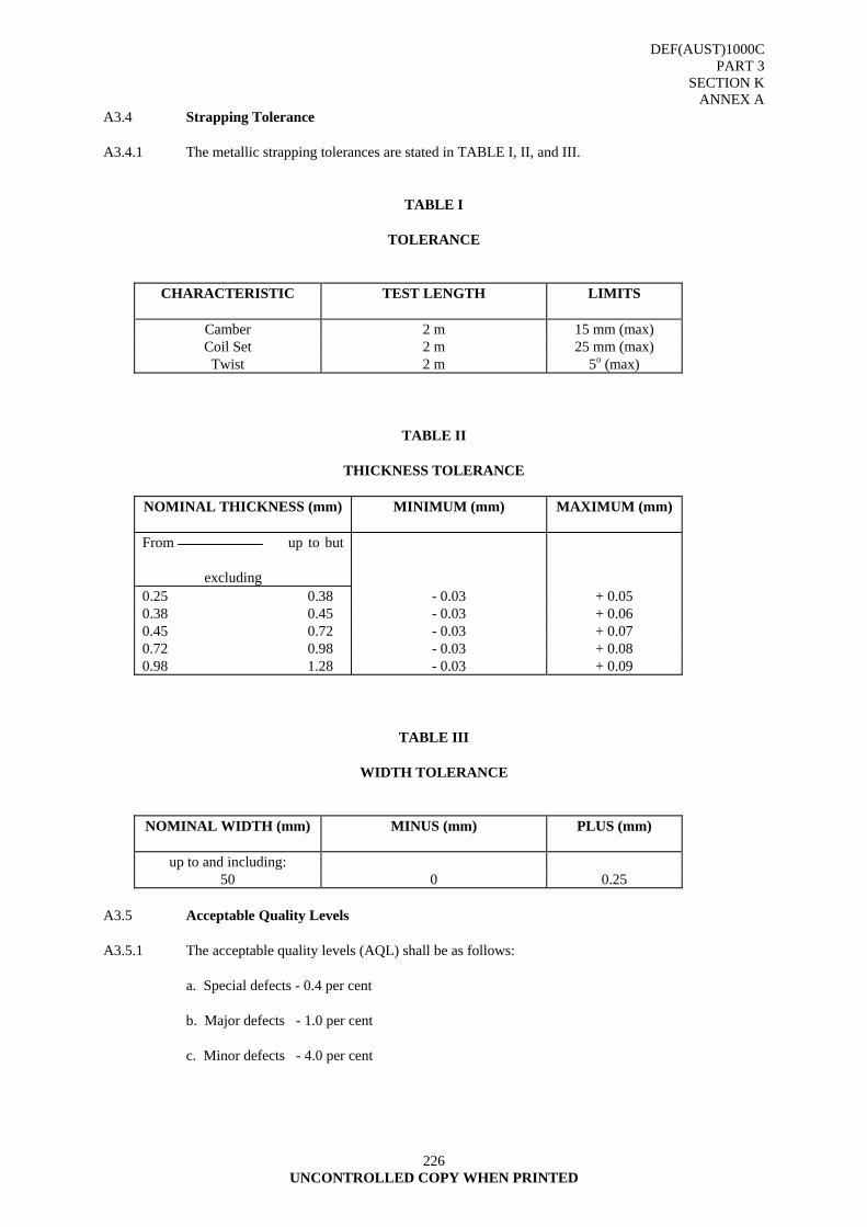
DEF(AUST)1000C PART 3
SECTION K ANNEX A
226 UNCONTROLLED COPY WHEN PRINTED
A3.4 Strapping Tolerance A3.4.1 The metallic strapping tolerances are stated in TABLE I, II, and III.
TABLE I
TOLERANCE
CHARACTERISTIC TEST LENGTH LIMITS
Camber 2 m 15 mm (max) Coil Set 2 m 25 mm (max) Twist 2 m 5o (max)
TABLE II
THICKNESS TOLERANCE
NOMINAL THICKNESS (mm) MINIMUM (mm) MAXIMUM (mm)
From up to but excluding
0.25 0.38 - 0.03 + 0.05 0.38 0.45 - 0.03 + 0.06 0.45 0.72 - 0.03 + 0.07 0.72 0.98 - 0.03 + 0.08 0.98 1.28 - 0.03 + 0.09
TABLE III
WIDTH TOLERANCE
NOMINAL WIDTH (mm) MINUS (mm) PLUS (mm)
up to and including: 50 0 0.25
A3.5 Acceptable Quality Levels A3.5.1 The acceptable quality levels (AQL) shall be as follows: a. Special defects - 0.4 per cent b. Major defects - 1.0 per cent c. Minor defects - 4.0 per cent
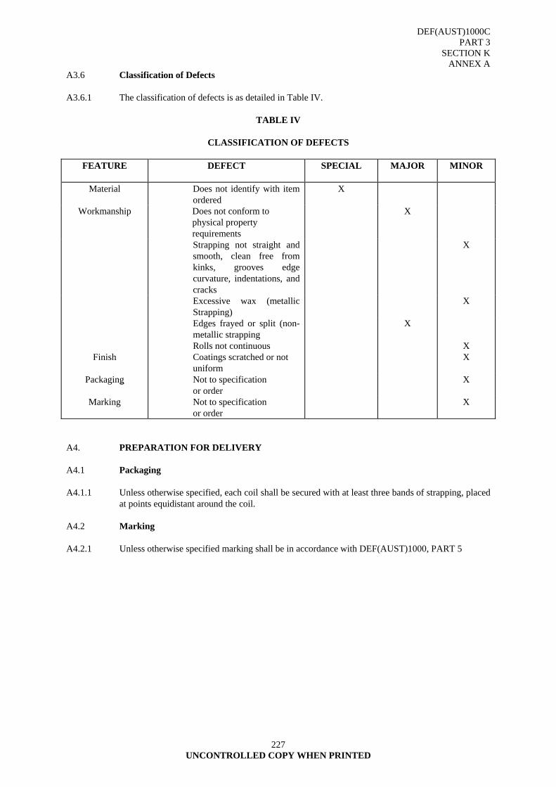
DEF(AUST)1000C PART 3
SECTION K ANNEX A
227 UNCONTROLLED COPY WHEN PRINTED
A3.6 Classification of Defects A3.6.1 The classification of defects is as detailed in Table IV.
TABLE IV
CLASSIFICATION OF DEFECTS
FEATURE DEFECT SPECIAL MAJOR MINOR
Material Does not identify with item ordered
X
Workmanship Does not conform to physical property requirements
X
Strapping not straight and smooth, clean free from kinks, grooves edge curvature, indentations, and cracks
X
Excessive wax (metallic Strapping)
X
Edges frayed or split (non-metallic strapping
X
Rolls not continuous X Finish Coatings scratched or not
uniform X
Packaging Not to specification or order
X
Marking Not to specification or order
X
A4. PREPARATION FOR DELIVERY A4.1 Packaging A4.1.1 Unless otherwise specified, each coil shall be secured with at least three bands of strapping, placed
at points equidistant around the coil. A4.2 Marking A4.2.1 Unless otherwise specified marking shall be in accordance with DEF(AUST)1000, PART 5
DEF(AUST)1000C PART 3
SECTION K ANNEX A
APPENDIX 1
228 UNCONTROLLED COPY WHEN PRINTED
APPENDIX 1
DUCTILITY OF METALLIC STRAPPING 1. PRINCIPLE 1.1 To measure the ductility and durability of metallic strapping. 2. PREPARATION 2.1 One or more samples of strapping shall be cut to suitable length so that they can be clamped in a
vice and bent by hand or mechanical means. 2.2 The strapping edges shall not be removed for the ductility test as this will remove the presence of
cold working or other deformation which may be introduced in the manufacturing process and which would normally be present when the strapping enters service.
3. PROCEDURE 3.1 The coil sample piece shall be clamped in a vice and bent by hand or mechanical means over a
radius of 3.5 + 0.5 mm a sufficient number of times to comply with TABLE II of the relevant Data Sheet.
3.2 One bend shall consist of a 90 degree bend and returned to the original position. Alternate bends
should be made in opposite directions. 4. EXPRESSION OF RESULTS 4.1 Report as conforms if the sample piece conforms to TABLE II of the relevant Data Sheet. 4.2 Report as does not conform and the nature of the non-conformity, if the strapping does not
conform to the relevant Data Sheet.
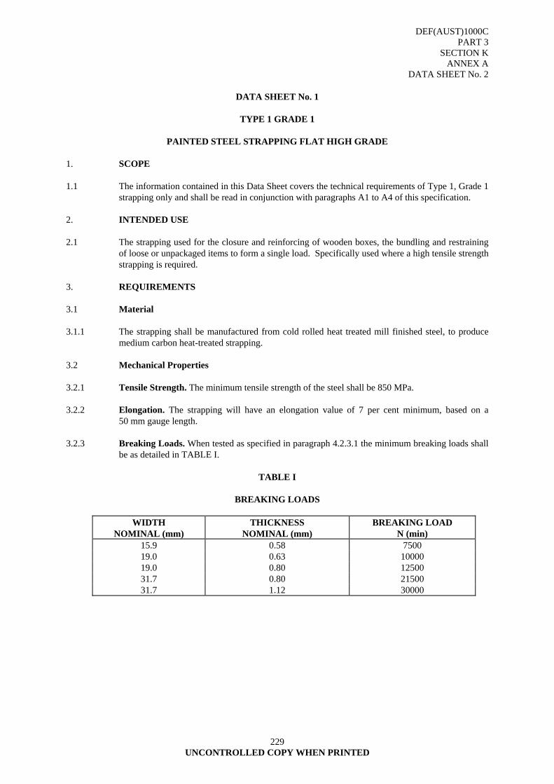
DEF(AUST)1000C PART 3
SECTION K ANNEX A
DATA SHEET No. 2
229 UNCONTROLLED COPY WHEN PRINTED
DATA SHEET No. 1
TYPE 1 GRADE 1
PAINTED STEEL STRAPPING FLAT HIGH GRADE
1. SCOPE 1.1 The information contained in this Data Sheet covers the technical requirements of Type 1, Grade 1
strapping only and shall be read in conjunction with paragraphs A1 to A4 of this specification. 2. INTENDED USE 2.1 The strapping used for the closure and reinforcing of wooden boxes, the bundling and restraining
of loose or unpackaged items to form a single load. Specifically used where a high tensile strength strapping is required.
3. REQUIREMENTS 3.1 Material 3.1.1 The strapping shall be manufactured from cold rolled heat treated mill finished steel, to produce
medium carbon heat-treated strapping. 3.2 Mechanical Properties 3.2.1 Tensile Strength. The minimum tensile strength of the steel shall be 850 MPa. 3.2.2 Elongation. The strapping will have an elongation value of 7 per cent minimum, based on a
50 mm gauge length. 3.2.3 Breaking Loads. When tested as specified in paragraph 4.2.3.1 the minimum breaking loads shall
be as detailed in TABLE I.
TABLE I
BREAKING LOADS
WIDTH NOMINAL (mm)
THICKNESS NOMINAL (mm)
BREAKING LOAD N (min)
15.9 0.58 7500 19.0 0.63 10000 19.0 0.80 12500 31.7 0.80 21500 31.7 1.12 30000
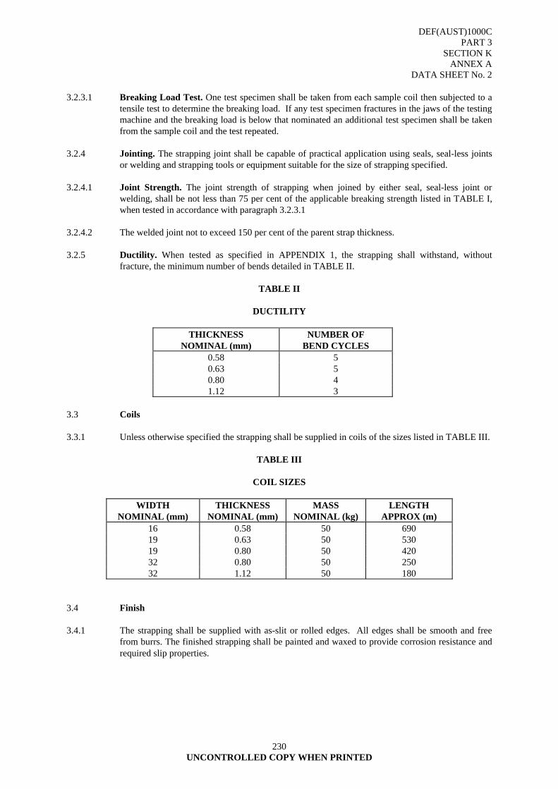
DEF(AUST)1000C PART 3
SECTION K ANNEX A
DATA SHEET No. 2
230 UNCONTROLLED COPY WHEN PRINTED
3.2.3.1 Breaking Load Test. One test specimen shall be taken from each sample coil then subjected to a
tensile test to determine the breaking load. If any test specimen fractures in the jaws of the testing machine and the breaking load is below that nominated an additional test specimen shall be taken from the sample coil and the test repeated.
3.2.4 Jointing. The strapping joint shall be capable of practical application using seals, seal-less joints
or welding and strapping tools or equipment suitable for the size of strapping specified. 3.2.4.1 Joint Strength. The joint strength of strapping when joined by either seal, seal-less joint or
welding, shall be not less than 75 per cent of the applicable breaking strength listed in TABLE I, when tested in accordance with paragraph 3.2.3.1
3.2.4.2 The welded joint not to exceed 150 per cent of the parent strap thickness. 3.2.5 Ductility. When tested as specified in APPENDIX 1, the strapping shall withstand, without
fracture, the minimum number of bends detailed in TABLE II.
TABLE II
DUCTILITY
THICKNESS NOMINAL (mm)
NUMBER OF BEND CYCLES
0.58 5 0.63 5 0.80 4 1.12 3
3.3 Coils 3.3.1 Unless otherwise specified the strapping shall be supplied in coils of the sizes listed in TABLE III.
TABLE III
COIL SIZES
WIDTH NOMINAL (mm)
THICKNESS NOMINAL (mm)
MASS NOMINAL (kg)
LENGTH APPROX (m)
16 0.58 50 690 19 0.63 50 530 19 0.80 50 420 32 0.80 50 250 32 1.12 50 180
3.4 Finish 3.4.1 The strapping shall be supplied with as-slit or rolled edges. All edges shall be smooth and free
from burrs. The finished strapping shall be painted and waxed to provide corrosion resistance and required slip properties.
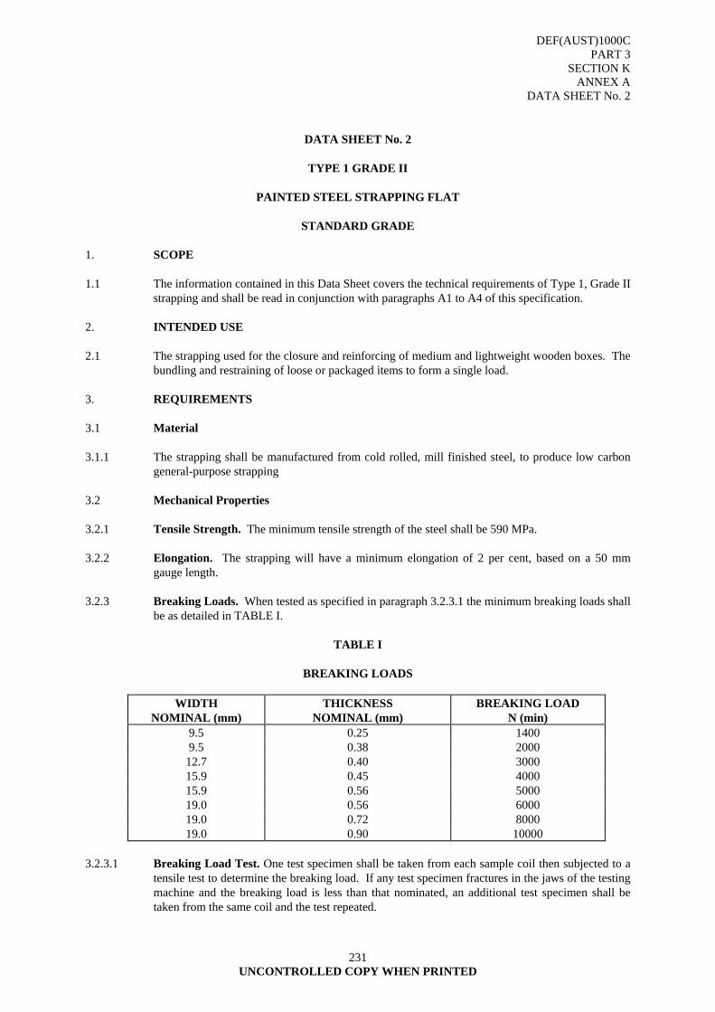
DEF(AUST)1000C PART 3
SECTION K ANNEX A
DATA SHEET No. 2
231 UNCONTROLLED COPY WHEN PRINTED
DATA SHEET No. 2
TYPE 1 GRADE II
PAINTED STEEL STRAPPING FLAT
STANDARD GRADE 1. SCOPE 1.1 The information contained in this Data Sheet covers the technical requirements of Type 1, Grade II
strapping and shall be read in conjunction with paragraphs A1 to A4 of this specification. 2. INTENDED USE 2.1 The strapping used for the closure and reinforcing of medium and lightweight wooden boxes. The
bundling and restraining of loose or packaged items to form a single load. 3. REQUIREMENTS 3.1 Material 3.1.1 The strapping shall be manufactured from cold rolled, mill finished steel, to produce low carbon
general-purpose strapping 3.2 Mechanical Properties 3.2.1 Tensile Strength. The minimum tensile strength of the steel shall be 590 MPa. 3.2.2 Elongation. The strapping will have a minimum elongation of 2 per cent, based on a 50 mm
gauge length. 3.2.3 Breaking Loads. When tested as specified in paragraph 3.2.3.1 the minimum breaking loads shall
be as detailed in TABLE I.
TABLE I
BREAKING LOADS
WIDTH NOMINAL (mm)
THICKNESS NOMINAL (mm)
BREAKING LOAD N (min)
9.5 0.25 1400 9.5 0.38 2000
12.7 0.40 3000 15.9 0.45 4000 15.9 0.56 5000 19.0 0.56 6000 19.0 0.72 8000 19.0 0.90 10000
3.2.3.1 Breaking Load Test. One test specimen shall be taken from each sample coil then subjected to a
tensile test to determine the breaking load. If any test specimen fractures in the jaws of the testing machine and the breaking load is less than that nominated, an additional test specimen shall be taken from the same coil and the test repeated.
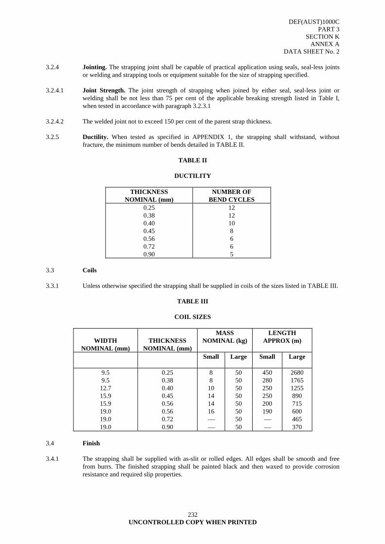
DEF(AUST)1000C PART 3
SECTION K ANNEX A
DATA SHEET No. 2
232 UNCONTROLLED COPY WHEN PRINTED
3.2.4 Jointing. The strapping joint shall be capable of practical application using seals, seal-less joints
or welding and strapping tools or equipment suitable for the size of strapping specified. 3.2.4.1 Joint Strength. The joint strength of strapping when joined by either seal, seal-less joint or
welding shall be not less than 75 per cent of the applicable breaking strength listed in Table I, when tested in accordance with paragraph 3.2.3.1
3.2.4.2 The welded joint not to exceed 150 per cent of the parent strap thickness. 3.2.5 Ductility. When tested as specified in APPENDIX 1, the strapping shall withstand, without
fracture, the minimum number of bends detailed in TABLE II.
TABLE II
DUCTILITY
THICKNESS NOMINAL (mm)
NUMBER OF BEND CYCLES
0.25 12 0.38 12 0.40 10 0.45 8 0.56 6 0.72 6 0.90 5
3.3 Coils 3.3.1 Unless otherwise specified the strapping shall be supplied in coils of the sizes listed in TABLE III.
TABLE III
COIL SIZES
WIDTH
NOMINAL (mm)
THICKNESS
NOMINAL (mm)
MASS NOMINAL (kg)
LENGTH APPROX (m)
Small Large Small Large
9.5 0.25 8 50 450 2680 9.5 0.38 8 50 280 1765
12.7 0.40 10 50 250 1255 15.9 0.45 14 50 250 890 15.9 0.56 14 50 200 715 19.0 0.56 16 50 190 600 19.0 0.72 ⎯ 50 ⎯ 465 19.0 0.90 ⎯ 50 ⎯ 370
3.4 Finish 3.4.1 The strapping shall be supplied with as-slit or rolled edges. All edges shall be smooth and free
from burrs. The finished strapping shall be painted black and then waxed to provide corrosion resistance and required slip properties.
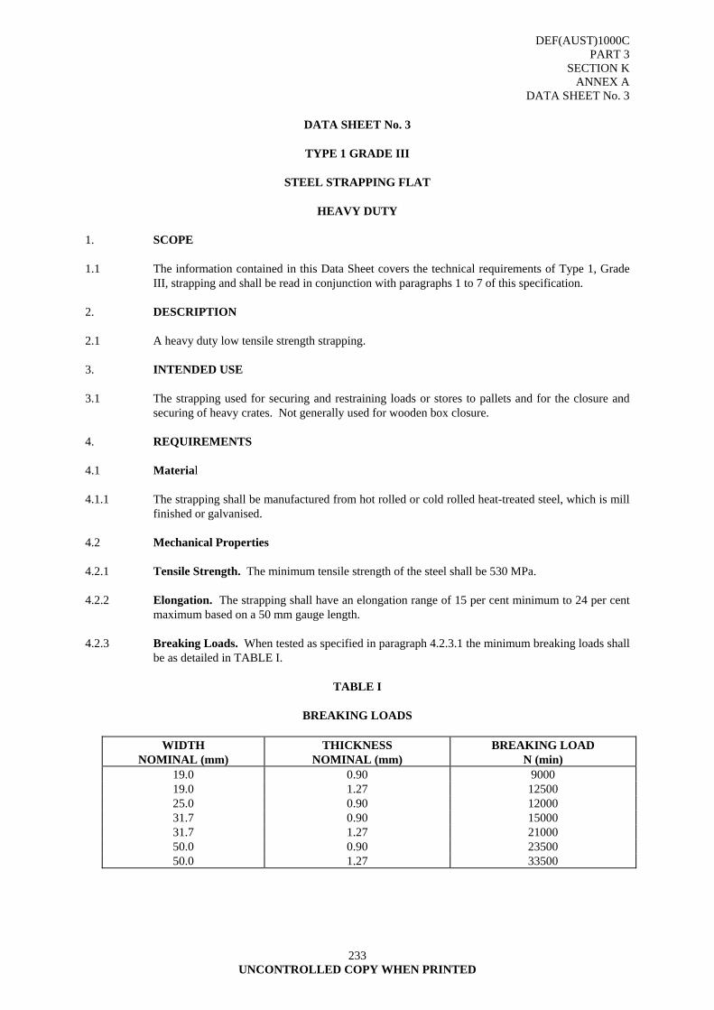
DEF(AUST)1000C PART 3
SECTION K ANNEX A
DATA SHEET No. 3
233 UNCONTROLLED COPY WHEN PRINTED
DATA SHEET No. 3
TYPE 1 GRADE III
STEEL STRAPPING FLAT
HEAVY DUTY
1. SCOPE 1.1 The information contained in this Data Sheet covers the technical requirements of Type 1, Grade
III, strapping and shall be read in conjunction with paragraphs 1 to 7 of this specification. 2. DESCRIPTION 2.1 A heavy duty low tensile strength strapping. 3. INTENDED USE 3.1 The strapping used for securing and restraining loads or stores to pallets and for the closure and
securing of heavy crates. Not generally used for wooden box closure. 4. REQUIREMENTS 4.1 Material 4.1.1 The strapping shall be manufactured from hot rolled or cold rolled heat-treated steel, which is mill
finished or galvanised. 4.2 Mechanical Properties 4.2.1 Tensile Strength. The minimum tensile strength of the steel shall be 530 MPa. 4.2.2 Elongation. The strapping shall have an elongation range of 15 per cent minimum to 24 per cent
maximum based on a 50 mm gauge length. 4.2.3 Breaking Loads. When tested as specified in paragraph 4.2.3.1 the minimum breaking loads shall
be as detailed in TABLE I.
TABLE I
BREAKING LOADS
WIDTH NOMINAL (mm)
THICKNESS NOMINAL (mm)
BREAKING LOAD N (min)
19.0 0.90 9000 19.0 1.27 12500 25.0 0.90 12000 31.7 0.90 15000 31.7 1.27 21000 50.0 0.90 23500 50.0 1.27 33500
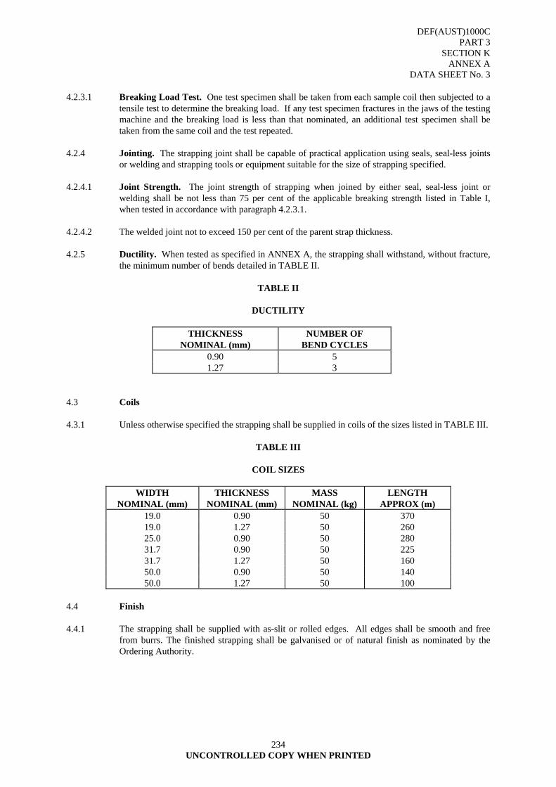
DEF(AUST)1000C PART 3
SECTION K ANNEX A
DATA SHEET No. 3
234 UNCONTROLLED COPY WHEN PRINTED
4.2.3.1 Breaking Load Test. One test specimen shall be taken from each sample coil then subjected to a
tensile test to determine the breaking load. If any test specimen fractures in the jaws of the testing machine and the breaking load is less than that nominated, an additional test specimen shall be taken from the same coil and the test repeated.
4.2.4 Jointing. The strapping joint shall be capable of practical application using seals, seal-less joints
or welding and strapping tools or equipment suitable for the size of strapping specified. 4.2.4.1 Joint Strength. The joint strength of strapping when joined by either seal, seal-less joint or
welding shall be not less than 75 per cent of the applicable breaking strength listed in Table I, when tested in accordance with paragraph 4.2.3.1.
4.2.4.2 The welded joint not to exceed 150 per cent of the parent strap thickness. 4.2.5 Ductility. When tested as specified in ANNEX A, the strapping shall withstand, without fracture,
the minimum number of bends detailed in TABLE II.
TABLE II
DUCTILITY
THICKNESS NOMINAL (mm)
NUMBER OF BEND CYCLES
0.90 5 1.27 3
4.3 Coils 4.3.1 Unless otherwise specified the strapping shall be supplied in coils of the sizes listed in TABLE III.
TABLE III
COIL SIZES
WIDTH NOMINAL (mm)
THICKNESS NOMINAL (mm)
MASS NOMINAL (kg)
LENGTH APPROX (m)
19.0 0.90 50 370 19.0 1.27 50 260 25.0 0.90 50 280 31.7 0.90 50 225 31.7 1.27 50 160 50.0 0.90 50 140 50.0 1.27 50 100
4.4 Finish 4.4.1 The strapping shall be supplied with as-slit or rolled edges. All edges shall be smooth and free
from burrs. The finished strapping shall be galvanised or of natural finish as nominated by the Ordering Authority.
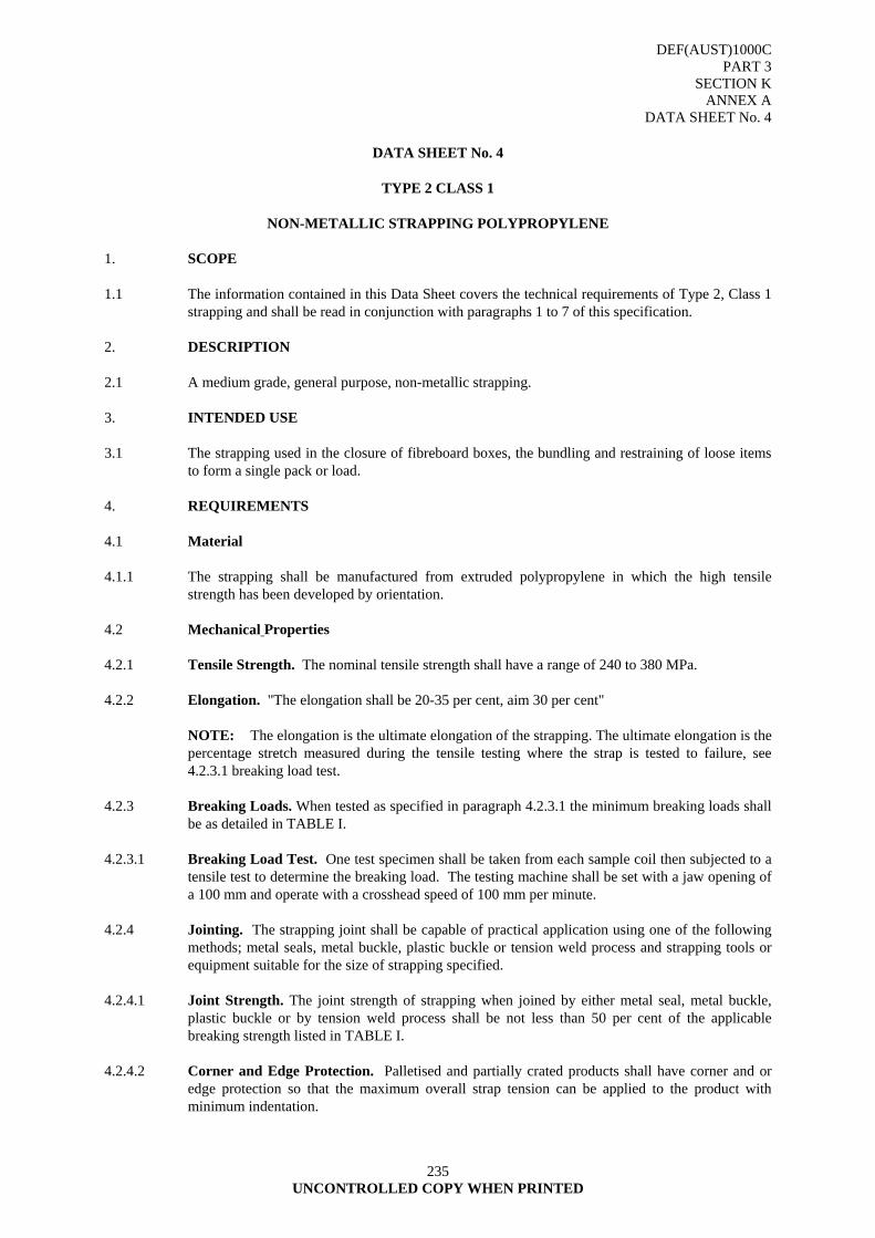
DEF(AUST)1000C PART 3
SECTION K ANNEX A
DATA SHEET No. 4
235 UNCONTROLLED COPY WHEN PRINTED
DATA SHEET No. 4
TYPE 2 CLASS 1
NON-METALLIC STRAPPING POLYPROPYLENE
1. SCOPE 1.1 The information contained in this Data Sheet covers the technical requirements of Type 2, Class 1
strapping and shall be read in conjunction with paragraphs 1 to 7 of this specification. 2. DESCRIPTION 2.1 A medium grade, general purpose, non-metallic strapping. 3. INTENDED USE 3.1 The strapping used in the closure of fibreboard boxes, the bundling and restraining of loose items
to form a single pack or load. 4. REQUIREMENTS 4.1 Material 4.1.1 The strapping shall be manufactured from extruded polypropylene in which the high tensile
strength has been developed by orientation. 4.2 Mechanical Properties 4.2.1 Tensile Strength. The nominal tensile strength shall have a range of 240 to 380 MPa. 4.2.2 Elongation. "The elongation shall be 20-35 per cent, aim 30 per cent" NOTE: The elongation is the ultimate elongation of the strapping. The ultimate elongation is the
percentage stretch measured during the tensile testing where the strap is tested to failure, see 4.2.3.1 breaking load test.
4.2.3 Breaking Loads. When tested as specified in paragraph 4.2.3.1 the minimum breaking loads shall
be as detailed in TABLE I. 4.2.3.1 Breaking Load Test. One test specimen shall be taken from each sample coil then subjected to a
tensile test to determine the breaking load. The testing machine shall be set with a jaw opening of a 100 mm and operate with a crosshead speed of 100 mm per minute.
4.2.4 Jointing. The strapping joint shall be capable of practical application using one of the following
methods; metal seals, metal buckle, plastic buckle or tension weld process and strapping tools or equipment suitable for the size of strapping specified.
4.2.4.1 Joint Strength. The joint strength of strapping when joined by either metal seal, metal buckle,
plastic buckle or by tension weld process shall be not less than 50 per cent of the applicable breaking strength listed in TABLE I.
4.2.4.2 Corner and Edge Protection. Palletised and partially crated products shall have corner and or
edge protection so that the maximum overall strap tension can be applied to the product with minimum indentation.
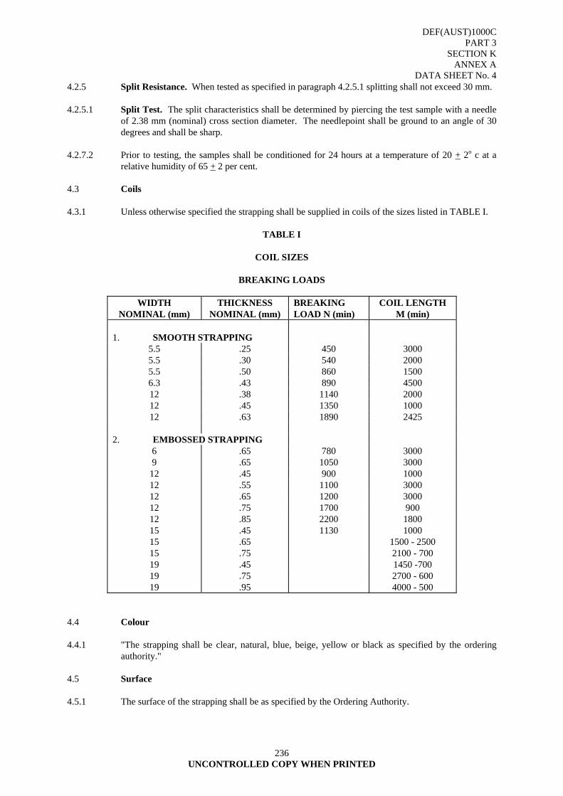
DEF(AUST)1000C PART 3
SECTION K ANNEX A
DATA SHEET No. 4
236 UNCONTROLLED COPY WHEN PRINTED
4.2.5 Split Resistance. When tested as specified in paragraph 4.2.5.1 splitting shall not exceed 30 mm. 4.2.5.1 Split Test. The split characteristics shall be determined by piercing the test sample with a needle
of 2.38 mm (nominal) cross section diameter. The needlepoint shall be ground to an angle of 30 degrees and shall be sharp.
4.2.7.2 Prior to testing, the samples shall be conditioned for 24 hours at a temperature of 20 + 2o c at a
relative humidity of 65 + 2 per cent. 4.3 Coils 4.3.1 Unless otherwise specified the strapping shall be supplied in coils of the sizes listed in TABLE I.
TABLE I
COIL SIZES
BREAKING LOADS
WIDTH NOMINAL (mm)
THICKNESS NOMINAL (mm)
BREAKING LOAD N (min)
COIL LENGTH M (min)
1. SMOOTH STRAPPING
5.5 .25 450 3000 5.5 .30 540 2000 5.5 .50 860 1500 6.3 .43 890 4500 12 .38 1140 2000 12 .45 1350 1000 12 .63 1890 2425
2. EMBOSSED STRAPPING
6 .65 780 3000 9 .65 1050 3000
12 .45 900 1000 12 .55 1100 3000 12 .65 1200 3000 12 .75 1700 900 12 .85 2200 1800 15 .45 1130 1000 15 .65 1500 - 2500 15 .75 2100 - 700 19 .45 1450 -700 19 .75 2700 - 600 19 .95 4000 - 500
4.4 Colour 4.4.1 "The strapping shall be clear, natural, blue, beige, yellow or black as specified by the ordering
authority." 4.5 Surface 4.5.1 The surface of the strapping shall be as specified by the Ordering Authority.
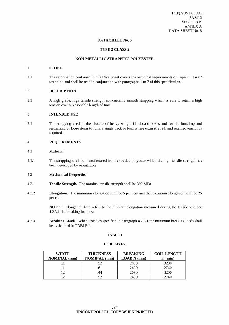
DEF(AUST)1000C PART 3
SECTION K ANNEX A
DATA SHEET No. 5
237 UNCONTROLLED COPY WHEN PRINTED
DATA SHEET No. 5
TYPE 2 CLASS 2
NON-METALLIC STRAPPING POLYESTER
1. SCOPE 1.1 The information contained in this Data Sheet covers the technical requirements of Type 2, Class 2
strapping and shall be read in conjunction with paragraphs 1 to 7 of this specification. 2. DESCRIPTION 2.1 A high grade, high tensile strength non-metallic smooth strapping which is able to retain a high
tension over a reasonable length of time. 3. INTENDED USE 3.1 The strapping used in the closure of heavy weight fibreboard boxes and for the bundling and
restraining of loose items to form a single pack or load where extra strength and retained tension is required.
4. REQUIREMENTS 4.1 Material 4.1.1 The strapping shall be manufactured from extruded polyester which the high tensile strength has
been developed by orientation. 4.2 Mechanical Properties 4.2.1 Tensile Strength. The nominal tensile strength shall be 390 MPa. 4.2.2 Elongation. The minimum elongation shall be 5 per cent and the maximum elongation shall be 25
per cent. NOTE: Elongation here refers to the ultimate elongation measured during the tensile test, see
4.2.3.1 the breaking load test. 4.2.3 Breaking Loads. When tested as specified in paragraph 4.2.3.1 the minimum breaking loads shall
be as detailed in TABLE I.
TABLE I
COIL SIZES
WIDTH NOMINAL (mm)
THICKNESS NOMINAL (mm)
BREAKING LOAD N (min)
COIL LENGTH m (min)
11 .52 2050 3200 11 .61 2490 2740 12 .44 2090 3200 12 .52 2490 2740
DEF(AUST)1000C PART 3
SECTION K ANNEX A
DATA SHEET No. 5
238 UNCONTROLLED COPY WHEN PRINTED
4.2.3.1 Breaking Load Test. One test specimen shall be taken from each sample coil and shall be subjected to a tensile test to determine the breaking load. The testing machine shall be set with a jaw opening of a 100 mm and operate with a crosshead speed of 100 mm per minute.
4.2.4 Jointing. The strapping joint shall be capable of practical application using one of the following
metal seals, metal buckle, plastic buckle or tension weld process and strapping tools or equipment suitable for the size of strapping specified.
4.2.4.1 Joint Strength. The joint strength of the strapping when joined by either metal seals, metal
buckle, plastic buckle or by tension weld process shall be not less than 60 per cent of the applicable breaking strength listed in TABLE I.
4.2.4.2 Corner and Edge Protection. Palletised and partially crated products shall have corner and or
edge protection so that the maximum overall strap tension can be applied to the product with the minimum indentation.
4.2.5 Splitting Resistance. When tested as specified in paragraph 4.2.5.1 splitting shall not exceed
10 mm. 4.2.5.1 Split Test. The characteristic shall be determined by piercing the test sample with a needle of
2.38 mm nominal cross section diameter. The needlepoint shall be ground to an angle of 30 degrees and shall be sharp.
4.3 Coils 4.3.1 Unless otherwise specified, the strapping shall be supplied in coils of the sizes listed in TABLE I. 4.4 Colour 4.4.1 The strapping shall be white or turquoise colour.
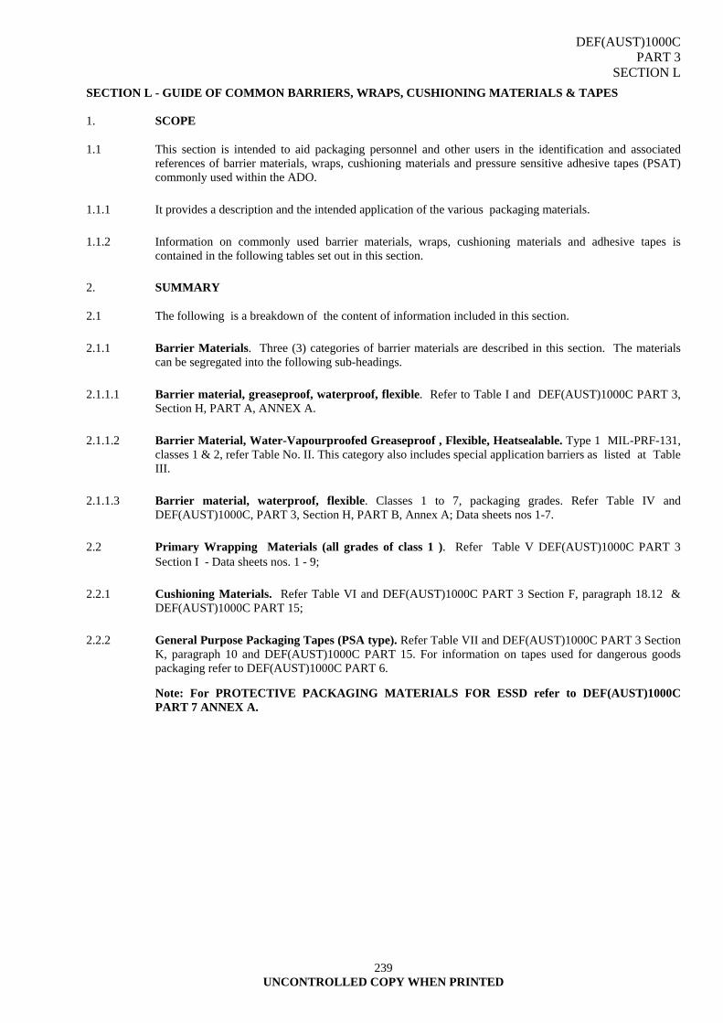
DEF(AUST)1000C PART 3
SECTION L
239 UNCONTROLLED COPY WHEN PRINTED
SECTION L - GUIDE OF COMMON BARRIERS, WRAPS, CUSHIONING MATERIALS & TAPES
1. SCOPE
1.1 This section is intended to aid packaging personnel and other users in the identification and associated references of barrier materials, wraps, cushioning materials and pressure sensitive adhesive tapes (PSAT) commonly used within the ADO.
1.1.1 It provides a description and the intended application of the various packaging materials.
1.1.2 Information on commonly used barrier materials, wraps, cushioning materials and adhesive tapes is contained in the following tables set out in this section.
2. SUMMARY
2.1 The following is a breakdown of the content of information included in this section.
2.1.1 Barrier Materials. Three (3) categories of barrier materials are described in this section. The materials can be segregated into the following sub-headings.
2.1.1.1 Barrier material, greaseproof, waterproof, flexible. Refer to Table I and DEF(AUST)1000C PART 3, Section H, PART A, ANNEX A.
2.1.1.2 Barrier Material, Water-Vapourproofed Greaseproof , Flexible, Heatsealable. Type 1 MIL-PRF-131, classes 1 & 2, refer Table No. II. This category also includes special application barriers as listed at Table III.
2.1.1.3 Barrier material, waterproof, flexible. Classes 1 to 7, packaging grades. Refer Table IV and DEF(AUST)1000C, PART 3, Section H, PART B, Annex A; Data sheets nos 1-7.
2.2 Primary Wrapping Materials (all grades of class 1 ). Refer Table V DEF(AUST)1000C PART 3 Section I - Data sheets nos. 1 - 9;
2.2.1 Cushioning Materials. Refer Table VI and DEF(AUST)1000C PART 3 Section F, paragraph 18.12 & DEF(AUST)1000C PART 15;
2.2.2 General Purpose Packaging Tapes (PSA type). Refer Table VII and DEF(AUST)1000C PART 3 Section K, paragraph 10 and DEF(AUST)1000C PART 15. For information on tapes used for dangerous goods packaging refer to DEF(AUST)1000C PART 6.
Note: For PROTECTIVE PACKAGING MATERIALS FOR ESSD refer to DEF(AUST)1000C PART 7 ANNEX A.
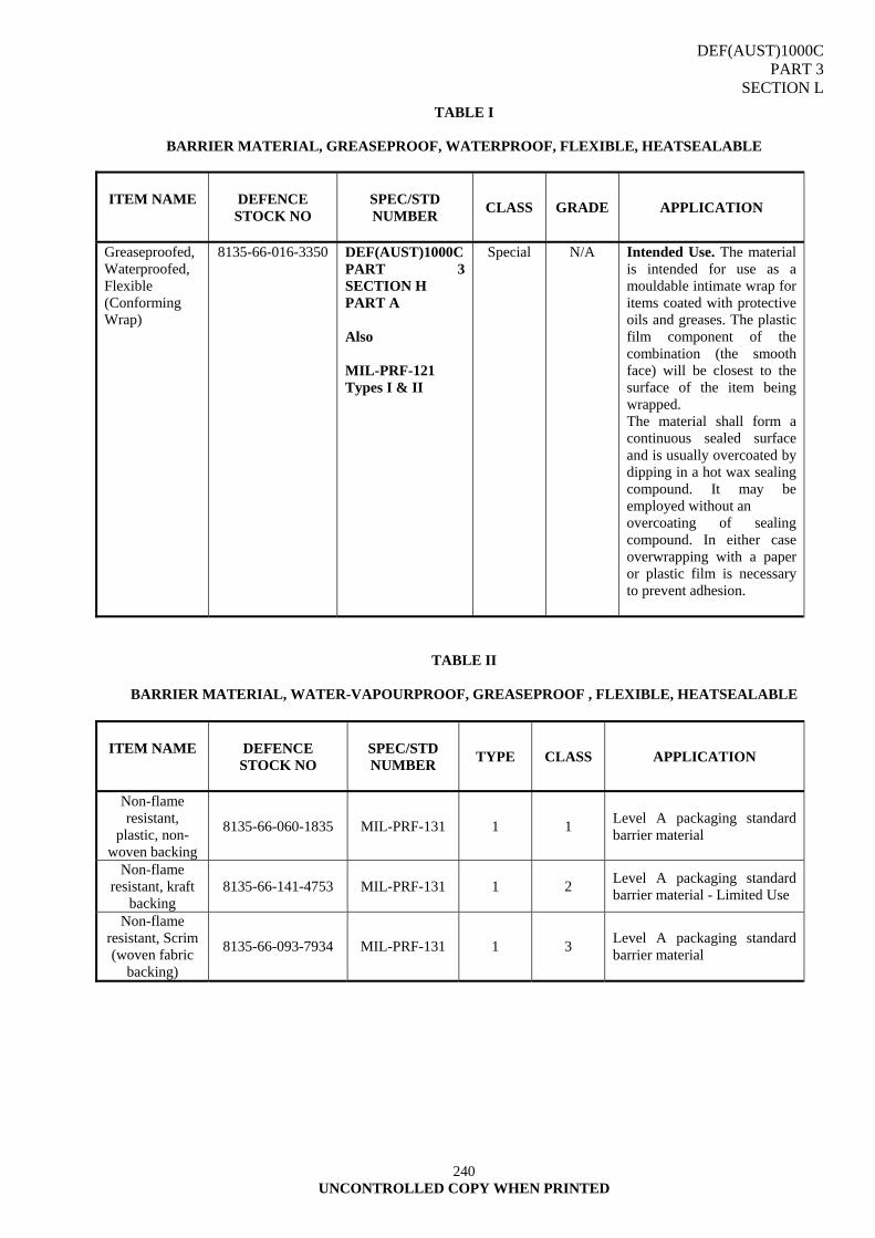
DEF(AUST)1000C PART 3
SECTION L
240 UNCONTROLLED COPY WHEN PRINTED
TABLE I
BARRIER MATERIAL, GREASEPROOF, WATERPROOF, FLEXIBLE, HEATSEALABLE
ITEM NAME
DEFENCE STOCK NO
SPEC/STD NUMBER CLASS GRADE
APPLICATION
Greaseproofed, Waterproofed, Flexible (Conforming Wrap)
8135-66-016-3350 DEF(AUST)1000C PART 3 SECTION H PART A Also MIL-PRF-121 Types I & II
Special N/A Intended Use. The material is intended for use as a mouldable intimate wrap for items coated with protective oils and greases. The plastic film component of the combination (the smooth face) will be closest to the surface of the item being wrapped. The material shall form a continuous sealed surface and is usually overcoated by dipping in a hot wax sealing compound. It may be employed without an overcoating of sealing compound. In either case overwrapping with a paper or plastic film is necessary to prevent adhesion.
TABLE II
BARRIER MATERIAL, WATER-VAPOURPROOF, GREASEPROOF , FLEXIBLE, HEATSEALABLE
ITEM NAME
DEFENCE STOCK NO
SPEC/STD NUMBER TYPE CLASS
APPLICATION
Non-flame resistant,
plastic, non-woven backing
8135-66-060-1835 MIL-PRF-131 1 1 Level A packaging standard barrier material
Non-flame resistant, kraft
backing 8135-66-141-4753 MIL-PRF-131 1 2 Level A packaging standard
barrier material - Limited Use
Non-flame resistant, Scrim (woven fabric
backing)
8135-66-093-7934 MIL-PRF-131 1 3 Level A packaging standard barrier material

DEF(AUST)1000C PART 3
SECTION L
241 UNCONTROLLED COPY WHEN PRINTED
TABLE III
BARRIER MATERIAL - SPECIAL APPLICATION
ITEM NAME
SPEC/STD NUMBER
APPLICATION
KNOWN
SUPPLIER
Vapour phase Corrosion Inhibitor (VCI) treated polyethylene film Ferrous and non-ferrous material applications
MIL-PRF-3420 Classes 1 - Heavy duty 2 - Medium duty 3 - Light duty
Used as a primary wrap for ferrous metals and provides good protection to areas of an item that would be impossible or impractical to apply a grease or oil type preservatiove. Also for clean dry, oil free corrosion protection as box liners and overwraps where a high strength heatsealable corrosion inhibitor is required, eg machine surfaces, weapon parts, vehicle repair parts and main supply items (MSIs). NOTE: Not to be used with foodstuffs.
Prestige Plastics Pty Ltd 22 Highwood Dve Glen waverley VIC Ph: (03) 9562 1606
eeled, Low Density, Polyethylene Film
For the manufacture of primary wraps in intimate contact with an item, also as bags, box liners and overwraps. This material provides a physical shield against the ingress of water, dust and dirt.
Exthene Pty Ltd 83 Keys Rd Moorabbin VIC Ph: (03) 9555 9666
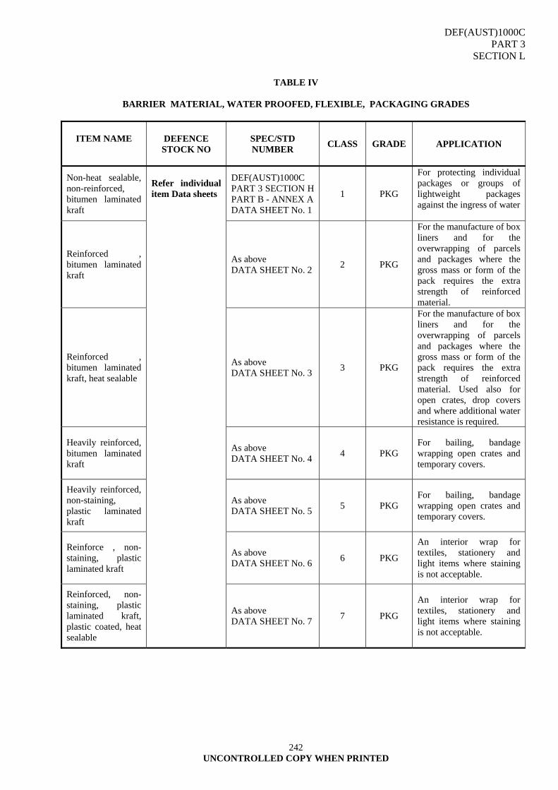
DEF(AUST)1000C PART 3
SECTION L
242 UNCONTROLLED COPY WHEN PRINTED
TABLE IV
BARRIER MATERIAL, WATER PROOFED, FLEXIBLE, PACKAGING GRADES
ITEM NAME
DEFENCE STOCK NO
SPEC/STD NUMBER CLASS GRADE
APPLICATION
Non-heat sealable, non-reinforced, bitumen laminated kraft
DEF(AUST)1000C PART 3 SECTION H PART B - ANNEX A DATA SHEET No. 1
1 PKG
For protecting individual packages or groups of lightweight packages against the ingress of water
Reinforced , bitumen laminated kraft
As above DATA SHEET No. 2 2 PKG
For the manufacture of box liners and for the overwrapping of parcels and packages where the gross mass or form of the pack requires the extra strength of reinforced material.
Reinforced , bitumen laminated kraft, heat sealable
As above DATA SHEET No. 3 3 PKG
For the manufacture of box liners and for the overwrapping of parcels and packages where the gross mass or form of the pack requires the extra strength of reinforced material. Used also for open crates, drop covers and where additional water resistance is required.
Heavily reinforced, bitumen laminated kraft
As above DATA SHEET No. 4 4 PKG
For bailing, bandage wrapping open crates and temporary covers.
Heavily reinforced, non-staining, plastic laminated kraft
As above DATA SHEET No. 5 5 PKG
For bailing, bandage wrapping open crates and temporary covers.
Reinforce , non-staining, plastic laminated kraft
As above DATA SHEET No. 6 6 PKG
An interior wrap for textiles, stationery and light items where staining is not acceptable.
Reinforced, non-staining, plastic laminated kraft, plastic coated, heat sealable
Refer individual item Data sheets
As above DATA SHEET No. 7 7 PKG
An interior wrap for textiles, stationery and light items where staining is not acceptable.
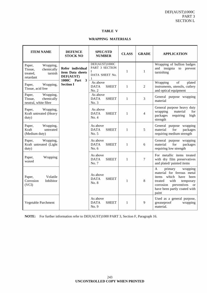
DEF(AUST)1000C PART 3
SECTION L
243 UNCONTROLLED COPY WHEN PRINTED
TABLE V
WRAPPING MATERIALS
ITEM NAME
DEFENCE STOCK NO
SPEC/STD NUMBER CLASS GRADE
APPLICATION
Paper, Wrapping, Tissue, chemically treated, tarnish retardant
DEF(AUST)1000C PART 3 SECTION I DATA SHEET No. 1
1 1
Wrapping of bullion badges and insignia to prevent tarnishing
Paper, Wrapping, Tissue, acid free
As above DATA SHEET No. 2
1 2 Wrapping of plated instruments, utensils, cutlery and optical equipment
Paper, Wrapping, Tissue, chemically neutral, white fibre
As above DATA SHEET No. 3
1 3 General purpose wrapping material
Paper, Wrapping, Kraft untreated (Heavy duty)
As above DATA SHEET No. 4
1 4
General purpose heavy duty wrapping material for packages requiring high strength
Paper, Wrapping, Kraft untreated (Medium duty)
As above DATA SHEET No. 5
1 5 General purpose wrapping material for packages requiring medium strength
Paper, Wrapping, Kraft untreated (Light duty)
As above DATA SHEET No. 6
1 6 General purpose wrapping material for packages requiring low strength
Paper, Wrapping waxed
As above DATA SHEET No. 7
1 7 For metallic items treated with dry film preservatives and plated/ painted items
Paper, Volatile Corrosion Inhibitor (VCI)
As above DATA SHEET No. 8
1 8
A primary wrapping material for ferrous metal items which have been treated with temporary corrosion preventives or have been partly coated with paint
Vegetable Parchment
Refer individual item Data sheets DEF(AUST) 1000C Part 3 Section I
As above DATA SHEET No. 9
1 9 Used as a general purpose, greaseproof wrapping material.
NOTE: For further information refer to DEF(AUST)1000 PART 3, Section F, Paragraph 16.
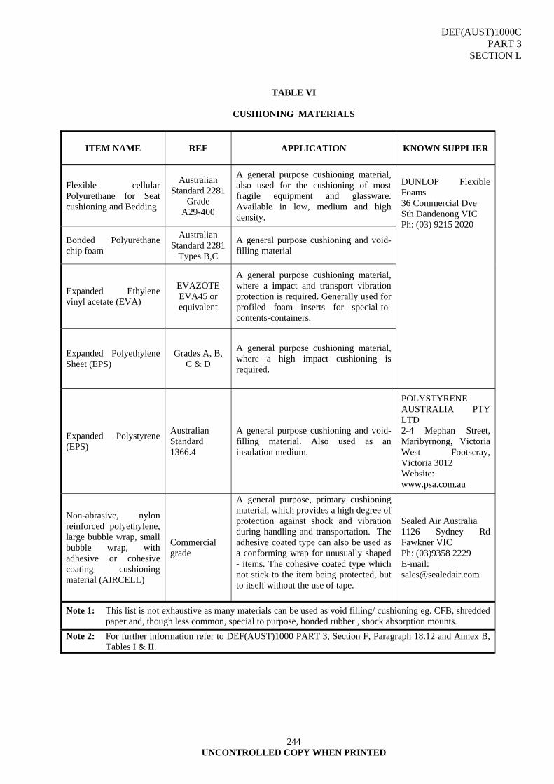
DEF(AUST)1000C PART 3
SECTION L
244 UNCONTROLLED COPY WHEN PRINTED
TABLE VI
CUSHIONING MATERIALS
ITEM NAME
REF
APPLICATION
KNOWN SUPPLIER
Flexible cellular Polyurethane for Seat cushioning and Bedding
Australian Standard 2281
Grade A29-400
A general purpose cushioning material, also used for the cushioning of most fragile equipment and glassware. Available in low, medium and high density.
Bonded Polyurethane chip foam
Australian Standard 2281
Types B,C
A general purpose cushioning and void-filling material
Expanded Ethylene vinyl acetate (EVA)
EVAZOTE EVA45 or equivalent
A general purpose cushioning material, where a impact and transport vibration protection is required. Generally used for profiled foam inserts for special-to-contents-containers.
Expanded Polyethylene Sheet (EPS)
Grades A, B, C & D
A general purpose cushioning material, where a high impact cushioning is required.
DUNLOP Flexible Foams 36 Commercial Dve Sth Dandenong VIC Ph: (03) 9215 2020
Expanded Polystyrene (EPS)
Australian Standard 1366.4
A general purpose cushioning and void-filling material. Also used as an insulation medium.
POLYSTYRENE AUSTRALIA PTY LTD 2-4 Mephan Street, Maribyrnong, Victoria West Footscray, Victoria 3012 Website: www.psa.com.au
Non-abrasive, nylon reinforced polyethylene, large bubble wrap, small bubble wrap, with adhesive or cohesive coating cushioning material (AIRCELL)
Commercial grade
A general purpose, primary cushioning material, which provides a high degree of protection against shock and vibration during handling and transportation. The adhesive coated type can also be used as a conforming wrap for unusually shaped - items. The cohesive coated type which not stick to the item being protected, but to itself without the use of tape.
Sealed Air Australia 1126 Sydney Rd Fawkner VIC Ph: (03)9358 2229 E-mail: [email protected]
Note 1: This list is not exhaustive as many materials can be used as void filling/ cushioning eg. CFB, shredded paper and, though less common, special to purpose, bonded rubber , shock absorption mounts.
Note 2: For further information refer to DEF(AUST)1000 PART 3, Section F, Paragraph 18.12 and Annex B, Tables I & II.
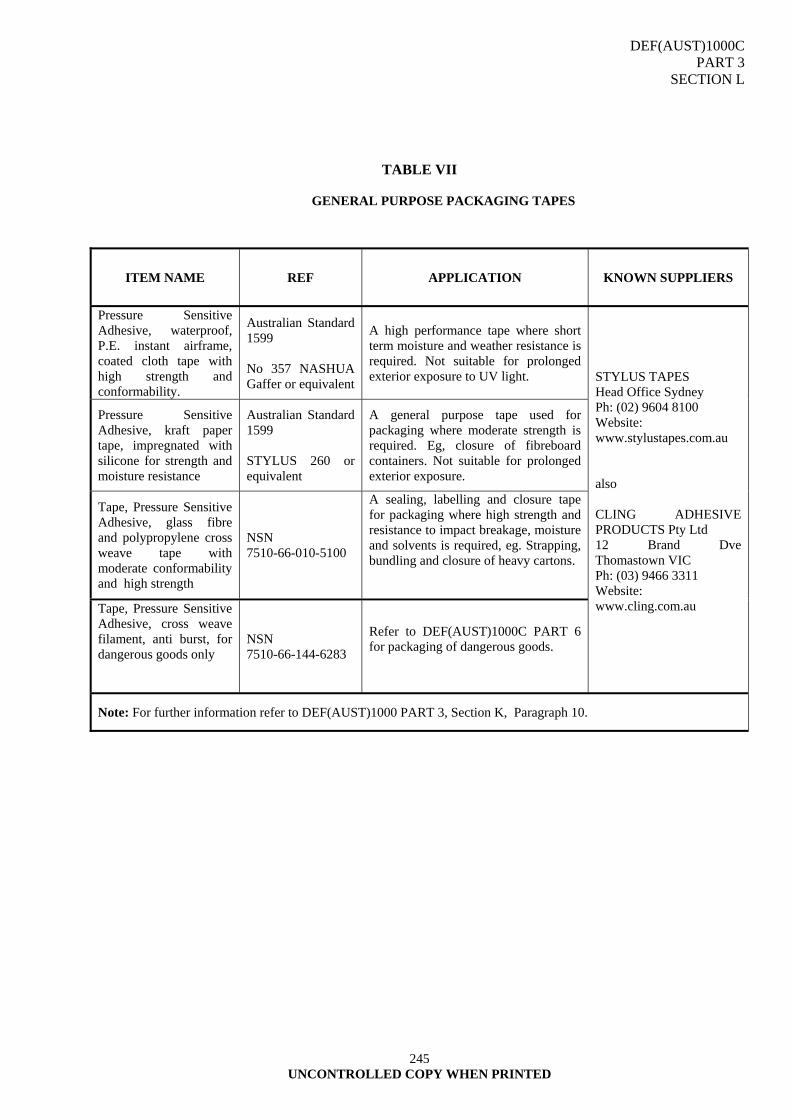
DEF(AUST)1000C PART 3
SECTION L
245 UNCONTROLLED COPY WHEN PRINTED
TABLE VII
GENERAL PURPOSE PACKAGING TAPES
ITEM NAME
REF
APPLICATION
KNOWN SUPPLIERS
Pressure Sensitive Adhesive, waterproof, P.E. instant airframe, coated cloth tape with high strength and conformability.
Australian Standard 1599 No 357 NASHUA Gaffer or equivalent
A high performance tape where short term moisture and weather resistance is required. Not suitable for prolonged exterior exposure to UV light.
Pressure Sensitive Adhesive, kraft paper tape, impregnated with silicone for strength and moisture resistance
Australian Standard 1599 STYLUS 260 or equivalent
A general purpose tape used for packaging where moderate strength is required. Eg, closure of fibreboard containers. Not suitable for prolonged exterior exposure.
Tape, Pressure Sensitive Adhesive, glass fibre and polypropylene cross weave tape with moderate conformability and high strength
NSN 7510-66-010-5100
A sealing, labelling and closure tape for packaging where high strength and resistance to impact breakage, moisture and solvents is required, eg. Strapping, bundling and closure of heavy cartons.
Tape, Pressure Sensitive Adhesive, cross weave filament, anti burst, for dangerous goods only
NSN 7510-66-144-6283
Refer to DEF(AUST)1000C PART 6 for packaging of dangerous goods.
STYLUS TAPES Head Office Sydney Ph: (02) 9604 8100 Website: www.stylustapes.com.au
also CLING ADHESIVE PRODUCTS Pty Ltd 12 Brand Dve Thomastown VIC Ph: (03) 9466 3311 Website: www.cling.com.au
Note: For further information refer to DEF(AUST)1000 PART 3, Section K, Paragraph 10.
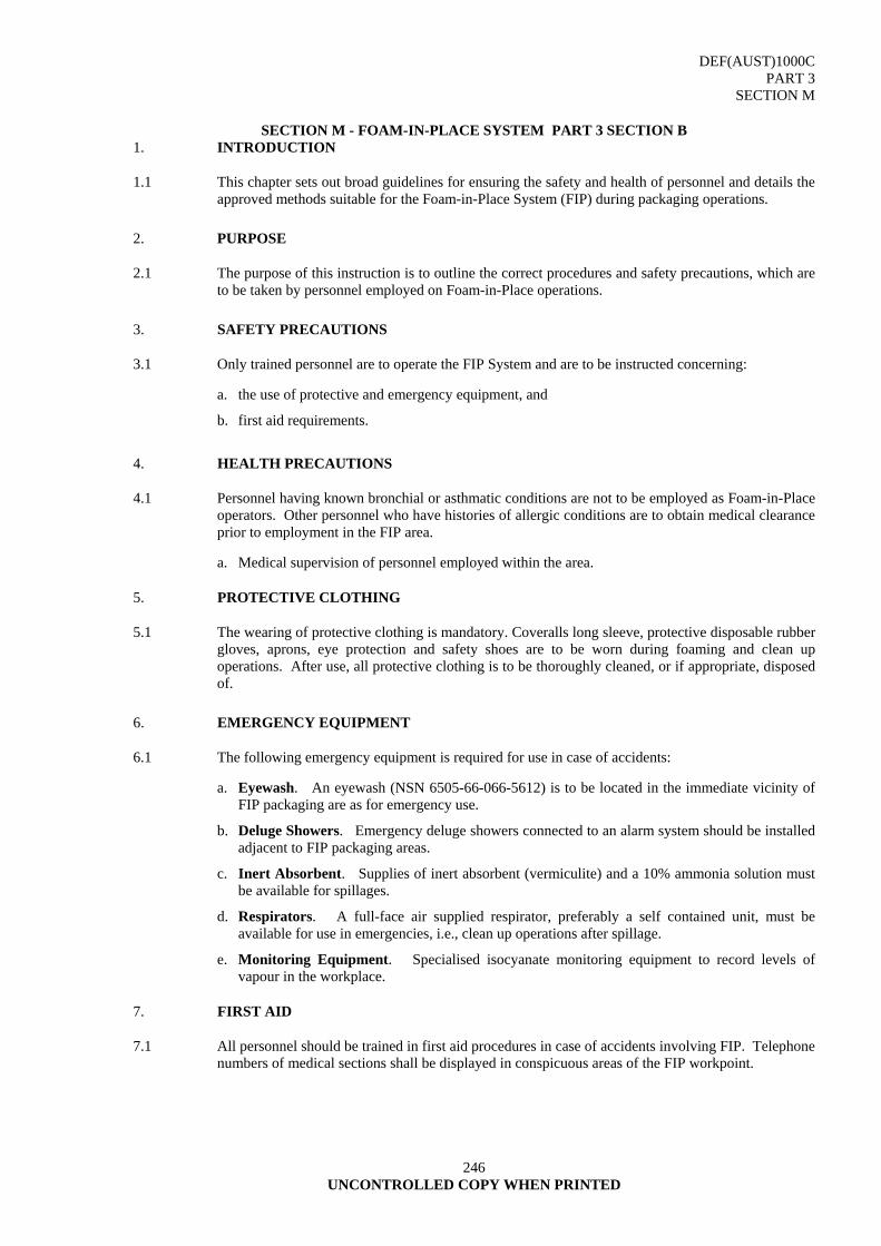
DEF(AUST)1000C PART 3
SECTION M
246 UNCONTROLLED COPY WHEN PRINTED
SECTION M - FOAM-IN-PLACE SYSTEM PART 3 SECTION B 1. INTRODUCTION
1.1 This chapter sets out broad guidelines for ensuring the safety and health of personnel and details the approved methods suitable for the Foam-in-Place System (FIP) during packaging operations.
2. PURPOSE
2.1 The purpose of this instruction is to outline the correct procedures and safety precautions, which are to be taken by personnel employed on Foam-in-Place operations.
3. SAFETY PRECAUTIONS
3.1 Only trained personnel are to operate the FIP System and are to be instructed concerning:
a. the use of protective and emergency equipment, and
b. first aid requirements.
4. HEALTH PRECAUTIONS
4.1 Personnel having known bronchial or asthmatic conditions are not to be employed as Foam-in-Place operators. Other personnel who have histories of allergic conditions are to obtain medical clearance prior to employment in the FIP area.
a. Medical supervision of personnel employed within the area. 5. PROTECTIVE CLOTHING
5.1 The wearing of protective clothing is mandatory. Coveralls long sleeve, protective disposable rubber gloves, aprons, eye protection and safety shoes are to be worn during foaming and clean up operations. After use, all protective clothing is to be thoroughly cleaned, or if appropriate, disposed of.
6. EMERGENCY EQUIPMENT
6.1 The following emergency equipment is required for use in case of accidents:
a. Eyewash. An eyewash (NSN 6505-66-066-5612) is to be located in the immediate vicinity of FIP packaging are as for emergency use.
b. Deluge Showers. Emergency deluge showers connected to an alarm system should be installed adjacent to FIP packaging areas.
c. Inert Absorbent. Supplies of inert absorbent (vermiculite) and a 10% ammonia solution must be available for spillages.
d. Respirators. A full-face air supplied respirator, preferably a self contained unit, must be available for use in emergencies, i.e., clean up operations after spillage.
e. Monitoring Equipment. Specialised isocyanate monitoring equipment to record levels of vapour in the workplace.
7. FIRST AID
7.1 All personnel should be trained in first aid procedures in case of accidents involving FIP. Telephone numbers of medical sections shall be displayed in conspicuous areas of the FIP workpoint.
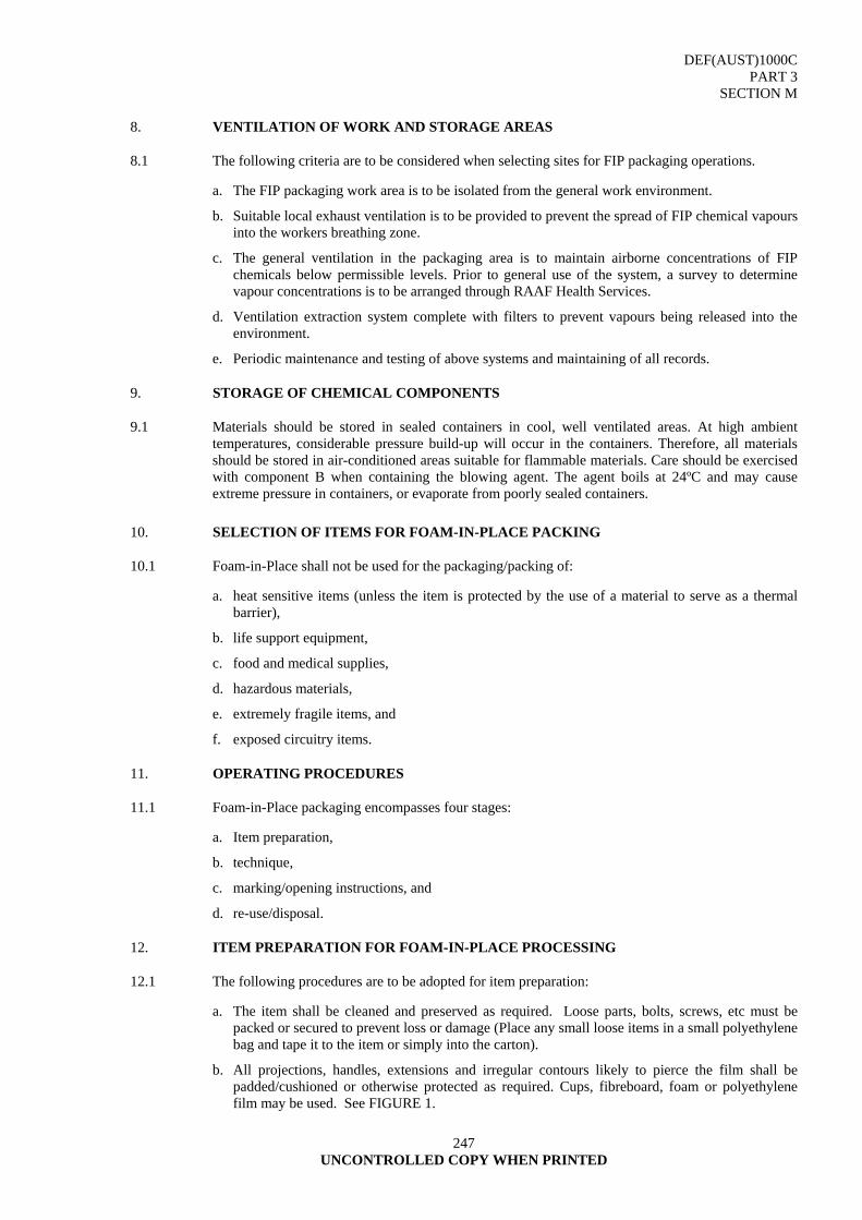
DEF(AUST)1000C PART 3
SECTION M
247 UNCONTROLLED COPY WHEN PRINTED
8. VENTILATION OF WORK AND STORAGE AREAS
8.1 The following criteria are to be considered when selecting sites for FIP packaging operations.
a. The FIP packaging work area is to be isolated from the general work environment.
b. Suitable local exhaust ventilation is to be provided to prevent the spread of FIP chemical vapours into the workers breathing zone.
c. The general ventilation in the packaging area is to maintain airborne concentrations of FIP chemicals below permissible levels. Prior to general use of the system, a survey to determine vapour concentrations is to be arranged through RAAF Health Services.
d. Ventilation extraction system complete with filters to prevent vapours being released into the environment.
e. Periodic maintenance and testing of above systems and maintaining of all records. 9. STORAGE OF CHEMICAL COMPONENTS
9.1 Materials should be stored in sealed containers in cool, well ventilated areas. At high ambient temperatures, considerable pressure build-up will occur in the containers. Therefore, all materials should be stored in air-conditioned areas suitable for flammable materials. Care should be exercised with component B when containing the blowing agent. The agent boils at 24ºC and may cause extreme pressure in containers, or evaporate from poorly sealed containers.
10. SELECTION OF ITEMS FOR FOAM-IN-PLACE PACKING
10.1 Foam-in-Place shall not be used for the packaging/packing of:
a. heat sensitive items (unless the item is protected by the use of a material to serve as a thermal barrier),
b. life support equipment,
c. food and medical supplies,
d. hazardous materials,
e. extremely fragile items, and
f. exposed circuitry items. 11. OPERATING PROCEDURES
11.1 Foam-in-Place packaging encompasses four stages:
a. Item preparation,
b. technique,
c. marking/opening instructions, and
d. re-use/disposal. 12. ITEM PREPARATION FOR FOAM-IN-PLACE PROCESSING
12.1 The following procedures are to be adopted for item preparation:
a. The item shall be cleaned and preserved as required. Loose parts, bolts, screws, etc must be packed or secured to prevent loss or damage (Place any small loose items in a small polyethylene bag and tape it to the item or simply into the carton).
b. All projections, handles, extensions and irregular contours likely to pierce the film shall be padded/cushioned or otherwise protected as required. Cups, fibreboard, foam or polyethylene film may be used. See FIGURE 1.

DEF(AUST)1000C PART 3
SECTION M
248 UNCONTROLLED COPY WHEN PRINTED
CAUTION
FOAM ADHERES TO MOST SURFACES, REMOVAL IS DIFFICULT AND OFTEN
DAMAGING
FIGURE 1
c. Wrap the prepared item in polyethylene film or place in a polyethylene bag and seal with Pressure Sensitive Adhesive Tape (PSAT) to protect the item from the foam (see FIGURE 2).
FIGURE 2
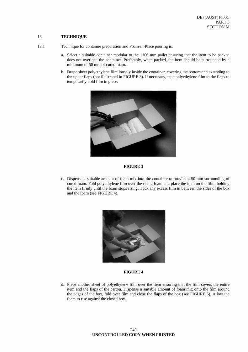
DEF(AUST)1000C PART 3
SECTION M
249 UNCONTROLLED COPY WHEN PRINTED
13. TECHNIQUE
13.1 Technique for container preparation and Foam-in-Place pouring is:
a. Select a suitable container modular to the 1100 mm pallet ensuring that the item to be packed does not overload the container. Preferably, when packed, the item should be surrounded by a minimum of 50 mm of cured foam.
b. Drape sheet polyethylene film loosely inside the container, covering the bottom and extending to the upper flaps (not illustrated in FIGURE 3). If necessary, tape polyethylene film to the flaps to temporarily hold film in place.
FIGURE 3
c. Dispense a suitable amount of foam mix into the container to provide a 50 mm surrounding of cured foam. Fold polyethylene film over the rising foam and place the item on the film, holding the item firmly until the foam stops rising. Tuck any excess film in between the sides of the box and the foam (see FIGURE 4).
FIGURE 4
d. Place another sheet of polyethylene film over the item ensuring that the film covers the entire item and the flaps of the carton. Dispense a suitable amount of foam mix onto the film around the edges of the box, fold over film and close the flaps of the box (see FIGURE 5). Allow the foam to rise against the closed box.
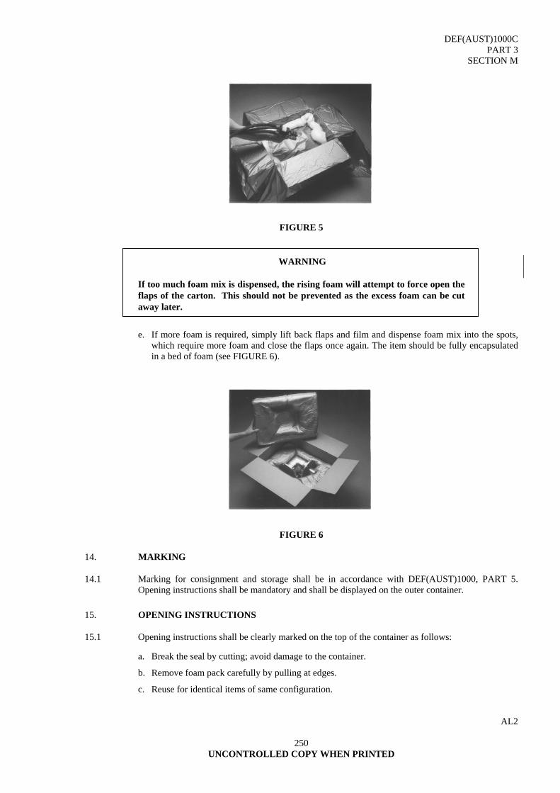
DEF(AUST)1000C PART 3
SECTION M
250 UNCONTROLLED COPY WHEN PRINTED
FIGURE 5
WARNING
If too much foam mix is dispensed, the rising foam will attempt to force open the flaps of the carton. This should not be prevented as the excess foam can be cut away later.
e. If more foam is required, simply lift back flaps and film and dispense foam mix into the spots, which require more foam and close the flaps once again. The item should be fully encapsulated in a bed of foam (see FIGURE 6).
FIGURE 6 14. MARKING
14.1 Marking for consignment and storage shall be in accordance with DEF(AUST)1000, PART 5. Opening instructions shall be mandatory and shall be displayed on the outer container.
15. OPENING INSTRUCTIONS
15.1 Opening instructions shall be clearly marked on the top of the container as follows:
a. Break the seal by cutting; avoid damage to the container.
b. Remove foam pack carefully by pulling at edges.
c. Reuse for identical items of same configuration.
AL2
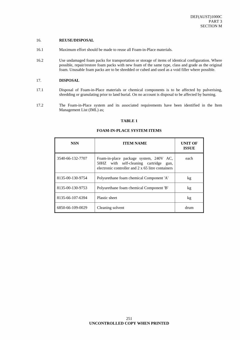
DEF(AUST)1000C PART 3
SECTION M
251 UNCONTROLLED COPY WHEN PRINTED
16. REUSE/DISPOSAL
16.1 Maximum effort should be made to reuse all Foam-in-Place materials.
16.2 Use undamaged foam packs for transportation or storage of items of identical configuration. Where possible, repair/restore foam packs with new foam of the same type, class and grade as the original foam. Unusable foam packs are to be shredded or cubed and used as a void filler where possible.
17. DISPOSAL
17.1 Disposal of Foam-in-Place materials or chemical components is to be affected by pulverising, shredding or granulating prior to land burial. On no account is disposal to be affected by burning.
17.2 The Foam-in-Place system and its associated requirements have been identified in the Item Management List (IML) as;
TABLE 1
FOAM-IN-PLACE SYSTEM ITEMS
NSN ITEM NAME UNIT OF ISSUE
3540-66-132-7707 Foam-in-place package system, 240V AC, 50HZ with self-cleaning cartridge gun, electronic controller and 2 x 65 litre containers
each
8135-00-130-9754 Polyurethane foam chemical Component 'A' kg
8135-00-130-9753 Polyurethane foam chemical Component 'B' kg
8135-66-107-6394 Plastic sheet kg
6850-66-109-0029 Cleaning solvent drum
DOCUMENT IMPROVEMENT PROPOSAL DEF(AUST)1000C - ADF PACKAGING PART 3 : PACKAGING PRACTICE AND MATERIALS The purpose of this form is to solicit comments, which will assist in maintaining the above document as both
practical and realistic. When completed, the form and any additional papers, should be forwarded to: Assistant Program Coordinator
Army Standardisation Land Engineering Agency Defence Plaza Melbourne 3rd Floor 661 Bourke St, MELBOURNE VIC 3000 NB Comments submitted do not constitute or imply authorisation to waive any requirement of the document
or to amend contractual requirements. 1. Has any part of this document created problems or required interpretation in use? State paragraph
no(s) and any rewording suggested. 2. Has any new technology rendered any process obsolete? Suggestions supported by examples are
welcome where the new process/hardware has proved satisfactory. 3. Comments on any requirements considered to be too rigid/too expensive. 4. Remarks (attach any relevant data, which may be of use in improving this document).


REQUESTS FOR DOCUMENTS
Requests for copies of this document, and some Referenced Documents may be directed to the appropriate source listed below:
DEPARTMENT OF DEFENCE (Maritime) Director Naval Platform Systems Department of Defence (Navy Office) Campbell Park Offices (CP4-SP-013) CANBERRA ACT 2600 Attention: NSTDC Telephone: (06) 266 2906 Facsimile: (06) 266 2105 DEPARTMENT OF DEFENCE (Land) Land Engineering Agency Attention: Equipment Information Office Raleigh Road MARIBYRNONG VIC 3032 Postal Address: Private Bag No 12 PO ASCOT VALE VIC 3032 Attention: Equipment Information Manager Telephone: (03) 319 5385 Facsimile: (03) 9319 5382 DEPARTMENT OF DEFENCE (Air) Areospace Technical Standards Document Centre (ATSDC) Common Services System Support Office (CSSSO) Building L7-1 RAAF Williams Laverton VIC 3027 Telephone: (03) 9256 4236 Facsimile: (03) 9256 4888 DEFENCE RESTRICTED NETWORK (DRN) Army Standardisation: http://vbmweb.sor.defence.gov.au/SPECS/Triservice/Directory.htm Aerospace Technical Standards Document Centre http://wilap006.sor.defence.gov.au/Specs/defence.asp ADF Maritime Material Requirements Set: http://defweb.cbr.defence.gov.au/navysyscom/mrs/HomePage.htm (Note: The above websites addresses may change at any time without
notice).
Crown copyright reserved
PUBLISHED UNDER AUTHORITY OF DEPTMENT OF DEFENCE
Copies of DEF(AUST) Documents are obtainable from sources shown inside back cover


![[ A ] SPIRITS ADF [ADF] VODKA - BASIC](https://static.fdocuments.in/doc/165x107/6169d8c211a7b741a34c063e/-a-spirits-adf-adf-vodka-basic.jpg)