![WEEE Directive[1]](https://static.fdocuments.in/doc/165x107/577d35a31a28ab3a6b90ff41/weee-directive1.jpg)
DeeSel.1 Industrial Ethernet Extender Local and Remote ... · 17. En caso de existir, ... waste and...
24
LB532A-L LB532A-R DeeSel.1 Industrial Ethernet Extender Local and Remote Units, G.SHDSL 2-Wire 5.7 Mbps Extend industrial Ethernet connections cost-effectively up to 4.3 miles over existing twisted pair cable.
Transcript of DeeSel.1 Industrial Ethernet Extender Local and Remote ... · 17. En caso de existir, ... waste and...

LB532A-LLB532A-R
DeeSel.1 Industrial Ethernet Extender Local and Remote Units, G.SHDSL 2-Wire 5.7 Mbps
Extend industrial Ethernet connections cost-effectively up to 4.3 miles over existing twisted pair cable.
Black Box Ethernet Extenders
TABLE OF CONTENTS
1. General Information .....................................................................................91.1 Features ..............................................................................................91.2 Description.......................................................................................... 91.3 Power Input Connector ....................................................................... 9
2. Configuration ............................................................................................. 102.1 Hardware (DIP-switch) Configuration ...............................................102.2 DIP Switch Settings .......................................................................... 11
DIP Switch Settings: Data Rate ............................................. 11Ethernet Management Port .................................................... 14
3. Installation.................................................................................................. 163.1 Connecting the Interface ...................................................................163.2 Connecting the Ethernet Interface .................................................... 173.3 Connecting Power ............................................................................ 18
4. Operation ................................................................................................... 194.1 Power-up ..........................................................................................194.2 LED Status Monitors......................................................................... 19
Power (Green) ....................................................................... 20Line Link (Green) ................................................................... 20ETH Link (Green)................................................................... 20
5. Software Upgrade...................................................................................... 20
A. Specifications............................................................................................. 21
A.1 Line Rate ..........................................................................................21
A.2 Ethernet Interface .............................................................................21
A.3 Status LEDs ......................................................................................21Power (Green) ....................................................................... 21Line Link (Green) ................................................................... 21ETH Link (Green)................................................................... 21
A.4 Configuration ....................................................................................21Factory Default Configuration ................................................ 21
A.5 Power and Power Supply Specifications ..........................................22
A.6 Transmission Line .............................................................................22
A.7 Line Coding .......................................................................................22
A.8 Line Interface ....................................................................................22
A.9 Physical Connection .........................................................................22
A.10 Environment ......................................................................................23
724-746-5500 | blackbox.comPage 2
Table of Contents
A.11 Third Party Software Licenses .......................................................... 23
B. Interface Pinouts........................................................................................ 23B.1 Line Port ........................................................................................... 23
B.2 Ethernet Port .................................................................................... 23
724-746-5500 | blackbox.com Page 3

Black Box Ethernet Extenders
RADIO FREQUENCY INTERFERENCE STATEMENTS
FEDERAL COMMUNICATIONS COMMISSION AND INDUSTRY CANADA RADIO FREQUENCY INTERFERENCE STATEMENTS
This equipment generates, uses, and can radiate radio-frequency energy, and if not installed and used properly, that is, in strict accordance with the manufacturer’s instructions, may cause interference to radio communication. It has been tested and found to comply with the limits for a Class A computing device in accordance with the specifications in Subpart B of Part 15 of FCC rules, which are designed to provide rea-sonable protection against such interference when the equipment is operated in a commercial environment. Operation of this equipment in a residential area is likely to cause interference, in which case the user at his own expense will be required to take whatever measures may be necessary to correct the interference.
Changes or modifications not expressly approved by the party responsible for compli-ance could void the user’s authority to operate the equipment.
This digital apparatus does not exceed the Class A limits for radio noise emission from digital apparatus set out in the Radio Interference Regulation of Industry Canada.
Le présent appareil numérique n’émet pas de bruits radioélectriques dépassant les limites applicables aux appareils numériques de la classe A prescrites dans le Règle-ment sur le brouillage radioélectrique publié par Industrie Canada.
724-746-5500 | blackbox.comPage 4
INSTRUCCIONES DE SEGURIDAD
INSTRUCCIONES DE SEGURIDAD
(Normas Oficiales Mexicanas Electrical Safety Statement)
3. Todas las instrucciones de seguridad y operación deberán ser leídas antes de que el aparato eléctrico sea operado.
4. Las instrucciones de seguridad y operación deberán ser guardadas para refer-encia futura.
5. Todas las advertencias en el aparato eléctrico y en sus instrucciones de oper-ación deben ser respetadas.
6. Todas las instrucciones de operación y uso deben ser seguidas.
7. El aparato eléctrico no deberá ser usado cerca del agua—por ejemplo, cerca de la tina de baño, lavabo, sótano mojado o cerca de una alberca, etc..
8. El aparato eléctrico debe ser usado únicamente con carritos o pedestales que sean recomendados por el fabricante.
9. El aparato eléctrico debe ser montado a la pared o al techo sólo como sea recomendado por el fabricante.
10. Servicio—El usuario no debe intentar dar servicio al equipo eléctrico más allá a lo descrito en las instrucciones de operación. Todo otro servicio deberá ser refer-ido a personal de servicio calificado.
11. El aparato eléctrico debe ser situado de tal manera que su posición no interfiera su uso. La colocación del aparato eléctrico sobre una cama, sofá, alfombra o superficie similar puede bloquea la ventilación, no se debe colocar en libreros o gabinetes que impidan el flujo de aire por los orificios de ventilación.
12. El equipo eléctrico deber ser situado fuera del alcance de fuentes de calor como radiadores, registros de calor, estufas u otros aparatos (incluyendo amplificado-res) que producen calor.
13. El aparato eléctrico deberá ser connectado a una fuente de poder sólo del tipo descrito en el instructivo de operación, o como se indique en el aparato.
14. Precaución debe ser tomada de tal manera que la tierra fisica y la polarización del equipo no sea eliminada.
15. Los cables de la fuente de poder deben ser guiados de tal manera que no sean pisados ni pellizcados por objetos colocados sobre o contra ellos, poniendo par-ticular atención a los contactos y receptáculos donde salen del aparato.
724-746-5500 | blackbox.com Page 5

Black Box Ethernet Extenders
16. El equipo eléctrico debe ser limpiado únicamente de acuerdo a las recomenda-ciones del fabricante.
17. En caso de existir, una antena externa deberá ser localizada lejos de las lineas de energia.
18. El cable de corriente deberá ser desconectado del cuando el equipo no sea usado por un largo periodo de tiempo.
19. Cuidado debe ser tomado de tal manera que objectos liquidos no sean derrama-dos sobre la cubierta u orificios de ventilación.
20. Servicio por personal calificado deberá ser provisto cuando:
A. El cable de poder o el contacto ha sido dañado; u
A. Objectos han caído o líquido ha sido derramado dentro del aparato; o
A. El aparato ha sido expuesto a la lluvia; o
A. El aparato parece no operar normalmente o muestra un cambio en su desem-peño; o
A. El aparato ha sido tirado o su cubierta ha sido dañada.
724-746-5500 | blackbox.comPage 6

Safety When Working With Electricity
SAFETY WHEN WORKING WITH ELECTRICITY• This device contains no user serviceable parts. This
device can only be repaired by qualified service personnel.
• Do not open the device when the power cord is con-nected. For systems without a power switch and without an external power adapter, line voltages are present within the device when the power cord is connected.
• For devices with an external power adapter, the power adapter shall be a listed Limited Power Source. The mains outlet that is utilized to power the device shall be within 10 feet (3 meters) of the device, shall be easily accessible, and protected by a circuit breaker in compli-ance with local regulatory requirements.
• For AC powered devices, ensure that the power cable used meets all applicable standards for the country in which it is to be installed.
• For AC powered devices which have 3 conductor power plugs (L1, L2 & GND or Hot, Neutral & Safety/Protective Ground), the wall outlet (or socket) must have an earth ground.
• For DC powered devices, ensure that the interconnecting cables are rated for proper voltage, current, anticipated temperature, flammability, and mechanical serviceability.
• WAN, LAN & PSTN ports (connections) may have hazard-ous voltages present regardless of whether the device is powered ON or OFF. PSTN relates to interfaces such as telephone lines, FXS, FXO, DSL, xDSL, T1, E1, ISDN, Voice, etc. These are known as “hazardous network volt-ages” and to avoid electric shock use caution when working near these ports. When disconnecting cables for these ports, detach the far end connection first.
• Do not work on the device or connect or disconnect cables during periods of lightning activity.
WARNING
724-746-5500 | blackbox.com Page 7
Black Box Ethernet Extenders
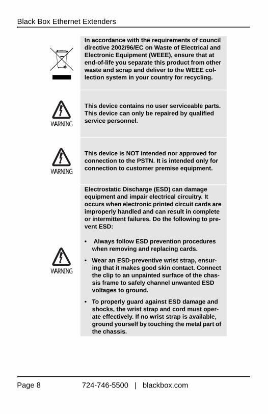
In accordance with the requirements of council directive 2002/96/EC on Waste of Electrical and Electronic Equipment (WEEE), ensure that at end-of-life you separate this product from other waste and scrap and deliver to the WEEE col-lection system in your country for recycling.
This device contains no user serviceable parts. This device can only be repaired by qualified service personnel.
This device is NOT intended nor approved for connection to the PSTN. It is intended only for connection to customer premise equipment.
Electrostatic Discharge (ESD) can damage equipment and impair electrical circuitry. It occurs when electronic printed circuit cards are improperly handled and can result in complete or intermittent failures. Do the following to pre-vent ESD:
• Always follow ESD prevention procedures when removing and replacing cards.
• Wear an ESD-preventive wrist strap, ensur-ing that it makes good skin contact. Connect the clip to an unpainted surface of the chas-sis frame to safely channel unwanted ESD voltages to ground.
• To properly guard against ESD damage and shocks, the wrist strap and cord must oper-ate effectively. If no wrist strap is available, ground yourself by touching the metal part of the chassis.
WARNING
WARNING
WARNING
724-746-5500 | blackbox.comPage 8

1. GENERAL INFORMATION
Thank you for your purchase of this Black Box product. This product has been thor-oughly inspected and tested and is warranted for one year for parts and labor. If any questions or problems arise during installation or use of this product, contact Black Box Technical Support at 724-746-5500 or info@Black Box.com.
1.1 FEATURES
• High speed extension with speeds up to 5.696 Mbps
• Two 2-wire line connections via built-in RJ-45 ports (C1 and C2)
• 10- or 100Base-T and full or half-duplex Ethernet port for direct connection of four Ethernet devices
• Extends Ethernet up to 3.4 miles (5.48 km) using 24 AWG/0.5mm wire (192 kbps speed) per hop
• DIN Rail mount
• -40 to 85ºC operating temperature
1.2 DESCRIPTION
The Black Box LB532A-L and LB532A-R Industrial Ethernet Extenders are easy to use and take advantage of existing copper twisted-pair infrastructure to connect Ethernet networks or devices at high speeds over long distances. The LB532A-L and LB532A-R deliver speeds up to 5.696 Mbps with distances ranging from 3.5 to 5.48 km (2.2 to 3.4 miles) on standard 0.5 mm (24 AWG) voice-grade twisted pair. Whether setting up a private network backbone to a corporate LANs or remote office or connecting network enabled devices such as PCs, digital sensors or IP cameras—Black Box Ethernet Extenders offer the best combination of speed and distance in the industry. The LB532A-L and LB532A-R temperature specs allow for operation at -40 to 85ºC.
1.3 POWER INPUT CONNECTOR
The LB532A-L and LB532A-R come with an external AC universal power supply. (For additional specifications and details on power and power supply, see Appendix A.5 on page 22.)
• The power connection to the LB532A-L and LB532A-R is a terminal block
• Rated voltage: 5 VDC
724-746-5500 | blackbox.com Page 9

Black Box Ethernet Extenders
• Rated current: 1 A DC
Figure 1. Terminal block power connection
• Output from power supply: 5 VDC, 2A regulated (± 5%)
• Input to power supply: universal input 100–240 VAC 50/60 Hz 0.3A
2. CONFIGURATION
You can configure the LB532A-L and LB532A-R only through the hardware configura-tion via DIP switches.
2.1 HARDWARE (DIP-SWITCH) CONFIGURATION
The only configurable parameter is the data rate, set by DIP switches S4-2 through S4-8 (see Table 2 on page 11). All other DIP switches should remain in the OFF posi-tion. When configuring the data rate, set the DIP switches to the desired rate before applying power to the LB532A-L or the LB532A-R.
NOTE: Factory Default Configuration: 5.696 Mbps (DIP are all OFF)
The external AC adapter shall be a listed limited power source that incorporates a disconnect device and shall be positioned within easy reach of the operator. Ensure that the AC power cable meets all applicable standards for the country in which it is to be installed, and that it is connected to a wall outlet that has earth ground.
Table 1: LB532A-M configurable parameters
Parameter DescriptionPossible Values
Data Rate/ Timeslots
Defines the number of timeslots. The data rate is calculated by the equation:
data rate = timeslots x 64k.
1-72 timeslots
Power+ -
CAUTION
724-746-5500 | blackbox.comPage 10
Configuration
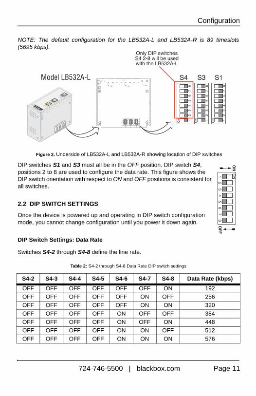
NOTE: The default configuration for the LB532A-L and LB532A-R is 89 timeslots (5695 kbps).
Figure 2. Underside of LB532A-L and LB532A-R showing location of DIP switches
DIP switches S1 and S3 must all be in the OFF position. DIP switch S4, positions 2 to 8 are used to configure the data rate. This figure shows the DIP switch orientation with respect to ON and OFF positions is consistent for all switches.
2.2 DIP SWITCH SETTINGS
Once the device is powered up and operating in DIP switch configuration mode, you cannot change configuration until you power it down again.
DIP Switch Settings: Data Rate
Switches S4-2 through S4-8 define the line rate.
Table 2: S4-2 through S4-8 Data Rate DIP switch settings
S4-2 S4-3 S4-4 S4-5 S4-6 S4-7 S4-8 Data Rate (kbps)
OFF OFF OFF OFF OFF OFF ON 192OFF OFF OFF OFF OFF ON OFF 256OFF OFF OFF OFF OFF ON ON 320
OFF OFF OFF OFF ON OFF OFF 384OFF OFF OFF OFF ON OFF ON 448OFF OFF OFF OFF ON ON OFF 512
OFF OFF OFF OFF ON ON ON 576
OF
F
ON
12
34
56
78
ON
724-746-5500 | blackbox.com Page 11
Black Box Ethernet Extenders
OFF OFF OFF ON OFF OFF OFF 640OFF OFF OFF ON OFF OFF ON 704OFF OFF OFF ON OFF ON OFF 768
OFF OFF OFF ON OFF ON ON 832OFF OFF OFF ON ON OFF OFF 896OFF OFF OFF ON ON OFF ON 960
OFF OFF OFF ON ON ON OFF 1024OFF OFF OFF ON ON ON ON 1088OFF OFF ON OFF OFF OFF OFF 1152
OFF OFF ON OFF OFF OFF ON 1216OFF OFF ON OFF OFF ON OFF 1280OFF OFF ON OFF OFF ON ON 1344
OFF OFF ON OFF ON OFF OFF 1408OFF OFF ON OFF ON OFF ON 1472OFF OFF ON OFF ON ON OFF 1536
OFF OFF ON OFF ON ON ON 1600OFF OFF ON ON OFF OFF OFF 1664OFF OFF ON ON OFF OFF ON 1728
OFF OFF ON ON OFF ON OFF 1792OFF OFF ON ON OFF ON ON 1856OFF OFF ON ON ON OFF OFF 1920
OFF OFF ON ON ON OFF ON 1984OFF OFF ON ON ON ON OFF 2048OFF OFF ON ON ON ON ON 2112
OFF ON OFF OFF OFF OFF OFF 2176OFF ON OFF OFF OFF OFF ON 2240OFF ON OFF OFF OFF ON OFF 2304
OFF ON OFF OFF OFF ON ON 2368OFF ON OFF OFF ON OFF OFF 2432OFF ON OFF OFF ON OFF ON 2496
OFF ON OFF OFF ON ON OFF 2560OFF ON OFF OFF ON ON ON 2624OFF ON OFF ON OFF OFF OFF 2688
OFF ON OFF ON OFF OFF ON 2752OFF ON OFF ON OFF ON OFF 2816
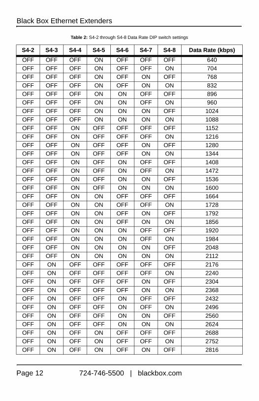
Table 2: S4-2 through S4-8 Data Rate DIP switch settings
S4-2 S4-3 S4-4 S4-5 S4-6 S4-7 S4-8 Data Rate (kbps)
724-746-5500 | blackbox.comPage 12

Configuration
OFF ON OFF ON OFF ON ON 2880
OFF ON OFF ON ON OFF OFF 2944OFF ON OFF ON ON OFF ON 3008OFF ON OFF ON ON ON OFF 3072
OFF ON OFF ON ON ON ON 3136OFF ON ON OFF OFF OFF OFF 3200OFF ON ON OFF OFF OFF ON 3264
OFF ON ON OFF OFF ON OFF 3328OFF ON ON OFF OFF ON ON 3392OFF ON ON OFF ON OFF OFF 3456
OFF ON ON OFF ON OFF ON 3520OFF ON ON OFF ON ON OFF 3584OFF ON ON OFF ON ON ON 3648
OFF ON ON ON OFF OFF OFF 3712OFF ON ON ON OFF OFF ON 3776OFF ON ON ON OFF ON OFF 3840
OFF ON ON ON OFF ON ON 3904OFF ON ON ON ON OFF OFF 3968OFF ON ON ON ON OFF ON 4032
OFF ON ON ON ON ON OFF 4096OFF ON ON ON ON ON ON 4160ON OFF OFF OFF OFF OFF OFF 4224
ON OFF OFF OFF OFF OFF ON 4288ON OFF OFF OFF OFF ON OFF 4352ON OFF OFF OFF OFF ON ON 4416
ON OFF OFF OFF ON OFF OFF 4480ON OFF OFF OFF ON OFF ON 4544ON OFF OFF OFF ON ON OFF 4608
ON OFF OFF OFF ON ON ON 4672ON OFF OFF ON OFF OFF OFF 4736ON OFF OFF ON OFF OFF ON 4800
ON OFF OFF ON OFF ON OFF 4864ON OFF OFF ON OFF ON ON 4928ON OFF OFF ON ON OFF OFF 4992
Table 2: S4-2 through S4-8 Data Rate DIP switch settings
S4-2 S4-3 S4-4 S4-5 S4-6 S4-7 S4-8 Data Rate (kbps)
724-746-5500 | blackbox.com Page 13

Black Box Ethernet Extenders
Ethernet Management Port
The LB532A-L and LB532A-R each offer a 10/100 Ethernet port to view the current DIP switch settings via Telnet sessions. The Ethernet interface default IP address for the LB532A-L and the LB532A-M is 192.168.200.1 and the default IP address for the LB532A-R is 192.168.200.2. Log into the LB532A-M management port using the pass-word superuser.
Through the Ethernet management port, the following variables can be configured or monitored:
• status: Shows the general configuration and status of the unit
• info: Shows system information
• upgrade: Enables the system upgrade prompt
Line Status Command. The status command shows the following line status informa-tion: sync state, link state, link speed, error counters, line condition, noise margin, and test mode status.
The following status information is available through the Command Line Interface:
• sync state: Out of Sync, Acquiring Sync, In Sync, or Losing Sync
• link state: In Progress, Success, Deactivated, or Idle
ON OFF OFF ON ON OFF ON 5056ON OFF OFF ON ON ON OFF 5120ON OFF OFF ON ON ON ON 5184
ON OFF ON OFF OFF OFF OFF 5248ON OFF ON OFF OFF OFF ON 5312ON OFF ON OFF OFF ON OFF 5376
ON OFF ON OFF OFF ON ON 5440ON OFF ON OFF ON OFF OFF 5504ON OFF ON OFF ON OFF ON 5568
ON OFF ON OFF ON ON OFF 5632ON OFF ON OFF ON ON ON 5696
Table 2: S4-2 through S4-8 Data Rate DIP switch settings
S4-2 S4-3 S4-4 S4-5 S4-6 S4-7 S4-8 Data Rate (kbps)
724-746-5500 | blackbox.comPage 14

Configuration
NOTE: Link State vs. Sync State—The Link State describes whether the line is train-ing (in progress), linked (success), deactivated (we don’t have an option to deactivate the modem, so the user should not see this), or idle.
NOTE: The Sync State describes whether no sync words have been found (out of sync), there are no sync word errors (in sync), or whether we are transitioning from out of sync to in sync (acquiring sync) or vice versa (losing sync). Typically, when the link is training, the sync state goes from out of sync to acquiring sync to in sync.
• actual rate: The actual rate at which the link is running (minus overhead).
• noise margin: The maximum tolerable increase in external noise power that still allows for BER of less than 1x 10⁻⁷.
• error counters: The following error counters are available: CRC and LOSW (Loss of Sync Word)
Help Commands. The following commands are provided to help the user find the cor-rect command:
• help: Lists all the commands that the console recognizes
Example Command Line Interface Session.
LB532A Command ShellPassword: LB532A> statusconfiguration:link mode: remotelink rate: 5696line probe: disabledstatus:actual rate: 0loss of signal: unavailablenoise margin: 0snr: 0sync state: out of synclink state: idlepower scale: 0dBerror counters:crc: 0losw: 0
LB532A> exit
NOTE: The line probe feature is a future product enhancement.
724-746-5500 | blackbox.com Page 15
Black Box Ethernet Extenders
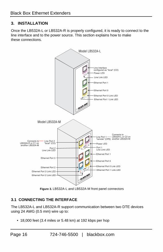
3. INSTALLATION
Once the LB532A-L or LB532A-R is properly configured, it is ready to connect to the line interface and to the power source. This section explains how to make these connections.
Figure 3. LB532A-L and LB532A-M front panel connectors
3.1 CONNECTING THE INTERFACE
The LB532A-L and LB532A-R support communication between two DTE devices using 24 AWG (0.5 mm) wire up to:
• 18,000 feet (3.4 miles or 5.48 km) at 192 kbps per hop
724-746-5500 | blackbox.comPage 16

• 11,000 feet (2.2 miles or 3.5 km) at 5696 kbps per hop
Two things are essential:
1. The LB532A-L model works with the LB532A-R model. Every local line port must connect to a remote line port.
Figure 4. Local to remote connection
2. To function properly, the LB532A needs one twisted pair of metallic wire. This twisted pair must be unconditioned, dry, metallic wire, between 19 (0.9mm) and 26 AWG (0.4mm) (the higher number gauges will limit distance). Standard dial-up telephone circuits, or leased circuits that run through signal equalization equipment, or standard, flat modular telephone type cable, are not acceptable.
The RJ-45 line connector on the LB532A’s twisted pair interface is polarity insensitive and is wired for a two-wire interface.
3.2 CONNECTING THE ETHERNET INTERFACE
This section describes how to connect the Ethernet ports to your network equipment.
The RJ-45 ports labeled Ethernet are the Auto-MDIX 10/100Base-T interface. These ports are designed to connect directly to a 10/100Base-T device or network. You may connect these ports to a hub or PC using a straight through or crossover cable that is up to 328 ft long.
The interconnecting cables shall be acceptable for external use and shall be rated for the proper application with respect to voltage, cur-rent, anticipated temperature, flammability, and mechanical serviceability.
CAUTION
724-746-5500 | blackbox.com Page 17
Black Box Ethernet Extenders
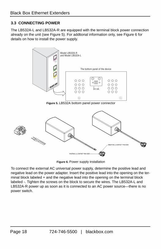
3.3 CONNECTING POWER
The LB532A-L and LB532A-R are equipped with the terminal block power connection already on the unit (see Figure 5). For addtional information only, see Figure 6 for details on how to install the power supply.
Figure 5. LB532A bottom panel power connector
Figure 6. Power supply installation
To connect the external AC universal power supply, determine the positive lead and negative lead on the power adapter. Insert the positive lead into the opening on the ter-minal block labeled + and the negative lead into the opening on the terminal block labeled -. Tighten the screws on the block to secure the wires. The LB532A-L and LB532A-R power up as soon as it is connected to an AC power source—there is no power switch.
724-746-5500 | blackbox.comPage 18

4. OPERATION
Once the LB532A-L or LB532A-R is properly configured and installed, it should oper-ate transparently. The following sections describe power-up, reading the LED status monitors, and using the built-in loopback test modes.
4.1 POWER-UP
To apply power to the LB532A-L or LB532A-R, first be sure that you have read section 1.3, “Power Input Connector” on page 9, and that the unit is connected to the appropri-ate power source. Power up the unit.
4.2 LED STATUS MONITORS
There are four LEDs that provide feedback on the state of the unit. Figure 7 on page 19 shows the location of the front panel LEDs.
Figure 7. LB532A-L or LB532A-R and LB532A-M front panel LEDs
The external AC adaptor shall be a listed limited power source that incorporates a disconnect device and shall be positioned within easy reach of the operator. Ensure that the AC power cable meets all applicable standards for the country in which it is to be installed, and that it is connected to a wall outlet that has earth ground.
CAUTION
724-746-5500 | blackbox.com Page 19

Black Box Ethernet Extenders
Power (Green)
The Power LED glows solid during normal operation. At startup, during the POST, the LED blinks once every second. If the POST fails, the unit does not enter normal opera-tion, and the LED blinks once every 0.4 seconds.
Line Link (Green)
The Line LED glows solid while a link is established. While the link is training, it blinks once every second.
ETH Link (Green)
The Ethernet Link LEDs show that there is an active physical connection to the con-sole, or an active physical connection to an Ethernet device.
5. SOFTWARE UPGRADE
The software upgrade feature is available through TFTP. The software upgrade takes approximately 1 to 2 minutes to complete. To upgrade the software:
1. Telnet to LB532A-L via the Eth 0 or Eth 1 port through the default IP address 192.168.200.1/24 or Telnet to LB532A-R via the Eth 0 or Eth 1 port through the default Ip address 192.168.200.2/24.
2. Enter the upgrade <TFTP server IP address>:/<filename> command to begin the upgrade.
After approximately 1 to 2 minutes, the LB532A-L or LB532A-R will operate with the upgraded software.
724-746-5500 | blackbox.comPage 20

A. SPECIFICATIONS
A.1 LINE RATE
192 to 5696 kbps (64k increments; 3-89 timeslots)
A.2 ETHERNET INTERFACE
Two RJ-45, 10/100Base-T, IEEE 802.3 Ethernet
A.3 STATUS LEDS
Power (Green)
The Power LED glows solid during normal operation. At startup, during the POST, the LED blinks once every second. If the POST fails, the unit does not enter normal opera-tion, and the LED blinks once every 0.4 seconds.
Line Link (Green)
The Line LED glows solid while a link is established. While the link is training, it blinks once every second.
ETH Link (Green)
The Ethernet Link LEDs show that there is an active physical network connection to the Console or an Ethernet device.
A.4 CONFIGURATION
Configuration is done only with externally accessible DIP switches.
Factory Default Configuration
• All DIP switches are OFF
• 5.696 Mbps (89 timeslots)
• Look at the label to determine if the unit is “remote” or “local,” or via Telnet ses-sion
• LB532A-M from “remote” and “local” ports
724-746-5500 | blackbox.com Page 21

Black Box Ethernet Extenders
A.5 POWER AND POWER SUPPLY SPECIFICATIONS
The LB532A-L and LB532A-R comes with an external AC universal power supply.
• The power connection to the LB532A-L and LB532A-R is a terminal block (see Figure 8)
• There is one fuse in the equipment rated at 250V, 500 mA, 2 sec.
• Rated voltage: 5 VDC
• Rated current: 1 A DC
Figure 8. Terminal block power connection
• Output from power supply: 5 VDC, 2A, regulated
• Input to power supply: universal input 100–240 VAC 50/60 Hz 0.3A
A.6 TRANSMISSION LINE
Single Twisted Pair
A.7 LINE CODING
TC-PAM (Trellis Coded Pulse Amplitude Modulation)
A.8 LINE INTERFACE
Transformer coupled, 2500 Vrms isolation
A.9 PHYSICAL CONNECTION
RJ-45, 2-wire polarity insensitive pins 4 and 5
The external AC adapter shall be a listed limited power source that incorporates a disconnect device and shall be positioned within easy reach of the operator. Ensure that the AC power cable meets all applicable standards for the country in which it is to be installed, and that it is connected to a wall outlet that has earth ground.
Power+ -
CAUTION
724-746-5500 | blackbox.comPage 22
Interface Pinouts
A.10 ENVIRONMENT
Operating temp: -40 to 185°F (-40 to 85°C)
Relative Humidity: 8 to 90% non-condensing
Altitude: 0 to 15,000 feet (0 to 4,600 meters)
A.11 THIRD PARTY SOFTWARE LICENSES
NOTE: The LB532A-L and LB532A-R includes software developed under third party licenses.
B. INTERFACE PINOUTS
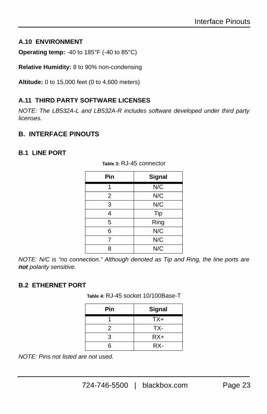
B.1 LINE PORT
NOTE: N/C is “no connection.” Although denoted as Tip and Ring, the line ports are not polarity sensitive.
B.2 ETHERNET PORT
NOTE: Pins not listed are not used.
Table 3: RJ-45 connector
Pin Signal
1 N/C
2 N/C3 N/C4 Tip
5 Ring6 N/C7 N/C
8 N/C
Table 4: RJ-45 socket 10/100Base-T
Pin Signal
1 TX+
2 TX-3 RX+6 RX-
724-746-5500 | blackbox.com Page 23

LB532A-L version 1