Deep Well Disposal of Liquid Mine Wastes
27
39 DEEP WELL DISPOSAL OF LIQUID MINE WASTES by Erie C. Donaldson Research Chemist, Bartlesville Petroleum Research Center, Bureau of Mines, U.S. Department of the Interior, Bartlesville, Oklahoma ABSTRACT The Bureau of Mines has investigated the applicability of subsur- face disposal of liquid wastes and has studied two disposal systems that may be of particular interest to the mining industry. One system is discharging a sulfuric acid waste solution arising from a leaching process for the extraction of uranium from ore, while the other disposes of a highly corrosive waste containing hydrochloric acid, chlorinated hydrocarbons, chlorine, bromine, and sulfuric acid. In both cases, the hydrostatic head of the column of fluid in the well is sufficient to inject the waste. Operation has been interrupted only by maintenance problems arisino from corrosion. Continuous monitoring of the fresh water aquifers above the disposal formations has shown that after more than 8 years of operation no waste, or disposal formation water, has entered the fresh water zones. INTRODUCTION Subsurface disposal of concentrated chemical solutions is not a new process. The petroleum producing industry has been using the method since about 1920 for disposal of oilfield brine. Beginning about 1950, a few companies of the chemical processing industry very cautiously applied the method to a few, difficult, liquid-waste-dis- posal problems, and by 1962 about 30 industrial subsurface disposal systems were in9ooeration. Since then, the number has increased to almost 200 (3).-;‘ The experience of the petroleum and chemical industries has shown that subsurface disposal is applicable to any liquid waste. Concentrated acid wastes, caustics, neutral solutions of salts, highly toxic organic phosphates, acrolein and chlorides, and concen- trated solutions of other organic compounds are now being injected into deep geologic formations. This method offers a solution to the 2/ Underlined numbers in parentheses refer to items in the list of references at the end of this paper.
Transcript of Deep Well Disposal of Liquid Mine Wastes

39
DEEP WELL DISPOSAL OF LIQUID MINE WASTES
by
Erie C. DonaldsonResearch Chemist, Bartlesville Petroleum Research Center,
Bureau of Mines, U.S. Department of the Interior, Bartlesville, Oklahoma
ABSTRACT
The Bureau of Mines has investigated the applicability of subsurface disposal of liquid wastes and has studied two disposal systems that may be of particular interest to the mining industry. One system is discharging a sulfuric acid waste solution arising from a leaching process for the extraction of uranium from ore, while the other disposes of a highly corrosive waste containing hydrochloric acid, chlorinated hydrocarbons, chlorine, bromine, and sulfuric acid. In both cases, the hydrostatic head of the column of fluid in the well is sufficient to inject the waste. Operation has been interrupted only by maintenance problems arisino from corrosion. Continuous monitoring of the fresh water aquifers above the disposal formations has shown that after more than 8 years of operation no waste, or disposal formation water, has entered the fresh water zones.
INTRODUCTION
Subsurface disposal of concentrated chemical solutions is not a new process. The petroleum producing industry has been using the method since about 1920 for disposal of oilfield brine. Beginning about 1950, a few companies of the chemical processing industry very cautiously applied the method to a few, difficult, liquid-waste-disposal problems, and by 1962 about 30 industrial subsurface disposal systems were in9ooeration. Since then, the number has increased to almost 200 (3).-;‘
The experience of the petroleum and chemical industries has shown that subsurface disposal is applicable to any liquid waste. Concentrated acid wastes, caustics, neutral solutions of salts, highly toxic organic phosphates, acrolein and chlorides, and concentrated solutions of other organic compounds are now being injected into deep geologic formations. This method offers a solution to the
2/ Underlined numbers in parentheses refer to items in the list of references at the end of this paper.
40
disposal of large volumes of waste obtained from leaching operations or other concentrated liquid solutions that are kept in lined ponds to be decreased in volume by evaporation. It also offers an alternative solution to disposing of large volumes of liquid waste that must be processed at great expense before they can be discharged into surface streams. Increasing demands by the general populace for closer. Government supervision and regulation of industrial waste discharge into surface waters is making subsurface waste disposal more attractive.
Each subsurface disposal system is unique because it must be designed to process a specific waste mixture for injection into a particular geologic formation having individual characteristics that dictate the design of the well. However, general principles of design and construction are applicable to all subsurface injection systems.' Therefore, this paper is presented in two parts: First, the general technology of subsurface disposal systems is presented with a few notations on cost, and second, very detailed discussions are presented of two disposal systems that are of particualr interest to the mining industry.
SURFACE EQUIPMENT
Surface equipment required for a subsurface disposal system depends on the volume of the waste and the type of treatment that is necessary prior to delivery to the waste-disposal well. Regardless of the simplicity of the system, a storage tank or gravity drainage sump is used for collection of the waste near the site of the disposal well. If the waste is free of suspended solids and is noncorrosive, the collecting tank, transfer pipes, injection pump, and controls may be the only required surface equipment. There are a few such installations, but generally additional equipment is necessary.
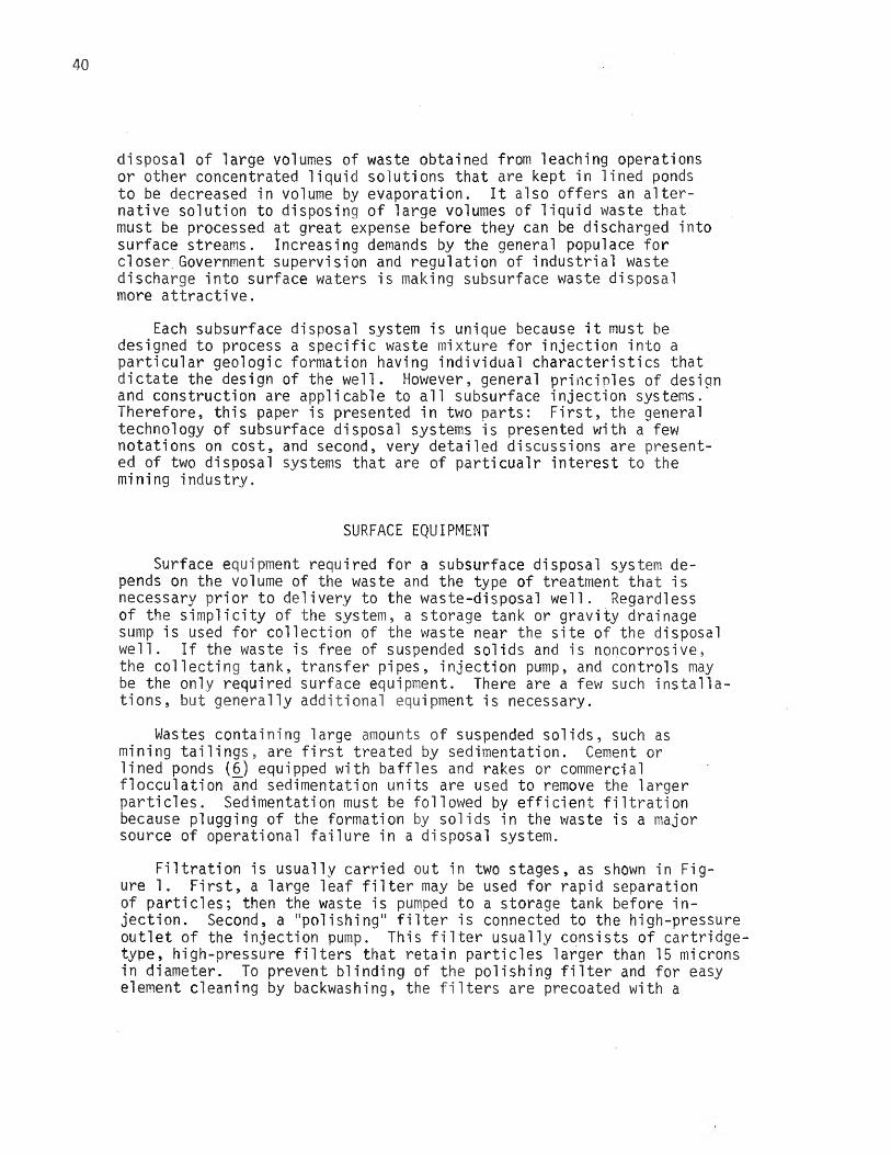
Wastes containing large amounts of suspended solids, such as mining tailings, are first treated by sedimentation. Cement or lined ponds (6J equipped with baffles and rakes or commercial flocculation and sedimentation units are used to remove the larger particles. Sedimentation must be followed by efficient filtration because plugging of the formation by solids in the waste is a major source of operational failure in a disposal system.
Filtration is usually carried out in two stages, as shown in Figure 1. First, a large leaf filter may be used for rapid separation of particles; then the waste is pumped to a storage tank before injection. Second, a "polishing" filter is connected to the high-pressure outlet of the injection pump. This filter usually consists of cartridge- type, high-pressure filters that retain particles larger than 15 microns in diameter. To prevent blinding of the polishing filter and for easy element cleaning by backwashing, the filters are precoated with a

Sedimentation
Chemical treater ( corrosion )
Chemical treater (pH contro l)
Polishingf i l t e r
Disposal we 11
FIGURE I -Surface Equipment used in Subsurface Water Disposal Systems .

42
filter aid such as diatomaceous earth.
A chemical treater controls corrosion of surface equipment and helps to prevent plugging of the underground-disposal formation by insoluble corrosion products. This treater is equipped with volumetric controls for adding a commercial inhibitor to the waste solution as it enters the collecting tank. Occasionally a liquid waste product outside of a specific pH range will form precipitates, and then a chemical treater is used for constant pH monitoring and adjustment.The pH controls are equipped with an automatic shutdown and alarm system for wastes having pH's outside of the safe operating range.
The waste is contained in a clear-waste tank before injection.This tank is equipped with a 1iquid-level-sensing device that will turn off the injection pump when the fluid in the tank reaches a minimi m level.
The size and type of injection pump is governed by the wellhead pressure, the volume of fluid, and the necessary rate of injection at peak loads. A few installations require no injection pump because the hydrostatic pressure of the column of waste in the disposal well exerts sufficient pressure at the subsurface face of the formation to inject the waste. If the well head pressure for waste injection is less than 150 psi, simple single-stage centrifugal pumps can be used, but at higher pressures multiplex piston-type or multistage centrifugal pumps are needed. Hence, selection of an injection pump must be delayed until the disposal well is ready for operation and pumping tests can be made.
Some requirements for surface equipment and pretreatment of waste can be determined by testing of the waste and the water of the disposal formation. Such tests can indicate compatibility of the formation water and waste and dictate the treatment required. But, even though it is possible to run laboratory tests of compatibility, it is very difficult to duplicate conditions as they exist in the subsurface. A laboratory mixture of the two fluids that apparently is satisfactory may be incompatible in the subsurface, The opposite may also be true. Bernard (1_) made some studies by pumping water solutions into sandstone samples that contained incompatible interstitial solutions. He did not observe a decrese in permeability that would have indicated plugging. No solution has been provided for the problem of incompatibility of wastes with formation water. Chemical analysis can reveal the areas of possible difficulties that can be corrected by chemical or physical treatment of the waste. If treatment is too costly or a mixture of the waste and formation water produces copious precipitates, a large volume of fresh water can be injected ahead of the waste to act as a buffer between the waste and the interstitial water.

43
DISPOSAL WELL DESIGN
A waste disposal well must be designed for complete protection of the fresh water aquifers through which the well is drilled. Generally, a 15-inch=diameter hole is drilled to a depth of 200 feet below the deepest fresh water aquifer encountered. Surface casing, shown in Figure 2, with an outside diameter of about 10 inches is then run to the bottom of the hole, leaving a 2 1/2-inch annulus between the casing and the wall of the drill-hole which is filled with cement. This procedure effectively seals off the fresh water aquifers.
After cement around the surface casing has set, drilling is continued with a 9-inch=diameter bit to the top of a potential disposal formation. Cores of the disposal zone are cut for laboratory examination, and the hole is logged. A caliper log graphically portrays the diameter of the hole throughout its entire depth. An electric log indicating the location of aquifers is made by tracing the resistance to an electric current as the tool is raised in the well. When a suitable disposal formation is selected, a 7-inch 0D casing, called the injection casing, is installed, and cement is circulated to the surface in the annulus between the casing and the wellbore, as shown in Figure 2.
The well is completed in the disposal zone in one of many methods that depends upon the nature of the formation, the waste intended for disposal, and accepted drilling practices within the area. Three of the most frequently used completion methods are illustrated in Figure 3.
If the formation is friable, indicating that the wellbore may have a tendency to cave and fill the bottom of the hole, cased-hole completion (Figure 3A) would provide positive support for the wellbore walls. For this type of completion, the hole is drilled to the bottom of the disposal formation, casing is set, and cement is circulated to the surface. The most permeable zones of the formation are then perforated by shot- or jet-type tool.
If the disposal zone is a hard consolidated sandstone or a vugular carbonate formation, an open-hole completion (Figure 3B) may be used. Casing is set at the top of the disposal formation and cemented to the surface. Then an open hole is drilled to the bottom of the disposal zone. Open-hole completion is also used when very corrosive wastes are to be injected, because products from corrosion of the casing at the disposal zone may plug the formation. Corrosion will also result in crumbling of the cemented portion of the casing adjacent to the disposal zone filling the hole with debris, thus diminishing the efficiency of waste injection.
The third general type of completion, gravel pack (Figure 3C), is used in unconsolidated sands to prevent sand from filling the bottom section of the injection casing or tubing which would restrict the flow of the waste solution. One way of gravel packing is to pump graded sizes of sand in a brine carrier into the formation. The sands and

FIGURE 2 . - W aste-D isposal Well

45
9 - in ch diam hole7 - i n c h - 0 D casing 3-L inch-0 D tubingPackerCement
Gravel
Disposal fo rma t ion
F I G U R E 3.-D isp o sa l-W e ll Completion Methods.

46
gravel pack together at the bottom of the casing to form a tortuous path for sand moving toward the well casing. The formation sand jams and movement stops, similar to the action of fine particles on a precoat filter. Space for unrestricted liquid flow is left between the grains of sand and gravel.
In a few cases, the waste has been injected through the injection casing, but this practice is not advisable even with plastic-coated pipe. Assurance against pinholes in the plastic coating cannot be guaranteed, and corrosion could destroy the most expensive portion of the disposal system, the injection casing, markedly decreasing the life of the installation. Protection of the injection casing is best afforded by using an injection tubing string inside of the casing. The tubing strings are sometimes made of corrosive resistant metal alloys, but the most popular material is a fiberglass-epoxy tubing because of its high resistance to corrosive materials and its light weight. Usually a packer is installed at the bottom of the long string of tubing in the annulus between the casing and tubing (Figure 3). Additional protection of the injection casing is afforded by filling the annulus with oil and monitoring the pressure for immediate indication of leak in the injection tubing.
WELL STIMULATION
During well completion, the face of the formation is cleaned of drilling mud, and pumping tests are conducted to determine the flow rate and pressure characteristics of the well. If high wellhead pressures (greater than 500 psi) are required for injection of the waste, acid treatment of the formation or hydraulic fracturing may be considered for decreasing the pressure requirements.
Acidizing is accomplished by injecting hydrochloric acid containing a corrosion inhibitor. Carbonate salts and other minerals are dissolved by the acid increasing the effective permeability of the formation near the wellbore.
Hydraulic fracturing, induced by pumping liquid in at high pressure until the strata are ruptured, produces cracks in the formation extending outward from the well. When the fractures are formed, propping agents such as sand or glass beads are pumped into the cracks to keep them open. Fracturing increases the effective area of the wellbore in the disposal formation, thus reducing the pressure required for injection.
Acidizing and fracturing are also used to stimulate injection into old disposal wells that have become plugged by corrosion products or by suspended solids in the waste.

47
CHARACTERISTICS OF SUBSURFACE FORMATIONS
A subsurface disposal system can be successful only if a porous, permeable formation of wide areal extent is available at sufficient depth to insure safety in storage and retention of the injected fluids.An impermeable zone, such as shale or evaporite, must overlie the injection horizon to prevent vertical migration of the wastes or displaced formation brines into fresh water aquifers or even to the surface (Figure 4). It is also desirable to have an impermeable zone underlie the disposal formation.
If the density of the waste is significantly less than that of the formation brine, an anticlinal structure (Figure 4A) would be better suited for storage of the waste. The reverse is true if the density of the waste is greater than that of the brine (Figure 4B).
Natural formation waters are displaced by the injected fluids. Therefore, if no provision is made for withdrawal of brines from a confined disposal formation, the life of the disposal system will depend on the amount of space that can be made available for waste storage by compression of the interstitial fluids (gas and brine) and the rock matrix. The reservoir pressure would gradually build to a point where continued injection would be inadvisable because of possibly fracturing the confining strata. However, of the disposal installations that were studied in detail (2J, no limitations of fluid injection were experienced due to excessive pressure caused by fluid confinement. Many of these systems have been in constant use for 15 years, with only mechanical failures that v/ere easily corrected.
The porosity and bulk volume of a confined formation determine the total quantity of fluid that can be stored. The permeability and vertical thickness of the formation and the viscosity of the waste determine the injection pressure for any given rate of flow. The term permeability can be thought of as a measure of the ease with which a fluid will flow through a porous medium. Darcy's law relates the variables that effect permeabi1i ty:
K = (u) (L/A) (Q/AP)
1 darcy = (cp) (cm/sq cm) (ml/sec/atm) laboratory units
= 1.127 (cp) (ft/sq ft) (bbl/day/psi) engineering units
where K = the permeability expressed in millidarcies (a darcy is such a large measurement that, for practical applications, the millidarcy is most commonly used), u = the viscosity of the fluid in centipoises,L = the length of the porous medium under a differential pressure, aP,A = the area of the porous medium at the point of injection, and Q = the volume rate of fluid entering the porous medium.

48
FIGURE 4-A .-Anticline forLow Density
Injection of Waste .
FIGURE 4-B .-Syncline for Injection ofHigh Density Waste .

49
For continuous, trouble-free operation, a formation permeability greater than 25 md is desirable. Below 25 md, the pressure requirements may be too great and the formation may become plugged by fine suspended solids in the waste, or by small amounts of corrosion products that may be generated within the disposal system, or by precipitates formed within the formation. At higher permeabilities, these problems still exist but are less severe.
A consolidated sand core can be examined quantitatively in a laboratory and the zones of highest permeability can readily be selected. Electric and acoustic logs of the formation can also be used to find the best zones to be perforated.
The permeability of a vugular carbonate or an unconsolidated sand cannot be determined in a laboratory. The vugs of carbonate formations are so diverse in size and shape, ranging from microscopic pinholes to vugs the size of a pencil, that any core sample is unsuitable for a quantitative representative measurement. However, a qualitative estimate of the suitability of the formation for disposal of wastes can be made by visual inspection of the core and by pumping tests into the formation after completion of the well. The permeability of an unconsolidated sand cannot be determined accurately because it varies with the degree and method of compaction, and it is impossible to duplicate the subsurface conditions in a small laboratory sample. However, both a carbonate rock with large vugs and an unconsolidated sand will have high permeability, and the only precaution that must be taken regarding the formation is the design of the bottom-hole completion for trouble-free operati on.
COSTS
The cost of preinjection treatment will depend upon the pH of the waste, whether the waste forms precipitates at some pH's, the size and amount of suspended solids, the corrosiveness of the waste, and also the physical and chemical characteristics of the disposal formation.Hence, without an analysis of the waste and some geologic data, no cost estimate can be made for the surface equipment.
Completion costs of the waste-disposal well are difficult to evaluate because the cost per foot of depth increases with the depth of the well, and rates vary in different parts of the country. Generally, the cost of well comDletion is $10 per foot to a depth of 2,000 feet, increasing to about $20 per foot at a depth of 8,000 feet (5).
A survey in 1961 (2J showed that the total cost of waste disposal installations ranged from $30,000 for a system without surface equipment for pretreatment of the waste to $1,400,000 for one with elaborate equipment and a well 12,000 feet deep. A general estimate was as follows:

50
Well specifications:Depth of well ................Surface casing, 200 feet......Injection casing, 3,000 feet ..Tubing, 3,000 feet............Completion method ............
3,000 feet 10 1/2-inch 0D 7-inch 0D 2 3/8-inch 0DCasing perforations at disposal zone
Drilling costs: Drilling of hole, drilling mud, coring, cementing, perforating, logging, drill stem test, and well stimulation ......................................... $30,000
Materials: Surface casing, injection casing, tubing, andwellhead.................................................. 20,000
Testing: Analysis of waste, core, and brine; injectivitysurveys .................................................. 5,000
Engineering and consulting ................................ 15,000
Surface equipment .......................................... 125,000
Monitor well - 1 ,000 feet deep ............................ 5,000
Total ................................................. $200,000
One of the companies interviewed for the survey gave a detailed cost breakdown of its system. Although the company must be anonymous, the itemized cost analysis provided a guideline for the capital costs that are involved. The design of this installation is shown in Figure 5, and a complete description of the system is presented later as Company A.
Drilling cost:
Rig transportation and location preparation ............... $13,400Drilling and coring of 7 7/8-inch hole, 2,066 ft............ 73,200Drill stem tests, swabbing and logging...................... 28,800Reaming operations ......................................... 12,500Casing (surface and injection).............................. 53,000Perforating and fracturing ................................ 35,600Plastic liner .............................................. 21,200Stainless-steel liner....................................... 19,400Acidizing................................................... 3,300TOTAL COST OF WELL COMPLETION........................ $260,400

F IG U R E 5 . - S urface Equipm ent - Company A.

52
Testing cost:
Analyses of core, water, logs and drill stem tests ...... $15,300Pump-out test ........................................... 15,700Consulting, spinner surveys after 90 days of operation... 73,400 TOTAL COST OF TESTING ...................................$104,400
Cost of surface installations:
Decanter ................................................ 20,900Filter plant ............................................ 98,700Pipeline, 7,400 feet of rubber-lined, 12-inch pipe...... 73,000Fresh water monitoring well, 628 feet deep.............. 4,600TOTAL COST OF SURFACE EQUIPMENT...........................$197,200
TOTAL COST OF DISPOSAL SYSTEM ............................$562,000
Veir (4j gives comparative costs of a disposal well and a biological treatment plant of Celanese Chemical Co. in Bay City, Texas. Veir estimated that an injection well would save the company $110,000 per year it it were used instead of a biological treatment unit. His cost breakdown is listed below:
Capital cost:Biological system Deep well system
$140,000 $300,000
Operating costs, per year:Power costs..................... 11,400Waste neutralization costs ..... 119,500Filter element replacements..... —Nutrient costs.................. 28,100Dilution water ................. 6,600Labor ........................... 7,500Maintenance (3.5% of capital).... 4,900 Depreciation (10% of capital).... 14,000
TOTAL COSTS PER YEAR $192,000
13,100 16,800 1,400
10,20010,50030,000
$82,000
Differential capital cost ........ 160,000
Gross operating cost savings ..... 110,000
Direct earnings rate on incremental disposal well system capital.... 69%
Payout period, years.............. 2.2

53
The large difference in costs between those of Company A and the Celanese Chemical Co. Emphasizes the fact that an accurate estimate of costs can be made only after detailed studies of the individual characteristics of the waste, local geology, and local drilling practices are available.
INDIVIDUAL DEEP WELL DISPOSAL SYSTEMS
Two subsurface disposal systems have been selected for detailed discussion that have wastes relevant to mining operations. The companies have been labeled Company A and Company B. Data presented were secured during discussions with managers and engineers and inspections of the disposal systems. Most of the details of design, construction, operation, and maintenance were obtained and have been presented as completely as possible.
Company A
Waste
Company A processes uranium sandstone ore by leaching the ore with sulfuric acid, followed by ion exchange to recover the uranium. The major constituents of the waste solution from this process are the chloride and sulfate salts of sodium, calcium, iron, and magnesium (detailed analysis of the waste and formation water are given in Table 1). The waste is a low-level radioactive fluid containing small amounts of uranium-natural, radium-226, and thorium-230; gross alpha emission of the waste is 3.42 x 10⁻⁴ yc/ml.
Neutralization of the waste causes precipitation of thorium-230, calcium sulfate, and ferric hydroxide. Although laboratory pumping tests of the waste through samples of the formation showed that 1 cubic foot of sandstone would neutralize 390 gallons of wastes from a pH of 2.8 to 7.0, no loss in permeability of the core samples occurred. On the basis of results from these tests, no attempt was made to neutralize the waste prior to injection, and no difficulties directly attributable to precipitation within the disposal formation have been encountered since routine injection of the filtered waste was started in December 1960.

54
TABLE 1.--Chemical analyses of disposal formation waterand liquid waste of Company A
Chemical analysis
Formationwater,PPm
Injectionwater,
PPm
Sodium .................. 414 1 ,206
Magnesium ............... 157 411
Calcium ................. 592 677
Manganese .............. . 378
Total iron ............. . 17 439
Chloride ............... . 304 1 ,725
Sulfate ................ .... 2,270 8,332
Nitrate ................ . 130
Total solids ........... .... 4,060 16,243
Conductance, microhms ... 5,400 19,000
pH 7.3 2.8
Surface Equipment
The concentrated waste leaving the uranium mill is discharged into a pond that has approximately 25,000 square yeards of surface area. The pond serves as a sedimentation basin having a very long retention time for accumulation of tailings from the mill. Solar evaporation of the water from the pond is not sufficient for adequate disposal of the liquid portion of the waste. Because a larger pond was considered undesirable, the company turned to subsurface disposal of the waste as a supplement to the pond.
To maintain entrained solids at a minimum, a decanter consisting of a wooden box 4 by 120 feet was erected in the tailing pond adjacent to the filtering and pumping station (Figure 5). The decanted water is pumped to one of two leaf filters that are used alternately for removal of suspended solids. Diatomaceous earth is added to the waste as an aid to filtration; in addition, the filter feed is treated continuously

55
with 20 ppm of sodium polyphosphate to retard precipitation of calcium sulfate and with 4ppm of copper sulfate to control the growth of microorganisms. All filter, pump, and pipeline equipment is either rubber- lined or made of stainless steel.
The filtered waste is discharged into a 300-gallon surge tank from which it is pumped 1.4 miles through a 12-inch rubber-lined pipeline to the disposal well. The hydrostatic head of the waste provides an injection rate as high as 600 gallons per minute; the average flow rate of waste being injected continuously is 400 gallons per minute.
Disposal Well Design and Geology
A 200-foot-thick fresh water aquifer which is used extensively by municipal, industrial, and agricultural interests in the area was found at a depth of 400 feet. Drilling was continued through the aquifer and 130 feet into an anhydrite formation. The 7- 7/8-inch hole was then reamed to a diameter of 17-1/4 inches and 13-3/8-inch 0D, 48 pounds per foot, seamless, steel casing was run and cemented to the surface to seal off the fresh water aquifer (Figure 6).
Drilling was then continued with a 7-3/4-inch bit until granite was encountered at 2,510 feet. A total of 2,066 feet of core was cut for laboratory analysis during the drilling, and logs of the well below the surface casing were taken.
An evaporite zone extending from 580 to 940 feet afforded a thick, impermeable barrier to the migration of fluids from the formations below it into the fresh water aquifer. This zones contained three anhydrite beds and two limestone beds which were interbedded with dense red shales and siltstones that contained large amounts of gypsum.
Below the evaporite zone, from 940 to 1,410 feet in depth, an interval of fine-grained sandstones with a samll amount of interbedding of siltstone and shale was encountered. Careful analysis of several hundred cores from this section indicated the depths of the more permeable zones that had an average permeability of 105 md and porosity of 17 percent. Since this sandstone had adequate permeability and was capped by 360 feet of an impermeable evaporite formation, it was selected for the disposal of the waste.
Below the disposal formation, from 1,410 to about 1,850 feet in depth, the lithology consisted of dark red siltstones separated occasionally by thin, coarse-grained sandstone; and from 1,850 feet to the top of the granite gneiss, there was a fossi1iferous limestone interspersed with fine-grained elastics.
The original hole, below the surface casing, was reamed to 11 inches in diameter to a depth of 1,830 feet and 8-5/8-inch-OD, 32-pound-per-foot,

56
Depth,feet ---0
--- 200
----- 400
------6 0 0
----- 8 0 0
--- 1,000
--- 1,200
------ 1 ,400
----- 1,600
----- 1,800
--- 2,000
------2 ,5 I 0
Fresh water sand
> Evapor i te zone
4
Disposal fo rmat ion f i n e - g r a i n e d sandstone, gun per forated
<
> Si l tstone , sandstone
Limestone
Gra ni te
FIGURE 6 .-Disposal Well Design and Geology - Compan y A.
57
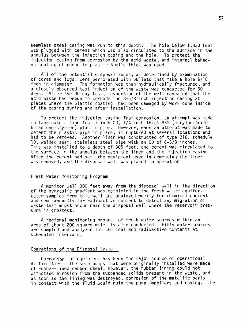
seamless steel casing was run to this depth. The hole below 1,830 feet was plugged with cement which was also circulated to the surface in the annulus between the injection casing and the hole. To protect the injection casing from corrosion by the acid waste, and internal baked- on coating of phenolic plastic 8 mils thick was used.
All of the potential disposal zones, as determined by examination of cores and logs, were perforated with bullets that make a hole 9/16 inch in diameter. The formation was then hydraulically fractured, and a closely observed test injection of the waste was conducted for 90 days. After the 90-day test, inspection of the well revealed that the acid waste had begun to corrode the 8-5/8-inch injection casing at places where the plastic coating had been damaged by work done inside of the casing during and after installation.
To protect the injection casing from corrosion, an attempt was made to fabricate a line from 7-inch-0D, 1/4-inch-thick ABS (acrylonitrile- butadiene-styrene) plastic pipe. However, when an attempt was made to cement the plastic pipe in place, it ruptured at several locations and had to be removed. Another liner was constructed of type 316, schedule 10, welded seam, stainless steel pipe with an 0D of 6-5/8 inches.This was installed to a depth of 905 feet, and cement was circulated to the surface in the annulus between the liner and the injection casing. After the cement had set, the equipment used in cementing the liner was removed, and the disposal well was placed in operation.
Fresh Water Monitoring Program
A monitor well 300 feet away from the disposal well in the direction of the hydraulic gradient was completed in the fresh water aquifer.Water samples from this well are analyzed weekly for chemical content and semi-annually for radioactive content to detect any migration of waste that might occur near the disposal well where the reservoir pressure is greatest.
A regional monitoring program of fresh water sources within an area of about 200 square miles is also conducted. Fifty water sources are sampled and analyzed for chemical and radioactive contents at scheduled intervals.
Operations of the Disposal System
Corrosion of equipment has been the major source of operational difficulties. The sump pumps that were originally installed were made of rubber-lined carbon steel; however, the rubber lining could not withstand errosion from the suspended solids present in the waste, and as soon as the lining was destroyed, corrosion of the metallic parts in contact with the fluid would ruin the pump impellers and casing. The

58
sump pumps were therefore replaced with pumps made of type 316 stainless steel, and the well delivery pump was also changed from rubber-lined carbon steel to stainless.
The rubber lining of the 12-inch delivery pipe was damaged at a flange connection. Fluid entering the annulus between the rubber lining and pipe corroded the pipe to the extent that it became necessary to replace a 100-foot damaged section. When the corroded section of the delivery pipe was replaced, a 1/8-inch-thick layer of fungus coating the rubber lining was discovered. This discovery explained, in part, a slow decrease in injectivity that had been observed for 12 months. A treatment was commenced with 3 barrels of formaldehyde for control. The formaldehyde treatment was continued until a more economical fungicide was found.
Severe losses of injectivity were also caused by corrosion of the injection casing below the stainless-steel liner. Caving and sloughing of this casing have caused restrictions to the flow of waste through the wellbore. Remedial work on the well was required to remove the obstructions and clean the well of products of corrosion.
The original objective of the disposal well was attained. The tailing pond is kept as small as practicable by use of the disposal well, and this in turn keeps seepage losses at a minimum.
Company B
Waste
Although this is a chemical manufacturing company, it was selected for detailed presentation because a part of the waste does originate from mining operations. The remainder is a highly corrosive hydrochloric acid waste that may be encountered in leaching operations or in the processing of mined minerals.
The plant operation can be divided into three distinct parts which are interdependent for overall economic operation: (1) Mining, brine purification, and disposal of tailings into a shallow well; (2) inorganic preparations where the brine is electrolyzed to produce hydrogen, chlorine, and sodium hydroxide; and (3) the organic division which uses large quantities of chlorine for the chlorination of methane, ethane, propane, benzene, phenol, and acetic acid.
Mined salt is diluted with water and treated for removal of magnesium and magnesium hydroxide. The magnesium hydroxide is diluted with water, acidified to insure solution, and then saturated with salt to form a waste stream amounting to 200 gallons per minute which is injected into a 400-foot-deep well. This well is bottomed into a porous section of a salt formation. The waste is saturated with salt before disposal to prevent it from dissolving formation salt and forming caverns.

59
The electrolytic process waste as follows:
1. Sulfuric acid, used to remove water from the hydrogen and chlorine. The "spent" sulfuric acid from hydrogen and chloring dryingis sold whenever it can be marketed or is discharged into a pond for partial neutralization and dilution before entering the sump (Figure 7).
2. Bromine, a contaminant of the chlorine. The chlorine is purified by liquefying the gas stream and then distilling it. The bottoms from the still containing about 75 percent bromine and 25 percent chlorine are treated with caustic and discharged to the sump. There is no market for the impure bromine produced in this plant, and the amount presentis too small to allow economic purification for sale; therefore, this waste is a constant constituent of the varying waste mixture going to the deep disposal well.
3. Chlorine-saturated water from the electrolytic cells.
4. Wash water from tank cars (for transportation of caustic and chlorine) and from the chlorine concentrating plant and electrolytic cells, which are washed every 72 hours to remove accumulated salt cake from the vessels.
In the preparation of chlorinated hydrocarbons, large quantities of hydrogen chloride are made as a byproduct. The hydrogen chloride is sold as an anhydrous product or as various grades of hydrochloric acid, but the market for this product fluctuates over wide extremes. Because the storage capacity at the plant is limited, there are periods of operation when large excesses of hydrogen chloride must be disposed as a waste product, causing a pH change of the waste collected in the sump from 9 to 1 and back again to 9 within 24 hours.
Besides these waste streams, the water from rainfall is trapped and channeled into the subsurface waste disposal system. This is done because of the high concentration of salts, caustic, and acids that are present on the ground in the plant from spills in the inorganic plant area and loading platforms.
Surface Equipment
The layout and size of the surface equipment is illustrated in Figure 7. During normal operation, waste from the various plant streams enters the sump where a portion of suspended solids are removed by passages of the waste over two weirs. The flow of waste from the sump to the well is governed by two automatic throttling valves and an air-bubble, liquid-level, sensing device that opens first one valve and then the other if the level of the waste in the sump exceeds a preset maximum. When the liquid level in the sump reaches a preset minimum, the control circuit will shut both valves, preventing air from entering the well.

Overflow dike
FIG U R E 7 .-S u rfa c e Equipment-Company B.

61
A 6-inch, steel-jacketed, polyethylene pipe is used for delivery of the waste from the control vlave to the wellhead. The pipe is steel jacketed to protect it from the detrimental effect of water hammer. When the well is shut down for repair, the waste is accumulated in an asphalt-lined retention pond that is capable of holding an 8-day waste effluent under normal operating conditions. If the well is inoperable for more than 8 days, the units producing the acid waste solution are shut down, and the neutral solutions are handled by the shallow well.
All storm sewers drain into the surface drainage ditch which then empties into the waste disposal well through a flow-control valve.
Disposal Well Design and Geology
The shallow well (400 feet deep) was completed in 1952 because State health authorities objected to solar evaporation of waste inorganic solution from 35 ponds on the plant site. The health authorities suggested a disposal well, and the shallow well was adequate for the waste produced until 1957, when the size of the inorganic plant was doubled and the organic division was constructed. Because the waste would contain varying amounts of organics, as well as hydrochloric acid, permission was secured to dispose of the combined inorganic and organic plant waste by injection into a vugular carbonate formation that was known to lie at a depth of about 4,000 feet. This would free the shallow well for disposal of liquid mine wastes and for use in emergency.
The deep well was placed in operation in 1957, but 4 years later it failed to accept the waste. A drilling rig was brought in to rework the well. The drillers found that the casing was corroded, and that a large section had collapsed; rejuvenation of the well was hopeless.The well was plugged with cement, and a second deep well was drilled 150 feet from the first.
The details of design of the shallow well and the first deep disposal well were not obtained; therefore, the remainder of this paper is confined to the second disposal well.
Fresh water sands which are used by farmers and industries in the area were encountered to a depth of 100 feet. Below the fresh water aquifers, impermeable layers of shale and limestone (shown in Figure 8) were fround to a depth of 3,927 feet where a very porous, vugular carbonate formation containing impotable brine was found. This is a well- known, very extensive formation underlying two States. The alternating layers of shale and limestone that overlie the disposal formation furnish an excellent cap for protection of the fresh water aquifers.
Design of the disposal well is illustrated in Figure 8. Surface casing 10-3/4-inch 0D, was set to a depth of 395 feet in a 15-inch

62
Wast e
Floor of well cel ler
D r i l l hole, I 5 —inchCasing, 10^ - inch
Dr i II ho le , 9 — inch
Casing , 7 - i n c h
Tub ing , 4 — inch
Ac id re s i s ten t cement
Pe r fo ra tedsect ion
,000
'— — — ~ — — ----- 1,5 0 0
Depth, feet 0
)
-- 2,000
----- 2 ,500
-----3 , 0 0 0
:— -3 -^ 2 3 ,500
----- 4 ,000
Freshwater
Vugularcarbonateformation
FIGURE 8.-Disposal Well Design and Geo logy- Company B.

63
diameter hole, and cement was circulated to the surface in the annulus between the casing and the wellbore to protect the fresh water-bearing sands. A 3,965-foot-long string of internally plastic-coated, 7-inch- OD casing with a 157-foot section of uncoated 7-inch casing on the bottom was set and cemented in the 9-inch hole. A total of 48 feet of the bare casing were perforated with four 1/2-inch-diameter holes per foot at locations of greatest porosity, determined by visual examination of cores from the vugular carbonate formation.
A string of 4-1/2-inch-OD fibercast tubing was set to 3,994 feet with a packer at about 3,900 feet. The annulus above the packer was filled with oil.
The drilling operations were completed without loss of circulation, indicating that no large solution channel existed between the first deep disposal well and the new one.
The cost of drilling and completion of the second deep disposal well was $30,000. Tubing and surface equipment costs were approximately $40,000.
Fresh Water Monitoring Program
Two monitor wells were drilled into the fresh water aquifer. One is located 1,000 feet from the disposal-well, and the other is 1,800 feet from the well along the hydraulic gradient of the fresh water aquifer. Water from the monitor wells is examined periodically for chemical composition. If any contamination of the fresh water should occur, it ought to cause a large increase in the chloride concentration of the water from the nearest monitor well and then appear in the second well. No change in the chemical analysis of the fresh water aquifers has been detected.
Operations of the Disposal System
The annulus between the injection tubing and the injection casing (Figure 8) is filled with diesel oil. The pressure in the annulus is monitored with a continuous recorder as well as the wellhead vacuum in order that a leak can be detected quickly. An operator checks the operation of the well once every 4 hours. If the operator should note a drop in annulus pressure, he is under orders to call his supervisor immediately.
Operation of the seond disposal well was commenced in 1961 with a caustic waste solution flowing at 300 gpm at a wellhead vacuum and an annulus pressure of 38 psi. The well operated for 2 days with continually decreasing flow rates until the tubing vacuum was lost and flow cound not be maintained. The well was treated with acid waste, shut in for 24 hours, and then returned to service. The input rate was again above 300 gpm. The fluid flowing to the well was purposely
64
maintained very acid for the next week. Then the full disposal stream was allowed to enter the basin, and since then the well has accepted the fluid.
The operation of this chemical plant is completely dependent on the successful operation of the deep disposal well. The company has no other way to dispose of this extremely corrosive and chemically variable waste. The first well was lost because no fluid was maintained in the annulus between the tubing and injection casing, and there was no rigid observation of the operation of the well. However, the second disposal well has been improved in design, and its operation is observed closely. It has met all of the requirements of the plant for waste disposal and has capacity for handling an increase in liquid waste that is anticipated from a planned expansion of the organic division.

REFERENCES CITED
1. Bernard, George G. Effect of Reactions Between Interstitial andInjected Waters on Permeability of Rocks. Producers Monthly, December 1955, p. 26.
2. Donaldson, Erie C. Subsurface Disposal of Industrial Wastes inthe.United States. BuMines Inf. Circ. 8212, 1961, 34 pp.
3. Ives, Robert E., and Gerald E. Eddy. Subsurface Disposal ofIndustrial Wastes. Interstate Oil Compact Commission, P. 0. Box 53127, Oklahoma City, Oklahoma, 73105, June 1968, 109 pp.
4. Veir, Bryon B. Celanese Deep Well Disposal Practices. Proc. 7thInd. Water and Waste Conf., Univ. of Texas, June 1 and 2, 1967, pp. 111-125.
5. Warner, Don L. Deep-Well Disposal of Industrial Wastes. Chem.Eng,, vol. 72, No. 1, January 4, 1965, p. 73.
6. Watkins, J. Wade. New Trends in Treating Waters for Injection.World Oil, vol. 146, no. 1, January 1958, p. 143.