DEEP SEA ELECTRONICS PLC - Generator Parts - Generator Ends and
20
703 Operating Instructions Issue Beta1 25/08/2003 2:45 PM JR - 1 - DEEP SEA ELECTRONICS PLC 703 AUTOMATIC START MODULE OPERATING INSTRUCTIONS Author:- John Ruddock
Transcript of DEEP SEA ELECTRONICS PLC - Generator Parts - Generator Ends and

703 Operating Instructions Issue Beta1 25/08/2003 2:45 PM JR - 1 -
DEEP SEA ELECTRONICS PLC
703 AUTOMATIC START MODULE
OPERATING INSTRUCTIONS
Author:- John Ruddock

703 Operating Instructions Issue Beta1 25/08/2003 2:45 PM JR - 2 -
<< This page is intentionally blank >>

703 Operating Instructions Issue Beta1 25/08/2003 2:45 PM JR - 3 -
TABLE OF CONTENTS
1 DESCRIPTION OF OPERATION ..........................................................4 1.1 MANUAL MODE OPERATION ........................................................................ 4 1.2 AUTOMATIC MODE OF OPERATION ............................................................ 5 1.3 WARNINGS ...................................................................................................... 6 1.4 SHUTDOWNS................................................................................................... 6
2 CONFIGURATION INSTRUCTIONS.....................................................7
3 CONFIGURATION TABLES .................................................................8
4 TERMINAL DESCRIPTION................................................................. 11
5 SPECIFICATION ................................................................................. 12
6 SOLID STATE OUTPUTS ................................................................... 13 6.1 TYPICAL CONNECTIONS ............................................................................. 13
7 ADDING A LOAD TRANSFER OUTPUT............................................ 14 7.1 CONNECTION DETAILS................................................................................ 14 7.2 DESCRIPTION................................................................................................ 14 7.3 CONFIGURATION DETAILS ......................................................................... 14
8 DIMENSIONS ...................................................................................... 15
9 TYPICAL CONNECTIONS .................................................................. 15

703 Operating Instructions Issue Beta1 25/08/2003 2:45 PM JR - 4 -
1 DESCRIPTION OF OPERATION 1.1 MANUAL MODE OPERATION
To initiate a start sequence in MANUAL, press the pushbutton, and the start sequence is initiated.
NOTE:- There is no Start Delay in this mode of operation. If the pre-heat output option is selected this timer is then initiated, and the auxiliary output selected is energised. After the above delay the Fuel Solenoid is energised, then the Starter Motor is engaged. The engine is cranked for a 10-second period. If the engine fails to fire during this cranking attempt then the starter motor is disengaged for a 10-second period. Should this sequence continue
beyond the 3 starting attempts, the start sequence will be terminated and Fail to Start fault will be illuminated. When the engine fires, the starter motor is disengaged and locked out at 20 Hz measured from the Alternator output. Rising oil pressure can also be used to disconnect the starter motor, however it cannot be used for underspeed or overspeed detection. After the starter motor has disengaged, the Safety On timer is activated (which is fixed at 12 seconds), allowing Oil Pressure, High Engine Temperature, Under-speed, Charge Fail and any delayed Auxiliary fault inputs to stabilise without triggering the fault.
Selecting STOP de-energises the FUEL SOLENOID, bringing the generator to a stop.
NOTE:- The safety on time (used for delayed alarms) is pre set to 12 seconds and can not be changed.

703 Operating Instructions Issue Beta1 25/08/2003 2:45 PM JR - 5 -
1.2 AUTOMATIC MODE OF OPERATION
This mode is activated by pressing the Auto pushbutton. An LED indicator beside the button confirms this action. The start sequence is initiated when the remote start input is activated. To allow for false remote start signals, the Start Delay timer is initiated. After this delay, if the pre-heat output option is selected then the pre-heat timer is initiated, and the corresponding auxiliary output (if configured) will energise.
NOTE: - If the Remote Start signal is removed during the Start Delay timer, the unit will return to a stand-by state. After the above delays the Fuel Solenoid is energised, then one second later, the Starter Motor is engaged. The engine is cranked for a 10-second period. If the engine fails to fire during this cranking attempt then the starter motor is disengaged for a 10-second rest period. Should this sequence continue beyond the 3 starting attempts, the start sequence will be terminated and
Fail to Start fault will be illuminated. When the engine fires, the starter motor is disengaged and locked out at 20 Hz measured from the Alternator output. Rising oil pressure can also be used to disconnect the starter motor, however it cannot be used for underspeed or overspeed detection. After the starter motor has disengaged, the Safety On timer is activated, allowing Oil Pressure, High Engine Temperature, Under-speed, Charge Fail and any delayed Auxiliary fault inputs to stabilise without triggering the fault. Once the engine is running, the output Generator Running is activated if it has been configured. On removal of the Remote Start signal the Stop delay timer is initiated. Once this timer has expired the Fuel Solenoid is de-energised, bringing the generator to a stop.
NOTE: - The safety on time (used for delayed alarms) is pre set to 12 seconds and can not be changed.

703 Operating Instructions Issue Beta1 25/08/2003 2:45 PM JR - 6 -
1.3 WARNINGS Warnings are used to warn the operator of an impending fault BATTERY CHARGE FAILURE, if the module does not detect a voltage from the warning light terminal on the auxiliary charge alternator, the icon will illuminate. (Either 8 Volts or 16 Volts, depending on the configuration of Nominal DC Voltage). Inputs 1 and 2 can be configured as warnings or shutdowns. The relevant icon will be illuminated when the input is active 1.4 SHUTDOWNS Shutdowns are latching and stop the Generator. The alarm must be cleared, and the fault removed to reset the module. In the event of a shutdown the appropriate icon will be illuminated
NOTE: - The alarm condition must be rectified before a reset will take place. If the alarm condition remains it will not be possible to reset the unit (The exception to this is the Low Oil Pressure alarm and similar ‘delayed alarms’, as the oil pressure will be low with the engine at rest). Any subsequent warnings or shutdowns that occur will be displayed steady, therefore only the first-up shutdown will appear flashing.
NOTE: - The safety on time (used for delayed alarms) is pre set to 12 seconds and can not be changed. FAIL TO START, if the engine does not fire after the pre-set 3 attempts at starting, a shutdown will be initiated. The icon will illuminate. LOW OIL PRESSURE, if the module detects that the engine oil pressure has fallen below the low oil pressure switch after the Safety On timer has expired, a shutdown will occur. The icon will illuminate. HIGH ENGINE TEMPERATURE if the module detects that the engine coolant temperature has exceeded the high engine temperature switch after the Safety On timer has expired, a shutdown will occur.
The icon will illuminate. OVERSPEED, if the engine speed exceeds the pre-set trip (14% above the nominal frequency) a shutdown is initiated. Overspeed is not delayed, it is an immediate shutdown.
The icon will illuminate.
NOTE:- During the start-up sequence the overspeed trip level is extended to 24% above the normal frequency for the duration of the safety timer to allow an extra trip level margin. This is used to prevent nuisance tripping on start-up. UNDERSPEED, if the engine speed falls below the pre-set trip (20% of the nominal frequency) after the Safety On timer has expired, a shutdown is initiated.
The icon will illuminate. Inputs 1 and 2 can be configured as warnings or shutdowns. The relevant icon will be illuminated when the input is active

703 Operating Instructions Issue Beta1 25/08/2003 2:45 PM JR - 7 -
2 CONFIGURATION INSTRUCTIONS
? With the unit in Stop mode, Configuration Mode is selected by operation of a small switch on the rear, left-hand edge of the PCB. This is partially hidden to prevent accidental operation.
? Once Configuration Mode is selected, the ‘Auto’ LED will commence rapid flashing, and all
normal operation is suspended.
? The Stop pushbutton can be used to select the LED ‘code’ that corresponds to the required function. The 5 left-hand LED’s will form the code. See configuration table over leaf.
? The Manual pushbutton will allow the user to change the associated value. The 3 right-hand LED’s inform the user of the current setting for the chosen function. See configuration table over leaf.
? When the required parameters are displayed, pressing the Auto button will save the new setting, and the process is repeated for each function change.
? When configuration is complete, the Configuration Mode Selector Switch should be returned
to the ‘Normal’ position.
Parameter Value
Normal
Configuration

703 Operating Instructions Issue Beta1 25/08/2003 2:45 PM JR - 8 -
3 CONFIGURATION TABLES
FUNCTIONS AND CONFIGURATION TABLE Function ! 1 ! 2 Value (Default in Bold)
? ? ? 0 Seconds ? ? ? 5 Seconds ? ? ? 10 Seconds ? ? ? 15 Seconds ? ? ? 20 Seconds ? ? ? 30 Seconds ? ? ? 60 Seconds
Pre-heat Timer ? ? ? ? ?
? ? ? 180 Seconds Used to pre-heat the engine prior to cranking. The output is active for the duration of the setting, prior to cranking.
? ? ? 0 Seconds ? ? ? 5 Seconds ? ? ? 10 Seconds ? ? ? 15 Seconds ? ? ? 20 Seconds ? ? ? 30 Seconds ? ? ? 60 Seconds
Start Delay ? ? ? ? ?
? ? ? 180 Seconds Used to give a delay between activating the remote start input and actually starting the engine.
? ? ? 0 Seconds ? ? ? 5 Seconds ? ? ? 10 Seconds ? ? ? 15 Seconds ? ? ? 20 Seconds ? ? ? 30 Seconds ? ? ? 60 Seconds
Stop Delay ? ? ? ? ?
? ? ? 180 Seconds Used to give a delay between deactivating the remote start input and actually stopping the engine.
? ? ? 0 Seconds ? ? ? 5 Seconds ? ? ? 10 Seconds ? ? ? 15 Seconds ? ? ? 20 Seconds ? ? ? 30 Seconds ? ? ? 60 Seconds
Energise to Stop Hold Timer
? ? ? ? ?
? ? ? 180 Seconds Used for the control of the engine stop solenoid. When the engine is to be stopped, the Energise To Stop output becomes active, closing the stop solenoid (fuel valve). When the engine comes to rest, the stop solenoid will remain energised for the period of the Energise To Stop Timer, to ensure the engine has come to a complete stop.
? ? ? 50 Hz (O/S +14% / Overshoot +24%)
Nominal Frequency ? ? ? ? ?
? ? ? 60 Hz (O/S +14% / Overshoot +24%)
The systems nominal frequency. Either 50 Hz or 60 Hz
? ? ? 12V DC (CF 8V) Nominal DC Voltage ? ? ? ? ? ? ? ? 24V DC (CF 16V)
The generator battery voltage. Either 12 Volts or 24 Volts. It is used for the charge alternator failure level.
? ? ? Close on Fault LOP Switch Contact ? ? ? ? ? ? ? ? Open on Fault
Configuration for the oil pressure switch. Either to close to battery negative on a fault, or open on a fault.

703 Operating Instructions Issue Beta1 25/08/2003 2:45 PM JR - 9 -
FUNCTIONS AND CONFIGURATION TABLE
Function ! 1 ! 2 Value (Default in Bold) ? ? ? Close on Fault HET Switch Contact ? ? ? ? ? ? ? ? Open on Fault
Configuration for the coolant temperature switch. Either to close to battery negative on a fault, or open on a fault.
? ? ? Disabled Crank disconnect on Oil Pressure
? ? ? ? ?
? ? ? Enabled (2 Second Delay)
If this is enabled, the starter motor will disconnect 2 seconds after the oil pressure switch detects oil pressure. NOTE:- Not suitable for all generators, due to the different monitoring points on lubrication systems.
? ? ? Disabled Underspeed Detection
? ? ? ? ? ? ? ? Enabled (U/S –20%)
If this is enabled, the unit will shut down the generator if the frequency falls below 20% of the nominal frequency.
? ? ? Immediate Warning Close on Fault
? ? ? Immediate Warning Open on Fault
? ? ? Immediate Shutdown Close on Fault
? ? ? Immediate Shutdown Open on Fault
? ? ? Delayed Warning Close on Fault
? ? ? Delayed Warning Open on Fault
? ? ? Delayed Shutdown Close on Fault
Auxiliary Input 1 Function
? ? ? ? ?
? ? ? Delayed Shutdown Open on Fault
Programmable input, can be configured to on of the following ? Immediate warning close on fault – If the input is activated at any time the unit will alarm and energise the
common warning and common alarm output. ? Immediate warning open on fault – If the input is deactivated at any time the unit will alarm and energise the
common warning and common alarm output. ? Immediate shutdown close on fault – If the input is activated at any time the generator will be shutdown and
energise the common warning and common shutdown output. The generator can not be started. ? Immediate shutdown open on fault – If the input is deactivated at any time the generator will be shutdown and
energise the common warning and common shutdown output. The generator can not be started. ? Delayed warning close on fault – If the input is activated and the saftey time has elapsed the unit will alarm and
energise the common warning and common alarm output. ? Delayed warning open on fault – If the input is deactivated and the saftey time has elapsed the unit will alarm and
energise the common warning and common alarm output. ? Delayed shutdown close on fault – If the input is activated and the saftey time has elapsed the generator will be
shutdown and energise the common warning and common shutdown output. ? Delayed shutdown open on fault – If the input is deactivated and the saftey time has elapsed the generator will be
shutdown and energise the common warning and common shutdown output.

703 Operating Instructions Issue Beta1 25/08/2003 2:45 PM JR - 10 -
FUNCTIONS AND CONFIGURATION TABLE
Function ! 1 ! 2 Value (Default in Bold)
? ? ? Immediate Warning Close on Fault
? ? ? Immediate Warning Open on Fault
? ? ? Immediate Shutdown Close on Fault
? ? ? Immediate Shutdown Open on Fault
? ? ? Delayed Warning Close on Fault
? ? ? Delayed Warning Open on Fault
? ? ? Delayed Shutdown Close on Fault
Auxiliary Input 2 Function
? ? ? ? ?
? ? ? Delayed Shutdown Open on Fault
Programmable input, can be configured to on of the following ? Immediate warning close on fault – If the input is activated at any time the unit will alarm and energise the
common warning and common alarm output. ? Immediate warning open on fault – If the input is deactivated at any time the unit will alarm and energise the
common warning and common alarm output. ? Immediate shutdown close on fault – If the input is activated at any time the generator will be shutdown and
energise the common warning and common shutdown output. The generator can not be started. ? Immediate shutdown open on fault – If the input is deactivated at any time the generator will be shutdown and
energise the common warning and common shutdown output. The generator can not be started. ? Delayed warning close on fault – If the input is activated and the saftey time has elapsed the unit will alarm and
energise the common warning and common alarm output. ? Delayed warning open on fault – If the input is deactivated and the saftey time has elapsed the unit will alarm and
energise the common warning and common alarm output. ? Delayed shutdown close on fault – If the input is activated and the saftey time has elapsed the generator will be
shutdown and energise the common warning and common shutdown output. ? Delayed shutdown open on fault – If the input is deactivated and the saftey time has elapsed the generator will be
shutdown and energise the common warning and common shutdown output.
? ? ? Not used ? ? ? Pre-heat ? ? ? Engine Running ? ? ? Common Warning ? ? ? Common Shutdown ? ? ? System in Auto ? ? ? Common Alarm
Auxiliary Output 1 Function
? ? ? ? ?
? ? ? Energise to Stop Programmable output can be configured to one of the following. ? Pre-heat. - The output is energised for the period of pre-heat time prior to cranking, and between the cranking
attempts. ? Engine Running. - The output is active after the saftey timer has elapsed. ? Common warning. - The output is active if there are any warning alarm active. ? Common shutdown - The output is active if there are any shutdown alarms active. ? System in auto. - The output is active when the system is in automatic mode. ? Common Alarm. - The output is active if there is any alarm condition. ? Energise to stop. - The output is energised when the engine is required to stop (normal or fault conditions), and
will remain energised for the period of the Energise To Stop Timer, to ensure the engine has come to a complete stop.

703 Operating Instructions Issue Beta1 25/08/2003 2:45 PM JR - 11 -
FUNCTIONS AND CONFIGURATION TABLE
Function ! 1 ! 2 Value (Default in Bold) ? ? ? Not used ? ? ? Pre-heat ? ? ? Engine Running ? ? ? Common Warning ? ? ? Common Shutdown ? ? ? System in Auto ? ? ? Common Alarm
Auxiliary Output 2 Function
? ? ? ? ?
? ? ? Energise to Stop Programmable output can be configured to one of the following. ? Pre-heat. - The output is energised for the period of pre-heat time prior to cranking, and between the cranking
attempts. ? Engine Running. - The output is active after the saftey timer has elapsed. ? Common warning. - The output is active if there are any warning alarm active. ? Common shutdown - The output is active if there are any shutdown alarms active. ? System in auto. - The output is active when the system is in automatic mode. ? Common Alarm. - The output is active if there is any alarm condition. ? Energise to stop. - The output is energised when the engine is required to stop (normal or fault conditions), and
will remain energised for the period of the Energise To Stop Timer, to ensure the engine has come to a complete stop.
4 TERMINAL DESCRIPTION
PIN No
DESCRIPTION CABLE SIZE
NOTES
1 DC Plant Supply Input (-ve)
1.0mm Connected to plant battery negative
2 DC Plant Supply Input (+ve)
1.0mm Connected to plant battery positive (Recommended Fuse 2A)
3 Fuel relay Output 1.0mm Used to operate the fuel relay. 4 Start relay Output 1.0mm Used to operate the cranking relay. 5 Auxiliary Output relay 1 1.0mm Configurable output. 6 Auxiliary Output relay 2 1.0mm Configurable output. 7 Charge Fail Input/ Excitation
Output 1.0mm Must NOT be connected to plant supply
negative if not used. 8 Low Oil Pressure Input 0.5mm Switch to negative. 9 High Engine Temp Input 0.5mm Switch to negative. 10 Auxiliary Input 1 0.5mm Switch to negative. 11 Auxiliary Input 2 0.5mm Switch to negative. 12 Remote Start Input 0.5mm Switch to negative. 13 Not Used 14 Not Used 15 Functional Earth 1.0mm Connect to a good clean earth point 16 Not Used 17 Not Used 18 Not Used 19 Not Used 20 Alternator Input L1 1.0mm Do not connect if not used. (2A Fuse) 21 Alternator Input N 1.0mm Do not connect if not used.
NOTE:- All the outputs are solid state, rated at 1.2 Amps 8 Volts to 35 Volts DC, and switch to battery negative when active.

703 Operating Instructions Issue Beta1 25/08/2003 2:45 PM JR - 12 -
5 SPECIFICATION
DC Supply: 8 Volts to 35 Volts DC Continuous. Cranking Dropouts: Able to survive 0 Volts for 50 mS, providing supply was at
least 10 V before dropout and supply recovers to 5 Volts. This is achieved without the need for internal batteries.
Max. Current: Operating 50mA Standby 10mA
Alternator Input Range: 75 Volts (ph-N) to 277 Volts (ph-N) AC (+20%) Alternator Input Frequency: 50 - 60 Hz at rated engine speed
(Minimum: 75V AC Ph-N) (Crank Disconnect from 15V Ph-N @ 20Hz) Overspeed +14% (+24% overshoot) Underspeed –20%
Start Output: 1.2 Amp DC at supply voltage. Fuel Output: 1.2 Amp DC at supply voltage.
Auxiliary Outputs: 1.2 Amp DC at supply voltage. Dimensions: 125mm x 165mm x 28 mm Charge Fail: 12 Volts = 8 Volts CF 24 Volts = 16 Volts CF
Operating Temperature Range: -30?C to + 700C Applicable Standards
Compliant with BS EN 60950 Low Voltage Directive Compliant with BS EN 50081-2: 1992 EMC Directive Compliant with BS EN 61000-6-4: 2000 EMC Directive
Compliance to European Legislation
Registered Component for USA & Canada
Deep Sea Electronics plc reserve the right to change specification without notice.

703 Operating Instructions Issue Beta1 25/08/2003 2:45 PM JR - 13 -
6 SOLID STATE OUTPUTS DSE’s utilisation of Solid State Outputs gives many advantages, the main points being: ? No Moving Parts ? Fully Overload / Short Circuit Protected. ? Smaller dimensions hence lighter, thinner and cheaper than conventional relays. ? Less power required making them far more reliable. The main difference from conventional outputs is that solid state outputs switch to negative (–ve) when active. This type of output is normally used with an automotive or plug in relay. 6.1 TYPICAL CONNECTIONS
Battery positive (+)
Solid state output from DSE module
eg. Terminal 3 of 703/4 - FUELFuel Solenoid (+ terminal)
* Observe polarity when using relays fitted with integral diodes!
*
A D
B C
Solid State Output from DSE Module Pin
Automotive relay Pin
8 Pin Plugin relay Function
3 86 7 Fuel Output 85 2 To Positive supply via fuse 30 1 To Positive supply via fuse
A B C D 87 3 To Fuel Solenoid
Example of relay pins connected to DSE solid state output to drive a fuel solenoid.
See section on Typical Connections else where in this manual for overall typical wiring diagram

703 Operating Instructions Issue Beta1 25/08/2003 2:45 PM JR - 14 -
7 ADDING A LOAD TRANSFER OUTPUT
The DSE 703 is a very flexible, low cost, remote start module. It can be further enhanced by the addition of simple external wiring to ‘convert’ the Engine Running output into a Load Transfer output. This allows the 703 module to control a load-switching device, while also giving provision for a Cooling Run. 7.1 CONNECTION DETAILS
7.2 DESCRIPTION With the 703 in AUTO mode, applying the remote start signal will begin the start delay timer, after which, the engine will be called upon to start. Upon activation of the Engine Running output, the DC relay will close, switching the remote start signal through its contacts. This switched signal becomes the Load Transfer output, which can be used to drive a DC load-switching device or further slave relay if required. When the remote start signal is removed, this also removes the Load Transfer output (opening the contractor) and begins the 703’s Stop Delay timer. This acts as a cooling timer to allow the set to cool off load. When the Stop Delay timer expires, the set will be stopped.
NOTE:- The diode acts to stop any voltage from the 703’s remote start input circuitry being fed through the DC relay. 7.3 CONFIGURATION DETAILS
Auxiliary output 1 Function Engine running ? ? ? ? ? ? ? ?
Stop Delay timer Timer value
? ? ? ? ? Select as required Please see the 703 installation instructions for further details of the 703 configuration
703 remote start module
Remote start input
Engine running output Battery +ve
Load transfer output
Remote start signal ( switched to battery -ve)
DC relay
Diode

703 Operating Instructions Issue Beta1 25/08/2003 2:45 PM JR - 15 -
8 DIMENSIONS
Dimensions: 165mm x 125mm x 29mm (6.5” x 4.9” x 1.2”) Panel cut out: 149mm x 109mm (5.9” x 4.3”) Mounting Method: 4 x 4.2mm diameter holes suitable for M4 screws.
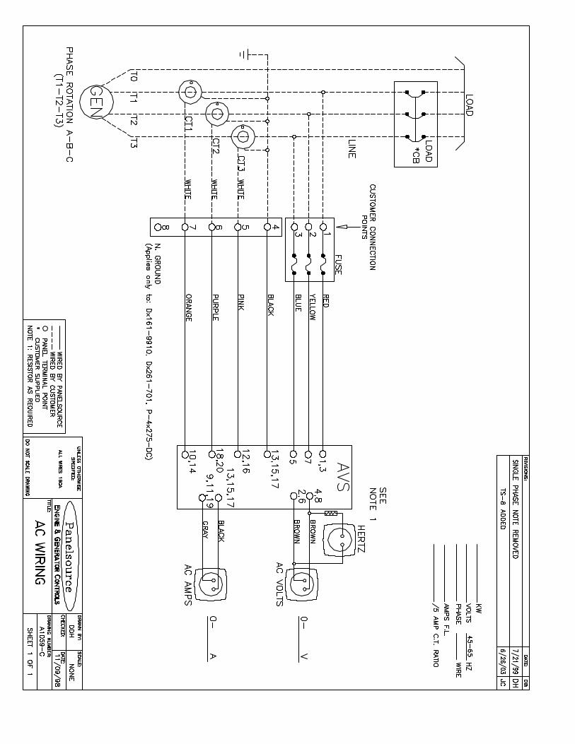
9 TYPICAL CONNECTIONS
F 2A
SSOSSOSSOSSO
SSO = Solid state outputs
= External 'Automotive' or 'Plug-in' type relays
41 2 3 5 6 7
2021
Auxiliary Outputs
++
8 9 10 11 12
Auxiliary Alarm Inputs
+
Battery
F2A F
Crank
Fuel Startermotor
Chargealt
+ +
Fuel o/p Start o/p
15
Terminals suitable for 22-16 awg (0.6mm2-1.3mm2 )field wiring Tightening Torque = 0.8N-m (7lb-in)

DEEP SEA E LE C TRONICS PLC
703Auto S ta r t
The 703 is an engine auto start and protection module. It utilizes advanced surface mount construction techniques to provide a compact, yet highly specified module. Operation is via three pushbuttons mounted on the front panel with STOP, MANUAL and AUTO positions. OPERA TION Stop mode - This is used to stop the engine when it is running and to cancel ‘Auto’ mode. It is also used to reset any Shutdown Alarm conditions. Manual mode - This mode is used to manually start and run the engine, which can be stopped by pressing the Stop button. Auto mode - This selects the automatic mode of operation, in which the module will await the remote start signal. Once received, the module will initiate its pre-configured Start Sequence, observing the start delay timer before starting the engine. When the remote start signal is removed, the module will initiate its pre-configured Stopping Sequence. The module monitors the engine and provides the following functions: � Automatic Start with 3 attempts and
Automatic Crank Disconnect - with adjustable Start and Stop Timers and Fail to Start indication.
� Configurable Pre-heat and Energize to Stop functions.
� Low Oil Pressure and High Engine Temperature Shutdown.
� Overspeed and Underspeed (frequency) protection.
� Charge Fail Alarm � Two fully configurable auxiliary
inputs. All alarms are indicated by high visibility red LED’s.
The module’s microprocessor provides a comprehensive list of timers and configurable functions. Parameter settings can be adjusted using the front panel pushbuttons once in Configuration Mode. Access to the settings is via a small ‘Configuration Switch’ on the rear of the module (see figs. 1 and 2), and enables changes to be made in the field.
Selection of the Configuration Mode is indicated by rapid flashing of the ‘Auto’ LED. The module is designed with DSE’s proven experience and uses modern construction to provide a high level of reliability and suitability for the intended operating environment. Issues such as environmental compliance and EMC have been carefully engineered into the design. Advanced features such as protected solid state outputs mean that there are no moving parts or contacts to burn-out. FE ATU RES � Micro-processor based design � Automatic Engine Starting and
Stopping � Automatic Shutdown on fault condition� Configurable via front panel � Simple pushbutton controlled
operation � Configurable Digital Inputs � Configurable Solid State Outputs � Configurable Timer Settings � Solid State Fuel and Crank outputs � External Remote Start input � LED Alarm indication � Start Delay Timer � Stop Delay Timer � Energize to Stop timer � Pre-heat Timer � Over Speed Shutdown � Optional Underspeed Protection � Low Oil Pressure Shutdown � High Engine Temp Shutdown � Optional Crank Disconnect from Oil
Pressure The 700 series modules have beendesigned for front panel mounting. The module is fitted into the cut-out, and screw holes are provided for secure fixing.
DE SC RIPTION
SP ECIF ICATI ON � DC Supply: 8 to 35 V Continuous.
� Cranking Dropouts: Able to survive 0 V for 50 mS, providing supply was at least 10 V before dropout and supply recovers to 5V. This is achieved without the need for internal batteries.
� Max. Current: Operating 50mA Standby 10mA
� Alternator Input Range: 75(ph-N) to 277(ph-N) 3 Phase 4wire AC (+20%)
� Alternator Input Frequency: 50 - 60 Hz at rated engine speed (Minimum: 75V AC Ph-N) (Crank Disconnect from 15V Ph-N @ 20 Hz) Overspeed +14% (+24% overshoot) Underspeed –20%
� Start Output: 1.2 Amp DC at supply voltage.
� Fuel Output: 1.2 Amp DC at supply voltage.
� Auxiliary Outputs: 1.2 Amp DC at supply voltage.
� Dimensions: 125 X 165 X 28 mm
� Charge Fail: 12V = 8V CF 24V = 16V CF
� Operating Temperature Range:-30 to +70° C � Compliant with BS EN 60950
Low Voltage Directive � Compliant with BS EN 50081-2
EMC Directive � Compliant with BS EN 50082-2
EMC Directive Deep Sea Electronics reserve the right to change specification without notice.
Issue 5 USA 13/06/02

F 2A
SSOSSOSSOSSO
SSO = Solid state outputs
= External 'Automotive' or 'Plug-in' type relays
41 2 3 5 6 7
2021
Auxiliary Outputs
++
8 9 10 11 12
Auxiliary Alarm Inputs
+Battery
F2A F
Crank
Fuel Startermotor
Chargealt
+ +
Fuel o/p Start o/p
15
Deep S ea E lec t r on ics p l c Highfield House, Hunmanby Industrial Estate, North Yorkshire, YO14 0PH, England Tel: +44 (0) 1723 890099 Fax: +44 (0) 1723 893303 E-mail [email protected]
CONFIGURAT ION Configuration Mode is selected by operation of a small switch on the rear, left-hand edge of the PCB. This is partially hidden to prevent accidental operation. See figs 1 and 2
Fig. 2 Diagram of reverse side of 703
Fig. 1
Configuration
Normal
125
165
4
10.85
25
109
149
Panel Cut-out: 149 x 109
114
154
TYPICA L CO NNE CTIONS
Once Configuration Mode is selected, the ‘Auto’ LED will commence rapid flashing. When in Configuration Mode all normal operation is suspended. The ‘Stop’ pushbutton can be used to select the LED ‘code’ that corresponds to the required function. The 5 left hand LED’s will form the code The ‘Manual’ pushbutton will allow the user to change the function parameters. The 3 right-hand LED’s inform the user of the current value for the chosen function. When the required parameters are displayed, pressing the ‘Auto’ button will save the new setting. The process is repeated for each function change. When configuration is complete, the Configuration Mode Selector Switch should be returned to the ‘Normal’ position. A key to all configuration options is provided (refer to Installation Instructions supplied with module).
Fig. 3 Dimensions (mm)