Deep Drawing Simulations of Tailored Blanks and ... › ws › files › 5532352 ›...
12
Deep Drawing Simulations of Tailored Blanks and Experimental Verification T. Meinders † , A. van den Berg ‡ , J. Huétink † † University of Twente, Faculty of Mechanical Engineering, P.O. box 217, 7500 AE Enschede, e-mail: [email protected] ‡ Hoogovens Research & Development, Product Application Centre, P.O. Box 10000, 1970 CA IJmuiden, e-mail: [email protected] Abstract: Tailored Blanks are increasingly used in the automotive industry. A combination of different materials, thickness, and coatings can be welded together to form a blank for stamping car body panels. The main advantage of using Tailored Blanks is to have specific characteristics at particular parts of the blank in order to reduce the material weight and costs. To investigate the behaviour of Tailored Blanks during deep drawing, the finite element code DiekA is used. In this paper, simulations of the deep drawing of two products using Tailored Blanks are discussed. For verification, the two products are stamped to gain experimental information. The correlation between the experimental results and the simulation results appears to be satisfactory. Keywords: Deep Drawing, Experiment, Simulation, Tailored Blank 1. Introduction In conventional applications, car body panels are usually made up of several smaller components. Each component is formed individually and subsequently welded together to create the desired body panel. This approach incorporates high tooling and material costs. Moreover this approach contributes to the dimensional inaccuracy in the assembly process. Therefore it is attractive to form the body panels in a single stamping by using Tailored Blanks. A Tailored Blank consists of several flat sheets that are welded together before forming. A combination of different materials, thickness, and coatings can be welded together to form a blank for stamping car body panels. The main advantage of using a Tailored Blank is to have specific characteristics at particular parts of the blank in order to reduce weight and costs. Particular parts of the blank can be made from a thicker or stronger material to increase the stiffness or strength locally whilst having thinner material at other parts. Also alternative parts of the blank can be made up of coated steel to increase the resistance to corrosion whilst having bare steel at other sections. The use of Tailored Blanks offers several other advantages with respect to product, process and design: • improvement of tolerances, since the different parts of a product are welded together before the forming operation using a continuous welding process • improvement of crash durability: more controlled greater energy absorption potential during collisions
Transcript of Deep Drawing Simulations of Tailored Blanks and ... › ws › files › 5532352 ›...

Deep Drawing Simulations of Tailored Blanks and Experimental Verification
T. Meinders†, A. van den Berg‡, J. Huétink†
† University of Twente, Faculty of Mechanical Engineering, P.O. box 217, 7500 AE Enschede, e-mail: [email protected]
‡ Hoogovens Research & Development, Product Application Centre, P.O. Box 10000, 1970 CA IJmuiden, e-mail: [email protected]
Abstract: Tailored Blanks are increasingly used in the automotive industry. A combination of different materials, thickness, and coatings can be welded together to form a blank for stamping car body panels. The main advantage of using Tailored Blanks is to have specific characteristics at particular parts of the blank in order to reduce the material weight and costs. To investigate the behaviour of Tailored Blanks during deep drawing, the finite element code DiekA is used. In this paper, simulations of the deep drawing of two products using Tailored Blanks are discussed. For verification, the two products are stamped to gain experimental information. The correlation between the experimental results and the simulation results appears to be satisfactory. Keywords: Deep Drawing, Experiment, Simulation, Tailored Blank
1. Introduction In conventional applications, car body panels are usually made up of several smaller components. Each component is formed individually and subsequently welded together to create the desired body panel. This approach incorporates high tooling and material costs. Moreover this approach contributes to the dimensional inaccuracy in the assembly process. Therefore it is attractive to form the body panels in a single stamping by using Tailored Blanks. A Tailored Blank consists of several flat sheets that are welded together before forming. A combination of different materials, thickness, and coatings can be welded together to form a blank for stamping car body panels. The main advantage of using a Tailored Blank is to have specific characteristics at particular parts of the blank in order to reduce weight and costs. Particular parts of the blank can be made from a thicker or stronger material to increase the stiffness or strength locally whilst having thinner material at other parts. Also alternative parts of the blank can be made up of coated steel to increase the resistance to corrosion whilst having bare steel at other sections. The use of Tailored Blanks offers several other advantages with respect to product, process and design:
• improvement of tolerances, since the different parts of a product are welded together before the forming operation using a continuous welding process
• improvement of crash durability: more controlled greater energy absorption potential during collisions

• reduction of the amount of scrap due to the irregular shapes of the product. Smaller pieces of materials which form an irregular blank shape can be nested easily for better material utilisation
• reduction of the number of parts to be assembled, which results in a simplification of the logistics
• reduction of (press-) handling including dies and installations • lower personnel and production costs • extension of the styling potential for product designers
Some of these advantages of Tailored Blanks can contribute to the development of lighter car design, resulting in a reduction of the fuel consumption. This is very important in view of the actual environment oriented age. Facing the advantages of Tailored Blanks also some disadvantages appear with its use. The welding of the flat sheets is an extra step in the production process with added costs; moreover the weld and the Heat Affected Zone can negatively influence the formability of the blank due to the development of martensitic structures [1], [2], [3], [4]. Tailored Blanks are increasingly used in the production of automotive products where the advantages more than make up for the disadvantages. Some examples of car components made of Tailored Blanks are:
• A, B, and C pillars, situated at both sides of the doors, see Figure 1 • Inner door panels • Longitudinals • Cross rail bumpers • Floor panels • Wheel houses • Inner panel tail gates
Figure 1. Tailored Blank for B-pillar B-pillar
However, the critical property of Tailored Blanks is the reduction of the formability due to the welding process, compared to the formability of the base materials. In section 2 of this paper attention is paid to this subject. There is also a need to understand the influence of the welding process and the weld location on the formability and the weld line motion during the forming process. Information about these items can be gained from numerical simulation using a finite element method. The set-up for these simulations is described in section 3, using the finite element code DiekA. In section 4 the experimental set-up is presented which will be used to verify the Tailored Blank simulations (section 5). Finally, several conclusions are drawn.
2. Formability of Tailored Blanks
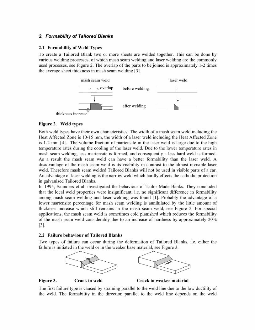
2.1 Formability of Weld Types To create a Tailored Blank two or more sheets are welded together. This can be done by various welding processes, of which mash seam welding and laser welding are the commonly used processes, see Figure 2. The overlap of the parts to be joined is approximately 1-2 times the average sheet thickness in mash seam welding [3].
Figure 2. Weld types
Both weld types have their own characteristics. The width of a mash seam weld including the Heat Affected Zone is 10-15 mm, the width of a laser weld including the Heat Affected Zone is 1-2 mm [4]. The volume fraction of martensite in the laser weld is large due to the high temperature rates during the cooling of the laser weld. Due to the lower temperature rates in mash seam welding, less martensite is formed, and consequently a less hard weld is formed. As a result the mash seam weld can have a better formability than the laser weld. A disadvantage of the mash seam weld is its visibility in contrast to the almost invisible laser weld. Therefore mash seam welded Tailored Blanks will not be used in visible parts of a car. An advantage of laser welding is the narrow weld which hardly effects the cathodic protection in galvanised Tailored Blanks. In 1995, Saunders et al. investigated the behaviour of Tailor Made Banks. They concluded that the local weld properties were insignificant, i.e. no significant difference in formability among mash seam welding and laser welding was found [1]. Probably the advantage of a lower martensite percentage for mash seam welding is annihilated by the little amount of thickness increase which still remains in the mash seam weld, see Figure 2. For special applications, the mash seam weld is sometimes cold planished which reduces the formability of the mash seam weld considerably due to an increase of hardness by approximately 20% [3].
2.2 Failure behaviour of Tailored Blanks Two types of failure can occur during the deformation of Tailored Blanks, i.e. either the failure is initiated in the weld or in the weaker base material, see Figure 3.
Figure 3. Crack in weld Crack in weaker material
The first failure type is caused by straining parallel to the weld line due to the low ductility of the weld. The formability in the direction parallel to the weld line depends on the weld

properties. The second failure type occurs by straining the Tailored Blank perpendicular to the weld line. The strain will be localised in the weaker base material since the weld has a higher flow stress than the base materials, and hence the formability in this direction depends on the weaker base material properties. In case of both failure types the press formability decreases as the weld line location moves towards critical deep drawing areas, for example product corners. This effect is stronger as the strength ratio between the base materials increases.
2.3 Deep drawing of Tailored Blanks To apply high quality Tailored Blank products in the automotive industry, it is important to understand the formability behaviour of Tailored Blanks during deep drawing. The failure types for Tailored Blanks, the influence of the weld process and weld location on the formability and the weld line motion must be investigated. Shi [5] concluded that the amount of weld movement towards the stronger material is a measure for the strain localisation in the weaker base material. This weld movement strongly depends on the strength ratio and location of the base materials, and not on the weld type and weld width. Experiments performed by Saunders et. al. [1] indeed show the performance of a Tailored Blank to depend on the amount of weld movement. Prediction of the weld movement is therefore very important to predict the press formability (strain state, failure) of a Tailored Blank. The Finite Element Method may contribute to the prediction of Tailored Blank behaviour and its manufacturability.
3. Simulation set-up To investigate the weld movement of Tailored Blanks during deep drawing, the finite element code DiekA [6] is used. A pre-processor for deep drawing of Tailored Blanks has been developed to generate input for the simulation program. The main characteristics of the strategy this pre-processor are treated in this section.
3.1 Weld modelling There are two strategies to model Tailored Blanks in a finite element program. The first strategy is to model the weld accurately. In this situation the weld type is taken into account, i.e. the dimensions and the shape of the weld, and also the volume fractions of martensite in the weld and the Heat Affected Zone are taken into account. This approach requires a fine element mesh in the weld area. The second strategy is to neglect the weld type, only the place of the weld is taken into account. In this last approach the weld and Heat Affected Zone are modelled with one row of (coarse) elements, or are simply neglected which holds that in the last option the originated martensite is not taken into account. The second model strategy can be useful for deep drawing simulations without high local deformations in the weld area [4]. Since the appearing stress states in the products treated in this paper are expected to be relatively simple, the weld itself will not be modelled in the Tailored Blank simulations.
3.2 Sheet Modelling The blanks are modelled with three-node triangular plane stress elements. Three different element types are available to simulate the deep drawing of Tailored Blanks, i.e. membrane elements, which account for membrane stresses only, Kirchhoff elements, which account for bending stresses as well and Mindlin elements, which also account for shear stresses.

Considering the geometry of the simulated products, the bending stresses and the shear stresses are expected to be inferior to the membrane stresses. Therefore it will be sufficient to use membrane elements. For contact description between the sheet and the tool special 6-node triangular contact elements are used [7], see Figure 4. The inside nodes of the contact elements (near the plate element) are connected to the plate nodes; the distance between plate node and contact node is half of the sheet thickness. The outside nodes of the contact elements will be projected on the tool surfaces. Applying these contact elements, the contact behaviour as well as the friction behaviour during the deep drawing process can be described.
Figure 4. Location of contact elements with respect to a plate element
As mentioned before, the weld itself will not be modelled but will be represented as a simple boundary condition between different base materials. This kind of modelling is illustrated in Figure 5.
Figure 5. Numerical welding of two base materials
Two base materials must be welded numerically. For a uniform blank, the plate node is the master node and the contact element nodes are slave nodes. However this approach has to be adapted for Tailored Blanks. In the above example base material 1 is chosen to be the master material. This means that the hierarchy in the element nodes is comparable to that of a uniform blank. This holds for base material 2 as well, except for the first row of element nodes. The plate nodes in this row are treated as slave nodes of the neighbouring plate nodes of base material 1. The inside nodes of the contact element (contact node) of base material 2 are also connected to the master plate nodes of base material 1. The outside nodes of the contact element (contour node) of base material 2 are connected to the contact nodes of the same material to preserve an accurate tool description.
3.3 Tool modelling Since deep drawing of Tailored Blanks differs from deep drawing of uniform blanks, the tools have to be adapted to this process, especially when base materials with a different thickness are being joined. The necessary adaptations are summarised below for each deep drawing tool, assuming different thickness of the base materials.

Blankholder A flat rigid blankholder cannot prevent wrinkling in the thinner base material during deep drawing and the blankholder force cannot be varied over the product flange. Possible adaptations to the blankholder to avoid these wrinkles are a stepped rigid blankholder, a deformable blankholder and a segmented blankholder which allows individual force control per segment [8]. A stepped rigid blankholder is only able to reduce wrinkling since, during deep drawing, the blankholder looses contact with the thinner blank due to upsetting in some regions of the flange. The deformable blankholder can prevent wrinkling, however the contact pressure is nearly constant over the entire flange. This high pressure, needed to avoid wrinkles in the stronger base material, can lead to premature necking in the thinner base material. The segmented blank holder prevents both wrinkling and premature tearing due to a variable blankholder force over the product flange. In the finite element code DiekA both the stepped and the segmented blankholder can be used. Commonly the weld line in the bottom of a product moves towards the thicker base material, resulting in a higher material flow out of the flange into the die cavity for the thinner base material. This yields a weld line motion towards the thinner base material in the product flange. To avoid damage of the blankholder during deep drawing caused by the thicker base material a tool offset between the thicker blank and tool step must be created in the blankholder, see Figure 6, which allows the thinner material to wrinkle.
Figure 6. Definition of the tool offset
Punch The punch only needs adapting if the weld is located under the punch. In that case a flat punch cannot prevent wrinkling near the weld line. A stepped punch can be the solution to this problem. However the displacement of the weld line during deep drawing may cause problems. When the weld moves towards the thinner material due to a high blankholder pressure on the thinner material, the offset between blank and tool step must be increased which permits the thinner material to wrinkle slightly. Die Two strategies can be followed to adapt the deep drawing tools for Tailored Blanks. Either both the punch and the blankholder must be adapted leaving the die unchanged, or the die has to be adapted whereas the punch and blankholder can remain as they are. Usually the outside of a product must be flat, which means that the first strategy is recommended. Consequenlty the die will not be adapted in this case.
3.4 Example of a Tailored Blank generated by the pre-processor A pre-processor has been developed to generate an input file for the used finite element program. This pre-processor enables the user to create Tailored Blanks with complex shapes and with different weld line shapes, i.e. straight or a circular weld. An example of a Tailored Blank, generated by applying the pre-processor and subsequently deformed using the finite element program, is depicted in Figure 7. The blank is assembled out of HS-steel with an

initial thickness of 1.0 mm (upper left) and 0.7 mm (mid right) and of IF-steel with an initial thickness of 1.0 mm (mid left) and 0.7 mm (right).
Figure 7. Complex Tailored Blank with circular and straight welds
4. Experimental set-up The experiments for the simple products have been performed at the Research & Development department of the Dutch company Koninklijke Hoogovens N.V.. The products have been deep drawn on a 300 tons SMG-press. Since laser welding becomes more and more important in the automotive industry, only laser welded Tailored Blanks have been stamped. The punch was adapted for the thickness deviation of the base materials. To overcome the problem of thickness deviation with respect to the blankholder, half circular rings with a different thickness have been placed between the blankholder and the thinner base material. The blankholder force was applied at four points and may have a different value for each place. The Tailored Blanks have been lubricated with machine oil Lical EP2. The coefficient of friction is estimated between 0.12 and 0.15. Three base materials have been used to create two different thickness combination for the Tailored Blanks. The material properties of these materials are listed in Table 1.
Steel I II III thickness (mm) 0.70 0.98 0.80
C 544 549 521 Rp (Mpa) 168 173 171
n 0.221 0.234 0.217 R0 1.842 1.971 1.866 R45 1.302 1.277 1.348 R90 2.077 2.114 2.049
Table 1. Material properties
5. Applications A background of Tailored Blank modelling is given in section 3 of this paper. Several possible modelling techniques are summed and also the simplifications are mentioned which are used in this paper to simulate the deep drawing of Tailored Blanks. In this section the results of the deep drawing simulations of round products are given. Two sets of simulations have been performed, incorporating the mentioned simplifications. The first set is a round product with a flat bottom, the second set is a round product with a spherical bottom. The

same sets of experiments have been performed to compare the simulation results, leading to the conclusion whether the simulations, including simplifications, gain accurate results or not. When it appears that the simulations gain accurate results, the finite element code can be used to predict the stress state, strain state and weld line motion in the Tailored Blank during deep drawing.
5.1 Round product with flat bottom The round products with a flat bottom have been pressed, using a punch with a diameter of 293 mm and a die with a diameter of 295 mm. Both the radius of the punch shoulder and the die shoulder was 20 mm. The initial blank diameter was 480 mm. A stepped blankholder has been used in the experiments. Two thickness combinations have been tested. A 1.0 mm steel was joined to a 0.7 mm steel and a 0.8 mm steel was joined to a 0.7 mm steel. Three different weld locations have been chosen, one at -130 mm of the centre of the product (left), one in the middle of the product and one at 130 mm of the centre of the product (right). Six different experiments have been performed in which the weld location and the material combination have been varied [9]. The product height depends on the thickness combination and the weld location, see Table 2. The results of the experiments and simulations of the combinations printed in bold, will be discussed in this sub section.
Thickness weld left middle right
1.0 mm - 0.7 mm 50 mm 100 mm 100 mm 0.8 mm - 0.7 mm 50 mm 100 mm 100 mm
Table 2. Product height
5.1.1 Tailored Blank comprised of a 1.0 - 0.7 mm base material combination, welded in the middle To simulate the deep drawing of this product approximately 3600 membrane elements have been used, see Figure 8. An elastic plastic material model was used and the material behaviour was assumed to be Hill anisotropic with its parameters according Table 1.
Figure 8. Element meshes of the initial and a deformed blank (flat bottom)
The simulation was stopped after 100 mm deep drawing. Comparing the calculated flange shape and weld location with the experimental results yields to the conclusion that the simulation agree well with the experiments, see Figure 9. Also the simulated weld line motion during deep drawing is depicted in Figure 9. In the bottom, the weld moves towards the

thicker material, which means that the strain is localised in the thinner base material. The total weld displacement in the entire product is only 8 mm after 100 mm deep drawing.
-250
-150
-50
50
150
250
-250 -150 -50 50 150 250
x-co-ordinate (mm)
y-co
-ord
inat
e (m
m)
experiment
simulation
punch
blank
0
50
100
150
200
250
-2 0 2 4 6 8x-co-ordinate (mm)
y-co
-ord
inat
e (m
m)
0 mm25 mm50 mm75 mm100 mm
Figure 9. Flange shape and weld movement
5.1.2 Tailored Blank comprised of a 0.8 - 0.7 mm base material combination, welded at the left side The former simulation was performed with an elastic plastic material model. Since the C.P.U. time of that calculation was considerable, this simulation has been performed with a rigid plastic material model. The simulation has been stopped after 50 mm deep drawing and again the simulation results are compared with the experiments, see Figure 10. The simulated weld location agrees well with the experimental one, the simulated flange shape deviates at some parts from the experiments. Probably this is caused by the assumed uniform blankholder pressure, which is not uniform in reality. The weld line motion during drawing in this product is much higher compared to the former product, which is caused by the non-symmetric location of the initial weld.
-250
-150
-50
50
150
250
-250 -150 -50 50 150 250
x-co-ordinate (mm)
y-co
-ord
inat
e (m
m)
experiment
simulation
punch
blank
0
50
100
150
200
-140 -130 -120 -110x-co-ordinate (mm)
y-co
-ord
inat
e (m
m)
0 mm
25 mm50 mm
Figure 10. Flange shape and weld movement

5.2 Round product with spherical bottom The round products with a spherical bottom have been pressed, using the same tool geometry as in the pressing of round products with a flat bottom, except for the spherical punch which has a nose radius of 146.5 mm. The same set of experiments was performed for this type of product [10], in which the product height depends on the thickness combination and weld location, see Table 3. The results of the experiments and simulations discussed in this sub section are printed in bold.
Thickness weld left middle right
1.0 mm - 0.7 mm 150 mm 80 mm 150 mm 0.8 mm - 0.7 mm 150 mm 100 mm 150 mm
Table 3. Product height
5.2.1 Tailored Blank comprised of a 1.0 - 0.7 mm base material combination, welded in the middle Approximately 3600 membrane elements have been used to simulate the deep drawing of this product type. Considering the calculation time, a Hill anisotropic rigid plastic material model was used instead of an elastic plastic material model. After 150 mm deep drawing the calculated flange shape and the weld location are compared to the experimental results, see Figure 11. The calculated flange shape agrees well with the experiment. However, the weld line motion during deep drawing is overestimated. After 150 mm deep drawing the deviation in weld location is 25 mm. This overestimation is due to the applied rigid plastic material model, since in this model the plastic strain is overestimated for less strained areas.
-250
-150
-50
50
150
250
-250 -150 -50 50 150 250
x-co-ordinate (mm)
y-co
-ord
inat
e(m
m)
experimentsimulationpunchblank
0
100
200
-20 -10 0 10x-co-ordinate (mm)
y-co
-ord
inat
e (m
m)
0 mm
50 mm
100 mm
150 mm
Figure 11. Flange shape and weld movement
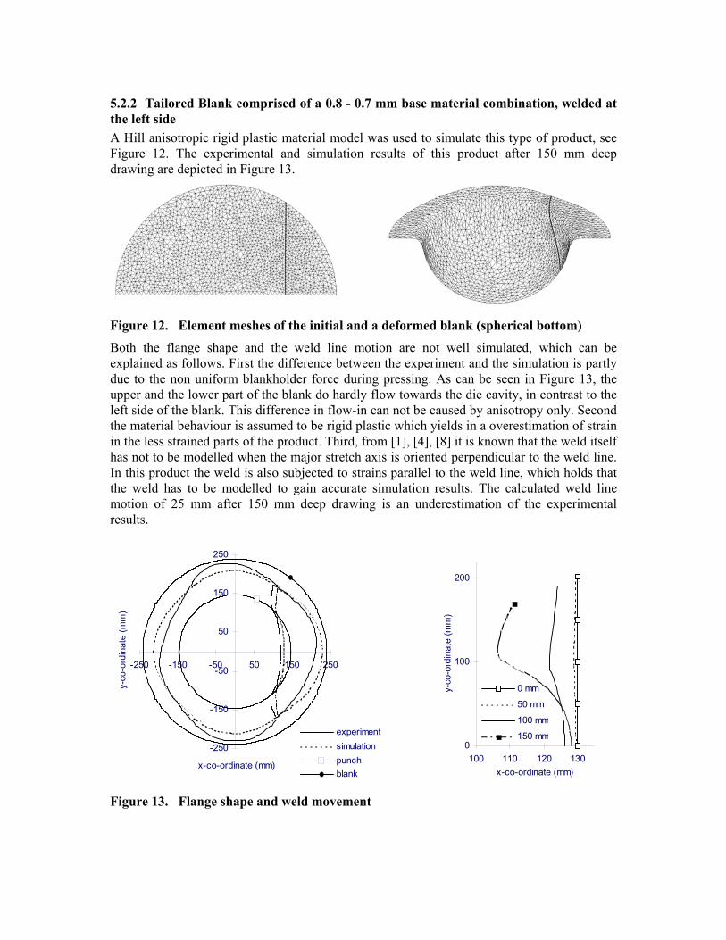
5.2.2 Tailored Blank comprised of a 0.8 - 0.7 mm base material combination, welded at the left side A Hill anisotropic rigid plastic material model was used to simulate this type of product, see Figure 12. The experimental and simulation results of this product after 150 mm deep drawing are depicted in Figure 13.
Figure 12. Element meshes of the initial and a deformed blank (spherical bottom)
Both the flange shape and the weld line motion are not well simulated, which can be explained as follows. First the difference between the experiment and the simulation is partly due to the non uniform blankholder force during pressing. As can be seen in Figure 13, the upper and the lower part of the blank do hardly flow towards the die cavity, in contrast to the left side of the blank. This difference in flow-in can not be caused by anisotropy only. Second the material behaviour is assumed to be rigid plastic which yields in a overestimation of strain in the less strained parts of the product. Third, from [1], [4], [8] it is known that the weld itself has not to be modelled when the major stretch axis is oriented perpendicular to the weld line. In this product the weld is also subjected to strains parallel to the weld line, which holds that the weld has to be modelled to gain accurate simulation results. The calculated weld line motion of 25 mm after 150 mm deep drawing is an underestimation of the experimental results.
-250
-150
-50
50
150
250
-250 -150 -50 50 150 250
x-co-ordinate (mm)
y-co
-ord
inat
e (m
m)
experimentsimulationpunchblank
0
100
200
100 110 120 130x-co-ordinate (mm)
y-co
-ord
inat
e (m
m)
0 mm
50 mm
100 mm
150 mm
Figure 13. Flange shape and weld movement

6. Conclusions • The weld line motion is significantly influenced by the occurring strain state, especially
when the material is stretched perpendicular to the weld, due to strain localisation in the thinner (weaker) base material. A minimisation of weld displacement can be achieved by placing the weld in a region with low strains perpendicular to the weld line or to choose the load bearing capacities of the applied base materials equal.
• The elastic plastic material behaviour is preferred to the rigid plastic material behaviour, since in the elastic plastic model the strains are not overestimated in low strained areas.
• The blankholder force, and hence the friction, is an important parameter in the deep drawing of Tailored Blanks. Therefore a more accurate description of the blankholder force is needed to accurately simulate Tailored Blanks.
• Probably the weld itself has to be modelled when the weld is subjected to strain states which are not predominantly perpendicular to the weld line. Further investigation must be done to verify this.
• The Finite Element Method can be used to predict the stress state, strain state and weld line motion during deep drawing, in case an elastic plastic material model is used and that the blankholder force is described accurately.
7. Acknowledgements G.J. Schotmeijer is thanked for the development of the Tailored Blank pre-processor.
8. References [1] Saunders F.I., Wagoner R.H., ‘The use of tailor-welded blanks in automotive applications’, Simulation of Materials Processing: Theory, Methods and Applications, Shen and Dawson (eds.), 1995, p.157-163 [2] Siegert K., E. Knabe, ‘Fundamental Research and Draw Die Concepts for Deep Drawing of Tailored Blanks’, ….. [3] Bouaifi B, D. Sommer, ‘Influence of joining techniques on the microstructure and formability of steel sheet’, Welding Research Abroad, vol. 42, no. 3, 1997, p.37-40 [4] Saunders F.I., Wagoner R.H., ‘Forming of Tailor-Welded Blanks’, Metallurgical and Materials Transactions A: Physical Metallurgy and Materials Science, vol. 27A, no. 9, sep. 1996, p. 2605-2616 [5] Shi M.F., K.M. Pickett, K.K.Bhatt, SAE Paper 930278, Society of Automotive Engineers, Inc. 400 Commonwealth Drive, Warrendale, PA 15096-0001, 1993 [6] DiekA manual, release 4.0 [7] Huétink J., P.T. Vreede, J. van der Lugt, ‘The simulation of contact problems in forming processes with a mixed Euler-Lagrangian FE method’, Numerical Methods in Industrial Forming Processes, E.G. Thompson, R.D. Wood, O.C. Zienkiewicz and A. Samuelsson (eds.), Colorado, 1989, p. 549-554 [8] Doege E., Dohrmann H., Kösters R., ‘Simulation and Optimization of the Forming Process of Tailored Blanks’, Proc. Numisheet’96, J.K.Lee, G.I.Kinzel and R.H.Wagoner (eds.), 1996, p.199-204 [9] Berg A van den, ‘Simulation and experiments of T.M.B.’s, part 1: round product with flat bottom’, intern report no. 88745 (in Dutch), Hoogovens R&D, 1997 [10] Berg A van den, ‘Simulation and experiments of T.M.B.’s, part 2: round product with spherical bottom’, intern report no. 88775 (in Dutch), Hoogovens R&D, 1997