Deep Dive: Virtual Chassis Fabric Best Practices Guide
36
Virtual Chassis Fabric Best Practices Guide Modified: 2017-09-15 Copyright © 2017, Juniper Networks, Inc.
Transcript of Deep Dive: Virtual Chassis Fabric Best Practices Guide

Virtual Chassis Fabric Best Practices Guide
Modified: 2017-09-15
Copyright © 2017, Juniper Networks, Inc.

Juniper Networks, Inc.1133 Innovation WaySunnyvale, California 94089USA408-745-2000www.juniper.net
Copyright © 2017 Juniper Networks, Inc. All rights reserved.
Juniper Networks, the Juniper Networks logo, Juniper, and Junos are registered trademarks of Juniper Networks, Inc. and/or its affiliates inthe United States and other countries. All other trademarks may be property of their respective owners.
Juniper Networks assumes no responsibility for any inaccuracies in this document. Juniper Networks reserves the right to change, modify,transfer, or otherwise revise this publication without notice.
Virtual Chassis Fabric Best Practices GuideCopyright © 2017 Juniper Networks, Inc. All rights reserved.
The information in this document is current as of the date on the title page.
YEAR 2000 NOTICE
Juniper Networks hardware and software products are Year 2000 compliant. Junos OS has no known time-related limitations through theyear 2038. However, the NTP application is known to have some difficulty in the year 2036.
ENDUSER LICENSE AGREEMENT
The Juniper Networks product that is the subject of this technical documentation consists of (or is intended for use with) Juniper Networkssoftware. Use of such software is subject to the terms and conditions of the End User License Agreement (“EULA”) posted athttp://www.juniper.net/support/eula/. By downloading, installing or using such software, you agree to the terms and conditions of thatEULA.
Copyright © 2017, Juniper Networks, Inc.ii

Table of Contents
Part 1 Virtual Chassis Fabric Best Practices Guide
Chapter 1 Introduction to the Virtual Chassis Fabric Best Practices Guide . . . . . . . . . . 3
Scope of Virtual Chassis Fabric Best Practices Guide . . . . . . . . . . . . . . . . . . . . . . . 3
Virtual Chassis Fabric Glossary . . . . . . . . . . . . . . . . . . . . . . . . . . . . . . . . . . . . . . . . . 3
Chapter 2 Understanding Virtual Chassis Fabric . . . . . . . . . . . . . . . . . . . . . . . . . . . . . . . . . 5
Virtual Chassis Fabric Introduction . . . . . . . . . . . . . . . . . . . . . . . . . . . . . . . . . . . . . . 6
Virtual Chassis Technology in Virtual Chassis Fabric . . . . . . . . . . . . . . . . . . . . . . . . 8
Virtual Chassis Fabric Member Switch Roles . . . . . . . . . . . . . . . . . . . . . . . . . . . . . . 8
Spine and Leaf Recommendations . . . . . . . . . . . . . . . . . . . . . . . . . . . . . . . . . . . . . . 9
QFX5100 VCF Spine and Leaf Recommendations . . . . . . . . . . . . . . . . . . . . . 10
QFX5110 VCF Spine and Leaf Recommendations . . . . . . . . . . . . . . . . . . . . . . 10
Multipath Forwarding in a Virtual Chassis Fabric . . . . . . . . . . . . . . . . . . . . . . . . . . . 11
Multicast Distribution Trees in a Virtual Chassis Fabric . . . . . . . . . . . . . . . . . . . . . . 12
Control Path Resiliency and High Availability in a Virtual Chassis Fabric . . . . . . . . 13
Control Path Resiliency . . . . . . . . . . . . . . . . . . . . . . . . . . . . . . . . . . . . . . . . . . . 13
Graceful Routing Engine Switchover (GRES) . . . . . . . . . . . . . . . . . . . . . . . . . . 13
Nonstop Software Upgrade (NSSU) . . . . . . . . . . . . . . . . . . . . . . . . . . . . . . . . 13
Chapter 3 Virtual Chassis Fabric Design and Configuration . . . . . . . . . . . . . . . . . . . . . . . 15
VCF Objective Metrics . . . . . . . . . . . . . . . . . . . . . . . . . . . . . . . . . . . . . . . . . . . . . . . . 15
Latency . . . . . . . . . . . . . . . . . . . . . . . . . . . . . . . . . . . . . . . . . . . . . . . . . . . . . . . . 15
Fabric Link Resiliency . . . . . . . . . . . . . . . . . . . . . . . . . . . . . . . . . . . . . . . . . . . . . 16
Fabric Bandwidth . . . . . . . . . . . . . . . . . . . . . . . . . . . . . . . . . . . . . . . . . . . . . . . 16
Reference Virtual Chassis Fabric Topologies . . . . . . . . . . . . . . . . . . . . . . . . . . . . . . 16
Mixed Virtual Chassis Fabric . . . . . . . . . . . . . . . . . . . . . . . . . . . . . . . . . . . . . . . . . . . 17
Fabric Mode . . . . . . . . . . . . . . . . . . . . . . . . . . . . . . . . . . . . . . . . . . . . . . . . . . . . . . . 18
Virtual Chassis Fabric License Requirement . . . . . . . . . . . . . . . . . . . . . . . . . . . . . . 19
Virtual Chassis Fabric Provisioning . . . . . . . . . . . . . . . . . . . . . . . . . . . . . . . . . . . . . . 19
Virtual Chassis Fabric Provisioning Overview . . . . . . . . . . . . . . . . . . . . . . . . . . 19
Default Port Types . . . . . . . . . . . . . . . . . . . . . . . . . . . . . . . . . . . . . . . . . . . . . . 20
Preprovisioned . . . . . . . . . . . . . . . . . . . . . . . . . . . . . . . . . . . . . . . . . . . . . . . . . . 21
Autoprovisioned . . . . . . . . . . . . . . . . . . . . . . . . . . . . . . . . . . . . . . . . . . . . . . . . 22
Nonprovisioned (Default. Not recommended) . . . . . . . . . . . . . . . . . . . . . . . . 22
VCF Configuration Steps . . . . . . . . . . . . . . . . . . . . . . . . . . . . . . . . . . . . . . . . . . . . . 23
Virtual Chassis Fabric Preparation Review . . . . . . . . . . . . . . . . . . . . . . . . . . . . 23
Selecting a Provisioning Method . . . . . . . . . . . . . . . . . . . . . . . . . . . . . . . . . . . 25
Autoprovisioning a VCF . . . . . . . . . . . . . . . . . . . . . . . . . . . . . . . . . . . . . . . . . . . 25
Preparing a Leaf Device . . . . . . . . . . . . . . . . . . . . . . . . . . . . . . . . . . . . . . . 25
Sample VCF Autoprovisioned Configuration . . . . . . . . . . . . . . . . . . . . . . . 27
Connecting the VCPs . . . . . . . . . . . . . . . . . . . . . . . . . . . . . . . . . . . . . . . . . 27
iiiCopyright © 2017, Juniper Networks, Inc.
Understanding VCP Link Aggregation Group Creation . . . . . . . . . . . . . . . 29
Stopping Automatic VCP Conversion . . . . . . . . . . . . . . . . . . . . . . . . . . . . 29
Preprovisioning a VCF . . . . . . . . . . . . . . . . . . . . . . . . . . . . . . . . . . . . . . . . . . . . 29
Member Switch Preparation . . . . . . . . . . . . . . . . . . . . . . . . . . . . . . . . . . . 29
Preprovisioned VCF Configuration . . . . . . . . . . . . . . . . . . . . . . . . . . . . . . . 31
Connecting the VCPs . . . . . . . . . . . . . . . . . . . . . . . . . . . . . . . . . . . . . . . . . 31
Nonprovisioning a VCF . . . . . . . . . . . . . . . . . . . . . . . . . . . . . . . . . . . . . . . . . . . . 31
Adding a Leaf Device to an Operational VCF . . . . . . . . . . . . . . . . . . . . . . . . . . 32
Copyright © 2017, Juniper Networks, Inc.iv
Virtual Chassis Fabric Best Practices Guide
PART 1
VirtualChassis FabricBestPracticesGuide
• Introduction to the Virtual Chassis Fabric Best Practices Guide on page 3
• Understanding Virtual Chassis Fabric on page 5
• Virtual Chassis Fabric Design and Configuration on page 15
1Copyright © 2017, Juniper Networks, Inc.

Copyright © 2017, Juniper Networks, Inc.2
Virtual Chassis Fabric Best Practices Guide
CHAPTER 1
Introduction to the Virtual Chassis FabricBest Practices Guide
• Scope of Virtual Chassis Fabric Best Practices Guide on page 3
• Virtual Chassis Fabric Glossary on page 3
Scope of Virtual Chassis Fabric Best Practices Guide
The purpose of this guide is to provide network architects and designers with best practice
guidelines for designing, deploying, and configuring a Juniper Networks Virtual Chassis
Fabric (VCF). It also provides a high-level overview of certain VCF concepts and behaviors,
and prescriptive advice on how to configure and deploy your VCF.
VCF is a low-latency, high-performance fabric architecture that uses a spine and leaf
topology to combine multiple devices into a resilient fabric architecture that is managed
as a single device. VCF is optimized to support small and medium-sized data centers
that contain a mix of 1-Gbps, 10-Gbps, and 40-Gbps Ethernet interfaces, with some VCF
topologies also supporting 100-Gbps Ethernet connections.
This guide is designed to accompany the Virtual Chassis Fabric Feature Guide, which
provides detailed step-by-step instructions for a wide variety of VCF installation scenarios.
Consult the Virtual Chassis Fabric Feature Guide as a resource if you want more detail
about content in this guide.
Virtual Chassis Fabric Glossary
This glossary provides a list of common VCF terms.
• Autoprovisioned VCF—A VCF that is configured using autoprovisioning. In
autoprovisioning, you must configure the member ID and serial number of each spine
device before you can plug and play your leaf devices into the VCF.
• Homogeneous VCF—A VCF that is composed entirely of one type of switch. A
homogenous VCF is considered to be a non-mixed VCF.
3Copyright © 2017, Juniper Networks, Inc.

NOTE: Different types of switches that can run the same software imagewhen combined in a VCF can formwhat is also considered to be anon-mixedVCFthat isnothomegeneous.SeeUnderstandingMixedEXSeries
and QFX Series Virtual Chassis or Virtual Chassis Fabric for details.
• Leaf device—A switch fulfilling a role in the leaf layer of a VCF. The leaf layer in a VCF
is the bottom layer. See Understanding Virtual Chassis Fabric Components for details
the combinations of switches that can be in a VCF and in which roles.
• Mixed-mode VCF—A VCF that is composed of more than one type of switch that run
different but compatible software images when combined in a VCF. You are required
to configure a mixed-mode setting for the switches to interoperate in a VCF. See
Understanding Mixed EX Series and QFX Series Virtual Chassis or Virtual Chassis Fabric
for details.
• Network ports—Network-facing ports on any member switch in a VCF that are used
to connect to devices outside of the VCF.
• Nonprovisioned VCF—A VCF that is configured using nonprovisioning. In a
nonprovisioned VCF, all roles for all switches are assigned using a master election
algorithm. We do not recommend using a nonprovisioned VCF configuration for most
scenarios, and nonprovisioned VCF configuration should only be done by expert users.
• Nonprovisioned member switch—A member switch that was installed into a VCF
without a network administrator explicitly defining the role and member ID of the
switch.
• Non-mixed VCF—A VCF that is composed entirely of all the same type of switch, or a
combination of switches that can run the same software image when combined in a
VCF and do not require you to configure a mixed-mode setting for the switches to
interoperate. SeeUnderstandingMixedEXSeriesandQFXSeriesVirtualChassisorVirtual
Chassis Fabric for details.
• Preprovisioned VCF—A VCF that is configured using preprovisioning. In a preprovisioned
VCF, you configure the member ID and serial number of every device in the VCF.
• Provisioned member switch—A member switch in a VCF whose role and member ID
were explicitly configured, or provisioned, by a network administer.
• Spine device—A switch fulfilling a role in the spine layer in a VCF. The spine layer in a
VCF is the top layer. See Understanding Virtual Chassis Fabric Components for details
on the switches that can form a VCF and which can be spine devices.
• Virtual Chassis port (VCP)—A port that is used as a fabric port to interconnect member
switches in a Virtual Chassis or VCF. See Understanding Virtual Chassis Fabric
Components for details on VCPs.
• Virtual Chassis Control Protocol (VCCP)—The protocol that creates and maintains a
Virtual Chassis or VCF.
Copyright © 2017, Juniper Networks, Inc.4
Virtual Chassis Fabric Best Practices Guide

CHAPTER 2
Understanding Virtual Chassis Fabric
• Virtual Chassis Fabric Introduction on page 6
• Virtual Chassis Technology in Virtual Chassis Fabric on page 8
• Virtual Chassis Fabric Member Switch Roles on page 8
• Spine and Leaf Recommendations on page 9
• Multipath Forwarding in a Virtual Chassis Fabric on page 11
• Multicast Distribution Trees in a Virtual Chassis Fabric on page 12
• Control Path Resiliency and High Availability in a Virtual Chassis Fabric on page 13
5Copyright © 2017, Juniper Networks, Inc.
Virtual Chassis Fabric Introduction
Copyright © 2017, Juniper Networks, Inc.6
Virtual Chassis Fabric Best Practices Guide

VCF is a low-latency, high-performance fabric architecture that uses a spine and leaf
topology to combine multiple devices into a resilient fabric architecture that is managed
as a single device. VCF is optimized to support small and medium-sized data centers
that contain a mix of 1-Gbps, 10-Gbps, and 40-Gbps Ethernet interfaces, with some VCF
topologies also supporting 100-Gbps Ethernet connections.
VCF provides the following benefits:
• Latency—VCF provides predictable low latency by using a fabric architecture that
ensures each device is only one or two hops away from every other device in the fabric.
The weighted algorithm that makes traffic-forwarding decisions in a VCF avoids
congestion and intelligently forwards traffic over all paths within the VCF to any
destination device, ensuring predictable low latency for all traffic traversing the VCF.
• Resiliency—The VCF architecture provides a resilient framework because traffic has
multiple paths across the fabric. Traffic is easily diverted to another path within the
fabric when a device or link fails.
• Flexibility—You can easily expand the size of your VCF by adding devices to the fabric
as your networking needs grow.
• Investment protection—In environments that need to expand because the capabilities
of a QFX5110, QFX5100, QFX3600, QFX3500, or EX4300 Virtual Chassis are maximized,
a VCF is often a logical upgrade option because it enables the system to evolve without
having to remove the existing, previously purchased devices from the network.
• Manageability—VCF provides multiple features that simplify configuration and
management. VCF, for instance, has an autoprovisioning feature that enables you to
plug and play devices into the fabric after minimal initial configuration. VCF leverages
many of the existing configuration procedures from a Virtual Chassis, so that you can
configure and maintain a VCF easily if you are already familiar with the procedures for
configuring and maintaining a Virtual Chassis.
VCF evolved from Juniper’s Virtual Chassis technology, which allows you to interconnect
multiple switches in a ring topology and manage the interconnected switches as a single
device.
VCF inherited the following major architectural pillars from Virtual Chassis technology:
• All member devices in a VCF are managed and controlled by a pair of switches acting
in the Routing Engine (RE) role, allowing the entire VCF to be controlled as a single
device running Junos OS.
• A backplane is constructed over the Virtual Chassis port (VCP) links to allow the VCF
to be managed as a single device running Junos OS.
• The ports connecting member devices are VCPs controlled using the Virtual Chassis
Control Protocol (VCCP). The VCCP daemon (VCCPd) runs on every member device
in the VCF to discover and manage the VCF topology.
• Many of the CLI commands used to create or maintain a Virtual Chassis are also used
to create or maintain a VCF.
The following evolutions to the Virtual Chassis technology introduced by VCF include:
7Copyright © 2017, Juniper Networks, Inc.
Chapter 2: Understanding Virtual Chassis Fabric

• Support for a multi-path fabric architecture that has the intelligence to forward traffic
over the shortest paths within the fabric.
• Intelligent bandwidth allocation that detects and considers end-to-end bandwidth
for all paths across the fabric when forwarding flows from one member switch in the
fabric to another member switch in the VCF.
• Ability to calculate multiple bidirectional multicast distribution trees and perform load
balancing based on these trees.
For more detailed overview information on VCF, see Virtual Chassis Fabric Overview and
Understanding Virtual Chassis Fabric Components.
Virtual Chassis Technology in Virtual Chassis Fabric
VCF utilizes the software infrastructure of Juniper Network’s flagship Virtual Chassis
technology.
VCF, for instance, is managed as a single device running Junos OS and is configured and
monitored using many of the CLI commands that are used to monitor and maintain a
Virtual Chassis.
As with a Virtual Chassis, VCF uses a virtual management Ethernet (VME) interface, an
optional but highly recommended user-configured interface that allows you to access
and manage the VCF from a single IP address. A VME interface is a logical interface
representing all of the out-of-band management ports on the member devices and it
can be accessed from any member switch in the VCF that has a cabled management
port. Therefore, even in the event of a Routing Engine switchover, you can log into the
Virtual Chassis using the VME interface credentials.
VCF—also like a Virtual Chassis—has an inband virtual backplane that is constructed
over the VCPs to enable resilient connectivity between all member switches in the fabric.
Virtual Chassis Fabric Member Switch Roles
Each member switch in a VCF is assigned one of the following three roles:
• Master Routing Engine—The master Routing Engine runs all Junos OS daemons and
controller processes for the entire VCF. The master Routing Engine is always a spine
device.
• Backup Routing Engine—The backup Routing Engine runs Junos OS in standby mode
and synchronizes kernel and protocol states with the master Routing Engine to ensure
it is ready to assume the master Routing Engine role in the event of a master Routing
Engine failure. The backup Routing Engine is always a spine device.
• Linecard—All member switches in a VCF that are not in the master or backup Routing
Engine role—spine devices not in the master or backup Routing Engine role and all leaf
devices—assume the linecard role. The primary purpose of devices in the linecard role
is to send and receive network traffic.
A member switch that cannot participate in any of the active roles is assigned the role
of inactive.
Copyright © 2017, Juniper Networks, Inc.8
Virtual Chassis Fabric Best Practices Guide

• Inactive—Inactive member switches cannot forward packets, and an inactive member
switch might not always be accessible for management purposes.
Routing Engine eligibility is user configurable. In an autoprovisioned or preprovisioned
VCF, you can configure two member switches into the Routing Engine role as part of the
configuration procedure, where one acts as the master Routing Engine and the other as
the backup Routing Engine. In a nonprovisioned VCF, you can set the mastership priority
values to ensure the switches with the highest mastership priorities assume the Routing
Engine roles.
A VCF supports up to 20 member switches, as follows:
• 2 to 4 members are spine devices, where 2 spine devices act as master and backup
Routing Engines, and any other spine devices assume the linecard role.
• The remaining members are leaf devices that always assume the linecard role.
A VCF should consist of at least 4 devices—2 spine members configured in the master
and backup Routing Engine roles, and 2 leaf members in linecard role. If you have fewer
than 4 devices, you should configure a Virtual Chassis (which uses a ring topology) instead
of a VCF. (See Virtual Chassis Feature Guide for the QFX Series.)
As a best practice, plan to use the highest-end supported devices as the spine members
in the Routing Engine role in your VCF.
For details on member roles in a VCF and the switches that are supported in a VCF in
which roles, see Understanding Virtual Chassis Fabric Components.
Spine and Leaf Recommendations
Spine and leaf device recommendations vary by type of VCF and the needs of your
network.
A VCF can be set up with QFX5100 switches as the spine devices, referred to as aQFX5100
VCF, or using QFX5110-32Q switches as the spine devices, referred to as a QFX5110 VCF:
• A QFX5100 VCF has QFX5100 switches as spine members, and supports either all
QFX5100 switches as leaf members (a non-mixed QFX5100 VCF), or any combination
of EX4300, QFX3500, and QFX3600 switches, possibly with additional QFX5100
switches, as leaf members (a mixed-mode QFX5100 VCF).
• A QFX5110 VCF supports QFX5110-32Q switches as spine members, and supports
either all QFX5110 switches or any combination of supported QFX5100 switches and
QFX5110 switches as leaf members. Both QFX5110 and QFX5100 switches run the
same software image in a QFX5110 VCF, and do not require configuring mixed mode
to interoperate.
• QFX5100 VCF Spine and Leaf Recommendations on page 10
• QFX5110 VCF Spine and Leaf Recommendations on page 10
9Copyright © 2017, Juniper Networks, Inc.
Chapter 2: Understanding Virtual Chassis Fabric

QFX5100 VCF Spine and Leaf Recommendations
Table 1 on page 10 provides a list of recommended switches for a QFX5100 VCF based
on the server attachment speeds of the servers in your data center.
Other combinations of spine and leaf switches are supported; consider the device
combinations in this table as recommendations only.
Table 1: Spine and Leaf Switch Recommendations for a QFX5100 VCF
Mix of 1-Gbps,10-Gbps, and40-Gbps ServerAttachments
1-Gbps or 10-GbpsServerAttachments
1-Gbps ServerAttachmentsDevice
QFX5100-24QQFX5100-24QQFX5100-48SSpine
QFX5100-24Q
QFX5100-48S
QFX5100-48T
QFX5100-96S
QFX3600
EX4300
QFX5100-24Q
QFX5100-48S
QFX5100-48T
QFX5100-96S
QFX3600
EX4300Leaf
QFX5110 VCF Spine and Leaf Recommendations
In a QFX5110 VCF:
• Spine devices should be QFX5110-32Q switches, so as a result, the members acting
as master and backup in the Routing Engine role are QFX5110-32Q switches.
• Leaf devices can be QFX5110-32Q, QFX5110-48S switches, or any of the following
QFX5100 switches:
• QFX5100-24Q
• QFX5100-48S
• QFX5100-96S
QFX5100-48T switches are not supported in a QFX5110 VCF.
QFX5110 switches in a QFX5110 VCF have flexible port options for server attachments,
uplink ports, and VCPs for VCF member interconnection.
QFX5110 switches support a small number of 100-Gbps ports that are usually used as
uplink ports, but can be used as VCPs as well. QFX5110 switches also have 1-Gbps,
10-Gbps, and 40-Gbps port options. See the QFX5110 hardware documentation as follows
for details on the ports supported on QFX5110 switches that can be used, as needed, as
uplink ports or VCPs to take advantage of higher port speeds, and independent and
channelized port options that can be used as server access ports on leaf or spine members:
Copyright © 2017, Juniper Networks, Inc.10
Virtual Chassis Fabric Best Practices Guide

• QFX5110-32Q Port Panel
• QFX5110-48S Port Panel
Guidelines for using ports on QFX5100 leaf members in a QFX5110 VCF for different speed
server connections in your network are similar to those listed in Table 1 on page 10 for a
QFX5100 VCF.
Multipath Forwarding in a Virtual Chassis Fabric
In a VCF, unicast packet forwarding is based on the Dijkstra Shortest Path First (SPF)
algorithm. All shortest path routes from any switch to any other switch across the fabric
are utilized.
Multiple equal cost paths are used to carry unicast traffic from any switch in a VCF to
any other switch in the same VCF. The transmitting switch in a VCF sprays packets across
the VCF based on the bandwidth ratio of the end-to-end path bandwidths.
The VCF traffic management algorithm allocates weights across paths to avoid traffic
congestions while transmitting traffic. The weights are based on the bandwidth available
for each path across the VCF.
The SPF algorithm used in VCF is enhanced to record the minimum bandwidth—also
known as the bottleneck bandwidth—of each path across the VCF. The path’s minimum
bandwidth is then allocated to related next-hop links according to their link bandwidth.
In this setup, each switch independently calculates its multipath weight to other switches
and configures its own traffic spraying ratios. The overall traffic distribution is achieved
on a hop-by-hop basis.
Figure 1 on page 11 illustrates this multipath forwarding scheme.
Figure 1: Multipath Bandwidth Allocation Example
In Figure 1 on page 11, switch 1 is a leaf device transmitting traffic, switches 2 and 3 are
spine devices, and switches 4 and 5 are receiving traffic from switch 1.
For the first multipath topology in Figure 1 on page 11, the packets traveling from switch
1 to switch 5 have 2 shortest paths, with path bandwidths of 40-Gbps and 20-Gbps as
listed in Table 2 on page 12. When transmitting packets destined to switch 5, switch 1
allocates weights to the two paths based on the end-to-end path bandwidth ratio of 2:1,
so that traffic from switch 1 to switch 5 is transmitted twice as often through the 1 → 2
→ 5 path as it is through the 1 → 3 → 5 path. For traffic destined to switch 4 from switch
1, switch 1 has the same two next-hop end-to-end path bandwidth ratios to forward the
11Copyright © 2017, Juniper Networks, Inc.
Chapter 2: Understanding Virtual Chassis Fabric
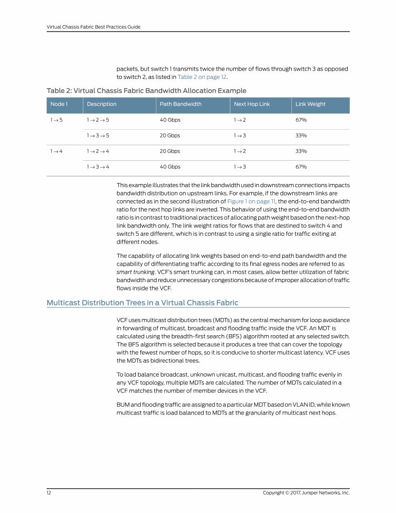
packets, but switch 1 transmits twice the number of flows through switch 3 as opposed
to switch 2, as listed in Table 2 on page 12.
Table 2: Virtual Chassis Fabric Bandwidth Allocation Example
LinkWeightNext Hop LinkPath BandwidthDescriptionNode 1
67%1 → 240 Gbps1 → 2 → 51 → 5
33%1 → 320 Gbps1 → 3 → 5
33%1 → 220 Gbps1 → 2 → 41 → 4
67%1 → 340 Gbps1 → 3 → 4
This example illustrates that the link bandwidth used in downstream connections impacts
bandwidth distribution on upstream links. For example, if the downstream links are
connected as in the second illustration of Figure 1 on page 11, the end-to-end bandwidth
ratio for the next hop links are inverted. This behavior of using the end-to-end bandwidth
ratio is in contrast to traditional practices of allocating path weight based on the next-hop
link bandwidth only. The link weight ratios for flows that are destined to switch 4 and
switch 5 are different, which is in contrast to using a single ratio for traffic exiting at
different nodes.
The capability of allocating link weights based on end-to-end path bandwidth and the
capability of differentiating traffic according to its final egress nodes are referred to as
smart trunking. VCF’s smart trunking can, in most cases, allow better utilization of fabric
bandwidth and reduce unnecessary congestions because of improper allocation of traffic
flows inside the VCF.
Multicast Distribution Trees in a Virtual Chassis Fabric
VCF uses multicast distribution trees (MDTs) as the central mechanism for loop avoidance
in forwarding of multicast, broadcast and flooding traffic inside the VCF. An MDT is
calculated using the breadth-first search (BFS) algorithm rooted at any selected switch.
The BFS algorithm is selected because it produces a tree that can cover the topology
with the fewest number of hops, so it is conducive to shorter multicast latency. VCF uses
the MDTs as bidirectional trees.
To load balance broadcast, unknown unicast, multicast, and flooding traffic evenly in
any VCF topology, multiple MDTs are calculated. The number of MDTs calculated in a
VCF matches the number of member devices in the VCF.
BUM and flooding traffic are assigned to a particular MDT based on VLAN ID, while known
multicast traffic is load balanced to MDTs at the granularity of multicast next hops.
Copyright © 2017, Juniper Networks, Inc.12
Virtual Chassis Fabric Best Practices Guide
Control Path Resiliency and High Availability in a Virtual Chassis Fabric
This section discusses control path resiliency and high availability in a VCF, and includes
the following sections:
• Control Path Resiliency on page 13
• Graceful Routing Engine Switchover (GRES) on page 13
• Nonstop Software Upgrade (NSSU) on page 13
Control Path Resiliency
VCF utilizes an in-band virtual backplane to carry fabric control traffic. The control plane
software utilizes the built-in path resiliency to achieve control plane resiliency. VCF
topologies can add multiple paths between any two nodes in the fabric by adding spine
devices; for instance, a path from leaf node 1 to leaf node 2 has two paths when a VCF
is using two spine devices, and four paths when a VCF is using four spines. VCF topologies
should be created with the understanding that adding spine devices improves performance
by providing multiple paths for traffic to travel and resiliency because additional paths
remain available when a spine device fails.
NOTE: You should not configuremore than64VCPsona single spinedevice.
Graceful Routing Engine Switchover (GRES)
VCF is a dual Routing Engine architecture that supports graceful Routing Engine switchover
(GRES). GRES allows the backup Routing Engine to assume the master Routing Engine
role without interruption to packet forwarding if the master Routing Engine fails.
GRES preserves interface and kernel information so that traffic is not interrupted during
a switchover. GRES alone, however, does not preserve the control plane in the event of
a master Routing Engine failure. Other events, such as protocol timers expiring or neighbor
relationships dropping, can happen during a routing engine switchover. These behaviors
are mitigated using nonstop active outing (NSR) and nonstop bridging (NSB), which are
supported for VCF.
See Configuring Graceful Routing Engine Switchover for additional information on GRES
in a VCF.
Nonstop Software Upgrade (NSSU)
Nonstop software upgrade (NSSU) provides a mechanism for upgrading Junos OS on
Juniper Networks EX and QFX Series Ethernet Switches in a VCF using a single
command-line interface (CLI) command with minimal traffic disruption. For VCFs that
support NSSU, the feature requires active redundant Routing Engines to successfully
upgrade the VCF, and the VCF must be preprovisioned.
NSSU leverages the underlying high availability features such as GRES, NSR, and NSB
to enable upgrading the Junos OS version running on a switch or in a VCF configuration
13Copyright © 2017, Juniper Networks, Inc.
Chapter 2: Understanding Virtual Chassis Fabric
with no disruption to the control plane and minor, sub-second interruption to the data
plane. NSSU upgrades member switches individually, permitting traffic to continue to
flow through the line card switches that are not being upgraded. By configuring link
aggregation groups (LAGs) such that the member links reside on different member
switches, it is possible to achieve little to no sub-second traffic disruption on your VCF
when performing an NSSU.
See Understanding Nonstop Software Upgrade on a Virtual Chassis Fabric for additional
information on NSSU in a VCF.
Copyright © 2017, Juniper Networks, Inc.14
Virtual Chassis Fabric Best Practices Guide
CHAPTER 3
Virtual Chassis Fabric Design andConfiguration
• VCF Objective Metrics on page 15
• Reference Virtual Chassis Fabric Topologies on page 16
• Mixed Virtual Chassis Fabric on page 17
• Fabric Mode on page 18
• Virtual Chassis Fabric License Requirement on page 19
• Virtual Chassis Fabric Provisioning on page 19
• VCF Configuration Steps on page 23
VCFObjective Metrics
This section provides information on the following objective metrics that you should
consider when configuring a VCF:
• Latency on page 15
• Fabric Link Resiliency on page 16
• Fabric Bandwidth on page 16
Latency
VCF has a deterministic latency for both unicast and multicast traffic.
For unicast traffic forwarding, VCF utilizes the Djikstra shortest path first (SPF) algorithm.
The overall latency is determined by the number of hops on the shortest paths from the
ingress node to the egress node.
Multicast latency is determined by:
• The multicast distribution tree (MDT) that is selected to forward a multicast packet.
MDT selection is based on the multicast group’s next hop.
• The distance—the number of hops—from the ingress node on the MDT to the egress
node on the MDT.
15Copyright © 2017, Juniper Networks, Inc.
Fabric Link Resiliency
When designing a VCF topology, you should ensure fabric link resiliency between any
pair of nodes within the VCF to avoid cases of link and node failures. Fabric link resiliency
is improved in a VCF by adding spine devices that are interconnected to all satellite
devices in the VCF. A leaf device in a VCF that has four spine devices, for instance, has
four paths to every other leaf device in the VCF.
You must configure at least two spine devices in all VCF topologies. A two spine device
topology ensures some fabric resiliency as well as support for NSSU. In most VCF
topologies, however, you should configure four spine devices if possible to provide
maximum fabric link resiliency.
You do not want a VCF to split in the event of a failed link or member switch. A good
design principle for fabric link resiliency is to ensure that, under any single link or switch
failure, the VCF topology remains fully connected.
Fabric Bandwidth
When designing a VCF, know the total bandwidth of a particular VCF path and determine
whether the topology design satisfies your traffic needs.
• Unicast bandwidth—The maximum fabric bandwidth for unicast traffic between any
pair of two nodes is the sum of the smallest segment bandwidth on all end-to-end
paths. Therefore, unicast bandwidth between any node pair can be increased by adding
intermediate devices in between. In a spine and leaf topology, bandwidth between
leaf devices can be increased by adding spine devices.
• Multicast bandwidth—Multicast traffic travels along a multicast distribution tree on
the VCF topology. An MDT is composed of hop-by-hop link segments. Therefore, a
VCF’s fabric multicast bandwidth is the minimum bandwidth of all aggregated fabric
links between directly connected neighbors.
Reference Virtual Chassis Fabric Topologies
This section provides three VCF reference topologies, and a summary of the pros and
cons of each topology.
NOTE: A VCF should include at least four members—two spine devices andat least two leaf devices. A three-member VCF is not a supportedconfiguration. For topologies with three or fewer members, use a VirtualChassis configuration instead.
Figure 2 on page 17 shows the reference topologies.
Copyright © 2017, Juniper Networks, Inc.16
Virtual Chassis Fabric Best Practices Guide

Figure 2: Good and Bad Spine and Leaf Examples
Example 1: If you want to build a VCF with two spine devices, we recommended that you
use all 40-Gbps links, as shown in the first topology in Figure 2 on page 17. In this topology,
the multicast bandwidth for the VCF is 40 Gbps.
Example 2: If you want to build a VCF with 40-Gbps and 10-Gbps links between spine
and leaf devices, we recommend that all 40-Gbps links are terminated on the same set
of spine devices, and all 10-Gbps fabric links are also terminated on the same set of
spines, as shown in the second topology in Figure 2 on page 17. Note that in this scenario,
bandwidth for leaf-to-leaf unicast traffic is 50 Gbps while the fabric bandwidth for
multicast traffic is only 10 Gbps.
Example 3: We do not recommended mixing path bandwidth at a single spine, as show
in the third topology in Figure 2 on page 17. VCF still functions in these topologies, but
performance is not optimal. These topologies should only be used as transient topologies
and are not recommended for production networks.
Mixed Virtual Chassis Fabric
A VCF with member switches from more than one product family is called a mixed VCF.
The following product families can be combined into a mixed QFX5100 VCF, which is a
VCF where the spine devices are QFX5100 switches, and the leaf devices can be any of
the following:
• QFX5100 switches
• QFX3500 and QFX3600 switches
• EX4300 switches
NOTE: AQFX5110 VCF, which is a VCFwhere the spine devices areQFX5110-32Q switches, can contain all QFX5110 switches or amixture ofQFX5110 and QFX5100 switches as leaf members. In either case, a QFX5110VCF is considered to be a non-mixed VCF because both switch types run thesame software imagewhen interconnected into a QFX5110 VCF, and you arenot required to set mixedmode. A QFX5110 VCF cannot include QFX3500,QFX3600, or QFX4300 switches.
The key benefits of allowing a mixed QFX5100 VCF include:
• Diversification of supported interfaces as the devices broaden the mix of 1-Gbps,
10-Gbps, and 40-Gbps network ports available in the VCF.
17Copyright © 2017, Juniper Networks, Inc.
Chapter 3: Virtual Chassis Fabric Design and Configuration

• Increased investment protection as previously purchased switches can be included in
the VCF.
A QFX5100 VCF must use QFX5100 switches as spine devices, so a non-mixed QFX5100
VCF uses all QFX5100 switches as spine and leaf devices. A mixed QFX5100 VCF is any
VCF that has at least one QFX3500, QFX3600, or EX4300 switch among the leaf devices.
The optimal QFX5100 VCF topology is to use a non-mixed VCF with QFX5100 switches
only. A VCF composed entirely of QFX5100 switches supports the largest breadth of
features available at the highest scalability and with the most high-speed interfaces as
compared to QFX3500, QFX3600, and EX4300 switches. However, a mixed QFX5100
VCF gives you the flexibility to employ existing devices from your network as leaf devices.
NOTE:
The optimal VCF topology among all devices that support VCF technologyis a QFX5110 VCFwith all QFX5110 switches. A VCF composed entirely ofQFX5110 switches supports the largest breadth of features available atmaximum scalability with the highest speed interfaces. However, you alsohave the flexibility to employ existing QFX5100 switches from your networkas leaf devices in a QFX5110 VCF.
All member switches in a mixed QFX5100 VCF must be configured into mixed mode using
the request virtual-chassis modemixed command. A device reboot is required for an
update to the mixed mode setting to take effect. Mixed mode configuration is not required
for a QFX5110 VCF that contains both QFX5110 and QFX5100 switches.
For more information on a mixed VCF, including the switches that can fulfill each role in
a VCF, seeUnderstandingMixed EX Series andQFXSeries Virtual Chassis or Virtual Chassis
Fabric.
Fabric Mode
A switch must be configured into fabric mode for it to properly join a VCF. You should
configure a device into fabric mode before interconnecting it into a VCF.
NOTE: In autoprovisioned configurations, if a device is interconnected intoa VCF before having fabric mode configured, the VCFwill automatically setfabric mode and reboot the device. However, having a device rebootautomatically during VCF configuration and operation can be unexpected.As a result, in this case you also usually want to configure fabric mode (andmixedmodeat the same time, if applicable), and reboot thedevicemanuallybefore adding it to theVCF, rather than having theVCFdo this automatically.
To change the fabric mode of a switch, enter the following command:
user@switch>requestvirtual-chassismodefabric[local |membermember-number |all-members][reboot]
Copyright © 2017, Juniper Networks, Inc.18
Virtual Chassis Fabric Best Practices Guide
A reboot is required for a fabric mode change to take effect on the switch. If you are
creating a mixed VCF, you have to configure all switches in the VCF into mixed Virtual
Chassis mode. Because a reboot is also required to change the Virtual Chassis mode, we
recommend changing the Virtual Chassis mode at the same time as you change the
fabric mode so that you can update and apply both settings with a single reboot.
When fabric mode is disabled, switches can form a Virtual Chassis but cannot form a
VCF because the enhanced fabric capabilities are not available.
SeeUnderstandingVirtual Chassis Fabric Components for additional information on fabric
mode, andUnderstandingMixed EXSeries andQFXSeries Virtual Chassis or Virtual Chassis
Fabric for details on which combinations of switches in a VCF require you to set
mixed-mode.
Virtual Chassis Fabric License Requirement
A feature license is required to configure a VCF.
The VCF feature license is an independent feature license. The VCF feature license is not
included in the enhanced feature licenses (EFLs) or the advanced feature licenses (AFLs)
that are purchased to enable some features on some Juniper Networks switches.
For a VCF deployment, we recommend two license keys for redundancy—one for the
device in the master Routing Engine role and the other for the device in the backup Routing
Engine role.
Virtual Chassis Fabric Provisioning
This section discusses VCF provisioning and covers the following topics:
• Virtual Chassis Fabric Provisioning Overview on page 19
• Default Port Types on page 20
• Preprovisioned on page 21
• Autoprovisioned on page 22
• Nonprovisioned (Default. Not recommended) on page 22
Virtual Chassis Fabric Provisioning Overview
There are two methods to configure a VCF using the Junos CLI:
• Preprovisioning—In a preprovisioned configuration, you deterministically control the
devices in your VCF by associating each device’s serial number to a member ID and
role.
In a preprovisioned VCF, you must add a switch to the preprovisioned configuration
before it is recognized by the VCF. Switches that are not included in the preprovisioned
configuration cannot join the VCF.
The advantage of configuring a VCF using a preprovisioned configuration is that you
can explicitly control which devices are added to your VCF, and in what roles.
19Copyright © 2017, Juniper Networks, Inc.
Chapter 3: Virtual Chassis Fabric Design and Configuration
• Autoprovisioning—In an autoprovisioned configuration, you deterministically control
the spine device configuration in your VCF by associating each spine device’s serial
number to a member ID and role. After the spine device configuration is established,
you can cable leaf devices into the VCF without updating the VCF configuration. Leaf
evices that have been zeroized or have the factory default configuration automatically
join the VCF when they are interconnected with a spine device—the connecting ports
are converted to VCPs, the VCF detects and sets fabric mode or mixed mode if
necessary, and automatically reboots the device if either mode is updated.
The advantage of autoprovisioned configuration is convenience because you can “plug
and play” leaf devices into a VCF after minimal initial configuration.
NOTE: In some scenarios, unexpectedbehaviormight occurwhenamixedmode VCF is autoprovisioned. If you are having trouble autoprovisioning amixedmode VCF, use preprovisioning for the VCF instead ofautoprovisioning.
A VCF can also be nonprovisioned. We discourage nonprovisioned VCF configuration.
You can configure all aspects of a VCF using autoprovisioned or preprovisioned
configuration. A nonprovisioned VCF configuration should only be used by VCF experts
in specialized scenarios.
A nonprovisioned VCF is the default method for creating a VCF; it is the configuration
mode used when a VCF has not been configured into autoprovisioned or preprovisioned
mode.
Default Port Types
Ports on any member switch in a VCF that are used to connect to external nodes are
called network ports. Ports that are connecting member switches together in a VCF are
called Virtual Chassis ports (VCPs). For neighboring member switches to interconnect
and form a VCF, the interconnecting links must be VCPs or be converted into VCPs.
Juniper Networks switches have the following port types:
• Dedicated VCPs—A port that can only be used as a VCP port. EX4200 and EX4550
switches have dedicated VCPs.
Dedicated VCPs are not used in a VCF, as no switches that can be installed in a VCF
support dedicated VCPs.
• Dedicated network ports—A port that can only be used as a network port. Most 1-Gbps
Ethernet interfaces on Juniper Networks switches are dedicated network ports.
• Convertible ports—These ports can function as VCPs or network ports. Most 10-Gbps
SFP+ and 40-Gbps QSFP+ interfaces on Juniper Networks switches that support
Virtual Chassis and Virtual Chassis Fabric technology are convertible ports. Some
switches have 40-Gbps and 100-Gbps QSFP28 port options. Although the 100-Gbps
ports are usually used as uplink ports to take advantage of the higher speed, they can
be converted into VCPs as well. 40-Gbps and 100-Gbps ports that are channelized
into lower-speed options cannot be used as VCPs.
Copyright © 2017, Juniper Networks, Inc.20
Virtual Chassis Fabric Best Practices Guide

NOTE: In preprovisioned or autoprovisioned VCFs, the Automatic VCPconversion (AVC) capability is enabled. The AVC function utilizes the LinkLayerDiscoveryProtocol (LLDP) to identify links that need tobe convertedinto VCPs when a device is interconnected into a VCF, so LLDP—which isenabled on all interfaces on EX Series and QFX Series switches, bydefault—must be enabled to use AVC.
• Default VCPs—Convertible ports that are configured into VCPs by default. The 40-Gbps
QSFP+ interfaces on EX4300 switches are default VCPs.
Table 3 on page 21 summarizes the port types available for all switches that can be
included in a VCF.
Table 3: Port Types
Default VCPsConvertible PortsDedicated VCPsSwitch
40-Gbps QSFP+interfaces
Most 10-Gbps SFP+ and 40-Gbps QSFP+ interfaces.
For specific interface support, see Pluggable TranceiversSupported on EX Series Switches.
Not supportedEX4300
No default VCPs10-Gbps SFP+ and 40-Gbps QSFP+ interfaces.
For specific interface support, seeConnectingaQFX3500or QFX3600 Switch in a Virtual Chassis Fabric.
Not supportedQFX3500
No default VCPs10-Gbps SFP+ and 40-Gbps QSFP+ interfaces.
For specific interface support, seeConnectingaQFX3500or QFX3600 Switch in a Virtual Chassis Fabric.
Not supportedQFX3600
No default VCPs10-Gbps SFP+ and 40-Gbps QSFP+ interfaces.
See Connecting a QFX5100 Device in a Virtual ChassisFabric.
Not supportedQFX5100
No default VCPs10-Gbps SFP+, 40-Gbps QSFP+, and 40-Gbps or 100-GbpsQSFP28 interfaces.
See Connecting a QFX5110 Device in a Virtual ChassisFabric.
Not supportedQFX5110
(These have flexibleport configurationoptions.)
Preprovisioned
Preprovisioned configuration mode is enabled using the following command:
[edit virtual-chassis]user@device# set preprovisioned
21Copyright © 2017, Juniper Networks, Inc.
Chapter 3: Virtual Chassis Fabric Design and Configuration

Automatic VCP conversion is supported in preprovisioned or autoprovisioned VCFs, which
uses the LLDP protocol with Juniper’s vendor-specific TLVs to identify links that need to
be converted into VCPs.
LLDP is enabled on all interfaces on EX Series and QFX Series switches by default, but
if needed, to enable LLDP on all interfaces on an EX or QFX Series switch:
[edit]user@device# set protocols lldp interface all
The VCCP daemon (VCCPd) uses LLDP messages to exchange messages on all network
ports that are convertible to VCP ports.
The sending and receiving switches use these LLDP messages to determine if the ports
belong to the same VCF. If the switches belong to the same VCF, the AVC procedure
converts the ports connecting the switches into VCPs.
Detailed step-by-step preprovisioning instructions are available atPreprovisioningaVirtual
Chassis Fabric.
Autoprovisioned
Autoprovisioned mode is enabled by the following configuration:
[edit virtual-chassis]user@device# set auto-provisioned
As previously mentioned, automatic VCP conversion is supported in preprovisioned or
autoprovisioned VCFs, which uses the LLDP protocol with Juniper’s vendor-specific TLVs
to identify links that need to be converted into VCPs.
LLDP is enabled on all interfaces on EX Series and QFX Series switches by default, but
if needed, to enable LLDP on all interfaces on an EX or QFX Series switch:
[edit]user@device# set protocols lldp interface all
Detailed step-by-step autoprovisioning instructions are available at Autoprovisioning a
Virtual Chassis Fabric.
Nonprovisioned (Default. Not recommended)
CAUTION: ConfigureyourVirtualChassisFabric (VCF)usingautoprovisioningor preprovisioning unless you have a compelling reason to use anonprovisioned configuration. You can configure all aspects of a VCF usingan autoprovisioned or preprovisioned configuration. The process forautoprovisioning your VCF is described in Autoprovisioning a Virtual Chassis
Fabric and the process for preprovisioning your VCF is described in
Preprovisioning a Virtual Chassis Fabric.
A nonprovisioned VCF configuration is highly discouraged and should onlybe used by VCF experts in specialized scenarios.
Copyright © 2017, Juniper Networks, Inc.22
Virtual Chassis Fabric Best Practices Guide
http://www.juniper.net/documentation/en_US/junos/topics/task/configuration/vcf-autoprovisioning.html
http://www.juniper.net/documentation/en_US/junos/topics/task/configuration/vcf-autoprovisioning.html
http://www.juniper.net/documentation/en_US/junos/topics/task/configuration/vcf-autoprovisioning.html

The VCF operates in its default mode, nonprovisioned mode, when autoprovisioning or
preprovisioning is not used.
In nonprovisioned mode, you manually convert any convertible network port into a VCP
to form a VCF. Use the following commands to convert an interface into a VCP:
To convert a network port on a member switch into a VCP port:
user@device>request virtual-chassis vc-port set pic-slot pic-slot-number port port-number
To convert a VCP port on a member switch into a network port:
user@device>request virtual-chassis vc-port delete pic-slot pic-slot-number port port-number
For detailed step-by-step instructions for configuring a nonprovisioned VCF, see
Configuring a Nonprovisioned Virtual Chassis Fabric.
VCF Configuration Steps
This section provides a high-level overview of the VCF configuration steps and includes
the following sections:
• Virtual Chassis Fabric Preparation Review on page 23
• Selecting a Provisioning Method on page 25
• Autoprovisioning a VCF on page 25
• Preprovisioning a VCF on page 29
• Nonprovisioning a VCF on page 31
• Adding a Leaf Device to an Operational VCF on page 32
Virtual Chassis Fabric Preparation Review
Before starting to configure the VCF, the following design decisions should be made
based on information in prior sections of this document:
1. Topology. Determine which spine and leaf architecture is the right topology for your
network.
2. Type of devices in your VCF.
• A QFX5110 VCF is a VCF with QFX5110 spine devices and any combination of
supported QFX5100 and QFX5110 leaf devices. Both types of devices run the same
Junos OS software image when interconnected together and configured into a
QFX5110 VCF, so this is considered to be a non-mixed VCF. For best results when
planning a QFX5100 VCF, use only QFX5110-32Q switches as the spine devices.
• A QFX5100 VCF is a VCF with QFX5100 spine devices, and can have only QFX5100
leaf devices (a non-mixed QFX5100 VCF) or a combination of QFX5100, QFX3500,
QFX3600, and EX4300 leaf devices running compatible Junos OS software (a
mixed QFX5100 VCF).
See Virtual Chassis Fabric Overview for details on the topology and devices that can
be in a VCF.
23Copyright © 2017, Juniper Networks, Inc.
Chapter 3: Virtual Chassis Fabric Design and Configuration

3. Mixed or non-mixed VCF. Determine whether your VCF is a non-mixed VCF (see the
previous step and Understanding Mixed EX Series and QFX Series Virtual Chassis or
Virtual Chassis Fabric).
The optimal QFX5110 VCF topology is to use all QFX5110 devices, and specifically
QFX5110-32Q switches as the spine devices. A QFX5110 VCF composed entirely of
QFX5110 devices supports the largest breadth of features at the highest scalability
while also supporting the highest number of high-speed interfaces.
The optimal QFX5100 VCF topology is to use a non-mixed VCF with QFX5100 devices
only. A QFX5100 VCF composed entirely of QFX5100 devices supports the largest
breadth of features at the highest scalability while also supporting the highest number
of high-speed interfaces available on QFX5100 switches.
These decisions should be made before performing the VCF configuration steps for the
following reasons:
• You need to know the topology to cable and configure the switches.
• A QFX5110 VCF can only be set up using QFX5110 and QFX5100 switches that are
running the same Junos OS software, which must be a software image that includes
“-qfx-5e-” in the software package filename when the Junos OS package is downloaded
from the Software Center. QFX5100 switches running a Junos OS image that includes
“-qfx-5-” in the software package filename must be upgraded to a package filename
that includes “-qfx-5e-” before being included in a QFX5110 VCF. The upgrade requires
rebooting the QFX5100 switch from USB install media and rebooting the switch. See
UpgradingaQFX5100SwitchwithaUSBDevice to JoinaQFX5110VirtualChassisorVirtual
Chassis Fabric for details.
• All member switches in a mixed VCF have to be rebooted to change the VCF mode. In
a mixed-mode VCF, we recommend changing the fabric and mixed mode on each
member switch—changing the fabric mode is a mandatory step that always requires
a reboot—at the same time so that you can reboot the switch once for both
configuration changes to take effect.
Most other design and configuration decisions, such as adding or removing VCPs, adding
or removing member switches, or switching between preprovisioned and autoprovisioned
configuration processes, can usually be changed without requiring system downtime.
Once a VCF topology has been decided, the VCF configuration generally involves the
following steps:
1. Select either the preprovisioned or the autoprovisioned method of configuring the
VCF.
2. Prepare each member switch for the VCF, including upgrading the member switches
to the appropriate version of Junos OS that supports VCF, and setting the member
switches into fabric mode and, if applicable, mixed mode.
Copyright © 2017, Juniper Networks, Inc.24
Virtual Chassis Fabric Best Practices Guide

3. Create the appropriate Virtual Chassis configuration.
4. Connect the VCPs.
Selecting a ProvisioningMethod
You can provision a VCF in one of the following ways:
• Autoprovision
• Preprovision
• Nonprovision (not recommended)
Consider the following factors when selecting a provisioning method:
• Autoprovisioning: Autoprovisioning simplifies the configuration process, because you
can plug and play leaf devices into the VCF after completing a minimal initial
configuration procedure that includes specifying the spine devices.
• Preprovisioning: Preprovisioning allows you to explicitly control the composition of the
VCF, but it is more labor-intensive than autoprovisioning because you have to collect
and configure the serial number of each member switch in the VCF.
• Nonprovisioning: We discourage the use of nonprovisioned VCF configuration. Only
use a nonprovisioned VCF configuration if you are an expert user and you have a clear
understanding of why you are using a nonprovisioned configuration over an
autoprovisioned or a preprovisioned configuration.
Autoprovisioning a VCF
To autoprovision a VCF, you must first configure the roles and serial numbers of the spine
switches before the leaf devices can plug and play into the VCF.
For detailed step-by-step instructions for configuring your VCF using autoprovisioning,
see Autoprovisioning a Virtual Chassis Fabric.
This section discusses the following topics:
• Preparing a Leaf Device on page 25
• Sample VCF Autoprovisioned Configuration on page 27
• Connecting the VCPs on page 27
• Understanding VCP Link Aggregation Group Creation on page 29
• Stopping Automatic VCP Conversion on page 29
Preparing a Leaf Device
In an autoprovisioned VCF, you can plug-and-play leaf devices into the VCF. In an
autoprovisioned VCF, VCPs are created automatically as leaf devices are cabled to spines
devices.
25Copyright © 2017, Juniper Networks, Inc.
Chapter 3: Virtual Chassis Fabric Design and Configuration
Routing Engine Preparation
When building a mixed VCF, follow these rules:
• Select your Routing Engines from the list of eligible Routing Engine switch models. See
Understanding Mixed EX Series and QFX Series Virtual Chassis or Virtual Chassis Fabric.
• Configure and install your Routing Engine switches before your line card switches.
While you are not required to install the Routing Engine switches first, master and
backup synchronizations occur as part of the Routing Engine switch process and
multiple switchovers can lead to unpredictable results.
• (Recommended) Zeroize your spine device.
All spine switches must be provisioned and are not required to be in factory-default
state. However, an automatic reboot procedure is performed when the spine switch
is not in the factory default state. If a switch was previously deployed in a Virtual Chassis
or VCF, we recommend using the requestsystemzeroize to erase all VCP configurations
and to allow the automatic VCP conversions to happen without interference.
• Ensure that LLDP is enabled on all switches that will become VCPs.
LLDP is enabled by default on all EX and QFX Series switch interfaces, so you only
need to perform this check if the LLDP configuration was previously modified. See
Configuring LLDP (CLI Procedure).
• Ensure the spine switches are set into the right mode before building the VCF. In the
following example, a master Routing Engine switch in a mixed VCF is set into mixed
fabric mode before building the VCF:
user@switch> request virtual-chassis mode fabric mixed local [reboot]Mode set to 'Fabric with mixed devices'. (Reboot required)
After the switch is rebooted, it will be set to operate in mixed fabric mode.
Leaf Device Preparation
Leaf devices must meet the following requirements before being interconnected into a
VCF to be able to plug and play:
• The switch must be in factory default mode.
A switch received from the factory that has not been configured can be immediately
installed into an autoprovisioned VCF as a leaf device.
For switches that have previously been used in a network, set the switch into factory
default mode by entering the request system zeroize command:
user@switch> request system zeroize
• (EX4300 switches using 40-Gbps interfaces only) Delete the existing VCP
configurations.
The 40-Gbps QSFP+ interfaces on EX4300 switches are configured as VCPs, by default.
Automatic VCP conversion only works when the interfaces on both ends of the link are
Copyright © 2017, Juniper Networks, Inc.26
Virtual Chassis Fabric Best Practices Guide

not configured into VCPs. You must, therefore, delete the default VCP configuration
on 40-Gbps QSFP+ interfaces on the EX4300 switches for AVC to work. You can delete
a VCP configuration using the request virtual-chassis vc-port delete command.
Sample VCF Autoprovisioned Configuration
This section shows a sample autoprovisioned VCF configuration.
You should configure the VCF from the master Routing Engine:
Switch-1>show configurations virtual-chassisauto-provisioned;member 0 {role routing-engine;serial-number BBAK8864;
}member 1 {role routing-engine;serial-number ED3702;
}member 2 {role line-card;serial-number BBAK8714;
}member 3 {role line-card;serial-number BBAK8759;
}{master:0}Switch-1>
This configuration only includes the serial numbers of the spine devices. You must
configure two spine devices into the Routing Engine role and, if you are using three or
four spine devices, configure the non-Routing Engine spine devices into the linecard role.
Connecting the VCPs
With any autoprovisioned configuration, including the sample configuration in the previous
section, VCPs form automatically as leaf devices are cabled to the spine device.
The following actions might occur to newly-cabled leaf devices after the VCPs are formed:
• the leaf device might reboot.
• ports are automatically converted into VCPs.
• the leaf device joins the VCF.
• the spine device joins the VCF.
Each of these actions is discussed in more detail in the following sections.
Understanding the Leaf Device Reboot
Leaf devices automatically reboot when cabled to spine devices in an autoprovisioned
configuration when the fabric mode or mixed mode needs to be changed to match the
settings in the master spine device.
27Copyright © 2017, Juniper Networks, Inc.
Chapter 3: Virtual Chassis Fabric Design and Configuration
Because your leaf switch is zeroized before it is cabled into a VCF, expect your leaf device
to reboot immediately after you cable it into a VCF.
The leaf device is recognized by the VCF after the reboot.
Automatic VCP Conversion
Leaf devices automatically convert ports to VCPs in an autoprovisioned configuration.
For the automatic VCP conversion procedure to work, both ends of the link must be set
as network ports initially.
NOTE: The 40-Gbps QSFP+ interfaces on EX4300 switches are configuredas VCPs, by default. Automatic VCP conversion (AVC) only works when theinterfaces on both ends of the link are not configured into VCPs. Youmust,therefore,delete thedefaultVCPconfigurationon40-GbpsQSFP+ interfaceson theEX4300switches for AVC towork. You candelete aVCPconfigurationusing the request virtual-chassis vc-port delete command.
The process to create the VCP can take up to 60 seconds. If multiple same-speed links
are interconnected between the same spine and aggregation devices, the VCPs
automatically form a VCP LAG.
Leaf Devices Joining the VCF
After the network ports are converted into VCPs, the leaf switches are brought into the
VCF and assigned member ID numbers.
Spine Devices Joining the VCF
If you add a spine device to an autoprovisioned VCF, you must first update the
configuration to specify the new spine device’s serial number and assign it a member ID.
A spine device joining an existing VCF goes through various procedures similar to a leaf
switch joining a VCF, including:
• The spine switch reboots when the fabric mode or mixed mode is updated because it
is not consistent with the master Routing Engine.
NOTE: Werecommendchangingthefabricandmixedmodesettingsbeforeinterconnecting your newspinedevice into theVCFbyentering the requestvirtual-chassis mode fabric mixed local reboot command. This actionavoids apotentially unexpected automatic device reboot upon cabling thedevice into the VCF.
• The joining spine switch reboots if it is in the factory-default state.
• Network ports are automatically converted into VCPs.
Copyright © 2017, Juniper Networks, Inc.28
Virtual Chassis Fabric Best Practices Guide
Understanding VCP Link Aggregation Group Creation
After the autoprovisioned VCF is formed, parallel links—same speed links connecting the
same spine device to the same leaf device—between any pair of member switches are
automatically converted into a VCP LAG and the combined bandwidth is added to fabric
path calculations.
Stopping Automatic VCP Conversion
Once a VCF is formed, stopping the autoprovisioning process can avoid bringing in
additional chassis into the VCF by mistake, especially in cases where you want to use
the uplink interfaces on the spine devices as network ports.
To stop the autoprovisioning process, you can do one of the following two things:
• Disable LLDP on all the interfaces that are going to connect new member switches.
• Convert the autoprovisioned VCF into a preprovisioned VCF. This is a straightforward
process because all of the member switches have serial numbers that are already
discovered.
Preprovisioning a VCF
This topic describes the extra steps that are required to form a mixed VCF using
preprovisioning instead of autoprovisioning. For detailed step-by-step instructions for
configuring your VCF using autoprovisioning, see Preprovisioning a Virtual Chassis Fabric.
• Member Switch Preparation on page 29
• Preprovisioned VCF Configuration on page 31
• Connecting the VCPs on page 31
Member Switch Preparation
As in an autoprovisioned VCF, each member switch in a preprovisioned VCF must be set
to the correct fabric and mixed mode for it to properly join the VCF. Setting these modes
should be done on Routing Engine spine devices manually before cabling the VCF. When
adding other spine or leaf devices, you can set these modes manually before
interconnecting the new device into the VCF to avoid requiring the device to be rebooted
at that time. Otherwise, for new devices that have been zeroized or are in the factory
default configuration, upon interconnecting the new device into the VCF, the automatic
VCP conversion process will also detect and set fabric and mixed modes if needed, and
automatically reboot the device.
Fabric and mixed modes can be enabled or disabled at the same time by using the
following operational commands on the member switch that is going to be a member
of the VCF:
user@switch> request virtual-chassis mode fabric mixed localMode set to 'Fabric with mixed devices'. (Reboot required)
29Copyright © 2017, Juniper Networks, Inc.
Chapter 3: Virtual Chassis Fabric Design and Configuration

BEST PRACTICE: TominimizedisruptiontoanexistingVCF,changethefabricandmixedmode settings and reboot a newmember switch before cablingit into the VCF.
You can, however, change the fabric andmixedmode settings and rebootyour switch after cabling it into a VCF.
The current and future mode settings of the member switches can be displayed by issuing
the following command:
user@switch> show virtual-chassis mode
fpc0:----------------------------------------------------------------------Current mode : Fabric with similar devices
Future mode after reboot : Fabric with mixed devices
fpc1:----------------------------------------------------------------------Current mode : Fabric with mixed devices
Future mode after reboot : Fabric with mixed devices
OPS>
Verify that current and future modes of all member switches are correct. If any member
switch’s current and future modes are different, a reboot is required for that switch. For
example, the previous display output shows that, in order for fpc0 and fpc1 to have the
same fabric mode and mixed mode, fpc0 needs to be rebooted to set its mode to mixed
mode.
Routing Engine Switch Preparation
The intended master Routing Engine switch is prepared in the same way as it is for an
autoprovisioned VCF.
Linecard Member Switch Preparation
Linecard member switches are prepared for a preprovisioned VCF in the same way as
spine member switches are prepared for an autoprovisioned VCF.
Note that because every member switch needs to be provisioned, the member switches
are not required to be in factory default state, as long as the intended linecards have
LLDP enabled on any potential VCP links. However, we still recommend that you zeroize
a linecard member switch before adding it to a VCF.
In addition to bringing a switch to its factory default configuration, the request system
zeroizecommand also removes all VCPs configured on the switch. If a switch is previously
used as member in a Virtual Chassis or VCF, the request system zeroize command can
be used to clean up previously converted VCP ports. This is required for the automatic
VCP port conversion procedure to be performed.
Copyright © 2017, Juniper Networks, Inc.30
Virtual Chassis Fabric Best Practices Guide

Preprovisioned VCF Configuration
In a preprovisioned VCF, all member switches are included in the Virtual Chassis
configuration on the intended master Routing Engine switch:
Switch-1> show configurations virtual-chassispreprovisioned;member 0 {role routing-engine;serial-number BBAK8864;
}member 1 {role routing-engine;serial-number ED3702;
}member 2 {role line-card;serial-number BBAK8714;
}member 3 {role line-card;serial-number BBAK8759;
}… // other members are omitted here …{master:0}Switch-1>
Connecting the VCPs
With the previously described preparations and configurations, the VCF will be formed
as VCP links are connected.
The actions taken by the member switches automatically during VCF formation are
similar to the actions in the autoprovisioned method until the VCF is fully formed.
These similar actions include:
• Provisioned member switches might reboot if they are in the factory-default state.
• Provisioned member switches reboot if the fabric or mixed mode needs to be changed.
• Automatic VCP port conversions occur.
Switches can only join the VCF if they are explicitly provisioned in the configuration.
Hence, there is no need to disable LLDP on any ports to stop automatically converting
VCPs. Instead, additional fabric links can be added between provisioned members and
they will be automatically converted to VCP links.
Nonprovisioning a VCF
CAUTION: ConfigureyourVirtualChassisFabric (VCF)usingautoprovisioningor preprovisioning unless you have a compelling reason to use a
31Copyright © 2017, Juniper Networks, Inc.
Chapter 3: Virtual Chassis Fabric Design and Configuration

nonprovisioned configuration. A nonprovisioned VCF configuration is highlydiscouraged.
Nonprovisioned VCF configuration should only be used by VCF experts inspecialized scenarios. You can configure all aspects of a VCF using anautoprovisioned or a preprovisioned configuration.
See Configuring a Nonprovisioned Virtual Chassis Fabric for instructions on configuring a
nonprovisioned VCF.
Adding a Leaf Device to an Operational VCF
When adding a leaf device to a VCF, be aware of the following factors:
• Make sure the new switch is running the same version of Junos OS that is running in
the VCF.
• Set the appropriate mode—either fabric or mixed fabric—and reboot the switch before
interconnecting it into the VCF.
• Zeroize the new device using the request system zeroize command.
• Update the VCF configuration to accommodate the new spine before cabling it into
the VCF.
Interconnect the new device to the spine member that is in the master Routing Engine
role first, which is the most efficient way to synchronize the new member with the current
VCF configuration and state. Interconnecting a new member only to the backup or another
spine member can cause flooding of messages within the VCF as the master tries to
synchronize the new member through other leaf and spine member VCP links. After the
new member is fully incorporated into the VCF, you can interconnect the remaining
redundant VCP links to the backup and other spine devices without affecting traffic within
the VCF.
See Adding a Device to a Virtual Chassis Fabric for detailed instructions on adding a leaf
device to a VCF.
Copyright © 2017, Juniper Networks, Inc.32
Virtual Chassis Fabric Best Practices Guide