Dediprog SF Software User Manual -...
12
D D e e d d i i P P r r o o g g T T e e c c h h n n o o l l o o g g y y C C o o . . L L t t d d w w w w w w . . d d e e d d i i p p r r o o g g . . c c o o m m 1 Dediprog SF Software User Manual V1.3 Last updated on February 2 nd 2007 Rorixwell Inc. Authorized distributor by Dediprog Technology Co., Ltd 10 Electro Road, Toronto, ON, M1R 2A7, Canada Tel: +1 (416) 757 0764 Fax: +1 (416) 757 0764 E-mail: [email protected] http://www.Rorixwell.com
Transcript of Dediprog SF Software User Manual -...

DDDeeedddiiiPPPrrroooggg TTTeeeccchhhnnnooolllooogggyyy CCCooo... LLLtttddd wwwwwwwww...dddeeedddiiippprrroooggg...cccooommm
1
Dediprog SF Software
User Manual
V1.3
Last updated on February 2nd
2007
Rorixwell Inc.Authorized distributor by Dediprog Technology Co., Ltd 10 Electro Road, Toronto, ON, M1R 2A7, Canada Tel: +1 (416) 757 0764Fax: +1 (416) 757 0764 E-mail: [email protected]
http://www.Rorixwell.com

DDDeeedddiiiPPPrrroooggg TTTeeeccchhhnnnooolllooogggyyy CCCooo... LLLtttddd wwwwwwwww...dddeeedddiiippprrroooggg...cccooommm
2
Table of content:
I. GENERAL INFORMATION .......................................................................3
A. Introduction .......................................................................................................... 3
II. Dediprog SF Software User Guide .................................................3
A. Environment Preparation...................................................................................... 3 1. Program the serial flash memory(chip 1) ......................................................................................3 2. Program the flash card ...................................................................................................................3
B. Program Application Memory ............................................................................. 3 1. Memory Detection.........................................................................................................................4 2. Tool Bar Explanation.....................................................................................................................4 3. Update Firmware ...........................................................................................................................6 4. Supported devices, Software version, Firmware version...............................................................7
C. Program the flash card.......................................................................................... 7 1. Operations to prepare the flash card ..............................................................................................7
D. Read Programming History.................................................................................. 9
III. Dediprog Windows DOS Command Line Software User Guide
10
A. Dediprog Windows DOS Command Line Support Display .............................. 10
B. How to Start ....................................................................................................... 10
C. Basic Usages: ..................................................................................................... 11
D. Usage Examples: ................................................................................................ 11
E. Basic Switches: .................................................................................................. 11
F. Optional Switches .............................................................................................. 11
Rorixwell Incorporation 10 Electro Road, Toronto, ON, Canada Tel: +1 (416) 7570764 Email: [email protected] Website: www.Rorixwell.com
DDDeeedddiiiPPPrrroooggg TTTeeeccchhhnnnooolllooogggyyy CCCooo... LLLtttddd wwwwwwwww...dddeeedddiiippprrroooggg...cccooommm
3
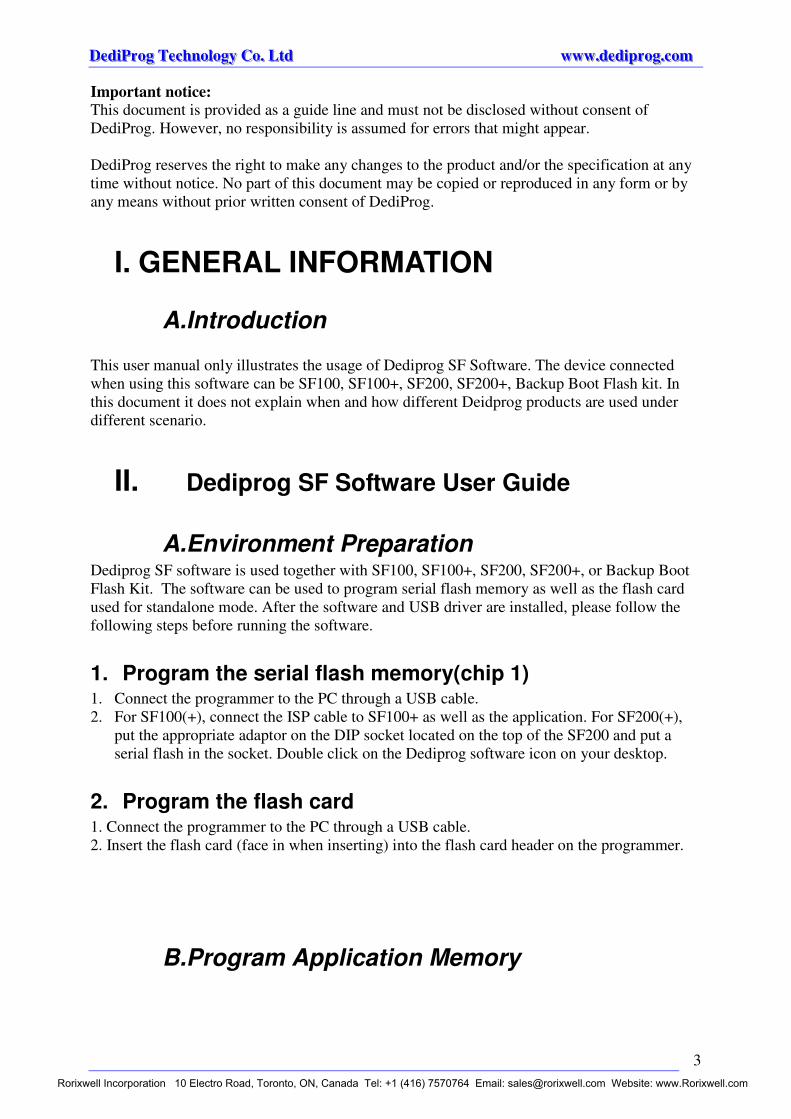
Important notice:
This document is provided as a guide line and must not be disclosed without consent of
DediProg. However, no responsibility is assumed for errors that might appear.
DediProg reserves the right to make any changes to the product and/or the specification at any
time without notice. No part of this document may be copied or reproduced in any form or by
any means without prior written consent of DediProg.
A.Introduction
This user manual only illustrates the usage of Dediprog SF Software. The device connected
when using this software can be SF100, SF100+, SF200, SF200+, Backup Boot Flash kit. In
this document it does not explain when and how different Deidprog products are used under
different scenario.
A.Environment Preparation Dediprog SF software is used together with SF100, SF100+, SF200, SF200+, or Backup Boot
Flash Kit. The software can be used to program serial flash memory as well as the flash card
used for standalone mode. After the software and USB driver are installed, please follow the
following steps before running the software.
1. Program the serial flash memory(chip 1) 1. Connect the programmer to the PC through a USB cable.
2. For SF100(+), connect the ISP cable to SF100+ as well as the application. For SF200(+),
put the appropriate adaptor on the DIP socket located on the top of the SF200 and put a
serial flash in the socket. Double click on the Dediprog software icon on your desktop.
2. Program the flash card 1. Connect the programmer to the PC through a USB cable.
2. Insert the flash card (face in when inserting) into the flash card header on the programmer.
B.Program Application Memory
I. GENERAL INFORMATION
II. Dediprog SF Software User Guide
Rorixwell Incorporation 10 Electro Road, Toronto, ON, Canada Tel: +1 (416) 7570764 Email: [email protected] Website: www.Rorixwell.com
DDDeeedddiiiPPPrrroooggg TTTeeeccchhhnnnooolllooogggyyy CCCooo... LLLtttddd wwwwwwwww...dddeeedddiiippprrroooggg...cccooommm
4
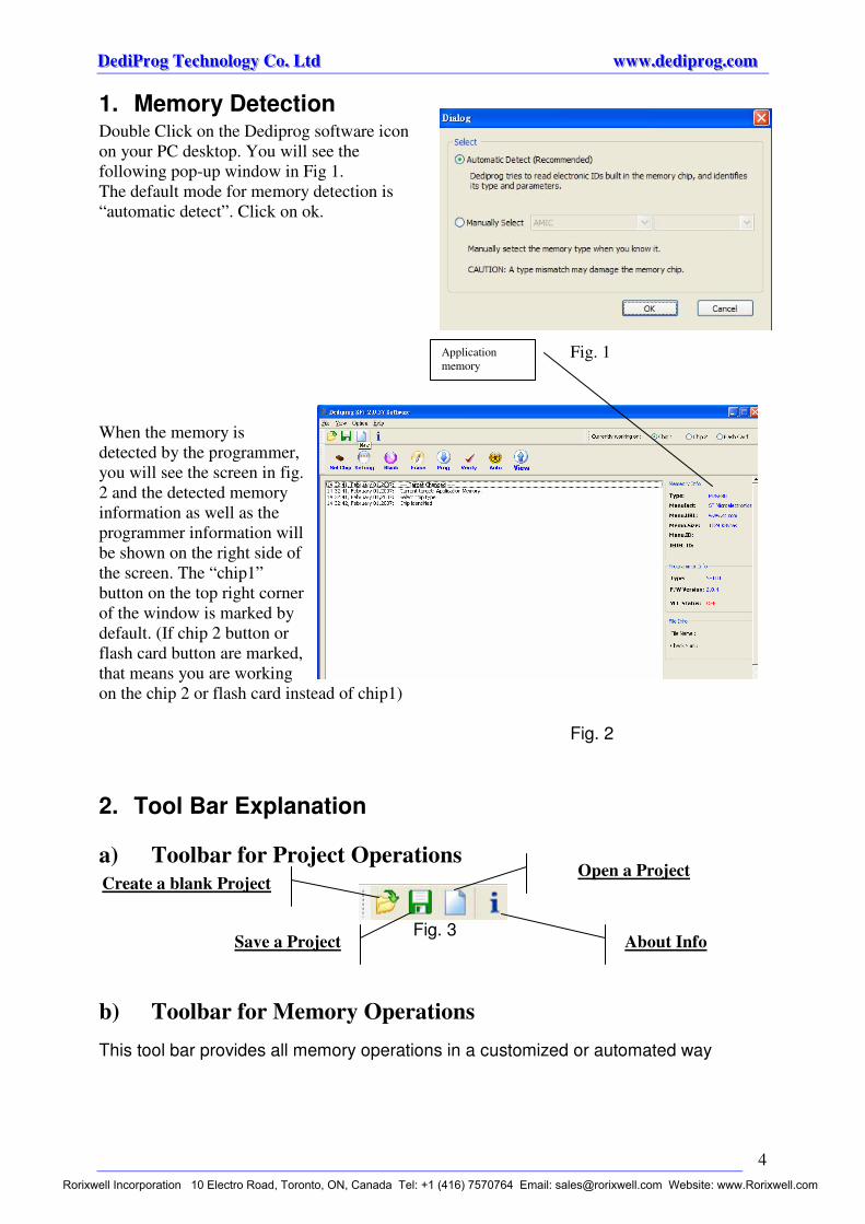
1. Memory Detection Double Click on the Dediprog software icon
on your PC desktop. You will see the
following pop-up window in Fig 1.
The default mode for memory detection is
“automatic detect”. Click on ok.
Fig. 1
When the memory is
detected by the programmer,
you will see the screen in fig.
2 and the detected memory
information as well as the
programmer information will
be shown on the right side of
the screen. The “chip1”
button on the top right corner
of the window is marked by
default. (If chip 2 button or
flash card button are marked,
that means you are working
on the chip 2 or flash card instead of chip1)
Fig. 2
2. Tool Bar Explanation
Fig. 3
This tool bar provides all memory operations in a customized or automated way
a) Toolbar for Project Operations
b) Toolbar for Memory Operations
Open a Project
Save a Project
Create a blank Project
About Info
Application
memory
Rorixwell Incorporation 10 Electro Road, Toronto, ON, Canada Tel: +1 (416) 7570764 Email: [email protected] Website: www.Rorixwell.com
DDDeeedddiiiPPPrrroooggg TTTeeeccchhhnnnooolllooogggyyy CCCooo... LLLtttddd wwwwwwwww...dddeeedddiiippprrroooggg...cccooommm
5
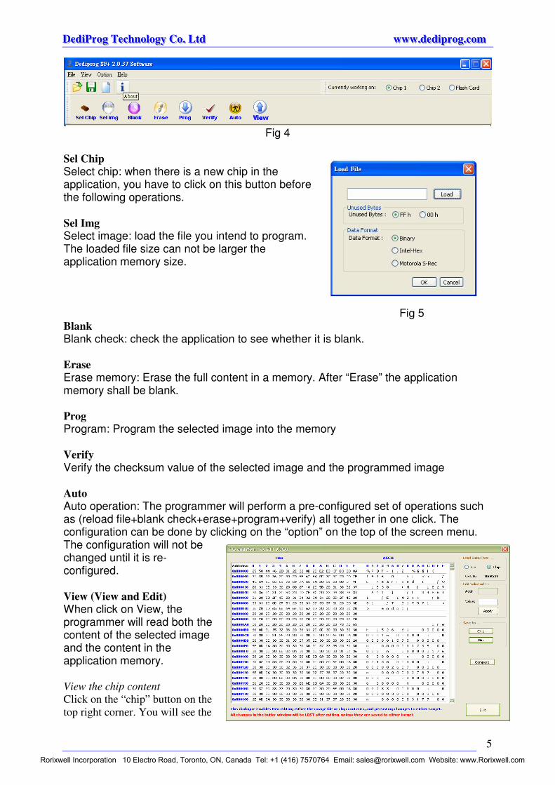
Fig 4
Sel Chip
Select chip: when there is a new chip in the application, you have to click on this button before the following operations. Sel Img
Select image: load the file you intend to program. The loaded file size can not be larger the application memory size.
Fig 5 Blank
Blank check: check the application to see whether it is blank. Erase
Erase memory: Erase the full content in a memory. After “Erase” the application memory shall be blank. Prog
Program: Program the selected image into the memory Verify
Verify the checksum value of the selected image and the programmed image Auto
Auto operation: The programmer will perform a pre-configured set of operations such as (reload file+blank check+erase+program+verify) all together in one click. The configuration can be done by clicking on the “option” on the top of the screen menu. The configuration will not be changed until it is re-configured. View (View and Edit)
When click on View, the programmer will read both the content of the selected image and the content in the application memory.
View the chip content
Click on the “chip” button on the
top right corner. You will see the
Rorixwell Incorporation 10 Electro Road, Toronto, ON, Canada Tel: +1 (416) 7570764 Email: [email protected] Website: www.Rorixwell.com

DDDeeedddiiiPPPrrroooggg TTTeeeccchhhnnnooolllooogggyyy CCCooo... LLLtttddd wwwwwwwww...dddeeedddiiippprrroooggg...cccooommm
6
content of the application chip in both Hex view and ASCII view. The checksum value is also
displayed below the “chip” button.
View the loaded image content
Click on the “file” button on the top right corner of the display screen. You will see the content
of the selected image in both Hex view and ASCII view. The checksum value is also displayed
below the “chip” button.
Edit content and save
Step1
Locate your mouse to the location where you want to change the content.
You will see the address and value of the selected contents shown in the
right frame of the content screen.
Step 2
Change the value in the value box and click on apply. The content now is changed in the
computer buffer and you will see the value is changed also in the content screen.
Step 3
In order to save the changed contents into a file or back to the application memory, you will
need to further click on save to chip or file otherwise
the content will be the same as the original file.
Compare the content of the loaded image and the
application memory
This function enables a byte by byte comparison between the selected image and the application memory. It will only display the difference between the selected image and the application memory. Option By clicking on the option you will be able to configure the set of operations perform by a single click on “auto” button. Chip 1, Chip 2, Flash Card Chip 1 is the default chip of operations. You are also able to work on a second chip or flash card.
3. Update Firmware Note: if you need to update the firmware to a higher version, please
contact Dediprog at [email protected] for the updated firmware.
Rorixwell Incorporation 10 Electro Road, Toronto, ON, Canada Tel: +1 (416) 7570764 Email: [email protected] Website: www.Rorixwell.com

DDDeeedddiiiPPPrrroooggg TTTeeeccchhhnnnooolllooogggyyy CCCooo... LLLtttddd wwwwwwwww...dddeeedddiiippprrroooggg...cccooommm
7
Step 1: connect the programmer to the PC
Step 2: open the Dediprog software
Step 3: click on “help” on the menu bar
Step 4: click on “update firmware” option
Step 5: select the location (folder) where the firmware is located
Step 6: click on “ok” when you see the pop-up window says “it takes about 15 seconds to
update, click ok to continue.”
Step7: click on “ok” and wait for the “update complete” message
4. Supported devices, Software version, Firmware version
C. flash card operations
1. Operations to prepare the flash card The flash Card is used to store the reference code to be copied to the application memories and
also to define the Stand Alone operation sequences. The flash card are manufactured and
commercialised by DediProg and are available in different densities (128Mb, 64Mb, 32Mb)
according to your code size. Each Flash Card can be used to program equal or smaller size
codes.
For example: the 64Mb Flash Card can be used to program the following Serial Flash
densities:
- 64Mb
- 32Mb
- 16Mb
Click on information
icon for information
of supported devices
and software version
Firmware
version
Rorixwell Incorporation 10 Electro Road, Toronto, ON, Canada Tel: +1 (416) 7570764 Email: [email protected] Website: www.Rorixwell.com

DDDeeedddiiiPPPrrroooggg TTTeeeccchhhnnnooolllooogggyyy CCCooo... LLLtttddd wwwwwwwww...dddeeedddiiippprrroooggg...cccooommm
8
- 8Mb
- 4Mb
- 2Mb
- 1Mb
- 512Kb
Step 1: Connect SF100+ or SF200+ to a computer via the USB cable.
Step 2: Insert the flash card into the flash card header on the programmer (face in the flash
card when inserting)
Step 3: open the Dediprog
SF software. Click on
“ok” when it asks auto
select or manual select
device.
Step 4: User must select the “Flash
Card” mode on the Top Right
corner of the window. The
DediProg tool will then detect
automatically the Flash Card.
Note: the default mode of the
Dediprog SF software is
Chip1. Therefore you
will not see anything if there is
nothing in chip1.
Note: please make sure whether you are doing the programming to the application memory or
to the flash card.
Step 4: Select a file image (reference code to be copied in stand
alone mode) by clicking the
“Sel Img” button and launch the programming operation
by clicking the “Update” button.
Step 5:
select the configurations which will be used by the
flash card during standalone programming.
-Select the memory density of the target memory:
Rorixwell Incorporation 10 Electro Road, Toronto, ON, Canada Tel: +1 (416) 7570764 Email: [email protected] Website: www.Rorixwell.com

DDDeeedddiiiPPPrrroooggg TTTeeeccchhhnnnooolllooogggyyy CCCooo... LLLtttddd wwwwwwwww...dddeeedddiiippprrroooggg...cccooommm
9
please make sure that it is the density size of the target memory not the density of the flash card
to be selected
- Blank Check option: to check in Stand Alone if all the application memory is erased.
- Erase: to Erase in Stand Alone all the target memory. If the previous “Blank Check” option
has been selected then the erase operation will be performed only if the memory is not blank.
- Program: To program in Stand Alone mode, the reference code stored in the Flash Card to
the target memory.
- Verify: To check if the target memory content has been well programmed
- Protect: To protect the memory by setting the protection bit
- Vpp: To apply the Vpp high voltage on the Wp pin of the Serial Flash and speed up the
programming and erasing operation. To be selected only if the target memory can support it.
Example:
Scenario
1. Flash card density: 64M bit
2. Application memory size: STM 32M bit
3. Application memory supports Vpp capability
4. Application memory does not need to be protected after programming
5. Application Memory is all blank
Flash card configuration: STM 32M, Program, Verify, support VPP
Step 6:
Click ok after you have done your selection in step 5 and then wait for the completion message.
All the standalone operations with this flash card will be based on the selections you have
made in step 5.
Your Flash Card is now ready to be used in Stand alone mode. It is advised to mark the code
revision on the Flash Card to not make any mixing in production. You can then prepare all the
Flash Cards needed by each programmer used in production.
2. Read Programming History Step 1: insert the flash card into the programmer and connect the programmer to a PC.
Step 2: open Dediprog SF+ software and select “flash card” on the top right corner when
entering into the main screen
Step 3: click on
“History” button on the tool
bar and you will see
the operation
statistics pop-up
window shown in the
right.
Step 4: click on ok if you
want to keep the
statistics and
continue to use the
flash card. Click on
reset if you want to
Rorixwell Incorporation 10 Electro Road, Toronto, ON, Canada Tel: +1 (416) 7570764 Email: [email protected] Website: www.Rorixwell.com

DDDeeedddiiiPPPrrroooggg TTTeeeccchhhnnnooolllooogggyyy CCCooo... LLLtttddd wwwwwwwww...dddeeedddiiippprrroooggg...cccooommm
10
erase the statistics and continue to use the card and restart to count the statistics.
Note: the standalone programming statistics can only be erased here. Erase the statistics here
will not erase the flash card content and its operation configuration you have done in
section “program the flash card.” By re-program the flash card, it does not erase or reset
the statistics stored in the flash card.
A.Dediprog Windows DOS Command Line Support Display
B.How to Start Dediprog window dos command line software is executed by the file “dpcmd.exe.” There are
three different ways to run the dos command line.
1. double click on the “dpcmd” icon on your desktop and type in dpcmd and enter.
2. change your dos directory to the same location where “dpcmd.exe” is located. C:\program
files\dediprog inc\dedipro programmer
3. or type in the following command to auto direct the dpcmd command to the “dpcmd.exe”
location.
Set path=%path%;”c:\program files\dediprog inc\dedipro programmer”
III. Dediprog Windows DOS Command Line Software User Guide
Rorixwell Incorporation 10 Electro Road, Toronto, ON, Canada Tel: +1 (416) 7570764 Email: [email protected] Website: www.Rorixwell.com

DDDeeedddiiiPPPrrroooggg TTTeeeccchhhnnnooolllooogggyyy CCCooo... LLLtttddd wwwwwwwww...dddeeedddiiippprrroooggg...cccooommm
11
C.Basic Usages: Dpcmd -uxxx
Dpcmd /uxxx
Dpcmd --auto=xxx
(space is not needed between the switches parameters. E.g. dpcmd -ubio.bin)
D.Usage Examples: 1. dpcmd -r"f:\file.bin",
reads the chip and save it into a file "file.bin"
2. dpcmd -rSTDOUT -a0x100 -l0x23,
reads 0x23 bytes starting from 0x100 and display it on the screen
3. dpcmd -ufile.bin,
erases and then program file.bin into the serial flash
4. dpcmd -pfile.bin -a0x100,
writes file.bin into the serial flash starting from address 0x100
5. dpcmd -pfile.bin -x0xaa,
programs file.bin into the serial flash and fill the rest area with 0xaa
Remarks: -a, -l only works with -p, -r, -s
Remarks: -x only works with -p
E. Basic Switches: -? [ --help ] show the help message with examples
-d [ --detect ] detect chip
-b [ --blank ] blank check
-e [ --erase ] erase entire chip
-r [ --read ] arg read chip contents and save to a bin/hex/s19 or STDOUT to the console.
-p [ --prog ] arg program chip without erase
-u [ --auto ] arg automatically run the following sequence:
- check if the chip is blank or not);
- erase the entire chip(if not blank);
- program a whole file starting from address 0
-s [ --sum ] display chip content checksum
-f [ --fsum ] arg display the file checksum(needs to work with a file)
F. Optional Switches (specify the following switches to change default values):
-x [ --fill ] arg fill the rest of the chip with an hex value,
- works with --prog only
-a [ --addr ] arg starting address(e.g. 0x1000),
- works with --prog, --read and --sum only
- defaults to 0, if omitted.
-l [ --length ] arg length to read/program in bytes,
- works with --prog, --read and --sum only
- defaults to whole file if omitted
-t [ --timeout ] arg (=300) Timeout value in seconds
Rorixwell Incorporation 10 Electro Road, Toronto, ON, Canada Tel: +1 (416) 7570764 Email: [email protected] Website: www.Rorixwell.com

DDDeeedddiiiPPPrrroooggg TTTeeeccchhhnnnooolllooogggyyy CCCooo... LLLtttddd wwwwwwwww...dddeeedddiiippprrroooggg...cccooommm
12
-g [ --target ] arg (=1) Target Options
Available values:
1. chip 1(Default)
2. chip 2
0. flash card
For more information please contact us or your motherboard suppliers.
We also recommend motherboard makers to enter in contact with our technical team to create a
dedicated document that will take into consideration all your motherboard updating constraints
and references. This documentation will then be very helpful to simplify the Bios update and
avoid any mistake in the field.
Information furnished is believed to be accurate and reliable. However, DediProg assumes no
responsibility for the consequences of use of such information nor for any infringement of
patents or other rights of third parties which may result from its use. Specifications mentioned
in this publication are subject to change without notice.
This publication supersedes and replaces all information previously supplied.
All rights reserved
Printed in Taiwan.
Rorixwell Incorporation 10 Electro Road, Toronto, ON, Canada Tel: +1 (416) 7570764 Email: [email protected] Website: www.Rorixwell.com