DECOMMISSIONING PLAN for NAVAL AIR WEAPONS STATION … · Decommissioning Plan NAWS China Lake...
149
Revision 3 – 7/2/2007 DECOMMISSIONING PLAN for NAVAL AIR WEAPONS STATION (NAWS) CHINA LAKE Prepared by New World Technology 448 Commerce Way Livermore, CA 94551 Enclosure (8)
Transcript of DECOMMISSIONING PLAN for NAVAL AIR WEAPONS STATION … · Decommissioning Plan NAWS China Lake...
Revision 3 – 7/2/2007
DECOMMISSIONING PLAN
for
NAVAL AIR WEAPONS STATION (NAWS)
CHINA LAKE
Prepared by
New World Technology
448 Commerce Way
Livermore, CA 94551
Enclosure (8)
Decommissioning Plan NAWS China Lake
Revision 3 – 7/2/2007 i
TABLE OF CONTENTS
1.0 EXECUTIVE SUMMARY _______________________________________________ 10
1.1 Background Information _____________________________________________ 10
1.2 Decommissioning Objectives __________________________________________ 11
1.3 ALARA Evaluations (Revise to summarize analysis of Section 7.0) __________ 12
1.4 Derived Concentration Guideline Limits (DCGLs) ________________________ 13
1.5 Schedule ___________________________________________________________ 14
1.6 Post Remediation Activities ___________________________________________ 14
1.7 License Amendment _________________________________________________ 14
2.0 FACILITY OPERATING HISTORY ______________________________________ 14
2.1 Current License Number/Status _______________________________________ 17
2.2 Current Authorized Activities _________________________________________ 17
2.3 License and Naval Radioactive Material Permit History ___________________ 17
2.4 Locations Potentially Impacted by Licensed and Non-Licensed DU Activities at
China Lake (Historical Review) _____________________________________________ 20 2.4.1 Kennedy Stands Target Area _________________________________________ 20 2.4.2 K-2 Gunnery Range ________________________________________________ 21 2.4.3 Tower 11 Range ___________________________________________________ 22
2.4.4 G-6 Range ________________________________________________________ 28
2.4.5 Burro Canyon-Dead Man’s Canyon ____________________________________ 30 2.4.6 Building 10520 Range ______________________________________________ 30 2.4.7 T-Range Burning Ground (IR Site 6) __________________________________ 31
2.4.8 Skytop, Skytop Playa, Mineshafts _____________________________________ 31 2.4.9 Boondock Facility __________________________________________________ 31
2.4.10 Building 10632 __________________________________________________ 31 2.4.11 Supersonic Naval Ordnance Research Track (SNORT) ___________________ 31
2.4.12 Building 10522 __________________________________________________ 32 2.4.13 Building 10524 __________________________________________________ 32 2.4.14 Building 10540 __________________________________________________ 32 2.4.15 Building 10562 __________________________________________________ 32
2.4.16 Building 10630 __________________________________________________ 32 2.4.17 Building 11640 __________________________________________________ 32 2.4.18 Building 11681 __________________________________________________ 32
2.4.19 Building 15570 __________________________________________________ 32 2.4.20 Building 30594 __________________________________________________ 32 2.4.21 Building 31003 __________________________________________________ 32 2.4.22 Building 31018 __________________________________________________ 33 2.4.23 Building 31110 __________________________________________________ 33

Decommissioning Plan NAWS China Lake
Revision 3 – 7/2/2007 ii
2.4.24 Building 15510 __________________________________________________ 33
2.4.25 CT Area ________________________________________________________ 33 2.4.26 Building 15560 __________________________________________________ 33 2.4.27 Magazette 45M-4-13 ______________________________________________ 33
2.4.28 Airport Lake ____________________________________________________ 33 2.4.29 B-1-B Range ____________________________________________________ 33 2.4.30 B-4 Range ______________________________________________________ 34 2.4.31 Building 10634 __________________________________________________ 34 2.4.32 Building 12520 __________________________________________________ 34
2.4.33 Building 13090 __________________________________________________ 34 2.4.34 Building 13110 __________________________________________________ 34 2.4.35 Building 30888 __________________________________________________ 34 2.4.36 Building 30973 __________________________________________________ 34
2.4.37 Cole Flats ______________________________________________________ 34 2.4.38 Coso Military Target Range ________________________________________ 35
2.4.39 G-1 Range ______________________________________________________ 35 2.4.40 G-2 Range ______________________________________________________ 35
2.4.41 LC Ranges ______________________________________________________ 35 2.4.42 Off-Station Target-1 (OST-1) Range _________________________________ 35 2.4.43 Salt Wells Pilot Plant (SWPP) Facility ________________________________ 35
2.4.44 Building 15700 __________________________________________________ 35 2.4.45 X-3 Bomb Craters ________________________________________________ 35
2.4.46 X-Pad at NAF ___________________________________________________ 36
2.5 Previous Decommissioning Activities ___________________________________ 36 2.5.1 Skytop Playa Mineshafts_____________________________________________ 37
2.5.2 Tower 11 Target Area _______________________________________________ 37
2.5.3 Site 6 Burn Facility (T-Range Burn Pits) ________________________________ 38 2.5.4 Building 10520 Range (known in the historical record as Building 52) ________ 39
2.6 Spills ______________________________________________________________ 39
3.0 FACILITY DESCRIPTION _____________________________________________ 40
3.1 Site Location and Description _________________________________________ 40
3.2 Population Distribution ______________________________________________ 42
3.3 Current and Future Land Use _________________________________________ 44
3.4 Ambient Air Quality _________________________________________________ 44
3.5 Meteorology and Climatology _________________________________________ 45
3.6 Geology and Seismology ______________________________________________ 46
3.7 Surface Water Hydrology ____________________________________________ 47
3.8 Groundwater Hydrology _____________________________________________ 47
3.9 Natural Resources ___________________________________________________ 49
3.10 Environmentally/Archaeologically Sensitive Areas ________________________ 49

Decommissioning Plan NAWS China Lake
Revision 3 – 7/2/2007 iii
4.0 RADIOLOGICAL STATUS OF FACILITY ________________________________ 50
4.1 Contaminated Ranges ________________________________________________ 50 4.1.1 Aerial Surveys _____________________________________________________ 50 4.1.2 Kennedy Stands ___________________________________________________ 50
4.1.3 K-2 Gunnery Range ________________________________________________ 55 4.1.4 K-2 Gunnery Range (Berm and Area Behind Berm) _______________________ 62 4.1.5 Waste Profile Samples of K-2 Berm ____________________________________ 64 4.1.6 G-6 Range ________________________________________________________ 64
4.2 Contaminated Systems and Equipment _________________________________ 68
4.3 Subsurface Soil Contamination ________________________________________ 76 4.3.2 Kennedy Stands Area _______________________________________________ 76 4.3.3 K-2 Gunnery Range ________________________________________________ 76
4.3.4 Tower 11 Area ____________________________________________________ 76
5.0 DOSE MODELING ____________________________________________________ 76
5.1 Site Conceptual Model _______________________________________________ 76 5.1.2 Source Term ______________________________________________________ 77 5.1.3 Physical Characteristics of the Site _____________________________________ 78
5.1.4 Plausible Human Exposure Scenarios and Pathways _______________________ 79
5.2 Unrestricted Release Using Site-Specific Information (K-2 Gunnery Range
(Minus Berm)-Tower 11 Area, Kennedy Stands Area) ___________________________ 81 5.2.1 RESRAD Version 6.3 Calculations ____________________________________ 81 5.2.2 Sensitivity Analysis ________________________________________________ 83
6.0 ALTERNATIVES CONSIDERED AND RATIONALE FOR CHOSEN
ALTERNATIVE _____________________________________________________________ 84
6.1 Alternatives Considered ______________________________________________ 84
6.2 Rationale for Chosen Alternative ______________________________________ 85
7.0 ALARA ANALYSIS ____________________________________________________ 86
8.0 PLANNED DECOMMISSIONING ACTIVITIES ___________________________ 88
8.1 General considerations for the Planning of Decommissioning Activities ______ 88
8.2 Scope of Planned Decommissioning Activities ____________________________ 89
8.3 Kennedy Stands Target Area __________________________________________ 91
8.4 K-2 Gunnery Range _________________________________________________ 93
8.5 Tower 11 Target Area _______________________________________________ 95
8.6 Contaminated Structures _____________________________________________ 96
8.7 Contaminated Systems and Equipment _________________________________ 97
8.8 Schedules __________________________________________________________ 97
9.0 PROJECT MANAGEMENT AND ORGANIZATION ________________________ 98
Decommissioning Plan NAWS China Lake
Revision 3 – 7/2/2007 iv
9.1 Decommissioning Management Organization ____________________________ 98
9.2 Decommissioning Task Management ___________________________________ 98
9.3 Decommissioning Management Positions and Qualifications _______________ 99 9.3.1 Project Manager ___________________________________________________ 99
9.3.2 Radiation Safety Manager ___________________________________________ 100 9.3.3 Health and Safety Manager __________________________________________ 100 9.3.4 Project Engineer __________________________________________________ 101 9.3.5 Personnel Assigned to the Project_____________________________________ 101 9.3.6 Radiation Safety Officer ____________________________________________ 102
9.4 Decontamination And Decommissioning Documents and Guides ___________ 103
9.5 Training __________________________________________________________ 105 9.5.1 Visitor Training ___________________________________________________ 105
9.5.2 General Employee Training _________________________________________ 105 9.5.3 Radiation Worker Training __________________________________________ 105 9.5.4 Tailgate Safety Training ____________________________________________ 106
9.5.5 Training Records __________________________________________________ 106
9.6 CONTRACTOR SUPPORT _________________________________________ 106
10.0 HEALTH AND SAFETY PROGRAM DURING DECOMMISSIONING ________ 107
10.1 Radiation Safety Controls and Monitoring for Workers __________________ 108
10.2 Air Monitoring Program ____________________________________________ 109
10.3 Respiratory Protection Program ______________________________________ 110
10.4 Internal and External Exposure Determination and Control ______________ 111
10.5 Exposure, Radiation and Contamination Control Program _______________ 112 10.5.1 Exposure Control _______________________________________________ 112
10.5.2 Radiation Surveys _______________________________________________ 113 10.5.3 Instrumentation Program _________________________________________ 114
10.5.4 Health Physics Audits, Inspections and Record-Keeping Program _________ 114 10.5.5 Personnel Records _______________________________________________ 115
10.5.6 Radiation and Contamination Records _______________________________ 116 10.5.7 Waste Disposal Records __________________________________________ 116
11.0 ENVIRONMENTAL MONITORING PROGRAM __________________________ 116
11.1 Effluent and Waste Monitoring Program_______________________________ 116
11.2 Effluent Control Program ___________________________________________ 117
12.0 RADIOACTIVE WASTE MANAGEMENT PROGRAM _____________________ 117
12.1 Solid Radioactive Waste (Radwaste) ___________________________________ 118
12.2 Liquid Radiation Waste _____________________________________________ 118
13.0 QUALITY ASSURANCE PROGRAM ____________________________________ 118
13.1 Organization ______________________________________________________ 118
Decommissioning Plan NAWS China Lake
Revision 3 – 7/2/2007 v
13.2 Document Control __________________________________________________ 119
13.3 Control of Measuring and Test Equipment _____________________________ 120
13.4 Corrective Action __________________________________________________ 122
13.5 Quality Assurance Records __________________________________________ 122
13.6 Audits and Surveillances ____________________________________________ 123
14.0 FACILITY RADIATION SURVEYS _____________________________________ 124
14.1 Characterization Surveys ____________________________________________ 124 14.1.2 Gamma Scan Surveys ____________________________________________ 124 14.1.3 Detection Sensitivity _____________________________________________ 124
14.1.4 Soil Sample Analysis ____________________________________________ 124
14.2 Remedial Action Support Surveys ____________________________________ 125
14.3 Final Status Survey Design and Release Criteria ________________________ 125
15.0 RESTRICTED USE CRITERIA _________________________________________ 125
16.0 FINANCIAL ASSURANCE ____________________________________________ 125
REFERENCES ____________________________________________________________ 126
Decommissioning Plan NAWS China Lake
Revision 3 – 7/2/2007 vi
LIST OF FIGURES
Figure 1 Early Map of NOTS China Lake Showing Target Ranges and Base Facilities (Ref. D-
162) .......................................................... 15
Figure 2 K-2 Range Target Berm ....................................... 21
Figure 3 Oxidized depleted uranium rounds on ground at K-2 Range ................ 22
Figure 4 Catch box and target area at target end of Tower 11 Range prior to removal and
excavation ...................................................... 23
Figure 5 Close view of catch box and target area at Tower 11 Range prior to removal and
excavation ...................................................... 23
Figure 6 2005 view of Tower 11 target 3000 meters from gun mount area: structure at left of
center housed high-speed cameras ....................................... 24
Figure 7 2005 view of Tower 11 target with catch box removed and rock excavated ...... 25
Figure 8 2005 view of Tower 11 target area from above target: trailer and tank left by clean up
contractor ....................................................... 25
Figure 9 2005 view of Tower 11 target area soil showing uranium oxide and metal fragments 26
Figure 10 2005 view of Tower 11 contractor equipment storage area looking north toward target.............................................................. 27
Figure 11 2005 view of Tower 11 contractor equipment storage area general overview .... 27
Figure 12 Aerial Photograph of G-6 Range Showing DU Dispersion ................ 29
Figure 13 G-6 Range looking west from Phalanx mount area ..................... 29
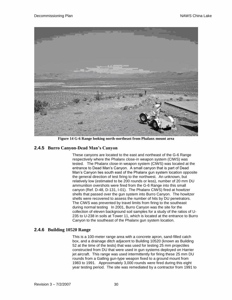
Figure 14 G-6 Range looking north-northeast from Phalanx mount area .............. 30
Figure 15 General Map of NAWS China Lake North Range Showing DU Impacted Sites (Ref.
D-149) ......................................................... 41
Figure 16 General Map of NAWS China Lake and Surrounding Areas ............... 42
Figure 17 EPA Class 1 Areas .......................................... 45
Figure 18 Kennedy Stands Survey Map ................................... 52
Figure 19 Kennedy Stands KIWI survey Data Map ............................ 52
Figure 20 K-2 Gunnery Range Reference Coordinate System ..................... 58
Figure 21 K-2 Gunnery Range Surface/Subsurface Soil Concentration Map (Southern Section).............................................................. 59
Figure 22 K-2 Gunnery Range Surface/Subsurface Soil Concentration Map (Northern Section).............................................................. 60
Figure 23 Area Behind K-2 Berm Survey Map .............................. 63
Figure 24 G-6 Area North Area Survey Map ................................ 67
Figure 25 G-6 South Area Survey Map ................................... 68
Figure 26 Kennedy Stands Area Target Map ................................ 69
Figure 27 Overall Site Map ........................................... 90
Figure 28 Kennedy Stands Area Map ..................................... 92
Figure 29 Kennedy Stands Target Map .................................... 97

Decommissioning Plan NAWS China Lake
Revision 3 – 7/2/2007 vii
LIST OF TABLES
Table 1 Summary of License Activities ................................... 17
Table 2 License/Permit History ......................................... 18
Table 3 Areas at China Lake Previously Remediated .......................... 36
Table 4 Site 6 Soil Sample Summary ..................................... 39
Table 5 Schools in the Vicinity of NAWS China Lake ......................... 43
Table 6 Kennedy Stands Firing Summary Table .............................. 53
Table 7 K-2 Gunnery Range Background Reference Area Sample Summary Table ....... 56
Table 8 K-2 Gunnery Range Sample Summary Table .......................... 61
Table 9 K-2 Berm Soil Sample Results ................................... 64
Table 10 TEDE Dose Calculation Summary Table ............................ 81
Table 11 Summary of Pathway Selections.................................. 82
Table 12 Key Parameters Used in RADRAD Scenarios ......................... 83
Table 13 Sensitivity Analysis Results Summary .............................. 84
Table 14 Parameter Values for Calculating the Ratio of ConcA to DCGLW ............. 87
Table 15 Decommissioning Schedule ..................................... 97

Decommissioning Plan NAWS China Lake
Revision 3 – 7/2/2007 viii
ACRONYMS & ABBREVIATIONS
AEC Atomic Energy Commission
AFSC U. S. Army Field Support Command
ALARA as low as is reasonably achievable
ANSI American National Standards Institute
bgs below ground surface
Bq Becquerel
CAA Civil Aeronautics Authority
CAL California
CEDE committed effective dose equivalent
CFR Code of Federal Regulations
Ci curie
CIWS close-in weapon system
cpm counts per minute
DCGL derived concentration guideline level
DoD Department of Defense
DOE Department of Energy
DOT Department of Transportation
DP decommissioning plan
dpm disintegrations per minute
DQA data quality assessment
DQO data quality objective
DTSC California Department of Toxic Substances Control
DU depleted uranium (U-238)
EA Environmental Assessment
EIS Environmental Impact Statement
EOD explosive ordnance disposal
EMC elevated measurement comparison
EPA Environmental Protection Agency ◦F degrees Fahrenheit
FSS final status survey
FSSP final status survey plan
FSSR final status survey report
ft foot
ft2 square foot
ft3 cubic foot
g gram
HE high explosive
HRA Historical Radiological Assessment (similar to a MARSSIM Historical Site Assessment)
HSA Historical Site Assessment
IC institutional control
ICRP International Commission on Radiological Protection
LA license amendment
LBGR lower bound [of the] gray region
MARSSIM Multi-Agency Radiological Survey and Site Investigation Manual (NUREG-1575)
mCi millicurie
MDA minimum detectable activity
MDC minimum detectable concentration
mm millimeter
MML Master Materials License
MOU Memorandum of Understanding
mph miles per hour
mrem millirem
msl mean sea level
mSv millisievert

Decommissioning Plan NAWS China Lake
Revision 3 – 7/2/2007 ix
NaI sodium iodide
NAWS Naval Air Weapons Station
NIST National Institute of Standards and Technology
NOAA National Oceanic and Atmospheric Administration
NORM Naturally Occurring Radioactive Material
NOTS Naval Ordnance Test Station
NRC Nuclear Regulatory Commission
NRDL Naval Radiological Defense Laboratory
NRMP Naval Radioactive Materials Permit
NRSC Naval Radiation Safety Committee
NWT New World Technology, Inc
OSHA Occupational Safety and Health Administration
pCi picocurie
pCi/g picocurie per gram
PM Project Manager
ppm parts per million
PSR partial site release
QA Quality Assurance
QAPP Quality Assurance Project Plan
QA/QC Quality Assurance and Quality Control
RASO Naval Sea Systems Command Detachment Radiological Affairs Support Office
REMP Radiological Environmental Monitoring Program
RG Regulatory Guide (also known as Reg Guide)
RME reasonable maximum exposure
RSO Radiation Safety Officer
RWP Radiation Work Permit
SDMP Site Decommissioning Management Plan
SOP Standard Operating Procedure
Sv sievert
TEDE total effective dose equivalent
Th thorium
Th-228 thorium-228
Th-230 thorium-230
Th-232 thorium-232
TI transport index
TLD thermoluminescent dosimeter
U uranium
U-234 uranium-234
U-235 uranium-235
U-238 uranium-238
UXO unexploded ordnance
USGS US Geological Survey
WRS Wilcoxon Rank Sum test
Decommissioning Plan NAWS China Lake
Revision 3 – 7/2/2007 10
1.0 EXECUTIVE SUMMARY
1.1 Background Information
This Decommissioning Plan (DP) describes the decommissioning of depleted uranium (DU) at three target ranges at the Naval Air Weapons Station (NAWS) China Lake, California. The Naval Air Weapons Station China Lake is owned by the U.S. Department of the Navy. The address for NAWS China Lake is: 1 Administration Circle, China Lake, CA 93555-6001. The DP was developed using guidance from NUREG-1757, Consolidated NMSS Decommissioning Guidance, NUREG-1575, Multi-Agency Radiological Survey and Site Investigation Manual (MARSSIM) and the regulations of 10 CFR 20, subpart E. NAWS is the site of an active, principal Naval Air Weapons Division weapons research, development, testing and evaluation (RDT&E) laboratory and test ranges for the U. S. Navy and the Department of Defense (DoD). The laboratories and test ranges have been in continuous operation since establishment in November 1943. NAWS is located in the upper Mojave Desert of Southern California surrounded by largely undeveloped, public land.
This decommissioning plan was developed for three target ranges at NAWS China Lake: Tower 11, K-2 and the Kennedy Stands; that were used to test pyrophoric and armor-piercing ammunition containing DU. Early testing was done under the regulatory framework of the Atomic Energy Commission (AEC), and later under US Nuclear Regulatory Commission (NRC) License SUB-683. In 1987, the NRC issued the Navy a Master Materials License (MML). This license allows the Navy to issue Naval Radioactive Materials Permits (NRMPs) to its facilities and organizations that use radioactive materials or devices that generate penetrating ionizing radiation. A NRMP was issued to China Lake in lieu of SUB-683 in April 1987 (Ref. D-118). The current NRMP under which the DU on the ranges is being controlled is 04-68937-L1NP (Ref. L-01). The licensing process and a history of radioactive material licensing at China Lake are detailed in Sections 2.1 and 2.2 and 2.3 below.
As a result of testing munitions containing DU, the three ranges have residual DU rounds, fragments and oxidation products extant. A fourth DU range, G-6, will not be decommissioned at this time as it remains an active target range. In addition to residual DU rounds, fragments and oxidation products, target vehicles contaminated with DU remain at the Kennedy Stands site. All testing activities at NAWS China Lake were discontinued in the early 1990s.
The three ranges are also contaminated with residual unexploded ordnance (UXO) and other ammunition and testing scrap. They will have to be cleared by explosive ordnance disposal (EOD) teams prior to, or in conjunction with, any decommissioning activities before the ranges could be returned to use as civilian assets. Use of the three ranges, for any purpose other than as dormant potential test ranges, is not likely (Ref. D-47, D-170).
Research, testing, storage and evaluation of DU used in ordnance and propellant (including simulated nuclear weapons shapes, rocket motor propellant with DU as an additive, and pyrophoric armor-piercing munitions) and disposal of DU waste were conducted at many sites on the NAWS North Range. Basic information on each of the sites/areas where DU was used, stored, or disposed of follows in the sections below and is summarized in Attachment 1. No actions are recommended or planned for sites used by the AEC for license exempt weapons development operations that used DU. A review of the buildings where depleted uranium was used, stored or processed and performing screening surveys as necessary to ensure no depleted uranium remains is a necessary further action. Any reviews or scoping surveys will be performed as separate actions from this DP. Discovery of
Decommissioning Plan NAWS China Lake
Revision 3 – 7/2/2007 11
DU contamination during scoping surveys will be addressed in a separate DP for those areas.
The ranges have been studied by respected national laboratories and universities for the health and environmental impacts of the depleted uranium remaining from DU munitions testing. Several characterization and scoping surveys have been performed by both the U.S. Navy and various contractor companies and organizations. The methodologies and conclusions presented in this DP are largely based on the results and conclusions of those studies and surveys.
Studies were undertaken by the Argonne National Laboratory and the University of Massachusetts-Amherst in 2002 and 2003 to determine the mobility of DU in the soil at NAWS (Ref. D-149) and to provide a detailed dose/risk study of the DU as it currently exists on the ranges. The summary of those studies concluded that DU is not mobile in the soil and hydrological conditions existing at NAWS China Lake and that the reasonable maximum exposure (RME) in any likely exposure scenario would be approximately 23 mrem/y.
Given the desert environment and the rate at which groundwater is being removed from the aquifer that underlies the base, no alternative use model as suggested in NUREG 1757, where an individual could be exposed to 25 mrem/y Total Effective Dose Equivalent (TEDE), is considered likely far into the foreseeable future.
NAWS China Lake poses a unique set of conditions that are best addressed by meeting the Decommissioning Plan requirements of a Group 4 facility, as described in NUREG 1757 and the provisions of 10 CFR 20 1404:
the site is contaminated with discretely located depleted uranium which is distributed over large land areas
the site is an active weapons testing range contaminated with unexploded ordnance, making collection of depleted uranium projectiles and fragments below the surface an extremely hazardous and expensive operation
the presence of natural uranium in the rocks and soils at the site make field detection of low levels of depleted uranium difficult, except by expensive surveying and sampling methods
the site has no practical alternative uses for the foreseeable future
migration of depleted uranium from penetrators and fragments in the sand/soil has been shown to be extremely slow, and the depleted uranium that does migrate from the penetrators and fragments remains well within the current boundaries of the sites in the arid conditions present at NAWS China Lake
there is a natural clay barrier beneath the sand/soil that effectively prevents the depleted uranium from migrating to the groundwater aquifer (underneath Kennedy Stands and G-6 ranges)
doses in excess of 25 mrem/y from the depleted uranium, as it currently exists on the ranges, are highly unlikely based on the referenced, detailed, dose assessment
as a U. S. Navy facility, sufficient institutional controls are in place, and will remain in place far into the foreseeable future, to prevent inadvertent intrusions and exposures
1.2 Decommissioning Objectives
The decommissioning objectives proposed by this DP are:
Release of the K-2 Gunnery Range Area for Unrestricted Use
Decommissioning Plan NAWS China Lake
Revision 3 – 7/2/2007 12
Release of the Tower 11 Target Area for Unrestricted Use
Release of the Kennedy Stands Area for Unrestricted Use
The intended actions of this decommissioning plan are to:
Remove the target vehicles, along with some other target related material including a truck carcass, tank turret and steel catch box, for disposal as radioactive waste.
Remove DU projectiles, projectile fragments and oxidation products for disposal.
Surveys utilizing appropriate radiation detection instrumentation will be used to detect DU to 15 centimeters (cm) in the sand/soil. DU and DU contaminated soils detected by these surveys will be excavated and shipped for disposal.
It is neither likely nor cost-effective to remove all residual DU. However, sufficient material will be removed to ensure no personnel accessing these sites under the presented scenarios could receive a TEDE of >25 mrem/y, and to provide for ALARA considerations.
1.3 ALARA Evaluations (Revise to summarize analysis of Section 7.0)
A goal during decommissioning activities will be to keep personnel exposure ALARA. This will be accomplished by the following but will not be limited to:
Use of Standard Operating Procedures
Internal and External Exposure Monitoring
Use of Engineering Controls
Use of Administrative Controls
Proper training of personnel involved in decommissioning activities
A pre-remediation As Low As Reasonably Achievable (ALARA) analysis has been completed to evaluate whether it is reasonable to further reduce the allowable levels of residual radioactivity to levels below those necessary to meet the dose criteria (i.e., to levels that are ALARA below the Derived Concentration Guideline Limit (DCGL)). Based on the Navy’s decision to implement the NRC’s unilaterally approved annual dose limit of 25 mrem/year Total Effective Dose Equivalent (TEDE) under the unrestricted use criteria as stated in 10 CFR §20.1402 (NRC 1997a), and given that potential exposure at the site is associated with bulk quantities of subsurface soils containing residual radioactivity (as opposed to discrete sources of radioactivity associated with systems, materials, or building structures), it is accepted on an a priori basis that compliance with the unrestricted use release criteria is ALARA.
Decommissioning guidance published by the NRC (NRC 2000a) supports the rationale that concentrations of residual radioactivity in bulk soils at a DCGL corresponding to 25 mrem/y cannot reasonably be further reduced within the context of the ALARA principle. NUREG-1727, Appendix D, Section 1.5 states: “In certain circumstances, the results of an ALARA analysis are known on a generic basis and an analysis is not necessary. For residual radioactivity in soil at sites that will have

Decommissioning Plan NAWS China Lake
Revision 3 – 7/2/2007 13
unrestricted release, generic analysis show that shipping soil to a low-level waste disposal facility is unlikely to be cost effective for unrestricted release, largely because of the high cost of waste disposal. Therefore shipping soil to a low level waste disposal facility generally does not have to be evaluated [to determine whether it is ALARA] for unrestricted release.”
Based on these factors, it was determined that the proposed remedial action DCGLs are ALARA, and no remedial action that is intended to reduce concentrations of residual radioactivity in soil below the proposed remedial action DCGLs is warranted.
1.4 Derived Concentration Guideline Limits (DCGLs)
The DCGL for release of the ranges is 120 pCi/g of DU. This concentration results in a TEDE of approximately 21 mrem/y.
The DCGL was calculated using the RESRAD Version 6.3 modeling code.
The total calculated dose (TEDE) from all radionuclides was 21 mrem/year.
The four exposure scenarios that were calculated using the RESRAD Version
6.3 modeling code are:
Residential Farmer
Range Worker
Archaeologist
Trespasser
The results of the RESRAD Version 6.3 calculations are summarized in Table 1
below.
Table 1 RESRAD Version 6.3 Calculation Summary Table
Total
Calculated
TEDE in
mrem/year
Calculated
Contributing
Dose in
mrem/year
From Ground
Exposure
Calculated
Contributing
Dose in
mrem/year
From
Inhalation
Calculated
Contributing
Dose in
mrem/year
From Soil
Ingestion
Archaeologist 21 16 2.8 2.3
Range Worker 20 16 2.8 1.2
Trespasser 20 16 1.7 2.3
Residential
Farmer
16 9.7 1.4 1.8
A detailed discussion of how the DCGL was derived is provided in Section 5.2 of this DP.
Decommissioning Plan NAWS China Lake
Revision 3 – 7/2/2007 14
1.5 Schedule
The proposed initiation of decommissioning activities is unknown at this time due to the fact that the funding of activities supporting the decommissioning and radiological release of sites at NAWS China Lake are provided through the U. S. Government, specifically the Department of Defense, and are dependant on congressional appropriation.
It is estimated that the duration of decommissioning activities will be approximately 39 weeks once initiated.
1.6 Post Remediation Activities
No post-remediation activities have been identified and none are anticipated.
1.7 License Amendment
The Navy Master Materials License will incorporate the DP by license amendment.
2.0 FACILITY OPERATING HISTORY
In the mid-1930s, Trans-Sierra Airlines applied for a route between Fresno, California and Phoenix, Arizona. The Civil Aeronautics Authority (CAA) (Ref. W-25) granted the request with the provision that an emergency landing field be built in the Mojave Desert. Kern County purchased land and the Works Progress Administration (WPA) built a paved runway one mile northwest of the small town of Inyokern (1940 population 55). The airport was inaugurated in 1935. In September 1942, the airfield was requisitioned by the Army's Fourth Air Force and assigned to the Muroc Bombing Range Air Base (now Edwards Air Force Base), 50 miles to the south (Ref. W-09).
Decommissioning Plan NAWS China Lake
Revision 3 – 7/2/2007 15
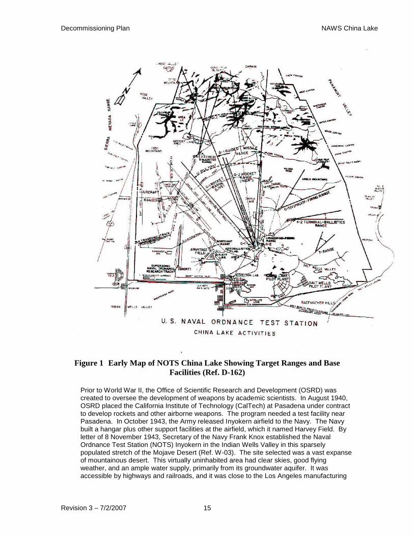
Figure 1 Early Map of NOTS China Lake Showing Target Ranges and Base
Facilities (Ref. D-162)
Prior to World War II, the Office of Scientific Research and Development (OSRD) was created to oversee the development of weapons by academic scientists. In August 1940, OSRD placed the California Institute of Technology (CalTech) at Pasadena under contract to develop rockets and other airborne weapons. The program needed a test facility near Pasadena. In October 1943, the Army released Inyokern airfield to the Navy. The Navy built a hangar plus other support facilities at the airfield, which it named Harvey Field. By letter of 8 November 1943, Secretary of the Navy Frank Knox established the Naval Ordnance Test Station (NOTS) Inyokern in the Indian Wells Valley in this sparsely populated stretch of the Mojave Desert (Ref. W-03). The site selected was a vast expanse of mountainous desert. This virtually uninhabited area had clear skies, good flying weather, and an ample water supply, primarily from its groundwater aquifer. It was accessible by highways and railroads, and it was close to the Los Angeles manufacturing

Decommissioning Plan NAWS China Lake
Revision 3 – 7/2/2007 16
area. The NOTS main base was constructed ten miles east of Inyokern. It consisted of work shops, laboratories and barracks for 60 officers and 600 men. Armitage Field air base was added in mid-1945. NOTS Inyokern, including a 900 square mile test range, was commissioned on 12 December 1943 (Ref. W-09). Development of air-launched rockets, solid propellants, fire-control systems, and rocket and guided missile testing and evaluation were NOTS' primary efforts in the 1940s. In the late 1940s, NOTS began research on fire-control systems that evolved into the Sidewinder guided missile. During World War II, the Station played a role in the Manhattan Project as the site of "Project Camel," which developed non-nuclear explosive bomb components, a role that the base continued to serve into the 1950s (Ref. W-05). Following the war, NOTS continued to be a major defense site for the development and production of rockets and missiles (Ref. W-05, W-09). The Navy closed Harvey Field in April 1946, returning it to Kern County a year later. Today it serves as the civilian Inyokern Airport (Ref. W-09). Because of its remote location, research and development facilities and accessibility to weapons laboratories at Livermore and Sandia Laboratories and the Naval Radiological Defense Laboratory (NRDL) at the Hunters Point shipyard in San Francisco, China Lake was chosen for testing non-weapons grade bomb components, which were often made from DU, and delivery systems designed for use with atomic weapons (Ref. W-09, W-15). In 1950, bomb component testing started. Under the aegis of the AEC, various shapes that simulated nuclear bomb configurations were constructed from DU and air dropped at various target range locations at NOTS (Ref. D-135). High-speed testing of shapes constructed of DU and other materials was also performed on the SNORT track and the B-4 transonic test track. Known DU impacted test sites are described in Section 5.0 below. In 1967, the NOTS complex became the Naval Weapons Center (NWC), China Lake (Ref. W-03, W-09). In 1992 the NWC was disestablished and its Research, Development, Test and Evaluation (RDT&E) functions were combined with the Test and Evaluation (T&E) functions of the White Sands Missile Range and the Point Mugu Sea Range (Ref. W-09, W-15). This combination resulted in the formation of the Naval Air Warfare Center Weapons Division (NAWCWPNSDIV). The facilities, military administration, and airfield functions were consolidated into the Naval Air Weapons Station (NAWS) China Lake in March 1998. As the stockpile of DU expanded during the production of enriched uranium and plutonium for nuclear weapons and enriched uranium fuel for government and civilian power reactors during the Cold War, the military investigated uses for this dense, abundant and inexpensive material. DU powder was considered as a component for weapon propellant. Powdered DU and other propellant materials were prepared and mixed in various China Lake buildings and tested at China Lake’s rocket motor firing ranges. DU was also regarded as an excellent metal for use in pyrophoric and penetrating armor piercing rounds, and as missile-killing ammunition for shipboard weapons systems. China Lake became an active test facility for projectiles made of DU. The ranges at Kennedy Stands, K-2, Tower 11 and G-6 were the primary ranges for these tests. High speed testing was done on the supersonic track at SNORT and other gun system tests were performed at Building 10520 and the CT site. Testing of DU munitions at NAWS ceased in 1991. Testing atomic weapons shapes by using DU as a substitute for the enriched uranium normally present in such weapons was done by the AEC beginning in 1946 and continuing into the early 1960s. These weapons shapes were tested at a variety of sites at NAWS during this timeframe. The shapes were usually not recovered at the times of the tests. By statute, the AEC was exempt from licensing requirements for these tests. Therefore, this activity was outside the bounds of the AEC/NRC license and NRMP and no attempts to recover these shapes or fragments of shapes are planned as part of this decommissioning project. Facilities, areas and buildings at NAWS China Lake that were potentially impacted by the use or storage of DU are described below.
Decommissioning Plan NAWS China Lake
Revision 3 – 7/2/2007 17
2.1 Current License Number/Status
The Navy is currently controlling the storage and limited uses of DU at NAWS to the requirements of NRMP No. 04-68937-L1NP. The most current version of NRMP No. 04-68937-L1NP is Amendment No. 3, which was issued on 29 August 2005 and expires on 30 September 2010. (Ref. L-01).
2.2 Current Authorized Activities
Table 2 below presents summary of current authorized license activities:
Table 2 Summary of License Activities Material Form Maximum
Quantity
Use
Uranium Depleted uranium projectiles
as metallic solid or uranium
oxide.
1500 kg
Storage, pending decommissioning, of target
vehicles and artillery on the Kennedy Stands
Air-to-Ground Test Area, Tower 11 Target
Area, K-2 Small Caliber Gun Range, and
other areas yet to be identified, contaminated
with DU projectiles and fragments as
metallic solid or as oxides of depleted
uranium. Not withstanding the storage only
use, some DU projectiles are authorized to
be recovered and be used to calibrate various
gamma detection systems used to locate DU
projectiles on the Kennedy Stands Air-to-
Ground Test Area, Tower 11 Target Area,
K-2 Small Caliber Gun Range, and other
areas as needed. Soil sampling on target
ranges and analysis by mass spectrometry is
authorized.
Uranium Depleted uranium projectiles
as metallic solid or uranium
oxide.
6500 kg Indefinite storage of DU projectiles,
fragments as metallic solids or as oxides of
depleted uranium, and soils contaminated
with fragments as metallic solids or as
oxides of depleted uranium on the G-6
Impact Area, Building 30888 and Building
465
2.3 License and Naval Radioactive Material Permit History
Naval Ordnance Test Station was issued an AEC source material license number SUB-683 on 30 January 1963, which authorized the possession and processing (including incineration and disposal) of DU (Ref. D-76). The license was amended in 1965 to permit the destructive testing of explosive or propellant materials containing DU by detonation or burning and the destruction of waste source materials. Beginning in 1969 and continuing until its termination in 1987, SUB-683 was further amended to allow the testing of DU projectiles, penetrators and pyrophoric ammunition at various ranges at China Lake. The final amendment to SUB-683, Amendment 07, permitting tests of DU ammunition and was issued on 7 September 1984.
Decommissioning Plan NAWS China Lake
Revision 3 – 7/2/2007 18
On 18 May 1987, SUB-683 was superseded by NRMP No. 04-60530-L1NP, which was superseded by NRMP No. 04-68937-L1NP on 16 March 1998, when the Naval Air Warfare Center (NAWC), Weapons Division became the Naval Air Weapons Station (NAWS) China Lake.
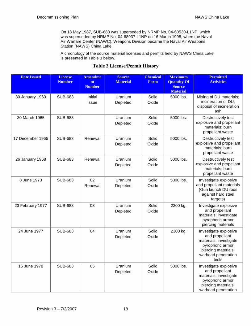
A chronology of the source material licenses and permits held by NAWS China Lake is presented in Table 3 below.
Table 3 License/Permit History
Date Issued License
Number
Amendme
nt
Number
Source
Material
Chemical
Form
Maximum
Quantity Of
Source
Material
Permitted
Activities
30 January 1963 SUB-683 Initial
Issue
Uranium
Depleted
Solid
Oxide
5000 lbs. Mixing of DU materials; incineration of DU;
disposal of incineration ash
30 March 1965 SUB-683 Uranium
Depleted
Solid
Oxide
5000 lbs. Destructively test explosive and propellant
materials; burn propellant waste
17 December 1965 SUB-683 Renewal Uranium
Depleted
Solid
Oxide
5000 lbs. Destructively test explosive and propellant
materials; burn propellant waste
26 January 1968 SUB-683 Renewal Uranium
Depleted
Solid
Oxide
5000 lbs. Destructively test explosive and propellant
materials; burn propellant waste
8 June 1973 SUB-683 02
Renewal
Uranium
Depleted
Solid
Oxide
5000 lbs. Investigate explosive and propellant materials
(Gun launch DU rods against hard steel
targets)
23 February 1977 SUB-683 03 Uranium
Depleted
Solid
Oxide
2300 kg. Investigate explosive and propellant
materials; investigate pyrophoric armor piercing materials
24 June 1977 SUB-683 04 Uranium
Depleted
Solid
Oxide
2300 kg. Investigate explosive and propellant
materials; investigate pyrophoric armor piercing materials;
warhead penetration tests
16 June 1978 SUB-683 05 Uranium
Depleted
Solid
Oxide
5000 lbs. Investigate explosive and propellant
materials; investigate pyrophoric armor piercing materials;
warhead penetration
Decommissioning Plan NAWS China Lake
Revision 3 – 7/2/2007 19
tests
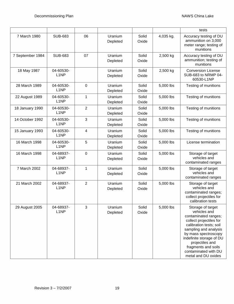
7 March 1980 SUB-683 06 Uranium
Depleted
Solid
Oxide
4,035 kg. Accuracy testing of DU ammunition on 3,000
meter range; testing of munitions
7 September 1984 SUB-683 07 Uranium
Depleted
Solid
Oxide
2,500 kg Accuracy testing of DU ammunition; testing of
munitions
18 May 1987 04-60530-L1NP
Uranium
Depleted
Solid
Oxide
2,500 kg Conversion License SUB-683 to NRMP 04-
60530-L1NP
28 March 1989 04-60530-L1NP
0 Uranium
Depleted
Solid
Oxide
5,000 lbs Testing of munitions
22 August 1989 04-60530-L1NP
1 Uranium
Depleted
Solid
Oxide
5,000 lbs Testing of munitions
18 January 1990 04-60530-L1NP
2 Uranium
Depleted
Solid
Oxide
5,000 lbs Testing of munitions
14 October 1992 04-60530-L1NP
3 Uranium
Depleted
Solid
Oxide
5,000 lbs Testing of munitions
15 January 1993 04-60530-L1NP
4 Uranium
Depleted
Solid
Oxide
5,000 lbs Testing of munitions
16 March 1998 04-60530-L1NP
5 Uranium
Depleted
Solid
Oxide
5,000 lbs License termination
16 March 1998 04-68937-L1NP
0 Uranium
Depleted
Solid
Oxide
5,000 lbs Storage of target vehicles and
contaminated ranges
7 March 2002 04-68937-L1NP
1 Uranium
Depleted
Solid
Oxide
5,000 lbs Storage of target vehicles and
contaminated ranges
21 March 2002 04-68937-L1NP
2 Uranium
Depleted
Solid
Oxide
5,000 lbs Storage of target vehicles and
contaminated ranges; collect projectiles for
calibration tests
29 August 2005 04-68937-L1NP
3 Uranium
Depleted
Solid
Oxide
5,000 lbs Storage of target vehicles and
contaminated ranges; collect projectiles for calibration tests; soil
sampling and analysis by mass spectroscopy indefinite storage of DU
projectiles and fragments and soils
contaminated with DU metal and DU oxides
Decommissioning Plan NAWS China Lake
Revision 3 – 7/2/2007 20
2.4 Locations Potentially Impacted by Licensed and Non-Licensed DU Activities at China Lake (Historical Review)
Research, testing, storage and evaluation of DU used in ordnance and propellant (including simulated nuclear weapons shapes, rocket motor propellant with DU as an additive, and pyrophoric armor-piercing munitions) and disposal of DU waste were conducted at many sites on the NAWS North Range. Basic information on each of the sites/areas where DU was used, stored or disposed of follows in the sections below and is summarized in Attachment 1. No actions are recommended or planned for sites used by the AEC for license exempt weapons development operations that used DU. A review of the buildings where depleted uranium was used, stored or processed and performing screening surveys as necessary to ensure no depleted uranium remains is a necessary further action. Any reviews or scoping surveys will be performed as separate actions from this DP. Discovery of DU contamination during scoping surveys will be addressed in a separate DP for those areas.
The historic record for all facilities where DU was or could have been used at NAWS China Lake is incomplete. Following extensive archival searches, review of available records, some of which were hand-written field notes, and interviews with knowledgeable current and retired China Lake employees, resulted in the following listing of sites where DU was known to have been, or where there is a high probability that DU had been used or disposed of at NAWS.
Several areas have been identified during this research indicating the use or storage of DU that were not previously suspected. The recommended action for those facilities is to perform a scoping survey to determine the current radiological status as an action separate from this DP. The areas, prior uses and proposed actions are summarized as Attachment 1 to this plan.
2.4.1 Kennedy Stands Target Area
This target area is approximately one mile square. It is named after viewing stands which were constructed there for a visit by President Kennedy on 25 June 1963. Beginning in December 1980 (Ref. D-122), testing at this location included Harrier jets and helicopters firing approximately 4,000 rounds of 25 mm pyrophoric antitank munitions containing DU at thirteen targets (seven tanks and six other vehicles) in two rows and five target lanes (Ref. D-48, D-69, D-70, D-73, D-93, D-120, D-121, D-125, D-126, D-131, D-133, D-134, I-01). It is estimated that the total weight of DU fired is approximately 1287 pounds. A Sheridan tank that was sparked adjacent to the target area on the range was used as a target for DU during testing in 1980. All targets have been hit by, and are contaminated with, DU. Some were equipped with radioluminescent dials and gauges containing radium-bearing paint, creating an internal contamination concern. DU penetrators and fragments are present in target vehicles. DU penetrators and fragments can also be found on and buried in the ground around and north of the target area. The targets are located atop a sand dune in an area of approximately 150 meters by 900 meters. A tank turret target (from the K-2 Gunnery Range) and steel catch box structure, which have been exposed to penetrator fire, are stored in the Kennedy Stands area. Historical Native American artifacts are present in the soil immediately south of the target area. The area containing the artifacts is considered archaeologically sensitive.
Decommissioning Plan NAWS China Lake
Revision 3 – 7/2/2007 21
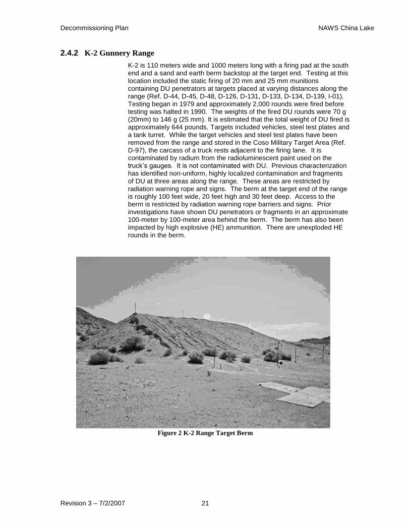
2.4.2 K-2 Gunnery Range
K-2 is 110 meters wide and 1000 meters long with a firing pad at the south end and a sand and earth berm backstop at the target end. Testing at this location included the static firing of 20 mm and 25 mm munitions containing DU penetrators at targets placed at varying distances along the range (Ref. D-44, D-45, D-48, D-126, D-131, D-133, D-134, D-139, I-01). Testing began in 1979 and approximately 2,000 rounds were fired before testing was halted in 1990. The weights of the fired DU rounds were 70 g (20mm) to 146 g (25 mm). It is estimated that the total weight of DU fired is approximately 644 pounds. Targets included vehicles, steel test plates and a tank turret. While the target vehicles and steel test plates have been removed from the range and stored in the Coso Military Target Area (Ref. D-97), the carcass of a truck rests adjacent to the firing lane. It is contaminated by radium from the radioluminescent paint used on the truck’s gauges. It is not contaminated with DU. Previous characterization has identified non-uniform, highly localized contamination and fragments of DU at three areas along the range. These areas are restricted by radiation warning rope and signs. The berm at the target end of the range is roughly 100 feet wide, 20 feet high and 30 feet deep. Access to the berm is restricted by radiation warning rope barriers and signs. Prior investigations have shown DU penetrators or fragments in an approximate 100-meter by 100-meter area behind the berm. The berm has also been impacted by high explosive (HE) ammunition. There are unexploded HE rounds in the berm.
Figure 2 K-2 Range Target Berm
Decommissioning Plan NAWS China Lake
Revision 3 – 7/2/2007 22
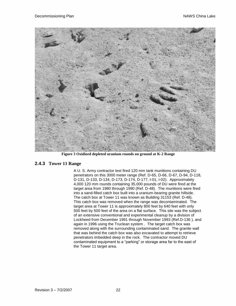
Figure 3 Oxidized depleted uranium rounds on ground at K-2 Range
2.4.3 Tower 11 Range
A U. S. Army contractor test fired 120 mm tank munitions containing DU penetrators on this 3000 meter range (Ref. D-65, D-66, D-67, D-94, D-118, D-131, D-133, D-134, D-173, D-174, D-177, I-01, I-02). Approximately 4,000 120 mm rounds containing 35,000 pounds of DU were fired at the target area from 1980 through 1990 (Ref. D-48). The munitions were fired into a sand-filled catch box built into a uranium-bearing granite hillside. The catch box at Tower 11 was known as Building 31153 (Ref. D-48). This catch box was removed when the range was decontaminated. The target area at Tower 11 is approximately 800 feet by 640 feet with only 500 feet by 500 feet of the area on a flat surface. This site was the subject of an extensive conventional and experimental cleanup by a division of Lockheed from December 1991 through November 1993 (Ref.D-136 ), and again in 1996 using the Truclean system . The target catch box was removed along with the surrounding contaminated sand. The granite wall that was behind the catch box was also excavated to attempt to retrieve penetrators imbedded deep in the rock. The contractor moved DU contaminated equipment to a “parking” or storage area far to the east of the Tower 11 target area.

Decommissioning Plan NAWS China Lake
Revision 3 – 7/2/2007 23
Figure 4 Catch box and target area at target end of Tower 11 Range prior to removal and excavation
Figure 5 Close view of catch box and target area at Tower 11 Range prior to removal and excavation

Decommissioning Plan NAWS China Lake
Revision 3 – 7/2/2007 24
Figure 6 2005 view of Tower 11 target 3000 meters from gun mount area: structure at left of center
housed high-speed cameras

Decommissioning Plan NAWS China Lake
Revision 3 – 7/2/2007 25
Figure 7 2005 view of Tower 11 target with catch box removed and rock excavated
Figure 8 2005 view of Tower 11 target area from above target: trailer and tank left by clean up
contractor
Decommissioning Plan NAWS China Lake
Revision 3 – 7/2/2007 26
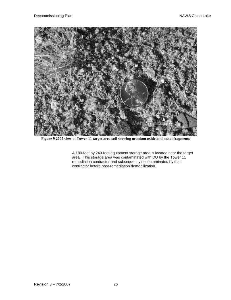
Figure 9 2005 view of Tower 11 target area soil showing uranium oxide and metal fragments
A 180-foot by 240-foot equipment storage area is located near the target area. This storage area was contaminated with DU by the Tower 11 remediation contractor and subsequently decontaminated by that contractor before post-remediation demobilization.

Decommissioning Plan NAWS China Lake
Revision 3 – 7/2/2007 27
Figure 10 2005 view of Tower 11 contractor equipment storage area looking north toward target
Figure 11 2005 view of Tower 11 contractor equipment storage area general overview
Decommissioning Plan NAWS China Lake
Revision 3 – 7/2/2007 28
2.4.4 G-6 Range
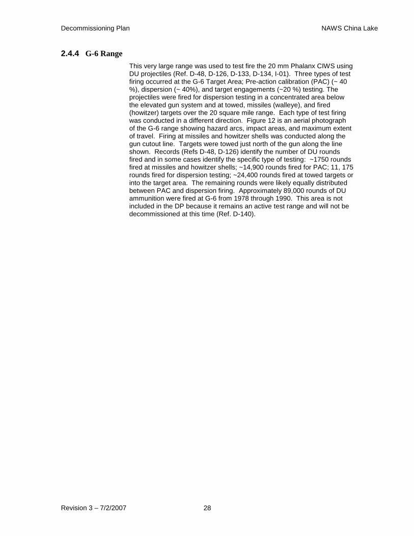
This very large range was used to test fire the 20 mm Phalanx CIWS using DU projectiles (Ref. D-48, D-126, D-133, D-134, I-01). Three types of test firing occurred at the G-6 Target Area; Pre-action calibration (PAC) (~ 40 %), dispersion (~ 40%), and target engagements (~20 %) testing. The projectiles were fired for dispersion testing in a concentrated area below the elevated gun system and at towed, missiles (walleye), and fired (howitzer) targets over the 20 square mile range. Each type of test firing was conducted in a different direction. Figure 12 is an aerial photograph of the G-6 range showing hazard arcs, impact areas, and maximum extent of travel. Firing at missiles and howitzer shells was conducted along the gun cutout line. Targets were towed just north of the gun along the line shown. Records (Refs D-48, D-126) identify the number of DU rounds fired and in some cases identify the specific type of testing: ~1750 rounds fired at missiles and howitzer shells; ~14,900 rounds fired for PAC; 11, 175 rounds fired for dispersion testing; ~24,400 rounds fired at towed targets or into the target area. The remaining rounds were likely equally distributed between PAC and dispersion firing. Approximately 89,000 rounds of DU ammunition were fired at G-6 from 1978 through 1990. This area is not included in the DP because it remains an active test range and will not be decommissioned at this time (Ref. D-140).
Decommissioning Plan NAWS China Lake
Revision 3 – 7/2/2007 29
Figure 12 Aerial Photograph of G-6 Range Showing DU Dispersion
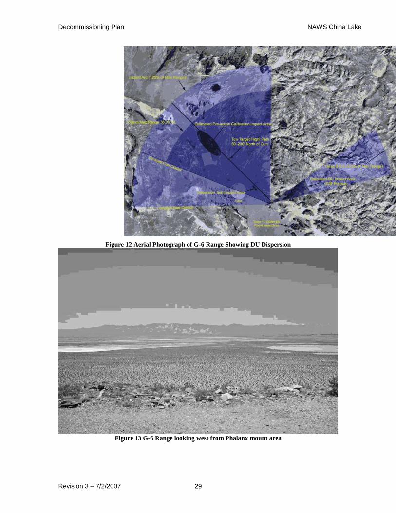
Figure 13 G-6 Range looking west from Phalanx mount area
Decommissioning Plan NAWS China Lake
Revision 3 – 7/2/2007 30
Figure 14 G-6 Range looking north-northeast from Phalanx mount area
2.4.5 Burro Canyon-Dead Man’s Canyon
These canyons are located to the east and northeast of the G-6 Range respectively where the Phalanx close-in weapon system (CIWS) was tested. The Phalanx close-in weapon system (CIWS) was located at the entrance to Dead Man’s Canyon. A small canyon that is part of Dead Man’s Canyon lies south east of the Phalanx gun system location opposite the general direction of test firing to the northwest. An unknown, but relatively low (estimated to be 200 rounds or less), number of 20 mm DU ammunition overshots were fired from the G-6 Range into this small canyon (Ref. D-48, D-131, I-01). The Phalanx CIWS) fired at howitzer shells that passed over the gun system into Burro Canyon. The howitzer shells were recovered to assess the number of hits by DU penetrators. The CIWS was prevented by travel limits from firing to the southeast during normal testing In 2001, Burro Canyon was the site for the collection of eleven background soil samples for a study of the ratios of U-235 to U-238 in soils at Tower 11, which is located at the entrance to Burro Canyon to the southeast of the Phalanx gun system location.
2.4.6 Building 10520 Range
This is a 100-meter range area with a concrete apron, sand-filled catch box, and a drainage ditch adjacent to Building 10520 (known as Building 52 at the time of the tests) that was used for testing 25 mm projectiles constructed from DU that were used in gun systems deployed on Harrier jet aircraft. This range was used intermittently for firing these 25 mm DU rounds from a Gatling gun-type weapon fixed to a ground mount from 1983 to 1991. Approximately 3,000 rounds were fired during this eight year testing period. The site was remediated by a contractor from 1991 to
Decommissioning Plan NAWS China Lake
Revision 3 – 7/2/2007 31
1996 and released for unrestricted reuse by the Navy on 8 July 1996 (Ref. D-48, D-104, D-108, D-134, D-154).
2.4.7 T-Range Burning Ground (IR Site 6)
The T-Range Burning Ground (also know as the T-Range Burn Pits) is located one-half mile west of the T-range test facility. Located on the northern flank of the Salt Wells Valley, Site 6 was an authorized location for burning DU and other waste materials. The area was divided into six discrete areas of pits, trenches and above ground tanks that were used for open burning of propellant, explosive and pyrotechnic waste, as well as DU, volatile organic compounds and cutting oils. According to the report of the contractor hired to characterize the wastes at Site 6, active burning occurred from 1946 to 1991 (Ref. D-142).
This site was a location for DU waste disposal and waste burning. From February 1962 through December 1967, approximately 2540 pounds of DU were disposed of at this burning ground. Licensed DU and thorium waste was burned only between 1964 and 1967. This activity was an authorized activity under AEC License SUB-683. This DU waste was disposed of in conjunction with the disposal of other propellant scrap at pits #2 and #3 at this facility (Ref. D-71, D-74, D-76, D-165, D-178). Burning also took place at the T Range burn pit #2 (Ref. D-76), which is also known as Area #2 per a phone conference with Jim McDonald (Refs. D-142-146).
2.4.8 Skytop, Skytop Playa, Mineshafts
The Skytop area was an authorized location for waste disposal. There were unconfirmed reports of DU waste having been disposed of in mineshafts near Skytop. Two shafts in this area were investigated and backfilled in 1981 (Ref. D-60, D-76, D-178). This action is described Section 2.5.1 below.
2.4.9 Boondock Facility
This is a test facility, located approximately one mile north of the T Range, where rocket motors with propellant containing DU powder were fired in 1964 and 1965 (Ref. D-39, D-48, D-131, D-175).
2.4.10 Building 10632
This building, known at the time as Building 63B, was used as a support facility for 1950s era simulated weapon shape tests. There was a small fire that consumed approximately 70 grams of Teflon-coated DU powder that was to be tested as rocket propellant on the dock of this building on 19 October 1965. No property damage resulted from this fire. A radiation survey immediately after the fire indicated there was no spread of uranium contamination (Ref. D-37, D-41, D-42).
2.4.11 Supersonic Naval Ordnance Research Track (SNORT)
This five-mile long supersonic track was used as a test facility for simulated nuclear weapons shapes made of DU, missile components, and DU munitions from 1975 to 1977. Records indicate only one test firing of DU munitions was made in July of 1975 (Ref. D-50). The records indicate that approximately four hundred 20 mm rounds were fired. Gun barrels

Decommissioning Plan NAWS China Lake
Revision 3 – 7/2/2007 32
made from alloys of DU (known as Tuballoy) were also reported to have been tested on the SNORT. One or more of these Tuballoy barrels reportedly self-destructed during testing (Ref. D-49, D-50, D-51, D-61, D-95, D-178). SNORT remains a highly active test facility.
2.4.12 Building 10522
DU powder sample mixing was done in this building circa 1964. The building was reported as Building 52B in the historic record (Ref. D-37, D-71, D-76).
2.4.13 Building 10524
DU powder sample mixing was done circa 1964 on the dock of this building, which was reported as Building 52D in the historic record (Ref. D-37).
2.4.14 Building 10540
There is an isolated report DU waste was picked up for incineration from this building, which was reported as Building 54 in the historic record (Ref. D-76).
2.4.15 Building 10562
DU was processed in a “Cowles Dissolver” in this building, which was reported as Building 56B in the historic record (Ref. D-37, D-76).
2.4.16 Building 10630
Differential thermal analyses on samples of DU were done in room 110 of this building, which was known as Building 63 at the time of the tests in 1963 and 1964 (Ref. D-31, D-33, D-34, D-37).
2.4.17 Building 11640
DU waste was reported to have been stored in this magazine building.
2.4.18 Building 11681
Metallurgical examinations of DU were performed in this building, which was then referred to as Building 168A (Ref. D-48, D-71, D-76, D-165, D-178).
2.4.19 Building 15570
A “magazette”, or temporary magazine, used to store DU (Ref. D-48, D-71, D-76, D-165, D-175, D-178).
2.4.20 Building 30594
DU ammunition reconditioning was performed in this building.
2.4.21 Building 31003
DU ammunition was reportedly stored in this building (Ref. D-133). The ammunition (20mm and 25mm rounds) had the DU encased in sabots

Decommissioning Plan NAWS China Lake
Revision 3 – 7/2/2007 33
which eliminated the potential for the spread of contamination, therefore no surveys were required.
2.4.22 Building 31018
DU ammunition was reportedly stored in this building (Ref. D-133).
2.4.23 Building 31110
Tow targets that had been used for tests of DU munitions, probably from Phalanx testing at the G-6 Range, were stored in this building (Ref. D-48).
2.4.24 Building 15510
This building is located in the Salt Wells Pilot Plant facility. Mixing of powdered DU was done in room 112 of this building, then known as Building 551, in 1964. Impact sensitivity testing and sample mixing of DU were also performed in room 113 in 1964 (Ref. D-33, D-34, D-37, D-71, D-76, D-165, D-175, D-178).
2.4.25 CT Area
The CT area is located in the southeast of the NAWS North Range and consists of six facilities, CT-1 through CT-6. Existing records indicate that CT-1, CT-3, CT-4 and CT-6 areas were used for burning DU powders, DU projectile firing and possible waste disposal (Ref. D-37, D-39, D-44, D-45, D-48, D-61, D-62, D-71, D-74, D-131, D-175, D-178). There are extant laboratory records of air sampling resulting from “FOPP” testing in 1964 (Ref. D-48).
2.4.26 Building 15560
This building is located in the Salt Wells Pilot Plant facility. “Stand burning” and “sensitivity tests” of DU were done in this building, known as Building 556 at the time (Ref. D-37, D-76, D-175).
2.4.27 Magazette 45M-4-13
This magazette was a temporary storage location for 25 mm DU rounds (Ref. D-133). The magazette no longer exists.
2.4.28 Airport Lake
Airport Lake is a dry lake bed at the base of the Coso Mountain Range. It is approximately fifteen miles north of Armitage Field, which is close to the southern boundary of NAWS. Simulated weapons shapes made from DU were air dropped by the AEC in this area, including the “Long Carry” or LC weapon, a modified bomb designed to penetrate concrete bunkers. This and other simulated weapons reportedly buried themselves deep in the desert floor and could not be retrieved by excavation (Ref. D-48, D-61, D-62, D-128, D-131, D-164, D-178).
2.4.29 B-1-B Range
Also known as Baker-1 and Baker-1B, B-1-B was a target range perpendicular to the Transonic Test Track B-4 (Ref. D-62, D-64). Extant records indicate that AEC weapons shapes, including those made from DU (Ref. D-131), were tested at B-1-B. Shapes known as T-63, T-64 and
Decommissioning Plan NAWS China Lake
Revision 3 – 7/2/2007 34
T-66 are mentioned in the historic record as having been tested at “Baker-1” (Ref. D-48, D-62, D-178). B-1-B is currently the designator for a target approach lane for aircraft using the G-1 Range.
2.4.30 B-4 Range
Also known as Baker-4, B-4 is the designator for the Transonic Test Track. Records indicate the track was used to test AEC weapons shapes, including those made from DU (Ref. D-48, D-62, D-64, D-76, D-131, D-178).
2.4.31 Building 10634
Known as Building 63D, this building was reportedly used as a support structure for 1950s era weapons work for tests at CT-4 (Ref. D-61). This was an AEC test site.
2.4.32 Building 12520
This building is located in the Salt Wells Pilot Plant facility. Testing of DU was suggested as potentially having been done in this building, known as Building 252 at the time (Ref. D-76, D-133, D-175). There is no confirmation of any such testing in this building in the available historic record.
2.4.33 Building 13090
Known as Building 309 in the historic record, this structure was reportedly used to store DU materials (Ref. D-76, D-165, D-175, D-178).
2.4.34 Building 13110
This structure, known as Building 311, was used to store DU materials (Ref. D-76, D-175).
2.4.35 Building 30888
Radioactive material was previously used in this building, but no precise use of the structure was found in existing documents. A contaminated bench and table was removed from this building. A contaminated section of floor, several square feet, remains. The radionuclide has not identified. This building is the Guided Missile Assembly building and is a current active storage location for DU materials and radioactive waste.
2.4.36 Building 30973
This building was mentioned as a possible location where DU was used or stored, but no precise use of the structure was found to be documented (Ref. D-133).
2.4.37 Cole Flats
AEC sponsored tests of weapons shapes, such as Big Stoop, Project R and Big Beast, were reportedly conducted in this area (Ref. D-61, D-178). It is not entirely clear from the historic record if DU was used during these tests. This was an AEC test site.
Decommissioning Plan NAWS China Lake
Revision 3 – 7/2/2007 35
2.4.38 Coso Military Target Range
This active range in the northern section of NAWS North Range was reported to have been the site to where target vehicles containing radium may have been moved to and where other DU contaminated material may have been disposed (Ref. D-48, D-97, D-128). There was also a reference to DU in the historic record from a crashed A-7 aircraft in this range (Ref. D-111). While the reference does not ascribe a possible use for the DU, it was possibly aircraft control surface counterweight material.
2.4.39 G-1 Range
This currently active rocket range was the site of AEC air burst tests of “war reserve weapons” circa 1958 (Ref. D-15). An air burst is an explosion in which a weapon is detonated in air at an altitude below 30 km but at sufficient height that the fireball does not contact the surface of the earth. This was an AEC test site.
2.4.40 G-2 Range
This currently active rocket range was the site of AEC air burst tests of “war reserve weapons” circa 1959 (Ref. D-16). This was an AEC test site.
2.4.41 LC Ranges
These ranges, one of which was a crater at Airport Lake, and another at the “Granite” area, which is not clearly defined in the historic record, were mentioned as sites of AEC “shape tests” for deep penetrating weapons (LC, or Long Carry) that could be used as “bunker busters” in the 1950s. These shapes buried deeply in the soil and could not be recovered at the time of the tests (Ref. D-48, D-62, D-164, D-178). These were AEC test sites.
2.4.42 Off-Station Target-1 (OST-1) Range
The OST area is located in the G-6 Range southeast of the X-3 crater. This site was the location for air burst explosions using DU and a simulated AEC weapon drop test prior to 1957 (Ref. D-48, D-62, D-64, D-129). This was an AEC test site.
2.4.43 Salt Wells Pilot Plant (SWPP) Facility
The known use of Salt Wells Pilot Plant during the Manhattan project was to make HE lenses for atomic bombs until 1954. This activity did not involve radioactive material. Buildings in this facility reported above as having been impacted by the use of DU include 12520, 15510 and 15560 by powder mixing, a function these areas were established for. (Reported above; Sections 2.4.24, 2.4.26, and 2.4.32).
2.4.44 Building 15700
Located in the SWPP and may also have been a site where DU was used.
2.4.45 X-3 Bomb Craters
Two craters, in an area approximately 4,000 feet by 8,500 feet in size, are located in the G-6 Range. Simulated weapons shapes made from DU were dropped here by the AEC prior to 1957 (Ref. D-48, D-62, D-64, D-
Decommissioning Plan NAWS China Lake
Revision 3 – 7/2/2007 36
129). They were buried deep in the ground and never recovered. This was an AEC test site.
2.4.46 X-Pad at NAF
AEC airborne weapons components containing DU were reported to have been handled on this concrete pad (Ref. D-61, D-178). The pad has been surveyed by NAWS personnel and no evidence of DU has been detected. This was an AEC test site.
A summary table of China Lake facilities potentially impacted by DU use and recommended actions is presented in Attachment 1 of this DP.
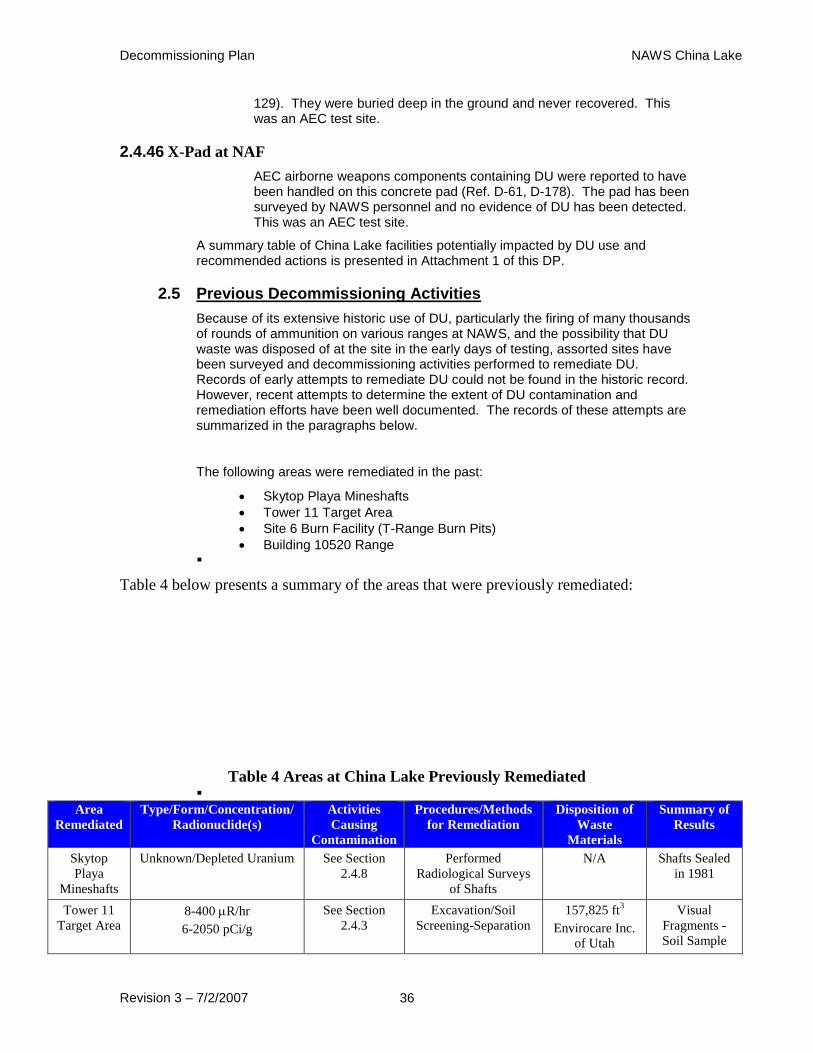
2.5 Previous Decommissioning Activities
Because of its extensive historic use of DU, particularly the firing of many thousands of rounds of ammunition on various ranges at NAWS, and the possibility that DU waste was disposed of at the site in the early days of testing, assorted sites have been surveyed and decommissioning activities performed to remediate DU. Records of early attempts to remediate DU could not be found in the historic record. However, recent attempts to determine the extent of DU contamination and remediation efforts have been well documented. The records of these attempts are summarized in the paragraphs below.
The following areas were remediated in the past:
Skytop Playa Mineshafts
Tower 11 Target Area
Site 6 Burn Facility (T-Range Burn Pits)
Building 10520 Range
Table 4 below presents a summary of the areas that were previously remediated:
Table 4 Areas at China Lake Previously Remediated
Area
Remediated
Type/Form/Concentration/
Radionuclide(s)
Activities
Causing
Contamination
Procedures/Methods
for Remediation
Disposition of
Waste
Materials
Summary of
Results
Skytop
Playa
Mineshafts
Unknown/Depleted Uranium See Section
2.4.8
Performed
Radiological Surveys
of Shafts
N/A Shafts Sealed
in 1981
Tower 11
Target Area 8-400 R/hr
6-2050 pCi/g
See Section
2.4.3
Excavation/Soil
Screening-Separation
157,825 ft3
Envirocare Inc.
of Utah
Visual
Fragments -
Soil Sample

Decommissioning Plan NAWS China Lake
Revision 3 – 7/2/2007 37
Depleted Uranium Results < 35
pCi/g
Site 6 Burn
Facility
Solid/Oxides/Unknown/Depl
eted Uranium
See Section
2.4.7
Survey and Sampling None Back ground
concentrations
Building
10520
Range
Solid/Oxides/Unknown/
Depleted Uranium
See Section
2.4.6
Excavation/Demolition Hanford, WA RASO
Approved Free
Release of
Area in 1996
2.5.1 Skytop Playa Mineshafts
In the early days (circa 1962) of using DU at China Lake, the AEC approved on-site waste disposal for small quantities of DU that had been used in propellant burning tests. Disposal of waste in abandoned mineshafts was considered a reasonable disposal option at the time. There are many abandoned mine shafts on the North Range that could have been used for waste disposal, but no information was found that confirmed that DU waste was actually discarded into any of these shafts. Beginning in January 1981, site personnel investigated the possibility that mine shafts had been used for waste disposal. Background radiation levels were determined from a mine south of Ridgecrest. Dosimeters and survey instruments were used to survey abandoned shafts in the CT-4 area and near Skytop. No elevated radiation levels were detected in any of the surveyed shafts. Two shafts approximately three miles northeast of Skytop were considered likely locations for any potential waste disposal. Personnel entered theses shafts to perform visual inspections in February 1981. One shaft was approximately 35 feet deep and the other approximately 100 feet deep. These entries detected no evidence of disposal of either radioactive or hazardous waste in the shafts. In May 1981, the shafts were sealed with materials originally removed from the shafts (Ref. D-82, D-83, D-84, D-85, D-87, D-91, D-92).
2.5.2 Tower 11 Target Area
In July 1990, AWC, a subsidiary of the Lockheed Corporation, was contracted to survey the target area and catch box at Tower 11 to determine the extent of DU contamination from the testing of 120 mm rounds at this site. Due to the large presence of bare and nearly bare rock around the target area, the soil depth in this area is often limited to less than six inches. Lockheed Environmental Systems and Technologies Company was contracted to remediate the target site. During the subsequent technically complex remediation action by Lockheed and Alliant Tech Systems from December 1991 through November 1993, the target catch box was removed, approximately 5.8 acres of the target area (Ref. D-134) and a contractor’s equipment storage area were decontaminated, and final status surveys conducted. Approximately 4700 cubic yards of contaminated soil were processed by Lockheed (Ref. D-134). The Lockheed Truclean system used in the remediation activities was decontaminated and decommissioned from September through December 1996 (Ref. D-132, D-134, D-136, D-137, D-173).
In August and November 1993, Lockheed sampled the soil following the remediation of the target area at Tower 11. The protocol for the sampling

Decommissioning Plan NAWS China Lake
Revision 3 – 7/2/2007 38
was to divide the area into ten by ten meter grids, obtain soil samples from five locations in each sampling grid (one in the center and four equidistant from the corners and center of the grid—resembling the dots on the five side of a die), thoroughly mixing the samples to achieve homogeneity, measuring 500 grams of the composite samples for counting, and counting the 500 gram samples in a multi-channel analyzer equipped with a three by three inch NaI detector. A total of 426 samples were obtained and counted in this manner.
The criterion for release of the site was 35 pCi/g. The activity range of the analyzed samples was <1 pCi/g to 31 pCi/g, indicating the remediation was successful in reducing residual DU contamination to less than the release level for the target area (Ref. D-137).
Following cleanup of the Lockheed equipment storage area southeast of the Tower 11 range, the same sampling and counting protocol described above was used to ensure the area was properly remediated. In September 1996, 88 samples were obtained and counted from ten by ten meter grids in this area. The counting results ranged from <1 pCi/g to 3 pCi/g. These results also indicated the remediation activities were successful in reducing soil contamination levels below the 35 pCi/g release criterion (Ref. D-136). It is prudent to discuss, that fragments can still be visually identified. Confirmatory sampling by NAVSEADET RASO indicated it was still possible to obtain results above the release criterion in single samples.
Two structures from the remediation effort, an office trailer and a horizontal tank, remain at the old target area. There are no plans to remove these structures.
2.5.3 Site 6 Burn Facility (T-Range Burn Pits)
Six burn pits or trenches are identified at Site 6 (Ref). These pits had been used to dispose of hazardous and other waste by incineration and burial. The wastes included ferrous and non-ferrous metals. The Navy worked with appropriate state and federal environmental protection agencies to determine the proper remediation process for these pits. In 1998, 19 grab samples of soil and ash were collected and analyzed for potential hazardous waste content. Isotopic uranium was included in the analysis. While radionuclide activity was not greater than background, the sampling design was not adequate to support a definitive decision. In 2000, Navy contracted Tetra Tech EM, Inc. (TtEMI) to do a removal site evaluation (RSE) for the six pits. TtEMI developed a sampling and analysis plan to provide statistically meaningful data for the RSE. Sampling included surface, geophysical surveys and trenching, and subsurface soil analyses. Global positioning systems (GPS) were used to locate the pits/trenches and survey/sample locations with precision. No DU in excess of the natural background levels for uranium, approximately 3 parts per million (ppm) (Ref. D-78), in the area was detected (Ref. D-142, D-143, D-144, D-145, D-146). A CERCLA Record of Decision (ROD) for this site was signed by the Navy and DTSC in July 2006 and by the RWQCB in September 2006. The selected remedy is to consolidate waste in the existing trenches and cover all trenches with an evapotranspiration landfill cap. This will consist of up to four feet of soil, which will prevent surface water from infiltrating through the waste.
Table 5 below presents a summary of the soil sample analysis:

Decommissioning Plan NAWS China Lake
Revision 3 – 7/2/2007 39
Table 5 Site 6 Soil Sample Summary
Site 6 Data
In pCi/g
Background Area Data
In pCi/g
Mean
(Average)
Standard
Deviation
Maximum Mean
(Average)
Standard
Deviation
Maximum
Th-228 0.84 0.26 1.32 1.06 0.57 4.18
Th-230 0.74 0.33 1.65 1.35 0.54 3.36
Th-232 0.77 0.28 1.33 1.14 0.63 4.02
U-234 0.63 0.29 1.46 1.72 1.20 9.09
U-235 0.03 0.03 0.12 0.09 0.19 0.73
U-238 0.58 0.29 1.40 0.92 0.43 3.19
2.5.4 Building 10520 Range (known in the historical record as Building 52)
In June 1991, the sand and soil used in the catch box to capture the approximately 3,000 25 mm rounds fired on this range were removed and disposed of as contaminated waste by Allied Technology Group (ATG). ATG decontaminated and surveyed the catch box, concrete pad in front of the catch box, the concrete lined drainage ditch, and the soil behind the back plate from July through November 1992. Soil was removed from behind the catch box and parts of the concrete lined drainage ditch and from the area where the concrete drain discharged to the ground. All contaminated soil was disposed of as low-level radioactive waste. Nine soil samples were taken behind the catch box rear plate and a total of sixteen soil samples were taken at eight locations in the drainage ditch area at the surface and at different depths. The ATG final survey report was submitted to the Navy’s Radiological Affairs Support Office (RASO) in March 1993. RASO commented on various issues that were subsequently clarified by additional reports and surveys. NAWS personnel conducted additional surveys of the catch box and concrete pad, which resulted in additional removal of concrete, and took 23 confirmatory soil samples from selected areas around the gun range that included areas remediated by ATG (e.g., the catch box and drainage ditch). Additional soil was removed from a small area on the floor of the catch box (Ref. D-154).
RASO approved the free release of the area based on a release criterion of less than 25 millirem per year (mrem/y) to the maximum exposed individual was issued on 8 July 1996 (Ref. D-154).
2.6 Spills
No record of DU spills at NAWS was found in the historic documents reviewed. There was a small fire involving approximately 70 grams of Teflon
® coated DU on 29
October 1965 on the dock at Building 10632 (then referred to as the Building 63B dock). The fire was extinguished and follow-up surveys indicated no spread of DU contamination. There was no property damage from the fire.

Decommissioning Plan NAWS China Lake
Revision 3 – 7/2/2007 40
3.0 FACILITY DESCRIPTION
Naval Air Weapons Station China Lake (NAWS) is a 1.1 million acre (1735
square mile) military reservation in the upper Mojave Desert of south central
California. It is approximately 150 miles northeast of Los Angeles at the
boundaries of Inyo, Kern and San Bernardino counties. NAWS China Lake
consists of two separate ranges, the North Range and South Range, connected by a
narrow diagonal corridor. The North Range is where most major research,
development and testing facilities are located and the location of all DU research
and testing according to the available record. A map of NAWS is presented in
Figure 15 below. It should be noted that the lakes shown in Figure 14 are the
physical boundaries of the lakes and that the lakes are “dry” lakes.
3.1 Site Location and Description
The North Range is approximately 1100 square miles of high desert land in a roughly rectangular shape about 40 miles long (north-south) by 30 miles wide (east-west). The North Range includes the relatively flat Indian Wells Valley, where the station’s namesake dry China Lake is located, the Salt Wells Valley to the east of Indian Wells Valley, and surrounding mountains, mesas and canyons. The North Range abuts the northern city limit of Ridgecrest, the major population center in the area, and extends to the Sierra Nevada Mountains in the west and northwest, the Coso Range in the north, and to the Argus Range in the east. Elevation varies from approximately 2,100 feet to more than 8,900 feet above sea level. Weapons and DU munitions were tested on ranges in the southern end of the North Range, primarily on the G-6, K-2, Tower 11 and Kennedy Stands ranges, all of which lie 10 to 15 miles north of Ridgecrest, and the Station administrative and laboratory areas, which are at the extreme south of the North Range.
The South Range, or Randsburg Wash/Mojave B complex, comprises the remainder of NAWS. The South Range is primarily used for electronic warfare testing and development. This range will not be addressed in this DP as there is no evidence of the use of DU at the South Range.

Decommissioning Plan NAWS China Lake
Revision 3 – 7/2/2007 41
Figure 15 General Map of NAWS China Lake North Range Showing DU Impacted
Sites (Ref. D-149)

Decommissioning Plan NAWS China Lake
Revision 3 – 7/2/2007 42
3.2 Population Distribution
The region surrounding NAWS China Lake is sparsely populated. The communities in closest proximity to NAWS, Ridgecrest, China Lake Acres and Inyokern, have populations of 25,854 (2004 census estimate), 1,761 (2000 census) and 984 (2000 census), respectively. Ridgecrest and China Lake Acres are immediately south of and abut the southern boundary of NAWS North Range. Inyokern is immediately outside the southwest corner of NAWS North Range. To the east of the Station beyond the Argus Range lies the Searles Valley that is dominated by mineral extraction operations on the dry bed, or playa, of Searles Lake. The major population center in the Searles Valley is the town of Trona where the chemical products of Searles Lake are processed. As of the 2000 census, the population of the Searles Valley was 1885. Figure 16 presents a map of NAWS China Lake and the surrounding areas.
Figure 16 General Map of NAWS China Lake and Surrounding Areas
NAWS has a workday population of approximately 4400. This includes military staff, civilian employees, and family members of the military staff.
The populations of the three counties in which NAWS is located are (as of the 2000 census): Inyo 17,945; Kern 661,645; San Bernardino 1,709,434. The majority of these inhabitants live more than 50 miles from the bounds of NAWS North Range.
Sixteen public and private schools and a community college are located in the two communities immediately adjacent to NAWS, Inyokern and Ridgecrest (Ref. W-21). The names, addresses, grade range and student populations of these schools are summarized in Table 6 below.

Decommissioning Plan NAWS China Lake
Revision 3 – 7/2/2007 43
Table 6 Schools in the Vicinity of NAWS China Lake
School Name
Address and Telephone
Number
Grade Range
Number
of
Students
Hours
Of
Operation
Reference
Adventist
Christian
School
555 Las Flores St.
Ridgecrest, CA 93555
760-375-8673
01-08
21
0800-1515
W-21
Burroughs
High
School
500 E. French St.
Ridgecrest, CA 93555
760-375-4476
09-12
1750
0630-1630
W-02
Faller
Elementary
School
1500 W. Upjohn St.
Ridgecrest, CA 93555
760-375-5081
K-05
465
0700-1600
W-07
Gateway Elementary
School
501 S. Gateway
Ridgecrest, CA 93555
760-384-3228
K-05
490
0600-1600
W-08
Heritage
Montessori
Pre-School
934 Heritage
Ridgecrest, CA 93555
760-446-7459
Pre-school-K
80
0645-1730
W-21
Immanuel
Christian
School
201 Graf St.
Ridgecrest, CA 93555
760-446-6114
Pre-school-12
165
0730-1600
W-21
Inyokern Elementary
School
P.O. Box 1597
Inyokern, CA 93527
760-377-4336
K-05
152
0730-1600
W-10
Las Flores
Elementary
School
720 W. Las Flores St.
Ridgecrest, CA 93555
760-375-8431
K-05
460
0700-1600
W-11
Mesquite Continuation
High School
140 W. Drummond St.
Ridgecrest, CA 93555
760-446-4561
09-12
156
0700-1600
W-12
Monroe (James)
Middle
School
340 W. Church St.
Ridgecrest, CA 93555
760-375-1301
06-08
607
0700-1600
W-13
Murray
Middle
School
921 E. Inyokern Rd.
Ridgecrest, CA 93555
760-446-5525
06-08
754
0700-1630
W-14
Pierce
Elementary
School
674 N. Gold Canyon
Ridgecrest, CA 93555
760-375-5016
K-05
486
0730-1630
W-16
Pilgrim
Christian
School
1305 W. Ridgecrest Blvd.
Ridgecrest, CA 93555
760-375-1528
K-12
25
0825-1500
W-21
Richmond Elementary
School
1206 Kearsarge St.
Ridgecrest, CA 93555
760-446-2531
K-05+
Special
Education
440
0730-1600
W-18
Ridgecrest
Charter
School
325 S. Downs
Ridgecrest, CA 93555
760-375-1010
K-08
245
0730-1600
W-19
Saint
Ann
School
446 West Church St.
Ridgecrest, CA 93555
760-375-4713
K-08
135
0700-1415
W-21
Cerro Coso
Community
3000 College Heights Blvd.
Ridgecrest, CA 93555
Two
Year
2000
0745-2100
W-21

Decommissioning Plan NAWS China Lake
Revision 3 – 7/2/2007 44
College 760-384-6100 Curriculum
3.3 Current and Future Land Use
NAWS is a principal weapons research, development, testing and evaluation (RDT&E) facility for the U. S. Navy and the Department of Defense (DoD). It has been in continuous operation since its establishment in November 1943. It represents one-third of the Navy’s total landholding and is expected to retain its weapons development and testing functions into the future.
The primary uses of the land surrounding NAWS include residential and commercial development, light agriculture, and mining. These activities have existed for the past century and a half and are expected to persist into the foreseeable future.
The city of Ridgecrest has experienced fluctuations in its population and economy relative to changes in operations and employment at NAWS. Land use in and around Ridgecrest will continue to reflect infrastructure changes necessary to support NAWS, including construction of housing, roads, commercial and retail businesses, schools, and public utilities.
3.4 Ambient Air Quality
The ambient air quality of the entire State of California is in attainment for
each of the five “criteria” pollutants as described by the National Ambient Air Quality
Standards (NAAQS) (MDEQ 2000). In addition to the ambient air quality standards for
so called criteria pollutants, the federal government has categorically designated 156
national parks and wilderness areas as Class 1 areas (Figure 17) subject to enhanced air
quality protection guidelines. The NAWS Site is not located in a Class 1 Area as
designated by the Federal government. The closest Class 1 Area to the site is the Dome
Land Wilderness Area, located 23 miles to the west in California. The first downwind
Class 1 Area is Zion National Park located approximately 250 miles to the northeast in
the State of Utah.

Decommissioning Plan NAWS China Lake
Revision 3 – 7/2/2007 45
Figure 17 EPA Class 1 Areas
3.5 Meteorology and Climatology
The meteorology and climatology information below was extracted from reference W-28. Detailed meteorology and climatology information for the years 1960 to 1993, which covers the years of DU use at NAWS covered by this DP, is provided in reference W-26.
NAWS is located in an arid desert environment. The air is clear most of the year and normal precipitation varies from three to six inches annually in the Indian Wells Valley. Precipitation in the Argus Range to the east is up to ten inches per year and can exceed ten inches per year in the Sierra Nevada Mountains to the west. Precipitation is usually in the form of rain, except for the higher mountain elevations where it occasionally snows. Visibility is generally greater than 50 miles. The mean annual temperature is 63.7
◦F, and the temperature ranges from 0 to 118
◦F. The
mean daily minimum and maximum temperatures are 47.4◦F and 80.1
◦F,
respectively.

Decommissioning Plan NAWS China Lake
Revision 3 – 7/2/2007 46
Summer is characterized by hot, dry days with cool nights. Afternoon temperatures rise to 100
◦F or higher about 66 days a year and drop into the 60s at night. The wind
is generally light and variable, but with afternoon heating, a south-southwest wind can begin to blow and last into the evening hours. Summer precipitation from thunderstorms usually occurs during August and September.
Winters are cool with nighttime temperatures dropping to 32◦F or less for about 77
days a year with warming into the 50s during the day. Precipitation is at its maximum from October through March with February being the wettest month. Normally, frontal systems move rapidly through the area and can be expected on an average of three a month. Table 7 provides a summary of the climate.
Table 7 Climate Summary
Period Min Temp (◦F) Mean Temp
(◦F) Max Temp (◦F) Rain (inches)
Mean %
Humidity
January 0 43 77 0.71 53
April 33 61 102 0.15 39
July 50 86 118 0.23 27
October 21 65 103 0.17 36
Annual Average
48 64 80 4.28 39
Prevailing winds are from the southwest at an average wind speed of 6.6 mph. Strong surface winds occur in late winter and spring as cold fronts move rapidly through the area. Wind speeds in excess of 25 mph occur throughout the year with wind speeds greater than 50 mph common between October and June.
NOTE ON SECTIONS 3.6 THROUGH 3.8: Detailed information about the geology
and hydrogeology of NAWS China Lake is available in the Tetra Tech EM Inc. base
wide hydrogeology characterization study which was performed beginning in 1999
and reported in 2002 (Ref. D-181). Geology and hydrology are also discussed in
extensive detail in the 2003 Argonne National Laboratory Depleted Uranium
Characterization study (Ref. D-183).
3.6 Geology and Seismology
The NAWS China Lake base is located in the upper Mojave Desert of California. The primary features of the site considered in this DP are in the Indian Wells and Salt Wells Valleys. These valleys are in the southwestern corner of the Great Basin section of the Basin and Range Physiographic province. This province is characterized by isolated, north-trending mountain ranges separated by desert basins. The Indian Wells Valley, where most of NAWS target ranges are located, lies adjacent to and west of the Salt Wells Valley, is bordered on the west by the southern Sierra Nevada, on the east by the Argus Range, on the north by the Coso Range, and on the south by the El Paso Mountains and the Spangler Hills. The Salt

Decommissioning Plan NAWS China Lake
Revision 3 – 7/2/2007 47
Wells Valley is approximately eight miles wide and is bounded to the north by low, rocky hills that comprise the southernmost end of the Argus range.
Indian Wells Valley lies north of the Garlock Fault and east of the Sierra Nevada Frontal Fault. NAWS and the surrounding areas are seismically active (Ref. W-01, W-17, D-183), with a history of large to moderate earthquakes and frequent microseismic activity. The Coso Mountains have a potential for large-magnitude (7.0 to 7.5 on the Richter Scale) earthquakes and an active northwest trending fault is projected into the Salt Wells Valley. Combined seismic-refraction, gravity, aeromagnetic, and geologic studies define a large, structurally depressed block of pre-Tertiary rock which has been folded and warped, and is bounded by steeply dipping faults.
Granite, granodiorite and metamorphic rocks form the basement of fault-controlled structural basins in the Indian Wells and Salt Wells Valleys. These basins are filled with water-bearing deposits of Quaternary age.
A geologic concern for NAWS China Lake is the amount of naturally occurring uranium (U) existing in the native rock, sand, and soil. In a 1981 study, the head of the base’s Geothermal Utilization Division estimated the U in the rock and the top six inches of soil at NAWS (then the Naval Weapons Center) (Ref. D-78, D-134). There are no significant concentrated deposits of naturally occurring U on the NAWS site, but 3 parts per million (ppm) is a reasonable estimate of the general dispersion of U in both rocks and soil. Each 50 foot cube of rock, with a density of 2.7 and 3 ppm U, would contain about 63 pounds of uranium, primarily as a “rather mobile coating on mineral grains for the upper portions of the hillsides” (Ref. D-78) . In the top six inches of soil, the probable U content per square mile would be 4,181 pounds, using 3 ppm of naturally occurring U.
3.7 Surface Water Hydrology
Little surface water flow occurs in the Indian Wells Valley. Most precipitation is given up to evaporation or is used by the valley’s vegetation. Most surface water runoff from the surrounding mountains infiltrates into the groundwater aquifers along the mountain fronts. Occasionally, surface water runoff from the El Paso Mountains reaches the valley floor via four ephemeral streams: El Paso Wash, Little Dixie Wash, Ridgecrest Wash and Bowman Wash. These and other smaller washes sometimes discharge water into China Lake, Mirror Lake and Satellite Lake which are primarily “dry” lake beds.
Numerous springs exist in the Argus Range and a few freshwater springs are located along the western edge of the Coso Range, primarily at elevations higher than 6,000 feet above mean sea level (msl). No naturally occurring perennial streams or lakes are located on the valley floor, but 49 springs or seeps have been identified within the China Lake complex. Two of these seeps are environmentally sensitive because they are the habitat of the Mojave tui chub, an endangered fish species. These seeps are located on the edge of the China Lake playa and are connected by a ditch. Groundwater flow from the south and southwest supplies water to these two seeps and their connecting ditch; the major portion of the water supplied to this drainage area is thought to originate from the Ridgecrest sewage treatment ponds. These seeps are located approximately four miles from the Kennedy Stands area.
3.8 Groundwater Hydrology
Human activities in the Indian Wells Valley, which includes that part of NAWS considered in this decommissioning plan, the town of Inyokern and the city of
Decommissioning Plan NAWS China Lake
Revision 3 – 7/2/2007 48
Ridgecrest and their environs, are dependent on extraction of groundwater from the aquifer underlying the valley. All groundwater in the valley has as its source precipitation in the mountains surrounding the valley. The water does not move in a stream or channel, but percolates through pore spaces in water-bearing formations from areas of replenishment to points of discharge. There is no evidence of any underground source or movement of water from outside the drainage area. There is a small outflow of groundwater from the Indian Wells Valley to the Salt Wells Valley through a narrow channel, which is the most recent outlet from the Pleistocene China Lake.
A base-wide hydrogeologic characterization study conducted by China Lake
identified three hydrogeologic zones in the Indian Wells Valley; shallow, intermediate,
and deep (Ref. D-181). The shallow hydrogeologic zone (SHZ) is composed of alluvium
and playa deposits. The maximum thickness of this zone is approximately 200 feet on the
western side of the China Lake Complex. This is underlain by the intermediate
hydrogeologic zone (IHZ) which is composed primarily of low-permeability lacustrine
silts and clays, interbedded with sand stringers. The thickness can reach over 1000 feet
thick near the center of the Indian Wells Valley. The deep hydrogeologic zone (DHZ) is
the only zone present in the southern and western portions of the basin, and underlies the
IHZ in the central, northern and eastern portions. The DHZ consists primarily of course
sand and gravel, with some discrete clay layers. The DHZ is the largest zone, reaching
thicknesses of several thousand feet.
Recharge to the DHZ occurs as groundwater underflow from permeable materials
in canyons of the Sierra Nevada, Coso and Argus mountain ranges and as deep
percolation from stream flow from Rose Valley and Freeman Gulch. The effects of the
Sierra Nevada on groundwater makeup are considered to be greater than those from the
Coso and Argus ranges because more moisture is in the air passing over the Sierra
Nevada resulting in greater precipitation in that range.
In the Indian Wells Valley groundwater discharge occurs naturally from
evapotranspiration and underflow into Salt Wells Valley and artificially by pumping from
wells. Most wells in the valley penetrate into the DHZ only 50 to 400 feet, but some
production wells are close to 1000 feet deep. The depth to water of most of these wells is
between 100 and 200 feet. Most of the main water body in the DHZ is unconfined.
However, in the eastern part of the valley the DHZ is covered by the IHZ and SHZ,
creating confined aquifer conditions.
The IHZ occupies the central part of the valley. Its approximate boundaries are
the Inyo County line to the north, an east-west line approximately 2.5 miles south of the
southern boundary of NAWS North Range to the south, the Argus fault zone on the east
and a probable groundwater barrier about two miles south of Inyokern in the southwest.
The bottom of the water body is approximately 1,000 feet below the surface beneath most
of the central area.
The SHZ lies above the IHZ principally around the China Lake playa and vicinity.
The base of the shallow water body is poorly defined, but is roughly between 50 and 150
feet below ground surface. No production wells exist in the SHZ Water pumped from
this zone is of poor quality because of the dissolved chemicals it contains.
Since 1944, groundwater in the valley has been used primarily by NAWS and the
Indian Wells Valley Water District, which serves the public living in the Ridgecrest area.
Decommissioning Plan NAWS China Lake
Revision 3 – 7/2/2007 49
Current estimates are that approximately 22,000 acre-feet (one acre-foot equals the
amount of water that would cover one acre to a depth of one foot or 43,560 ft3) per year
are currently withdrawn by groundwater pumping in the valley. Most of the water supply
wells are located in the Ridgecrest, Intermediate Well Field and Inyokern areas.
Numerous private wells also are located in the valley. Private uses of groundwater
include large-scale irrigation. One farming company’s use has averaged about 7,500
acre-feet per year for the past few years. Current estimates indicate groundwater makeup
is approximately 11,000 acre-feet per year, or about half the groundwater depletion. The
majority of groundwater production is from the DHZ, with only a few wells in the
Ridgecrest area producing from the IHZ.
3.9 Natural Resources
NAWS is surrounded by largely undeveloped public lands. Most of this property is managed by the U.S. Bureau of Land Management under the California Desert Conservation Act. Some agriculture occurs in the surrounding area and hard rock mining occurs in the surrounding mountains (Ref. D-183). Extensive surface mining of commercially valuable chemicals from the bed of Searles Lake to the east of NAWS is the major exploitation of natural resources in the immediate vicinity of the base.
The groundwater aquifer is the primary natural resource existing and exploited at NAWS. Water is pumped from the aquifer for use at the base and in the adjacent communities. Much of the groundwater from beneath Kern County is owned by and pumped to the city of Los Angeles.
3.10 Environmentally/Archaeologically Sensitive Areas
NAWS is rich in environmental and archaeological assets. It is home to two endangered species, the desert tortoise and the tui chub, as well as other desert-dwelling wildlife. While no endangered species habitat is known to exist at the sites considered for remediation in this DP, all work planning will be conducted with due consideration for the potential harm to the desert environment. NAWS environmental personnel will be consulted during work planning to ensure that decommissioning activities cause no environmental damage.
In historic times, the Indian Wells Valley area was the province of three Numic peoples: the Koso, Kawaiisu and Chemehuevi. The Chemehuevi and Kawaiisu, southern Paiute groups, occupied the southern portion of the Ridgecrest area, including the southern end of the China Lake complex. The Koso, or Panamint Shoshone, occupied the northern portion of the Indian Wells Valley, including the Coso Mountains, Indian Wells Valley, the Argus Range and Panamint Valley. The Coso Mountains and the Little Lake area formed the Kuhwiji district, an area of approximately 1,000 square miles which contained four villages (Ref. W-06).
The harsh desert environment permitted only sparse populations of these ancient people. Groups moved with the season and in response to the local water and food supply. Obsidian was heavily mined and was used for trade as well as for local uses. Remnants of extensive obsidian mining, covering several miles, have been found in the vicinity of Sugarloaf Mountain in the China Lake complex (Ref. W-06). Native American peoples left artifacts from their lives on the site of NAWS. Thousands of petroglyphs exist on the rocks of the mountainous reaches of NAWS. While no petroglyphs are known to be located on any of the ranges affected by this plan, there are other archaeologically sensitive considerations for planning any
Decommissioning Plan NAWS China Lake
Revision 3 – 7/2/2007 50
remediation actions to support this DP. Evidence of encampments along the shore of the old China Lake is known to exist at the Kennedy Stands site. This evidence includes stone tools and projectile points and remnants of ancient campsites. Entry to these archaeologically sensitive areas is restricted and NAWS personnel responsible for the preservation of these sites will be consulted for approval of any remediation activities which may impact these areas or any other potentially sensitive sites.
4.0 RADIOLOGICAL STATUS OF FACILITY
In March and April 2002, the Argonne National Laboratory conducted both
aerial and ground surveys of locations known to have been impacted by the use of
DU at NAWS in an attempt to characterize DU present at the Kennedy Stands, K-2
Gunnery Range, G-6 Phalanx Range, X-3 Bomb Craters, Building 52 Catch Box,
T-Range Burning Ground, and the CT area (Ref. D-183). These surveys are
described below.
From 25 April until 30 May 2002, New World Technology (NWT) was
contracted to perform characterization surveys for the presence of DU at the G-6
Phalanx Range, K-2 Gunnery Range, and the Kennedy Stands areas and to remove
retrievable DU. Approximately 36 DU rounds and fragments were retrieved during
these surveys (Ref. D-181, D-182). These investigations confirmed that the
evaluated survey designs proved to be cost effective and efficient methods for
conducting surveys. The techniques used were able to detect whole DU penetrators
up to depths of 30 cm (one foot) and fragments of penetrators at or near (within
several inches of) the surface (Refs. D-181, D-182).
4.1 Contaminated Ranges
4.1.1 Aerial Surveys
Using an array of sodium iodide (NaI) detectors slung from the landing skid of a Bell 412 helicopter with associated data acquisition and analysis hardware and software, a total of ten data collection flights were made over the Kennedy Stands, K-2 Gunnery Range, X-3 Bomb Craters, G-6 Phalanx Range, Building 10520 (Building 52) catch box, T-Range Burning Ground, and CT Area from 12 to 17 March 2002. The helicopter flew at an altitude of 50 feet above ground level (agl) and a speed of 60 knots. Using global positioning technology, the survey scans were made over overlapping parallel lanes in each of the areas surveyed. The total survey area flown was more than 14 square miles (mi
2). Survey results were
inconclusive because of the height and speed of the helicopter and the wide variations in the naturally-occurring background radiation levels.
4.1.2 Kennedy Stands
For each detector used during the characterization survey, thirty, one-minute gamma count rates were measured using a 2" by 2" sodium iodide (NaI) gamma scintillation detector system. The area selected to obtain the readings was an area south of the former viewing stands. This area was chosen due to its being located in a non-impacted area and its similar physical, chemical, geological, radiological, and biological characteristics as the areas that were surveyed for the characterization survey effort.
The average background level was approximately 13,500 cpm gamma.
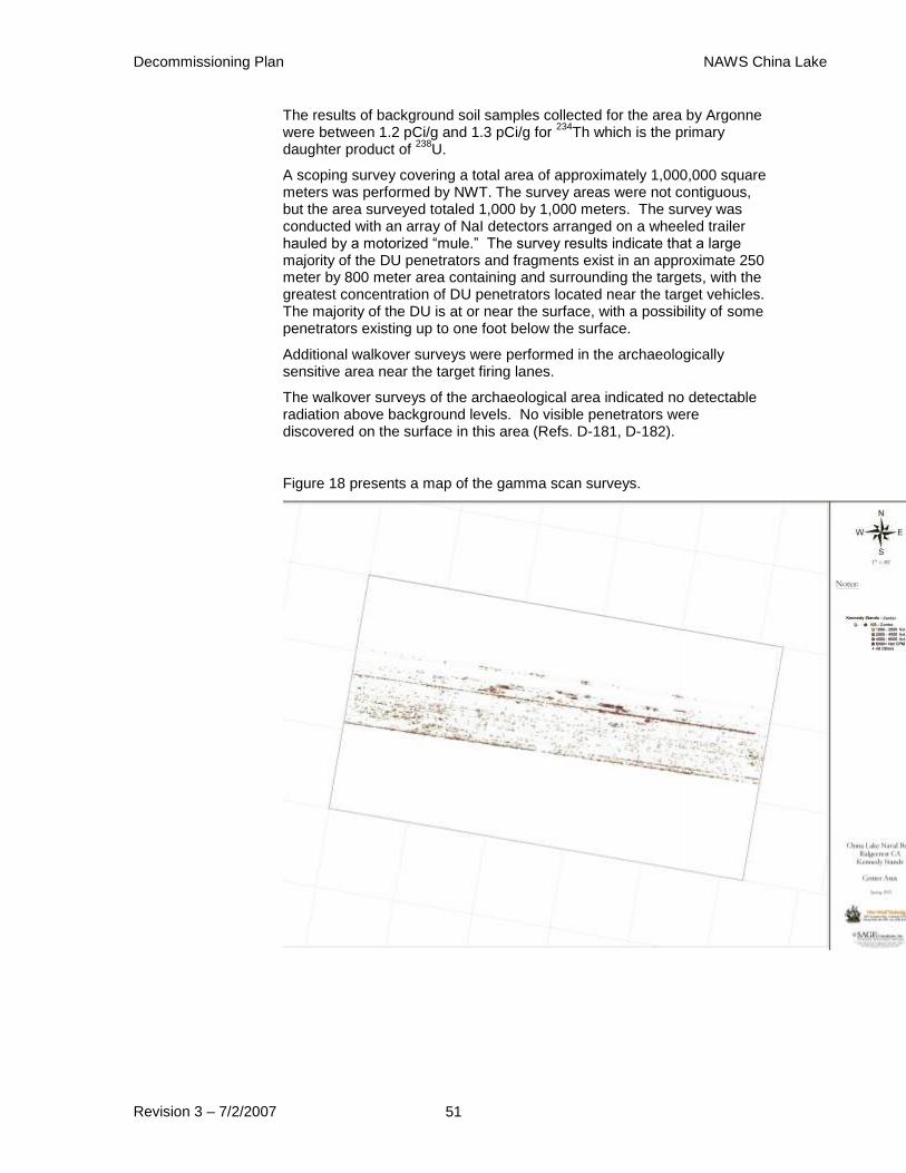
Decommissioning Plan NAWS China Lake
Revision 3 – 7/2/2007 51
The results of background soil samples collected for the area by Argonne were between 1.2 pCi/g and 1.3 pCi/g for
234Th which is the primary
daughter product of 238
U.
A scoping survey covering a total area of approximately 1,000,000 square meters was performed by NWT. The survey areas were not contiguous, but the area surveyed totaled 1,000 by 1,000 meters. The survey was conducted with an array of NaI detectors arranged on a wheeled trailer hauled by a motorized “mule.” The survey results indicate that a large majority of the DU penetrators and fragments exist in an approximate 250 meter by 800 meter area containing and surrounding the targets, with the greatest concentration of DU penetrators located near the target vehicles. The majority of the DU is at or near the surface, with a possibility of some penetrators existing up to one foot below the surface.
Additional walkover surveys were performed in the archaeologically sensitive area near the target firing lanes.
The walkover surveys of the archaeological area indicated no detectable radiation above background levels. No visible penetrators were discovered on the surface in this area (Refs. D-181, D-182).
Figure 18 presents a map of the gamma scan surveys.

Decommissioning Plan NAWS China Lake
Revision 3 – 7/2/2007 52
Figure 18 Kennedy Stands Survey Map
4.1.2.1 Ground (Kiwi) Surveys
Using the same array of NaI detectors that were used on the helicopter, but rigged on a platform hung from the rear of a four wheel drive pickup truck, surveys of the ground between the two rows of targets at the Kennedy Stands and several paths beyond the northern row of target vehicles were performed on 4 and 5 April 2002. The Kiwi collected 15,805 data points at Kennedy Stands and covered an area of approximately 29,000 m
2. The gross-count data ranged from 11,000 to 30,000 cps, with
the majority of the points below 19,000 cps.
The detectors were arrayed 12 inches above the ground surface and the truck drove the survey lanes at five miles per hour or less for maximum detection sensitivity. The Kiwi survey was more sensitive than the airborne survey and indicated concentrations of DU within 15 feet of the target vehicles, the count rates dropping off rapidly beyond this distance (Tank 9).
Figure 19 below presents a map of the results of the KIWI with data points from the Kennedy Stands area overlain on the gross-count results. This figure shows the data collection pattern for the Kiwi at Kennedy Stands.
Figure 19 Kennedy Stands KIWI survey Data Map
The northern row of targets is represented by the areas with no data (the
white areas within the figure). The areas around these targets have elevated gross counts.
The X-and Y-axis values are in feet. This plot also shows elevated gross counts in the
southwestern and southeastern portions of the surveyed area. The elevated DU
concentrations around the targets can be clearly seen. In addition, there is an area of
elevated DU concentration east of the eastern-most target at Kennedy Stands. This is the

Decommissioning Plan NAWS China Lake
Revision 3 – 7/2/2007 53
DU remaining around a target that was present during testing but that was subsequently
removed from Kennedy Stands.
The southern portion of the map shows the locations of the targets on the
southern target line. These targets do not have DU concentrations as high as those on the
northern target line. This result matches field observations, which found significantly
more penetrators and DU fragments around the targets on the northern line and less
visible DU around the targets on the southern line.
The elevated DU net-count data points were associated with all the known
penetrators that were found on the surface at Kennedy Stands during Kiwi data
collection. There are many more readings that suggest isolated penetrators than were
found during field investigations. This is most likely the result of several factors: (1) not
all penetrators were located during field investigation (subsequent investigations by New
World Technologies located and removed numerous penetrators on the surface), (2) some
penetrators are located slightly below the surface and can be detected by the Kiwi, but not
found by visual inspection, and (3) a number of these isolated points are the result of
expected statistical variation in the data.
The southwestern and southeastern corners of the Kennedy Stands gross-
count data both show elevated readings. The readings in the southwestern corner of the
surveyed area are associated with some isolated DU from a target on the southern target
line. However, the gross-count appears to represent much higher DU concentrations than
those that exist in the field. The southeastern corner of the Kennedy Stands gross-count
results has elevated gross-count readings that are not associated with any indication of
DU contamination in the DU net-count plots. These elevated gross-count readings could
be the result of geologic material changes, rather than DU contamination.
The Kiwi results show that continuous areas of DU contamination at
Kennedy Stands are restricted to the areas immediately around the targets. Outside of
these areas, individual penetrators may be found, but there are no large areas of
contamination.
4.1.2.2 Distribution of Fired Depleted Uranium Rounds
NAWC China Lake records identify a total of 3391 25 mm rounds fired at Kennedy Stands target area. Reports and memoranda for three major tests identified the number of rounds fired at each target and the target position (Refs. D-69, D-70, D-93, D-125). The results are summarized in Table 8 below. The target positions were identified by firing lanes 1 through 4. Memoranda and surveys indicate that the location of the T-62 tank, identified as Lane 1, has not changed since the original test in 1980. The data is presented to correspond to Figure 19. The highest readings in Figure 19 correspond to the location of the T-62 tank.
Table 8 Kennedy Stands Firing Summary Table
Test Date Left of
Lane 4
Lane 4
Target
Lane 3
Target
Lane 2
Target
Lane 1
Target*
Lane 0
Target
Dec 1980 M-47 M-47 M-47 M-47 T-62

Decommissioning Plan NAWS China Lake
Revision 3 – 7/2/2007 54
568 109 99 92 380
May
1981**
M-59
83
M-41
77
M-47
285
184 329
Mar
1989***
M-47
129
M-47
219
M-47
177
153 M-47
184
Total 568 321 680 453 862 184
*Assumes that the position of the T-62 tank has never changed.
**Arbitrary assignment of rounds to 2 known M-47 targets
***Arbitrary assignment of rounds to M-47 tanks and assumes M-47 tanks
are in their current positions
Thus, a total 3068 rounds or 90.5% of all DU fired at Kennedy Stands were fired at the northern line of targets in their current location (less the two western most targets) and extending north of the targets. Reports of the testing identified test firing conditions: an air speed of 500 knots indicated air speed (575 miles per hour), an initial altitude of 300 feet and a final altitude of 200 feet above the ground, a five degree down angle, and an open fire to cease fire line of 1000 feet. The pilots at China Lake made several practice runs with non-DU ammunition before test firing DU that should result in a controlled dispersion of DU. The Harrier jet fired 0.5 and 1.0 second bursts (in all but one run). At an aircraft speed of 575 miles per hour, the jet will travel 850 feet in 1.0 second in horizontal flight, the approximate length of a burst. The initial and final altitudes confirm that the jet remained in a nose down attitude (non-horizontal flight). Accordingly for planning purposes, the northern boundary for survey of the firing lanes will be established 500 feet beyond the northern line of targets.
4.1.2.3 Investigation of DU Mobility in Soil (Kennedy Stands)
In 2003, the Navy and the University of Nevada, Las Vegas
(UNLV) conducted investigations into the extent of vertical and
lateral transport of uranium from DU penetrators at the Kennedy
Stands and G-6 ranges. These studies were reported and analyzed
by Argonne National Laboratory in 2003 (Ref. D-149, D-172). This
study also investigated the concentrations of DU found near T-62
tank. A large (~ 860 rounds) number of DU penetrators were fired
at this one tank.
The studies concluded that the mobility of DU from penetrators and
fragments was very limited. Most DU remained within four inches
vertically and 12 inches horizontally of individual penetrators.
There is also a dense clay-like material beneath surface sands, which
is largely impermeable to the transport of solid DU materials. This
layer of clay prevents the ready transport of DU to the groundwater
underlying NAWS. (Ref. D-149)

Decommissioning Plan NAWS China Lake
Revision 3 – 7/2/2007 55
The Kennedy Stands soils exhibit a relatively high clay fraction,
which likely strongly retards downward transport of uranium, while
uranium precipitation mechanisms at this site further limit uranium
transport by groundwater. Surface processes at the Kennedy Stands
area are dominated by eolian (wind-driven) erosion/deposition of
medium to fine sands. The majority of uranium activity in surface
and subsurface soils at this location is associated with larger sand-
and gravel-sized particles, which are not readily transported by
eolian processes. Thus, the movement of DU at this location via
surface processes is expected to be minor.
The lowest uranium distribution coefficient (Kd) value, 5.5 ± 3.3 mL
g-1
was noted for the soil horizon consisting of wind blown sand (1-
25 centimeters in depth) , which had no clay. The higher Kd values
were 110 to 150 ± 70 mL g-1
at depths between 2 and 60 centimeters.
There were positive correlations between the uranium distribution
coefficient and both soil solution equilibrium pH and soil clay
content. Soil clay content (and therefore cation exchange capacity)
is the predominate factor controlling uranium sorption onto
Kennedy Stands soils.
The distribution coefficients (Kd) were determined under saturation
conditions, and therefore, are only valid under those conditions. At
Kennedy Stands, the probability of soil saturation depends upon the
soil horizon. The most likely occurrence of saturation is the surface
layer in the lake bed where a seasonal perched water table may form
due to the limited permeability of the clay horizons. Lack of
saturation, and therefore, lack of equilibrium conditions will cause
slower vertical transport of uranium than the normal distribution
coefficient model predicts.
Surface and subsurface soil samples were also collected during this
effort. Surface soil sample results ranged between a minimum of
2.14 pCi/g to 2,980 pCi/g with an average concentration of ~ 106
pCi/g. Subsurface (below 15 cm) soil sample results ranged
between 1.84 pCi/g to 13.5 pCi/g.
4.1.3 K-2 Gunnery Range
Eleven background samples were collected and analyzed by gamma spectroscopy analysis. No
238U or associated decay progeny were
detected in any of the samples above the required reporting limit of 5 pCi/g. The results of the background sample analysis are provided in Table 9 below.
In 1996, IT Corporation was contracted by the Navy to perform a comprehensive survey
for DU activity remaining on the K-2 Range. However, the survey only covered the
western two-thirds of the range. The eastern one-third of the range, ending in the main
berm, was not surveyed because of the risk from suspected high explosive shells.
Decommissioning Plan NAWS China Lake
Revision 3 – 7/2/2007 56
Beginning in June 1996, and prior to the sampling and analysis for DU, a radiological walkover scoping survey using a large area scintillation detector was conducted and used in establishing a grid system for subsequent sampling. Based on this scoping survey, the site was classified into three areas based on observed activity: Class 1 for areas of highest activity, Class 2 for intermediate activity, and Class 3 for lowest activity.
A characterization survey was conducted in December 1998 that included a second walkover survey and soil sampling. The Class 1, 2 and 3 areas received survey coverage of 100%, 25% and 10%, respectively. The second survey identified 26 additional Class 1 grids, extending the original scope approximately 100 meters beyond the original scoping survey’s northeast boundary. The survey grids were ten by ten meters.
After the second survey was completed, a sampling plan was developed based on a systematic and problematic strategy. For systematic sampling of Class 1 and 2 grids, four samples were collected equidistant from the center and four corners of each grid. The four samples collected from Class 2 grids were composited and counted. The Class 1 samples were counted individually and additional problematic samples were collected from areas of elevated activity. For Class 3 grids, one sample was collected from each grid, biased toward the highest radiation reading in the grid. Class 3 samples were composited from ten grids for analysis.
Samples from all grids were collected at depths up to six inches (15 cm). Additional samples were collected in Class 1 grids at six to twelve inches and twelve to 18 inches bgs based on field measurements of radioactivity at the sample location.
Twenty (20), ten-to-one composite and two ten-to-one field duplicate samples were collected from Class 3 areas. One hundred and nineteen (119), four-to-one composite and 13 field duplicate samples were obtained from Class 2 areas. Three hundred and eighty five (385) discrete and 40 field duplicate samples were obtained from Class 1 areas. Ten background samples were obtained from areas adjacent to, but not impacted by, the firing range.
Samples were analyzed for explosive residue as well as radioactivity. Samples exceeding 35 pCi/g for uranium and 5 pCi/g for radium were considered impacted. The final walkover survey identified 36 grids with elevated radiation levels due to the presence of depleted uranium, and field sampling confirmed these measurements. None of the samples collected indicated radium levels greater than 5 pCi/g.
The surface soil exceeded the DCGL in 31 Class 1 grids, the soil 6-12 inches bgs exceeded the DCGL in 12 Class 1 grids, and the soil exceeded the DCGL at 12-18 inches bgs in grids 44, 204, 245, and 284.
The report estimated that 390 cubic yards (yd3) would have to be removed
to remediate the site (Ref. D-184).
Figure 20 presents a map of the final reference coordinate system with the final grid classifications indicated. Figure 21 and 22 present maps of the soil sample analysis results. Table 10 presents a summary of the soil sample results greater than the DCGL.
Table 9 K-2 Gunnery Range Background Reference Area Sample Summary Table
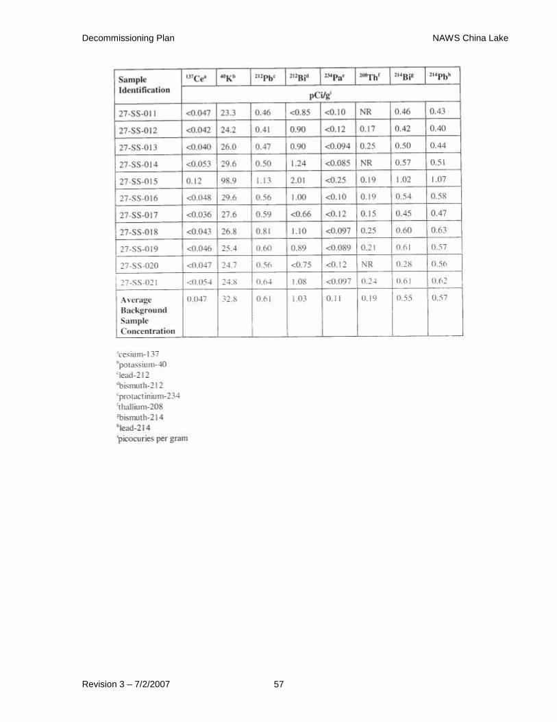
Decommissioning Plan NAWS China Lake
Revision 3 – 7/2/2007 57
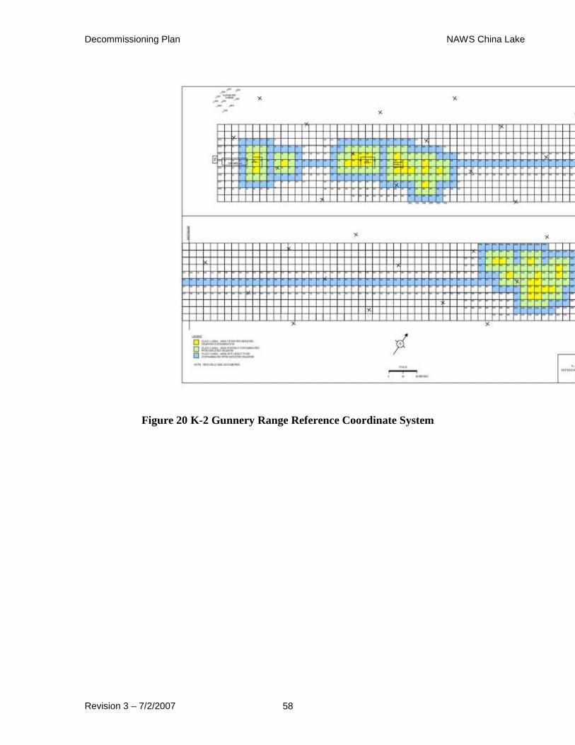
Decommissioning Plan NAWS China Lake
Revision 3 – 7/2/2007 58
Figure 20 K-2 Gunnery Range Reference Coordinate System
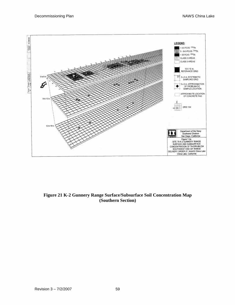
Decommissioning Plan NAWS China Lake
Revision 3 – 7/2/2007 59
Figure 21 K-2 Gunnery Range Surface/Subsurface Soil Concentration Map
(Southern Section)
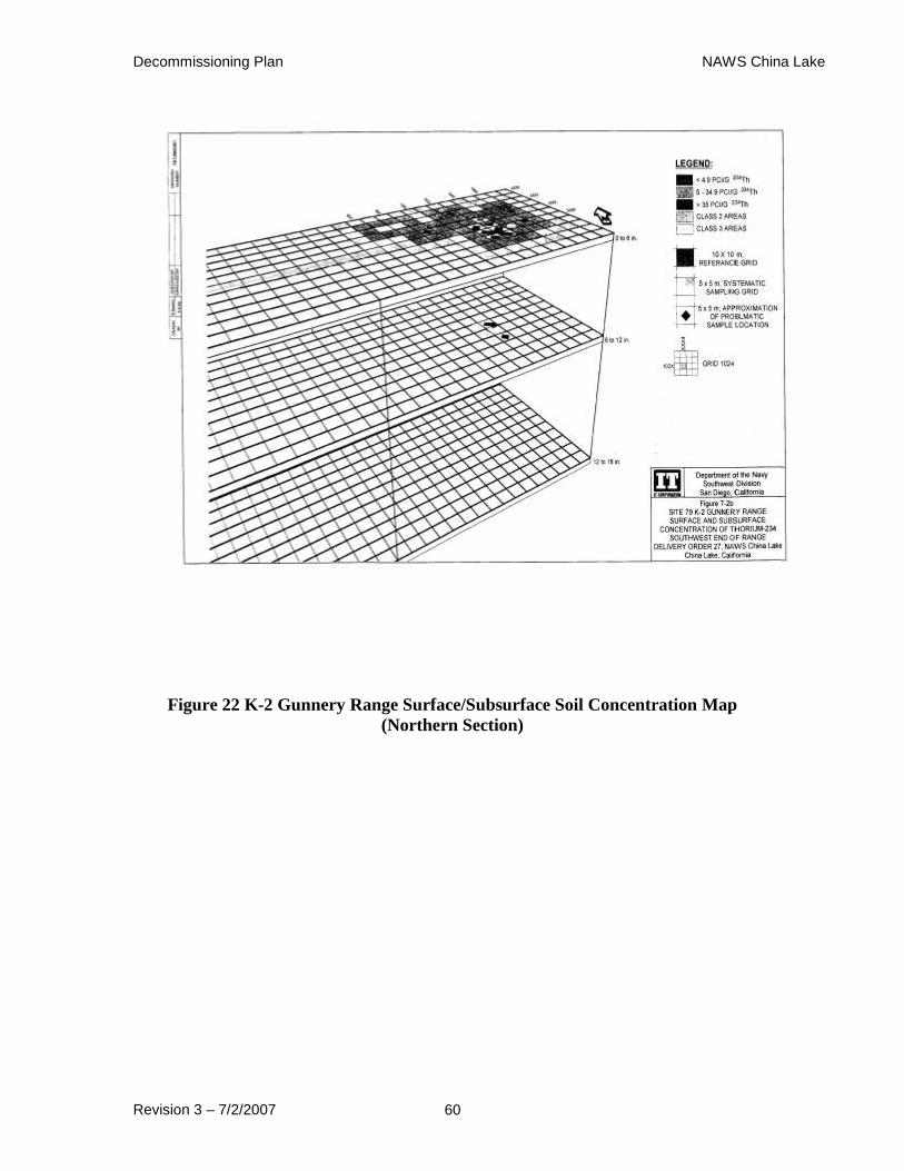
Decommissioning Plan NAWS China Lake
Revision 3 – 7/2/2007 60
Figure 22 K-2 Gunnery Range Surface/Subsurface Soil Concentration Map
(Northern Section)
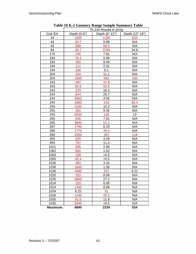
Decommissioning Plan NAWS China Lake
Revision 3 – 7/2/2007 61
Table 10 K-2 Gunnery Range Sample Summary Table
Grid ID# Depth (0-6") Depth (6"-12") Depth (12"-18")
44 1920 1180 534
44 43.7 5.98 N/A
45 589 69.6 N/A
84 40.7 2230 34.8
174 105 7.91 N/A
184 78.4 5.09 N/A
184 265 8.49 N/A
194 111 2.31 N/A
194 166 9.1 N/A
204 164 11.1 N/A
204 1060 662 160
193 497 47.8 N/A
203 95.9 53.5 N/A
243 370 16.3 N/A
244 644 25.7 N/A
244 3585 4.56 N/A
245 1683 210 82.4
254 2160 10.2 N/A
255 292 9.35 N/A
255 6530 126 13
265 638 7.81 N/A
265 3840 51.2 N/A
287 1780 6.29 N/A
285 1770 46.4 N/A
284 2450 187 118
305 530 4.29 N/A
993 787 11.3 N/A
1021 595 2.98 N/A
1062 600 1.52 N/A
1063 109 <0.5 N/A
1055 40.4 <0.5 N/A
1026 983 3.34 N/A
1036 1840 1.56 N/A
1036 4480 207 9.21
1025 203 8.06 N/A
1025 6890 27.2 N/A
1024 103 6.09 N/A
1024 1330 8.88 N/A
1034 6.25 91 N/A
1034 1430 45.3 N/A
1035 41.6 11.9 N/A
1035 5040 <0.5 N/A
Maximum: 6890 2230 534
Th-234 Results in pCi/g
Decommissioning Plan NAWS China Lake
Revision 3 – 7/2/2007 62
4.1.4 K-2 Gunnery Range (Berm and Area Behind Berm)
For each detector used during the characterization survey, thirty, one-minute gamma count rates were measured using a 2" by 2" sodium iodide (NaI) gamma scintillation detector system (Ludlum Instruments Model 2350-1 Data Logger coupled to a Ludlum Instruments Model 44-10 NaI or the equivalent). The area selected to obtain the readings was an area behind the gun line. This area was chosen due to its being located in a non-impacted area and its similar physical, chemical, geological, radiological, and biological characteristics as the area that was surveyed for the characterization survey effort.
The average background level was approximately 11,000 cpm gamma.
NWT performed a characterization survey of the berm and area behind the berm in April/May of 2004. Soil samples were taken in the loose sand areas of the berm. Data logging to obtain a three dimensional characterization of activity in the berm was done by randomly boring into the berm and dropping NaI detectors into the bore holes. A walkover scoping survey was also performed in the area behind the berm to identify any rounds that may have skipped or ricocheted over the berm. There were several areas in the grid behind the berm that indicated the presence of DU (greater than 2,000 net cpm). Figure 23 below provides a map that shows the results of the survey.
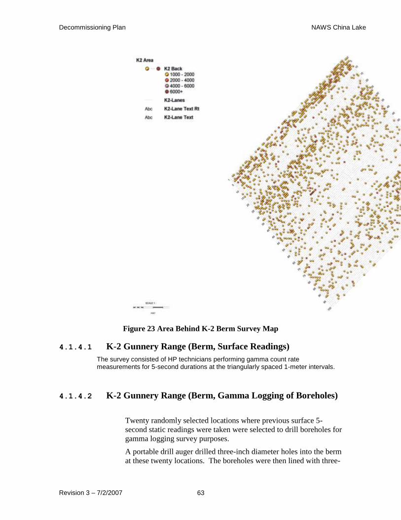
Decommissioning Plan NAWS China Lake
Revision 3 – 7/2/2007 63
Figure 23 Area Behind K-2 Berm Survey Map
4.1.4.1 K-2 Gunnery Range (Berm, Surface Readings)
The survey consisted of HP technicians performing gamma count rate measurements for 5-second durations at the triangularly spaced 1-meter intervals.
4.1.4.2 K-2 Gunnery Range (Berm, Gamma Logging of Boreholes)
Twenty randomly selected locations where previous surface 5-
second static readings were taken were selected to drill boreholes for
gamma logging survey purposes.
A portable drill auger drilled three-inch diameter holes into the berm
at these twenty locations. The boreholes were then lined with three-

Decommissioning Plan NAWS China Lake
Revision 3 – 7/2/2007 64
inch diameter PVC piping to prevent collapse of the surrounding
soils into the boreholes.
HP technicians then lowered 2” by 2” NaI detectors into the PVC
liners. Gamma count rate measurements were then taken for
duration of 10-seconds at one-foot increments along the entire
vertical length of the PVC liner at each of the twenty locations.
4.1.5 Waste Profile Samples of K-2 Berm
The soils created from the drilling operations in the berm were collected from each of the twenty locations.
The soils were then homogenously mixed and three sets of samples were obtained.
These samples were sent to an offsite laboratory for TCLP volatiles, TCLP semi-volatiles, isotopic uranium, isotopic thorium, gamma spectroscopy, and wet chemistry analyses.
A summary table presenting the results of the radiochemistry analyses is presented in Table 11 below:
Table 11 K-2 Berm Soil Sample Results Sample
ID#
Gamma Spectroscopy Results in pCi/g
Isotopic Uranium Results in pCi/g
Isotopic Thorium Results in pCi/g
Cs-137
K-40
Th-234
U-235
U-238
U-234
U-235
U-238
Th-228
Th-230
Th-232
K2B-1
-0.05
22.8
3310
44.7
2180
101
11
650
1.7
79
6.8
K2B-2
-0.35
21.2
6900
88
4340
790
113
6600
1.7
52
21
K2B-3
0.42
20
3800
50.2
2910
405
48
3120
4.1
63
0.9
4.1.6 G-6 Range
For each detector used during the characterization survey, thirty, one-minute gamma count rates were measured using a 2" by 2" sodium iodide
Decommissioning Plan NAWS China Lake
Revision 3 – 7/2/2007 65
(NaI) gamma scintillation detector. The area selected to obtain the readings was an area outside of the phalanx gun flight path. This area was chosen due to its being located in a non-impacted area and its similar physical, chemical, geological, radiological, and biological characteristics as the areas that were surveyed for the characterization survey effort.
The average background level was approximately 9,000 cpm gamma.
NWT performed scoping surveys of two areas, each measuring 48 by 100 meters in April/May of 2002. These areas were locations impacted by dispersion testing of the Phalanx gun system. The surveys were conducted with an array of NaI detectors arranged on a wheeled trailer hauled by a motorized “mule” (Ref. D-181). There were several areas in the two areas surveyed that indicated the presence of DU. Figure 24 and Figure 25 below provide maps that show the results of the surveys.
4.1.6.1 Investigation of DU Mobility in Soil (G-6 Range)
In 2003, the Navy and the University of Nevada, Las Vegas
(UNLV) conducted investigations into the extent of vertical and
lateral transport of uranium from DU penetrators at the Kennedy
Stands and G-6 ranges. These studies were reported and analyzed
by Argonne National Laboratory in 2003 (Ref. D-149, D-172).
The studies concluded that the mobility of DU from penetrators and
fragments was very limited. Most DU remained within four inches
vertically and 12 inches horizontally of individual penetrators.
At the G-6 Range, the DU penetrators exhibited little or no
corrosion, and relatively high uranium Kd values (> 500 mL/g) were
calculated. These findings suggest a limited potential for vertical
uranium migration via groundwater transport. Surface processes at
this location are dominated by water-driven (fluvial) processes,
while a combination of high winds and sparse vegetation may also
transport silt and some sand across the area. Infiltration potential
and soil permeability is high for this area, and the local topography
limits runoff. While large runoff events have the potential to move
uranium particles long distances, the low water availability together
with the very low degree of DU penetrator corrosion (due to low soil
pH) greatly limits the potential for fluvial transport of DU at this
site.
At the G-6 range (dispersion firing area), soil horizons from the
surface to 32 centimeters in depth had a lower soil pH (7.0 – 7.7)
and the highest uranium distribution coefficient (Kd) values (500-
800). Uranium sorption in the soil horizons from 33 to 86
centimeters in depth was considerably less. The Kd values of the
deeper horizons were 40±4 mL g-1, while the soil pH of those
horizons was 8.3. The increased soil pH and increased levels of
carbonate below 33 centimeters in depth likely results in a reduced
Kd value. Samples from the G6 Area soil horizons had uniformly

Decommissioning Plan NAWS China Lake
Revision 3 – 7/2/2007 66
low (less than measurable) clay content. Soil pH may be a
controlling factor for uranium sorption in the G6 Area.
The distribution coefficients (Kd) were determined under saturation
conditions, and therefore, are only valid under those conditions.
Because of soil conditions and topography, the likelihood of
saturation in the G6 Area is negligible, even after large storm events.
Argonne collected surface and subsurface soil samples during their
characterization effort (Ref.D-183) in the G-6 area. Surface soil
sample results ranged between a minimum of 1.27 pCi/g to 270
pCi/g with an average of 27.3 pCi/g. Subsurface (below 15 cm) soil
sample results ranged between 1.27 pCi/g to 1.72 pCi/g.
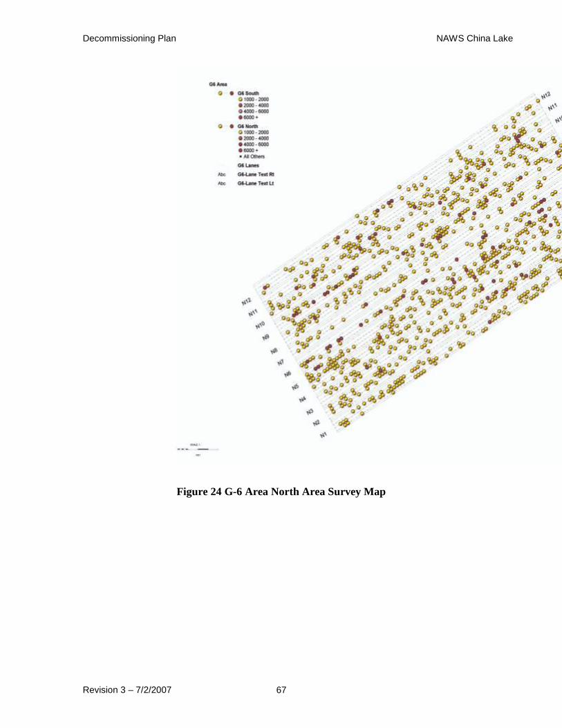
Decommissioning Plan NAWS China Lake
Revision 3 – 7/2/2007 67
Figure 24 G-6 Area North Area Survey Map
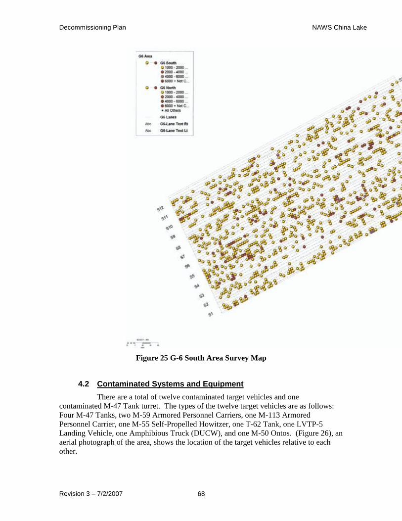
Decommissioning Plan NAWS China Lake
Revision 3 – 7/2/2007 68
Figure 25 G-6 South Area Survey Map
4.2 Contaminated Systems and Equipment
There are a total of twelve contaminated target vehicles and one
contaminated M-47 Tank turret. The types of the twelve target vehicles are as follows:
Four M-47 Tanks, two M-59 Armored Personnel Carriers, one M-113 Armored
Personnel Carrier, one M-55 Self-Propelled Howitzer, one T-62 Tank, one LVTP-5
Landing Vehicle, one Amphibious Truck (DUCW), and one M-50 Ontos. (Figure 26), an
aerial photograph of the area, shows the location of the target vehicles relative to each
other.

Decommissioning Plan NAWS China Lake
Revision 3 – 7/2/2007 69
Figure 26 Kennedy Stands Area Target Map
The targets have been surveyed for DU contamination, and all have been
found to be contaminated except for perhaps the amphibious truck which has no exterior
contamination. Although no external contamination has been found on the amphibious
truck, surface DU rounds have been found near the truck, and until proven otherwise the
truck must be considered contaminated. Depleted uranium 25mm rounds can also be
found on the surface in and around all the other targets. DU rounds have also been found
imbedded in the lone M-47 Tank turret and in the main targets themselves.
No other known radiation sources, besides natural radioactive material, are
present in the Kennedy Stands Target Area, however it is likely that some or all of the
targets had Radium dials during the DU tests, and those dials may have been damaged by
impacting rounds. Without a laboratory analysis of the radioactive material, it is not
possible to determine if the contamination in the vehicles is from DU or radium unless
there is some kind of indication that there are broken radium dials. Radium dials have
been removed from the targets according to historical documents and through on site
visual confirmation. It is, however, possible that some of the radium dials or toggle
switches were missed during the removal process. Most of the dials were probably
removed prior to the DU tests, but there is no way to be certain.
The figures and tables below present summaries of the targets and structures
in the Kennedy Stands Area.
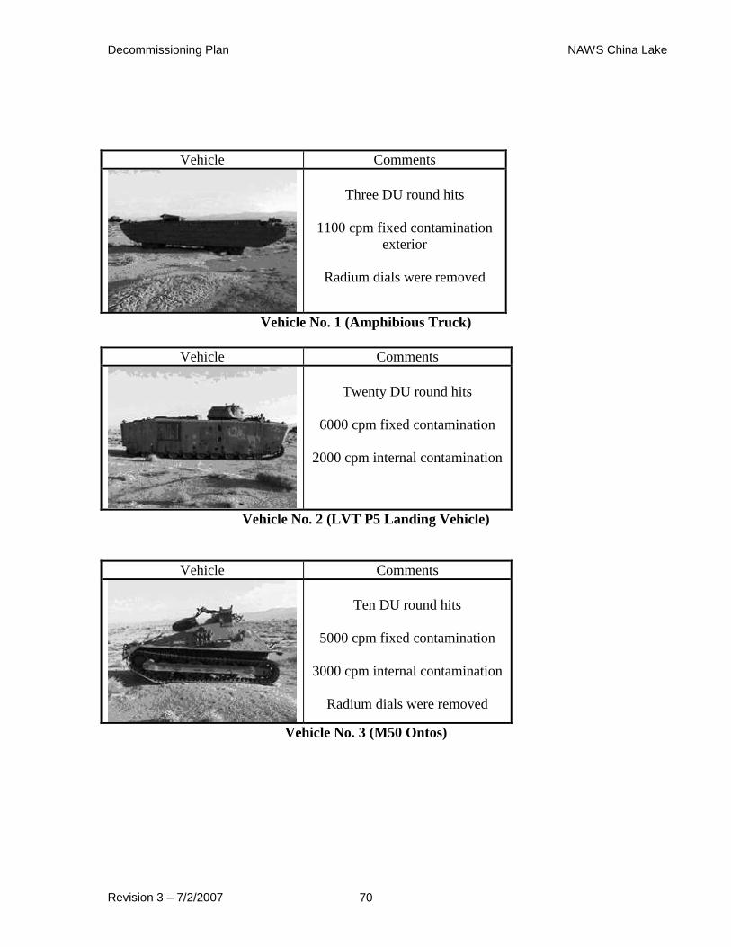
Decommissioning Plan NAWS China Lake
Revision 3 – 7/2/2007 70
Vehicle Comments
Three DU round hits
1100 cpm fixed contamination
exterior
Radium dials were removed
Vehicle No. 1 (Amphibious Truck)
Vehicle Comments
Twenty DU round hits
6000 cpm fixed contamination
2000 cpm internal contamination
Vehicle No. 2 (LVT P5 Landing Vehicle)
Vehicle Comments
Ten DU round hits
5000 cpm fixed contamination
3000 cpm internal contamination
Radium dials were removed
Vehicle No. 3 (M50 Ontos)
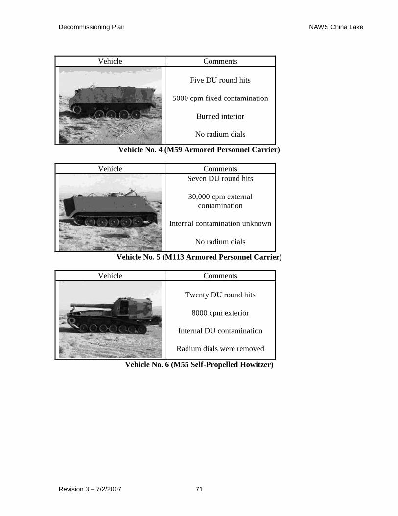
Decommissioning Plan NAWS China Lake
Revision 3 – 7/2/2007 71
Vehicle Comments
Five DU round hits
5000 cpm fixed contamination
Burned interior
No radium dials
Vehicle No. 4 (M59 Armored Personnel Carrier)
Vehicle Comments
Seven DU round hits
30,000 cpm external
contamination
Internal contamination unknown
No radium dials
Vehicle No. 5 (M113 Armored Personnel Carrier)
Vehicle Comments
Twenty DU round hits
8000 cpm exterior
Internal DU contamination
Radium dials were removed
Vehicle No. 6 (M55 Self-Propelled Howitzer)

Decommissioning Plan NAWS China Lake
Revision 3 – 7/2/2007 72
Vehicle Comments
Ten + DU round hits
30,000 cpm external
Internal contamination unknown
No radium dials
Vehicle No. 7 (M47 Tank)
Vehicle Comments
Twenty + DU round hits
40,000 cpm external
Internal contamination unknown
No radium/promethium dials
Vehicle No. 8 (T62 Tank)
Vehicle Comments
Ten + DU round hits
50,000+ cpm external
Internal contamination unknown
No radium dials
Vehicle No. 9 (M47 Tank)
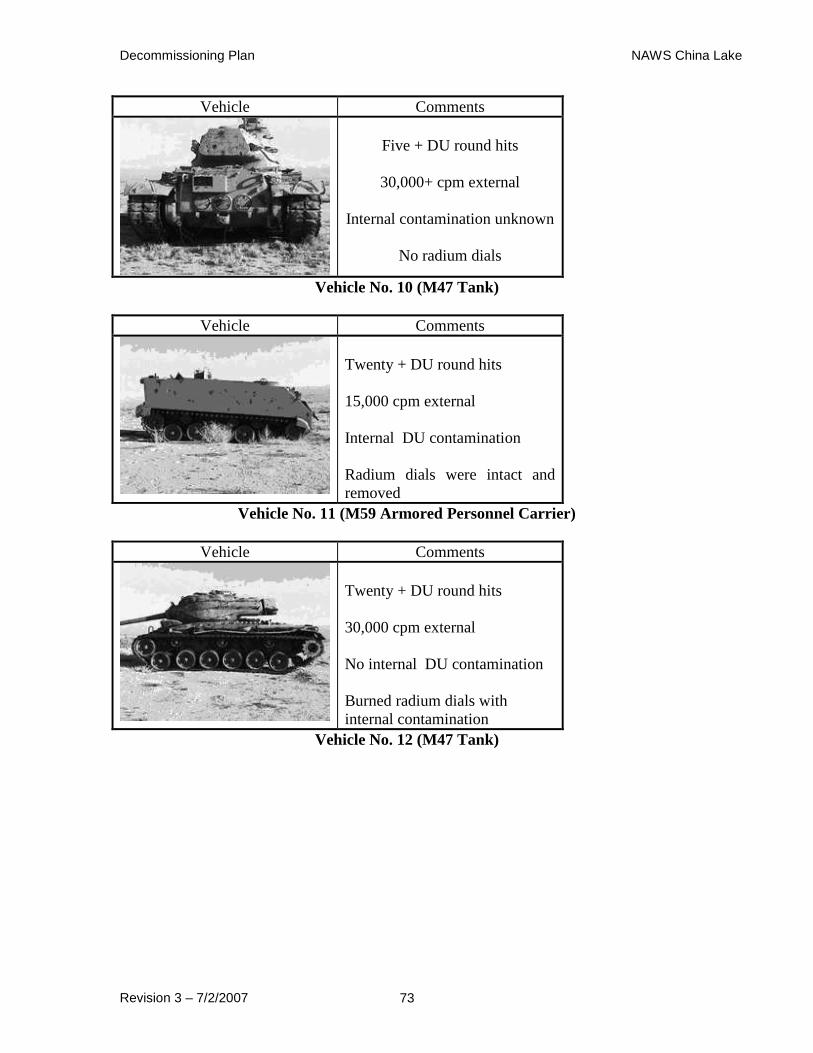
Decommissioning Plan NAWS China Lake
Revision 3 – 7/2/2007 73
Vehicle Comments
Five + DU round hits
30,000+ cpm external
Internal contamination unknown
No radium dials
Vehicle No. 10 (M47 Tank)
Vehicle Comments
Twenty + DU round hits
15,000 cpm external
Internal DU contamination
Radium dials were intact and
removed
Vehicle No. 11 (M59 Armored Personnel Carrier)
Vehicle Comments
Twenty + DU round hits
30,000 cpm external
No internal DU contamination
Burned radium dials with
internal contamination
Vehicle No. 12 (M47 Tank)
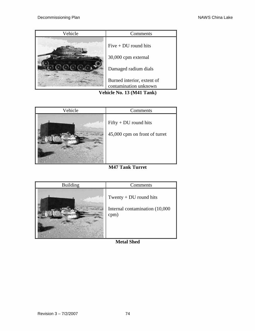
Decommissioning Plan NAWS China Lake
Revision 3 – 7/2/2007 74
Vehicle Comments
Five + DU round hits
30,000 cpm external
Damaged radium dials
Burned interior, extent of
contamination unknown
Vehicle No. 13 (M41 Tank)
Vehicle Comments
Fifty + DU round hits
45,000 cpm on front of turret
M47 Tank Turret
Building Comments
Twenty + DU round hits
Internal contamination (10,000
cpm)
Metal Shed
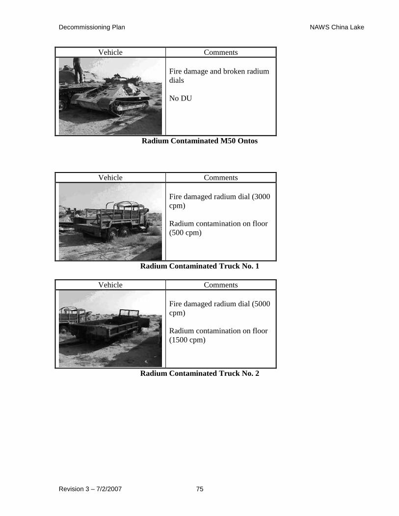
Decommissioning Plan NAWS China Lake
Revision 3 – 7/2/2007 75
Vehicle Comments
Fire damage and broken radium
dials
No DU
Radium Contaminated M50 Ontos
Vehicle Comments
Fire damaged radium dial (3000
cpm)
Radium contamination on floor
(500 cpm)
Radium Contaminated Truck No. 1
Vehicle Comments
Fire damaged radium dial (5000
cpm)
Radium contamination on floor
(1500 cpm)
Radium Contaminated Truck No. 2
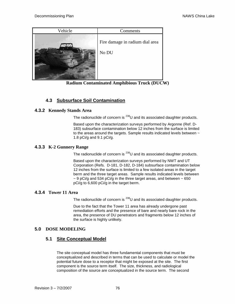
Decommissioning Plan NAWS China Lake
Revision 3 – 7/2/2007 76
Vehicle Comments
Fire damage in radium dial area
No DU
Radium Contaminated Amphibious Truck (DUCW)
4.3 Subsurface Soil Contamination
4.3.2 Kennedy Stands Area
The radionuclide of concern is 238
U and its associated daughter products.
Based upon the characterization surveys performed by Argonne (Ref. D-183) subsurface contamination below 12 inches from the surface is limited to the areas around the targets. Sample results indicated levels between ~ 1.8 pCi/g and 9.1 pCi/g.
4.3.3 K-2 Gunnery Range
The radionuclide of concern is 238
U and its associated daughter products.
Based upon the characterization surveys performed by NWT and UT Corporation (Refs. D-181, D-182, D-184) subsurface contamination below 12 inches from the surface is limited to a few isolated areas in the target berm and the three target areas. Sample results indicated levels between ~ 9 pCi/g and 534 pCi/g in the three target areas, and between ~ 650 pCi/g to 6,600 pCi/g in the target berm.
4.3.4 Tower 11 Area
The radionuclide of concern is 238
U and its associated daughter products.
Due to the fact that the Tower 11 area has already undergone past remediation efforts and the presence of bare and nearly bare rock in the area, the presence of DU penetrators and fragments below 12 inches of the surface is highly unlikely.
5.0 DOSE MODELING
5.1 Site Conceptual Model
The site conceptual model has three fundamental components that must be conceptualized and described in terms that can be used to calculate or model the potential future dose to a receptor that might be exposed at the site. The first component is the source term itself. The size, thickness, and radiological composition of the source are conceptualized in the source term. The second

Decommissioning Plan NAWS China Lake
Revision 3 – 7/2/2007 77
component of the site conceptual model is the physical characteristics of the site itself. The site is described in the physical abstraction that includes physical and hydraulic characteristics of the site and its potentially impacted environs. The third component that must be conceptualized is the range of plausible human exposure scenarios, which are described primarily by factors that are associated with human behavior and metabolic physics.
5.1.2 Source Term
The source term used to project potential future dose is derived from knowledge about the source material itself and previously completed radiological assessments of the residual radioactivity at the site. The source term is defined by its radionuclide composition, in this case DU and its daughter products, as well as its lateral and vertical deposition (spatial configuration) on and in the surface soil of the ranges where it was deposited.
Conceptually, there are three discrete source terms for the NAWS China Lake site. The primary source term involves the depleted uranium projectiles, fragments and oxidation products that litter the ranges and targets where the munitions were test fired: the surface soil source term. A secondary source term, the subsurface soil source term, acknowledges that radioactivity exists under the surface of the sand/soil from projectiles, fragments and oxidation products that penetrated the surface to varying depths from the high energy of the explosives that propelled the projectiles to their targets. Subsurface DU (depths below 15 cm) will not be addressed as part of the source term in this DP. There is no reliable, economical methodology to determine the presence (or absence) nor the extent of any subsurface contamination. Additionally, the presence of subsurface UXO on the ranges presents a substantial hazard to identification and recovery of any DU at depth.
5.1.2.1 Primary Source Term (Kennedy Stands Area)
The primary source term is comprised of DU projectiles, fragments
and oxidation products visible and accessible on the surface and
within 15 cm of the surface of the ground on the ranges where the
DU was fired. At the Kennedy Stands test site, the vehicles used as
targets are also visibly contaminated with DU projectiles which
partially and completely penetrated the armor and/or metal skins of
the targets. There is some variability in the observable DU
depositions owing to the random nature of the fall of the DU shot
around and in the targets and surface and subsurface sand/soil.
Given the fall of shot and fragmentation of many of the brittle DU
projectiles, the distribution of DU in this layer of sand/soil is not
uniform. As has been shown in the Argonne Laboratory study (Ref.
D-149), DU and its oxides have not migrated far from where they
were deposited on or in the sand/soil more than fifteen years prior to
the surveys. Based upon the results of the characterization surveys
performed by NWT and Argonne (Refs. D-181, D-182, D-149) and
a large majority of the DU penetrators and fragments exist in an
approximate 250 meter by 800 meter area containing and
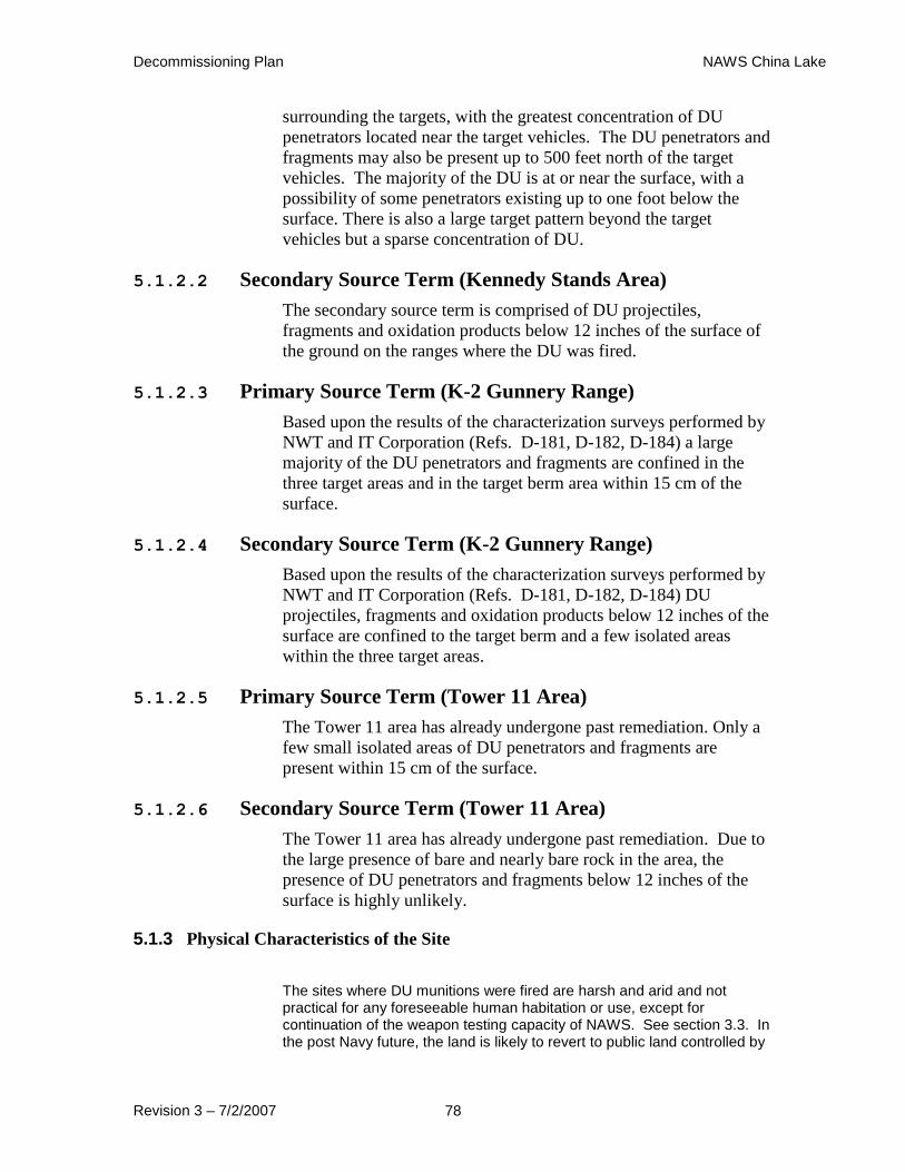
Decommissioning Plan NAWS China Lake
Revision 3 – 7/2/2007 78
surrounding the targets, with the greatest concentration of DU
penetrators located near the target vehicles. The DU penetrators and
fragments may also be present up to 500 feet north of the target
vehicles. The majority of the DU is at or near the surface, with a
possibility of some penetrators existing up to one foot below the
surface. There is also a large target pattern beyond the target
vehicles but a sparse concentration of DU.
5.1.2.2 Secondary Source Term (Kennedy Stands Area)
The secondary source term is comprised of DU projectiles,
fragments and oxidation products below 12 inches of the surface of
the ground on the ranges where the DU was fired.
5.1.2.3 Primary Source Term (K-2 Gunnery Range)
Based upon the results of the characterization surveys performed by
NWT and IT Corporation (Refs. D-181, D-182, D-184) a large
majority of the DU penetrators and fragments are confined in the
three target areas and in the target berm area within 15 cm of the
surface.
5.1.2.4 Secondary Source Term (K-2 Gunnery Range)
Based upon the results of the characterization surveys performed by
NWT and IT Corporation (Refs. D-181, D-182, D-184) DU
projectiles, fragments and oxidation products below 12 inches of the
surface are confined to the target berm and a few isolated areas
within the three target areas.
5.1.2.5 Primary Source Term (Tower 11 Area)
The Tower 11 area has already undergone past remediation. Only a
few small isolated areas of DU penetrators and fragments are
present within 15 cm of the surface.
5.1.2.6 Secondary Source Term (Tower 11 Area)
The Tower 11 area has already undergone past remediation. Due to
the large presence of bare and nearly bare rock in the area, the
presence of DU penetrators and fragments below 12 inches of the
surface is highly unlikely.
5.1.3 Physical Characteristics of the Site
The sites where DU munitions were fired are harsh and arid and not practical for any foreseeable human habitation or use, except for continuation of the weapon testing capacity of NAWS. See section 3.3. In the post Navy future, the land is likely to revert to public land controlled by
Decommissioning Plan NAWS China Lake
Revision 3 – 7/2/2007 79
the Bureau of Land Management as other public lands in the Indian Wells Valley.
The use of water from shallow wells has limited uses due to extremely poor quality. It is identified as non potable as it now exists and any future use would lead to decreasing quality. The water levels in some areas of the zone have been noted to be decreasing in recent years likely due to limited agricultural pumping. It is not considered reasonable that drinking water will ever be drawn from shallow sources. (Ref. D-183 2003-08)
Removal of all DU and residual DU contamination is not practical, reasonable or cost-effective. Also, the presence of subsurface UXO makes the operation of remediation of depleted uranium projectiles and fragments below the surface an extremely hazardous operation.
Decommissioning of the DU impacted ranges and other outdoor facilities at NAWS will be limited in scope: no attempt will be made to find and remove all DU from these sites and some contaminated sand and soil will be allowed to remain in place.
5.1.4 Plausible Human Exposure Scenarios and Pathways
The primary potential human receptors based on the forecasted land use and discussions with Navy range personnel include:
Range workers
Trespassers
Archaeologists
Residential Farmer
Factors which have also been considered when determining potential exposures are the foreseeable future, where the Navy remains in control of the areas, and the more distant future when the areas may not be under Navy control. The critical groups will change under those differing scenarios. Under the first scenario, the range workers are considered the critical group. Whole penetrators would not be an exposure issue. As Navy SOP’s for UXO prohibit casual retrieval of range debris. If the Navy eventually surrenders control of the areas, the archeologist will become the critical group with trespassers comprising a possible sub group.
Currently, civilian range workers are present on site, and their time and exposure is greater than that of military personnel. This difference in exposure time is because military personnel are on site generally for training purposes, a shorter timeframe than for range workers. In addition, trespassers have been observed at the eastern edge of the site (North Range) (not near any of the DU impacted areas). Trespassers may be future potential receptors and may come into the areas of the site containing DU for short periods of time after the Navy is no longer present at NAWS. Archaeologists may also be potential future receptors since artifacts have occasionally been observed in the soil at the Kennedy Stands area only.
Range workers of ages >18 years were identified as having the potential for the longest timeframe exposure to the impacted arrange areas. Exposure of these range workers subsumes exposure of military personnel who are likely to be training at the site for shorter periods of time. Therefore, if risk to the range workers is acceptable, military personnel will also be protected. Based on a survey at the site in the summer of 2002, range workers are likely to be present infrequently at any of the three impacted areas with an estimate of 19.19 days/year. This surveyed value was doubled to 38.44 days/year which equates to 3.1
Decommissioning Plan NAWS China Lake
Revision 3 – 7/2/2007 80
years over a period of 30 years (RESRAD default exposure duration). Soil ingestion rates were based on 100 mg/day (36.5 g/year). Inhalation was
also calculated and inhalation rates were 20 m3/ day (7,300 m
3/year). (Ref
D-170)
Archaeologists have been investigated and have been determined to be a critical group after the Navy is not present at NAWS. (Ref. D-170). A university- based archaeologist might conduct field studies at the site for a number of years, even up to 10 years.
Each year, the professor and 10–15 students and 2-3 graduate students might dig for 6-8 weeks, 5-6 days per week, 8 hours per day. This equates to 10 years over a period of 30 years (RESRAD default exposure duration). All of the time onsite would be spent outdoors. (Ref. D-170)
At the time of exposure, due to corrosion and weathering, whole penetrators would have been reduced to localized contaminated spots of soil. Because such persons may have close contact with soil, the central tendency of 50 mg soil ingestion/day was assumed but for the reasonable maximum four times higher, 200 mg soil ingestion/day (73 g/year) was assumed. Inhalation rates are the same as for range workers.
As in the case of the archaeologists, trespassers should be investigated after the Navy is not present at NAWS. Trespassers are defined as individuals who are 12 to 18 years old from the surrounding areas who may like to intrude on an area of military significance. This group is considered to be a more sensitive receptor than an older adult trespasser. Children less than 12 years of age were not considered frequent trespassers on the site because they remain closer to home under adult supervision. The trespasser soil ingestion rates were 200 mg/ day (73 g/year); their breathing rates were 12 m
3/ day, (4,380 m
3/year). Both of
these rates are based on EPA guidance (upper bound). They would assume to be on-site for up to 12 days/year based on observations from workers on site. This equates to 1 year over a period of 30 years (RESRAD default exposure duration). All of the time onsite would be spent outdoors. (Ref. D-170)
Although there is a lack of plentiful water, and an increasing demand on water resources, a residential farmer scenario was also chosen as potential human receptor in order to provide a comparison to the range worker, archaeologist, and trespasser scenarios. The residential farmer soil ingestion rates were 100 mg/ day (36.5 g/year); their breathing rates were 23 m
3/ day, (8,400 m
3/year). Both of these rates are RESRAD
default values. They would assume to be on-site 365 days/year for a period of 30 years which is the RESRAD default exposure duration for estimating exposure to residential farmers. Drinking water would not come from on-site sources. Fifty percent of the time on-site would be spent indoors and 25 percent of the time on-site would be spent outdoors which are both RESRAD default parameters.
Currently, there is no exposure to area residents as isotopes have not been shown to migrate downgradient from the areas of concern. Measurements of depleted uranium at other sites where depleted uranium munitions were used have indicated only localized contamination at the ground surface. This finding was also supported at this site where soils in the areas of concern (identified because they were utilized in the shelling process) were found to contain concentrations of depleted uranium
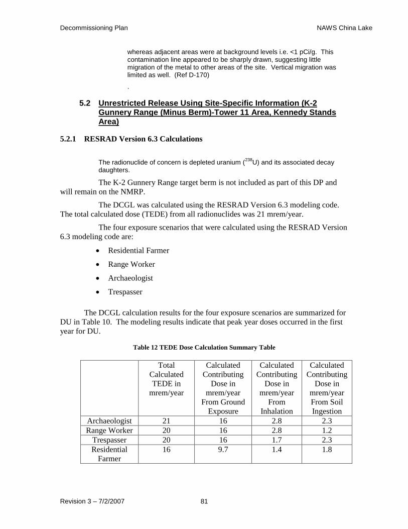
Decommissioning Plan NAWS China Lake
Revision 3 – 7/2/2007 81
whereas adjacent areas were at background levels i.e. <1 pCi/g. This contamination line appeared to be sharply drawn, suggesting little migration of the metal to other areas of the site. Vertical migration was limited as well. (Ref D-170)
.
5.2 Unrestricted Release Using Site-Specific Information (K-2 Gunnery Range (Minus Berm)-Tower 11 Area, Kennedy Stands Area)
5.2.1 RESRAD Version 6.3 Calculations
The radionuclide of concern is depleted uranium (238
U) and its associated decay daughters.
The K-2 Gunnery Range target berm is not included as part of this DP and
will remain on the NMRP.
The DCGL was calculated using the RESRAD Version 6.3 modeling code.
The total calculated dose (TEDE) from all radionuclides was 21 mrem/year.
The four exposure scenarios that were calculated using the RESRAD Version
6.3 modeling code are:
Residential Farmer
Range Worker
Archaeologist
Trespasser
The DCGL calculation results for the four exposure scenarios are summarized for
DU in Table 10. The modeling results indicate that peak year doses occurred in the first
year for DU.
Table 12 TEDE Dose Calculation Summary Table
Total
Calculated
TEDE in
mrem/year
Calculated
Contributing
Dose in
mrem/year
From Ground
Exposure
Calculated
Contributing
Dose in
mrem/year
From
Inhalation
Calculated
Contributing
Dose in
mrem/year
From Soil
Ingestion
Archaeologist 21 16 2.8 2.3
Range Worker 20 16 2.8 1.2
Trespasser 20 16 1.7 2.3
Residential
Farmer
16 9.7 1.4 1.8
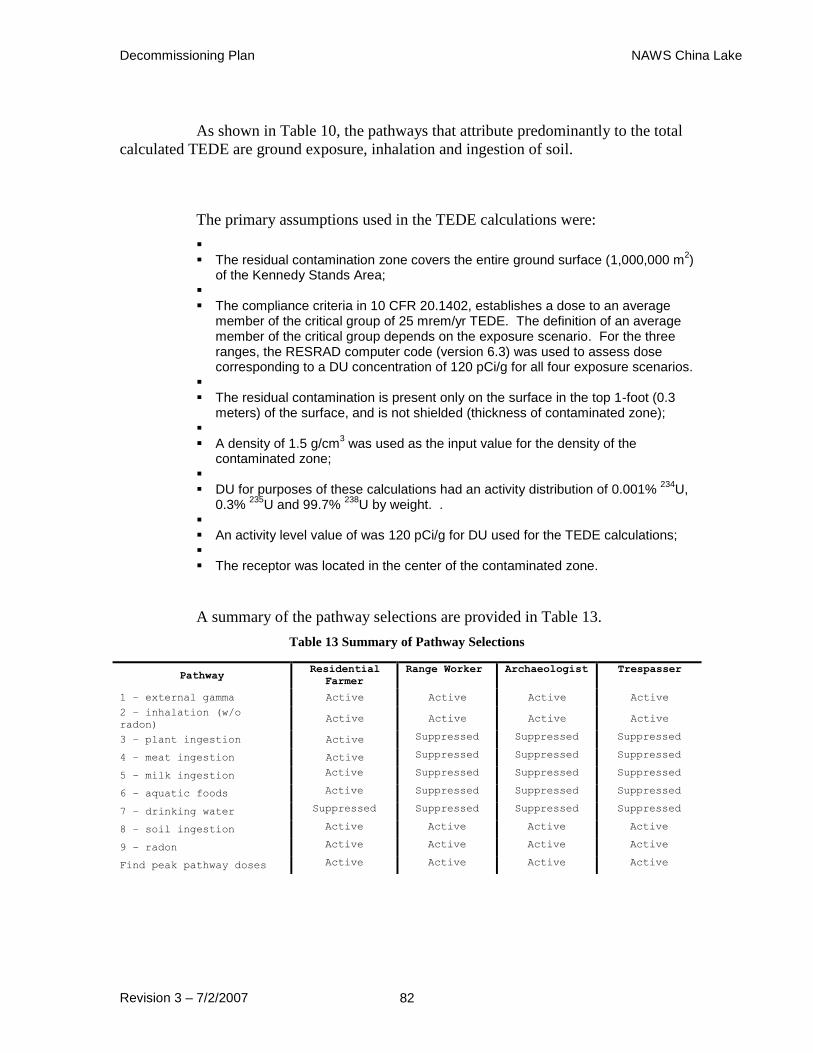
Decommissioning Plan NAWS China Lake
Revision 3 – 7/2/2007 82
As shown in Table 10, the pathways that attribute predominantly to the total
calculated TEDE are ground exposure, inhalation and ingestion of soil.
The primary assumptions used in the TEDE calculations were:
The residual contamination zone covers the entire ground surface (1,000,000 m
2)
of the Kennedy Stands Area; The compliance criteria in 10 CFR 20.1402, establishes a dose to an average
member of the critical group of 25 mrem/yr TEDE. The definition of an average member of the critical group depends on the exposure scenario. For the three ranges, the RESRAD computer code (version 6.3) was used to assess dose corresponding to a DU concentration of 120 pCi/g for all four exposure scenarios.
The residual contamination is present only on the surface in the top 1-foot (0.3
meters) of the surface, and is not shielded (thickness of contaminated zone); A density of 1.5 g/cm
3 was used as the input value for the density of the
contaminated zone; DU for purposes of these calculations had an activity distribution of 0.001%
234U,
0.3% 235
U and 99.7% 238
U by weight. . An activity level value of was 120 pCi/g for DU used for the TEDE calculations; The receptor was located in the center of the contaminated zone.
A summary of the pathway selections are provided in Table 13.
Table 13 Summary of Pathway Selections
Pathway Residential
Farmer
Range Worker Archaeologist Trespasser
1 – external gamma Active Active Active Active
2 – inhalation (w/o
radon) Active Active Active Active
3 – plant ingestion Active Suppressed Suppressed Suppressed
4 – meat ingestion Active Suppressed Suppressed Suppressed
5 – milk ingestion Active Suppressed Suppressed Suppressed
6 – aquatic foods Active Suppressed Suppressed Suppressed
7 – drinking water Suppressed Suppressed Suppressed Suppressed
8 – soil ingestion Active Active Active Active
9 – radon Active Active Active Active
Find peak pathway doses Active Active Active Active
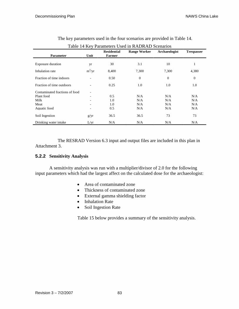
Decommissioning Plan NAWS China Lake
Revision 3 – 7/2/2007 83
The key parameters used in the four scenarios are provided in Table 14.
Table 14 Key Parameters Used in RADRAD Scenarios
Parameter Unit
Residential
Farmer
Range Worker Archaeologist Trespasser
Exposure duration yr 30 3.1 10 1
Inhalation rate m3/yr 8,400 7,300 7,300 4,380
Fraction of time indoors - 0.50 0 0 0
Fraction of time outdoors - 0.25 1.0 1.0 1.0
Contaminated fractions of food -
Plant food - 0.5 N/A N/A N/A
Milk - 1.0 N/A N/A N/A
Meat - 1.0 N/A N/A N/A
Aquatic food - 0.5 N/A N/A N/A
Soil Ingestion g/yr 36.5 36.5 73 73
Drinking water intake L/yr N/A N/A N/A N/A
The RESRAD Version 6.3 input and output files are included in this plan in
Attachment 3.
5.2.2 Sensitivity Analysis
A sensitivity analysis was run with a multiplier/divisor of 2.0 for the following
input parameters which had the largest affect on the calculated dose for the archaeologist:
Area of contaminated zone
Thickness of contaminated zone
External gamma shielding factor
Inhalation Rate
Soil Ingestion Rate
Table 15 below provides a summary of the sensitivity analysis.
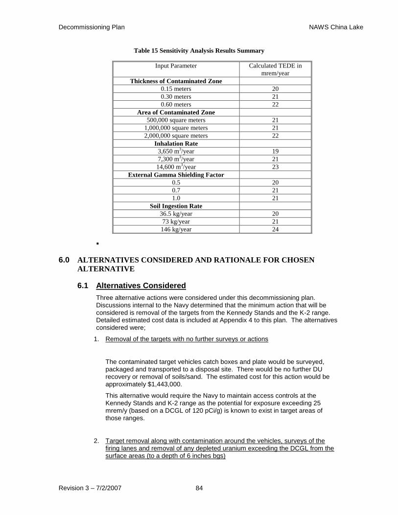
Decommissioning Plan NAWS China Lake
Revision 3 – 7/2/2007 84
Table 15 Sensitivity Analysis Results Summary
6.0 ALTERNATIVES CONSIDERED AND RATIONALE FOR CHOSEN
ALTERNATIVE
6.1 Alternatives Considered
Three alternative actions were considered under this decommissioning plan. Discussions internal to the Navy determined that the minimum action that will be considered is removal of the targets from the Kennedy Stands and the K-2 range. Detailed estimated cost data is included at Appendix 4 to this plan. The alternatives considered were;
1. Removal of the targets with no further surveys or actions
The contaminated target vehicles catch boxes and plate would be surveyed, packaged and transported to a disposal site. There would be no further DU recovery or removal of soils/sand. The estimated cost for this action would be approximately $1,443,000.
This alternative would require the Navy to maintain access controls at the Kennedy Stands and K-2 range as the potential for exposure exceeding 25 mrem/y (based on a DCGL of 120 pCi/g) is known to exist in target areas of those ranges.
2. Target removal along with contamination around the vehicles, surveys of the firing lanes and removal of any depleted uranium exceeding the DCGL from the surface areas (to a depth of 6 inches bgs)
Input Parameter Calculated TEDE in
mrem/year
Thickness of Contaminated Zone
0.15 meters 20
0.30 meters 21
0.60 meters 22
Area of Contaminated Zone
500,000 square meters 21
1,000,000 square meters 21
2,000,000 square meters 22
Inhalation Rate
3,650 m3/year 19
7,300 m3/year 21
14,600 m3/year 23
External Gamma Shielding Factor
0.5 20
0.7 21
1.0 21
Soil Ingestion Rate
36.5 kg/year 20
73 kg/year 21
146 kg/year 24

Decommissioning Plan NAWS China Lake
Revision 3 – 7/2/2007 85
This alternative would perform the actions described above in Alternative 1 but would additionally remove DU penetrators, fragments and soils and sands from the Kennedy Stands and K-2 range that exceed the DCGL to a depth of 15 centimeters (6 inches) bgs. Confirmatory surveys would be performed at Tower 11 to verify results of the prior decommissioning activities at that site. Any resultant waste materials would be packaged, transported and disposed of at an appropriate disposal site.
Estimated costs for this alternative are approximately $ 9,921,400.00. The resultant calculated exposure to the critical group, again range workers, is estimated to be 20 mrem/y.
Access controls related to control of radioactive materials would not be required as the calculated exposure under this alternative would be less than 25 mrem/y
3. Remove the targets and removal 1 foot of soil from the surface of the firing lanes, mechanically screen the soil and remove any DU penetrators, fragments or soils which exceed the DCGL.
Alternative 3 would remove the top 1 foot of soil/sand from the target areas of the Kennedy Stands and the K-2 range and run the materials through a conveyor system equipped with a monitoring system comprised of 2X2 NaI detectors. All materials exceeding the DCGL would be removed from the system for packaging and disposal. The resultant sand/soils from the conveyor system would be placed in discreet piles (nominally 100 cubic yards) and sampled to determine the DU concentrations.
This option still requires the initial UXO and radiation screening prior to excavation. UXO personnel would also be required to be present while the material is processed through the conveyor system.
The estimated costs for this alternative are approximately $20,800,000. The dose saved would be negligible as the sole benefit would be the assurance that all soils in the top 1 foot of soils met the DCGL.
6.2 Rationale for Chosen Alternative
.
Based on the balance between cost, potential exposures and license
requirements, Alternative 2 is proposed as the remedial action. There will be no major
impacts on the geology, hydrology, air quality or ecology in and around the site utilizing
this alternative. The TEDE to either range workers (current critical group) or the
archeologist (distant future critical group) is well below the 25 mrem/y limit as required.
The use of this alternative would allow the Navy to cease the monitoring and access
control requirements for the three areas discussed.
There will be no adverse consequence to the surrounding community under
this alternative either in terms of health effect or property valuations based on the
scenarios discussed in other portions of this plan.

Decommissioning Plan NAWS China Lake
Revision 3 – 7/2/2007 86
7.0 ALARA ANALYSIS
Areas will be remediated to below the DCGL value of 120 pCi/g. This will
result in TEDE of 21 mrem/yr which is below the NRC’s standard of 25 mrem/yr
TEDE.
In order to comply with NRC’s standards for protection against radiation
(10 CFR 20.1402 and 20.1403 [a]), the DON performed an analysis to demonstrate
that residual DU concentration of 120 pCi/g is ALARA. This analysis was
performed in accordance with the method described in Appendix N of Volume 2 of
NUREG-1757 (NRC 2003). Per NUREG 1757, the residual radioactivity level that
is ALARA is the concentration at which the benefit from removal equals the cost of
removal. Benefit estimated from a reduction in the level of residual radioactivity is
the monetary value of the collective averted dose to future occupants of the site.
Appendix N of the NUREG 1757 presents the following equation to calculate
present worth of the future collective averted dose:
r
e
DCGL
ConcFAPADPW
Nr
W
Dcollective
)(1.025.0)(
where
PW (Adcollective) Present worth of the future averted dose
PD population density for the critical group scenario in people per square meter
A area being evaluated in square meters
0.025 annual dose to an average member of the critical group from residual radioactivity at the DCGLW concentration in rem/y
F effectiveness, or fraction of residual radioactivity removed by the remedial action
Conc. average concentration of residual radioactivity in the area being evaluated in units of activity per unit area for buildings or activity per
unit area volume for soils
DCGLW derived concentration guideline equivalent to the average concentration of residual radioactivity that would give a dose of 25 mrem/y to the average member of the critical group, in the same units as “Conc.”
r monetary discount rate in units per year
λ radiological decay constant for the radionuclide in units per year
N number of years over which the collective dose will be calculated.
The total cost for remedial action is calculated using the following equation:
CostT = CostR + CostWD + CostACC + CostTF + CostWDose + CostPDose + Costother
Where
CostR monetary cost of the remedial action
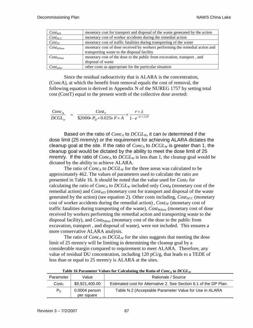
Decommissioning Plan NAWS China Lake
Revision 3 – 7/2/2007 87
CostWD monetary cost for transport and disposal of the waste generated by the action
CostACC monetary cost of worker accidents during the remedial action
CostTF monetary cost of traffic fatalities during transporting of the waste
CostWDose monetary cost of dose received by workers performing the remedial action and
transporting waste to the disposal facility
CostPDose monetary cost of the dose to the public from excavation, transport , and
disposal of waste
Costother other costs as appropriate for the particular situation
Since the residual radioactivity that is ALARA is the concentration,
(ConcA), at which the benefit from removal equals the cost of removal, the
following equation is derived in Appendix N of the NUREG 1757 by setting total
cost (CostT) equal to the present worth of the collective dose averted:
NrD
T
w
A
e
r
AFP
Cost
DCGL
Conc)(1025.02000$
Based on the ratio of ConcA to DCGLW, it can be determined if the dose limit (25 mrem/y) or the requirement for achieving ALARA dictates the cleanup goal at the site. If the ratio of ConcA to DCGLW is greater than 1, the cleanup goal would be dictated by the ability to meet the dose limit of 25 mrem/y. If the ratio of ConcA to DCGLW is less than 1, the cleanup goal would be
dictated by the ability to achieve ALARA.
The ratio of ConcA to DCGLW for the three areas was calculated to be
approximately 462. The values of parameters used to calculate the ratio are
presented in Table 16. It should be noted that the value used for CostT for
calculating the ratio of ConcA to DCGLW included only CostR (monetary cost of the
remedial action) and CostWD (monetary cost for transport and disposal of the waste
generated by the action) (see equation 2). Other costs including, CostACC (monetary
cost of worker accidents during the remedial action) , CostTF (monetary cost of
traffic fatalities during transporting of the waste), CostWdose (monetary cost of dose
received by workers performing the remedial action and transporting waste to the
disposal facility), and CostPdose (monetary cost of the dose to the public from
excavation, transport , and disposal of waste), were not included. This ensures a
more conservative ALARA analysis.
The ratio of ConcA to DCGLW for the sites suggests that meeting the dose
limit of 25 mrem/y will be limiting in determining the cleanup goal by a
considerable margin compared to requirement to meet ALARA. Therefore, any
value of residual DU concentration, including 120 pCi/g, that leads to a TEDE of
less than or equal to 25 mrem/y is ALARA at the sites.
Table 16 Parameter Values for Calculating the Ratio of ConcA to DCGLW
Parameter Value Rationale / Source
CostT $9,921,400.00 Estimated cost for Alternative 2. See Section 6.1 of the DP Plan.
PD 0.0004 person per square
Table N.2 (Acceptable Parameter Value for Use in ALARA

Decommissioning Plan NAWS China Lake
Revision 3 – 7/2/2007 88
meter Analyses) in Appendix N of NUREG 1757.
F 0.99 (Site-specific Average U-238 concentration [95.98 pCi/g] – 120 pCi/g) / (Site-specific Average U-238 concentration [95.98 pCi/g)
A 1,157,566 square meters
Area encompassing the three areas.
r 0.03 per year Table N.2 (Acceptable Parameter Value for Use in ALARA Analyses) in Appendix N of NUREG 1757.
λ 1.55 E-10 per year
Radiological decay constant for U-238.
N 1000 years Table N.2 (Acceptable Parameter Value for Use in ALARA Analyses) in Appendix N of NUREG 1757.
8.0 PLANNED DECOMMISSIONING ACTIVITIES
8.1 General considerations for the Planning of Decommissioning Activities
The following is a list of general consideration for the planning of decommissioning activities for the DU ranges:
the site is contaminated with depleted uranium which is distributed over large land areas
the site is an active weapons range contaminated with unexploded ordnance, making collection of depleted uranium projectiles and fragments below the surface an extremely hazardous and expensive operation
the presence of natural uranium in the rocks and soils at the site make field detection of low levels of depleted uranium difficult, except by expensive surveying and sampling methods when considering the large land areas involved
the site has no practical alternative uses far into the foreseeable future
migration of depleted uranium from penetrators and fragments in the sand/soil has been shown to be extremely slow, and the depleted uranium that does migrate from the penetrators and fragments does not travel far in the arid conditions present at NAWS China Lake
there is a clay barrier beneath the sand/soil (at G-6 Test Range and Kennedy Stands Target Area) that effectively prevents the depleted uranium from migrating to the groundwater aquifer
doses in excess of 25 mrem/y from the depleted uranium, as it currently exists on the ranges, are highly unlikely based on the referenced, detailed, dose assessment and RESRAD model run
as a U. S. Navy facility, sufficient institutional controls are in place, and will remain in place far into the foreseeable future, to prevent inadvertent exposures
the ranges that were impacted by the use of DU are off-limits to casual visitors and not accessed routinely by base personnel. The ranges are also peppered with other hazards, such as unexploded ordnance, that require access to be strictly controlled.
Decommissioning Plan NAWS China Lake
Revision 3 – 7/2/2007 89
8.2 Scope of Planned Decommissioning Activities
The scope of decommissioning activities at NAWS will include:
the removal and disposal of contaminated target vehicles, steel/armor plate targets and other target scrap
wrapping/containing the contaminated target vehicles and structural steel for shipment
retrieving depleted uranium rounds, fragments and oxides that can be found by visual inspection and appropriate survey techniques on or just under (to a depth of 15 cm [6 inches]) the ground surface on the impacted ranges
removal of approximately 2-3 cubic feet of sand/soil from the site of each collected penetrator or identifiable fragment to achieve ALARA
containerizing the DU projectiles, fragments and removed sand/soil in approved shipping containers
Roads into the Kennedy Stands area and the K-2 range will require
improvement or construction to allow for recovery of target vehicles and scrap and to
allow for access for removal of waste materials (soils, penetrators and penetrator
fragments).
Any radioactive waste will be shipped to an appropriate waste processor (for
the contaminated steel materials) or disposal site (such as Envirocare of Utah, Inc.) for
disposal.
Remedial activities for the three ranges to be decommissioned are described
below.
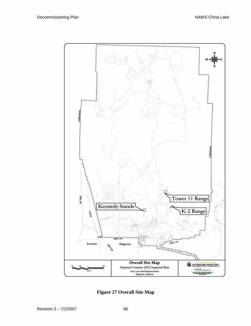
Decommissioning Plan NAWS China Lake
Revision 3 – 7/2/2007 90
Figure 27 Overall Site Map
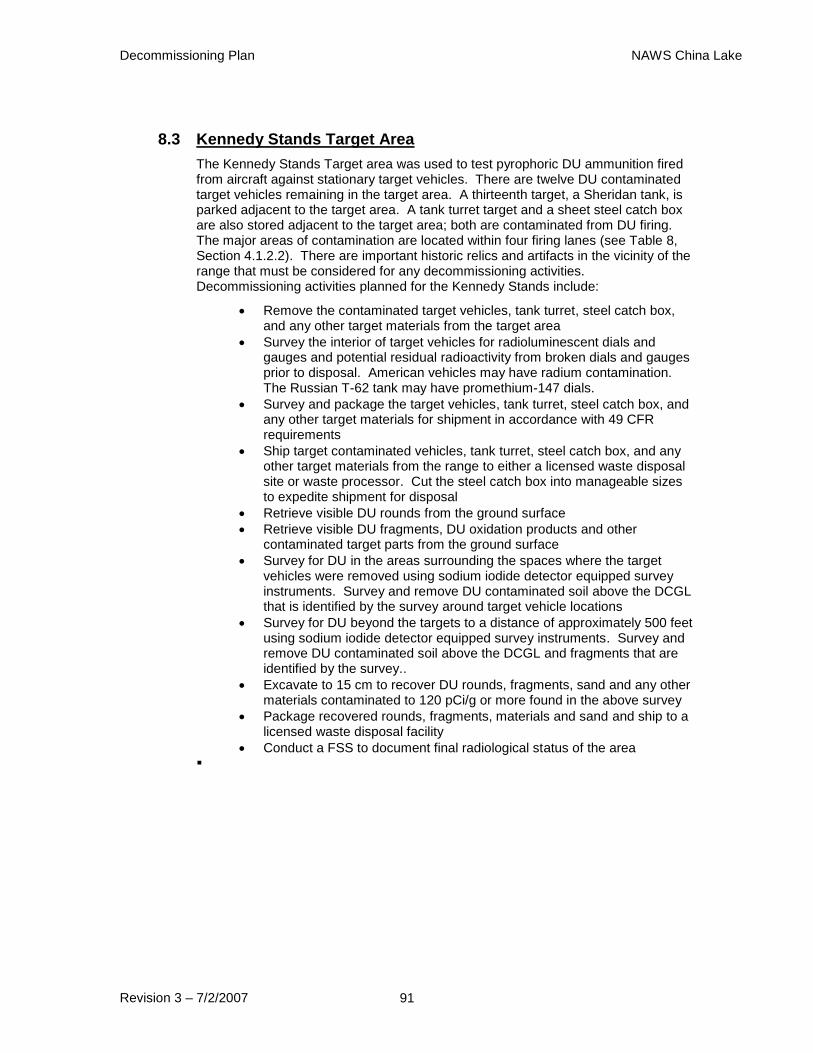
Decommissioning Plan NAWS China Lake
Revision 3 – 7/2/2007 91
8.3 Kennedy Stands Target Area
The Kennedy Stands Target area was used to test pyrophoric DU ammunition fired from aircraft against stationary target vehicles. There are twelve DU contaminated target vehicles remaining in the target area. A thirteenth target, a Sheridan tank, is parked adjacent to the target area. A tank turret target and a sheet steel catch box are also stored adjacent to the target area; both are contaminated from DU firing. The major areas of contamination are located within four firing lanes (see Table 8, Section 4.1.2.2). There are important historic relics and artifacts in the vicinity of the range that must be considered for any decommissioning activities. Decommissioning activities planned for the Kennedy Stands include:
Remove the contaminated target vehicles, tank turret, steel catch box, and any other target materials from the target area
Survey the interior of target vehicles for radioluminescent dials and gauges and potential residual radioactivity from broken dials and gauges prior to disposal. American vehicles may have radium contamination. The Russian T-62 tank may have promethium-147 dials.
Survey and package the target vehicles, tank turret, steel catch box, and any other target materials for shipment in accordance with 49 CFR requirements
Ship target contaminated vehicles, tank turret, steel catch box, and any other target materials from the range to either a licensed waste disposal site or waste processor. Cut the steel catch box into manageable sizes to expedite shipment for disposal
Retrieve visible DU rounds from the ground surface
Retrieve visible DU fragments, DU oxidation products and other contaminated target parts from the ground surface
Survey for DU in the areas surrounding the spaces where the target vehicles were removed using sodium iodide detector equipped survey instruments. Survey and remove DU contaminated soil above the DCGL that is identified by the survey around target vehicle locations
Survey for DU beyond the targets to a distance of approximately 500 feet using sodium iodide detector equipped survey instruments. Survey and remove DU contaminated soil above the DCGL and fragments that are identified by the survey..
Excavate to 15 cm to recover DU rounds, fragments, sand and any other materials contaminated to 120 pCi/g or more found in the above survey
Package recovered rounds, fragments, materials and sand and ship to a licensed waste disposal facility
Conduct a FSS to document final radiological status of the area

Decommissioning Plan NAWS China Lake
Revision 3 – 7/2/2007 92
Figure 28 Kennedy Stands Area Map

Decommissioning Plan NAWS China Lake
Revision 3 – 7/2/2007 93
8.4 K-2 Gunnery Range
The K-2 range is a 1,000 meter long static test range that was used for test firing 20 and 25 mm DU rounds and other small-caliber munitions, including high explosives. The majority of the fired rounds impacted an earthen berm at the target end of the range. DU rounds were fired at targets located at intermediate sites along the range, resulting in three areas of contaminated sand and soil in addition to the berm. DU rounds also impacted at intermediate sites along the range and skipped/ricocheted over the berm. Various target plates and vehicles were also used on this range. Only one vehicle remains at the site, and it is contaminated with radium, not DU. DU rounds can be found at or near the ground surface at the three intermediate locations along the length of this range. These locations have been posted with radioactive material warning rope and signs. The target end of the range is also protected by rope boundaries, including the berm which is contaminated with unexploded ordnance. Expended DU munitions are visible on the surface of the soil at K-2 and decommissioning activities are warranted. The decommissioning activities planned for the K-2 Range include:
Remove radium-contaminated truck carcass from the side of the range
Remove steel target plates that are at the site
Cut steel into manageable sizes and shapes for shipment
Survey and package the truck carcass and steel for shipment in accordance with 49 CFR requirements
Remediate and package contaminated soils in the three former target areas
Ship the truck and steel to either a licensed waste disposal site or a waste processor
Retrieve intact DU rounds, fragments and oxidation products detected by surface surveys (down to 15 cm bgs)
Remove the small mounds of sand/soil on the range where DU rounds were previously removed
Survey and package all removed material for disposal in accordance with the requirements of 49 CFR
Do nothing further with the earth berm. Levels of high explosive contamination make personnel access for DU recovery extremely hazardous
Conduct a FSS to document final radiological conditions of the site

Decommissioning Plan NAWS China Lake
Revision 3 – 7/2/2007 94
Figure 29 K-2 Range Map
Decommissioning Plan NAWS China Lake
Revision 3 – 7/2/2007 95
8.5 Tower 11 Target Area
This target area had the most extensive remediation activities of any of the
sites at NAWS. The granite in this area contains high levels of natural uranium, making
surveys for low levels of DU difficult (Ref. D-78, D-134). The contractor moved DU
contaminated equipment to a “parking” or storage area far to the east of the Tower 11
target area. Contamination was found in this parking area and subsequently removed by
the contractor. Follow-up surveys show the parking area was free of residual
contamination. Limited residual DU surface contamination remains at the Tower 11
target area. Decommissioning activities at Tower 11 will include:
Walk the area around the excavated target area to retrieve any DU fragments or DU oxides extant on the ground surface; remove sand/soil where the DU was removed
Containerize any removed materials for shipment to a low-level radioactive waste (LLRW) disposal facility
Survey with a sodium iodide detector equipped instrument to find DU contaminants.
Excavate and remove any DU fragments and contaminated sand/soil found which exceeds 120 pCi/g
Package any removed materials for shipment to a LLRW disposal facility
Ship waste for disposal
Decommissioning Plan NAWS China Lake
Revision 3 – 7/2/2007 96
Figure 30 Tower 11 Area Map
8.6 Contaminated Structures
None
Decommissioning Plan NAWS China Lake
Revision 3 – 7/2/2007 97
8.7 Contaminated Systems and Equipment
There are no known or expected contaminated systems at NAWS.
There are a total of twelve contaminated target vehicles and one contaminated M-47 Tank turret in the immediate target area. A contaminated M-41 Sheridan tank is behind and to the right of the immediate target area. The types of the twelve target vehicles are as follows: Four M-47 Tanks, two M-59 Armored Personnel Carriers, one M-113 Armored Personnel Carrier, one M-55 Self-Propelled Howitzer, one T-62 Tank, one LVTP-5 Landing Vehicle, one Amphibious Truck (DUCW), and one M-50 Ontos. (Figure 31), an aerial photograph of the area, shows the location of the target vehicles relative to each other.
In addition, other remnants of catch boxes and target plates may exist and will be disposed of as they are discovered during surveys. All contaminated equipment will be surveyed, loaded on transport vehicles, wrapped in appropriate containment materials to meet the shipping requirements of 49 CFR, and shipped off-site for further processing and disposal as contaminated waste at an approved waste disposal site.
Figure 31 Kennedy Stands Target Map
8.8 Schedules
Table 17 below is a summary of the schedule of planned decommissioning activities:
Table 17 Decommissioning Schedule

Decommissioning Plan NAWS China Lake
Revision 3 – 7/2/2007 98
K-2 Gunnery Range Effort in Weeks
12
Remove the radium-contaminated truck carcass from the side of the range
Remove the steel plates at the range
Survey and cut steel into manageable sizes and shapes for shipment
Survey and package the truck carcass and steel for shipment in accordance with 49CFR requirements
*Retrieve intact DU rounds, fragments and oxidation products detected by survey on the surface (to 15 cm bgs) of the ground
* Remove the small mounds of sand/soil on the range where the DU rounds were removed
Survey and package all removed material for disposal in accordance with the requirements of 49 CFR
(1)Ship the truck, steel and soils to waste disposal site or a waste processor (vehicles)
*Conduct a FSS to document final radiological conditions of the site
Kennedy Stands Target Area 22
*Improve/construct roads for target removal and access for waste removal
*Remove the contaminated target vehicles, tank turret and other target materials from the range
Survey and package the target vehicles and turret for shipment in accordance with 49CFR requirements
(1) Ship target vehicles and turret to either a waste disposal site or a waste processor which will take possession of the radioactive material
Cut steel catch box into manageable sizes to expedite shipment
Survey catch box parts to determine which are contaminated with DU to 3,000dpm/100 cm2 or greater
Package catch box parts that meet or exceed 3,000 dpm/100 cm2 for shipment in accordance with the requirements of 49 CFR
(1)Ship catch box parts to a waste disposal site or a waste processor which will take possession of the radioactive material in the parts
*Retrieve identifiable DU rounds, DU fragments, DU oxidation products and other contaminated target parts from the ground surface
*Survey for DU the areas where the target vehicles were removed to a depth of 15 cm around target vehicle locations
*Excavate to 15 cm to recover DU rounds, fragments, sand and any other materials contaminated to 14 pCi/g or more found in the above survey
Package recovered rounds, fragments, materials and sand for shipment to an approved waste disposal facility
Store waste materials on site until a sufficient amount is collected for shipment
(1) Ship waste to the waste disposal facility
*Conduct a FSS to document final radiological conditions of the site
Tower 11 Target Area 5
*Walk the area around the excavated target area to retrieve any DU fragments or DU oxides extant on the ground surface
*Survey with a sodium iodide detector equipped instrument to find DU contaminants to 15 cm below ground level
*Excavate and remove any DU and contaminated sand/soil found up to 15 cm below ground level
*Conduct a modified FSS to confirm final radiological conditions of the site
As the funds for decommissioning activities are not currently allocated, no firm schedule can be established at this time.
9.0 PROJECT MANAGEMENT AND ORGANIZATION
9.1 Decommissioning Management Organization
This project and all decommissioning activities will be performed under the
direction of the authorized representative of the holder of the NRMP for NAWS and
NAVSEADETRASO:
Mr. John Bradford
Naval Air Warfare Center
Building 00467
China Lake, CA 93555-6100
The majority of the work is expected to be performed by a decommissioning
contractor that is licensed by the Nuclear Regulatory Commission to perform
decommissioning activities. No entity has been contracted to perform the
decommissioning at this time.
9.2 Decommissioning Task Management
Decommissioning Plan NAWS China Lake
Revision 3 – 7/2/2007 99
Decommissioning activities will be managed by approved written procedures that address all operations performed in support of this project. Since these activities will be conducted with radioactive materials and in radiologically controlled areas, safety guidelines will be established in the Radiation Safety Plan (RSP) that will be generated by the contractor prior to commencing decommissioning activities. These guidelines will control all radiological work and will be implemented by the use of Radiation Work Permits (RWP).
RWPs will define the radiological working conditions, protective measures and administrative controls to be used for work activities in order to maintain personnel exposure ALARA. They will be reviewed and approved by the project Radiation Safety Manager (RSM) prior to implementation. The RSM will ensure that ambient radiation, surface radioactivity and airborne radioactivity surveys are performed as necessary to define and document the radiological conditions for each decommissioning task.
RWPs will describe the job to be performed, reference the applicable procedure(s) for the job, outline tasks with significant radiological hazard, define protective clothing and equipment to be used, and identify personnel monitoring requirements. In addition to specifying any radiological hazards to workers, they will also identify other hazards in the work area, such as unexploded ordnance, and reference the precautions to be taken to minimize risk to workers.
While procedures and RWPs provide administrative tools to define and manage decommissioning work activities, a qualified and competent workforce is essential to safely and efficiently doing the work. The sections below describe the requirements for this workforce.
9.3 Decommissioning Management Positions and Qualifications
The following management positions will be filled by qualified personnel to direct the decommissioning activities:
9.3.1 Project Manager
The Project Manager (PM) will have overall responsibility for ensuring the work associated with this DP is done safely, efficiently and within budget. His primary duties will include, but not be limited to:
Establish and execute program administrative matters and controls, program-related policy matters, and program levels of authority, responsibility and communication
Establish and maintain a records management system to verify that project documents are controlled. Project documents include, but are not limited to: correspondence, procedures, drawings, specifications, contract documents, document changes, inspection records, corrective action documents, and personnel records
Ensure appropriate personnel have been assigned to the project team and that they are qualified to perform the tasks to which they are assigned
Review and approve project procedures
Overall management of site personnel, including implementing necessary disciplinary actions

Decommissioning Plan NAWS China Lake
Revision 3 – 7/2/2007 100
The Project Manager will have a minimum of 5-years experience in conducting environmental remediation/restoration efforts, primarily with radioactive material
Act as point of contact with the Navy with regard to contract matters
9.3.2 Radiation Safety Manager
The project Radiation Safety Manager is responsible for the overall management of the project radiation safety program and maintenance of personnel radiation exposure ALARA. The management responsibility for these matters includes, but is not limited to:
Manage the radiation protection program for the project
Approve and implement the RSP for the project
Coordinate with the PM and Safety and Health Manager (SHM) in developing a Health and Safety Plan (HASP) for the project
Ensure compliance with applicable regulations concerning the radiological protection of project personnel
Ensure compliance with applicable regulations concerning the handling and transportation of radioactive materials, particularly radioactive waste
Provide training for project personnel who may be exposed to ionizing radiation and other hazards
Coordinate with the SHM for field implementation of the HASP
Review the results of surveys, sampling, and environmental monitoring to verify their correctness and to identify trends and potential for exposure to personnel or the environment
Identify other potential radiological and safety hazards and modify the RSP and/or HASP to protect personnel against these hazards
Specify proper PPE and resources necessary to implement the RSP and HASP
Conduct daily safety briefings (tailgate meetings)Observe work in progress to confirm adherence to radiation safety practices and procedures
Develop additional health and safety procedures as required
Assist in the investigation of accidents/incidents and near misses
Terminate unsafe work and ensure corrective actions are in place prior to permitting resumption
Assist in QA audits and assessments as required
The Radiation Safety Manager will have a minimum of 5-years experience in conducting environmental remediation/restoration efforts, primarily with radioactive material
Report on a daily basis to the Project Manager
9.3.3 Health and Safety Manager
The project Health and Safety Manager (HSM) is responsible for ensuring the project is completed safely. His responsibilities include, but are not limited to:
Ensure that the HASP complies with all applicable local, state and Federal regulatory requirements

Decommissioning Plan NAWS China Lake
Revision 3 – 7/2/2007 101
If necessary, modify the HASP to adjust for on-site conditions that affect safety
Evaluate and authorize any changes to the HASP
Coordinate with the RSM and PM for field implementation of the HASP
Conduct safety training, including participation in daily briefings
Evaluate the effectiveness of engineering and administrative controls, including PPE requirements and environmental safety issues
Assist in QA audits and assessments as required
The Health and Safety Manager will have a minimum of 5-years experience in conducting environmental remediation/restoration efforts, primarily with radioactive material
Report on a daily basis to the Project Manager and Corporate Health and Safety Manager
9.3.4 Project Engineer
The Project Engineer will serve as the technical lead for the project and provide Quality Assurance oversight. His responsibilities will include, but not be limited to:
Provide technical assistance and peer review for all phases of the project
Prepare, review and implement the Quality Assurance Plan
Conduct on-site technical management for the project and health and safety support as required
Provide technical assistance for the handling and shipment of radioactive waste, particularly for those large items that will be disposed of as part of this DP
Participate in daily safety briefings as required
Conduct training as required
Assist in QA audits and assessments as required
Implement the Corrective Action Reporting (CAR) program
The Project Engineer will have a minimum of 5-years experience in conducting environmental remediation/restoration efforts
Report on a daily basis to the Project Manager
9.3.5 Personnel Assigned to the Project
Each person assigned to this project is responsible for his/her health and safety, including radiological safety. Accepting accountability for his/her individual safety as well as the safety of all others on the project is the paramount responsibility of each project employee. Personnel will be hired on the basis of their qualification to perform their assigned tasks. Each member of the project team is responsible to:
Read and become familiar with the project HASP and RSP
Participate and cooperate in all assigned training activities
Perform only tasks they can do safely and competently and for which they have been trained
Notify the project HSM of any special medical conditions or any prescription and/or non-prescription medication they may be

Decommissioning Plan NAWS China Lake
Revision 3 – 7/2/2007 102
taking that could impair their judgment or work performance or create an unsafe working condition
Prevent the spread of contamination
Maintain their individual exposure to radiation ALARA
Report any unsafe act or working condition to project management as soon as possible
Stop work if conditions are immediately dangerous to human health
Be aware of the archaeological sensitivity of work areas, especially at the Kennedy Stands
Not disturb or remove any archaeological or historic artifacts
Practice good housekeeping everywhere on this project
Immediately report any injury to project management
Comply with the requirements of the HASP and RSP and properly use any PPE required for the work being performed
Obey instructions of NAWS range and safety personnel in regard to the presence of unexploded ordnance on the ranges
Be aware of the effects of heat in the desert environment: stay hydrated, apply sun block and wear appropriate clothing
Must have the training mandated by 29 CFR 1910.120 (40 hours plus 3 days on-site experience). Supervisors shall have 8 hours of additional supervisory training. The contractor shall provide written evidence of current Occupational Safety and Health Administration training for each person performing work and a corporate certification that each person is medically capable of working on a hazardous waste site.
9.3.6 Radiation Safety Officer
The Radiation Safety Officer will be responsible for organizing, administering, and directing the radiation protection program at the NAWS during the decommissioning activities, including radiation safety and environmental health. The Radiation Safety Officer's responsibilities will include:
Initiating or approving the radiation safety and health aspects of NAWS procedures, standards, and rules and ensuring the program is adequately operated
Participating in design and decommissioning plan reviews where potential radiation exposure and safety could be affected
Developing methods for keeping radiation exposures ALARA for workers and all facility personnel
Conducting surveillance programs and investigations to ensure that occupational radiation exposures are below specified limits and ALARA
Identifying locations, operations, and conditions that have the potential for causing significant exposures to radiation and initiating actions to minimize or eliminate unnecessary exposures.
Assisting the Decommissioning Project Manager in ensuring that the QA program is effectively implemented.
The Radiation Safety Officer will have the authority to enforce safe performance of NAWS decommissioning activities and to shut down operations or activities because of either safety or environmental issues, if immediate corrective action is not taken, until a technical review has been

Decommissioning Plan NAWS China Lake
Revision 3 – 7/2/2007 103
conducted. Resumption of work will require DON Decommissioning Project Manager or DON Construction Manager approval following completion of reviews and implementation of any required corrective actions.
The Radiation Safety Officer will have specific training in the radiation health sciences and will have experience in applying this knowledge to managing a radiation protection program. Minimum qualifications for the Radiation Safety Officer are a bachelor's degree in physical science or biological science or the equivalent, with a minimum of two years of applied health physics experience in a program with radiation safety considerations similar to those for the NAWS decommissioning project.
9.4 Decontamination And Decommissioning Documents and Guides
The Decommissioning Plan for NAWS has been written using the guidance and format specified in NUREG-1757, Consolidated NMSS
Decommissioning Guidance. The radiological criteria for license termination to allow
unrestricted use will be as set forth in 10 CFR Part 20, Subpart E, "Radiological Criteria
for License Termination," and will follow the NRC guidance in Draft Regulatory Guide
DG-4006, "Demonstrating Compliance with the Radiological Criteria for License
Termination" (NRC 1998a). NAWS will use these main documents for its
decommissioning effort. NAWS will also use the other regulations, regulatory guides,
and standards listed below.
Code of Federal Regulations:
10 CFR Part 19 "Notices, Instructions and Reports to Workers; Inspections"
10 CFR Part 20 "Standards for Protection Against Radiation"
10 CFR Part 30 "Rules of General Applicability to Domestic Licensing of Byproduct Material" "
10 CFR Part 50 "Domestic Licensing of Production and Utilization Facilities"
10 CFR Part 51 "Licensing and Regulatory Policy and Procedures for Environmental Protection”
10 CFR Part 61 "Licensing Requirements for Land Disposal of Radioactive Waste"
10 CFR Part "Packaging of Radioactive Material for Transport and Transportation of Radioactive Material under Certain Conditions"
10 CFR Part 140 "Financial Protection Requirements and Indemnity Agreements"
29 CFR Part 1910 "Occupational Safety and Health Standards"
29 CFR Part 1926 "Occupational Safety and Health Standards for Construction"
49 CFR Parts 170-199"Department of Transportation Hazardous Materials Regulations
NRC Regulatory Guides:
DG-4006 "Demonstrating Compliance with the Radiological Criteria for License Termination"
1.86 "Termination of Operating Licenses for Nuclear Reactors"
8.2 "Guide for Administrative Practices in Radiation Monitoring"
Decommissioning Plan NAWS China Lake
Revision 3 – 7/2/2007 104
8.4 "Direct-Reading and Indirect-Reading Pocket Dosimeters"
8.7 "Occupational Radiation Exposure Records Systems"
8.9 "Acceptable Concepts, Models, Equations and Assumptions for a Bioassay Program"
8.10 "Operating Philosophy for Maintaining Occupational Radiation Exposure As Low As Is Reasonably Achievable"
8.13 "Instruction Concerning Prenatal Radiation Exposure"
8.15 "Acceptable Programs for Respiratory Protection"
Regulatory Guidance and Documents:
NUREG-1505 "A Nonparametric Statistical Methodology for the Design and Analysis of Final Status Decommissioning Surveys"
NUREG-1507 "Minimum Detectable Concentrations with Typical Radiation Survey Instruments for Various Contaminants and Field Conditions"
NUREG-1549 "Using Decision Methods for Dose Assessment to Comply with Radiological Criteria for License Termination, Draft"
NUREG-1575 "Multi-Agency Radiation Survey and Site Investigation Manual (MARSSIM)"
NUREG-1727 “NMSS Decommissioning Standard Review Plan”
NUREG-1757 “Consolidated NMSS Decommissioning Guidance”

Decommissioning Plan NAWS China Lake
Revision 3 – 7/2/2007 105
9.5 Training
Personnel assigned to this project will be trained in regard to the types and magnitudes of radiological, industrial safety, personal hygiene, and physical hazards they may encounter while working and/or visiting the site. Training will also be provided for the conditions unique to NAWS. The following sections describe training for this project.
9.5.1 Visitor Training
Visitors to the ranges will be escorted at all times. They will not normally be permitted to enter radiologically controlled areas. Training will consist of a general site/project orientation that discusses:
Radiological conditions
Site-specific safety and health conditions
9.5.2 General Employee Training
General Employee Training (GET) will be administered to all employees working on this project. GET will include the following:
Discussion of the project’s goals
Discussion of the working environment at NAWS, including environmental hazards, security and sensitive cultural and natural resources in the project work areas
Description of the forms of DU contamination at NAWS and its potential health hazards
General employee safety
Quality assurance
Worker rights and responsibilities
Locations of project RSP and HASP
Identification of radiological postings and barriers
Protective equipment and procedures
Emergency procedures
How to contact project management representatives and radiation safety staff
9.5.3 Radiation Worker Training
In addition to the GET described above, those employees who will be working with radioactive materials or in radiologically controlled areas will be required to have extended Radiation Worker Training (RWT) before being permitted to work at NAWS. This training will include:
Radioactivity and radioactive decay
Forms and characteristics of ionizing radiation
Manmade and natural radiation sources
Biological effects of exposure to radiation
Risks associated with occupational radiation exposure
Considerations with respect to exposure of women of reproductive age
Dose equivalent limits and determinations
Modes of exposure (external and internal)Basic protective measures (time, distance, shielding)Specific methods of maintaining exposure ALARA
Radiation survey instruments, including types, calibration, use and limitations

Decommissioning Plan NAWS China Lake
Revision 3 – 7/2/2007 106
Radiation monitoring program and procedures
Contamination control, including administrative controls, PPE, engineering controls and workplace design
Personnel and equipment decontamination
Emergency procedures
UXO awareness
Warning labels, signs and barriers
Responsibilities of workers and management vis-à-vis radiation safety
RWT will consist of a classroom lecture and procedure review, a practical demonstration of basic radiological safety principles, question and answer period, a handout and a written test. A passing grade of 80 percent is required. A challenge examination may be administered in lieu of the full RWT for those previously trained or demonstrating sufficient radiological work experience.
Any employee who will need radiation monitoring dosimetry will be required to provide a current NRC Form 4 to project management prior to obtaining the dosimetry.
9.5.4 Tailgate Safety Training
A safety briefing will be conducted prior to the beginning of each daily work shift, whenever significant changes in site working conditions or job scope occur, or whenever new personnel arrive at the job site. All personnel will be required to attend. Health and safety procedures and issues for the day, any unique hazards associated with a work activity, and a review of any significant topic from previous activities will be presented at this meeting. The topics discussed will be recorded and attendees will be required to sign an attendance list to confirm they received the information discussed at the briefing. Tailgate training documentation will be included in the decommissioning records.
9.5.5 Training Records
Training documentation will be included in the decommissioning record. The information included in these records will include:
Project identification
Type of training conducted
Date, time and place of training
Topics discussed
Signatures of attendees
In addition to the training and records generated from the training, the project contractor will post copies of pertinent notices to employees required by local, state and Federal law, including, but not limited to, NRC Form 3 Notice to Employees, in a conspicuous location at the work site. A copy of the NAWS NRMP will also be made available at the site.
9.6 CONTRACTOR SUPPORT
This section discusses the functions that contractors will perform as part of the
decommissioning effort. The contractor will perform and support the actual decommissioning
activities. This contractor will be the Decommissioning Contractor. The Navy will select all
contractors through established procurement procedures and standards requiring a rigorous
source evaluation and review process. The review and evaluation specifications will define
scope and method of selection and criteria for contractor qualifications, experience, and

Decommissioning Plan NAWS China Lake
Revision 3 – 7/2/2007 107
reputation. The actual selection of all contractors has not yet occurred. Schedules and specific
tasks to be performed by contractors will be planned in advance and detailed work procedures
will be developed. Prerequisites, such as safety, health, and environmental precautions and
protective clothing requirements, will be defined in writing before work is started. All
contractors will adhere to NAWS procedures delineating the policies and administrative
guidelines applicable to the NAWS decommissioning project, and work will be performed in
accordance with NAWS safety and environmental requirements.
The Navy currently envisions that the Decommissioning Contractor will provide all
decontamination and dismantling services and related support activities during the
decommissioning. The Decommissioning Contractor will perform the decommissioning
operations and supervise and schedule day-to-day decommissioning activities. NAWS personnel
will ensure that all contractor activities are safely performed and comply with 10 CFR Part 20
and other applicable regulations, license conditions, the decommissioning order issued by NRC,
and the decommissioning plan.
The Decommissioning Contractor will be responsible for ensuring that
decommissioning contractor staff are trained in performing work in radiation areas; setting up
work areas and the equipment and services necessary for safely accomplishing the work; scoping
and preparing detailed procedures; providing sequencing and scheduling; and processing,
packaging, shipping, and disposing of radioactive materials. The Decommissioning Contractor
will have complete responsibility for ensuring the safety and health of their employees and for
complying with Occupational Safety and Health Administration (OSHA) and NRC requirements.
All these efforts will be subject to the review, approval, and authority of the N Decommissioning
Project Manager and the Radiation Safety Officer to ensure compliance with NRC requirements,
license conditions, and NAWS safety and health requirements.
While the decommissioning contractor’s efforts will be focused on surveying and removing materials from the ranges, compliance with applicable regulations, health and safety, and project management, specialty services may be required from a subcontractor with the requisite skills, experience, and/or facilities. Such services could include packaging and shipment of radioactive waste and laboratory analyses.
Each subcontractor will provide a task manager and, if necessary, a health and safety and/or quality control contact who will report to the task manager. At all times, the decommissioning contractor will be responsible for the scope, quality and timeliness of services provided by all subcontractors. The RSM will verify that subcontractor personnel are adequately informed of the conditions and hazards at the work site, preventive measures in place, and the procedures associated with each work task for which the subcontractor is responsible. The PM and RSM will verify that subcontractor personnel perform their decommissioning work in accordance with all licensing commitments and regulatory requirements.
NOTE: A Memorandum of Understanding (MOU) will be executed with the facility RSO and decommissioning contractor delineating each organizations responsibility.
10.0 HEALTH AND SAFETY PROGRAM DURING DECOMMISSIONING
Decommissioning activities will be conducted in a manner that protects workers, the environment and the public. The overall policy for radiological protection during decommissioning activities is to maintain human and environmental exposure to known or suspected radioactive and/or hazardous

Decommissioning Plan NAWS China Lake
Revision 3 – 7/2/2007 108
materials by following the Radiation Safety Plan. The RSP will consist of standard operating procedures (SOPs) which include both administrative (AP) and operating (OP) procedures. APs will include procedures to control record retention, Radiation Work Permits, reporting radiological conditions adverse to quality, radiological compliance assessments and audits, ALARA, dosimetry program and radiation worker training. Additional administrative and operational controls will be used by the decommissioning contractor to guide the conduct of all relevant decommissioning activities. The RSP will comply with the requirements of 10 CFR parts 10 and 20. Copies of the procedures used for the decommissioning will be maintained on site at NAWS for reference and regulatory review. The decommissioning contractor will provide a workplace where site employees, visitors and contractors are adequately protected from all hazards, including those associated with exposure to radiation and radioactive materials, as well as any unexploded ordnance or other physical and chemical hazards that may exist on the ranges where decommissioning activities take place. While expected exposures to individual workers associated with the planned work are low, all radiation exposures are assumed to entail some risk to personnel. ALARA requirements will be communicated to all personnel at the outset of their employment on this project. All individuals will be required to understand their responsibilities to maintain their radiation exposure ALARA. Methods to control exposures will be reviewed during initial site-specific training and during work review, or “tailgate”, meetings. Monitoring and surveillance information will be summarized and reviewed by the workforce on a planned and periodic basis. A site-specific health and safety plan (HASP) will be developed and applied to describe the practices to be employed to reduce employee exposure to radioactive and other hazardous materials. The HASP will remain in effect during all on-site decommissioning activities. The decommissioning contractor will maintain documentation to demonstrate the effectiveness of the health and safety program. The project Health and Safety Manager (HSM), or his/her designee, operating under the supervision of the RSM will monitor on-site health and safety. The RSM, or a designee will conduct tailgate safety meetings, implement surveillance and individual monitoring programs, perform release surveys for personnel and equipment during decommissioning operations, and maintain all health and safety records generated during the decommissioning.
10.1 Radiation Safety Controls and Monitoring for Workers
The RSP will be implemented to control exposure to ionizing radiation through
approved SOPs. The SOPs reference and provide instructions to ensure activities at NAWS
comply with the requirements of applicable federal regulations, including those of 10CFR parts
19 and 20. The primary task of the RSP is to ensure no personnel exceed the occupational
exposure limits of 10 CFR 20 and that total effective dose equivalent (TEDE) is ALARA.
Radioactive materials and sources of radioactivity will be controlled such that radiation
exposures to workers do not exceed the limits specified in 10 CFR 20, Subpart C.
Radiation safety personnel assigned to the project will conduct radiation and
contamination surveys as required to control the work to maintain personnel doses ALARA.
Surveys will be conducted using survey instruments and methods suitable for the nature and
range of radiological hazards anticipated, primarily the presence of depleted uranium and its
oxidation products. Equipment and instruments will be calibrated and operationally tested prior
to use in accordance with approved procedures. Routine surveys of work areas, equipment and
radioactive waste material will be conducted at specified frequencies to ensure that
contamination and radiation levels in unrestricted areas do not exceed applicable license, federal,
state or site limits. Surveys will also be performed whenever work activities create the potential
to impact radiological conditions.
Decommissioning Plan NAWS China Lake
Revision 3 – 7/2/2007 109
The need for individual monitoring for internal and external exposures will be
determined and documented prior to the start of work based on applicable survey data. Potential
exposures to personnel working on the NAWS decommissioning project include direct contact
with radioactive materials (e.g., ingestion exposure pathway) and airborne dusts that may contain
DU oxidation products (inhalation exposure pathway). Radiation protection personnel will
perform routine monitoring for radioactive contamination to minimize the spread of
contamination, and consequently, the risk from ingestion of radioactive materials.
While it is only a remote possibility for this decommissioning project, internal and
external radiation monitoring shall be conducted continuously when it is likely that any
individual may receive ten percent or more of the annual dose limits of 10 CFR 20. Baseline
urinalysis for the presence of uranium will be conducted for radiation workers at the beginning
and termination of their employment on this project. If the possibility of an airborne activity in
excess of ten percent of a derived air concentration (DAC) is likely or is detected by air
sampling, the RSM will evaluate the need for any additional bioassay monitoring. Workers who
have received radiation exposure prior to employment on this project will be required to provide
records of their radiation exposure history or names and addresses of previous employers and
locations where they received radiation exposure. Copies of these records will be maintained in
the individual workers’ personnel exposure file by the decommissioning contractor. The
decommissioning contractor will provide each radiation worker with a written record of his/her
exposure during this project as required by 10 CFR 20.
10.2 Air Monitoring Program
While it is not expected that airborne radioactivity will be generated by the
decommissioning work in this plan, the decommissioning contractor will perform airborne
radioactivity sampling surveys in accordance with approved sampling procedures to ensure
potential airborne radioactivity is measured. Air samples will be collected under known
conditions (e.g., sample time, air flow rate) using calibrated air samplers. Samplers shall be
calibrated prior to their first use on this project and following any repair or modification.
Both breathing zone and general area air samples will be collected when there is the
potential for generating airborne radioactivity from decommissioning activities. Breathing zone
sampling will be the preferred method of measuring individual intake of radioactive material.
Samples will be collected at each affected individual worker’s breathing zone at work locations
where airborne activity is likely to be generated. General area samples will be collected as
necessary from work areas, especially downwind of any excavation and other areas with the
greatest likelihood of the presence of radioactively contaminated airborne dust. The RSM will
determine the appropriate equipment to be used to perform airborne sampling surveys. The type
of sampling specified will determine the appropriate sample collection medium required to
collect any potential contaminants. The frequency at which sampling media will be changed will

Decommissioning Plan NAWS China Lake
Revision 3 – 7/2/2007 110
be determined based on the radiological and physical conditions of the work location, worker
stay times at the work site, and the type of air sampling performed.
Baseline air sampling will be done at each work location prior to initiating work in
order to document background airborne activity levels. Air sampling will be done during initial
excavations of DU contaminated sand/soil to determine if the excavation generates airborne
radioactivity. The RSM will determine the need for additional air sampling during
decommissioning activities based on the results of preliminary sampling and after any significant
changes in operating conditions. Sampling durations will be determined based on required
action levels, counting instrument sensitivities and other conditions as warranted.
Initial air sample counting will be done as soon as practicable after sample collection
and then after the sample has been stored for at least 24 hours to determine if short-lived activity
is a concern. Subsequent samples may be counted either after collection or after a 24-hour decay
period, depending on the contribution of short-lived activity. Sample count times will be
sufficient to achieve required minimum detectable concentration (MDC) goals for uranium.
Sample results will be compared with the DAC for uranium (or any other radionuclides that may
be detected) and appropriate protective measures determined by the RSM or his/her designee
based on the DAC information. Breathing zone samples may be collected by lapel air samplers
or by grab samples in the workers’ breathing zones. If breathing zone activity concentrations
exceed ten percent of a DAC, the RSM will determine appropriate protective measures for the
worker(s). Protective measures taken and the worker dose from the airborne activity will be
documented in individual personnel exposure records.
Since the primary nuclide of concern is uranium, air samples will be counted for
alpha activity. If gross alpha activity is significantly in excess of (three times or more greater
than) background, air samples will be counted by an accredited analytical laboratory to
determine the presence of uranium isotopes.
10.3 Respiratory Protection Program
The policy of this decommissioning plan is to maintain personnel exposures to
known or suspected airborne radioactive and/or hazardous materials ALARA. Respiratory
protection will be included as an element of this policy. While it is not expected that airborne
contamination will be generated during decommissioning activities, respiratory protection for
individual workers will be maintained by the application of practicable engineering controls,
such as using decontamination processes that minimize the generation of airborne particulates.
The use of respirators is not expected during decommissioning work.
Protection of workers through the use of respirators is not considered to be a routine
operation. Given the nature of the DU to be removed—primarily in the form of complete
Decommissioning Plan NAWS China Lake
Revision 3 – 7/2/2007 111
projectile rounds, solid fragments and oxide forms that do not lend themselves to becoming
airborne—the possibility of generating respirable airborne particulates is remote. Given the
environmental conditions of the work sites at NAWS and the inclination of workers wearing
respirators to work more slowly than those not wearing respirators, the use of respirators is not
desirable from the standpoint of maintaining TEDE ALARA during normal planned work
evolutions. It is unlikely, but unforeseen conditions that could create an emergency situation
requiring the use of respirators to protect personnel could occur. Emergency conditions are
unplanned events characterized by the need for rapid and aggressive actions to prevent or
mitigate the effects of rapidly deteriorating conditions. The use of respirators during such events
is often a reasonable substitute for engineering controls that must be assumed to be nonfunctional
or ineffective. Respirators will be available at the work site should such an emergency condition
arise. Respirator use, maintenance and storage will be controlled by approved procedures to
preserve respirator effectiveness.
10.4 Internal and External Exposure Determination and Control
Any required internal dose assessment will be done through the analysis of breathing
zone air sampling and the evaluation of bioassay results, primarily the results of urinalysis for
uranium. These analyses will be performed in accordance with approved procedures. Any
worker’s committed effective dose equivalent (CEDE) will be limited to less than ten percent of
the annual allowable limit on intake (ALI) as specified in Table I of Appendix B to 10 CFR 20,
providing the TEDE to the individual is maintained ALARA. The RSM will determine the
validity of any bioassay and air sampling results prior to their inclusion in the internal dose
assessment process.
External radiation exposure will be assessed using appropriate survey
instrumentation. If the RSM determines an individual is likely to receive more than ten percent
of an annual dose limit as defined in 10 CFR 20, personnel dosimetry will be issued to measure
the dose in accordance with approved procedures. Dosimetry may consist of self-reading pocket
dosimeters and/or thermoluminescent dosimeters. The dosimetry device(s) used will be worn to
measure dose to the whole body or to an extremity as needed. Whole body dosimetry will
normally be worn on the upper torso or as directed by the RSM. Personnel are responsible to
wear dosimetry as directed by the RSM. If a personal dosimetry device is lost, misplaced or
indicates an anomalous or off-scale reading, the employee will be required to report the event to
their supervisor or a radiation control staff member immediately.
All reasonable effort will be made to ensure the ionizing radiation exposure to an
unborn child is kept to the lowest practicable level as defined in 10 CFR 20.1208. While she is
not required to do so, once a female employee determines she is pregnant, she is encouraged to
notify her supervisor and the RSM of her pregnancy in writing. Appropriate measures will be
implemented to limit exposure to the unborn fetus to less than 500 mrem for the term of the
pregnancy and below 50 mrem per month in any month following the declaration of pregnancy.
Decommissioning Plan NAWS China Lake
Revision 3 – 7/2/2007 112
10.5 Exposure, Radiation and Contamination Control Program
Since the goal of this DP is to remove and dispose of as much of the DU remaining
on the ranges as practicable, every effort will be taken to ensure the DU is removed carefully to
minimize the potential for spreading contamination beyond the ranges.
Routine surveys will be taken during the DU removal operations to ensure
radioactive contamination is not spread. Survey frequencies will be determined by the radiation
protection staff and any spread of contamination detected during a survey will be carefully
removed. Surveys will normally be planned in advance, and each survey will be documented on
an appropriate map or survey record. The target vehicles and steel sheeting that will be removed
as part of the decommissioning will also be surveyed to determine the removable contamination
levels on each. They will be wrapped in an appropriate containment material (e.g., plastic shrink
wrap) prior to their being removed from the ranges where they are currently stored. These target
surveys also will be documented on appropriate survey records. Areas where DU contaminated
materials are stored prior to shipment to a licensed waste disposal facility will be surveyed
periodically to ensure no DU contamination contaminates the surface of the storage location.
The surface may also be covered with plastic sheeting or other impermeable material to contain
potential leakage.
To ensure no radioactive material inadvertently is removed from the work sites,
personnel will wear anti-contamination clothing appropriate to the task they are performing with
consideration for personal comfort in light of the high desert environmental conditions at
NAWS. Those engaged in removal of the DU projectiles and ground contamination will
normally wear a minimum of shoe covers and gloves. Plastic arm and leg gaiters may also be
worn. It will probably not be desirable to dress workers in full anti-contamination coveralls, but
such clothing will be available should the RSM determine its use justified. The use of any other
specialized protective clothing will be determined by the RSM on a case-by-case basis. Anti-
contamination clothing will be removed in a controlled manner upon personnel exit from
contaminated work sites. The clothing will be placed into approved containers and shipped off-
site for disposal with other waste products.
Personnel will be required to perform whole body frisks using calibrated hand-held
friskers and probes suitable for detection of DU. Equipment removed from contaminated work
areas will also be frisked and, if necessary, decontaminated. Records of equipment release
surveys will also be maintained on standardized forms and maps in the permanent files for the
decommissioning project. Release criteria will be consistent with those defined in the RSP. In
the event sealed sources are used by the decommissioning contractor, the RSM will verify the
conditions of the license regulating the use of such sources, including verification of operator
training and the frequency of wipe tests for source leakage.
10.5.1 Exposure Control
Decommissioning Plan NAWS China Lake
Revision 3 – 7/2/2007 113
Application of engineering, administrative and personnel protection provisions will control and minimize personnel exposure to radioactive materials. The priority of application will be in descending order in respect to the descriptions below.
Engineering controls will be used, whenever practicable, to minimize or prevent the spread of uncontained radioactive material. Engineering controls will be predominantly composed of containment, isolation, ventilation and contamination.
Administrative controls will be used to control working conditions and work practices. Administrative controls will predominantly include:
Access control: Routine access to work areas will be limited to personnel necessary to accomplish tasks or activities. Access will also be controlled with respect to training and use of specified personnel protective equipment (PPE).
Postings and barriers: Postings will be used to inform personnel of relevant hazards or conditions and associated access requirements. Barriers may be used to prevent unauthorized access.
Procedures: Written and approved procedures may be used to describe specific radiation protection requirements for those tasks involving radioactive materials.
Radiation Work Permits (RWPs): RWPs will be used to define activities to be performed where radioactive materials are involved. They will describe specific or special worker protection and dosimetry requirements for activities involving radioactive materials. RWPs may also be used in conjunction with written procedures.
Contamination control: Action levels and limits for radiation and contamination surveys, described in the RSP, will be used to control the levels of radioactivity on equipment and areas.
Personnel protective equipment (PPE) will be used to control personnel exposure to radioactivity when administrative controls are not sufficient and engineering controls are not practicable. PPE may include, but not be limited to, head covering, eye protection, respiratory protection, impervious outerwear (coveralls), gloves, and/or protective shoes or shoe covers. PPE will be identified on the RWP for the task(s) for which it is required.
10.5.2 Radiation Surveys
The primary purposes of radiation surveys to be performed during the decommissioning are to locate the DU that is to be removed and to ensure contamination is not spread. Appropriate survey instrumentation for these tasks and acceptable techniques for its use will be described in approved decommissioning procedures. Surveys will be performed to describe the types of radiation detected, to proximate locations of the sources of radiation and to ensure the DU is removed to an acceptable residual radioactivity level. Work area surveys will be done to ensure workers are not exposed to radiation hazards and to maintain individual exposures ALARA. Surveys will also be done to support shipment of radioactive waste and frisking of individual workers.
Surveys will be performed to detect alpha, beta and gamma radiations. The types of surveys to be performed include:
Decommissioning Plan NAWS China Lake
Revision 3 – 7/2/2007 114
Contamination measurements: The presence of removable DU contamination from surfaces (such as those of target vehicles) will be measured by wiping a prescribed area (usually 100 cm
2) with cloth, paper or some other medium capable
of collecting a representative sample of surface radioactivity. Swipes will be checked with an appropriate survey instrument and/or counted in appropriate calibrated counting equipment for alpha, beta or gamma radioactivity as necessary to measure the level of DU contamination.
Radiation: Exposure rate measurements will be performed using an ion chamber or an instrument equipped with a thallium-activated sodium iodide detector. Measurements will be made at prescribed distances from the sources of radioactivity and may also be made at contact with the source.
Personnel measurements: Personnel will be frisked with an appropriate instrument and detector upon exiting a controlled work zone or when deemed necessary by radiation protection personnel.
Action levels: Action levels will be established to inform personnel when a situation requires evaluation so corrective actions can be taken. Action levels are set so that corrective actions can be effective before a regulatory limit is exceeded. Exceeding an action level requires an investigation to determine the root cause and to apply appropriate preventive and/or corrective actions. The investigation and documentation of an event must be completed commensurate with the significance of the condition(s) and severity of the event.
10.5.3 Instrumentation Program
Instruments used for radiation detection and measurement will be operated, calibrated and controlled in accordance with approved procedures. Calibrations will be performed by a certified calibration laboratory. Radiation detection instruments will be calibrated in a manner and frequency per license and manufacturer requirements and after each repair that would affect the accuracy of the instrument. Only personnel with documented records of training will be permitted to use survey and counting instruments to record valid radiological data. Each instrument will have a valid calibration sticker attached to allow the operator to verify the instrument is within current calibration prior to use. Survey instruments will be visually inspected, battery checked and source check prior to use. Radiation survey equipment and instrumentation suitable for detecting and quantifying radiation hazards to workers and the public will be present on-site throughout decommissioning activities. The selection of instruments, detectors and counting equipment will be based on the radiological characteristics of depleted uranium in the varied forms expected to be found at NAWS. Equipment and instrumentation selection will also take into account the environmental working conditions, contamination levels, and source terms encountered during decommissioning work. In all cases, the instrumentation program will be consistent with the requirements of the RSP.
10.5.4 Health Physics Audits, Inspections and Record-Keeping Program
The RSP is the governing radiological control document for this project. It is subject to an annual audit and periodic inspections to determine if radiological operations are being conducted in accordance with regulations, license conditions and written procedures.
An audit of the radiological safety program shall be conducted annually by the RSM or his/her designee. The designee shall not be a member of the contractor organization or any other party whose participation in the audit could be interpreted as a conflict of interest. The audit will consider the functional areas of the radiation

Decommissioning Plan NAWS China Lake
Revision 3 – 7/2/2007 115
protection program: i.e., Radiation Work Permits, radiation protection procedures, radiological surveys, air monitoring and respiratory protection, the ALARA program, individual and area monitoring results, access controls, and training. The audit shall be conducted in accordance with a specific audit plan developed by the auditor. A written report of the audit’s scope and findings will be generated within 30 days of the completion of the audit. The report shall be distributed to the appropriate site and project management and shall be available for review by the project work crew. A written corrective action plan shall be prepared to address issues of non-compliance. All corrective actions will be tracked to completion. Once corrective actions have been completed, a written closure report shall be distributed to site and project management.
Periodic assessments of the quality of the radiation protection program will be performed by the RSM or a qualified independent observer to ensure the program is being implemented adequately. These assessments need not be as formal as the audit program, but they should be documented and areas of non-compliance discovered during the assessment shall be treated with the same level of attention to correcting deficiencies as if they were discovered during the formal audit process.
The health and safety staff shall conduct periodic inspections and routine reviews of decommissioning operations and activities as a normal component of their work functions. Inspections shall normally be completed to the standards of pre-established checklists. Checklists should be developed independently for differing periods; e.g., daily, weekly, monthly. The checklist should normally include routine procedural requirements. The results of the routine inspections shall be maintained in a tracking log by the RSM. The log should include a description of planned corrective actions for any anomalous conditions and the date of completion of corrective actions.
Follow-up inspections of all corrective actions shall be taken and recorded by the RSM or his/her designee to ensure the corrective actions have been properly implemented and to measure their effectiveness.
10.5.5 Personnel Records
A personnel file will be created and maintained for each worker assigned duties involving radioactive materials for this project. These files will include:
A record of radiation exposure received by the individual during any prior employment involving radioactive material. This file will be developed by requesting exposure information from the employee and his/her previous employer(s).
Records of training received prior to or during employment on this decommissioning project, including the results of any tests administered.
A record of the results of personal dosimetry measurements for dose received by the individual during the course of this decommissioning project.
Any report(s) detailing the loss and/or malfunction of a dosimetry device and the results of the subsequent investigation of such loss or malfunction.
Any record(s) of the exposure of an individual to an airborne radioactivity concentration in excess of ten percent of a DAC value for DU, including air sample results, bioassay sampling results, and calculation of any internal dose and/or uptake of radioactive material.
Records of any respirator fit tests and/or practical exercises demonstrating understanding of the proper use of PPE.
Reports of any incident of personal contamination above the limits specified in the RSP, including decontamination efforts and effectiveness and follow-up corrective action(s) and/or training.

Decommissioning Plan NAWS China Lake
Revision 3 – 7/2/2007 116
Personnel records will be maintained indefinitely and personnel may review their files and/or request copies of information in their files at any time.
10.5.6 Radiation and Contamination Records
Records of radiation and contamination survey generated during site surveys, remediation and decommissioning activities and any characterization and release surveys will be retained by the decommissioning contractor. Copies of the records will be supplied to NAWS management.
10.5.7 Waste Disposal Records
Radiation and contamination survey records, shipping manifests and certifications generated for shipment of DU contaminated waste to a licensed disposal facility will be retained by the decommissioning contractor. Copies of these records will be provided to NAWS management.
11.0 ENVIRONMENTAL MONITORING PROGRAM
The decommissioning contractor and the U.S. Navy will be committed to maintaining
exposure to ionizing radiation to workers, the public and the environment ALARA and will conduct all decommissioning work in a manner that supports this commitment. All decommissioning activities will comply with applicable regulatory requirements, including those designed to protect the environment from the harmful effects of radiation.
11.1 Effluent and Waste Monitoring Program
Given the physical characteristics of depleted uranium in the forms found on the
ranges at NAWS (full projectiles, projectile fragments and uranium oxides of relatively low
quantity and large particle size), the density of the uranium, and the large distances from the
ranges where decommissioning will occur to the site boundaries (measured in miles), coupled
with the high natural uranium background at NAWS and its surroundings, there is no credible
scenario where concentrations of radionuclides in site effluents will be increased by
decommissioning activities. Since radioactive material is being physically removed during
decommissioning, there will be a net positive effect on any potential radioactive contaminants in
these effluents.
The primary effluent stream for radioactive contaminant transport during
decommissioning is expected to be airborne dust from the movement of vehicles, any excavation
work, and handling of radioactive waste. The quantity of dust generated by these activities is
expected to be minor compared to that generated by the prevailing winds that are normal for
NAWS. Since most of the DU on and in the sand/soil at NAWS is in the form of intact
penetrators and fragments, and given the great density of DU, the probability of generating any
Decommissioning Plan NAWS China Lake
Revision 3 – 7/2/2007 117
airborne contaminants from DU removal operations is remote. The quantity of oxides of DU that
are on or in the sand/soil is small compared to the volume of the penetrators and fragments and
the sand/soil at the ranges where decommissioning activities will take place, making the
likelihood of generating levels of airborne activity approaching or in excess of regulatory limits
at the site boundary nearly impossible.
To establish that no airborne effluents will be generated as a result of
decommissioning activities, baseline background air samples will be taken prior to
commencement of work at each range where decommissioning activities will occur. These, and
any subsequent air samples, will be obtained in the downwind direction from where any dust is
expected to be generated to ensure the samples represent potential release pathways. The RSM
will assess the air sampling program to ensure the samples are obtained in the appropriate
downwind direction and that samples obtained represent any potential airborne radioactive
effluents. The need for further air sampling will be based on the results of background and
preliminary sampling. The RSM and radiation protection staff will evaluate working and
environmental conditions to determine the need for further air sampling to ensure no radioactive
material is inadvertently released to the environment.
No liquid effluents are anticipated to be generated.
11.2 Effluent Control Program
As discussed in the previous paragraphs, decommissioning activities are not likely to
generate airborne or liquid effluents of regulatory concern. Dust generated during
decommissioning activities will be the most likely source for creating airborne contaminants.
Since dust will also make decommissioning work uncomfortable for the workers, every effort
will be made to ensure dust generation from decommissioning activities is minimized. Any
material removed from the ranges and staged for shipment will be wrapped or covered to
minimize the possibility of releasing radioactive material to the environment.
If air monitoring results indicate airborne contamination exceeding 10% of the
appropriate DAC level, the RSM will implement corrective measures to mitigate the
contamination.
12.0 RADIOACTIVE WASTE MANAGEMENT PROGRAM
Only the solid radioactive waste stream requires consideration for this project; no liquid waste will be generated. Solid wastes will be collected, packaged, stored, and shipped for disposal in accordance with the guidelines below.
Decommissioning Plan NAWS China Lake
Revision 3 – 7/2/2007 118
12.1 Solid Radioactive Waste (Radwaste)
Solid radioactive waste from this decommissioning project will consist of
contaminated vehicles, metal scrap and DU rounds and fragments with a small amount of
contaminated sand and soil. Miscellaneous wastes consisting of contaminated protective
clothing and monitoring and sampling supplies, such as swipe papers and filter samples counted
to determine radioactivity concentrations, will also be generated.
The larger waste products, primarily the contaminated target vehicles and plates, will
be wrapped and packaged in materials that comply with the appropriate shipping regulations of
49CFR and sent to a disposal facility or waste processor who will take possession of the
radioactive materials with which they are contaminated.
General radioactive waste will be collected and stored in closed containers in an
approved location. The waste will be packaged into approved shipping containers that have been
lined with plastic or an equivalent material. Shipping containers will be monitored for
compliance with the applicable shipping regulations of 49CFR and transported to a licensed
radioactive waste disposal facility, most probably Envirocare of Utah, Incorporated.
The estimated total volume of solid radioactive waste that will be generated and
disposed of during the proposed decommissioning activities is 17,300 cubic feet.
12.2 Liquid Radiation Waste
No surface water exists at the ranges to be decommissioned and decommissioning
work will not be performed during periods of precipitation, therefore no liquid radioactive waste
will be generated during decommissioning operations.
13.0 QUALITY ASSURANCE PROGRAM
Activities outlined in this decommissioning plan will be performed in accordance with approved written procedures and/or protocols to ensure consistent, repeatable results and that work is conducted safely and in compliance with all applicable regulatory requirements. Procedures may include, but not be limited to, personnel training requirements, proper operation and calibration of instruments, contamination control measures, collecting, storing and preparing waste for shipment, quality control (QC) requirements, personnel dosimetry and PPE use.
In order to maintain high standards of performance and to ensure compliance with
applicable regulations, a quality assurance (QA) program will be implemented for this project based on the following criteria.
13.1 Organization
Project management, including the RSM, will be trained and qualified to appreciate
the unique conditions at NAWS, including, but not limited to: the site environment, the presence
of unexploded ordnance on the ranges, range access requirements, and worker safety in a desert
working environment. Management will also be expected to understand the procedures
governing work on this project and the regulations and procedures controlling the retrieval and
disposition of the depleted uranium.
Decommissioning Plan NAWS China Lake
Revision 3 – 7/2/2007 119
Only qualified and trained personnel will be permitted to perform activities to
complete this decommissioning plan. Technicians will be trained (with training documented) in
the use of the radiation survey, sampling and counting equipment. All personnel will be trained
in the technical, quality control, and health and safety aspects of their work. They will be
required to demonstrate understanding of and proficiency in the use of the procedures and
equipment with which they will accomplish their assigned tasks.
Frequent tailgate safety meetings will be used to provide supplemental training and
information about the progress of the project. These meetings, and other supplementary training
as may be needed through the duration of the project, will also provide a forum for field
personnel to identify any potential safety or quality concerns that need to be addressed by project
management. All personnel will be encouraged to communicate their concerns openly and
without fear of retribution. Safety meeting and other training notes and attendance sheets will be
maintained on site and in the permanent project files. Project personnel will be permitted to
review these documents as they deem necessary.
Personnel responsible for implementing the QA program and for verifying that
activities affecting quality are performed correctly will have sufficient authority, unfettered
access to work areas, and organizational freedom to:
Identify quality concerns
Ensure decommissioning activities are controlled or curtailed until proper
resolution of a non-conformance or deficiency has occurred
Initiate, recommend, or provide solutions to quality concerns or defects through
site or corporate management
Verify that solutions to quality issues have been implemented and are effective
A non-production member of the decommissioning team will be assigned as QA
officer for this project. This individual will have free access to project and upper level
management to ensure that quality issues are addressed and resolved at the appropriate level.
The QA officer may authorize or delegate others to implement specific elements of the QA
program or to act as quality control representatives for field and laboratory work. Project
employees will be empowered to identify quality issues to quality assurance/quality control
personnel and to all levels of project management with an expectation that their concerns will be
acknowledged and addressed with requisite respect and timeliness.
13.2 Document Control
Data will be recorded and documented in a formal data management system.
Radiation and contamination survey maps will designate the location(s) being surveyed, the date
of the survey, the identity of the surveyor and sufficient information about surveying and
counting instrumentation used for the survey to ensure traceability of data. Methods for

Decommissioning Plan NAWS China Lake
Revision 3 – 7/2/2007 120
identifying survey and sample points, such as Global Positioning System (GPS) instrumentation,
will be used as necessary to ensure repeatable data points are identified. Personnel responsible
for creating and managing data will ensure that chain-of-custody (COC) and data management
procedures are followed, particularly for those data related to Final Status Surveys (FSS) and
waste shipments. Procedures to collect, handle, store and ship samples will be approved by
project management. These procedures will follow established protocols for these kinds of
activities.
Radiation and contamination surveys and analytical results will be documented.
Documentation will be legible, correctly recorded and reviewed by management to ensure its
accuracy and consistency. Survey and sampling results will be recorded in a tabular format. All
documentation for this project will be subject to verification by program audits and assessments.
Ledger type Logs of Events will be maintained for decommissioning activities.
These logs may be created at various organizational levels depending on the tasks performed.
The responsibility for preparing these logs and the assignment of personnel to the task will be at
the direction of the Project Manager.
The Project Manager will record project evolution on a daily basis. This daily log
will be of sufficient detail to recreate a general tableau of the project after the project is
completed. The PM will submit a weekly summation of project-related events to corporate
management for forwarding to the appropriate government representatives to apprise them of
project progress, status and any significant concerns or problems encountered.
Changes to this decommissioning plan and any significant supporting plans, such as
the quality assurance plan, or protocols will be submitted to the appropriate Navy representatives
for review and approval before they are implemented. At a minimum, all records associated with
this project will be maintained until the license/NRMP is terminated.
13.3 Control of Measuring and Test Equipment
The project work plans will define which detection, surveying and counting
instrumentation will be required to complete this decommissioning plan. Only instrumentation
approved by the project health physicist will be used to collect radiological data. The project
RSM is responsible for ensuring that individuals are trained and qualified to use radiation
detection instrumentation and other equipment, and that instrumentation meets required detection
sensitivities. Instrumentation shall be operated in accordance with approved written procedures
and/or manufacturer’s instruction manuals. These procedures and manuals will provide guidance
on the proper use and limitations of the instruments to field personnel.

Decommissioning Plan NAWS China Lake
Revision 3 – 7/2/2007 121
Instruments will have current calibration and maintenance records kept on site for
review and inspection. At a minimum, the records will include:
Name of the instrument/equipment
Instrument/equipment model and serial number
Manufacturer
Date of calibration
Calibration due date
Any quality control records associated with counting instruments (e.g., daily
background checks, chi-square test verification)
Instrumentation will be maintained and calibrated to manufacturer’s specifications to
ensure that required traceability, sensitivity, accuracy and precision are maintained. All
instruments will have a current calibration, from a facility possessing a current NRC or
Agreement State licenses for performing calibrations using National Institute of Standards
(NIST) traceable radiation sources.
Prior to daily use, instruments used for this project will be QC checked by comparing
instrument response to a benchmark response. Prior to the commencement of field
measurements, site reference locations will be selected for performance of these QC checks.
Subsequent checks will be performed at these locations. QC source checks for counting
instruments will consist of a one-minute integrated count, or other count time as designated by
the project health physicist or his/her designee, with the source in a reproducible geometry at the
reference location. Prior to the start of initial counting, this procedure will be repeated at least
ten times to establish an average instrument response. Background readings will also be
established and checked in accordance with this protocol. Instrumentation should also be
inspected for physical damage, current calibration and erroneous readings in accordance with
applicable procedures. Instruments that do not meet the specified requirements of calibration,
inspection or response check will be removed from operation until the deficiency(ies) is/are
corrected.
Additional quality control checks may be implemented for the instruments and
equipment used for this project based on experience gained from careful evaluation of the
working conditions encountered. These checks will be reviewed and approved by the project
RSM and PM and incorporated into the appropriate instrument operating procedures.
Procedures for calibration, maintenance, accountability, operation and quality control
of radiation detection instruments implement the guidelines established in American National
Standard Institute (ANSI) standard ANSI N323-1978 and ANSI N42.17A-1989.
Decommissioning Plan NAWS China Lake
Revision 3 – 7/2/2007 122
13.4 Corrective Action
The project QA officer has overall responsibility for reporting all procedure and
contract deviations and violations reported during the course of work to the appropriate level of
management. The RSM and PM will determine if a deficiency requires work to be stopped or if
notification to the appropriate Navy representative is required.
A deficiency or nonconforming condition is documented on a form, such as a
Corrective Action Request (CAR) or its equivalent that allows straightforward reporting of the
condition and those actions necessary to correct it. The form is initiated by any individual who
recognizes and reports a nonconforming condition. The form should provide a detailed
description of the nonconforming condition and reference the affected documents that apply.
The form is submitted to the project QA officer who will review it for completeness, legibility,
and that a satisfactory description of the problem is being reported. The CAR will be logged into
an administrative system to track its progress through the corrective action process. The CAR is
then passed to the manager responsible for determining the root cause of the nonconformance
and implementing corrective action(s).
The individual(s) responsible for identifying the root cause(s) of and correcting the
nonconformance will document their actions on the appropriate sections of the CAR and forward
it to the QA officer.
Upon completion of corrective actions, the QA officer will review the CAR and
verify that root cause determination is adequate and that the corrective actions address the
original concern and provide an effective remedy to prevent recurrence of the nonconformance.
If all is satisfactory, the QA officer will accept the response and close the CAR. The CAR will
be reviewed with the individual who initiated it and, if he approves the corrective actions, he will
sign the document. Should the initiator not approve of the corrective actions, the CAR will
remain open until additional actions are taken and documented to address his/her concerns.
These actions will either be addressed on an additional CAR or on an addendum to the original.
In either case, the CAR cannot be closed until the initiator and responsible managers have signed
it to demonstrate their concurrence with the documented actions.
After all corrective actions have been completed and all approval signatures and
dates affixed to the CAR, the closed CAR will be added to the documentation for the project and
its closing documented in the CAR log.
13.5 Quality Assurance Records
All quality related documents will be monitored by appropriate members of project
management with a final check by the QA officer. Data reduction, QC review and reporting of
laboratory results will be the responsibility of the analytical laboratory. Data reduction includes
all automated and manual processes for reducing or organizing raw data generated by the
laboratory. The laboratory will generate a data package for each set of analyses that will include
copies of the raw data and any other information needed to check and recalculate the analytical
results. After a data package is completed by the laboratory, the analytical results and pertinent
QC data will be entered into a database where it will serve among the basic reference material
for data validation and for use as data for the project. Concentrations of soil activity will be
calculated from these data.
Decommissioning Plan NAWS China Lake
Revision 3 – 7/2/2007 123
Generation, handling, calculations, evaluation and reporting of final radiological
survey results will be specified in project procedures. Included in these procedures will be a
system for data review and validation to ensure consistency, thoroughness and acceptability of
the resultant data. A random selection of data points will be chosen to be examined to determine
compliance with QA requirements to verify the quality of the results. Any rejected data or data
omissions identified during data validation will be evaluated to determine their impact on the
project. Corrective actions may be taken to ensure the quality of the survey results. These
corrective actions may include, but not be limited to, resampling and reanalyzing, evaluating and
amending sampling and analytical procedures, and accepting data while acknowledging the level
of uncertainty in the results.
One of the most important aspects of sample and data management is to ensure the
integrity of a sample is maintained. That is that there is an accurate record of sample collection,
transport, analysis and disposal. Proper control of the sampling process will ensure that samples
are neither lost nor tampered with and that a sample analyzed in the counting laboratory is
actually and verifiably the sample taken from a specific location in the field. A method of
controlling this sampling, analysis and reporting process is to establish a chain of custody (CoC)
procedure for each sample. Such a procedure will be included in the project procedures. A
standard form for tracing the CoC will be created and used for sample control during this project.
Any individual responsible for sample collection will initiate a CoC using this standard form. A
copy of this form will accompany each sample through transport, analysis and disposal of the
sample. If there is a breach of the CoC process or if evidence of tampering with any sample is
detected, the nonconformance will be documented and corrected using the corrective action
process described above. Project management will ensure that any deliberate malfeasance in
sample handling is treated as a severe breach of project integrity.
13.6 Audits and Surveillances
Periodic audits and assessments will be performed by the decommissioning project
manager, other project management and designated auditors and assessors to verify that
decommissioning activities comply with approved procedures and other requirements of the
project QA plan, such as scope, status, accuracy and compliance and to evaluate the overall
adequacy of the QA program. Project senior management and the QA officer will verify that
qualified personnel are assigned to perform audits to ensure the applicable procedures are
properly implemented. Audits will be conducted on at least a quarterly basis while assessments
may be performed at any time. Audits will be done using written guidelines or checklists while
assessments may be less formal. External audits and assessments may be performed at the
discretion of project management.
Audit and assessment results will be reported to senior project management in
writing and actions taken to resolve any identified deficiencies will be tracked and documented.
The corrective action process described above may be used to formally track and correct
Decommissioning Plan NAWS China Lake
Revision 3 – 7/2/2007 124
deficiencies. Audit and assessment information will be included in the decommissioning record
for the site.
14.0 FACILITY RADIATION SURVEYS
Various radiological surveys of sites at NAWS that may have been impacted by DU have been done over the years; two of the more heavily investigated locations are the range at Building 10520 (old Building 52) and Site 6 (T Range burning pit). The results of these surveys are included in this plan (Refs. D-141-146). With the exception of those performed at the Kennedy Stands Target Area, K-2 Gunnery Range and Tower 11 Target Area, characterization surveys have not been done at most other NAWS areas potentially impacted by the use of DU.
14.1 Characterization Surveys
Characterization surveys have been performed and identified DU contamination at the Kennedy Stands range, K-2 Gunnery Range and Tower 11 Target Area. The DU consists of complete projectile rounds, fragments of DU rounds, and uranium oxide from the corrosion of these projectiles and fragments in and on the surface sand/soil. These surveys and their results are included in the references to this plan. They will be used for planning and completing the activities of this DP and are summarized in sections 4.1.2, 4.1.3, and 4.1.4 of this DP.
14.1.2 Gamma Scan Surveys
The survey methodology combined a commercial Differential Global Positioning System (DGPS) and data management system using commercially available radiation detection equipment. The Ludlum Model 2350 Data Logger instruments were used to record the count rate for the location acquired during scan surveys into an internal memory buffer.
The gamma detectors used were Ludlum Model 44-10, consisting of a 2" x 2"sodium iodide (NaI) crystal (approximately 6 cubic inches in size). These detect gamma rays with energies from 60keV to 3MeV. This energy range includes gamma rays emitted by Uranium-238 and its decay products.
When a gamma ray is detected, the detector (and associated meter electronics) registers one count. Counts are electronically integrated, and recorded in units of counts per minute (cpm.) The accumulated data points were transferred to lap top computers in the field and loaded into spread sheets for analysis.
14.1.3 Detection Sensitivity
The default detection sensitivity for the detector/instrument configuration described above is 56 pCi/g, as stated in Table 6.7 of MARSSIM. Site specific sensitivity will be determined once project activities are initiated and current background levels can be used.
14.1.4 Soil Sample Analysis
Soil samples were analyzed by gamma spectroscopy analysis. Gamma activities were determined for U-238 using Th-234 and Pa-234m, the decay daughters of U-238. Any other peaks found, such as Cs-137, were also reported.
Decommissioning Plan NAWS China Lake
Revision 3 – 7/2/2007 125
14.2 Remedial Action Support Surveys
Radiological support surveys and sampling will be performed during the course of decommissioning activities to ensure all planned removal actions are completed.
14.3 Final Status Survey Design and Release Criteria
The final status survey design will be provided upon acceptance of the methodologies and release criteria presented in this DP. The DCGL for release of the ranges is proposed in the RESRAD run results for 120 pCi/g of DU. This concentration results in a TEDE, under the scenarios presented, of approximately 21 mrem/y which is ALARA when compared to the NRC’s unrestricted release criteria of 25 mrem/y TEDE.
120 pCi/g is clearly detectable using the proposed survey instrumentation, is
protective of human and environmental health under the proposed scenarios, and avoids the
substantial risks of subsurface excavation and removal of UXO in support of removal actions.
15.0 RESTRICTED USE CRITERIA
Since no restricted use release is planned, and the fact the Navy will maintain control
of the areas for the foreseeable future no discussions on restricted release are applicable for this
DP.
16.0 FINANCIAL ASSURANCE
Financial assurance and funding of activities supporting the decommissioning and radiological release of sites at NAWS China Lake are provided through the U. S. Government, specifically the Department of Defense, and are dependent on congressional appropriation.

Decommissioning Plan NAWS China Lake
Revision 3 – 7/2/2007 126
REFERENCES
The reference documents can be found at the following link: http://www.sagecon.com/China%20Lake/Index.htm
Username: nwt
Password: nwt1565
Documents
Ref. # Date Title
D-01 48-11-05 Memo: Electronic Instrumentation on Long Track
D-02 49-03-03 Memo: NOTS High Speed Track Test Facility Correspondence to 3 March
1949
D-03 49-05-25 Memo: Ballistics Range Facility (SNORT)
D-04 49-06-16 Memo: Project SNORT; Proposed Utilization of
D-05 53-06-08 Memo: Future Programs (re nuclear work at Inyokern)
D-06 53-07-01 Memo: Preliminary Proposal for Site 300
D-07 53-10-05 Memo: Small Weapons Program Assistance
D-08 55-01-06 List: Summary of Important Events in the History of NOTS
D-09 57-09-04 Memo: Establishment of New Division in Weapons Development
Department
D-10 57-10-16 Memo: Wisconsin Film Badge Report Cover Letter
D-11 57-12-06 Memo: Weapons Development Department; request for management
approval for realignment and title change
D-12 57-12-17 Memo: US NOTS, China Lake; Weapons Development Department,
Nuclear Weapons Evaluation Division; approval for establishment of
D-13 58-09-18 Memo: Current and future requirements for fission products
D-14 58-10-13 Memo: Projected requirements for fission products
D-15 58-12-24 Memo: Monitoring and Evaluating Radiological Contamination of Ranges
at NOTS
D-16 59-02-16 Memo: Trip Report to NOTS
D-17 59-09-04 Memo: US Naval Ordnance Test Station, China Lake, CA; request for
redesignation of
D-18 59-10-02 Memo: US Naval Ordnance Test Station, China Lake, CA; Request for
redesignation of
D-19 59-11-05 Memo: Health and Safety Measures for AEC-DOD test program, Project
TN2-8054
D-20 60-07 Newsletter: Reynolds Newsletter Article Working with Radiation
D-21 60-08-09 Memo: Radioactive Material Licenses Issued by AEC (Byproduct)
D-22 60-08-19 Memo: Byproduct Material License 4-1757-2
D-23 62-04-16 Memo: Visit to NOTS (Trip Report; mentions Tuballoy)
D-24 62-06-13 Memo: NOTS-DASA Structure Tests
D-25 62-07-11 Memo: Source Materials License-Info on DU Incineration
D-26 63-01-24 Memo: Additional Information for SUB-683
D-27 63-01 Report: History of Air Force Atomic Cloud Sampling

Decommissioning Plan NAWS China Lake
Revision 3 – 7/2/2007 127
D-28 63-04-30 Memo: Proposed Inspection; postponement of (Kennedy visit)
Documents (cont’d)
Ref. # Date Title
D-29 63-09-24 Memo: Powdered Uranium Cautions
D-30 63-10-02 Memo: AEC License SUB-683
D-31 63-12-17 Memo: Differential Thermal Analysis runs on Samples Containing DU
D-32 63-10 Memo: Summary Propulsion Development Dept Safety Procedures for
DU and Th
D-33 64-02-18 Memo: Monitoring Results of DU and Natural Thorium Project
D-34 64-04-16 Memo: Monitoring Results of DU and Natural Thorium Project
D-35 64-07-01 Memo: Comparison of Results of Alpha Contamination Analysis between
NOTS and NRDL
D-36 64-07-10 Memo: Monitoring Results of DU and Natural Thorium Project
D-37 64 to 65 Lab Record: HP data for sample mixing and tests
D-38 65-03-30 Memo: Recommend Approval of Request for Amendment of SUB-683
D-39 65-03 to 04 Memo: Amendment Requests for SUB-683 Issued 63-01
D-40 65-04-02 Memo: License Non-compliance Letter
D-41 65-11-04 Memo: Report of Uranium Fire
D-42 65-11-22 Memo: Fire in Dock 63B on 10-29-65
D-43 69-05-19 Memo: Machining 20 mm DU Rounds
D-44 69-06-13 Memo: Request for Amendment to SUB 683 DU rods
D-45 69-06-19 Memo: Procedures for firing DU projectiles at CT-1 and K2 Ranges
D-46 69-12-12 Memo: DU, unsafe handling of
D-47 71-05-27 Memo: Buried Munitions, Chemicals and Radioactive Materials
D-48 72-89 Field Notes: Field Notes on DU Testing and Other Radiological Issues
D-49 75-02-19 Memo: MK 149 Projectile Tests
D-50 75-07 to 76-02 Field Notes: Handwritten Notes re SNORT DU Tests
D-51 75-09-18 Procedure: Debris Recovery Procedures for DLD (Dynamic Lethality
Demonstration)
D-52 76-03-03 Memo: Request for Amendment to SUB-683
D-53 76-03-17 Memo: Request for Amendment to SUB-683
D-54 76-09-23 Memo: NRC Letter re Application to Amend SUB-683
D-55 77-01-11 Memo: Amendment of License SUB-683
D-56 77-10-18 Memo: Radioactive Material at NWC
D-57 78-05-10 Memo: Training Class on Working with DU
D-58 79-06 Report: Aberdeen Transonic Range Environment Radiological Monitoring Report
1973-1978
Decommissioning Plan NAWS China Lake
Revision 3 – 7/2/2007 128
Ref. # Date Title
D-59 79-11-06 Memo: 120-mm Projectiles with DU Penetrators request for concurrence
in firing
D-60 80-04-01 Request: Work Request to fill mine shafts
D-61 80-04-25 Memo: Past activities that my relate to leukopenia
D-62 80-06-20 Memo: Continuation of Early Range
D-63 80-06-30 Report: AWC 120mm Test
D-64 80-07-21 Memo: Early Range History re Leukopenia
D-65 80-08-07 Report: 120mm Environmental Study
D-66 80-08-22 Memo: Monitoring Program for 120-mm Gun Test
D-67 80-08-25 Notes: Meeting Minutes and Sketches re 120-mm Catch Box
D-68 80-09-08 Memo: Meeting of 80-08-25 on 120-mm Gun Project
D-69 80-10-16 Memo: GAU- 12 Gun Effectiveness Test
D-70 80-12-09 Memo: Safety Procedures for GAU-12 Tests of 10 through 19 December
at NWC
D-71 80-12-22 Memo: Past activities on Center re Leukopenia
D-72 80-12-29 Memo: Burning of DU meeting with NWC China Lake Personnel
D-73 80-12 Table: Summary of Test Events at Kennedy Stands
D-74 80-12-? Memo: Possible Hazardous Waste Sites
D-75 80 Presentation: Presentation for 120-mm DU Test Program
D-76 81-01-05 Memo: Early Use of DU and Thorium in the Ordnance Systems
Department
D-77 81-01-12 Memo: Natural Trace Thorium Background
D-78 81-01-12 Memo: Natural Trace Uranium Background
D-79 81-01-19 Memo: Meeting on Work with DU and Th
D-80 81-01-20 Memo: Declassification of Application for SUB-683
D-81 81-01-20 Memo: Past activities on Center re leukopenia
D-82 81-01-21 Field Notes: Handwritten notes re mine visits
D-83 81-01-26 Field Notes: Proposed entry into mine shafts
D-84 81-01-27 Memo: Mine Rescue Group Investigation of Center Mine
D-85 81-02-05 Field Notes: Handwritten notes on mine inspections
D-86 81-04-08 Memo: NRC Inspection with Notices of Violation
D-87 81-04-14 Memo: Letter of appreciation for mine shaft entries
D-88 81-04-17 Memo: NRC Inspection of 03-25 & 26-81 report on items of non-
compliance
D-89 81-04-17 Memo: Reports of Depleted Uranium
D-90 81-04-29 Memo: Environmental Aspects of DU
D-91 81-05-11 Memo: Environmental clearance for mine shaft closures
D-92 81-05-21 Field Notes: Observations of closing operations of two mine shafts

Decommissioning Plan NAWS China Lake
Revision 3 – 7/2/2007 129
Documents (cont’d)
Ref. # Date Title
D-93 81-08-27 Memo: Results of GAU-12-U Tests of May 1981
D-94 82-02 Report: Proposed Modification to Tower 11 Gun Range Target Catch Box
D-95 82-11-08 Memo: Trip Report (Includes DU at SNORT)
D-96 82-11-19 Memo: Record of Telecon with Tom Vendetti of Aerojet on DU
Processing at Firing Bunkers
D-97 83-01-21 Field Notes: Depleted Uranium Target Plates
D-98 83-04-15 Memo: Renewal of SUB-683
D-99 88-08-23 Specification: Specifications for subcaliber 20 mm rounds WS20591B
D-100 83-09-29 Memo: Statement of DU Inventory
D-101 83-11-17 Memo: Storage and Disposal of DU Waste from Weapons Tests at NWC
D-102 84-01-20 Memo: Visit to NAVWPNCEN by B. Ayers of AWC re DU
D-103 84-02-13 Memo: Ionizing Radiation Safety; Weapons containing DU; requirements
for safety personnel
D-104 84-04-24 Memo: AWC Letter re China Lake DU Air Sampling
D-105 84-05-11 Memo: NRC Request for Additional Info re SUB-683
D-106 84-05-29 Memo: Renewal of SUB-683
D-107 84-05-31 Memo: RASO Relocation
D-108 84-05-31 Memo: Review of plan for processing and disposal of DU sands
D-109 84-07-07 Memo: Rad controls for stowing DU ammunition
D-110 84-07-09 Memo: Additional info for renewal of SUB-683
D-110 84-07-09 Memo: Additional info for renewal of SUB-683
D-111 84-07-31 Receipt: DU from A-7 Crash Site
D-112 84-09-10 Memo: 25mm Armor Piercing Incendiary Rounds; radiation safety for
D-113 84-09-11 Memo: Statement of DU Inventory
D-114 84-09-18 Memo: SUB-683 Amendment 7
D-115 84 Memo: Additional information for renewal of NRC License SUB-683
D-116 85-03-05 Memo: AWC DU Air Sample Results
D-117 85-09-17 Memo: Statement of Depleted Uranium Inventory
D-118 86-01-07 Memo: DU Clean-up at Tower 11 Gun Range
D-119 87-06-18 Certification: Conversion of SUB-683 to NRMP
D-120 88-03-03 Memo: Rad Safe - AV8B Test Range - Draft Report
D-121 88-03-18 Memo: Range Safety Response to Draft report 1988
D-122 88-07-28 Memo: Rad Exposure of Personnel at Kennedy Stands pre-1988
D-123 89-02-28 Application: NRMP 06530-L1NP application; DU included

Decommissioning Plan NAWS China Lake
Revision 3 – 7/2/2007 130
Documents (cont’d)
Ref. # Date Title
D-124 89-04-03 Summary: Chronological sequence for NRC License SUB-683
D-125 89-05-18 Memo: GAU-12 Gun Tests (U)
D-126 89-90 Logbook: Record of DU Firings at G6
D-127 90-01-09 Memo: Pattern of Unmeasured and Uninformed Exposure of Personnel to
Radium and Uranium Dust
D-128 90-02-22 Memo: DU Fouled Areas
D-129 90-04-23 Memo: Range Survey for AEC Shapes
D-130 90-07-24 Memo: Ionizing Radiation Exposure of Personnel
D-131 91-07-02 Memo: Radioactive Materials located at NAVWPNCEN
D-132 92-01 Report: Tower 11 Clean Up Strategies-1992
D-133 92-03-02 List: NAVWPNCEN Ionizing Radiation Inventory
D-134 92 Memo: Ionizing Radiation at NAWS
D-135 93-11-04 Webpage: Original Rocketeer article on China Lake history
D-136 97-01-20 Report: Lockheed Final Status Survey Report
D-137 97-06-23 Memo: Tower 11 Cleanup Reports
D-138 97-12-18 Instruction: Storage of Depleted Uranium
D-139 99-04-30 Drawing: K-2 Coordinates
D-140 2000-12-22 Memo: NRSC Alternate Decommissioning Schedule for G-6 Range with
supporting documents 2000-12-15, 2000-12-20
D-141 2001-09-22 Memo: Analysis of China Lake Soil Samples
D-142 2001-11-15 Report: Tetra Tech Removal Site Evaluation for Site 6 CLAK0921A
D-143 2001-11-15 Report: Tetra Tech Removal Site Evaluation for Site 6 Technical
Appendices CLAK0921B
D-144 2001-11-15 Report: Tetra Tech Removal Site Evaluation for Site 6 Technical
Appendices CLAK0921C
D-145 2001-11-15 Report: Tetra Tech Removal Site Evaluation for Site 6 Technical
Appendices CLAK0921D
D-146 2001-11-15 Report: Tetra Tech Removal Site Evaluation for Site 6 Technical
Appendices CLAK0921E
D-147 2002-04 Report: Determining Cleanup Goals at Radioactively Contaminated Sites
Case Studies
D-148 2002-12-09 Memo: CDHS Comments on Removal Site Evaluation for Site 6
D-149 2003-09 Report: Argonne Lab Report SP-2142 DU Mobility of DU in Soil at
NAWS China Lake
D-150 2004-09 Report: Nevada Test and Training Range DU Target Disposal
Environmental Assessment
D-151 2004-10-19 Memo: Nevada Comments on 2004-09 Report

Decommissioning Plan NAWS China Lake
Revision 3 – 7/2/2007 131
Documents (cont’d)
Ref. # Date Title
D-152 Undated Presentation: Argonne Lab Power Point Presentation on Health Risks of
DU at China Lake
D-153 Undated Note: AWC Description of DU
D-154 Undated Memo: Building 52 Ballistic Lab clearance summary
D-155 Undated Maps: China Lake Burn Pit and Facility maps
D-156 Undated Extract from Technical Memo: China Lake Hydrology-Environmental
Impact Info
D-157 Undated List: Chronological History Project SNORT
D-158 Undated Memo: DU Alloy MK 149 20mm Percentages
D-159 Undated Memo: DU Alloy PGU-20 25mm Alloy Percentages
D-160 Undated Drawing: G6N and G6S Area Plot of Survey Lanes
D-161 Undated Statement: Historical and Mission Statement
D-162 Undated Map: US Naval Ordnance Test Station
D-163 Undated Map: China Lake Areas of DU use 1960-2000
D-164 Undated Data Sheet: Mk8-11 L-C (Elsie) Bomb
D-165 Undated Document Page: NACIP IAS re Radioactive Materials at China Lake post-
1945
D-166 Undated Map: Phalanx Range Map-175 mm target test
D-167 Undated Procedure: Procedures for Handling and Installation of DU Penetrators in
Projectiles
D-168 2004-11 Report: Corrosion of Depleted Uranium in an Arid Environment
D-169 2004-11 Report: Ecological Risk Assessment of Radiological Exposure to Depleted
Uranium
D-170 2004-11 Report: Human Health Risk Assessment at a Depleted Uranium Site
D-171 2004-11 Report: Microbial Community Composition near DU Impact Points
D-172 2004-11 Report: Variations in DU Sorption and Solubility with Depth in Arid Soils
D-173 Undated Map: Tower 11 Sample Grid
D-174 Undated Technical Description: 120-mm Test
D-175 Undated Field Notes: Areas involved in work with DU-Th
D-176 Undated Memo: Comments on DU Disposal
D-177 Undated Memo: Full Size Military Target Phase G-2 Tower 11
D-178 Undated Field Notes: Past Activities Involving Ionizing Radiation
D-179 Undated Presentation: Sand-DU Process Options
D-180 2002-06 Report: Hydrogeology Reports
D-181 2004-03-04 Report: China Lake Final Report Rev 3
D-182 2004-03-04 Report: China Lake Final Report Rev. 3 Appendices
D-183 2003-09 Report: Argonne Lab Report SP-2141 DU Characterization at NAWS
China Lake
D-184 1999-05 IT Corporation K-2 Report
Interviews
Decommissioning Plan NAWS China Lake
Revision 3 – 7/2/2007 132
Ref. # Date Title
I-01 2005-05-19 Interview with Ken Seaman
I-02 2005-05-18 Interview with Rob Ostrom
License
Ref. # Date Title
L-01 2005-08-29 NRMP 04-68937-L1NP
Web pages
Ref. # Title
W-01 Airport Lake Fault Zone
W-02 Burroughs High Public School Ridgecrest California - Ca Schools Info
W-03 China Lake
W-04 Navy Installations
W-05 China Lake Weapons Digest
W-06 DRIS Site Indian Wells Valley
W-07 Faller Elementary Public School Ridgecrest California - Ca Schools Info
W-08 Gateway Elementary Public School Ridgecrest California - Ca Schools Info
W-09 Historic California Posts Naval Air Weapons Station, China Lake
W-10 Inyokern Elementary Public School Inyokern California - Ca Schools Info
W-11 Las Flores Elementary Public School Ridgecrest California - Ca Schools Info
W-12 Mesquite Continuation High Public School Ridgecrest California - Ca Schools Info
W-13 Monroe (James) Middle Public School Ridgecrest California - Ca Schools Info
W-14 Murray Middle Public School Ridgecrest California - Ca Schools Info
W-15 Overview of the History of China Lake
W-16 Pierce Elementary Public School Ridgecrest California - Ca Schools Info
W-17 Quake Earthquake Swarm at Coso Junction
W-18 Richmond Elementary Public School Ridgecrest California - Ca Schools Info
W-19 Ridgecrest Charter Public School Ridgecrest California - Ca Schools Info
W-20 Ridgecrest Christian School Private School Ridgecrest California - Ca Schools Info
W-21 Ridgecrest, California - Chamber of Commerce
W-22 Google Local - category School loc Ridgecrest, CA
W-23 Basic Description of China Lake
W-24 STI ERsys - Ridgecrest, CA (School Districts)
W-25 Federal Aviation Administration – History
W-26 The Weather at Naval Air Weapons Station Climatological Data 1960 – 1993
W-27 Thesis Proposal-A Reevaluation of the Groundwater Flow Model
W-28 TJ Frisbee Bicycles - Ridgecrest Weather
Decommissioning Plan NAWS China Lake
Revision 3 – 7/2/2007 133
GLOSSARY
Activity
The rate of disintegration (transformation) or decay of radioactive material. The units of activity
are the curie (Ci) and the becquerel (Bq).
ALARA
Acronym for “as low as is reasonably achievable,” which means making every reasonable effort
to maintain exposures to radiation as far below the dose limits as is practical.
Aquifer
A geologic formation, group of formations, or part of a formation capable of yielding a
significant amount of ground water to wells or springs.
Background Radiation
Radiation from cosmic sources, naturally occurring radioactive material and global fallout as it
exists in the environment from the testing of nuclear explosive devices or from past nuclear
accidents, such as Chernobyl, that contribute to background radiation and are not under the
control of the licensee.
Broad Scope License
A type of specific license authorizing receipt, acquisition, ownership, possession, use, and
transfer of any chemical or physical form of the byproduct material specified in the license, but
not exceeding quantities specified in the license.
Byproduct Material
Any radioactive material (except special nuclear material) yielded in, or made radioactive by,
exposure to the radiation incident to the process of producing or utilizing special nuclear
material; and (2) the tailings or wastes produced by the extraction or concentration of uranium or
thorium from ore processed primarily for its source material content, including discrete surface
wastes resulting from uranium solution extraction processes.
Decommissioning Plan NAWS China Lake
Revision 3 – 7/2/2007 134
Characterization survey
A type of survey that includes facility or site sampling, monitoring, and analysis activities to
determine the extent and nature of residual radioactivity. Characterization surveys provide the
basis for acquiring necessary technical information to develop, analyze, and select appropriate
cleanup techniques.
Critical Group
The group of individuals reasonably expected to receive the greatest exposure to residual
radioactivity for any applicable set of circumstances.
DandD code
The Decontamination and Decommissioning (DandD) software package, developed by NRC,
that addresses compliance with the dose criteria of 10 CFR Part 20, Subpart E.
Decommission
To remove a facility or site safely from service and reduce residual radioactivity to a level that
permits (1) release of the property for unrestricted use and termination of the license or (2)
release of the property under restricted conditions and termination of the license
Decommissioning Plan (DP)
A detailed description of the activities that the licensee intends to use to assess the radiological
status of its facility, to remove radioactivity attributable to licensed operations at its facility to
levels that permit release of the site in accordance with NRC’s regulations and termination of the
license, and to demonstrate that the facility meets NRC’s requirements for release.
Decontamination
The removal of undesired residual radioactivity from facilities, soils, or equipment prior to the
release of a site or facility and termination of a license. Also known as remediation, remedial
action, and cleanup.
Decommissioning Plan NAWS China Lake
Revision 3 – 7/2/2007 135
Derived Concentration Guideline Levels (DCGLs)
Radionuclide-specific concentration limits used by the licensee during decommissioning to
achieve the regulatory dose standard that permits the release of the property and termination of
the license. The DCGL applicable to the average concentration over a survey unit is called the
DCGLW. The DCGL applicable to limited areas of elevated concentrations within a survey unit
is called the DCGLEMC.
Dose
A generic term that means absorbed dose, dose equivalent, effective dose equivalent, committed
dose equivalent, committed effective dose equivalent, or total effective dose equivalent.
Effluent
Material discharged into the environment from licensed operations.
Environmental Monitoring
The process of sampling and analyzing environmental media in and around a facility (1) to
confirm compliance with performance objectives and (2) to detect radioactive material entering
the environment to facilitate timely remedial action.
Exposure Pathway
The route by which radioactivity travels through the environment to eventually cause radiation
exposure to a person or group.
Exposure Scenario
A description of the future land uses, human activities, and behavior of the natural system as
related to a future human receptor’s interaction with (and therefore exposure to) residual
radioactivity. In particular, the exposure scenario describes where humans may be exposed to
residual radioactivity in the environment, what exposure group habits determine exposure, and
how residual radioactivity moves through the environment.
External Dose
That portion of the dose equivalent received from radiation sources outside the body.

Decommissioning Plan NAWS China Lake
Revision 3 – 7/2/2007 136
Final Status Survey (FSS)
Measurements and sampling to describe the radiological conditions of a site or facility, following
completion of decontamination activities (if any) and in preparation for release of the site or
facility.
Final Status Survey Plan (FSSP)
The description of the final status survey design.
Final Status Survey Report (FSSR)
The results of the final status survey conducted by a licensee to demonstrate the radiological
status of its facility. The FSSR is submitted to NRC for review and approval.
Financial Assurance
A guarantee or other financial arrangement provided by a licensee that funds for
decommissioning will be available when needed. This is in addition to the licensee's regulatory
obligation to decommission its facilities.
Ground Water
Water contained in pores or fractures in either the unsaturated or saturated zones below ground
level.
Historical Site Assessment (HSA)
The identification of potential, likely, or known sources of radioactive material and radioactive
contamination based on existing or derived information for the purpose of classifying a facility
or site, or parts thereof, as impacted or non-impacted. The term Historical Radiological
Assessment HRA is used by the Navy for this action.
Hydrology
Study of the properties, distribution, and circulation of water on the surface of the land, in the
soil and underlying rocks, and in the atmosphere.
Decommissioning Plan NAWS China Lake
Revision 3 – 7/2/2007 137
Impact
The positive or negative effect of an action (past, present, or future) on the natural environment
(land use, air quality, water resources, geological resources, ecological resources, aesthetic and
scenic resources) and the human environment (infrastructure, economics, social, and cultural).
Impacted Areas
The areas with some reasonable potential for residual radioactivity in excess of natural
background or fallout levels from activities of the licensee.
Inactive Outdoor Area
The outdoor portion of a site not used for licensed activities or materials for 24 months or more.
Infiltration
The process of water entering the soil at the ground surface. Infiltration becomes percolation
when water has moved below the depth at which it can be removed (to return to the atmosphere)
by evaporation or transpiration.
Institutional Controls
Measures to control access to a site and minimize disturbances to engineered measures
established by the licensee to control the residual radioactivity. Institutional controls include
administrative mechanisms (e.g., land use restrictions) and may include, but are not limited to,
physical controls (e.g., signs, markers, landscaping, and fences).
Leak Test
A test for leakage of radioactivity from sealed radioactive sources. These tests are made when
the sealed source is received and on a regular schedule thereafter. The frequency is usually
specified in the sealed source and device registration certificate and/or license.

Decommissioning Plan NAWS China Lake
Revision 3 – 7/2/2007 138
License Termination Rule (LTR)
The License Termination Rule refers to the final rule on “Radiological Criteria for License
Termination,” published by NRC as Subpart E to 10 CFR Part 20 on July 21, 1997 (62 FR
39058).
Licensee
A person or entity that possesses a license, or a person who possesses licensable material, who
NRC could require to obtain a license.
MARSSIM. The Multi-Agency Radiation Site Survey and Investigation Manual (NUREG–
1575)
Is a multi-agency consensus manual that provides information on planning, conducting,
evaluating, and documenting building surface and surface soil final status radiological surveys
for demonstrating compliance with dose or risk-based regulations or standards.
Model
A simplified representation of an object or natural phenomenon.
Monitoring
Monitoring (radiation monitoring, radiation protection monitoring) is the measurement of
radiation levels, concentrations, surface area concentrations, or quantities of radioactive material
and the use of the results of these measurements to evaluate potential exposures.
mrem/y (millirem per year)
One one-thousandth (0.001) of a rem per year.
Naturally Occurring Radioactive Material (NORM)
The natural radioactivity in rocks, soils, air and water.

Decommissioning Plan NAWS China Lake
Revision 3 – 7/2/2007 139
Non-impacted Areas
The areas with no reasonable potential for residual radioactivity in excess of natural background
or fallout levels.
Overshot
The terminology used for a fired round that missed its intended target by going over/above the
intended target.
Permeability
The ability of a material to transmit fluid through its pores when subjected to a difference in head
(pressure gradient). Permeability depends on the substance transmitted (oil, air, water, and so
forth) and on the size and shape of the pores, joints, and fractures in the medium and the manner
in which they are interconnected.
Porosity
The ratio of openings, or voids, to the total volume of a soil or rock expressed as a decimal
fraction or as a percentage.
Principal Activities
Activities authorized by the license which are essential to achieving the purpose(s) for which the
license was issued or amended. Storage during which no licensed material is accessed for use or
disposal and activities incidental to decontamination or decommissioning are not principal
activities (see 10 CFR 30.4).
Probabilistic
Refers to computer codes or analyses that use a random sampling method to select parameter
values from a distribution. Results of the calculations are also in the form of a distribution of
values. The results of the calculation do not typically include the probability of the scenario
occurring.

Decommissioning Plan NAWS China Lake
Revision 3 – 7/2/2007 140
Reasonable Alternatives
Those alternatives that are practical or feasible from a technical and economic standpoint.
rem
The special unit of any of the quantities expressed as dose equivalent. The dose equivalent in
rem is equal to the absorbed dose in rads multiplied by the quality factor
(1 rem = 0.01 sievert).
Residual Radioactivity
Radioactivity in structures, materials, soils, ground water, and other
media at a site resulting from activities under the licensee’s control. This includes radioactivity
from all licensed and unlicensed sources used by the licensee, but excludes background
radiation. It also includes radioactive materials remaining at the site as a result of routine or
accidental releases of radioactive material at the site and previous burials at the site, even if those
burials were made in accordance with the provisions of 10 CFR Part 20 (see 10 CFR 20.1003).
RESRAD Code
A computer code developed by the U.S. Department of Energy and designed to estimate
radiation doses and risks from RESidual RADioactive materials in soils.
Restricted Area
Any area to which access is limited by a licensee for the purpose of protecting individuals
against undue risks from exposure to radiation and radioactive materials.
Risk
Defined by the “risk triplet” of a scenario (a combination of events and/or conditions that could
occur) or set of scenarios, the probability that the scenario could occur, and the consequence
(e.g., dose to an individual) if the scenario were to occur.
Decommissioning Plan NAWS China Lake
Revision 3 – 7/2/2007 141
Saturated Zone
That part of the earth’s crust beneath the regional water table in which all voids, large and small,
are ideally filled with water under pressure greater than atmospheric.
Scoping Survey
A type of survey that is conducted to identify (1) radionuclide contaminants, (2) relative
radionuclide ratios, and (3) general levels and extent of residual radioactivity.
Site
The area of land, along with structures and other facilities, as described in the original NRC
license application, plus any property outside the originally licensed boundary added for the
purpose of receiving, possessing, or using radioactive material at any time during the term of the
license, as well as any property where radioactive material was used or possessed that has been
released prior to license termination.
Site Characterization
Studies that enable the licensee to sufficiently describe the conditions of the site, separate
building, or outdoor area to evaluate the acceptability of the decommissioning plan.
Site-Specific Dose Analysis
Any dose analysis that is done other than by using the default screening tools.
Smear
A radiation survey technique which is used to determine levels of removable surface
contamination on materials, surfaces or equipment. Also known as a swipe.
Source Term
A conceptual representation of the residual radioactivity at a site or facility.
Decommissioning Plan NAWS China Lake
Revision 3 – 7/2/2007 142
Survey
An evaluation of the radiological conditions and potential hazards incident to the production,
use, transfer, release, disposal, or presence of radioactive material or other sources of radiation.
When appropriate, such an evaluation includes a physical survey of the location of radioactive
material and measurements or calculations of levels of radiation, or concentrations or quantities
of radioactive material present.
Survey Unit
A geographical area consisting of structures or land areas of specified size and shape at a site for
which a separate decision will be made as to whether or not the unit attains the site-specific
reference-based cleanup standard for the designated pollution parameter. Survey units are
generally formed by grouping contiguous site areas with similar use histories and having the
same contamination potential (classification). Survey units are established to facilitate the survey
process and the statistical analysis of survey data.
Total Effective Dose Equivalent (TEDE)
The sum of the deep-dose equivalent (for external exposures) and the committed effective dose
equivalent (CEDE) (for internal exposures).
Unrestricted Area
An area, access to which is neither limited nor controlled by the licensee.
Decommissioning Plan NAWS China Lake
Revision 3 – 7/2/2007 1
Attachment 1
Summary Table of Areas Impacted by Depleted Uranium
and Recommended Actions
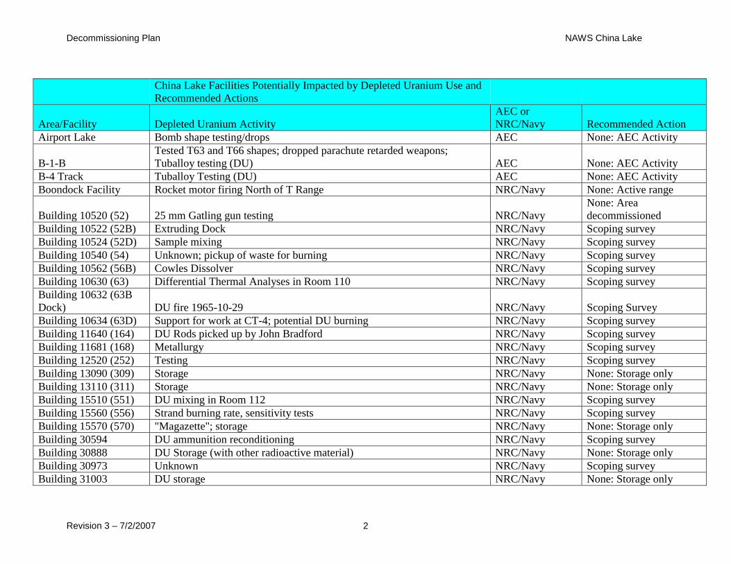
Decommissioning Plan NAWS China Lake
Revision 3 – 7/2/2007 2
China Lake Facilities Potentially Impacted by Depleted Uranium Use and
Recommended Actions
Area/Facility Depleted Uranium Activity
AEC or
NRC/Navy Recommended Action
Airport Lake Bomb shape testing/drops AEC None: AEC Activity
B-1-B
Tested T63 and T66 shapes; dropped parachute retarded weapons;
Tuballoy testing (DU) AEC None: AEC Activity
B-4 Track Tuballoy Testing (DU) AEC None: AEC Activity
Boondock Facility Rocket motor firing North of T Range NRC/Navy None: Active range
Building 10520 (52) 25 mm Gatling gun testing NRC/Navy
None: Area
decommissioned
Building 10522 (52B) Extruding Dock NRC/Navy Scoping survey
Building 10524 (52D) Sample mixing NRC/Navy Scoping survey
Building 10540 (54) Unknown; pickup of waste for burning NRC/Navy Scoping survey
Building 10562 (56B) Cowles Dissolver NRC/Navy Scoping survey
Building 10630 (63) Differential Thermal Analyses in Room 110 NRC/Navy Scoping survey
Building 10632 (63B
Dock) DU fire 1965-10-29 NRC/Navy Scoping Survey
Building 10634 (63D) Support for work at CT-4; potential DU burning NRC/Navy Scoping survey
Building 11640 (164) DU Rods picked up by John Bradford NRC/Navy Scoping survey
Building 11681 (168) Metallurgy NRC/Navy Scoping survey
Building 12520 (252) Testing NRC/Navy Scoping survey
Building 13090 (309) Storage NRC/Navy None: Storage only
Building 13110 (311) Storage NRC/Navy None: Storage only
Building 15510 (551) DU mixing in Room 112 NRC/Navy Scoping survey
Building 15560 (556) Strand burning rate, sensitivity tests NRC/Navy Scoping survey
Building 15570 (570) "Magazette"; storage NRC/Navy None: Storage only
Building 30594 DU ammunition reconditioning NRC/Navy Scoping survey
Building 30888 DU Storage (with other radioactive material) NRC/Navy None: Storage only
Building 30973 Unknown NRC/Navy Scoping survey
Building 31003 DU storage NRC/Navy None: Storage only

Decommissioning Plan NAWS China Lake
Revision 3 – 7/2/2007 3
Building 31018 DU storage NRC/Navy None: Storage only
Building 31110 Storage of shot up tow targets from DU munitions tests NRC/Navy Scoping survey
Burro Canyon DU overshots NRC/Navy None
Cole Flats AEC weapon firing (Big Stoop, Project R, Big Beast) AEC None: AEC Activity
Coso Military Target
Range
Material from A-7 Crash Site: probably aircraft counterweights; DU
contaminated target vehicles NRC/Navy None: Active range
CT-1 Projectile firing; "A bomb work"; possible burial
AEC and
NRC/Navy Scoping survey
CT-3 Camel Test, Post WWII AEC None: AEC Activity
CT-4 Waste disposal NRC/Navy Scoping survey
CT-6 Fuel Burn Test Area NRC/Navy Scoping survey
Dead Man Canyon DU overshots NRC/Navy None
G-1 Range Air burst of war reserve weapons ca 1958 (Operational Suitability Tests) AEC None: AEC Activity
G-2 Range Air burst of war reserve weapons ca 1959 (Operational Suitability Tests) AEC None: AEC Activity
G-6 Range Phalanx testing NRC/Navy None: Active range
K-2 Gunnery Range DU and HE ammunition testing NRC/Navy Decommissioning
Kennedy Stands 25 mm gun tests from Harrier and helicopter NRC/Navy Decommissioning
LC Range Shape testing AEC None: AEC Activity
Magazette 45M-4-13 25 mm ammunition storage NRC/Navy None: Building gone
OST-1 (Off-Station
Target) Bomb drop prior to 1957 AEC None: AEC Activity
Salt Wells Pilot Plant Powder mixing in Bldg's in this Area 12520, 15560, 15510 and 15700 NRC/Navy Scoping survey
Site 6 Burn Area NRC/Navy None: Area studied
Skytop, Skytop Playa,
Mineshafts Waste disposal NRC/Navy
None: Surveyed and
backfilled
SNORT Gun and bomb shape tests
AEC and
NRC/Navy None: Active range
Tower 11 120 mm gun tests NRC/Navy Decommissioning
T-Range Burning
Ground Waste disposal/burning: trenches moved around NRC/Navy
Combine with Site 6.
Area surveyed.
X-3 Crater Bomb drop prior to 1957 AEC None: AEC Activity
X-Pad at NAF Weapons component handling AEC None: AEC Activity
Decommissioning Plan NAWS China Lake
Revision 3 – 7/2/2007 1
Attachment 2
Additional Photographs
Of K-2 Gunnery Range And
Kennedy Stands
Decommissioning Plan NAWS China Lake
Revision 3 – 7/2/2007 2
Attachment 3
RESRAD Computer Model Results

Decommissioning Plan NAWS China Lake
Revision 3 – 7/2/2007 1
Attachment 4
Cost Estimation
Can we have bigger print in this Appendix. I know this was made from a spreadsheet and
transferred to adobe but please find a way to make the print more readable (larger), especially the
last page.
Need to update the target disposal cost to $1,442,161 per the year end exercise last year.
Need to update other soil disposal transportation costs because the nearest railhead to the target
areas is appx 15 miles away vice on site nearby and make current due to fuel increase as best you
can.
After recalculating the cost estimate, remember to update the cost in the ALARA section in the
DP and the alternatives discussion.