Decommissioning of Underground Structures, Systems and ... · Underground Structures, Systems and...
217
Decommissioning of Underground Structures, Systems and Components Technical Reports SeriEs No. 439
Transcript of Decommissioning of Underground Structures, Systems and ... · Underground Structures, Systems and...
Decommissioning of Underground Structures,
Systems and Components
Technical Reports SeriEs No. 439

DECOMMISSIONING OF UNDERGROUND STRUCTURES,
SYSTEMS AND COMPONENTS

The following States are Members of the International Atomic Energy Agency:
AFGHANISTANALBANIAALGERIAANGOLAARGENTINAARMENIAAUSTRALIAAUSTRIAAZERBAIJANBANGLADESHBELARUSBELGIUMBENINBOLIVIABOSNIA AND HERZEGOVINABOTSWANABRAZILBULGARIABURKINA FASOCAMEROONCANADACENTRAL AFRICAN REPUBLICCHADCHILECHINACOLOMBIACOSTA RICACÔTE D’IVOIRECROATIACUBACYPRUSCZECH REPUBLICDEMOCRATIC REPUBLIC OF THE CONGODENMARKDOMINICAN REPUBLICECUADOREGYPTEL SALVADORERITREAESTONIAETHIOPIAFINLANDFRANCEGABONGEORGIAGERMANYGHANA
GREECEGUATEMALAHAITIHOLY SEEHONDURASHUNGARYICELANDINDIAINDONESIAIRAN, ISLAMIC REPUBLIC OF IRAQIRELANDISRAELITALYJAMAICAJAPANJORDANKAZAKHSTANKENYAKOREA, REPUBLIC OFKUWAITKYRGYZSTANLATVIALEBANONLIBERIALIBYAN ARAB JAMAHIRIYALIECHTENSTEINLITHUANIALUXEMBOURGMADAGASCARMALAYSIAMALIMALTAMARSHALL ISLANDSMAURITANIAMAURITIUSMEXICOMONACOMONGOLIAMOROCCOMYANMARNAMIBIANETHERLANDSNEW ZEALANDNICARAGUANIGERNIGERIANORWAYPAKISTAN
PANAMAPARAGUAYPERUPHILIPPINESPOLANDPORTUGALQATARREPUBLIC OF MOLDOVAROMANIARUSSIAN FEDERATIONSAUDI ARABIASENEGALSERBIA AND MONTENEGROSEYCHELLESSIERRA LEONESINGAPORESLOVAKIASLOVENIASOUTH AFRICASPAINSRI LANKASUDANSWEDENSWITZERLANDSYRIAN ARAB REPUBLICTAJIKISTANTHAILANDTHE FORMER YUGOSLAV REPUBLIC OF MACEDONIATUNISIATURKEYUGANDAUKRAINEUNITED ARAB EMIRATESUNITED KINGDOM OF GREAT BRITAIN AND NORTHERN IRELANDUNITED REPUBLIC OF TANZANIAUNITED STATES OF AMERICAURUGUAYUZBEKISTANVENEZUELAVIETNAMYEMENZAMBIAZIMBABWE
The Agency’s Statute was approved on 23 October 1956 by the Conference on the Statute othe IAEA held at United Nations Headquarters, New York; it entered into force on 29 July 1957The Headquarters of the Agency are situated in Vienna. Its principal objective is “to accelerate andenlarge the contribution of atomic energy to peace, health and prosperity throughout the world’’.
f .

TECHNICAL REPORTS SERIES No. 439
DECOMMISSIONING OF UNDERGROUND STRUCTURES,
SYSTEMS AND COMPONENTS
INTERNATIONAL ATOMIC ENERGY AGENCYVIENNA, 2006

IAEA Library Cataloguing in Publication Data
Decommissioning of underground structures, systems and components. — Vienna : International Atomic Energy Agency, 2006.
p. ; 24 cm. — (Technical reports series, ISSN 0074–1914 ; no. 439)STI/DOC/010/439ISBN 92–0–104405–4Includes bibliographical references.
1. Underground nuclear power plants. — Decommissioning. 2. Underground storage tanks — Decommissioning. I. International Atomic Energy Agency. II. Technical reports series (International Atomic Energy Agency) ; 439.
IAEAL 06–00431
COPYRIGHT NOTICE
All IAEA scientific and technical publications are protected by the terms of the Universal Copyright Convention as adopted in 1952 (Berne) and as revised in 1972 (Paris). The copyright has since been extended by the World Intellectual Property Organization (Geneva) to include electronic and virtual intellectual property. Permission to use whole or parts of texts contained in IAEA publications in printed or electronic form must be obtained and is usually subject to royalty agreements. Proposals for non-commercial reproductions and translations are welcomed and will be considered on a case by case basis. Enquiries should be addressed by email to the Publishing Section, IAEA, at [email protected] or by post to:
Sales and Promotion Unit, Publishing SectionInternational Atomic Energy AgencyWagramer Strasse 5P.O. Box 100A-1400 ViennaAustriafax: +43 1 2600 29302tel.: +43 1 2600 22417http://www.iaea.org/books
© IAEA, 2006
Printed by the IAEA in AustriaApril 2006
STI/DOC/010/439

FOREWORD
A large number of operational and shut down nuclear installations have underground systems, structures and components such as pipes, tanks or vaults. This practice of incorporating such features into the design of nuclear facilities has been in use for an extended period of time during which decommissioning was not perceived as a serious issue and was rarely considered in plant design and construction. Underground features can present formidable decontamination and/or dismantling issues, and these are addressed in this report. Decommissioning issues include, among others, difficulty of access, the possible need for remotely operated technologies, leakage of the contents and the resulting contamination of foundations and soil, as well as issues such as problematic radiological characterization.
Although to date there have been more than 40 IAEA publications on decommissioning, none of them has ever addressed this subject. Although cases of decommissioning of such facilities have been described in the technical literature, no systematic treatment of relevant decommissioning strategies and technologies is currently available. It was perhaps assumed that generic decontamination and dismantling approaches would also be adequate for these ‘difficult’ facilities. This may be only partly true due to a number of unique physical, layout and radiological characteristics. With growing experience in the decommissioning field, it is timely to address this subject in a systematic and comprehensive fashion.
Practical guidance is given in this report on relevant decommissioning strategies and technologies for underground features of facilities. Also described are alternative design and construction approaches that could facilitate a smoother path forward through the decommissioning process. The objective of this report is to highlight important points in the decommissioning of underground systems, structures or components for policy makers, operators, waste managers and other parties, drawing on the collective experience of some Member States. Following the preliminary drafting, a series of consultants meetings was held to review and amend this report, which included the participation of a number of international experts. The IAEA officer responsible for this publication was M. Laraia of the Division of Nuclear Fuel Cycle and Waste Technology.

EDITORIAL NOTE
Although great care has been taken to maintain the accuracy of information contained in this publication, neither the IAEA nor its Member States assume any responsibility for consequences which may arise from its use.
The use of particular designations of countries or territories does not imply any judgement by the publisher, the IAEA, as to the legal status of such countries or territories, of their authorities and institutions or of the delimitation of their boundaries.
The mention of names of specific companies or products (whether or not indicated as registered) does not imply any intention to infringe proprietary rights, nor should it be construed as an endorsement or recommendation on the part of the IAEA.

CONTENTS
1. INTRODUCTION . . . . . . . . . . . . . . . . . . . . . . . . . . . . . . . . . . . . . . . . . 1
1.1. Purpose and scope . . . . . . . . . . . . . . . . . . . . . . . . . . . . . . . . . . . . . 21.2. Structure . . . . . . . . . . . . . . . . . . . . . . . . . . . . . . . . . . . . . . . . . . . . . 4
2. PAST PRACTICE VERSUS CURRENT STANDARDS . . . . . . . . 4
2.1. Relevant factors in past practice . . . . . . . . . . . . . . . . . . . . . . . . . 42.2. Relevant practices in current design and construction . . . . . . 6
3. STRATEGIES AND PLANNING . . . . . . . . . . . . . . . . . . . . . . . . . . . 8
3.1. Strategy development . . . . . . . . . . . . . . . . . . . . . . . . . . . . . . . . . 83.1.1. Future use of a site . . . . . . . . . . . . . . . . . . . . . . . . . . . . . . . 103.1.2. Site cleanup criteria/end state specification . . . . . . . . . . 113.1.3. Entombment decisions . . . . . . . . . . . . . . . . . . . . . . . . . . . 11
3.2. Detailed planning and engineering . . . . . . . . . . . . . . . . . . . . . . . 123.2.1. Inputs to project planning . . . . . . . . . . . . . . . . . . . . . . . . . 123.2.2. Key engineering issues. . . . . . . . . . . . . . . . . . . . . . . . . . . . 163.2.3. Implementation aspects. . . . . . . . . . . . . . . . . . . . . . . . . . . 183.2.4. Feedback . . . . . . . . . . . . . . . . . . . . . . . . . . . . . . . . . . . . . . . 213.2.5. Project baseline . . . . . . . . . . . . . . . . . . . . . . . . . . . . . . . . . 21
3.3. Selection of optimum decommissioning strategy . . . . . . . . . . . 223.4. Uncertainties in the transition from planning to execution . . . 23
4. DECOMMISSIONING EXPERIENCE AND TECHNOLOGIES FOR UNDERGROUND PIPING . . . . . . . . . . 24
4.1. Characterization of physical, radiological and hazardous materials . . . . . . . . . . . . . . . . . . . . . 254.1.1. Geophysical characterization objectives . . . . . . . . . . . . . 274.1.2. Geophysical characterization techniques . . . . . . . . . . . . 284.1.3. Non-destructive testing . . . . . . . . . . . . . . . . . . . . . . . . . . . 284.1.4. Radiological characterization . . . . . . . . . . . . . . . . . . . . . . 324.1.5. Characterizaion of hazardous constituents . . . . . . . . . . . 36
4.2. Cutting and removal . . . . . . . . . . . . . . . . . . . . . . . . . . . . . . . . . . . 384.2.1. Preparations for work . . . . . . . . . . . . . . . . . . . . . . . . . . . . 384.2.2. Thermal cutting . . . . . . . . . . . . . . . . . . . . . . . . . . . . . . . . . 40
4.2.3. Mechanical cutting . . . . . . . . . . . . . . . . . . . . . . . . . . . . . . . 414.2.4. Technique evaluation and selection . . . . . . . . . . . . . . . . . 44
4.3. Selected experience in dismantling of piping . . . . . . . . . . . . . . . 444.4. Worker protection . . . . . . . . . . . . . . . . . . . . . . . . . . . . . . . . . . . . . 52
5. DECOMMISSIONING EXPERIENCE AND TECHNOLOGIES FOR UNDERGROUND TANKS . . . . . . . . . . 53
5.1. Physical and radiological characterization . . . . . . . . . . . . . . . . . 545.1.1. Physical characterization. . . . . . . . . . . . . . . . . . . . . . . . . . 545.1.2. Radiological characterization . . . . . . . . . . . . . . . . . . . . . . 56
5.2. Dismantling techniques for underground tanks . . . . . . . . . . . . 595.2.1. Methods for cutting of metallic components . . . . . . . . . 595.2.2. Concrete structures . . . . . . . . . . . . . . . . . . . . . . . . . . . . . . 61
5.3. Selected experience with tank waste removal projects . . . . . . . 625.3.1. Waste removal in the USA . . . . . . . . . . . . . . . . . . . . . . . . 625.3.2. Waste removal from the A-1 nuclear power plant
in Slovakia. . . . . . . . . . . . . . . . . . . . . . . . . . . . . . . . . . . . . . 645.3.3. Waste removal from Magnox power stations
in the UK. . . . . . . . . . . . . . . . . . . . . . . . . . . . . . . . . . . . . . . 655.3.4. Waste removal from Garigliano nuclear power plant
in Italy . . . . . . . . . . . . . . . . . . . . . . . . . . . . . . . . . . . . . . . . . 685.4. Entombment of underground tanks . . . . . . . . . . . . . . . . . . . . . . 69
6. SELECTED DECOMMISSIONING EXPERIENCE FOR VAULTS AND TUNNELS . . . . . . . . . . . . . . . . . . . . . . . . . . . . . 71
6.1. Waste removal, decontamination and dismantling projects . . . 726.1.1. Energy Technology Engineering Center,
Canoga Park, California . . . . . . . . . . . . . . . . . . . . . . . . . . 726.1.2. Idaho chemical processing plant, Idaho Falls . . . . . . . . . 736.1.3. Fort St. Vrain nuclear power plant, Colorado . . . . . . . . 736.1.4. Garigliano nuclear power plant, Italy . . . . . . . . . . . . . . . 736.1.5. Phase separator pit, Los Alamos, New Mexico . . . . . . . 756.1.6. Hot cells in Building A59, Winfrith, UK. . . . . . . . . . . . . 756.1.7. Map Tube facility, Argonne, Illinois. . . . . . . . . . . . . . . . . 766.1.8. Lucens experimental power reactor, Switzerland . . . . . 766.1.9. Vandellós 1 graphite vaults, Spain . . . . . . . . . . . . . . . . . . 77
6.2. Vault entombment projects . . . . . . . . . . . . . . . . . . . . . . . . . . . . . 77
7. CONCLUSIONS AND RECOMMENDATIONS . . . . . . . . . . . . . . 80
REFERENCES . . . . . . . . . . . . . . . . . . . . . . . . . . . . . . . . . . . . . . . . . . . . . . . . . 82
ANNEXES I–IX: EXAMPLES OF NATIONAL EXPERIENCE. . . . . . 95
ANNEX I: DECOMMISSIONING OF A SECTION OF A DISCHARGE LINE IN BELGIUM . . . . . . . . . . . . . . . . . 97
ANNEX II: SITUATION OF UNDERGROUND COMPONENTS IN THE NUCLEAR RESEARCH INSTITUTE AT ŘEŽ, CZECH REPUBLIC . . . . . . . . . . . . . . . . . . . . . . 106
ANNEX III: DECOMMISSIONING AT VANDELLÓS 1 NUCLEAR POWER PLANT, SPAIN: EMBEDDED AND UNDERGROUND COMPONENTS . . . . . . . . . . . 115
ANNEX IV: DECOMMISSIONING AND SITE RESTORATION OF THE SWISS UNDERGROUND EXPERIMENTAL POWER REACTOR AT LUCENS . . . . . . . . . . . . . . . . . . 123
ANNEX V: RECENT EXPERIENCE IN DECOMMISSIONING DRAINS AND UNDERGROUND DUCTS, UK . . . . . . 137
ANNEX VI: OPERATING EXPERIENCE WITH DECOMMISSIONING OF UNDERGROUND COMPONENTS, USA . . . . . . . . . . . . . . . . . . . . . . . . . . . . . 144
ANNEX VII: RECENT EXPERIENCE IN DECOMMISSIONING OF UNDERGROUND TANKS AT THE JASLOVSKÉ BOHUNICE A-1 NUCLEAR POWER PLANT, SLOVAKIA . . . . . . . . . . . . . . . . . . . . . . . . . . . . . . . . . . . . . . 151
ANNEX VIII: EXPERIENCE WITH UNDERGROUND PIPELINES AND DUCTS AT THE CIRUS REACTOR, INDIA . . . 162
ANNEX IX: STRATEGY FOR DECOMMISSIONING OF UNDERGROUND PIPES AT THE NATIONAL INSTITUTE OF ONCOLOGY AND RADIOBIOLOGY IN HAVANA, CUBA . . . . . . . . . . . . 171

ANNEX X: LESSONS LEARNED DURING DECOMMISSIONING OF UNDERGROUND STRUCTURES, SYSTEMS AND COMPONENTS . . . . 182
CONTRIBUTORS TO DRAFTING AND REVIEW . . . . . . . . . . . . . . . . 204
1. INTRODUCTION
The number of successfully planned and completed decommissioning projects is steadily increasing, along with the confidence of most stakeholders in the feasibility of the operator being able to safely perform decommissioning of nuclear facilities. This is important as considerations and assessments about facility life extension and life cycle management can be measured against realistic end points.
After over a decade of implementing major decommissioning projects, the technology to support decommissioning has advanced considerably and has benefited from parallel developments in other industrial fields such as electronics, robotics and computing. New and enhanced decommissioning technologies have emerged and are available to address the new challenges of the twenty-first century, when a number of larger commercial facilities will reach the end of their operational lives and become candidates for decommissioning [1]. These decommissioning efforts allow the decommissioning community the opportunity to test and further optimize decontamination and disassembly techniques, as well as to evaluate other technological solutions to traditional problem areas in the field. The end result of this process is the creation of a ‘decommissioning market’, including specialized suppliers and contractors. The worldwide impetus to plan for and implement large decommissioning projects has resulted inter alia in a number of decommissioning handbooks issued by either national [2, 3] or international [1, 4, 5] organizations.
The current situation in the decommissioning technologies area can be briefly described as follows. Although the decommissioning market cannot yet be regarded as fully mature in all developed countries, the key elements of strategy development, characterization, waste management, decontamination, dismantling and licence termination have been separately demonstrated as being fully achievable [6]. However, in its international role, the IAEA is faced with a wide variety of differing national situations relative to the availability of technical, human and financial resources in some of these situations. While it is recognized that nuclear decommissioning already is or may soon become a routine activity in some developed countries, the situation is by no means so clear in other countries. In addition, transfer of technologies and expertise from developed to developing countries is not a spontaneous or easy process, and will take time and considerable effort [7].
Since 1975 well over 40 technical reports, conference proceedings, reports and Safety Series reports have been published by the IAEA, covering various aspects of decommissioning. Among these are those on the topics of: design
1
and construction features to facilitate decommissioning, national policies and regulations, specific technical aspects, safety and environmental protection, and characterization of shut down facilities. A selection of technology oriented publications is given by Refs [1, 8–11]. While most extant IAEA publications address a variety of possible applications or refer to specific types of nuclear installation, for example research reactors [12] or non-reactor facilities [13], only recently has attention been focused on the decommissioning of individual components or structures [14]. The focus of this continuing work is on those components or structures that are common among IAEA Member States and which present special hazards to the implementation of decontamination and dismantling as a part of the entire decommissioning process.
Among those facilities needing attention are underground structures, systems and components (SSCs) of the different facilities. These require special consideration, can give rise to problems in the decommissioning process and are the subject of this report. Firstly, due to their poor accessibility, there are significant difficulties in physical and radiological characterization, deployment of decontamination techniques, and implementation of physical disassembly and removal activities. Secondly, these types of component are situated in a large number of nuclear installations. However, early nuclear design and construction practices often did not consider or incorporate eventual decommissioning requirements in their design considerations. This is also true for those facilities situated in countries that do not have sufficient experience and/or expertise in performing decommissioning. Thirdly, there are no systematic bibliographies on decommissioning of underground or embedded components for nuclear facilities, despite some of the technical difficulties that have been encountered in actual projects to date. In fact, the bibliography on this subject is comprised of rather sketchy and sporadic case histories. This report is intended to draw attention to a neglected field and to collate and condense sporadic information into an overview of important factors and practical guidance.
1.1. PURPOSE AND SCOPE
The objective of this report is to identify and describe technologies and strategies for the decommissioning of underground SSCs situated at nuclear facilities, including characterization, decontamination, dismantling and management of the resulting waste streams. The unrestricted or restricted end state of such facilities is also a point of interest. The information given in this report is intended to provide consolidated experience and guidance to those planning, managing and performing the future decommissioning of such SSCs.
2

The report may also be of use to those involved in the nuclear regulatory field, when reviewing plans, carrying out inspection activities and confirming satisfactory completion of decommissioning. It will also be helpful to those undertaking refurbishment or large scale maintenance activities on operational nuclear installations. It may also be useful to those researchers looking for opportunities to improve or enhance the technologies used for future decommissioning activities.
This report addresses important factors in planning and implementing the decommissioning of a large variety of underground SSCs. It is not intended to be a decommissioning handbook. Technical details are given only to a limited extent, while the reader is directed to more detailed information sources in the quoted literature. The reader is advised not to extrapolate the future performance of a given strategy/technology without due consideration of the specific features of the facility for which planning and engineering arrangements are being developed (e.g. location, contamination levels and structural materials). Although the focus of the report is on underground SSCs, some attention is given to, as well as examples quoted for, the decommissioning of embedded SSCs, which have some factors in common with underground facilities.
Specific examples of SSCs addressed by this report include:
— Underground system piping, such as that for waste transfer and process connections;
— Underground tanks;— Underground/buried exhaust ducts;— In-ground storage tubes for samples;— Trenches used for piping runs;— Underground vaults (containing, for example, wastes, filters and tanks).
The scope of this report does not include retrieval of buried wastes from waste disposal sites; other programmes of the IAEA address this topic. Entombment is a possibility for some components addressed by this report because of their location. However, entombment is just one possible strategy; in most cases complete removal would be the preferred strategy in view of the transformation of the site into a permanently safe state with no restriction on future uses. In this report, entombment aspects are only briefly addressed to the extent that they might be applicable to the entombment of underground tanks and vaults.
3

1.2. STRUCTURE
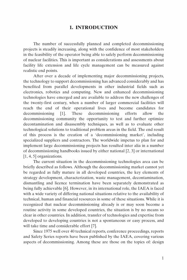
Following the introductory section, the report addresses issues typically encountered in the decommissioning of SSCs. Section 2 expands on the past practice of the use of underground components in the design of nuclear facilities and on current practices that are intended to prevent recurrence of problems experienced in the past. Section 3 describes factors important in developing strategies and plans for decommissioning of such facilities. Sections 4, 5 and 6 address the experience and technologies used in decommissioning, for underground piping, tanks, and vaults and tunnels, respectively, with the focus being on important factors affecting selection of technologies. Section 7 comprises conclusions and recommendations. The report is complemented by a list of references and ten annexes — one describing selected decommissioning projects and another describing lessons learned. The availability of web sites was assured at the time this report was prepared. Figure 1 graphically depicts the structure of the report.
The reader should note that many of the issues discussed within this report are common to all underground components (i.e. pipes, tanks and vaults), although for practical purposes information is frequently given for only one of these categories. The reader is encouraged to read all of Sections 4, 5 and 6 to appreciate the full scope of problems.
2. PAST PRACTICE VERSUS CURRENT STANDARDS
2.1. RELEVANT FACTORS IN PAST PRACTICE
The arrangement of components in many first generation nuclear facilities was not always conducive to facilitating decommissioning. In the early days of nuclear design, the emphasis was typically placed on fast construction and on a configuration for efficiency in operation, with little attention being paid to the eventual decommissioning activity. This in general led designers to give priority to simple technical solutions regardless of the fact that these could, and actually did, in some cases cause environmental contamination and additional complications during the decommissioning process. Standards for radiation protection and design criteria for decommissioning either did not exist or were left to the discretion of designers as to compliance with any regulations or standards. In other cases, the designers were not experienced in
4
designing nuclear facilities. For example, the general designers of older nuclear research institutes were usually selected because of extensive experience with the design of industrial chemical facilities, not nuclear ones. As such, the principles adopted, although deemed valid for the design of chemical facilities, did not take into account many issues that are unique to the design of nuclear facilities. At that time, legislative requirements and regulatory oversight on the specific subject of decommissioning were minimal at best.
Many of these early facilities then also contained substances that are now, but were not then, regulated (e.g. asbestos). In addition to the change in standards (constructional, environmental, etc.), new missions have been undertaken at many of these facilities over the past two decades. This has resulted in physical changes to the facilities that might eventually complicate decommissioning by enveloping or layering new parts of a facility over the old
Technology & Experience
3. Planning
5. Underground tanks
7. Conclusions
References
1. Introduction, purpose, structure
2. Past practice,current standards
4. Underground andembedded pipes
6. Undergroundvaults and tunnels
Annexes• Member States (I–IX)• Lessons learned (X)
FIG. 1. Structure of this report.
5

[15]. To indicate an estimate of the scale of problems resulting from past practices, across a wide range of industry as many as 15–20% of the approximately 1.8 million underground storage tanks and piping systems in the United States of America (USA) are now leaking or can be expected to develop leaks in the near future [16]. As one impressive example, the conditions of United States Department of Energy (USDOE) waste tanks are described in Ref. [17].
To cite a few examples, pipes were installed in concrete lined trenches to connect separate buildings or to discharge liquids to the environment. In some cases, pipes were placed inside buried trenches with no further containment. Burial was also often seen as a convenient means of reducing radiation doses from pipes. However, with time, many such pipes developed leaks, thereby contaminating trenches and the surrounding soil. This in turn can cause a significant increase in the volume of radioactive wastes from decontamination and dismantling activities — and an increase in costs that might have otherwise been avoided. Similarly, underground tanks or vaults were often installed at nuclear facilities to collect unconditioned wastes. Their underground location was frequently the result of a design choice intended to simplify transfer of radioactive wastes (either solid or liquid) by making use of gravity. It should be noted that this situation is further complicated by the lack of a treatment or conditioning infrastructure for radioactive wastes. It was assumed that waste treatment and conditioning would be deferred to the decommissioning stage (as one example, this was the case at most WWER-440 reactors [18], first generation gas cooled reactors [19–21] or other reactors [22]). Environmental regulations were significantly more lenient and not as restrictive then compared with the situation if the same work were to be done today.
2.2. RELEVANT PRACTICES IN CURRENT DESIGN AND CONSTRUCTION
Decommissioning experience has resulted in the evolution of nuclear facility design criteria for future projects that are expected to avoid many of the problems described above. Safety guidance is provided by the IAEA [23] and other sources for current and future design approaches that are more conducive to facilitating efficient decommissioning. In retrospect, understanding where such criteria have not been applied in the past can be useful in identifying potential issues and the conduct of planning for decommissioning of underground SSCs at newer facilities.
In some cases, problems encountered with deep inaccessible vaults or chambers arise either from their initial construction or as a result of their
6

configuration. During plant operation they are often used to accumulate radioactive wastes, which becomes problematic only to the decommissioning organization in the long term. The use of vaults and chambers should be avoided or at least minimized to ensure that there is a proper means of retrieving materials such as accumulated wastes stored there [10].
It is advisable that piping be routed above ground as far as possible and practical. If necessary, it is important that piping routed below ground be ‘doubly contained’ (e.g. in waterproof trenches with sumps and inspection facilities) to prevent subsoil contamination in the event of pipe leakage. Proper sloping of trench flooring would ensure passive drainage of any leakage to sumps. Failure of unlined sumps and trenches could also lead to seepage of radioactivity to the subsoil [10].
Other practical examples are given in Ref. [24], which provides comprehensive guidance for pipes, drains and tanks. This includes (elaborating from Ref. [24]):
(a) Design and placement of pipes and ducts to allow easy access, cleaning and removal.
(b) Pipes that potentially could be contaminated are not run in floors, walls and ceilings, or below concrete slabs at ground level. There should be a plan to allow access to and removal of such systems. Such pipes are run in chases or trenches and are accessible through removable hatches or panels.
(c) Design and placement of sumps and drains is intended to prevent the spread of radioactive contaminants and to facilitate cleanup. Sumps which potentially could be contaminated are double walled to provide secondary containment. Sump walls are not bolted. Seams are minimized and welds are ground flush.
(d) Tank locations and connections with operating systems are selected to minimize spread of contaminants.
(e) Tanks containing contaminated fluids are not buried but are placed in above ground rooms. If this cannot be accomplished, the following alternatives are acceptable: (i) Tanks can be placed in a buried concrete vault with a sump that
allows remote pump-out. In addition, the vault is coated, sealed or lined to prevent leakage both in and out. Access is provided to allow decontamination of the interior surface of the wall and the means to disassemble the tank.
(ii) Tanks can be buried if a double walled design is used. The area between liners is monitored to provide an early indication of leakage. The design and method of installation of buried tanks is intended to
7

facilitate their removal (e.g. buried tanks are not tied into other structural members).
A comprehensive review of what could have been done during the construction of several research reactors to assist in their decommissioning is presented in Ref. [25]. As an example, a lack of coatings or double walls strongly suggests that decommissioning planning should address the possibility of contamination spreading to the surrounding areas, structures or environment. This in turn may provide some direction for the radiological characterization needed to appropriately plan decommissioning.
The above examples of design and construction criteria for decommissioning apply especially to underground components. If care is taken, decommissioning of facilities will be substantially more straightforward than that of many of the facilities facing decommissioning today.
3. STRATEGIES AND PLANNING
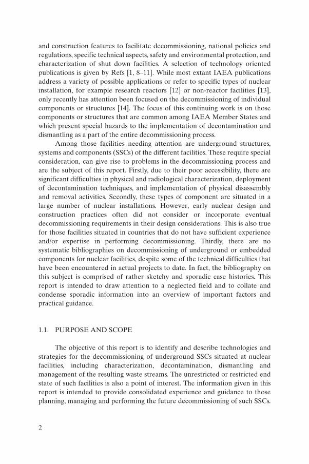
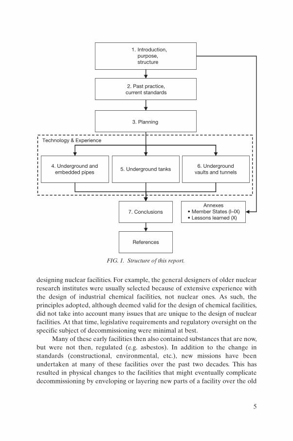
In general, planning for the decommissioning of underground facilities is similar to other decommissioning projects except that there are some aspects specific to it. These often take the form of somewhat unique problems and sometimes require specific techniques — resulting mainly from the difficulty of access and radiological issues in the work area. As with any project, planning first begins at a strategic level, which provides the overall direction for the project. The process for developing the strategy for decommissioning projects involving underground features is illustrated in Fig. 2.
The reader is advised that this figure, as well as the discussion in this section, is intended to show examples of considerations specific to underground decommissioning. It is not intended to address the complete subject of decommissioning.
3.1. STRATEGY DEVELOPMENT
As shown in Fig. 2, the strategy for decommissioning requires several inputs. Some of these inputs can directly affect the future uses of the site and
8
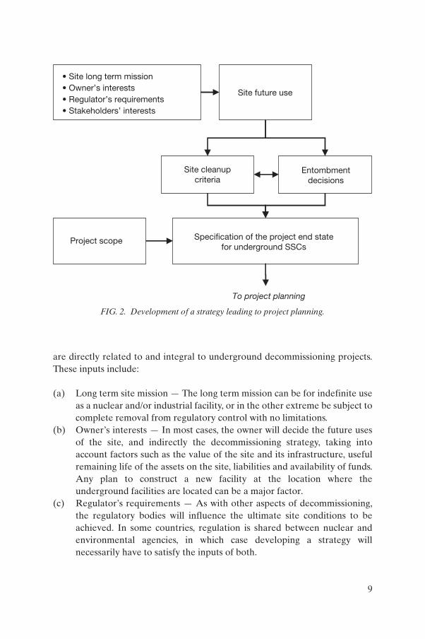
are directly related to and integral to underground decommissioning projects. These inputs include:
(a) Long term site mission — The long term mission can be for indefinite use as a nuclear and/or industrial facility, or in the other extreme be subject to complete removal from regulatory control with no limitations.
(b) Owner’s interests — In most cases, the owner will decide the future uses of the site, and indirectly the decommissioning strategy, taking into account factors such as the value of the site and its infrastructure, useful remaining life of the assets on the site, liabilities and availability of funds. Any plan to construct a new facility at the location where the underground facilities are located can be a major factor.
(c) Regulator’s requirements — As with other aspects of decommissioning, the regulatory bodies will influence the ultimate site conditions to be achieved. In some countries, regulation is shared between nuclear and environmental agencies, in which case developing a strategy will necessarily have to satisfy the inputs of both.
Site future use
Project scope
To project planning
• Site long term mission• Owner’s interests• Regulator’s requirements• Stakeholders’ interests
Specification of the project end statefor underground SSCs
Entombmentdecisions
Site cleanupcriteria
FIG. 2. Development of a strategy leading to project planning.
9
(d) Stakeholders’ interests — Various other stakeholder groups may have the ability to influence strategic decisions on criteria for completion of cleanup, influencing what is allowable to leave on-site when the project is completed. These groups can also dictate the eventual timing of decommissioning based upon the funding available and the time required to achieve various cleanup levels at the facility and/or site.
As a final conclusion of the decommissioning strategy, the future uses of the site are defined, as either:
— Immediate dismantling (total or partial);— Deferred dismantling.
The strategy selected for removal of the underground components is directly linked to the general strategy for decommissioning and in particular to the site release criteria. The selection of an immediate or deferred decommissioning strategy depends on the opportunity for future use of a site. In the case of an immediate dismantling strategy, there are usually future uses envisaged which relate to release of the site. In the case of a deferred dismantling strategy, the site remains under some licensed control awaiting decommissioning in the longer term.
The strategy for the removal of underground components is directly related to the site release criteria. Usually for release of the site it is absolutely necessary to remove the radiological components (or to demonstrate that what remains achieves regulatory compliance with the release criteria).
For the deferred decommissioning scenarios, a long term strategy for safety and environmental protection will need to be planned for and implemented, and at the end of the safe enclosure period some assessment or feedback is needed to prompt the final site release process to be re-evaluated.
3.1.1. Future use of a site
The selected strategy for underground feature decommissioning relates directly to the long term plans for the site and the cleanup criteria to be achieved.
Ideally, the long term plans for the site will be known well before decommissioning planning begins. If not, a conservative approach may be needed, which is that a relatively pristine or cleaner condition will be the end state driver for decommissioning of the underground feature. Reference [26] provides a comprehensive overview of the approaches for the reuse of decommissioned sites.
10

3.1.2. Site cleanup criteria/end state specification
Site cleanup criteria/end state specification refers to the question of whether any underground structures or components can be left in place, with or without decontamination, and what the acceptable levels are for residual radioactive and hazardous material. Excavation activities may pose technical and financial strains on the project budget. The above strategic inputs lead to a key strategic planning objective, which is to specify the end state for the underground SSCs and, for radioactive and hazardous material which can remain, whether or not a decision for entombment has been made.
Cleanup criteria are normally formulated for projects in consultation with other stakeholders. They refer to requirements for:
(a) Residual contamination (both radiological and chemical);(b) The levels of residual contamination that can be left behind at the site
after the project has been completed.
These may have an impact on the decommissioning of site facilities and without such definition the technical planning basis may be flawed or incomplete. The overall plan will need to address the protocol for measuring the residual contamination after underground structures and components have been removed, to show that the pre-established criteria have been satisfied.
The RESRAD [27] pathways analysis computer codes provide one means of developing closure criteria for completion of cleanup specific to a site. These codes have been used at several hundred locations for just such a purpose, for example at Hanford C Reactor, USA [28, 29]. An interim IAEA publication for cleanup and release of contaminated sites is available [30]. Guidance is in the course of preparation at the IAEA.
3.1.3. Entombment decisions
The very location of underground components makes them, at least in principle, candidates for using entombment as the decommissioning strategy. Other factors specific to underground components, such as difficult access for decontamination and dismantling, or long term future site uses/control issues may be conducive to implementing an entombment strategy.
Entombment of a facility, or parts thereof, is equivalent to the installation of a near surface disposal site. Therefore safety criteria for disposal sites would apply [31–33]. On-site disposal options (including entombment as a variant) are described in detail in Ref. [34], together with advantages and disadvantages, and major factors are highlighted. In situ disposal (entombment) that includes
11
encapsulation (of a reactor) and subsequent restriction of access is recognized as a viable option by the IAEA under certain circumstances [23]. Experience and studies on entombment as a decommissioning strategy are reported in Ref. [34]. Specific examples of entombment of tanks and vaults are included in Sections 7 and 8. While tanks and vaults are suitable for entombment, removal of piping is typically easier than entombment and the latter is usually not considered for piping, unless the piping is deeply buried (experience in the United Kingdom (UK) is described in Annex V) due to industrial safety concerns.
3.2. DETAILED PLANNING AND ENGINEERING
Once decommissioning strategy decisions have been made and the end state is specified, plans that implement the strategy and fully develop the details of the activities, a project schedule and a project cost estimate (from which a budget is derived) can be formulated by the staff. The overall sequence of activities for planning implementation, with some of the specifics for underground decommissioning projects, is illustrated in Fig. 3. One important aspect is monitoring, including both compliance with both material clearance criteria and site remediation criteria. Clearly the development of a decommissioning plan is much broader than the topics shown in this figure. The purpose here is to emphasize subjects that are key to underground decommissioning. Each of these is addressed in the following sections.
3.2.1. Inputs to project planning
The first step in developing a decommissioning plan is deciding what level and type of characterization is to be conducted to support the development of the project.
3.2.1.1. Project requirements
A wide variety of project requirements will assist in determining the characterization needs for a project. Four examples of characterization drivers specific to gaining the requisite understanding of the situation are:
(1) Location — Knowledge of the location, within reasonable accuracy, of the underground SSCs that are within the scope of the project. Equally
12
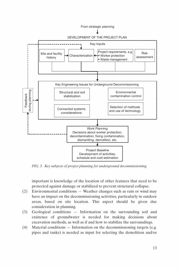
important is knowledge of the location of other features that need to be protected against damage or stabilized to prevent structural collapse.
(2) Environmental conditions — Weather changes such as rain or wind may have an impact on the decommissioning activities, particularly in outdoor areas, based on site location. This aspect should be given due consideration in planning.
(3) Geological conditions — Information on the surrounding soil and existence of groundwater is needed for making decisions about excavation methods, as well as if and how to stabilize the surroundings.
(4) Material conditions — Information on the decommissioning targets (e.g. pipes and tanks) is needed as input for selecting the demolition and/or
DEVELOPMENT OF THE PROJECT PLAN
From strategic planning
Key Inputs
Characterization
Key Engineering Issues for Underground Decommissioning
Site and facilityhistory
Project requirements, e.g.• Worker protection• Waste management
Riskassessment
Structural and soilstabilization
Environmentalcontamination control
Connected systemsconsiderations
Selection of methodsand use of technology
Feed
bac
kd
urin
g p
lann
ing
Work PlanningDecisions about worker protection,
decontamination, fixing contamination,dismantling, demolition, etc.
Project BaselineDevelopment of activities,
schedule and cost estimation
FIG. 3. Key subjects of project planning for underground decommissioning.
13

removal methods and technologies, as well as whether there is a need for special methods.
Some examples of data needs that are not necessarily related to the location and material conditions, but which are essential to planning characterization, are:
(1) Worker protection and environmental protection planning — This implies accurate knowledge about the possible existence of radioactive or hazardous contaminants (e.g. radioisotope composition and physicochemical nature), either inside or outside of the decommissioning targets.
(2) Waste management planning — Characterization information is used to estimate the types and quantities of expected waste. Where the amount of material to be excavated is large, volume estimates will be needed for backfill as well as waste management.
Comprehensive discussions of planning for decommissioning are provided in Refs [35, 36].
3.2.1.2. Site and facility history
A review of site and facility construction and operating history is the first step in gathering information that will aid in planning the characterization needs for underground decommissioning. The overall objective of the historical review is to provide detail, to the extent possible for poorly recorded or unrecorded modifications, of what has passed through systems and tanks, residual bottom contents in tanks, which may have resulted in contamination of vaults and surrounding soils, spill incidents that may have contaminated surrounding soils, location of abandoned SSCs, etc.
The primary sources for a historical review of underground decommissioning include:
(a) Review of historical records (as-built drawings, lists of construction materials, etc.). Reference [11] provides guidance for reviews of radiological records, while Ref. [35] provides experience of and guidelines for identifying and keeping decommissioning oriented records.
(b) Photographs, in particular those taken during construction or modifications to underground SSCs.
(c) Review of operating logs can be considered. However, this can be a tedious task if operations took place over several years, therefore in doing
14

so, review instructions should have specific objectives (e.g. searching for spills).
(d) Interviews with workers at the facility, and possibly with retirees, who have knowledge that may not have been recorded. Caution should be exercised, since anecdotal evidence can be incorrect or misleading.
3.2.1.3. Characterization
Relative to above ground decommissioning, factors such as access difficulties and uncertainties in underground SSC location may require special consideration when compared with decommissioning of other structures. This is relevant when choosing instruments, instrument delivery systems, sampling methods and analytical techniques. Sections 6–8 of this report provide examples of different underground characterization approaches.
A characterization survey should be implemented as an input for the planning and implementation of an underground decommissioning project and typically includes three phases:
(1) Previous characterization;(2) Ongoing characterization;(3) Final survey of the affected site.
Ideally all the needed characterization will be obtained prior to the start of excavations. In practice, this may not be possible. For example, conducting in situ characterization may be very costly, or good records regarding configuration may simply not be available. An alternative approach to characterization is to obtain the data and information as the work proceeds. In doing so, an extra measure of care may be needed to prevent inadvertent damage or to check for hazards more frequently. The result will be slower progress in conducting the work. A compensating value will be directly obtained data where otherwise indirect methods might have been used to infer and interpret actual conditions. A good deal of characterization methodologies and techniques as described in Ref. [11] would be well applicable to underground SSCs.
3.2.1.4. Risk assessment for project decisions
As for any other decommissioning project, a project risk assessment is focused on identifying factors that could have a negative impact on the project in terms of, for example, the objectives, schedule, costs, minimization of worker exposure and wastes generated. In the case of the decommissioning of
15

underground pipes, tanks and other components, project risk management is of particular concern because of major uncertainties resulting from the age of the equipment to be decommissioned, poor records from the past and, under some circumstances, difficulty of obtaining an accurate assessment prior to starting the decommissioning activities (Section 3.2.1.3). More details on project risk management can be found in Ref. [36].
In particular, radiological risk assessment is of value for decisions on the project scope. For example, Ref. [37] presents a case in which the risks to the public from a leaking pipe were weighed against the risks to the workers during repair and/or removal activities on the piping.
3.2.2. Key engineering issues
As with any decommissioning project, there is a broad range of engineering issues to be addressed. The discussion here focuses on four issues of special importance to underground decommissioning: structural and soil stability, environmental contamination control, connected systems and technology selection.
3.2.2.1. Structural and soil stability
Removal of underground components involving substantial excavation requires special attention to be paid to the possibility of disturbing the support for adjacent or connected structures. In addition, structural analysis and design of cribbing and retaining walls to prevent collapse of surrounding soil is essential. While the civil engineering discipline for addressing such issues is standard for construction projects, this is not the case for most aspects of a decommissioning project. Thus, managers of underground decommissioning projects adapt and ensure relevant conformance to these accepted standards. One possible approach often referred to is called ‘configuration management’ and is described in Ref. [38].
3.2.2.2. Environmental contamination control
An outdoors working environment is characteristic of underground decommissioning activities. For this reason, the potential for contamination of the environment demands special consideration, specifically:
(a) Dust and vapour generated while uncovering or opening contaminated SSCs are important factors. For small jobs or cases of minimal contamination, water sprays are often used during demolition. In other
16

situations, control may involve setting up of tents, and in many cases temporary ventilation and air filtering systems.
(b) Storm water will need to be considered, including collection and sampling provisions, regardless of whether rainwater can contact contaminated objects. Placement of a storm water collection basin is coordinated with setting up a tent when the latter is used for dust and vapour control.
(c) The potential for groundwater contamination exists where there are residual liquids contained in tanks, piping and vault sumps, etc., that are to be decommissioned. Care is needed to ensure capture of such contaminants. When pre-demolition characterization has identified such a potential, workers are forewarned. In other cases, where there is a reasonable potential for the presence of such liquids but the situation cannot be determined until the target has been opened, contingency measures are important elements of the planning.
3.2.2.3. Connected systems
Special attention is needed for underground systems connecting different facilities. Engineering considerations include:
(a) Choosing a location and method for isolating connected systems. This applies to utility systems that supply the facility being demolished, and to both process and utility systems that connect to other facilities. A wide range of systems needs to be considered such as electricity, data and communications, water, process waste, sewers (storm and sanitary), compressed air and natural gas.
(b) Choosing whether to install a new system or to relocate an existing system instead of attempting to retain the existing configuration (e.g. a high efficiency particulate air (HEPA) ventilation unit for an underground structure). In some cases, such decisions will be straightforward, and in other cases a detailed cost–benefit evaluation may be required.
3.2.2.4. Technology selection
A variety of tools and methods are available for dismantling and demolition. Many are standard and the choice is a matter of convenience, availability, power source or other factors. One of the main considerations for underground decommissioning is difficulties of access, which may dominate the selection, or even dictate the need to develop tools with special configurations. There is a discussion of some of these in Sections 6–8.
17
The selection of methods and technologies depends mainly on two relevant factors:
(1) Radiological: dose rates or contamination levels in the working area;(2) Physical: accessibility of the working area.
These two input parameters are essential in the initial phases of the project and will also be the key matters for lessons learned for the future.
In many cases selection of the technologies may not immediately appear to be easy. Therefore, it is useful to adopt a cost–benefit assessment approach to assist in clarifying the alternatives, taking into account both the technical and the economic issues for the available options.
Manned access for decontamination and dismantling activities is often constrained by high radiation fields, from operation and decommissioning generated radioactive contamination and dust, and in particular by limited access that is further restricted by the physical arrangement in the work area. Decommissioning tasks (such as cutting, demolishing and removing debris) require dependable and rugged equipment under varying and potentially unstable structural conditions (e.g. slippery or uneven ground).
Hence, the operating environments in underground decommissioning can quite often present special difficulties to both humans and complex remote handling equipment or robots. Proven equipment, if adapted to overcome these constraints, can offer cost effective means for performing the typical tasks of an underground decommissioning project [39]. In many cases, a trade-off may be needed between conventional approaches: the development of innovative technologies and tools versus the adaptation of proven equipment. Key factors for trade-off studies in cases of underground demolition are that configurations are unique and/or a one-off situation may exist. Because of these same factors automation is generally minimized to the greatest degree practical whenever deciding on the use of remote technology for underground decommissioning.
A comprehensive discussion of robotic and remote operation equipment is given in Ref. [1]. It includes deployment systems, viewing and detection, segmenting and disassembly, decontamination and material handling.
3.2.3. Implementation aspects
The final phase is work implementation, using the results of the inputs from the previous sections and engineering assessments. Alternatives are analysed and decisions made to confirm the main activities in the project and schedule. For example, the timing of the removal of underground components
18

needs careful consideration. The decision is usually taken on the basis of accessibility: i.e. the components can be removed prior to demolition, or if this is too difficult (or is unsafe) removal will be carried out in parallel with demolition.
3.2.3.1. Decontamination
The subject of how to deal with contamination before demolition and component removal is an important one. The decision on whether to decontaminate or to fix contamination, in situ or ex situ, to a surface involves many trade-offs. Decontamination for underground decommissioning will usually be undertaken for purposes of:
— Meeting the requirements of clearance criteria;— Preventing or minimizing airborne activity;— Achieving a less severe waste classification, for example to recycle metal,
or ideally to allow unrestricted release;— Removing or demolishing a component.
One example is that of an underground tank which contains contaminated sludge. Decisions for this work will need to address the questions of how to remove and process the material before the tank is demolished. Another example are corroded pipes that may be leaking and that are externally contaminated, which will require decisions on liquids removal and on how to prevent spread of contamination during removal. Yet another similar example are contaminated walls of a vault.
A good deal of decontamination work using fixative technologies is applicable to all aspects of a decommissioning project. They are described at length in the technical literature. This also includes general applicability to large volumes and closed systems, segmented parts, and building surfaces and structures [1–3, 5, 40, 41]. Thus, decontamination techniques are not unique to underground decommissioning and are not discussed in detail in this report.
3.2.3.2. Worker safety
For underground decommissioning, worker protection is an important input to the selection of technologies, engineering planning and work planning. Typical hazards at the facilities described in this report include heavy equipment operation, lifting and rigging, noise, falling objects, eye hazards, radiation exposure, entry work to confined spaces, fire hazards, electric shocks, soil collapse and heat stress.
19

In particular, for underground decommissioning, special emphasis needs to be paid to safety issues related to:
(a) Opening and entering closed spaces — This applies to tanks, vaults and tunnels, especially those that have been closed for a long period of time.
(b) Biological hazards — In closed spaces, particularly vaults and tunnels, there is a potential for biological hazards such as mold, dead birds and rodents, and animal faeces.
(c) Chemical hazards — Examples include tanks that contain or once contained caustic and acidic solutions.
(d) Buried and embedded electrical systems — These present the double challenge of location and doubly ensuring that circuits are de-energized. In Ref. [42] it is noted that 24% of electrical intrusion events in the review period occurred during decommissioning.
Cumbersome personal protective equipment, hot summer weather, indoor work in poorly or non-ventilated areas and physically demanding work can all hinder a worker’s ability to remain cool. As the body temperature of the worker rises, productivity and quality of work are likely to diminish, and the risk of accidents or unnecessary radiological exposures increases. This seems to be particularly relevant in decommissioning activities involving long periods in the underground confined spaces and cubicles addressed by this report (see also Ref. [43]). Section 6.4 provides more details about worker protection.
3.2.3.3. Waste management
Another important constraint is the amount of wastes arising from the decommissioning of underground components. Estimates of waste volumes are made during the planning phase. These are normally based upon the initial characterization, but important elements of these estimates also include the nature of the components to be removed and the amounts of soils or concrete that may have become contaminated as a result of leaks during the operational phase. This of course assumes that there is some knowledge from the operational records of past experiences of or problems with this matter. Waste volumes will also increase if contamination spreads during the removal operations as a result of poor operational practices or if problems develop in the course of execution of the work.
In particular, for underground component decommissioning, special emphasis is required on strategic issues related to:
20

(a) Estimates of the amount of contaminated soil or concrete that will arise as a result of the underground decommissioning activities consistent with the project release criteria.
(b) Prevention of the spread of contamination during removal operations, by implementing appropriate control methods and technologies.
(c) Development of a plan for ongoing surveys during decommissioning activities in addition to initial characterization and for comparing these results with the initial data used for planning, and revising the work plan to reflect this feedback.
3.2.4. Feedback
Feedback on work as it progresses as to good practices or any problems should be documented and shared. This is particularly significant in underground decodmmissioning and will assist others to foresee many of the possible circumstances that might arise. As work proceeds, iteration and feedback will be needed when there is insufficient characterization information and/or additional engineering details need to be developed. As one example, attention is drawn here to the information distribution from the C reactor decommissioning project at Hanford in the USA. This also includes a concrete possibility for feedback within the project and to other decommissioning projects [44].
3.2.5. Project baseline
The development of a robust project baseline is central and essential to all decommissioning projects and is briefly summarized here for the sake of completeness and to emphasize this key aspect. Essentially, the project baseline establishes an agreed document that defines what work needs to be done, how long it will take and what it will cost. Typically the baseline will include:
— Licensing arrangements (including anticipated changes during the project);
— Clear definitions of end points;— Descriptions of each of the project activities at an appropriate level of
detail (including work breakdown structure);— Cost estimates; — Plans and schedules for completing the work required;— Specifications for the tasks to be completed;— Stakeholder management plans;
21

— Resource allocation for cost, human resources requirements and equipment;
— Risk assessment (safety, technical and financial);— Allowances for contingencies.
The planning steps described in the preceding sections help in establishing the project baseline. In addition, there are many project management tools, techniques and software that can be used [45–48]. Reference [49] includes guidance on cost items for nuclear decommissioning.
3.3. SELECTION OF OPTIMUM DECOMMISSIONING STRATEGY
Key decision making factors to select the optimum decommissioning strategy for underground SSCs typically include:
— Waste management;— Radiological and industrial safety and environmental requirements;— Regulatory requirements (e.g. acceptability of the strategy and release
requirements for the end state);— Design, construction and physical condition;— Operating history (e.g. contaminant deposition and soil contamination);— Accessibility and working environment (e.g. height, location and impacts
on other facilities);— Resource and equipment costs and availability.
In selecting a decommissioning strategy for underground SSCs, each of these factors is evaluated in terms of its impact on conducting the project in a timely and cost effective manner that meets regulatory requirements. These factors can then be ranked according to their merits and due weighting can be given to the importance of each. One approach is to construct a qualitative scoring system for the factors pertaining to a specific SSC decommissioning project to identify the advantages and disadvantages, as well as to rank the options, so as to arrive at an optimum strategy. More formal and quantitative evaluation methods such as cost–benefit analysis or multi-attributable utility analysis are available [10, 50–52].
In general, whichever approach is chosen, it is important that the analysis of the various parameters be fully documented. It should also be noted that no matter how carefully the analysis is done, changes in the regulatory or managerial requirements may dictate the actual strategy selected.
22

3.4. UNCERTAINTIES IN THE TRANSITION FROM PLANNING TO EXECUTION
The planning for the decommissioning of underground components is often based upon incomplete information and on assumptions regarding the nature of the problems that are likely to be encountered. Therefore, it is essential that the actual conditions and working arrangements be regularly assessed, evaluated and plans be modified as appropriate to those assumed in the strategy or plan. If this process is not implemented, then costs and/or safety problems may develop. Some key issues that need to be considered include:
(a) Waste generation — The amount of wastes generated can be greater than the original estimate. This can be as a result of previously undetected leaks from components or of incorrect assumptions regarding the efficiency with which excavated materials can be packed into containers for disposal.
(b) Continuous survey and monitoring programme — During the removal of underground components it is necessary to implement a radiological survey programme to confirm both the data used during planning and the adequacy of the ongoing worker protection and environmental control measures. This often requires sampling and analysis of the materials and components being removed. Such surveys are also essential in confirming that the release criteria have been (or will be) met.
(c) Clearance activities — The presence of underground components can disturb the measurements used in the release survey for buildings and sites. It is often planned to remove such components before commencing with these measurements, but this is not always possible. The effects of these circumstances need to be assessed to ensure both activities are carried out in a regulated manner.
(d) Sealing or coating of components — Even if the components have been drained before starting their removal, it is advantageous to preserve their physical integrity during the entire removal process. In fact, the loss of physical integrity will generate additional problems as remaining contamination is spread to the work areas and to the environment. Physical integrity can be maintained through the plugging or sealing of pipes as long as this does not interfere with their segmenting. Similarly, fixatives, coatings, etc., may prevent the spread of loose contamination. However, their impact on paints or coatings on subsequent cutting deserves consideration (Section 6.2).
(e) Record keeping — The records of underground and embedded components are often poor and may require contingency provisions when
23
such components are encountered during implementation of decommissioning. To have complete and accurate records from the construction period and the operational period is essential for a timely, cost effective and thorough decommissioning process. In the case of the deferred strategy for decommissioning, the records are even more critical since institutional knowledge will disappear.
Similarly, proper documentation of all activities performed from conception of the decommissioning project until reaching the end point is important. This becomes all the more crucial if decommissioning is performed over a long period in phases or the end point is not achieved [35].
The above compilation is based on experience from some completed decommissioning activities including underground or embedded components. It is not intended to be all encompassing, but only to point the reader to some relevant experiences in this area. It aims to assist in selection of areas requiring close monitoring in the transition from planning to field implementation.
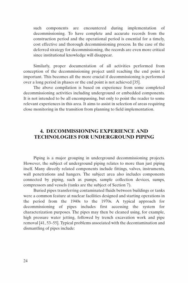
4. DECOMMISSIONING EXPERIENCE AND TECHNOLOGIES FOR UNDERGROUND PIPING
Piping is a major grouping in underground decommissioning projects. However, the subject of underground piping relates to more than just piping itself. Many directly related components include fittings, valves, instruments, wall penetrations and hangers. The subject area also includes components connected by piping, such as pumps, sample collection devices, sumps, compressors and vessels (tanks are the subject of Section 7).
Buried pipes transferring contaminated fluids between buildings or tanks were a common feature at nuclear facilities designed and starting operations in the period from the 1940s to the 1970s. A typical approach for decommissioning of pipes includes first accessing the system for characterization purposes. The pipes may then be cleaned using, for example, high pressure water jetting, followed by trench excavation work and pipe removal [41, 53–55]. Typical problems associated with the decontamination and dismantling of pipes include:
24

(a) Uncertainties about the exact piping routes and system connections due to lack of as-built drawings as well as other construction and various operational record keeping deficiencies.
(b) Uncertainties about the physical state of the piping walls and the possibilities for ongoing leakage which could render aggressive decontamination undesirable. See Ref. [55] for piping made of vitreous clay.
(c) Presence of difficult-to-decontaminate solid deposits, sludge or sediments often due to long dormancy periods and lack of proper maintenance — often complicated by a lack of injection points for decontamination chemicals.
(d) Difficult access for characterization, disassembly including preliminary removal of obstacles (Fig. 4) and removal of segmented pieces.
(e) Harsh working environments due to the presence of tight spaces, likelihood of heat stress, and/or high radiation/contamination levels requiring the use of personal protective equipment.
(f) Possible contamination of nearby components and/or structures and the soil due to leaking pipes, and uncertainties about the extent of peripheral remedial work which may be required (Fig. 5).
It should be noted that most of these issues are also relevant to the decommissioning of underground tanks and other underground or embedded components. The following sections describe the technologies and approaches that were developed to solve some of the above issues. A good deal of decommissioning technologies would be equally applicable in the decommissioning of components and structures described in Sections 7 and 8. Therefore, the focus in this section is on state of the art technologies that were developed for, or are particularly applicable to, decommissioning of piping. Additional detail is given in the technical literature, for example Refs [1, 2, 4, 5, 40, 41].
4.1. CHARACTERIZATION OF PHYSICAL, RADIOLOGICAL AND HAZARDOUS MATERIALS
An overview of innovative and emerging technologies is provided here. A number of these techniques were developed, deployed and optimized in actual decommissioning operations with funding from the United States Department of Energy to cope with the enormous legacy of redundant nuclear facilities in
25

the USA [29, 56, 57]. Specific technologies addressing contaminated piping, costs and technical performance resulting from their testing are discussed in Ref. [58].
Characterization of underground embedded piping can be difficult, time consuming and costly, particularly if the pipes extend for long distances (up to several kilometres is not unusual in older plants). A graded approach concept has been suggested and implemented in several decommissioning projects where some piping can be located in non-contaminated areas or may contain radionuclides that can be easily remediated in situ. The graded approach is
FIG. 4. Hot cell dismantling: removal of various embedded process systems for servicing the cell at the radioisotope production facility at Tunney’s Pasture, Ottawa, Canada. Courtesy: Atomic Energy of Canada Limited.
26

based on the concept that piping with a lower potential for contamination requires a less robust characterization plan than piping with a higher potential for contamination. A description of a logical process for graded characterization is given in Ref. [41].
4.1.1. Geophysical characterization objectives
A common issue at many old nuclear sites is that the location of and routes of underground piping are often uncertain or vaguely known at best. In some cases, records are simply missing, or actual field conditions do not match the available records. Typical underground lines that may be contaminated include sewers, waste lines, ventilation pipes, sumps and liquid discharge lines. Other items of interest include underground tanks and disposal pits, cables and services, buried objects and emplaced materials, and the position of cracks or fractures within concrete structures. As an example, a pre-decommissioning description of this issue for the Paldiski Nuclear Centre in Estonia is given in
FIG. 5. Removal of contaminated soil around the boiling water reactor (BORAX) turbine building at Idaho National Engineering Laboratory, Illinois, USA.
27

Refs [59, 60]. According to the Estonian operator, there are about 2030 m of active sewage lines (stainless steel) and 1500 m of ventilation pipes (carbon steel) underground [61, 62]. More examples are given in the following paragraphs.
A prerequisite to a piping decommissioning project is the identification of piping location and routes. As physical access to piping is often impractical (or even impossible) owing to obstructions or high radiation levels, remote techniques have been developed to locate underground piping and other components. Some techniques are described in Appendix II of Ref. [63]. One typical technique is the application of closed circuit television viewing systems for location [55]. Table 1 (an elaboration from Ref. [63]) lists some techniques and their typical applications. In general, all the techniques listed would be applicable to the entire scope of this report.
Characterization for dismantling necessarily addresses materials. The material most often used for construction of piping and related components is steel (carbon steel or stainless steel), although other materials such as plastic, concrete, ceramic and rubber are also used. The piping can be equipped with a coating (paint or bituminous tapes) or thermal isolation (mineral wool, asbestos, etc.), which can often be a hazardous material (asbestos, lead paints or paints with polychlorinated biphenyl (PCB)). The piping and auxiliary components may have been placed in concrete corridors or tunnels, sometimes with a steel lining or directly in the soil.
The geophysical characterization in this report emphasizes techniques of special importance to underground components; for example, geophysical methods for locating objects and non-destructive testing (NDT) for assessing material condition.
4.1.2. Geophysical characterization techniques
Geophysical characterization is of special importance for locating underground components and some sources of contamination. Table 1 provides a list of typical methods and references to their uses. In the example cited earlier of Paldiski, Estonia, ground penetrating radar, magnetometer and seismic techniques were suggested [62]. Reference [64] deals with the combined use of several characterization techniques.
4.1.3. Non-destructive testing
It is sometimes necessary to verify the integrity of underground or embedded components using NDT. This is intended to assess the SSCs for past or present leakage of contaminated fluids. It will also assist in the evaluation of
28

decontamination methods or possible loss of integrity of the components. Basic information on NDT can be found in Refs [77–79].
Non-destructive testing is a descriptive term used for the examination of materials and components without changing or destroying their usefulness.
The most commonly used NDT methods that are relevant to the topic are:
— Visual inspection;— Acoustic emission testing;— Eddy current testing;— Ultrasonic inspection.
4.1.3.1. Visual inspection
Visual inspection is the one NDT method used extensively to evaluate the condition or the quality of a weld or component.
For the purpose of inspection of underground structures, special devices may need to be utilized. Several applications for pipe inspection in the Czech Republic using closed circuit television cameras mounted on trolleys are described in Ref. [80] and are depicted in Figs 6 and 7.
TABLE 1. SUMMARY OF COMMON GEOPHYSICAL TECHNIQUES
Technique Application References
Seismic Geological structure, and lateral and vertical extent of landfills and trenches
[65]
Ground penetrating radar
Buried objects, geological structure and contaminants
[66–70]
Electromagnetic radiography
Detection of contaminants in soil [65, 71, 72]
Cone penetrometer tests
Sedimentary boundaries and contaminants [73–75]
Magnetic gradiometry
Buried metallic objects such as drums and tanks [65]
Electromagnetic induction
Buried objects, extent of landfills and trenches [65]
Electrical resistivity Geological structure, landfills and buried objects [65, 76]
Gravity and microgravity
Geological structure, landfills and buried objects [65]
29

In France, the Commissariat à l’Énergie Atomique (CEA) has developed a small device known as a cleaning head which can be used for cleaning and inspection of ducts. The device is capable of travelling inside the duct for distances up to 20 m propelled by compressed air via a flexible hose attached to the head [81].
FIG. 6. A pipe characterization trolley of type PVK-3, used in the Czech Republic.
FIG. 7. A pipe inspection and removal trolley of type PCK-60, used in the Czech Republic.
30
4.1.3.2. Acoustic emission testing
Acoustic emission testing (AET) uses ultrasound, usually in the range between 20 kHz and 1 MHz, generated by the rapid release of energy from the source within a material. The elastic wave propagates through the solid to the surface, where it can be recorded by one or more sensors.
The advantages of AET are that a whole structure can be monitored from a few locations, the structure can be tested in use (without taking it out of service) and continuous monitoring with alarms is possible. Microscopic changes can be detected if sufficient energy is released, and source location is also possible using multiple sensors.
Leaks in underground pipeline systems can be located using the characteristic sound waves generated by the flow of fluids (either liquids or gases) through a hole. Sound sensitive sensors placed along the length of the pipeline transform sound (mechanical) energy from the leak into electrical energy. In addition to providing indications of leaks, the leak location capability can provide precise information for decommissioning underground piping systems. The method has limitations, as a number of contact points are needed along the length of the pipeline for installation of sensors.
4.1.3.3. Eddy current testing
Eddy current testing is an electromagnetic technique that can only be used on conductive materials. It is used in applications that range from crack detection to the rapid sorting of small components for flaws, size variations or material variation. It is most commonly used in the aerospace, automotive, marine and manufacturing industries.
4.1.3.4. Ultrasonic inspection
Ultrasonic inspection uses sound waves of short wavelength and high frequency to detect flaws or measure material thickness. It has been used on aircraft, power station generating plant and welds in pressure vessels. It is a complex procedure, and considerable technician training and skill is required.
In addition to the methods described above, several other techniques such as coloured dye tracers, gas tracers and isotope tracers can be used for locating leaks in underground pipes. The coloured dye tracer technique has been successfully applied for locating leaks in underground pipes at a research reactor in India using a sodium fluorescent dye.
31

4.1.3.5. Non-destructive testing of concrete
Reference [82] describes several methods for NDT of concrete which could also be applicable for physical characterization of embedded piping, for example, electromagnetic, ultrasonic and ground penetrating radar methods.
4.1.4. Radiological characterization
The selection of a method for decommissioning of buried or embedded components depends on many factors. Characterization of radioactive contaminants is one of the most important factors [83]. It is important for the proper selection of decontamination methods, dismantling methods and management of radioactive wastes from decommissioning activities. The main characteristics of contamination are:
— Type of contamination (alpha, beta or gamma);— Level of contamination (high, moderate or low);— Adherence of contaminants to the material (loose or fixed).
In some instances, several conditions in a working area such as poor accessibility of underground or embedded piping or the presence of alpha contaminants may necessitate the use of special equipment to perform the characterization of an area. For several years the USDOE Deactivation and Decommissioning Focus Area has been developing, demonstrating and deploying innovative and improved technologies for facility characterization to reduce the costs associated with decommissioning activities. A summary of characterization technologies, with a focus on those developed by the USDOE, is presented in the remainder of this section [84].
4.1.4.1. Pipe Explorer devices
These devices are intended for characterization of pipes and drains. They are pneumatically operated tubular plastic membranes that transport various detectors or sensors (e.g. gamma detectors, beta detectors and video cameras) into contaminated piping systems. Historically this activity has been attempted using hand-held surveying instrumentation, surveying only the accessible exterior portions of pipe systems or resorting to costly excavation, measurement and disposition. Various measuring difficulties, including in some cases an inability to measure threshold surface contamination values and workerexposures, and physical access constraints have limited the effectiveness of traditional survey approaches. One way in which Pipe Explorer devices have
32

been particularly effective is their capability to demonstrate that buried pipes have not been contaminated and, therefore, could be left in place or removed using standard removal or demolition techniques. Pipe Explorer devices have been deployed at various decommissioning sites, for example, Mound Site, Trojan nuclear power plant, Idaho National Engineering and Environmental Laboratory (INEEL) [85] and the CP-5 reactor decommissioning project at Argonne National Laboratory (ANL) [86]. Figure 8 depicts the deployment method used for making measurements with Pipe Explorers. Further information on Pipe Explorer use and applications is given in Refs [57, 87–90]. A chronological listing of Pipe Explorer uses for piping characterization is given in Table 2 [91].
4.1.4.2. Pipe CrawlerTM devices
These devices consist of a wheeled platform on which is mounted an array of thin Geiger–Müller detectors. They are moved manually directly through piping systems; a detailed description can be found in Ref. [92]. In planning the decommissioning of Shoreham nuclear power station, New York, it was determined that the cost of removing contaminated floor drain piping was prohibitive. The piping is typically embedded approximately 4 ft (1.2 m) deep in reinforced concrete, often below structural I beams. A decision was made to develop Pipe Crawler devices that would allow the plant to be decontaminated
FIG. 8. Science and Engineering Associates’ Pipe Explorer™ system deployment sequence (1 psi = 703 kg · m–2, 1 ft = 0.3048 m). Courtesy: INEEL
33

TABLE 2. CHRONOLOGICAL LISTING OF SITES USING THE PIPE EXPLORER TECHNOLOGY [91]
Site/date of useType of piping/
applicationTypes of survey
INEEL (reactor facilities), July 1994 Scrap piping Gamma (Cs-137)
Adrian, MI (private industrial site), April 1995
Buried oil drainagepipes
Beta (U-238)
Inhalation Toxicology Research Institute (research lab.), November 1995
Buried drain pipes Beta (Sr-90)Gamma (Cs-137)Video
USDOE, Grand Junction Projects Office (uranium mill pilot plant), February 1996
Buried drain pipes Beta (U-238)Video
ANL, CP-5 reactor (reactor facilities), August 1996
Storm drain, ventilation ducts and fuel rod storage tubes
Alpha (Am-241)Beta (Sr-90)Gamma (Cs-137)Video
USDOE Mound Facility (tritium facility), November 1996
Buried radioactive waste drain pipes
Gamma (Co-60)Video
Trojan (nuclear power plant), November 1997
Clean radioactive wastes, dirty radioactive wastes and auxiliary building radioactive wastes
Gamma surveys (Co-60)
Los Alamos National Laboratory (energy R&D laboratory), August 1998
Landfill characterization
Gamma spectroscopy
Savannah River Site (plutonium production site), September 1999
Storm and process drain pipes
Beta (Sr-90)
Battelle Columbus Laboratory, King Avenue and West Jefferson sites (nuclear R&D), December 1999 and January 2000
Storm and process drain pipes
Beta and gamma
Brookhaven National Laboratory (reactor R&D), August 2000 and September 2001
Piping Beta and gamma
Rocky Flats plant (plutonium facility), July 2001
Ventilation ducts Alpha
Maine Yankee (nuclear power plant), September 2002
Piping Gamma
34

and embedded piping to be surveyed. It was reported in Ref. [87] that Pipe Explorer devices may have significant advantages over Pipe Crawler devices, including higher speed, ability to negotiate obstructions, wider range of pipe diameters, being steerable and prevention of cross-contamination. Pipe Crawler was extensively tested at the CP-5 reactor decommissioning project [86] and Park Township sites [57]. The development of a similar Pipe Crawler system and the results of a specific application at Savannah River Site are described in full detail in Ref. [93]. Another application is described in Ref. [94]. Further experience, costs, strengths and limitations of this system are given in Ref. [95]. A similar technology, named BTX-II, was demonstrated at the USDOE Fernald facility [96].
4.1.4.3. Alpha contamination measurements
Direct measurement of alpha contamination inside pipes is difficult since alpha particles have a very short range in air. Therefore, indirect measurement methods are often used. Just such a technology is that of the IonSens monitors that were used to measure alpha contamination in pipes that have inaccessible surfaces at the USDOE Savannah River Site in a fuel fabrication facility [97]. Detectors based on the long range alpha detector (LRAD) technology have been developed at the Los Alamos National Laboratory in the USA. The LRAD technology measures alpha contamination by detecting the ions produced in a gaseous medium by alpha particles rather than by detecting the alpha particles themselves. The advantage of LRAD technology is that, unlike conventional detectors, LRAD based instruments do not need to be in close proximity to the alpha sources to provide a sensitive measurement. Monitors were designed and built especially to detect contamination in pipes [98–101]. An electret1 ion chamber (EIC) has been used to measure contamination inside 150 mm diameter pipes. An EIC consists of an electret loaded into an electrically conducting plastic chamber of a known air volume and a charge reader. As the result of the collection of ions on the electret’s surface, its surface charge diminishes. This reduction in charge over a known time interval provides a quantitative measure of the radiation. This technology is described in detail in Ref. [102]. Additionally, alpha measuring capabilities have been developed for use with the Pipe Explorer devices [86, 97, 103, 104].
1 An electret is a solid electrically insulating, or dielectric, material that has acquired a long lasting electrostatic polarization. Electrets are produced by heating certain dielectric materials to a high temperature and then letting them cool while immersed in a strong electric field. An electret is an analogue of a permanent magnet.
35

4.1.4.4. Subsurface contamination measurements
A typical problem with radiological characterization of underground pipes is the possibility of past leakage and contamination of the surrounding soil. An interesting application of innovative technologies to solve this problem is given in Ref. [105]. During operation of the Brookhaven graphite research reactor (BGRR), the below ground exhaust air ducts provided passage of the cooling air flowing through the graphite reactor pile to the exhaust stack. Following reactor shutdown, the ducts accumulated water and were a potential source of contamination to the soils beneath the facility. Thorough subsurface soil characterization was required to determine the location and extent of potential contamination, to facilitate appropriate remedial action planning. The innovative technologies selected included the use of a small geoprobe to install sampling ports in the soil and beneath the buildings and the use of gas tracers to define the leak pathways. Additionally, three dimensional (3-D) visualization tools were used to analyse the collected data, an in situ object counting system (ISOCS) was used for rapid field gamma surveys of soil samples, and the BetaScint technology, a fibre optic sensor, was used for beta surveying of soil samples.
Reference [63] provides a general review of soil contamination measurement techniques. In particular, radiation sensors in conjunction with computer programmes are available that correlate surface readings with underground contamination.
4.1.5. Characterization of hazardous constituents
In addition to the physical and radiological characterization of underground pipes, tanks and other components, other analyses are recommended to:
— Quantify the industrial hazards to be encountered;— Determine the most appropriate measures for the protection of workers
and the environment;— Select the most suitable cutting tools and decontamination processes;— Segregate metal wastes, including painted metal, before recycling.
Analyses to detect the presence of heavy metals or other biological or chemical contaminants are also essential. This is an important consideration in some Member States in which regulatory requirements restrict the handling and disposal of some of these materials. It is also an important consideration in
36

understanding how to properly protect the workforce performing the decommissioning activities.
The current method used is to collect samples and to analyse the samples in qualified laboratories. However, this method is not always the most economical and feasible due to the absence of a large number of qualified laboratories in the vicinity or other constraints. Therefore, the use of in situ real time analysers can be very useful and cost effective.
A few examples of these types of technologies are given in the remainder of this section.
4.1.5.1. Lead paint analysers
Lead paint analysers are battery operated hand-held analysers. They use X ray fluorescence (XRF) spectrum analysis to identify and quantify the presence of heavy metals and elements in finished surfaces of walls and floors. Twenty-five elements can be characterized in about 20 seconds. The output is in mg/cm² and depending on the application may require conversion into different units. The analysers can detect 24 different heavy metal or chemical contaminants [72].
4.1.5.2. Multielement analysers
Multielement analysers are another type of battery operated hand-held analyser. They also use the XRF spectroscopy to quantify elements in metals and determine the specific alloy in metallic materials. The readings are expressed in percentage by weight and compared with a built-in library to identify the alloy. Measurements are performed and the results provided in about 20 seconds [72].
4.1.5.3. Flow probe chemical analysers
Flow probe chemical analysers are a flowing reagent system in which analytes diffuse across a membrane into a vessel containing a reagent. A chemical reaction between the reagent and the analyte then produces a spectrally distinct product. The absorption characteristics of the products are measured by illuminating the reaction volume with broadband white light. Using optical fibres, this light is carried from a flash lamp to the reaction volume and then to a small solid state spectrometer. The targeted contaminants are metallic ions in aqueous matrices and volatile organic compounds (VOCs) in aqueous matrices and in ambient air [106].
37
4.1.5.4. Field deployable VOC analysers
Field deployable VOC analysers are based on available infrared photoacoustic gas analysis modules. One of these modules uses filters to monitor infrared absorption in narrow wavelength ranges and thereby measure up to five target gases (plus water vapour), and the other contains a complete Fourier transform spectrometer to provide a full mid-infrared spectrum. Various modules are combined to form a complete analyser system. Sampling and sample preparation modules are also available. These provide automatic gas sampling from several points, preparation of soil and water samples for VOC measurement by the gas analysers, or interfacing to deployment and retrieval systems such as cone penetrometers. This is an active research and development area. One application is shown in Ref. [107].
4.2. CUTTING AND REMOVAL
The available technologies for cutting metallic materials can be grouped into two broad categories: thermal cutting and mechanical cutting. A discussion of the advantages and disadvantages of both categories is given in more detail in Refs [2, 107]. More generic dismantling technologies are described in detail in Refs [1, 2, 4]. Typical applications in the cutting of piping and tanks are given in Table 10.1 of Ref. [2], including, inter alia, limitations due to piping and tank diameters, environment, material, thickness and secondary wastes. Prior to removing the piping it is often necessary to perform preparatory activities such as asbestos removal or even isolation of the piping for some period either until a work plan can be developed and approved for implementation or the actual implementation itself can be facilitated.
4.2.1. Preparations for work
Often before any work can be started on piping removal, it is necessary to perform some precursor activity or preparation of the work area or workpiece for cutting, for example, removal of insulation materials or isolation of the systems. These preparatory activities can be very time consuming and can often require the greatest fraction of the time, even more than that taken in performing an actual item of work activity. Several examples of these types of preparation can have an impact on embedded or buried component removal activities. Often, older piping systems were insulated with asbestos pipe insulation. In some other cases it is difficult to find a method to isolate the piping so that cutting or removal operations can be undertaken on it.
38

4.2.1.1. Asbestos removal
Nearly all of the steam and process piping systems in many of the older nuclear installations are clad and insulated with asbestos containing materials (ACMs). Manual removal of ACMs is very labour intensive and expensive but a prerequisite to the regulatory requirements for further decommissioning activities to commence. Current manual removal methods require substantial infrastructure for scaffolding, containment areas and air monitoring, which often results in poor asbestos removal production rates.
An innovative mechanical asbestos removal system, dubbed BOA, was developed for the USDOE. BOA can be remotely placed on the outside of the pipe, can crawl along the pipe, wetting the ACMs, encapsulating and stripping the pipe, and bagging the removed insulation. Careful attention to vacuum and entrapment airflow ensures that the system can operate without a containment area while meeting standards for fibre count. The BOA asbestos removal head is placed on the insulated pipe with the assistance of a labourer, while another operator controls the robot via a remote control pendant. BOA cuts through various types of insulation cladding, such as plaster tape, aluminium lagging, wire mesh, plastic boots and pipe clamps. Lagging and insulation are cut using a hybrid endmill and water-jet cutter. The diced sections are removed from the pipe using a set of blasting fan-spray nozzles, and removed through a vacuum hose. The off-board HEPA vacuum collection system contains asbestos fibres by drawing a vacuum on the entire removal module. A separate fluid system provides sealant to spray the stripped pipe with an encapsulating material [109].
4.2.1.2. Pipe isolation and cleaning
Tanks at the USDOE Oak Ridge National Laboratory were once used for storage of liquid radioactive wastes. During rainstorms and for several days afterwards, groundwater leakage through pipes connected to these tanks posed a problem in that, since groundwater had entered the tanks, it now required processing as radioactive waste. These tanks clearly needed to be isolated to prevent groundwater from leaking into them after retrieval activities on the tanks had been completed. In the past, tanks were isolated by hand excavation and plugging of pipes from the exterior of the tanks. This method is complicated by the lack of reliable methods to determine the exact location where piping enters tanks, the potential for worker contamination and significant quantities of wastes that must be treated and disposed of.
The USDOE Tanks Focus Area developed an improved method for, and tools associated with, the plugging of pipelines from inside the tank. A pipe
39

cutting and isolation system was successfully deployed at the ORNL South Tank Farm in 1998 and 1999. While cost savings were achieved, the primary driver for this deployment was reduced worker radiological exposures. The pipe cutting and isolation system comprises three new tools developed for use inside a tank to seal pipes. The new approach to tank isolation involves the following tools for the indicated task:
(a) Pipe cutting tool — This cuts pipes as needed in preparation for pipe plugging. Vertical pipes require cutting to access the ends of the pipes.
(b) Pipe cleaning tool — This cleans pipes as needed to remove scales and deposits from outside and inside pipe ends.
(c) Pipe plugging assembly — This plugs pipes as needed to provide a seal against groundwater intrusion [110].
One special problem is pipes clogged by accumulated solids. Overpressurizing a pipe to attempt blockage removal is a common method, but often unsuccessful and undesirable. Other invasive methods include sewer snakes and water jetting. While these methods can be effective, they can also create a significant problem with contamination cleanup and personnel exposure. However, the experience of the UK (Annex V) indicates satisfactory application of water jetting there. A pulsed hydraulic system has been developed which uses the differences between the resonant vibrations of the fluid column and pipe walls to separate the blockage from the pipe wall, break the blockage up and clear the line [111].
4.2.2. Thermal cutting
The most common thermal cutting techniques are plasma arc cutting, oxyacetylene cutting, oxygasoline cutting and oxygen burning bars. Under some circumstances, thermal cutting techniques are economically and technically desirable methods for dismantling piping systems. These techniques have been used for many years and are known for the speed with which material can be cut by using them. In addition, relatively low cost and ready availability of the equipment, as well as the availability in the workforce of operators familiar with them, are advantageous. However, there are also disadvantages. Thermal cutting techniques generate a great deal of heat, high temperature wastes and airborne contamination. These airborne contaminants, both gaseous and particulate, necessitate respiratory protection of the operator against the possibility of inhalation. Post-operation cleanup and remediation is required if airborne contamination or particles are generated. Experiences from German development programmes with underwater thermal cutting
40

indicate good success by which some of the drawbacks of open air thermal cutting can be avoided [112, 113]. Underwater thermal cutting has been applied to the decommissioning of several nuclear power plants. It is worthy of consideration for applications to underground tank size reduction.
4.2.3. Mechanical cutting
The mechanical cutting techniques use cold cutting processes for material removal. Common techniques of this type include mechanical sawing, water-jet techniques and machine cutting. These techniques offer many advantages, such as reduced generation of heat, lack of high temperature waste material and a very low likelihood of airborne contamination. Saws are typically limited to smaller pipe sizes, but in suitable applications can be economical and reasonably fast, though slower than thermal techniques (Fig. 9). Water-jetcutting offers good cutting speed but it generates a large volume of liquid waste (containing metal and abrasive particles) that requires appropriate conditions for treatment and disposal. Collection of wastewater can complicate waste operations and offer the possibility of the spread of contamination. Machine cutting techniques include milling cutters and portable lathes (Fig. 10). Machine cutting is typically characterized by a high degree of precision, low
FIG. 9. Cutting of pipes using a bandsaw at the JPDR (Japan Power Demonstration Reactor) commissioning project, Japan. Courtesy: Japan Atomic Energy Research Institute.
41

particulate contamination of the work area, wastes that are easily contained and collected for disposal, and low generation of airborne contaminants.
In parallel with the successful development of characterization technologies, the Science and Technology Program of the USDOE Office of Environment Management has also addressed cutting technologies. A few are typically targeted at the dismantling of piping and are highlighted later in this section. Summary cost and performance data for techniques developed and tested under the USDOE programme are given in Ref. [29]. Refs [40, 114, 115] give, inter alia, ranking matrices for cutting techniques as applied to instrument tubing, small diameter piping and large diameter piping.
FIG. 10. Cutting reactor head standpipes using an orbital cutter with a lathe at the BR-3Mol decommissioning project, Belgium. Courtesy: Studiecentrum voor Kernenergie –Centre d’Étude de l’Énergie Nucléaire (SCK·CEN).
42
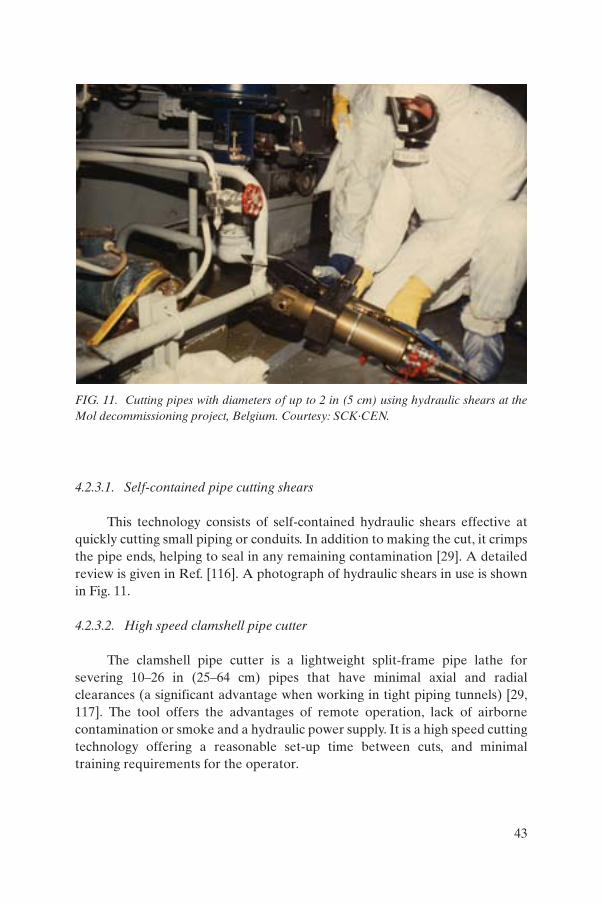
4.2.3.1. Self-contained pipe cutting shears
This technology consists of self-contained hydraulic shears effective at quickly cutting small piping or conduits. In addition to making the cut, it crimps the pipe ends, helping to seal in any remaining contamination [29]. A detailed review is given in Ref. [116]. A photograph of hydraulic shears in use is shown in Fig. 11.
4.2.3.2. High speed clamshell pipe cutter
The clamshell pipe cutter is a lightweight split-frame pipe lathe for severing 10–26 in (25–64 cm) pipes that have minimal axial and radial clearances (a significant advantage when working in tight piping tunnels) [29, 117]. The tool offers the advantages of remote operation, lack of airborne contamination or smoke and a hydraulic power supply. It is a high speed cutting technology offering a reasonable set-up time between cuts, and minimal training requirements for the operator.
FIG. 11. Cutting pipes with diameters of up to 2 in (5 cm) using hydraulic shears at the Mol decommissioning project, Belgium. Courtesy: SCK·CEN.
43

4.2.4. Technique evaluation and selection
A major consideration in selecting cutting techniques [108] for pipes is whether the cuts should be made in situ or ex situ in a dedicated workshop. It is assumed that some cutting activities are required to be performed in situ owing to the need to readily handle and transport segmented pieces to the storage or treatment station. Another essential point is accessibility, depending on whether and to what extent obstructions were removed prior to dismantling being required. The most difficult case is that of piping embedded in concrete or located in tight crowded tunnels and ducts [118].
Thermal cutting is typically best suited where the piping to be cut is not contaminated with radioactive or other hazardous material, is not painted or coated with hazardous materials, and is not in a location where the high temperature particulate waste will pose a contamination or recovery and/or cleanup problem. The primary reasons to use thermal cutting techniques are speed, low cost and lower risk of environmental contamination or worker exposure issues.
When working with piping that has been painted or coated (for example lead based paints), thermal cutting is only advisable after the removal of the paint or coating (which can be a costly and time consuming process). In fact, the cutting requirements may prevent the use of paints or coatings, which may have some advantages in decommissioning (Section 5.4). Mechanical cutting complements thermal cutting when the latter is not feasible. When pipes are painted or coated an option is to cut without removing paint or preparing the pipe in any way. Additionally the restricted wastes that are generated are minimal, and are easily collected and eliminated. The need to work in restricted quarters seems to be a strong argument for the use of cold cutting techniques.
4.3. SELECTED EXPERIENCE IN DISMANTLING OF PIPING
Decommissioning projects involving underground and/or embedded piping are commonly small parts of larger decommissioning projects. However, in some instances perhaps only a smaller part of a facility or smaller facility undergoes decommissioning. Information on pipe dismantling is difficult to identify and sporadic. The following examples present a few selected cases.
As described earlier, the USDOE INEEL site was the host to a large scale demonstration project for testing of innovative decommissioning technologies. For the purposes of this report, it is worth noting the decommissioning of the Test Reactor Area (TRA) filter pits. The TRA engineering test reactor included facilities that tested gas cooled reactor
44

systems. Activated charcoal filters and delay tanks (all below ground) connected by a network of pipes, tunnels and trenches were used to process exhaust gases. Selected decommissioning technologies are described in Ref. [85]. Other decommissioning activities involving underground pipes at INEEL are described in Ref. [119].
Decommissioning of the Industrial Waste Treatment Plant (Building 34) at ANL, Argonne, Illinois, is relevant to this subject. Upon locating the first tank inlet pipe, which was only a few feet (a metre or so) underground, it was decided to trace it back to where it had originated in a nearby building, which had been demolished several years earlier. This pipe run was only about 40 ft (12 m) long but as excavation activities approached what was thought to be the end of the pipe run, the soil underneath the piping was found to be grossly contaminated. This resulted in the handling of large quantities of additional radioactively contaminated soils. This is not an unusual problem to be encountered in dealing with decommissioning of SSCs. Other details on piping and soil characterization and removal in this project are given in Ref. [120].
Another ANL project involving excavation and removal of underground piping and disposal of all materials (piping and soil) identified as radioactive wastes is described in Ref. [121]. A pneumatic transfer tube system was used to transfer irradiated fuel specimens and other samples between two research buildings. The below ground portion of the transfer system consisted of a 2.125 in (5.4 cm) outside diameter copper tube and an accompanying conduit for interconnecting electrical controls. The system ran approximately 1850 ft (564 m). The below ground tubing was in a trench approximately 4 ft (1.22 m) deep which followed the elevation contours of the area through which it passed. The work crew first flattened or crimped the tube at various intervals using a hydraulic crimper. The tube was then cut in the middle of each crimped area using a hydraulic cutter tool (Fig. 12). The tube ends were then taped over and further size reduced as needed for placement in the waste packages for shipment and disposal. A lesson learned from this project is presented in Annex X. Another ANL project involved the removal of 76 rod storage tubes to a full depth of approximately 15 ft (4.5 m). After a series of incidents and malfunctions due to inaccurate drawings and material data, only part of the tubes could be removed and another part was filled with concrete and left in place. The story is described in Ref. [122].
The ability to aggressively decontaminate to clearance levels, verify the effectiveness of this and document that the items were releasable (such as contaminated piping systems) were major concerns during the Fort St. Vrain (FSV) decommissioning project. The problem was especially acute for small bore piping. In this project more than 24 000 ft (7315 m) of piping was
45

decontaminated and 6200 ft (1890 m) was radiologically surveyed [123]. This included systems with a large amount of piping embedded in concrete. Commercially available piping detectors were limited, with restricted applications at FSV. Therefore the survey plan included modification of existing detector designs and the development of new survey instruments and methods [124]. For decontaminating the piping, processes used included grit blasting, abrasive blasting and high pressure water washing.
For grit blasting, the standard hose delivery system provided easy access and deployment and a controlled decontamination process. The blast nozzles were modified and fitted into carrier harnesses that transported the hoses through the pipe and permitted a full coverage, 360º surface blast for the entire length of the pipe piece. The pipe ends were sealed to provide a closed system, and a vacuum recovery system was attached to allow the blast media to be collected and reused. It should be noted that the FSV project did not benefit from more recent developments, for example Pipe Explorer described in Section 6.1.4.1 [123]. A special problem at FSV was the embedded pipes that exceeded release levels (typically at pipe elbows and welded joints) even after
FIG. 12. Dismantling of a buried pipe using hydraulic cutters at the ANL pneumatic transfer tube project, Argonne, Illinois, USA. Courtesy: Argonne National Laboratory, managed and operated by the University of Chicago for the USDOE under Contract No. W-31-109-ENG-38.
46

repeated decontamination attempts. A proposal was developed and accepted by the regulator to raise the release criteria for such pipes and to grout them in place. Justification for the elevated or increased release criteria is based on an as low as reasonably achievable (ALARA) analysis that demonstrates minimum public exposure if the piping is grouted in place [125].
At Trojan nuclear power plant, one activity that has a potential for making significant financial and schedule impacts on the overall decommissioning project is again the decontamination and survey of contaminated embedded piping. Trojan has about 29 000 ft (8800 m) of embedded contaminated piping in the reactor complex. Included in this piping are various drain systems, embedded ventilation ductwork, buried process piping and embedded conduits. Complete removal of the affected embedded piping would result in a substantially increased cost due to structural considerations and the depth of embedment. Therefore, Trojan is attempting to decontaminate and survey in place the bulk of the piping such that it will meet site release criteria. The scope of the Trojan Embedded Piping Project is extensively described in Ref. [126]. The strengths and weaknesses of various decontamination techniques (hydrolasing, media blasting and chemical decontamination) are compared with each other and with the removal of piping alternatives.
A mobile system that automatically cleans and characterizes piping is described in Ref. [127]. The system used grit blasting to remove paint and radioactive contamination from piping. Some 10 000 lb (4500 kg) was successfully cleaned at the Big Rock Point decommissioning project [127].
Remediation of subsurface radioactively contaminated drain pipes at the General Motors site in Adrian, Michigan, USA, is also noteworthy. This old Manhattan Project uranium handling facility, including pipes, drain pipes and sumps, was highly contaminated with 238U. Because the plant was actively operating and operations could not be shut down for remediation, traditional remediation by excavation and removal could not be conducted. Instead, the drain pipes were cleaned using Hydrolaser, a cleaning system with high pressure water-jets. The high pressure force exerted on the drain pipes caused it to propel its stream of abrasive media through 4 in (10 cm) drain pipes to distances greater than several hundred feet (over 100 m) while blasting the dried depositions adhering to the pipe walls. After the drain pipes were pressure washed, verification surveys were performed using the Pipe Explorer technology [128].
Another recent project included decommissioning of embedded items such as wells, hot drain pipes and HEPA ducting. The specific project was the decommissioning of the General Atomics Hot Cell Facility at the company’s main site near San Diego, California. All structures were removed and shipped
47

for disposal. The drains were encased in concrete and were removed by cutting into sections with the concrete in place being used for shielding from the high radiation levels. Cleaning of the drains was avoided by characterization and packaging of the items directly into waste boxes [83].
Another case, from Germany, of removal of embedded piping is shown in Fig. 13. Core drilling was performed around the pipe circumference in the embedment through the wall thickness so that the pipe could be easily removed without damaging the wall structure.
An old project, but one fully relevant to the scope of this report, is the decommissioning of the Intermediate Level Waste (ILW) transfer line at Oak Ridge National Laboratory. This line was an integral part of the liquid waste disposal system and operated from 1952 until 1975. It was constructed of 5 cm diameter steel pipe with neoprene joint gaskets, buried at a nominal depth of 1 m. Owing to the presence of contaminated soil at two former leak sites along the line, and the potential for radionuclide migration, decommissioning of the ILW line was given a high priority. A portion of the line was removed, and the two leak sites entombed. The remainder of the transfer line was left intact in the original abandoned condition. One interesting detail was that no vehicle access existed at several parts of the site, so construction of an access road was a prerequisite to project execution. A comprehensive review of the project is given in Ref. [129].
FIG. 13. Segmentation of a steam converter embedded pipe.
48
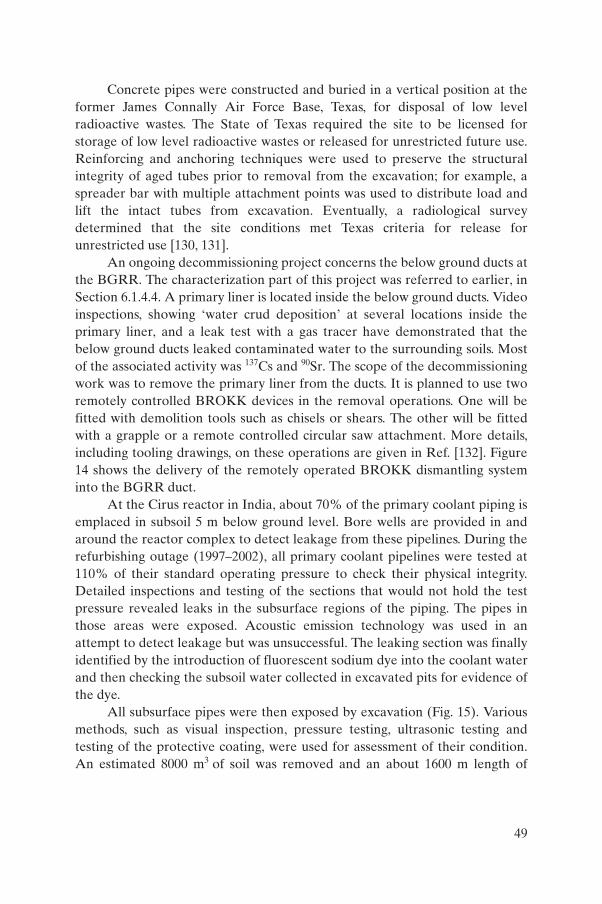
Concrete pipes were constructed and buried in a vertical position at the former James Connally Air Force Base, Texas, for disposal of low level radioactive wastes. The State of Texas required the site to be licensed for storage of low level radioactive wastes or released for unrestricted future use. Reinforcing and anchoring techniques were used to preserve the structural integrity of aged tubes prior to removal from the excavation; for example, a spreader bar with multiple attachment points was used to distribute load and lift the intact tubes from excavation. Eventually, a radiological survey determined that the site conditions met Texas criteria for release for unrestricted use [130, 131].
An ongoing decommissioning project concerns the below ground ducts at the BGRR. The characterization part of this project was referred to earlier, in Section 6.1.4.4. A primary liner is located inside the below ground ducts. Video inspections, showing ‘water crud deposition’ at several locations inside the primary liner, and a leak test with a gas tracer have demonstrated that the below ground ducts leaked contaminated water to the surrounding soils. Most of the associated activity was 137Cs and 90Sr. The scope of the decommissioning work was to remove the primary liner from the ducts. It is planned to use two remotely controlled BROKK devices in the removal operations. One will be fitted with demolition tools such as chisels or shears. The other will be fitted with a grapple or a remote controlled circular saw attachment. More details, including tooling drawings, on these operations are given in Ref. [132]. Figure 14 shows the delivery of the remotely operated BROKK dismantling system into the BGRR duct.
At the Cirus reactor in India, about 70% of the primary coolant piping is emplaced in subsoil 5 m below ground level. Bore wells are provided in and around the reactor complex to detect leakage from these pipelines. During the refurbishing outage (1997–2002), all primary coolant pipelines were tested at 110% of their standard operating pressure to check their physical integrity. Detailed inspections and testing of the sections that would not hold the test pressure revealed leaks in the subsurface regions of the piping. The pipes in those areas were exposed. Acoustic emission technology was used in an attempt to detect leakage but was unsuccessful. The leaking section was finally identified by the introduction of fluorescent sodium dye into the coolant water and then checking the subsoil water collected in excavated pits for evidence of the dye.
All subsurface pipes were then exposed by excavation (Fig. 15). Various methods, such as visual inspection, pressure testing, ultrasonic testing and testing of the protective coating, were used for assessment of their condition. An estimated 8000 m3 of soil was removed and an about 1600 m length of
49

primary coolant pipes was inspected. A plan was drawn up and implemented for the replacement of the protective coatings, the elastomer gaskets, all the couplings and the leaking pipelines. The soil around the leaking section was found to be contaminated.
Sample pieces of pipe were removed and characterized to determine the extent and type of contaminants present. Radiation surveys also provided information on the extent and location of deposits. Trials of mechanical cutting
FIG. 14. Lowering of the remotely operated dismantling device (BROKK) into the BGRR duct, Brookhaven, New York, USA.
50
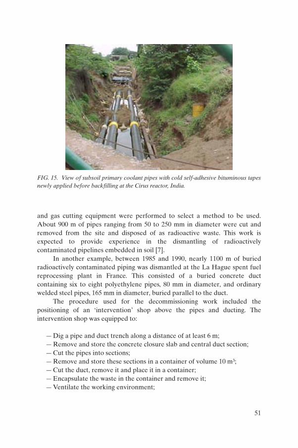
and gas cutting equipment were performed to select a method to be used. About 900 m of pipes ranging from 50 to 250 mm in diameter were cut and removed from the site and disposed of as radioactive waste. This work is expected to provide experience in the dismantling of radioactively contaminated pipelines embedded in soil [7].
In another example, between 1985 and 1990, nearly 1100 m of buried radioactively contaminated piping was dismantled at the La Hague spent fuel reprocessing plant in France. This consisted of a buried concrete duct containing six to eight polyethylene pipes, 80 mm in diameter, and ordinary welded steel pipes, 165 mm in diameter, buried parallel to the duct.
The procedure used for the decommissioning work included the positioning of an ‘intervention’ shop above the pipes and ducting. The intervention shop was equipped to:
— Dig a pipe and duct trench along a distance of at least 6 m;— Remove and store the concrete closure slab and central duct section;— Cut the pipes into sections;— Remove and store these sections in a container of volume 10 m³;— Cut the duct, remove it and place it in a container;— Encapsulate the waste in the container and remove it;— Ventilate the working environment;
FIG. 15. View of subsoil primary coolant pipes with cold self-adhesive bituminous tapes newly applied before backfilling at the Cirus reactor, India.
51

— Remove (when necessary) contaminated soil from the bottom of the excavation.
Further details are given in Ref. [133].Few pipelines used for discharging of contaminated liquids into the
environment have been removed, as these were laid in both public and private areas. One example is given in Annex I (Belgium), and other projects are described in Refs [134, 135].
4.4. WORKER PROTECTION
The use of protective clothing and respiratory protection is common in many nuclear decommissioning operations. Reference [136] provides guidance on both their selection and use. Wearing cumbersome protective clothing and/or equipment during physically demanding work can hinder the ability of a worker to remain productive. This is particularly relevant in decommissioning activities involving long stays in the situations addressed by this report in Sections 6–8. In particular, relevant aspects include ill ventilated environments, packed spaces, difficult access and lack of space in which to manoeuvre. A few innovative technologies were developed under the USDOE Environmental Management Programme and tested at the ANL, Fernald, Rocky Flats and Hanford sites [137]. Cost data are given in Ref. [29]. Selections of those systems are described as follows:
(a) Heat stress monitoring system — A heat stress monitor remotely analyses a worker’s physiological state through a series of sensors for core temperature, skin temperature, heart rate and motion. Associated software alerts the work crew supervisor or safety personnel to parameters that could indicate that a person is under undue stress. Further details are given in Refs [137–139].
(b) Personal Ice Cooling System (PICS) — PICS is a self-contained core body temperature control system that uses ordinary ice as a coolant and circulates the cooling water, via a rate-adjustable battery powered pump, through tubing that is incorporated into the garment. PICS has been proved to control heat stress, increase productivity, reduce dose exposures and improve worker comfort. Further details are given in Refs [85, 137, 140, 141].
(c) Advanced Worker Protection System — This is a self-contained breathing and cooling system designed to provide a worker with a two hour supply of air for breathing while simultaneously cooling the worker.
52

Cooling is provided for the worker as the liquid air vaporizes, and the vaporized air is then used for breathing by the worker. The vaporized air is also used to cool water that is circulated in a liquid cooling garment worn against the worker’s skin. Further details are given in Refs [56, 137, 142].
(d) Breathable coveralls — Progress in this field includes provision of protective clothing that is of lighter weight, waterproof, breathable and/or disposable (one time use), yet provides protection equivalent to that of current garments. Details about their characteristics are given in Refs [29, 137, 143, 144].
Continuous air monitors are often utilized near the work areas to provide samples and raise the alarm if high airborne radioactivity levels exist. Depending on conditions, workers may have to wear respiratory protection. In one project [121] respiratory protection was required to be worn when any individual was expected to work in airborne levels of radioactivity over 10% of the derived airborne concentrations (DACs).
5. DECOMMISSIONING EXPERIENCE AND TECHNOLOGIES FOR UNDERGROUND TANKS
Decommissioning of underground tanks has two major components. One is the removal of the liquid or solid wastes located in the tank. The second is the decontamination and dismantling of the tank itself and restoration of the contaminated soil areas. For both issues, physical accessibility is critical, and a further complication is the typical high radiation dose rates in the work areas from the tank and its contents. In many cases, the large physical size of these types of structures can also pose a problem in their management and eventual decommissioning. For all these reasons, remote operations have been developed and products are now commercially available that allow for easier tank access to facilitate characterization, decontamination and dismantling.
A special problem for waste storage in underground tanks can be the problem of waste contents removal from the tank itself. After many years of storage, the wastes may have separated into layers of liquid and sludge or even hard scale deposits. It is necessary to mobilize the heavy layer of sludge to remove it from the tank. An innovative method involves mixing the sludge with existing tank liquids rather than adding more liquids and increasing the waste volume. This approach produces slurry that can be more easily removed from
53
the tank [145]. As an example, millions of litres of radioactive liquid and sludge wastes require retrieval from underground storage tanks at some USDOE sites followed by transfer to a treatment facility and then processing into an acceptable final waste form. To retrieve wastes from storage tanks, sludge wastes are typically mobilized and mixed with liquid wastes to create a slurry of liquid and suspended solids. This slurry is then transferred by pipeline to the desired location for treatment prior to disposal. Slurries from retrieved tank wastes have high viscosity and solids content. Slurries with high viscosity are difficult to pump and generate large backpressures. If pump backpressures exceed the rating of the transport pipeline, pumping cannot continue. A pipeline blockage can occur because of gravity sedimentation of solids in the transfer line. Monitoring the transport properties (i.e. the percentage of suspended solids, density, viscosity, mass flow rate and particle size) of the slurries in transfer lines can prevent pipeline blockage and ensure safe transport of the wastes. In-line instruments provide real time measurements of slurry properties to operators, who can respond quickly to prevent any conditions that could lead to pipeline blockage [146]. Details of experience at some of the USDOE sites, among others, are given in Section 7.3.
It should be noted that many of the technologies discussed for piping are also relevant to decommissioning underground tanks, for which the details are not repeated here.
5.1. PHYSICAL AND RADIOLOGICAL CHARACTERIZATION
Many of the characterization techniques described for piping (Section 6.1) also apply to tanks. Because of the large dimensions of tanks compared with piping, more sophisticated instruments may be needed for characterization. Tank waste characterization technologies are not dealt with in this report.
5.1.1. Physical characterization
Owing to poor accessibility of underground tanks, access for characterization is a difficult and often cumbersome process. In addition, underground tanks frequently contain highly radioactive liquids or other waste materials, often requiring remote or semi-remote technologies to remove their contents. Traditional telescopic methods have limitations due to, for example, geometry or obstructions, but over the last few years a number of improved technologies have been developed worldwide. A selection of these is described in the following sections.
54

Methods used for physical characterization of piping (Section 6.1.1, Table 1) can also be used for physical characterization of tanks. Because of the dimensions of tanks, the device used for tank characterization need not be as small as for piping characterization, and more sophisticated instruments can be used. This is also valid for testing of the integrity of tanks (detection or assessment of the probability of leakages, loss of integrity, etc.).
5.1.1.1. The laser range finder and structured light mapping system
The laser range finder system consists of a laser, a receiver (such as a camera) and data processing equipment. For the structured light system, the position and direction of propagation of the laser beam is known and controlled. The camera shows the 2-D projected position of the beam on the surface to be mapped. Knowing that this position is the intersection of the laser beam with the object, one can perform simple trigonometric calculations to determine the position of the point in space [16]. This system was developed within the USDOE remediation programme and is a concept similar to the French device being used in Slovakia (Section 7.1.1.3).
5.1.1.2. Viewing systems for large underground storage tanks
As part of the USDOE large scale remediation programme, remote videos and photography systems have been developed for deployment in underground storage tanks [147]. The deployment required the use of a Light Duty Utility Arm [16, 148] and the development of video systems. There has also been the development of some remotely deployable technologies used for the Hanford Canyon Disposition Initiative (CDI) work performed only a few years ago [148].
5.1.1.3. Three dimensional laser modelling
At the A-1 nuclear power plant decommissioning project in Slovakia, the set of as-built facility drawings is not complete and in other cases has been found not to be 100% accurate. Owing to high radiation levels in the working areas, manual radiological characterization of these work areas is difficult and time consuming. Advanced technologies are being used to perform 3-D modelling of the A-1 nuclear power plant facility before planning the details for implementing the decontamination activities. A combination of 3-D laser scanning and the software 3Dipsos is being used for acquiring hard data on the arrangement of construction and equipment in these areas. Two laser-scanning range sensors are being used at the A-1 project. Soisic from Mensi of France (Fig. 16) operates on the triangulation principle at a rate of 100 discrete points
55

per second and has an operating range of 80 cm to 12 m. Callidus from Germany operates on the time-of-flight principle and has a range of 15 cm to 30 m. In either system, the measurements are presented as a cloud of (x, y, z) points. All measured points are transferred to the 3Dipsos software where a consolidation procedure brings all of the 3-D coordinates from different viewing positions into a common frame. After that, geometrical primitives (cylinders, cones, bends, planes, etc.) are fitted to operator chosen groups of points using a least squares adjustment algorithm. Finally, a 3-D model of the as-built scene is obtained. As-built modelling is currently used for the updating of the facility drawings, for example, the underground liquid waste storage tanks [149].
5.1.2. Radiological characterization
5.1.2.1. The GammaCam camera
The GammaCam, a gamma ray sensitive camera, superimposes radioactive hot spot data on video images of a facility. This device performed
FIG. 16. A 3-D laser scanner in use at the A-1 nuclear power plant decommissioningproject, Slovakia.
56
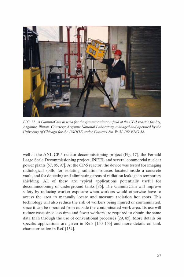
well at the ANL CP-5 reactor decommissioning project (Fig. 17), the Fernald Large Scale Decommissioning project, INEEL and several commercial nuclear power plants [57, 85, 97]. At the CP-5 reactor, the device was tested for imaging radiological spills, for isolating radiation sources located inside a concrete vault, and for detecting and eliminating areas of radiation leakage in temporary shielding. All of these are typical applications potentially useful for decommissioning of underground tanks [86]. The GammaCam will improve safety by reducing worker exposure when workers would otherwise have to access the area to manually locate and measure radiation hot spots. This technology will also reduce the risk of workers being injured or contaminated, since it can be operated from outside the contaminated work area. Its use will reduce costs since less time and fewer workers are required to obtain the same data than through the use of conventional processes [29, 85]. More details on specific applications are given in Refs [150–153] and more details on tank characterization in Ref. [154].
FIG. 17. A GammaCam as used for the gamma radiation field at the CP-5 reactor facility, Argonne, Illinois. Courtesy: Argonne National Laboratory, managed and operated by the University of Chicago for the USDOE under Contract No. W-31-109-ENG-38.
57

5.1.2.2. The Radscan imaging system
British Nuclear Fuels Ltd (BNFL) originally developed the Radscan gamma ray imaging system. It is designed to survey and plot data from large surface area surveys in order to identify radiological contamination. The resulting survey data describe how much contamination is present at exact locations without the previous large number of manned entries to collect these same data. Data can be permanently stored electronically and on videotape. The Radscan 600 technology was demonstrated at Hanford’s C reactor [155, 156]. Newer models of this unit are commercially available as Radscan 700 and 800.
5.1.2.3. ALADIN
This video gamma camera was developed by the French Commissariat à l’Énergie Atomique. ALADIN can be operated in two modes: hot spot detection or localization. The detection mode allows the camera to sweep the field of view while the PC monitor displays the real time colour video image and the periodically updated gamma image. Once a hot spot has been detected, localization of a source takes from five seconds to ten minutes, depending on irradiation level and intensifier tube gain [157]. Figure 18 shows the ALADIN camera in preparation for use at the A-1 nuclear power plant decommissioning project in Slovakia.
5.1.2.4. The Cartogam imaging system
As the commercial version of ALADIN, the Cartogam real time portable gamma ray imaging system is specially designed for gamma assays during maintenance and decommissioning operations on nuclear sites. This system provides quick localization of radionuclides within contaminated areas. After selection of both the area to be mapped and the acquisition mode (accumulation or counting), the operator starts the automatic sequence of acquisition. At the end of the exposure time, the system generates a composite image, consisting of the gamma mapping superimposed on the visible image by a transparency. The gamma image intensity is automatically normalized to the full scale; moreover, the digital associated values are corrected, thus offering scene-to-scene comparisons. The hot spots are evaluated in dose rate according to a user defined nuclide or spectrum [158].
58
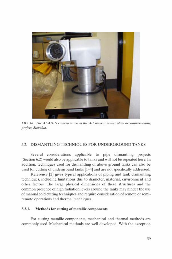
5.2. DISMANTLING TECHNIQUES FOR UNDERGROUND TANKS
Several considerations applicable to pipe dismantling projects (Section 6.2) would also be applicable to tanks and will not be repeated here. In addition, techniques used for dismantling of above ground tanks can also be used for cutting of underground tanks [1–4] and are not specifically addressed.
Reference [2] gives typical applications of piping and tank dismantling techniques, including limitations due to diameter, material, environment and other factors. The large physical dimensions of these structures and the common presence of high radiation levels around the tanks may hinder the use of manual cold cutting techniques and require consideration of remote or semi-remote operations and thermal techniques.
5.2.1. Methods for cutting of metallic components
For cutting metallic components, mechanical and thermal methods are commonly used. Mechanical methods are well developed. With the exception
FIG. 18. The ALADIN camera in use at the A-1 nuclear power plant decommissioningproject, Slovakia.
59

of cutting using explosives, these techniques produce easily handled secondary waste streams. They also produce much less airborne fumes than thermal techniques. They include:
(a) Saws — There are three main types of mechanical saw: reciprocating saws, band saws and circular saws. Mechanical sawing machines range in size from small hand-held saws to large industrial-scale saws such as band saws. Milling machines, which are different from saws, are also used in similar situations.
(b) Abrasive cutting wheels, blades, wires and core drills — These are electrically, hydraulically or pneumatically powered wheels, beads or chain links containing an abrasive held in a semi-rigid supporting matrix. Abrasive cutters can be used either dry or with a coolant, such as water, which is often recirculated to reduce secondary waste volumes.
(c) Shears — Shears can be manually, pneumatically, hydraulically or electrically actuated and are used for segmenting. Shearing produces no secondary wastes or wastes in the form of discrete sections, punched from the workpiece, which can be readily handled and retrieved. Shears can vary in size and weight depending on their intended application in the work to be performed.
Thermal cutting techniques are generally faster than mechanical techniques, the equipment is lightweight and the deployment system has only to accommodate small reaction forces during cutting as the tools do not require physical contact with the workpiece. The main disadvantage is the production of aerosols, dust and dross, which create issues of concern with respect to worker and environmental protection, visibility problems and large volumes of secondary wastes. Examples are:
(a) Plasma arc cutting — This is discussed in Section 6.2.(b) Flame cutting — Flame cutting is a well established technology and uses a
flowing mixture of a fuel gas (acetylene or propane) or fuel vapour (petrol) with oxygen or air, which are mixed and ignited to produce a high temperature flame.
(c) Thermic lances — A thermic lance consists of an iron pipe packed with a combination of steel, aluminium and magnesium wires through which a flow of oxygen gas is maintained. The lance cuts are achieved by thermite reactions at the tip of the lance in which all the constituents are consumed.
60

Sometimes abrasive water-jet cutting and electrical cutting techniques are used for such operations. Electrical cutting techniques are based on metal evaporation. These include:
— Electro-discharge machining;— Metal disintegration machining;— Consumable electrodes;— Contact arc metal cutting;— Arc saw cutting.
Special methods, such as laser or electron beam cutting, are still at a fairly early stage of the development process. There has been some recent progress in developing laser cutting by NUPEC in Japan [159]. Other research and development activities are given in Refs [1–4].
5.2.2. Concrete structures
For cutting concrete components both the mechanical and thermal technologies are available and commonly used. Some of the same cutting techniques used for metallic structures can also be used for cutting concrete structures:
(a) Saws — These encompass abrasive cutting wheels, blades, diamond wires and core drills.
(b) Expansive grouts — Non-reinforced concrete can be fractured by drilling holes and filling these with a wet grout mixture. As the grout cures it expands, creating internal stresses within the concrete substrate. Rebars (if present in the concrete) still pose a further dismantling problem in removing the concrete from the immediate area.
(c) Rock splitting — This is a method of fracturing rock or concrete by hydraulically driving a wedge shaped plug between two expandable guides into a pre-drilled hole.
(d) Paving breakers and chipping hammers — This is a conventional civil engineering method. These tools are widely used to remove concrete by mechanically fracturing localized sections of the surface.
(e) Abrasive water jet cutting — Water jets have the potential to contaminate clean areas if the water used is recycled through a contaminated collection volume.
Thermal cutting techniques (Section 7.2.1) for concrete include flame cutting and thermic lances.
61

5.3. SELECTED EXPERIENCE WITH TANK WASTE REMOVAL PROJECTS
As described earlier in this section the key issue associated with the decommissioning of underground tanks is the removal of wastes from the tank. Accordingly, this section consists of several examples of problems encountered and solutions found on this issue.
5.3.1. Waste removal in the USA
The West Valley Demonstration Project (WVDP) site is home to four underground storage tanks, two of which are 69 ft (21 m) in diameter, 26.9 ft (8.2 m) in height, and contain grid-work located on the bottom of each tank. These tanks were constructed in the 1960s to contain radioactive wastes generated during spent fuel reprocessing operations at the site. During retrieval campaigns between July 1996 and December 1999, long shafted mobilization (jet mixer) pumps were used to mobilize the bulk wastes in these two storage tanks. Transfer pumps were used to move 96% of the high level wastes (HLWs) to the WVDP vitrification facility. The storage tanks now contain residual solids from a tank sludge and zeolite ion exchange medium from vitrification operations.
Retrieval campaigns are using existing jet mixer pumps and a sluicing wand to mobilize wastes. For effective mixing, the mixer pumps require about 14 in (35 cm) of liquid in the tank. As a result, fewer wastes are retrieved with each batch removed from the tank. Alternative waste retrieval equipment may be needed if the cost to retrieve the residual wastes becomes excessive or the existing waste retrieval methods are unable to meet tank cleanup goals. In particular, technologies are needed for retrieval of wastes from tanks with obstructed access (due to the internal configuration of the tanks and the presence of internal structures). The Advanced Waste Retrieval System (AWRS) provides increased solids removal and transfer capability over that of the baseline method. This increased capability is the result of using a telescopic arm to place the suction pick-up within an inch (25.4 mm) or so of the tank floor and coupling the suction system to the existing transfer pumps for delivery of retrieved wastes from the tanks to the vitrification facility. The ability to move the suction pick-up to the wastes eliminates the need to mobilize the wastes with a mixer pump or sluicing wand. The AWRS was developed specifically for application at WVDP; however, components such as the telescopic arm and jet pump assembly as well as the grinder–separator assembly may have application for tanks at other USDOE sites with similar problems [160].
62

The USDOE is committed to removing thousands of cubic metres of high level radioactive wastes from 51 underground waste storage tanks at the Savannah River Site [161, 162]. The primary radioactive wastes are strontium, plutonium and caesium. It is recognized that the continued storage of these wastes is a risk to the public, workers and the environment. The Savannah River Site was the first site in a USDOE complex to have emptied and operationally closed a high level radioactive waste tank. The task of emptying and closing the remainder of the tanks will be completed by 2028. The wastes from each tank will be transferred to a waste pretreatment facility and then on to the Defense Waste Processing Facility, where they will be vitrified and poured into stainless steel containers. After waste removal, the interior of each tank is washed with water. Each tank is isolated physically by capping and sealing all pipes as well as cutting all electrical connections. Finally, the tank is filled with grout (there is a discussion of entombment in Section 7.4).
More details are given in the open literature on the decommissioning of Tank 19F. A hardened mass of solid waste material was identified at the bottom of this tank and was described as an hourglass shaped mound located in the centre of the tank. It is believed that a spray system comprised of a high pressure adjustable water nozzle used in previous tank closures may be able to break up the solid mass at the bottom of the tank. Once this takes place, agitators/mixers and pumps should be effective in removing the material from the tank [163].
The Nuclear Materials and Equipment Corporation (NUMEC) constructed a plutonium fuels manufacturing plant in Parks Township, Pennsylvania, in 1960. The process utilized an aqueous precipitation and calcination technique for the production of PuO2 powder. The plant included a dedicated wastewater collection and treatment system. These wastewaters were collected in two 1000 gal (3785 L) below ground concrete storage tanks. Following completion of the production operations in the early 1960s, the facility was deactivated; however, the below ground wastewater collection system remained in place with the inlet and outlet piping blanked off. Neither ownership changes and transfers nor reutilization of areas at the Parks Township facility disturbed the collection tanks, which remained unused and isolated for almost 30 years. Then in 1991, a decision was made to mobilize a project team to characterize and remediate these tanks. The radiological and chemical characterization of the tanks included the collection of samples of the tank contents as well as samples of the soil from beneath the tanks. No contamination was found in the soil and it was concluded that the two tanks had maintained their structural integrity. The selected remediation option included: pumping liquids from the tanks into drums, installation of rigging to lift and remove each tank, removal of the tanks using a crane and transfer of
63

the concrete tanks to a site building for dismantling [164]. A number of recent HLW tank decommissioning projects in the USA have required extensive development of robotic and remote handling capabilities. These are described in detail in Ref. [165].
The Mound Decontamination and Decommissioning program includes the Waste Transfer System (WTS) project. The WTS project consists of the removal of two underground service lines buried from 6 to 17 ft (2 to 5 m) below ground level as well as of Building 41, a one story concrete block above ground structure with a one story poured concrete basement 15 ft (4.5 m) below ground, which contained two storage tanks and a service pit. Reference [166] addresses decommissioning of Building 41. Several removal alternatives were analysed in depth, starting with no containment structure at all, through building a brick and mortar overstructure, to entombment. Studies resulted in a building of pole barn type being selected as the best alternative for meeting the containment criteria at a reasonable cost. The basement concrete and surrounding earth were removed, boxed and shipped for disposal. The steel tanks were size reduced with an acetylene cutting torch, boxed and shipped as transuranic waste.
5.3.2. Waste removal from the A-1 nuclear power plant in Slovakia
The A-1 nuclear power plant decommissioning project in Slovakia was commenced in 1999. One of the most important tasks is the preparation for decommissioning of the active water purification station (AWPS). The presence of radioactive materials and high radiation levels in certain areas limit the ability of personnel to access the underground storage tanks and rooms of the AWPS. Therefore, it was deemed necessary to use remotely operated manipulators for the characterization, decontamination and dismantling activities in the area [167]. The general purpose manipulator MT-80 is a five degrees of freedom hydraulic arm with a 1.8 m reach and a payload of 80 kg. One of the main priorities in the preparation of the AWPS for decommissioning is the decontamination of the underground storage tanks. For this purpose, the manipulator DENAR-41 was developed, a long reach hydraulic arm with a vertical bearing structure, which can be placed directly over the storage tank. The main difficulties in the development of DENAR-41 were the large diameter of the storage tanks (up to 16 m) and the small size of the hole in the inspection chamber (approximately 540 mm × 540 mm) through which the manipulator reaches into the tanks. DENAR-41 can also hold and manoeuvre the manipulator MT-80 to assist in waste retrieval [149]. Nine underground tanks had been fully decontaminated by the end of 2004. Moreover, a mobile cementation facility was developed for the cementation of
64

radioactive sludge retrieved from the underground tanks by DENAR-41 [168]. Figures 19 and 20 show the DENAR-41 manipulator during mock-up testing.
At the A-1 nuclear power plant decommissioning project, the software EUCLID and 3Dipsos is used in 3-D modelling of facilities and remotely operated systems. In addition, it is used for 3-D simulation of robot operations in decontamination and dismantling. Simulations are helpful to optimize movements of manipulators and to plan the decommissioning procedures [149]. One application of decommissioning on an AWPS tank is shown in Fig. 21.
5.3.3. Waste removal from Magnox power stations in the UK
At Magnox reactor sites, components such as Magnox splitters and lugs, thermocouple wires, and graphite sleeves and struts have been accumulated throughout the reactor operational lifetimes. These components are typically stored in concrete shielded silos. In the end, the silos contain substantial quantities ranging from several hundred tonnes to several thousand tonnes of
FIG. 19. The DENAR-41 manipulator during mock-up testing, Slovakia.
65

FIG. 20. Full assembly of the DENAR manipulator during mock-up testing, Slovakia.
FIG. 21. Simulation of decommissioning activities with manipulators on an A-1 tank, Slovakia.
66

material. The silos range in size from 3 m × 3 m × 4.5 m deep to 8 m × 25 m × 5 m deep. Access is sometimes through a stepped plug typically 1 m × 1 m × 1 m thick but in some cases, particularly smaller silos, access is limited to a single central hole of diameter 20 cm. The retrieval and processing of these wastes is a significant part of the decommissioning activity at Magnox reactors. Three retrieval systems have been built to date, and all employ mechanical retrieval devices, i.e. retrieval by end-effectors deployed on semi-rigid masts or manipulators. Experience has been gained to date from operations at Trawsfynydd, Berkeley and Dungeness reactor sites, while projects are under way at Hunterston, Hinkley Point and Bradwell [169]. Other projects are described in summary in Ref. [170]. A detailed description of the Trawsfynydd project is given below.
Trawsfynydd nuclear power station has two Magnox type reactors, which were shut down in 1995 at the end of their working lives. During the operating phase, two types of ILW had been accumulated on-site, namely miscellaneous activated components (MACs) and fuel element debris (FED). The ILWs have to be recovered and packaged into 3 m3 stainless steel boxes. These wastes have to be immobilized in grout and placed inside a reinforced concrete overpack.
Miscellaneous activated components comprise not only irradiated core components but also a wide range of other items such as thermocouples, cables, grabs and steel components from standpipe closure assemblies. Miscellaneous activated component wastes were discharged through a chute into two vaults located in the basement area of the bioshield of each reactor. The MAC vaults are thick (>1 m) concrete boxes of approximately 7.5 m × 6.5 m × 3 m deep. The retrieval of MAC wastes is achieved with an Artisan® remotely controlled hydraulic manipulator operated through one of the six new holes in the vault ceiling. The MAC wastes are loaded into a basket suspended in the vault from a travelling hoist mounted on an overhead monorail. When the basket is full, it can be raised through the access hole and transferred to the packing cell via the waste transfer tunnel.
Fuel element debris consists of fuel cladding and end fixtures stripped from fuel elements prior to their dispatch to the reprocessing facility. The wastes were discharged using a vibrator conveyor system housed in the chambers directly above the two sets of 16 vaults. The FED vaults are each approximately 2 m × 2 m × 4 m deep. The FED wastes are conveyed using one of the three different grabs deployed from one retrieval unit situated in the rooms above the vaults. The grab is withdrawn to a point where it releases the wastes into the trolley. The trolley is then driven to a waste conveyor that, in turn, transports the wastes to the packing cell, via an assay station.
The ventilation system provides classical design features for a nuclear facility. Hydrogen was monitored to ensure that it remained within specified
67

limits during grouting and curing. Special attention has been paid to fire precautions during disturbance of hydrided fuel. Technical details are given in Refs [19, 171].
5.3.4. Waste removal from Garigliano nuclear power plant in Italy
At Garigliano nuclear power plant in Italy, evaporator concentrates, ion exchange resins and other sludges were discharged during operation into metal tanks situated in underground vaults (Fig. 22). Waste retrieval and conditioning was conducted inside a prefabricated building, which had been installed over the access floor of the underground vaults, assuring static and dynamic containment. The remotely controlled process was based on three main steps:
(1) Stirring inside the tanks by a telescopic arm, to homogenize the chemical, physical and radiological properties of the wastes.
(2) Extracting the wastes from the tanks.
FIG. 22. An underground tank for storing resins at the Garigliano nuclear power plant, Italy. Courtesy: AnsaldoEnergia.
68

(3) Transfer of the wastes to the solidification system (a mobile machine, MOWA, designed and manufactured by Germany’s NUKEM, Fig. 23). A total of 1671 packages were produced ranging from 850 to over 4000 kg each, depending on the required type and amounts of shielding materials. The conditioned waste inventory was 874 Ci (32 TBq) [22, 172, 173].
5.4. ENTOMBMENT OF UNDERGROUND TANKS
The very location of some underground components renders them amenable, at least in principle, to selecting entombment as the decommissioning strategy. Other factors specific to underground components, such as long term site control and usage, and difficulty of gaining access for decontamination and dismantling, may be conducive to implementing an entombment strategy. Entombing a facility, or parts thereof, resembles the
Dosing and mixing positions
Resin dosing container
Accessible sealed cell
Dosing container shielding
Sludge/concentratedosing container
Compressor unit
Hydraulic drive
FIG. 23. View of the waste conditioning unit MOWA at the Garigliano nuclear power plant, Italy. Courtesy: AnsaldoEnergia.
69
installation of a near surface disposal site. Therefore, safety criteria for disposal sites would fully apply [31–33]. On-site disposal options (including entombment as a variant) are described in detail in Ref. [34], as well as their advantages and disadvantages, with major factors being highlighted.
Entombment involving encapsulation of reactors and subsequent restriction of access is recognized as a viable option by the IAEA under certain circumstances [23], for example, provided the embedded contamination does not exceed admissible values. It should be noted that currently a US Senate Committee is considering the option of dilution by covering HLWs kept in tanks at various USDOE sites with grout so they can be left in place as less radioactive low level wastes (LLWs). The difficulty in question is that the small quantities of residual HLWs are too expensive to fully extract from the tank [174].
Several HLW tanks have been closed at the Savannah River Site [161, 162, 175]. The goal of tank closure is to leave the facility in a condition requiring no further action. This is defined as closure of a tank through removal of the wastes and stabilization of any residual contamination. This approach eliminates current hazards and the need for future generations to continue management of these wastes. Before closure, the tanks were cleaned to the extent practicable. For the two tanks quoted in Ref. [161], the residual amounts of sludge amounted to a few cubic metres. Filling each tank with three self-levelling grout formulations capable of flow stabilized the residual contamination. The bottom layer directly contacting the sludge was a chemically reducing grout designed to maintain the radionuclides of concern in an insoluble form. The second backfill layer was a self-levelling grout, consisting mostly of sand. When it sets, this material has the consistency of hard packed soil. It acts as a filler to prevent collapse of the tank in the future, assuming that the concrete and reinforcing bar in the tank roof will eventually, given time, degrade structurally. The top backfill layer was a strong grout, intended to discourage intruders from drilling a well into the contaminated soil in the event that institutional control of the site is lost in the future. An update and more details on stabilization of 22 solvent storage tanks at Savannah River Site are given in Ref. [176].
Another example concerns the decommissioning of the strontium Semiworks Pilot Fuel Reprocessing Plant at the Hanford site. A description of the entire project is given in Ref. [177]. Below ground cells were entombed with a self-levelling bulk grade concrete formulation. However, before the cells could be filled, it was necessary to fill ten large tanks (greater than 1900 L capacity) located in the cells with grout to:
(a) Prevent them from breaking loose and floating;(b) Preclude large void areas in the entombed cells.
70

Filling these tanks was difficult as there were no readily accessible filler pipes, and high radiation levels in the cells severely limited access to the tanks. The method chosen was to pump thin grout slurry into each tank via its liquid level measurement tube.
For underground tanks there is a special application of a fairly recent evolution in the family of vitrification technologies for contaminated site remediation and waste treatment: the GeoMelt in situ vitrification technology. This technology destroys the hazardous and radioactive constituents and can be applied to both in situ and ex situ wastes. Using this technology, an electric current is used to convert the contaminated soil and waste products into a stable crystalline or vitrified glass product. This technology requires the insertion of electrodes into the actual contaminated soil matrix and application of a high electrical voltage for an extended period, which results in a melted or vitrified waste mass containing soils and items within the melted zone in a solid mass. The zone of vitrified material is typically 5–7 m in depth and 10–15 m in diameter. A standard off-gas treatment system collects and treats the gaseous effluents. The production rate is of the order of 3–5 t/h of material processed. The process has been used extensively within the USA and Australia for remediating waste sites contaminated with both radioactive and other hazardous material [178]. Recently there have been some reports that while GeoMelt is a clear alternative for this type of application, the costs of the technology and the presence of water in the area to be vitrified can cause problems with its implementation. Grouting of these structures is still a competitive option for their closure, acceptable to both operators and regulators [179].
An innovative technology that is claimed to stabilize underground components such as tanks, vessels and tunnels is described in Ref. [180]. Injection of cellular grout into tunnels, tanks, reactor vessels, embedded piping and other radioactive components stabilizes the internal contents, fills voids and fixes loose contamination. Injection of cellular grout also significantly reduces radiation levels in the vicinity of the component. Entombment is the most likely objective of this application.
6. SELECTED DECOMMISSIONING EXPERIENCEFOR VAULTS AND TUNNELS
There are other underground components in addition to tanks and pipes. In most cases, decommissioning strategies and characterization techniques for
71

these components are not so different from those described earlier. Methods used for physical characterization of tanks (Section 7.1.1) and radiological characterization of tanks (Section 7.1.2) can also be used for vaults and tunnels. Techniques used for cutting tanks are described in Section 7.2. These techniques can also be used for decontamination and demolition of vaults and tunnels. These components are typically constructed from concrete; the concrete cutting techniques are mainly used for dismantling vaults. This section describes some of the field experience for such SSCs.
6.1. WASTE REMOVAL, DECONTAMINATION AND DISMANTLING PROJECTS
6.1.1. Energy Technology Engineering Center, Canoga Park, California
The USDOE Energy Technology Engineering Center (ETEC) facility is located in the Los Angeles area. Over the years numerous nuclear related research facilities and experiments have been performed at this site. An early version of the SNAP reactor was constructed in the 1960s and operated for the USDOE for possible future space application. The reactor core, the fuel and the liquid metal transfer loops were removed during the early 1970s following completion of the ground tests. The reactor was situated in a test vault underground structure measuring 40 ft (12 m) long by 28 ft (8.4 m) wide by 36 ft (10.8 m) deep. Activated components in one of the test cells at the facility were fully dismantled and removed. Access for this decommissioning work was either through a horizontal opening below ground or by way of an opening in the vault ceiling, 51 ft (15.3 m) above the test cell floor. The limited space for access, the high radiation levels and the anticipated airborne releases of contaminants imposed serious constraints on decommissioning activities. Reliable and efficient performance was achieved in:
(a) Remote sectioning and removal of activated steel by adapting equipment previously used for reactor vessel inspections;
(b) Remote demolition and removal of the concrete shield and associated pipes and rebars by modifying a tractor-like tool to a stationary equipment configuration;
(c) Sectioning and removal of vertical and horizontal steel liners using plasma torches mounted on specialized frames to enable their remote positioning and movement [39].
72
6.1.2. Idaho chemical processing plant, Idaho Falls
At the former Idaho chemical processing plant at the USDOE INEEL site, the RALA off-gas cell was an underground concrete structure measuring approximately 10 ft (3 m) by 14 ft (4.2 m) by 9 ft (2.7 m) deep, constructed in an earthen embankment outside the corner of the process building. In preparation for decommissioning, a temporary containment enclosure was fabricated and installed over the entrance to the cell. This provided a control point for access to the area as well as a changing area for the workers and a waste packaging area, and established a contamination control boundary. A hole was drilled through the roof of the cell and the exhaust fan was installed over it. This enabled cell air to be drawn through the containment enclosure up into the HEPA air filtering unit. Decommissioning phases included: removal and boxing of the equipment; decontamination of the area and site restoration. More details are given in Ref. [181].
6.1.3. Fort St. Vrain nuclear power plant, Colorado
At FSV nuclear power plant, equipment storage wells (ESWs) were used to store highly contaminated equipment items such as control rod drive mechanisms. These wells were approximately 18 in (45 cm) in diameter and ranged from 30 to 40 ft (9–12 m) in depth. Surface contamination levels were very high in the ESWs. The nine ESWs were cast into the concrete refuelling floor, making them very difficult and time consuming to remove. A rotary grit blast decontamination technique was selected. In general, the effort was successful, but it should be noted that the welded joints and areas where corrosion or pitting was present proved difficult to decontaminate [125].
6.1.4. Garigliano nuclear power plant, Italy
At Garigliano nuclear power plant in Italy, a below ground pit was constructed in 1967 to store high activity components removed from the reactor. Later the pit was used for storing other miscellaneous operational solid wastes. Owing to the high radiation fields, the pit was permanently filled with water for shielding purposes. Figure 24 shows the condition of the pit contents shortly after the beginning of the removal activities. The total inventory at the end of 1987 was estimated at around 30 000 Ci (1000 TBq), mostly from 60Co and 63Ni. The decommissioning strategy [22, 182] selected included the following steps:
73

(a) Constructing a containment building over the pit to maintain a negative pressure working environment;
(b) Removing the solid wastes from a working platform stationed over the pit; moving the irradiated pieces under water from the pit to the storage box; keeping a water circulation and filtration system in operation at all times; placing these wastes into metal framed boxes including positioning devices in order to ensure pre-established geometries;
(c) Placing the boxes into reinforced concrete containers;(d) Grouting the concrete containers and their contents (a total of six 50 t
containers of wastes were generated);(e) Transferring the containers to their storage location;(f) Removing pit water to the facility liquid waste treatment system and
decontaminating pit surfaces.
FIG. 24. Wastes piled up in the high activity pit at the Garigliano nuclear power plant, Italy.
74
6.1.5. Phase separator pit, Los Alamos, New Mexico
A major decommissioning project at Los Alamos National Laboratory concerned the so-called phase separator pit (PSP). This is a large below ground concrete structure equipped with:
— Stainless steel separator vessels; — A mixing apparatus for caustic substances;— A HEPA filter bank; — Liquid transfer pumps, lines and related equipment.
Liquid wastes were collected and stored in three 1300 gal (5000 L) underground storage tanks. All of these components were removed as part of the decommissioning project. Most of the PSP and its components were released, mostly after decontamination. A full description of the project is given in Ref. [183].
6.1.6. Hot cells in Building A59, Winfrith, UK
At the Winfrith site of the United Kingdom Atomic Energy Authority (UKAEA), in building A59, hot cells were used for post-irradiation examination of nuclear fuel elements. The facility was declared redundant in the late 1990s, and decommissioning activities were started in 2000. The hot cells are of 45 cm × 15 cm rectangular cross-section, are steel lined and have more than 12 m long ventilation ducts. The duct runs are largely located inside the cast structure of the 1.5 m thick outer walls of the hot cells. These ducts were decontaminated initially by vacuum cleaning in a limited way due to poor access. Subsequent to this, contact dose rates of up to 100 mSv/h were recorded in some sections of the duct. The ducts were inspected using a miniature, self-focusing, low light camera, and dust deposits could be seen on the surfaces. These were decontaminated using a pressure washing system. First, a degreasing agent with warm water and later a general decontaminating agent with cold water was used. Arrangements were made to collect the wash-water as liquid wastes. The decontamination lowered the dose rates to around 2 mSv/h.
It is planned to spray the inside of the ducts with a water based adhesive to fix the residual contamination. The ducts will then be filled with a hard expanding foam to stabilize them and then to break them down during the demolition procedure for further attention and disposal as LLW material [184].
75

6.1.7. Map Tube facility, Argonne, Illinois
The Map Tube facility at ANL, East Site, was used to temporarily store small, highly radioactive, objects and waste materials. The facility contained 129 cast iron pipes set vertically in a 21 ft (6.3 m) deep concrete monolithic structure. Deterioration of the unit allowed precipitation to enter, corroding radioactive material in the pipes. Leakage of this contaminated water caused radioactive contamination of surrounding soil and groundwater. Radioactive sediment and numerous small metallic objects were found in the pipes.
Decontamination was undertaken to remove the radioactive water and sediment. The highly radioactive metallic objects were remotely characterized and removed. Residual radioactivity was extracted from the structure by removing each pipe from the concrete matrix through a deep concrete coring operation around each pipe. Each pipe was then removed from the concrete matrix as a single unit; lead in two joints of each pipe was removed and the cores were shipped intact to the USDOE Hanford disposal site. The coring operation successfully removed all residual mater ial from the structure [185, 186].
6.1.8. Lucens experimental power reactor, Switzerland
An interesting example in the decommissioning of underground nuclear structures is that of the experimental power reactor at Lucens in Switzerland. In this case, the small research reactor suffered an incident that resulted in a melted fuel assembly which eventually led to the facility being permanently shut down. To perform the entombment activities, remote core inspection and cutting tools were used and mock-ups for training were also constructed.
Entombment of the cavities consisted of:
— Installation of a new cavern drainage system; — Entombment of the reactor cavern and the pool by filling these with
concrete;— Grouting the interface between walls and refiller concrete by a swellable
cement milk; — Periodic monitoring of flow, and of the physical and chemical properties
of the waters drained and discharged directly to the river Broye, up to the year 2025.
The site became the property of the Vaud canton, which established inside the still accessible machine cavern a store for cultural and historic exhibits. Full details of this work are given in Annex IV (Switzerland).
76

6.1.9. Vandellós 1 graphite vaults, Spain
At Vandellós 1 nuclear power plant in Spain, a significant activity in the decommissioning work involved the clearing and conditioning of wastes stored in vaults at the reactor site. Most of these wastes consisted of nearly 200 000 graphite sleeves (about 1000 t in total), with associated stainless steel components. The wastes were contained in three concrete vaults, each measuring about 7 m × 9 m × 24 m, and having access openings (1.3 m × 1 m) in the roof. The activity level within the vaults was quite high (at the roof level approximately 40 mSv/h), nearly prohibiting physical manned access. The technical concept envisaged for the removal included the insertion of a long reach manipulator through one of the access holes in the roof of each cell, and filling each basket lowered into the cell through an adjacent access hole. Once filled, the basket would then be lifted up into a transport container, transported by overhead crane to the waste conditioning plant and then opened to release its contents. Finally the basket would be retrieved and returned to the vaults for other loads until the entire process was completed. The manipulator system selected was ARTISAN 200 (from AEA Technology) [21]. Figure 25 shows an ARTISAN manipulator in use at another decommissioning project [187].
As the result of the waste removal work, two of the vaults were cleaned to radiation levels up to 0.5 mSv/h and the third vault was lowered to levels of about 5 mSv/h. The decommissioning of the graphite silos began in 2000. Decommissioning involved the dismantling and removal of equipment from the silos, the decontamination of walls, ceilings and floors, and the dismantling of the ventilation system. Most of the work involved hands-on operations with appropriate personal protective equipment in use due to the presence of alpha contamination on equipment and building surfaces. These activities were followed by a thorough survey for unconditional release of the remaining structures [188]. Figure 26 shows the vaults in their decontaminated condition.
6.2. VAULT ENTOMBMENT PROJECTS
An entombment type of decommissioning strategy was adopted for three former radioactive waste storage vaults at ANL, Illinois. These in-ground concrete structures were operational from the late 1940s until the early 1960s. When the decommissioning project was conceived, the vaults had not been used for many years and had deteriorated considerably. The contamination levels in one of the vaults were so low that complete removal was achievable.
77
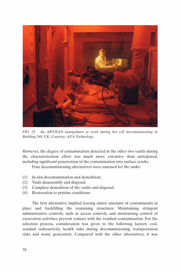
However, the degree of contamination detected in the other two vaults during the characterization effort was much more extensive than anticipated, including significant penetration of the contamination into surface cracks.
Four decommissioning alternatives were assessed for the tanks:
(1) In situ decontamination and demolition;(2) Vault disassembly and disposal;(3) Complete demolition of the vaults and disposal; (4) Restoration to pristine conditions.
The first alternative implied leaving minor amounts of contaminants in place and backfilling the remaining structures. Maintaining stringent administrative controls, such as access controls, and maintaining control of excavation activities prevent contact with the residual contamination. For the selection process, consideration was given to the following factors: cost, residual radioactivity, health risks during decommissioning, transportation risks and waste generation. Compared with the other alternatives, it was
FIG. 25. An ARTISAN manipulator at work during hot cell decommissioning in Building 540, UK. Courtesy: AEA Technology.
78

demonstrated that alternative (1) could be implemented with less risk to workers, a much lower quantity of wastes and substantial cost savings. In addition, a radiological risk assessment for the industrial worker and hypothetical intruder scenarios showed that the additional risks from alternative (1) were trivial, and the decommissioning was completed according to this strategy [189].
The waste calcining facility (WCF) operated between 1963 and 1981. This calcining process converts a liquid waste form into a dry granular solid powder
FIG. 26. Graphite vaults at Vandellós 1 after decontamination and clearance, Spain.
79

form for easier treatment and disposal. In 1998, INEEL, Idaho, initiated a three phase process to close the WCF. The first phase involved filling three basement levels (including rooms, hallways, pipes and vessels) with more than 4200 cubic yards (3200 m³) of grout, creating an underground monolith that encapsulates and prevents migration of any contaminants. The second phase used heavy equipment to demolish the facility. Finally, INEEL grouted the rubble and covered the entire facility site with a clay/earthen protective cap. This is the first time this closure technique has been used at INEEL. According to INEEL, this in situ closure technique offers several advantages over a traditional decommissioning and dismantling project. While reducing exposure to workers and the environment, contaminated wastes are also reduced by 94%, and cost is reduced by 93% [190]. The ability of the national authorities to maintain a definite institutional control period is important for the possibility of implementing such an approach for decommissioning of facilities of this type.
7. CONCLUSIONS AND RECOMMENDATIONS
Decommissioning of underground SSCs can be a major issue in the decommissioning of a nuclear facility and the restoration of its site. Decommissioning of underground SSCs presents a variety of challenges that are sometimes different from those encountered in the decommissioning of conventional above ground facilities:
— Development of a decommissioning strategy;— Lack of information concerning the exact location of underground and
embedded items, their specific features and functions;— Trade-offs between decontamination, fixing contamination or taking no
action prior to demolition and removal;— Radiological and chemical hazards;— Management of any remaining operational wastes;— Dismantling and removal of the underground and embedded items.
In general, proven traditional techniques (for example, excavating and removing items from the top downwards or decontaminating materials at a separate location) are preferable and readily available. In many cases it is possible to make savings by adapting available tools or tools used for non-nuclear purposes. One recurrent problem is that of carefully evaluating at what
80

point a new technique has reached a sufficient degree of maturity to be used with substantial benefits for the project in terms of minimization of project risks, worker exposure, wastes, impact on schedule, and costs.
A review and evaluation of the projects describing decommissioning of the underground components reported in this publication provide recommendations that the reader be encouraged to keep in mind:
(a) At the design stage, selection of the most suitable material of fabrication for the underground and/or embedded components is important. This avoids, in many cases, eventual leakage due to corrosion or perhaps the fact that insufficient surveillance has been carried out. In general, the design of the layout of the underground components of new facilities requires special attention to prevent future problems.
(b) During the facility’s operation, record keeping regarding the underground and/or embedded parts, for example of their location and configuration, is an essential element. This minimizes incidents of inadvertent destruction of pipes or other buried components and prevents a soil contamination problem.
(c) A comprehensive characterization programme of the underground contamination including soil sampling and, therefore, accurate estimates of the quantities of waste materials from the decommissioning work is vital to successful planning for decommissioning of underground SSCs.
(d) Prior to and during decommissioning of underground SSCs, assuring that the utility services are deactivated is an essential safety measure. Other non-radiological hazards, for example toxic materials or working in cramped spaces, are often of concern in underground activities.
(e) Integration of lessons learned from completed projects into future planning for projects of this type in order not to ‘reinvent the wheel’.
Differences among national requirements will affect the decommissioning strategy for underground SSCs; for example, some options, such as entombment, are not allowed in some countries. In turn, such differences will result in a variety of strategies for site closure or release.
81

REFERENCES
[1] INTERNATIONAL ATOMIC ENERGY AGENCY, State of the Art Technology for Decontamination and Dismantling of Nuclear Facilities, Technical Reports Series No. 395, IAEA, Vienna (1999).
[2] UNITED STATES DEPARTMENT OF ENERGY, Decommissioning Handbook, Rep. DOE/EM-0142P, USDOE, Washington, DC (1994).
[3] AMERICAN NUCLEAR SOCIETY, The Decommissioning Handbook, ANS, La Grange Park, IL (2004).
[4] EUROPEAN COMMISSION, Handbook on Decommissioning of Nuclear Installations, Rep. EUR 16211, Office for Official Publications of the European Communities, Luxembourg (1995).
[5] OECD NUCLEAR ENERGY AGENCY, Decontamination Techniques Used in Decommissioning Activities, OECD/NEA, Paris (1999).
[6] WALKDEN, P., TAYLOR, D., Reactor decommissioning in a deregulated market, Nucl. Energy 41 3 (2002) 219–222.
[7] INTERNATIONAL ATOMIC ENERGY AGENCY, Decommissioning Techniques for Research Reactors, IAEA-TECDOC-1273, IAEA, Vienna (2002).
[8] INTERNATIONAL ATOMIC ENERGY AGENCY, Methods for Reducing Occupational Exposures During the Decommissioning of Nuclear Facilities, Technical Reports Series No. 278, IAEA, Vienna (1987).
[9] INTERNATIONAL ATOMIC ENERGY AGENCY, Safe Enclosure of Shut Down Nuclear Installations, Technical Reports Series No. 375, IAEA, Vienna (1995).
[10] INTERNATIONAL ATOMIC ENERGY AGENCY, Design and Construction of Nuclear Power Plants to Facilitate Decommissioning, Technical Reports Series No. 382, IAEA, Vienna (1997).
[11] INTERNATIONAL ATOMIC ENERGY AGENCY, Radiological Characterization of Shut Down Nuclear Reactors for Decommissioning Purposes, Technical Reports Series No. 389, IAEA, Vienna (1998).
[12] INTERNATIONAL ATOMIC ENERGY AGENCY, Decommissioning of Research Reactors: Evolution, State of the Art, Open Issues, Technical Reports Series No. 446, IAEA, Vienna (in press).
[13] INTERNATIONAL ATOMIC ENERGY AGENCY, Decommissioning of Nuclear Facilities Other than Reactors, Technical Reports Series No. 386, IAEA, Vienna (1998).
[14] INTERNATIONAL ATOMIC ENERGY AGENCY, Decommissioning of Contaminated Stacks at Nuclear Facilities, Technical Reports Series No. 440, IAEA, Vienna (2005).
[15] CHARTERS, G., AGGARWAL, S., GILL, J., “Mound plant SW-17 & SW-19 old cave facilities advanced TRUPRO® subsurface sampling”, Waste Management ’05 (Proc. Conf. Tucson, 2005), Waste Management Symposia, Inc., Tucson, AZ (2005) CD-ROM.
82

[16] UNITED STATES DEPARTMENT OF ENERGY, Radioactive Tank Waste Remediation Focus Area: Technology Summary, Rep. DOE/EM-0255, USDOE, Washington, DC (1995)2.
[17] LANGTON, C.A., SPENCE, R.D., BARTON, J., State of the Art on High-Level Waste Tank Closure, Rep. WSRC-TR-2001-00359, Westinghouse Savannah River Company, Aiken, SC (2001).
[18] INTERNATIONAL ATOMIC ENERGY AGENCY, The Decommissioning of WWER Type Nuclear Power Plants, IAEA-TECDOC-1133, IAEA, Vienna (2000).
[19] WALL, S., SHAW, I., “Retrieval of intermediate-level waste at Trawsfynydd nuclear power station”, Nuclear Decom 2001 (Proc. Int. Conf. London, 2001), Professional Engineering Publishing Ltd, London (2001) 255–264.
[20] SMITH, P.K.J., PECKITT, R.A., SALMON, N.P., “Decommissioning the Berkeley vaults — Remote operations”, ibid., pp. 277–286.
[21] ESPALLARDO, J.A., WATSON, C.J.H., Radwaste Vault Clearance at Vandellós IReactor (Spain), Nuclear Decommissioning 1995 (Proc. Int. Conf. London, 1995), Professional Engineering Publishing Ltd, London (1995) 237–244.
[22] SUSANNA, A., ROLLO, C., GAROFALO, A., “Garigliano nuclear power plant — GARITTA and GECO projects — Waste extraction and conditioning”, paper presented at 1st Eur. ALARA Network Workshop on ALARA and Decommissioning, Saclay, 1997.
[23] INTERNATIONAL ATOMIC ENERGY AGENCY, Decommissioning of Nuclear Power Plants and Research Reactors, Safety Guide No. WS-G-2.1, IAEA, Vienna (1999).
[24] UNITED STATES ARMY CORPS OF ENGINEERS, General Design Criteria to Facilitate the Decommissioning of Nuclear Facilities, Technical Manual No. 5-801-10, USACE, Washington, DC (1992).
[25] EBY, R.S., et al., “Research reactor decommissioning planning — It is never too early to start”, International Group on Research Reactors (Proc. 9th Mtg Sidney, 2003), Australian Nuclear Science and Technology Organisation, Lucas Heights (2003), http://www-igorr.cea.fr/proceedings/igorr9/
[26] INTERNATIONAL ATOMIC ENERGY AGENCY, Redevelopment of Nuclear Facilities after Decommissioning, Technical Reports Series No. 444, IAEA, Vienna (in press).
[27] ARGONNE NATIONAL LABORATORY, RESRAD: Family of Risk Codes, http://www.ead.anl.gov/project/dsp_topicdetail.cfm?topicid=21
[28] UNITED STATES DEPARTMENT OF ENERGY, RESRAD-Build: A Model to Estimate Dose from Contaminated Structures, Rep. DOE/EM-0417, USDOE, Washington, DC (1998).
2 For USDOE references identified by DOE/EM-number (Innovative Technolo-gies Summary Reports) check also the web site http://apps.em.doe.gov/ost/itsrall.html, where the reports can be downloaded.
83

[29] DUDA, J., KASPER, K.M., “Innovative technology performance — Demonstrations at Hanford’s C-Reactor facility”, SPECTRUM ’98 (Proc. Int. Conf. Denver, 1998), American Nuclear Society, La Grange Park, IL (1998) 245–250.
[30] INTERNATIONAL ATOMIC ENERGY AGENCY, Application of Radiation Protection Principles to the Cleanup of Contaminated Areas — Interim Report for Comment, IAEA-TECDOC-987, IAEA, Vienna (1997).
[31] INTERNATIONAL ATOMIC ENERGY AGENCY, Near Surface Disposal of Radioactive Waste, IAEA Safety Standards Series No. WS-R-1, IAEA, Vienna (1999).
[32] INTERNATIONAL ATOMIC ENERGY AGENCY, Siting of Near Surface Disposal Facilities, IAEA Safety Standards Series No. 111-G-3.1, IAEA, Vienna (1994).
[33] INTERNATIONAL ATOMIC ENERGY AGENCY, Safety Assessment for Near Surface Disposal of Radioactive Waste, IAEA Safety Standards Series No. WS-G-1.1, IAEA, Vienna (1999).
[34] INTERNATIONAL ATOMIC ENERGY AGENCY, On-site Disposal as a Decommissioning Strategy, IAEA-TECDOC-1124, IAEA, Vienna (1999).
[35] INTERNATIONAL ATOMIC ENERGY AGENCY, Record Keeping for the Decommissioning of Nuclear Facilities: Guidelines and Experience, Technical Reports Series No. 411, IAEA, Vienna (2002).
[36] INTERNATIONAL ATOMIC ENERGY AGENCY, Organization and Management for Decommissioning of Large Nuclear Facilities, Technical Reports Series No. 399, IAEA, Vienna (2000).
[37] OSS, G.E., “Considering public opinion during risk analysis: Don’t incite the bull”, Decommissioning, Decontamination and Reutilization of Commercial and Government Facilities (Proc. Top. Mtg Knoxville, 1997), American Nuclear Society, La Grange Park, IL (1999) 540–546.
[38] INTERNATIONAL ATOMIC ENERGY AGENCY, Configuration Management in Nuclear Power Plants, IAEA-TECDOC-1335, IAEA, Vienna (2003).
[39] STURTEVANT, W.C., et al., “Remote dismantlement by novel adaptations of conventional equipment”, Waste Management ’93 (Proc. Conf. Tucson, 1993), Vol. 2, Waste Management Symposia, Inc., Tucson, AZ (1993) 1505–1510.
[40] UNITED STATES DEPARTMENT OF ENERGY, UNITED STATES ENVIRONMENTAL PROTECTION AGENCY, Preferred Alternative Matrices for Decommissioning, Rev. 2, 30 June 1997, USDOE/USEPA, Washington, DC (1997).
[41] UNITED STATES DEPARTMENT OF ENERGY OFFICE OF SCIENCE AND TECHNOLOGY — TECHNICAL ASSISTANCE TO THE OHIO FIELD OFFICE, Characterization of Underground Piping Contaminated with Radionuclides at the Miamisburg, Columbus, and Ashtabula Closure Projects, USDOE, Washington, DC (2002).
84

[42] UNITED STATES DEPARTMENT OF ENERGY, A Review of Electrical Intrusion Events at the Department of Energy: 2000–2001, USDOE, Washington, DC (2002).
[43] UNITED STATES DEPARTMENT OF ENERGY, Lessons Learned Database, Electrical Intrusion Events, http://www.eh.doe.gov/DOEll/index.esp (available on subscription).
[44] UNITED STATES DEPARTMENT OF ENERGY, C Reactor Interim Safe Storage Communications Plan, http://www.bhi-erc.com/projects/decom/CReactor/docs/COMPLAN.pdf
[45] TURNER, J.R., The Handbook of Project-Based Management, McGraw-Hill, New York (1998).
[46] MANTEL, S.J., MEREDITH, J.R., SHAFER, S., SUTTON, M., Project Management in Practice, Wiley, New York (2003).
[47] KERZNER, H., Project Management: A Systems Approach to Planning, Scheduling, and Controlling, 8th edn, Wiley, New York (2003).
[48] NUCLEAR ENGINEERING INTERNATIONAL, On from the database, Nucl. Eng. Int. (Feb. 2004) 38.
[49] OECD NUCLEAR ENERGY AGENCY, INTERNATIONAL ATOMIC ENERGY AGENCY, EUROPEAN COMMISSION, Nuclear Decommissioning, A Proposed Standardized List of Items for Costing Purposes, OECD/NEA, Paris (1999).
[50] LOUGH, W.T., JOHNSON, W.R., WHITE, K.P., “A multi-criteria decision aid for evaluating nuclear power plant decommissioning”, Decommissioning Symposium (Proc. Int. Symp. Pittsburgh, 1987), Vol. 1, United States Department of Energy, Washington, DC (1987) II-315–II-323.
[51] RAHMAN, A., Multi-attribute utility analysis — A major decision aid technique, Nucl. Energy 42 2 (2003) 87–93.
[52] FLUOR HANFORD, Tank 241-Z-361 Sludge Retrieval and Treatment Alternatives, Rep. HNF-6354, Rev.0, Fluor Hanford, Richland, WA (2000).
[53] BAYLISS, C., LANGLEY, K., Nuclear Decommissioning, Waste Management, and Environmental Site Remediation, Elsevier, Amsterdam and New York (2003) Sect. 7.4.
[54] BURKE, S.P., SMITH, D.I., “Green field decommissioning of an alpha facility”, Nuclear Decommissioning ’98 (Proc. Int. Conf. London, 1998), Professional Engineering Ltd, London (1998).
[55] MORECOMBE, D.J., MUIR, A.S., “Pharmaceutical R&D sites: Radioactive decontamination and decommissioning from a non-nuclear sector perspective”, Radiation Protection (Proc. 11th Int. Congr. Madrid, 2004), International Radiation Protection Association, Washington, DC (2004).
[56] UNITED STATES DEPARTMENT OF ENERGY, Decontamination and Decommissioning Focus Area Technology Summary, Rep. DOE/EM-0253, USDOE, Washington, DC (1995).
85
[57] BOSSART, S.J., HYDE, J.M., VAGNETTI, R.W., “Bringing innovative technologies to the D&D marketplace”, SPECTRUM ’98 (Proc. Int. Conf. Denver, 1998), American Nuclear Society, La Grange Park, IL (1998) 81–87.
[58] KESSINGER, M.K., GREENWALD, W.L., HUFF, F.E., “Cost results and lessons learned from large scale demonstration projects”, ibid., pp. 9–15.
[59] SWEDISH NUCLEAR FUEL AND WASTE MANAGEMENT COMPANY, Paldiski Conceptual Decommissioning Plan, SKB, Stockholm (1995).
[60] UNITED STATES DEPARTMENT OF ENERGY, Report on Baseline Evaluation and Site Familiarization Visit to the Paldiski Naval Reactor Training Facility (1995); copies available from AS ALARA Ltd, Tallinn, Estonia.
[61] PUTNIK, H., AS ALARA Ltd., Tallinn, Estonia, personal communication, 2002.[62] BOWSER, R., et al., Independent Technical Review of the Paldiski Site —
Report on US Mission, 4–5 May 1995; copies available from AS ALARA Ltd, Tallinn, Estonia.
[63] INTERNATIONAL ATOMIC ENERGY AGENCY, Characterization of Radioactively Contaminated Sites for Remediation Purposes, IAEA-TECDOC-1017, IAEA, Vienna (1998).
[64] UNITED STATES DEPARTMENT OF ENERGY, Tomographic Site Characterization Using CPT, ERT, and GPR, Rep. DOE/EM-0517, Washington, DC (2000).
[65] SUB SURFACE SURVEYS, Solana Beach, CA, www.subsurfacesurveys.com[66] FINCI, A.G., et al., “Site or facility characterization using electromagnetic
radiography (EMR)™”, Decontamination, Decommissioning and Reutilization of Commercial and Government Facilities (Proc. 2nd Top. Mtg Knoxville, 1999), American Nuclear Society, La Grange Park, IL (1999).
[67] UNIVERSITY OF DENVER, What is GPR?, Univ. of Denver, CO, www.du.edu/~lconyer/what_is_gpr.htm
[68] APRIL, J.G., et al., “Ground penetrating holography technology demonstration at the 618-4 burial ground, 300-FF-1 operable unit, Hanford site, Washington”, Waste Management ’98 (Proc. Conf. Tucson, 1998), Waste Management Symposia, Inc., Tucson, AZ (1998).
[69] VALENTI, M., “Looking up and looking down”, Mech. Eng. Power (Jun. 2001), http://www.memagazine.org/supparch/mepower01/index.html
[70] OLHOEFT, G.R., Ground Penetrating Radar, GRORADARTM, Golden, CO,http://www.g-p-r.com/
[71] FINCI, A.G., STANFILL, D.F., Electromagnetic radiography (EMR) for the detection of low-level chemical contamination in the ground, Proc. SPIE – Int. Soc. Opt. Eng. 3853 (1999) 49–59.
[72] IDAHO NATIONAL ENGINEERING AND ENVIRONMENTAL LABORATORY, Large Scale Demonstration and Deployment Project, INEEL, Idaho Falls, ID.
[73] UNITED STATES DEPARTMENT OF ENERGY, Wireline Cone Penetrometer System for Multiple Tool Usage, Rep. DOE/EM-0617, USDOE, Washington, DC (2001).
86
[74] UNITED STATES DEPARTMENT OF ENERGY, Cone Penetrometer, Rep. DOE/EM-0309, USDOE, Washington, DC (1996).
[75] UNITED STATES DEPARTMENT OF ENERGY, Fiber Optic/Cone Penetrometer System for Subsurface Heavy Metals Detection, Rep. DOE/EM-0508, USDOE, Washington, DC (2000).
[76] UNITED STATES DEPARTMENT OF ENERGY, Electrical Resistance Tomography for Subsurface Imaging, Rep. DOE/EM-0538, USDOE, Washington, DC (2000).
[77] NDT RESOURCE CENTER, www.ndt-ed.org/index_flash.htm[78] THE E-JOURNAL OF NONDESTRUCTIVE TESTING, www.ndt.net[79] INTERNATIONAL ATOMIC ENERGY AGENCY, Training Guidelines in
Non-Destructive Testing Techniques, 2002 Edition, IAEA-TECDOC-628/Rev. 1, IAEA, Vienna (2002).
[80] INTERNATIONAL GROUP ELVIA, Prague, www.elvia.cz[81] SOULABAILLE, Y., “Cleaning head for decontaminating ducts”,
Decommissioning Challenges: An Industrial Reality? (Proc. Int. Conf. Avignon, 2003), Société Française d’Énergie Nucléaire, Paris (2003) CD-ROM.
[82] INTERNATIONAL ATOMIC ENERGY AGENCY, Guidebook on Non-Destructive Testing of Concrete Structures, Training Course Series No. 17, IAEA, Vienna (2002).
[83] GENERAL ATOMICS, Hot Cell Facility Decommissioning Project — Final Report, Rep. PC-000499/0, General Atomics, San Diego, CA (2001).
[84] BOSSART, S.J., KASPER, K.M., Cutting Edge Characterization Technologies for D&D, Radwaste Mag. (January–February 1999) 23–30.
[85] SMITH, A.M., MATTHERN, G.E., MESERVEY, R.H., Interim Status of the Accelerated Site Technology Deployment Integrated Decontamination and Decommissioning Project, Rep. INEEL/EXT-98-01107, Idaho Natl Engineering and Environmental Lab., Idaho Falls, ID (1998).
[86] BHATTACHARYYA, S.K., et al., “Large scale demonstration of D&D technologies”, Nuclear Engineering (Proc. 5th Int. Conf. Nice, 1997), American Society of Mechanical Engineers, New York (1997).
[87] KENDRICK, D.T., CREMER, C.D., “Pipe ExplorerTM: Overview, applications, and recent developments”, SPECTRUM ’96 (Proc. Int. Top. Mtg Seattle, 1996), American Nuclear Society, La Grange Park, IL (1996) 1038–1045.
[88] UNITED STATES DEPARTMENT OF ENERGY, Pipe Explorer™ Surveying System, Rep. DOE-EM-0440, USDOE, Washington, DC (1999).
[89] UNITED STATES DEPARTMENT OF ENERGY, Technical Basis for Radiological Release of Grand Junction Office Building 2, Vol. 1, Rep. GJO-97-12-FOS, USDOE, Washington, DC (1997).
[90] UNITED STATES DEPARTMENT OF ENERGY, ibid., Vol. 2, Rep. GJO-GJ-45.
[91] CREMER, C.D., Science and Engineering Associates, Inc., Santa Fe, NM, personal communication, 2002.
87
[92] UNITED STATES DEPARTMENT OF ENERGY, Pipe Crawler® Internal Piping Characterization System, Rep. DOE/EM-0355, USDOE, Washington, DC (1998).
[93] FOGLE, R.F., KUELSKE, K., KELLNER, R.A., The visual and radiological inspection of a pipe line using a tele-operated pipe crawler, Radwaste Mag. (Jul. 1996) 41–49.
[94] WILLIAMS, D.B., “Surveys of embedded piping for Shoreham license termination”, Reactor Operations (Proc. 16th Top. Mtg Long Island, 1993), American Nuclear Society, La Grange Park, IL (1993) 239–245.
[95] UNITED STATES DEPARTMENT OF ENERGY, Pipe Inspection Using the Pipe Crawler, Rep. DOE/EM-0425, USDOE, Washington, DC (1999).
[96] UNITED STATES DEPARTMENT OF ENERGY, Pipe Inspection Using the BTX-II, Rep. DOE/EM-0426, Washington, DC (1999).
[97] HUTTER, A., et al., “Innovative characterization technologies in support of DOE/EM D&D activities”, SPECTRUM ’02 (Proc. Top. Mtg Reno, 2002), American Nuclear Society, La Grange Park, IL (2002).
[98] RAWOOL-SULLIVAN, M.W., Alpha Contamination Monitoring for Decontamination and Decommissioning, Rep. LALP-94-145, Los Alamos Natl Lab., NM (1994).
[99] RAWOOL-SULLIVAN, M.W., et al., Alpha Contamination Assessment for D&D Activities: Monitoring Pipe Interiors, Rep. LA-13063-MS/UC-940, Los Alamos Natl Lab., NM (1996).
[100] MacARTHUR, D., RAWOOL-SULLIVAN, M., DOCKRAY, T., “Monitoring pipes for residual alpha contamination”, SPECTRUM ’96 (Proc. Int. Top. Mtg Seattle, 1996), American Nuclear Society, La Grange Park, IL (1996) 1086–1090.
[101] UNITED STATES DEPARTMENT OF ENERGY, Long Range Alpha Detection for Component Monitoring, Rep. DOE/EM-0497, USDOE, Washington, DC (1999).
[102] DUA, S.K., et al., “Measurement of alpha contamination inside large-bore pipes using electret ion chambers”, Decommissioning, Decontamination and Reutilization of Commercial and Government Facilities (Proc. 2nd Top. Mtg Knoxville, 1999), American Nuclear Society, La Grange Park, IL (1999).
[103] KERR, P.L., et al., “Real-time alpha emitter assay of large volumes”, Waste Management ’97 (Proc. Conf. Tucson, 1997), Waste Management Symposia, Inc., Tucson, AZ (1997).
[104] SCIENCE AND ENGINEERING ASSOCIATES INC., Data Sheet — Alpha Measurements Capability in Pipes and Ducts with the Pipe Explorer System, Science and Engineering Associates, Albuquerque, NM.
[105] ULLIVAN, T., et al., “Smart 3-D characterization of subsurface contamination around the below grade ducts at the Brookhaven Graphite Research Reactor”, Waste Management ’01 (Proc. Conf. Tucson, 2001), Waste Management Symposia, Inc., Tucson, AZ (2001).
[106] SANDIA NATIONAL LABORATORIES, Flow Probe™ Chemical Analyzer, SNL, NM, http://www.cpeo.org/techtree/ttdescript/flopro.htm
88

[107] UNITED STATES DEPARTMENT OF ENERGY, Measuring Fuel Contamination Using High Speed GC and Cone Penetration Techniques, USDOE, Washington, DC (1997), www.earthvision.net/industryprograms/pdfs/sc/31186.pdf
[108] SANDFORD, W., et al., “Decommissioning nuclear piping systems: Selecting the right cutting technique”, SPECTRUM ’98 (Proc. Int. Conf. Denver, 1998), American Nuclear Society, La Grange Park, IL (1998) 154–157.
[109] UNITED STATES DEPARTMENT OF ENERGY, BOA-II: Asbestos Pipe-Insulation Removal Robot System, Rep. DOE/EM-0608, USDOE, Washington, DC (2001).
[110] UNITED STATES DEPARTMENT OF ENERGY, Pipe Cutting and Isolation System, Rep. DOE/EM-0448, USDOE, Washington, DC (1999).
[111] ZOLLINGER, W.T., CARNEY, F., “Pipeline blockage unplugging and locating equipment”, Robotics and Remote Systems (Proc. 10th Int. Conf. Gainesville, 2004), American Nuclear Society, La Grange Park, IL (2004) 80.
[112] STEINER, H., PRIESMEYER, U., “Praktische Anwendung von Zerlege- und Dekontaminationstechniken bei der Stillegung von KRB A” (Practical application of size reduction and decontamination technologies for dismantling of the NPP Gundremmingen Block A), Decommissioning and Dismantling of Nuclear Facilities (Proc. Sem. Hanover, 2004), TÜV-Nord, Hanover (2004).
[113] KNAAK, D., KRAUSE, H., “Erfahrungen beim Aufbau und der Inbetriebsetzung von fernbedienten Zerlegeeinrichtungen” (Experiences gained with assembly and operation of remote size reduction systems), ibid.
[114] UNITED STATES DEPARTMENT OF ENERGY, Preferred Decommissioning Technologies Guide, Draft 4, USDOE, Washington, DC (1996).
[115] UNITED STATES DEPARTMENT OF ENERGY, Decommissioning Handbook: Procedures and Practices for Decommissioning, Rep. DOE/EM-0383, USDOE, Washington, DC (2000).
[116] UNITED STATES DEPARTMENT OF ENERGY, Self-Contained Pipe Cutting Shear, Rep. DOE/EM-0394, USDOE, Washington, DC (1998).
[117] UNITED STATES DEPARTMENT OF ENERGY, High-Speed Clamshell Pipe Cutter, Rep. DOE/EM-0375, USDOE, Washington, DC (1998).
[118] ARGONNE NATIONAL LABORATORY, An Evaluation of Alternative Reactor Vessel Cutting Technologies for the Experimental Boiling Water Reactor at Argonne National Laboratory, Rep. ANL-89/31, Argonne Natl Lab., IL (1989).
[119] IDAHO NATIONAL ENGINEERING LABORATORY, Decommissioning of the MTR-605 Process Water Building at the Idaho National Engineering Laboratory, Rep. EGG-2361, INEL, Idaho Falls, ID (1985).
[120] ARGONNE NATIONAL LABORATORY, Decontamination and Decommissioning of the Argonne National Laboratory East Area Radioactively Contaminated Surplus Facilities — Final Report, Rep. ANL-87-18, Argonne Natl Lab., IL (1987).
89
[121] ARGONNE NATIONAL LABORATORY, Decontamination and Dismantlement of the Building 200/205 Pneumatic Transfer Tube at Argonne National Laboratory — East Project Final Report, Rep. ANL/D&D/98-5, Argonne Natl Lab., IL (1998).
[122] ARGONNE NATIONAL LABORATORY, Decontamination and Decommissioning of the Chicago Pile-5 Reactor at Argonne National Laboratory-East — Project Final Report, Rep. ANL/D&D/00-1, Argonne Natl Lab., IL (2000).
[123] HACKMANN, E.K., Decontamination and decommissioning of small-bore pipe, Trans. Am. Nucl. Soc. 75 (1996) 470–471.
[124] DICKINSON, J.W., POLICASTRO, G.V., “Measurement of surface contamination inside plant system piping: Developments made during decommissioning of the Fort St. Vrain nuclear generating station”, Decommissioning, Decontamination and Reutilization of Commercial and Government Facilities (Proc. Top. Mtg Knoxville, 1997), American Nuclear Society, La Grange Park, IL (1997) 288–295.
[125] SEXTON, R.J., ZACHARY, M., “Decontamination and its role in the Fort St. Vrain decommissioning”, SPECTRUM ’96 (Proc. Int. Top. Mtg Seattle, 1996), American Nuclear Society, La Grange Park, IL (1996) 1815–1820.
[126] CLARK, B.D., RICARDO, J.C., “Trojan nuclear plant embedded pipe remediation project”, Decommissioning, Decontamination and Reutilization of Commercial and Government Facilities (Proc. 2nd Top. Mtg Knoxville, 1999), American Nuclear Society, La Grange Park, IL (1999).
[127] HARRINGTON, J.I., Have pipe cleaning system, will travel, Radwaste Solutions, (Nov.–Dec. 2000) 21–25.
[128] RAMACHANDRAN NARENDRAN, P.E., “Technology used in the cleanup of a difficult-to-remediate facility”, SPECTRUM ’96 (Proc. Int. Top. Mtg Seattle, 1996), American Nuclear Society, La Grange Park, IL (1996) 1974–1976.
[129] OAK RIDGE NATIONAL LABORATORY, The Intermediate Level Waste Transfer Line Decommissioning Project Final Report, Rep. ORNL/TM-8897, ORNL, Oak Ridge, TN (1983).
[130] LAMBERT, J.R., “Waste minimization techniques employed for effective removal of low-level radiological waste disposal tubes”, USACE Environmental and Natural Resource Conference (Proc. Conf. Forth Worth, 2003), United States Army Corps of Engineers, Washington, DC (2003).
[131] HOFFMAN, D.E., et al., “Remediation of a former USAF radioactive material disposal site”, Waste Management ’03 (Proc. Conf. Tucson, 2003), Waste Management Symposia, Inc., Tucson, AZ (2003).
[132] BROOKHAVEN NATIONAL LABORATORY, Action Memorandum: Brookhaven Graphite Research Reactor Below-Ground Duct Primary Liner Removal Action, Rep. BGRR_057, BNL, Upton, NY (2003), www.bnl.gov/bgrr/Docs/LinerActionMemo.pdf
90

[133] BODIN, M.F., SAUBLET, M.J.C., PECH, M.R., “Removal of underground piping decommissioning of buried, radiation-contaminated pipes — Procedure used at the La Hague spent fuel reprocessing plant (France)”, Waste Management ’91 (Proc. Conf. Tucson, 1991), Waste Management Symposia, Inc., Tucson, AZ (1991).
[134] AWE ALDERMASTON, An Alternative to the Pangbourne Pipeline, AWE Aldermaston (2000), http://www.awe.co.uk/Images/pangbourne_pipeline_tcm6-1776.pdf
[135] BNFL begins removing waste pipes from Sellafield to the Irish Sea, Nucleonics Week (21 Aug. 2003) 10–11.
[136] INTERNATIONAL ATOMIC ENERGY AGENCY, Personal Protective Equipment, Practical Radiation Technical Manual No. 5, IAEA, Vienna (2004).
[137] BOSSART, S.J., SHOEMAKER, H.D., KASPER, K.M., “Improved technologies to alleviate worker heat stress”, SPECTRUM ’98 (Proc. Int. Conf. Denver, 1998), American Nuclear Society, La Grange Park, IL (1998) 1159–1164.
[138] PULSFORD, S.K., et al., “Results of the heat stress monitoring system innovative technology demonstrated at Hanford’s C Reactor”, ibid., pp. 178–181.
[139] UNITED STATES DEPARTMENT OF ENERGY, Heat Stress Monitoring System, Rep. DOE/EM-0391, USDOE, Washington, DC (1998).
[140] UNITED STATES DEPARTMENT OF ENERGY, Personal Ice Cooling System (PICS), Rep. DOE/EM-0393, USDOE, Washington, DC (1998).
[141] TRIPP, J., MESERVEY, R.H., PHILLIPS, A.M., Savings D&D $$$, Radwaste Solutions (Nov.–Dec. 2000) 36–41.
[142] UNITED STATES DEPARTMENT OF ENERGY, Advanced Worker Protection System (AWPS), USDOE, Washington, DC (1996).
[143] UNITED STATES DEPARTMENT OF ENERGY, FRHAM-TEXTM Cool Suit, Rep. DOE/EM-0353, USDOE, Washington, DC (1998).
[144] UNITED STATES DEPARTMENT OF ENERGY, NuFab™ Anti-Contamination Suit, Rep. DOE/EM-0354, USDOE, Washington, DC (1998).
[145] UNITED STATES DEPARTMENT OF ENERGY, AEA Fluidic Pulse Jet Mixer, Rep. DOE/EM-0447, USDOE, Washington, DC (1999).
[146] UNITED STATES DEPARTMENT OF ENERGY, Comparative Testing of Pipeline Slurry Monitors, Rep. DOE/EM-0490, USDOE, Washington, DC (1999).
[147] HECKENDORN, F.M., et al., “Viewing systems for large underground storage tanks”, Robotics and Remote Systems (Proc. 7th Top. Mtg Atlanta, 1997), Vol. 2, American Nuclear Society, La Grange Park, IL (1997) 675–681.
[148] BECHTEL HANFORD ERC, Hanford Canyon Disposition Initiative, http://www.bhi-erc.com/projects/s_m/cdi/cdi.htm
[149] KRAVARIK, K., et al., “Advanced CA technologies and remotely controlled manipulators used for the decontamination of the A-1 NPP Jaslovske Bohunice”, Safe Decommissioning for Nuclear Activities (Proc. Int. Conf. Berlin, 2002), IAEA, Vienna (2003) Part II–1, pp. 158–166 (CD-ROM).
91

[150] HENNEBORN, A.C., BORLAND, M.W., “Gamma ray imaging in decontamination and decommissioning”, X-Change ’97 — The Global D&D Marketplace (Proc. Symp. Miami, 1997), Hemispheric Center for Environmental Technology, Miami, FL (1997) 3-195–3-201.
[151] UNITED STATES DEPARTMENT OF ENERGY, GammaCamTM Radiation Imaging System, OST Ref. No. 1840, USDOE, Washington, DC (1998).
[152] UNITED STATES DEPARTMENT OF ENERGY, GammaModeler™ 3-D Gamma-Ray Imaging Technology, Rep. DOE/EM-0593, USDOE, Washington, DC (2001).
[153] UNITED STATES DEPARTMENT OF ENERGY, Gamma-Ray Imaging System, Rep. DOE/EM-0390, USDOE, Washington, DC (1998).
[154] AIL SYSTEMS INC., In-Tank Characterization, AIL Systems Inc., Deer Park, NY (brochure).
[155] UNITED STATES DEPARTMENT OF ENERGY, Gamma-Ray Imaging System (PSC/BNFL RADSCAN 600), Rep. DOE/EM-1973, USDOE, Washington, DC (1998).
[156] HUGHES, K., LIGHTFOOT, J., MOTTERSHEAD, G., “RADSCAN™ 600: Remote gamma ray imaging as the basis for a strategic approach to decommissioning”, Decommissioning, Decontamination and Reutilization of Commercial and Government Facilities (Proc. Top. Mtg Knoxville, 1997), American Nuclear Society, La Grange Park, IL (1997) 307–311.
[157] LE GOALLER, C., COSTES, J.-R., “Onsite nuclear video imaging”, Waste Management ’98 (Proc. Conf. Tucson, 1998), Waste Management Symposia, Inc., Tucson, AZ (1998) CD-ROM.
[158] CANBERRA, CARTOGAM — The Real Time Portable Gamma Ray Imaging System (brochure), CANBERRA, Meriden, CT, http://www.canberra.com
[159] SAISHU, S., et al., “Development of decommissioning technology for nuclear power plants in NUPEC”, International Radiation Protection Association Congress (Proc. 10th Congr. Hiroshima, 2000), IRPA, Washington, DC (2000) CD-ROM.
[160] UNITED STATES DEPARTMENT OF ENERGY, Advanced Waste Retrieval System, Rep. DOE/EM-0607, USDOE, Washington, DC (2001).
[161] CALDWELL, T.B., et al., Closing high-level-waste tanks at the Savannah River site, Radwaste Mag. (Mar. 1998) 19–26.
[162] HOLM, E., SRS applies lessons learned from first HLW tank closing, Nucl. Remed. Weekly 4 39 (26 Sep. 1997) 3–4.
[163] UNITED STATES DEPARTMENT OF ENERGY, SRS applies lessons learned from first HLW tank closing, Nucl. Remed. Weekly 4 39 (1997) 1.
[164] KINGSLEY, R.S., REYNOLDS, W.E., HEFFNER, D.C., Engineering and technology in the deconstruction of nuclear materials production facilities, Radwaste Mag. (Jan. 1996) 25–31.
[165] AMERICAN NUCLEAR SOCIETY, Robotics and Remote Systems (Proc. 7th Top. Mtg Atlanta, 1997), American Nuclear Society, La Grange Park, IL (1997).
92

[166] RADER, P.L., CREECH, P.W., MICHIGAN, R.J., “Decontamination and decommissioning of Building 41”, Decommissioning (Proc. Int. Symp. Pittsburgh, 1987), CONF-871018, Vol. 1, United States Department of Energy, Washington, DC (1987) III-210–III-218.
[167] MICHAL, V., KRAVARIK, K., “Technology development for decommissioning in nuclear power plants research institute, Slovak Republic”, Robotics and Remote Systems (Proc. 9th Int. Top. Mtg Seattle, 2001), American Nuclear Society, La Grange Park, IL (2001).
[168] KRAVARIK, K., et al., “Experience with treatment of low level radioactive liquid waste in Slovak Republic”, Waste Management ’04 (Proc. Conf. Tucson, 2004), Waste Management Symposia, Inc., Tucson, AZ (2004) CD-ROM.
[169] BRITISH NUCLEAR FUELS LTD, The Retrieval and Processing of Irradiated Fuel Element Wastes including Magnox and Graphite at BNFL’s Magnox Power Stations (brochure), BNFL, Daresbury (2003).
[170] NUCLEAR ENERGY, Report on waste retrieval from vaults seminar, April 30 2002, Sellafield, Nucl. Energy 41 6 (2002) 366–368.
[171] WALL, S., SHAW, I., Retrieval of intermediate level waste at Trawsfynydd nuclear power station, Nucl. Energy 41 6 (2002) 391–396.
[172] GAROFALO, A., et al., “GECO project — Garigliano NPP — Waste extraction and conditioning”, Radioactive Waste Management and Environmental Remediation (Proc. 5th Int. Conf. Berlin, 1995), Vol. 2, American Society of Mechanical Engineers, New York (1995) 1671–1676.
[173] SOCIETÀ GESTIONE IMPIANTI NUCLEARI, Garigliano NPP Intermediate Level Waste Retrieval and Conditioning, Rep. ENEL-SGN-GAR-10-DR, SOGIN, Rome (1999).
[174] YAHOO! NEWS, Panel weighs nuclear cleanup law changes, Yahoo (6 May 2004).
[175] UNITED STATES DEPARTMENT OF ENERGY, SRS Tank Closure, Rep. DOE/EM-0449, USDOE, Washington, DC (1999).
[176] SMAIL, T.R., HERB, A.M., HALL, M.C., Stabilization of Underground Solvent Storage Tanks, Rep. WSRC-MS-2002-00571, Rev. 1, Westinghouse Savannah River Co., Aiken, SC (2002).
[177] HEINE, W.F., SPEER, D.R., “Decontamination and decommissioning of a fuel reprocessing pilot plant”, Decommissioning of Major Nuclear Facilities (Proc. Int. Conf. London, 1988), Institution of Mechanical Engineers, London (1988) 139–144.
[178] AMEC, GeoMelt™ Technologies, Richland, WA, www.geomelt.com/technologies[179] Energy officials seek alternate cleanup plan for Tennessee nuclear waste, The
Miami Herald (16 Mar. 2004).[180] PETERSON, L., HEATH, D., STEPHENS, P., “Innovations using ultra-light
cellular grout and high strength, medium density grout for stabilization of irradiated components during decommissioning”, Environmental Remediation and Waste Management (Proc. 9th Int. Conf. Oxford, 2003), American Society of Mechanical Engineers, New York (2003) CD-ROM.
93

[181] IDAHO NATIONAL ENGINEERING LABORATORY, Final Report: Decontamination and Decommissioning of RALA Off-gas Cell and Storage Tank, Rep. WINCO-1036, Westinghouse Idaho Nuclear Company Inc., Idaho Falls (1986).
[182] ENTE NAZIONALE PER L’ENERGIA ELETTRICA, Condizionamento dei Rifiuti Contenuti nella Fossa ad Alta Attività della Centrale del Garigliano (Conditioning of Wastes from the High Activity Pit at Garigliano NPP), Rep. USD-GDG-005, ENEL, Rome (1988).
[183] LAFRATE, P., et al., “Los Alamos National Laboratory phase separator pit decommissioning project”, Decommissioning, Decontamination and Reutilization of Commercial and Government Facilities (Proc. Top. Mtg Knoxville, 1997), American Nuclear Society, La Grange Park, IL (1999) 222–228.
[184] MILLER, K., et al., “Decommissioning the Building A 59 hot cells at Winfrith”, Waste Management ’04 (Proc. Conf. Tucson, 2004), Waste Management Symposia, Inc., Tucson, AZ (2004) CD-ROM.
[185] WESCOTT, J.B., MOOS, L.P., “Mixed and low-level radioactive waste disposal from the Argonne National Laboratory – East Map Tube Facility”, Mixed Waste (Proc. 3rd Biennial Symp. Baltimore, 1995), Cognizant Communication Corporation, New York (1995) 11.5.1–11.5.4.
[186] MOOS, L.P., et al., “Decontamination and dismantling of the Argonne National Laboratory – East Map Tube Facility”, Decommissioning, Decontamination and Environmental Restoration at Contaminated Nuclear Sites (Proc. Top. Symp. Washington, 1994), American Nuclear Society, La Grange Park, IL (1994) 164–170.
[187] LOUGHBOROUGH, D., HAMBLIN, C., ASQUITH, J., “Decommissioning of a hot laboratory and cyclotron complex to green field”, American Nuclear Society Summer Conference (Proc. Conf. New Orleans, 1994), ANS, La Grange Park, IL (1994).
[188] SANTIAGO, J.L., MADRID, F., “The decontamination and decommissioning of the graphite silos at Vandellós I”, Safe Decommissioning for Nuclear Activities (Proc. Int. Conf. Berlin, 2002), IAEA, Vienna (2003) Part II–1, pp. 175–179 (CD-ROM).
[189] MOOS, L., HONG, K.-J., GABEL, A.D., “Cost-effective radiological risk reduction: a remediation case study”, Radwaste Mag. (March 1998) 62–67.
[190] RASCH, D., et al., “Integration of RCRA and CERCLA: A case study of closure and post-closure care and monitoring of the waste calcining facility at the Idaho National Engineering and Environmental Laboratory, Waste Management ’01 (Proc. Conf. Tucson, 2001), Waste Management Symposia, Inc., Tucson, AZ (2001).
94

Annexes I–IX
EXAMPLES OF NATIONAL EXPERIENCE
The examples provided in these annexes are extracts from various decommissioning projects and activities related to underground SSCs. The reasons for the decommissioning activities include shutdown of facilities due to incidents, refurbishment of facilities and judicial decisions, as well as planned decommissioning.
The examples cover situational overviews as well as technical, organizational, planning and execution details. These examples also provide some insight into the different decommissioning projects/activities and, being practical examples, provide useful information on how such projects are dealt with by various Member States. It is expected that the problems encountered in different projects will provide useful information to assist others in preparing for decommissioning activities and in finding useful solutions in line with their own regulations and requirements.
Although each decommissioning project is specific due to site conditions, economic considerations and technological limitations, there are some commonalities in terms of the final objective. The examples cited here are not considered to be exhaustive; however, they certainly provide information on the experiences of a number of countries in addressing the various issues that have arisen and approaches that have been taken in the past. The reader is encouraged to evaluate the applicability of these cases to specific decommissioning projects.1
1 Annexes I–IX reflect the experience and views of the national contributors concerned and are not necessarily endorsed by the IAEA nor intended as specific guidance.
95

.

Annex I
DECOMMISSIONING OF A SECTION OF A DISCHARGE LINEIN BELGIUM
I–1. INTRODUCTION
As a result of a judicial decision, a licensed discharge line for very low level radioactive liquid wastewater to the river Molse Nete in Belgium had to be removed from the gardens of seven properties within a time schedule of one year. The pipeline was constructed in 1956 by the Belgian Nuclear Research Centre (SCK·CEN) and transferred the wastes a distance of about 10 km from the Belgoprocess Site 2 to the river Molse Nete. It is an asbestos cement pipeline with a wall thickness of 13 mm and an inner diameter of 20 cm. Individual pipe sections have a length of about 5 m and are interconnected by sleeves. The section to be removed was situated on average about 1 m (maximum 1.6 m) below ground level. Access was hampered by the various structures (for example summer houses and garages) that had since been built in the area. A new steel discharge pipe was installed to ensure the continuity of the discharge authorization.
I–2. PROJECT PLANNING AND MANAGEMENT
I–2.1. Preparatory activities
After the court decision, Belgoprocess immediately started implementation by:
(a) Defining the adapted bypass line. An epoxy coated steel pipe was selected because it should be easy to decontaminate. Under areas of public road a double walled pipeline (3.5 m deep), including a cathodic protection system and a leak detection system, was selected.
(b) Appointing a negotiator for defining and compensating for the damage to the properties of the residents.
(c) Developing a dismantling technique for the removal of the asbestos cement pipeline.
(d) Preparing and applying for the required licences for the work to be carried out.
97
(e) Characterizing the waste materials. It should be noted that during excavation works in his garden in 2001, a resident caused local damage to the pipeline. Belgoprocess immediately repaired the damaged part, and pieces of the pipeline were taken to a laboratory for analyses. On the inner surface of the discharge line a deposit of low level radioactive sludge was detected, the dominant isotopes being 241Am, 137Cs, 60Co, U and Pu. Additional samples were taken and analysed before dismantling commenced. The same isotope ratios were again found.
(f) Developing a detailed internal project application, a decommissioning assignment, a risk analysis of the work plan, a general safety and health plan, and an ALARA study.
(g) Implementing a mock-up test in order to confirm the dismantling technique.
(h) Training of all operators, giving specific emphasis to the non-radiological aspects of the project such as working with asbestos.
The subtasks are indicated in the flow chart shown as Fig. I–1.Before starting the dismantling works at the 1.8 km section, the following
activities were also completed:
— Constructing and connecting the new steel bypass line;— Clearing trees and bushes in the work area (8 m wide);— Reviewing the groundwater level in the section where the pipeline had to
be removed;— Demolition or dismantling of summer houses, stables, ponds, etc., in the
area above the discharge line.
I–2.2. Dismantling activities
After connecting the bypass line to the remaining part of the discharge line and completing the setting up activities at the site (for example, carrying out a local survey to indicate the pipeline route, removing or adapting local constructions, and installing fences and warning signs), the following activities were performed:
(a) Dewatering the discharge line (Fig. I–2). Water was pumped into a 17 m³ tanker and transported to Belgoprocess. After sampling and analysis the liquid was discharged into the river Molse Nete.
(b) Mechanical and manual excavations. The soil above the discharge line was removed using compact excavation machines (Fig. I–3). Soil around the pipe was cleared with a shovel in order to avoid damage to the pipe.
98

Pre
para
tory
act
iviti
es: c
onst
ruct
ion
of th
e ne
w s
teel
bypa
ss li
ne, c
lear
ing
trees
and
bus
hes
in th
e w
ork
area
, rev
iew
ing
the
grou
ndw
ater
leve
l, de
mol
ition
or
dism
antli
ng o
f sum
mer
hous
es, s
tabl
es, p
onds
, etc
.
Dew
ater
ing
the
disc
harg
e lin
eM
echa
nica
l and
man
ual e
xcav
atio
ns
Visu
al a
ndra
diol
ogic
alin
spec
tion
of th
e pi
peaf
ter c
lean
ing
Moi
sten
ing
the
pipe
with
wat
er o
n th
ebo
ring
and
cutti
ngsu
rface
s
Nex
t pip
e
Put
ting
the
pipe
duc
tsin
to w
oode
n tr
ansp
ort
bins
for t
rans
port
atio
n
Sea
ling
the
pipe
end
san
d br
ushi
ng th
e so
ilfro
m th
e su
rface
of
the
pipe
line
Cut
ting
the
slee
ves
orth
e pi
pelin
e w
ith a
spec
ial c
utte
rfo
r asb
esto
s ce
men
t
Inst
allin
g a
drip
tray
unde
r the
are
a w
here
the
pipe
line
shou
ld b
e cu
t
Intro
duci
ng s
peci
alba
lloon
s in
to th
ebo
reho
les
Bor
ing
hole
s w
ith a
spec
ial a
nd s
low
lytu
rnin
g ta
ppin
g to
ol
Con
trolli
ng th
eco
ntam
inat
ion
leve
l in
the
open
tren
ch b
yth
e he
alth
phy
sics
cont
rol o
pera
tor
Taki
ng s
oil s
ampl
esfo
r rad
iolo
gica
lan
alys
es
Mon
itorin
g th
e so
ilsa
mpl
es w
ith a
gam
ma
spec
trom
eter
in a
loca
l wor
k sh
ed
Clo
sing
the
trenc
h if
no a
ctiv
ity a
bove
natu
ral b
ackg
roun
dw
as d
etec
ted
in th
esa
mpl
es
Res
torin
g th
ega
rden
s to
thei
ror
igin
al c
ondi
tion
Mon
itorin
g th
eco
llect
ive
grou
ndsa
mpl
es in
the
Bel
gopr
oces
sla
bora
tory
Phy
sico
chem
ical
anal
yses
in o
rder
tode
fine
poss
ible
chem
ical
gro
und
cont
amin
atio
n
Tran
spor
t of t
he p
ipe
duct
s in
a li
cens
edtr
ansp
ort c
onta
iner
toB
elgo
proc
ess
Siz
e re
duct
ion
of th
epi
pe d
ucts
in th
eB
elgo
proc
ess
cent
ral
deco
ntam
inat
ion
infra
stru
ctur
e
The
was
te d
rum
s w
illla
ter b
esu
perc
ompa
cted
and
cem
ente
d fo
r fin
alco
nditi
onin
g
FIG
. I–1
. U
nder
grou
nd p
ipel
ine
deco
mm
issi
onin
g in
Bel
gium
: flo
w c
hart
for
dis
man
tling
of
the
1.8
km lo
ng u
nder
grou
nd p
ipe.
Cou
rtes
y:
Bel
gopr
oces
s.
99

FIG. I–2. Underground pipeline decommissioning in Belgium: dewatering of the discharge line. Courtesy: Belgoprocess.
FIG. I–3. Underground pipeline decommissioning in Belgium: removal of soil above the discharge line. Courtesy: Belgoprocess.
100
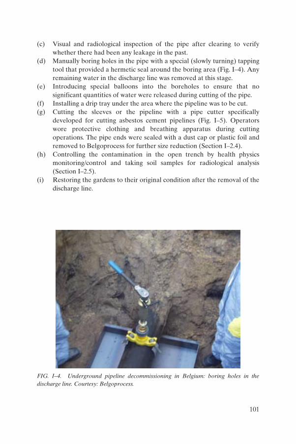
(c) Visual and radiological inspection of the pipe after clearing to verify whether there had been any leakage in the past.
(d) Manually boring holes in the pipe with a special (slowly turning) tapping tool that provided a hermetic seal around the boring area (Fig. I–4). Any remaining water in the discharge line was removed at this stage.
(e) Introducing special balloons into the boreholes to ensure that no significant quantities of water were released during cutting of the pipe.
(f) Installing a drip tray under the area where the pipeline was to be cut.(g) Cutting the sleeves or the pipeline with a pipe cutter specifically
developed for cutting asbestos cement pipelines (Fig. I–5). Operators wore protective clothing and breathing apparatus during cutting operations. The pipe ends were sealed with a dust cap or plastic foil and removed to Belgoprocess for further size reduction (Section I–2.4).
(h) Controlling the contamination in the open trench by health physics monitoring/control and taking soil samples for radiological analysis (Section I–2.5).
(i) Restoring the gardens to their original condition after the removal of the discharge line.
FIG. I–4. Underground pipeline decommissioning in Belgium: boring holes in the discharge line. Courtesy: Belgoprocess.
101

I–2.3. Transport of the pipe ducts
Each individual pipe duct (4 m long) was sealed with a dust cap or plastic foil (Fig. I–6) and placed in a wooden bin (covered with a plastic foil). These wooden bins were then:
— Placed into storage racks;— Loaded into a standard 20 ft (6 m) open top container (IP2 package);— Transported to Belgoprocess by an authorized transport company for
further treatment of the pipe ducts as radioactive wastes.
I–2.4. Treatment of the pipe ducts in the Belgoprocess central decontamination facility
The pipe ducts were transferred for size reduction to the decontamination area, where the plastic foil and the rubber balloons were removed and the remaining liquids collected and removed to the water treatment plant. The rubber balloons were decontaminated for reuse. A rolling belt was installed in the decontamination area in order to speed up and facilitate the size reduction
FIG. I–5. Underground pipeline decommissioning in Belgium: the pipe cutter used for cutting asbestos cement pipelines. Courtesy: Belgoprocess.
102

activities. The pipe ducts were size reduced by means of a cleaving facility (Fig. I–7) in order to obtain maximum filling of the waste drums. These are to be supercompacted and the resulting discs cemented in 400 L drums.
I–2.5. Analysis of the samples
Upon removal of the pipe ducts, soil samples were taken for radiological analysis. These samples were individually monitored with an ISOCS gamma spectrometer, which was installed at a facility in the area. The samples were dispatched to the Belgoprocess laboratory, where they were homogenized and the collective sample radiologically analysed. The results of the analyses were presented to the Belgoprocess health physics control services. In addition to the samples taken by the Belgoprocess health physics control services, soil samples from the area of the discharge line were also taken by an authorized control organization for analysis in an independent laboratory.
In addition to radiological analyses of the soil samples, physicochemical analyses were carried out in order to define possible chemical ground contamination.
FIG. I–6. Underground pipeline decommissioning in Belgium: sealing of the pipe ducts. Courtesy: Belgoprocess.
103

I–3. CONCLUSIONS
The discharge line was safely dismantled and removed; furthermore, it is noted that:
(a) The asbestos cement pipeline (constructed in 1956) was still in a perfect state.
(b) The decommissioning costs were reduced by reuse of materials (rolling belt, transport bins, etc.) and by minimizing the production of secondary wastes.
(c) Time and attention must be spent on communication with residents: many problems were avoided by extensive communications between the negotiator and the residents.
(d) In addition to the radiological aspects of the implementation of the activities, considerable preventive measures were taken in order to reduce the conventional risks (e.g. working with asbestos, working below ground).
(e) The work organization was greatly improved by implementing the mock-up test.
FIG. I–7. Underground pipeline decommissioning in Belgium: size reduction of the pipe ducts. Courtesy: Belgoprocess.
104

(f) The entire project was completed on time, despite the limited time schedule (with a maximum of two months for the complete removal of 1.8 km of pipeline) and the changing weather conditions during the autumn in which the work was done.
105

Annex II
SITUATION OF UNDERGROUND COMPONENTS IN THE NUCLEAR RESEARCH INSTITUTE AT ŘEŽ, CZECH REPUBLIC
II–1. INTRODUCTION
This annex contains some information about components and systems situated in underground areas at the Nuclear Institute Řež (NRI) in the Czech Republic, their operation and their current state. The components are part of the old environmental liabilities.
The NRI remediation projects will consist of work at the following buildings and systems:
— Building 211/5 decay tanks;— Building 211/3 storage tanks;— Building 241, which uses old radioactive waste treatment technology;— Building 250 liquid radioactive waste storage tanks;— A special sewage system;— An Emsher well.
The characterization of environmental liabilities has already been carried out. This work was performed to obtain information about the NRI site, the degree and extent of environmental pollution and the potentially endangered target groups. The first stage comprised the collection of the required information. In the framework of the first stage, a study of the existing data led to the identification of the fact that information was lacking.
A risk analysis study was performed. This comprised the identification and characterization of potential sources of risk, potentially exposed receptors and exposure pathways, potential chemical compounds, radionuclides and media of concern. Additional information on the natural conditions at the site was obtained through hydrogeological studies of the pollution, and information was included in the risk analysis on sources of ionizing radiation and radioactive contamination using dosimetric measurements and radiochemical analyses.
The results of the risk analysis enabled staff to determine the priorities of the remediation project, the technical conception of the remedial actions and an estimate of cost.
106

II–2. BUILDING 211/5 HOUSING DECAY TANKS
Building 211/5 (decay tanks) was designed in 1958 and started to be used in 1961. The building is practically submerged in the terrain on three sides. The building consists of two separate concrete bunkers located partially below ground with a masonry structure above the bunkers. The walls of the bunker are 1 m thick. Each bunker houses a cylindrical tank (length 9.5 m, diameter 3 m and weight approximately 10 t) with a capacity of 63 m3, called a decay tank. The decaytanks are made from structural steel jacketed by stainless steel inside the vessel. One tank serves for storage and the other as a reserve. The design life of these tanks (25 years) has now been reached. The building serves as a store for storage and decay of concentrated short lived radioactive wastes; however, radioactive wastes containing long lived radionuclides have also been shipped there. All transfer of radioactive wastes was stopped in 1990. The masonry building contains tank inlet pipes, ventilation equipment and equipment for taking water samples from tanks. A drawing of building 211/5 is shown in Fig. II–1.
FIG. II–1. Plan of building 211/5 at NRI in the Czech Republic (dimensions in millimetres).
107

The tanks are equipped with two openings, which served for waste receipt and for collection of water samples. A drawing of the decay tank is shown in Fig. II–2.
Tank A contains 4.5 m3 of liquid with an activity of 0.5 MBq/L. The main identified radioisotopes are 137Cs and 152Eu.
Tank B contains 2.5 m3 of solid radioactive wastes and 8 m3 of liquid radioactive wastes with an activity of 21 MBq/L. The main identified radioisotopes are 60Co and 137Cs. However, there is anecdotal evidence that up to 2 g of 239Pu may also have been deposited in the tank.
The solid wastes consist of tins containing irradiated sample residues of irradiated measuring probes, as well as probes used in impact and stretching tests from the reactor vessels, in addition to tins containing fission material from spent fuel (Fig. II–3).
According to measurements made inside tank B, the maximum dose rate of approximately 2 Gy/h is measured at a distance of 10 cm above the pile of solid radioactive wastes. The surrounding bunker contains 2 m3 of water with an activity of less than 20 Bq/L.
Leakage and spillage from the storage tanks and direct irradiation from in situ material were identified as the main risks to the environment and/or to employees.
Inlet tube Inlet tube
Pile of solid waste
–330
82009500
ø 30
00± 0
ø150
1350
2°
1256
350
2110
115
h2h1
456
FIG. II–2. Section of a decay tank in building 211/5 (dimensions in millimetres).
108

The remediation procedure will consist of:
(a) Construction of a facility above the storage tanks for accommodation of technology for removal of radioactive wastes and their processing. This will be equipped with hot cells and manipulators.
(b) Removal of radioactive wastes from the tanks and their direct conditioning in the facility.
(c) Demolition of the facility.(d) Removal of the bunker concrete roof, and decontamination and
dismantling of the tanks and the equipment. Processing of radioactive wastes.
(e) Decontamination and demolition of the building and final restoration of the site.
Construction of the facility is at the stage of advance planning, and removal and processing of radioactive wastes is planned to start soon. This will be followed by final decommissioning and restoration of the site.
FIG. II–3. Radioactive waste stored in decay tank B in building 211/5.
109

II–3. BUILDING 211/3 HOUSING LIQUID RADIOACTIVE WASTE STORAGE TANKS
Three steel tanks of the same design as the decay tanks described in Section II–3 are located in concrete bunkers with 1 m thick walls. These tanks served the purpose of receiving liquid radioactive wastes from the LVR-15 research reactor. The tanks are aged beyond their design life. The integrity of the tanks and surrounding bunkers is doubtful. All three tanks contain 137Cs, 60Co and 90Sr.
Leakage or spillage from these tanks was identified as the main environmental risk. A plan (at ground floor level) of the bunkers is shown in Fig. II–4.
The remediation procedure will consist of:
(a) Decontamination and decommissioning of tanks — removal of the concrete roof of the bunker as well as decontamination and dismantling of the tanks and the equipment.
(b) Processing of radioactive wastes.
FIG. II–4. Plan (at ground floor level) of the bunkers in building 211/3 at NRI in the Czech Republic.
110
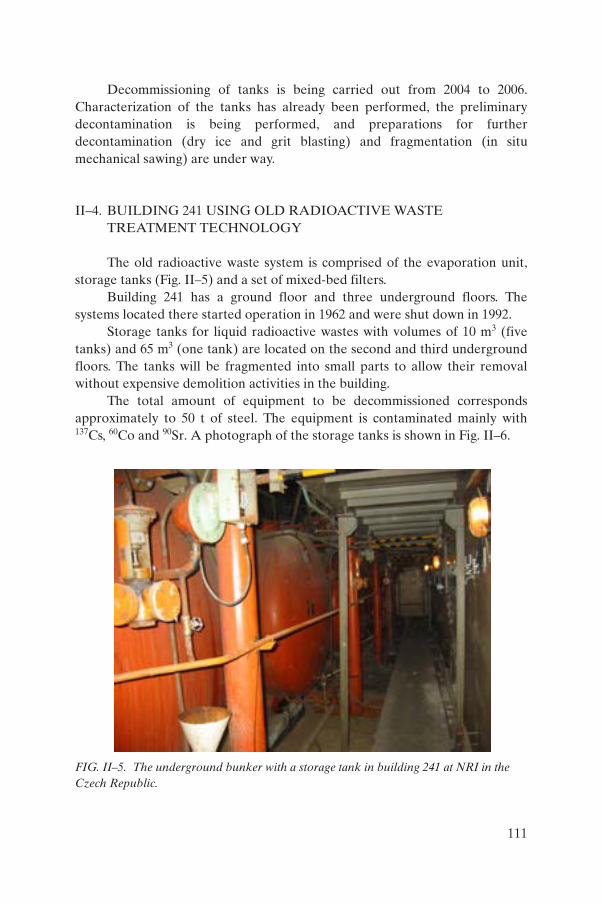
Decommissioning of tanks is being carried out from 2004 to 2006. Characterization of the tanks has already been performed, the preliminary decontamination is being performed, and preparations for further decontamination (dry ice and grit blasting) and fragmentation (in situ mechanical sawing) are under way.
II–4. BUILDING 241 USING OLD RADIOACTIVE WASTE TREATMENT TECHNOLOGY
The old radioactive waste system is comprised of the evaporation unit, storage tanks (Fig. II–5) and a set of mixed-bed filters.
Building 241 has a ground floor and three underground floors. The systems located there started operation in 1962 and were shut down in 1992.
Storage tanks for liquid radioactive wastes with volumes of 10 m3 (five tanks) and 65 m3 (one tank) are located on the second and third underground floors. The tanks will be fragmented into small parts to allow their removal without expensive demolition activities in the building.
The total amount of equipment to be decommissioned corresponds approximately to 50 t of steel. The equipment is contaminated mainly with 137Cs, 60Co and 90Sr. A photograph of the storage tanks is shown in Fig. II–6.
FIG. II–5. The underground bunker with a storage tank in building 241 at NRI in the Czech Republic.
111

The remediation procedure will consist of:
— Dismantling of the equipment after decontamination; — Processing of radioactive wastes.
Decommissioning of these systems is being carried out from 2004 to 2006. Characterization has already been performed, the preliminary decontamination is being performed, and the preparations for further decontamination (dry ice and grit blasting) and fragmentation (in situ mechanical sawing) are under way.
II–5. BUILDING 250 HOUSING LIQUID RADIOACTIVE WASTE STORAGE TANKS
Building 250 houses underground tanks for collection of liquid radioactive wastes. The tanks are placed in the underground bunkers. Decommissioning of tanks will be carried out in 2006 and 2007. Characterization of the tanks has already been performed; the preparation for further decontamination (dry ice and grit blasting) and fragmentation (in situ mechanical sawing) is under way.
FIG. II–6. Storage tanks in building 241 at NRI in the Czech Republic.
112

II–6. SPECIAL SEWAGE SYSTEM
The special sewage system was used for the transfer of liquid radioactive wastes from various facilities (for example, research reactors and radiochemical laboratories) to a radioactive waste processing facility. The system consists of a double walled stainless steel pipe network situated in a steel channel in an underground concrete corridor with a total length of 410 m. The integrity of the system has never been tested. The total amount of contaminated metal parts is approximately 5 t. The concrete corridor was considered to be potentially contaminated. Contamination is mainly caused by 137Cs, 60Co and 90Sr.
Leakage of wastewater from piping was identified as the main risk to the environment.
The remediation procedure comprises of:
— Removal of soil;— Opening of the corridor;— Characterization programme;— Dismantling of pipes;— Processing of wastes.
The decommissioning of the system started in 2004 and will be completed in 2005. A first portion of the system has already been decommissioned. The pipes have been removed and sent for processing. Limited areas of the corridor surfaces were contaminated, probably because of minor leakage in the past. These contaminated surfaces were removed.
II–7. EMSHER WELL
An Emsher well has been used as a septic tank during the construction of NRI. Design drawings indicate a structure with a rectangular underground concrete tank and an inverted pyramidal bottom. The total depth of the well is 8.5 m.
In 1966 the tank was cleaned, the inlet and outlet were sealed with bricks and the tank was subsequently used for storage of solid low level radioactive waste consisting mainly of aluminium boxes contaminated with 125Sb. Documentation relating to permission exists for this storage but gives no details of the characteristics or quantity of wastes that were allowed to be deposited. There are no records of how much, if any, waste remains. Subsequently, the tank was filled with cinders and covered with concrete.
113

It is not known whether any wastes remain in the tank. In addition, the location of the tank is not known precisely. Drilling during the latest site investigation did not encounter deposits, which corresponded with what is understood to be have been involved in the construction of the Emsher well. One borehole log records 3.5 m concrete with no evidence of cinders or wastes beneath; a second log records debris, including old pipework to a depth of 12 m.
BIBLIOGRAPHY TO ANNEX II
PODLAHA, J., “Decommissioning and decontamination and radioactive waste management within the framework of remediation of environmental liabilities in the nuclear research institute Řež plc”, Radioactive Waste Management and Environmental Remediation (Proc. 9th Int. Conf. Oxford, 2003), American Society of Mechanical Engineers, New York (2003) CD-ROM.
114

Annex III
DECOMMISSIONING AT VANDELLÓS 1 NUCLEAR POWER PLANT, SPAIN: EMBEDDED AND UNDERGROUND COMPONENTS
III–1. INTRODUCTION
The Vandellós 1 nuclear power plant (CNV1) is located on the Mediterranean coast in the province of Tarragona in Spain.
The plant is a natural uranium fuelled, graphite gas moderated and cooled type, developed by the UK and France. The design is based on a project originally developed jointly by Électricité de France (EdF) and the Commissariat à l’Énergie Atomique (CEA), which led to the construction of the type A reactors at the Saint Laurent des Eaux nuclear plant site in France (SLA 1 and SLA 2) and at Vandellós. The power output of the plant is 1670 MW(th) and 500 MW(e).
Vandellós entered commercial service in May 1972, and its final shutdown occurred in October 1989, after 17 years of operation with an accumulated energy production of 55 647 GW·h. A turbine fire occurred and precipitated early closure of the plant.
The decommissioning option accepted by the Spanish Ministry of Industry in 1998 consisted of first removing the spent fuel inventory, conditioning the operating radioactive wastes and then undertaking dismantling of almost all the structures and components located outside the reactor vessel. The exception to this dismantling would be for those buildings and structures that ensure confinement of the vessel itself as well as the safety and surveillance of the facility and site. No action will be taken with respect to the vessel in which the defuelled reactor with internal components will remain confined pending completion of the dormancy period.
The project was initiated in November 1992. After six years of basic and detailed engineering, licence procedures, and the preparation of bids and bidding evaluation, the authorization was given in January 1998. Actual work was carried out over five years, from March 1998 to June 2003 (Fig. III–1).
Following the dormancy period, which will last for some 30 years, total dismantling of the remaining installations will be undertaken allowing for complete clearance of the site.
115
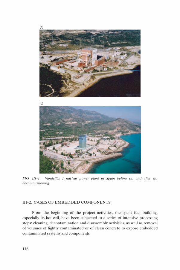
III–2. CASES OF EMBEDDED COMPONENTS
From the beginning of the project activities, the spent fuel building, especially its hot cell, have been subjected to a series of intensive processing steps: cleaning, decontamination and disassembly activities, as well as removal of volumes of lightly contaminated or of clean concrete to expose embedded contaminated systems and components.
(a)
(b)
FIG. III–1. Vandellós 1 nuclear power plant in Spain before (a) and after (b) decommissioning.
116

From the operational period of the building onwards, some embedded components potentially affected by the presence of fixed contamination were sealed and removed. This process was equally applicable to the walls, floor and ceiling of the facility housing the fuel cell, which were removed during the demolition process (Figs III–2 and III–3).
The existence of such elements did not prevent the area from being classified as non-radiological, and their removal in a controlled manner during the process guaranteed the non-existence of remaining uncharacterized or contaminated elements below the filler level and in the demolished concrete.
III–3. DESCRIPTION OF THE PROBLEM
This section includes a brief description of the main structural elements of the nuclear power plant that had some relevance during the dismantling process, in particular, removal of embedded or buried components.
The spent fuel handling building was a metallic structure consisting of inner and outer walls of sheet metal, with a thermal insulating material in-between. The building measured about 36.5 m × 24.0 m, with roofs at three levels at an average height of 13.0 m above the operating floor. The facility housed the following:
(a) A preliminary storage pool, located close to the southern end of the building. It measured 12.0 m × 2.5 m. The total surface area of the pool was 250 m2.
(b) A desleeving pool, located south of the aforementioned pool and to the west. Its approximate dimensions were 3.7 m × 6.2 m. The total surface area of the pool was 154 m2.
(c) A miscellaneous elements storage pool, located south of the aforementioned pool. Its dimensions were 3.7 m × 10.3 m. The total surface area of the pool was 222 m2.
(d) A definitive storage pool, the largest of all the pools, with dimensions of 7.3 m × 17.5 m. The total surface area of the pool was 453 m2.
(e) A washing pool, used for external decontamination (washing) of the casks prior to their exit and on arrival, and measuring 3.85 m × 2.80 m. This pool was not linked to the other pools. The total depth was 3.6 m, with the bottom at elevation +12.50 m. This pool was fitted with an emptying connection measuring approximately 0.6 m × 0.6 m × 0.6 m. The total surface area of the pool was 59.5 m2.
117

(a)
(b)
FIG. III–2. An embedded pipe at Vandellós 1 nuclear power plant before (a) and after (b)removal.
118

These four pools were linked by rectangular penetrations in their bases. Their depth was 7.5 m, from elevation +8.60 m to +16.10 m, 6.5 m of which was lined inside with stainless steel. They all had a draining connection at the bottom, at elevation +8.00 m, measuring approximately 1.1 m × 0.6 m × 0.6 m. All the pools were constructed of concrete with a stainless steel lining. The thickness of the steel liner ranged from 4 to 6 mm.
FIG. III–3. The two ends of the embedded pipe at Vandellós 1 nuclear power plant shown in Fig. III–2 (a).
119

Of special importance in this case was the system for lowering and raising the fuel assemblies. This consisted of a set of devices for lowering fuel assemblies from the fuel building to the preliminary storage pool, and another for hoisting assemblies from the miscellaneous elements storage pool to the irradiated fuel inspection cell. These devices were metallic elements similar to a large diameter tube with lengths of between 10 and 12 m with a chain driven traction system in their interior. They were embedded in the solid concrete walls of the pools.
All the components for communication between the pools and the aforementioned elements constituted a problem, from both the physical and the procedural points of view, for safe extraction without contamination of the concrete in which they were housed.
The irradiated fuel inspection cell was a unique element because of its radiological significance. The cell was a rectangular enclosure made of concrete walls with numerous penetrations in the side walls, floor and roof. Its external dimensions were some 6 m × 6 m in floor area and 4 m in height. The cell was declassified, and all the non-routine components (for example, embedded components) were removed following established procedures.
III–4. SPECIFIC PROCEDURE
Prior to the process of declassification of the different zones of the buildings that are to be demolished in the Vandellós 1 decontamination and decommissioning plan (D&D) plan, the components in the enclosures will have been dismantled and removed in order to leave the areas as clear as possible for the processes of decontamination, characterization and declassification.
The process described above is an ideal one and cannot always be fully accomplished in all the working areas. There are various components, generally mechanical (embedded piping, penetrations, plates, etc.), that cannot be removed without major structural work to the building itself or without affecting its integrity. In the context of declassification, these components are known as singularities (non-routine components, for example embedded components), and their treatment is the subject of the present report.
III–4.1. Operational approach to singularities
All non-routine components, regardless of type, must be identified in the process of characterization of surfaces, and they must also be presented in grid drawings of the surface.
120

Radiological singularities must be confined in order to prevent the spread of radioactive contamination in an area. The sealing of these components must be resistant not only during the declassification process but also during the process of facility demolition.
Radiological singularities must be shielded to the extent that they affect characterization of the surface on which they are located, and they must be visibly labelled in accordance with the requirements of the Vandellós radiation protection handbook.
All singularities, regardless of type, must be listed, together with their data, and they must be included in the declassification dossier for each release unit. There will be a list of singularities per building or structural assembly to be demolished.
III–4.2. Actions subsequent to declassification
The process of declassification of areas containing singularities will be subject to the following measures during the demolition of the building or structural assembly:
(a) Controls should be in place to ensure that all controlled singularities are removed during demolition of the building.
(b) Radiological singularities should not lose their integrity during the demolition process.
(c) Appropriate techniques should be applied to ensure that during operation or disassembly the singularity has not affected the host concrete.
The subprocess of removing singularities within the general process of demolition shall be subject to the applicable requirements of the Vandellós radiation protection handbook, depending on the radiological data that each component has or may produce.
Once removed, both radiological and non-radiological components shall be treated like any other item of equipment included in the decommissioning plan, i.e. they will be characterized and handled as radioactive wastes or materials that can be declassified.
Concrete and rubble from the demolition of an assembly may not be crushed or disposed of irreversibly until such time as the removal of all associated components has been verified.
121
III–5. CONCLUSIONS
The presence of embedded and underground components is a common problem in a number of facility decommissioning projects. In the decommissioning of the Vandellós nuclear power plant this problem was also encountered.
The problem of dismantling, on the one hand, presents technical difficulties in extracting these problematic components and, on the other hand, is further complicated by the precautions that are necessary in order to avoid spread of radiological contaminants.
In facilities where a programme for material and site release has been established, the underground and embedded components present special difficulties, since to release the sites or structures it is necessary to remove these components previously or to demonstrate their compliance with the release criteria.
Specific procedures must be established such that the disturbances caused by the presence of underground and/or embedded components can be solved and a release protocol established for the decommissioning activities to proceed in a timely manner.
122

Annex IV
DECOMMISSIONING AND SITE RESTORATION OF THE SWISS UNDERGROUND EXPERIMENTAL POWER REACTOR AT LUCENS
IV–1. INTRODUCTION
The Swiss Lucens reactor facility was dismantled after an accident at the facility in 1969. Details of the accident can be found in Refs [IV–1–IV–3], and a summary of the dismantling activities is given in Ref. [IV–4]. This annex provides details of the dismantling work, as well as details that have not been published before on the entombment of the underground structures. Thirty years after the accident the decision was made to fill and seal the caverns housing the reactor facility, and to release and terminate its nuclear licence. The site was released from regulatory oversight in 2003 in a condition that allows public access for observation of the conditions at the site. On the completion of this work the decision was made by the Swiss regulatory authorities to permanently terminate research activities here. Actions at the site are considered to be complete.
Owing to the accident about 4.44 TBq (primarily 137Cs and 90Sr) of radioactivity contaminated the reactor systems and the reactor tank. There were no occupational radiation exposures to the staff and no releases to the public — the safety systems as designed operated properly.
However, the subsequent cleanup process forced the operators to strongly reconsider and then make drastic changes to the plans for a replacement of the first core that had been intended earlier. For a better understanding of the subsequent descriptions, the configuration of the caverns in the hill and a cross-section of the reactor cavern are shown in Fig. IV–1.
IV–2. STRATEGY FOR DISMANTLING
The former Swiss Federal Institute for Reactor Research (EIR) with its Hot Laboratory was engaged to assist with determining the cause of the accident. The inquiry commission and the safety authority made suggestions for further dismantling steps within the framework of these investigations.
The following procedures and dismantling steps were not foreseen in the earlier core dismantling study. As a result of the accident, dismantling could be performed only through the use of tools and procedures specially adapted to the situation due to the partially destroyed internal parts. As a consequence,
123
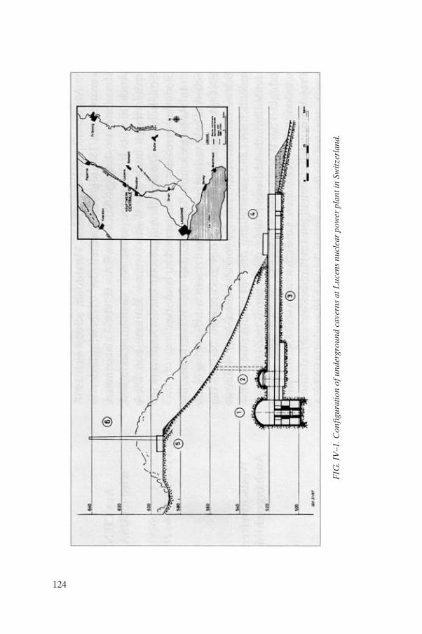
FIG
. IV
–1. C
onfi
gura
tion
of u
nder
grou
nd c
aver
ns a
t Luc
ens
nucl
ear
pow
er p
lant
in S
witz
erla
nd.
124

many of these actions resulted in procurement of custom designed equipment. The dismantling steps additionally required included:
— Recovering and refining the D2O;— Conducting an inspection campaign for identification of the damage;— Constructing a core mock-up to evaluate removal of spent fuel assemblies
(SFAs);— Fractionalizing the CO2 collector and distributor headers;— Repairing the fuel handling machine;— Cutting the moderator tank lid;— Removing SFAs, fractionalizing SFAs in the fuel pool and loading cut
material into transport flasks;— Segmenting calandria tubes;— Dismantling the partially fractionalized moderator tank;— Dismantling the biological shield.
As well as these actions, additional and repetitive measures to perform the required decontamination work and to allow for installation of mobile shielding needed to be performed to enable access to the equipment to be dismantled.
IV–3. DISMANTLING STEPS REQUIRED DUE TO THE ACCIDENT
IV–3.1. Refining of D2O
One of the first measures after the accident was aimed at improving accessibility to the lower part of the reactor cavern to assist in the recovery of the portion of the D2O that had collected in the sump of the reactor cavern. Nearly 90% of the total D2O inventory could be recovered within four days and stored in different vessels and containers according to the different degradation levels. Each category was purified using a different method. One comprised the construction of a battery of filters using pulped material as filter material to effectively decontaminate the D2O. This recovery action took six months, with four or five persons working in fully pressurized plastic suits.
IV–3.2. Construction of a core mock-up and removal of fuel
Following the first inspections of the core after the accident, it was found that the SFAs could not be retracted from the bottom of the core by the fuel replacement machine (FRM) using the normal methods. An endoscope and a
125

TV camera were used, and the crew adapted the latter item with a special swivel and tilting head feature for this work (Fig. IV–2).
This camera was inserted into the fuel channels, with the resulting video information being used to construct a mock-up with the fuel channels, fuel assemblies and pressure tubes on a 1:1 scale representing even the damaged fuel. In addition to the video information, an observation hole for an endoscope was drilled into the lid of the moderator tank by milling (Fig. IV–3). This mock-up was installed in the machine cavern and was utilized for training staff on the use of the various tools and numerous grippers developed on-site for remote interventions inside the calandria tank. Moreover, the crew was trained to remove the fuel assemblies against the normal direction, namely from the head of the core into the FRM. For that purpose the FRM was demounted and remounted on the floor above the reactor pit (Fig. IV–4).
Despite these mock-up trials, some fuel assemblies could only be retracted by use of destructive methods.
FIG. IV–2. The TV camera with custom made swivel and tilt joints used at Lucens.
126

FIG. IV–3. Drilling of an observation hole into the lid of the moderator tank at Lucens.
FIG. IV–4. The provisional docking station on top of the core at Lucens.
127

IV–3.3. Removal of the moderator tank lid
The annulus between the moderator tank and the concrete biological shield, accessible only when the radial steel biological shield was removed,enabled instalment of a tool carrier capable of carrying a sabre saw and a drilling machine. By travelling around the moderator tank, its lid could be separated from the cylindrical shell. The moderator lid could then be lifted through use of an auxiliary hoist.
IV–3.4. Fractionalizing of fuel assemblies
A special medical operating table was procured and mounted onto the bottom of the fuel pool in the pool cavern and supplemented by a fuel bundle shearing tool actuated by means of water instead of hydraulic oil.
This facilitated the size reduction of the SFA into smaller pieces and allowed these to then be inserted into a shielded transportation flask. The fuel was then shipped to the former Belgoprocess reprocessing plant in Mol, Belgium.
IV–3.5. Segmenting of CO2 circuit distributors and collector headers
Partially activated tubes of the primary CO2 cooling loops could not be cut by normal readily available tools, since the material was fabricated from special steel alloys. The solution was found by chance; an in-pipe cutting tool was obtained from an old UK steam cylinder repair shop formerly used for work on railway locomotives. A brittle fracture could be artificially produced using this method in the originally ductile material. All the CO2 pressure tubes could be segmented using this method (Fig. IV–5).
IV–3.6. Dismantling of heat insulation material
The rock wool thermal insulating material on the systems piping was removed using specially fabricated pincers with enlarged branches (Fig. IV–6).
128

FIG. IV–5. The in-pipe cutter used at Lucens for CO2 pressure tubes.
FIG. IV–6. The pincers with prolongation bars used at Lucens.
129
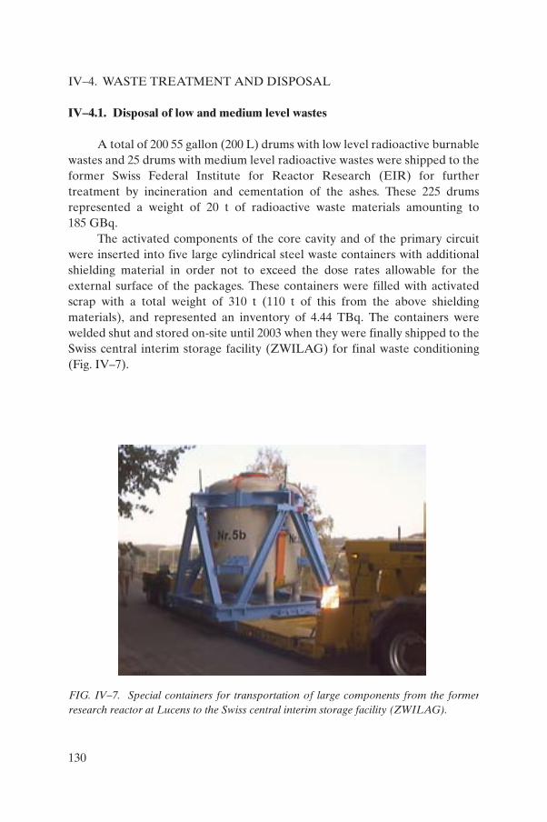
IV–4. WASTE TREATMENT AND DISPOSAL
IV–4.1. Disposal of low and medium level wastes
A total of 200 55 gallon (200 L) drums with low level radioactive burnable wastes and 25 drums with medium level radioactive wastes were shipped to the former Swiss Federal Institute for Reactor Research (EIR) for further treatment by incineration and cementation of the ashes. These 225 drums represented a weight of 20 t of radioactive waste materials amounting to 185 GBq.
The activated components of the core cavity and of the primary circuit were inserted into five large cylindrical steel waste containers with additional shielding material in order not to exceed the dose rates allowable for the external surface of the packages. These containers were filled with activated scrap with a total weight of 310 t (110 t of this from the above shielding materials), and represented an inventory of 4.44 TBq. The containers were welded shut and stored on-site until 2003 when they were finally shipped to the Swiss central interim storage facility (ZWILAG) for final waste conditioning (Fig. IV–7).
FIG. IV–7. Special containers for transportation of large components from the formerresearch reactor at Lucens to the Swiss central interim storage facility (ZWILAG).
130
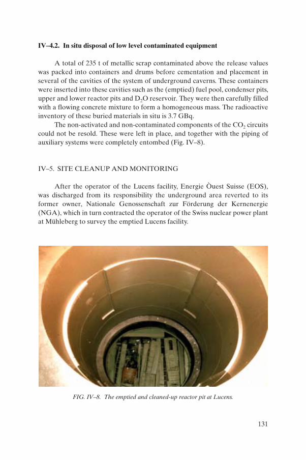
IV–4.2. In situ disposal of low level contaminated equipment
A total of 235 t of metallic scrap contaminated above the release values was packed into containers and drums before cementation and placement in several of the cavities of the system of underground caverns. These containers were inserted into these cavities such as the (emptied) fuel pool, condenser pits, upper and lower reactor pits and D2O reservoir. They were then carefully filled with a flowing concrete mixture to form a homogeneous mass. The radioactive inventory of these buried materials in situ is 3.7 GBq.
The non-activated and non-contaminated components of the CO2 circuits could not be resold. These were left in place, and together with the piping of auxiliary systems were completely entombed (Fig. IV–8).
IV–5. SITE CLEANUP AND MONITORING
After the operator of the Lucens facility, Energie Òuest Suisse (EOS), was discharged from its responsibility the underground area reverted to its former owner, Nationale Genossenschaft zur Förderung der Kernenergie (NGA), which in turn contracted the operator of the Swiss nuclear power plant at Mühleberg to survey the emptied Lucens facility.
FIG. IV–8. The emptied and cleaned-up reactor pit at Lucens.
131

The work programme performed from 1972 to 2003 was not a straightforward strategy for declassification and release of the site from nuclear supervision. On the contrary, it reflected a failed endeavour to reuse the site for nuclear purposes, as well as to develop a proper strategy, with the following elements:
— Storing the five scrap waste containers outside the caverns but on-site for a period of several years;
— Monitoring the groundwater effluents;— Investigating the question of further nuclear reuse of the site (e.g. use for
interim storage of spent fuel and high level vitrified wastes);— Carrying out experimental investigations of the leaching behaviour of the
groundwater in the concrete as well as performing a study on the rise of groundwater levels in the caverns when drainage was stopped.
— Outlining a conceptual design study for refilling the caverns as the basis for an application for site declassification;
— Carrying out detailed engineering work refilling the caverns;— Installing an enhanced drainage system;— Refilling and sealing the caverns with concrete;— Declassifying the site (except for the interim surface store for scrap
containers);— Archiving all relevant documentation;— Transporting the special waste containers to ZWILAG;— Releasing the site from regulatory control.
In a first step the site was released from regulatory control by an official act of the Swiss government in 1995.
Then the Swiss Federal Office for Public Health accepted the responsibility for monitoring the wells and recording the results of their programme for monitoring water quality. In addition, periodic background radiation dose rate measurements of the site are performed via air overflights conducted by the Swiss Office of Surveillance of Radioactivity. The results are published once a year by the Swiss Federal Nuclear Safety Inspectorate (HSK), work that will continue until 2025.
In a second step, the controlled zone for on-site interim storage of the special scrap containers was released after the shipment of the six waste containers to ZWILAG in 2003. The total site area is now declassified. After transfer of the property to the Swiss canton authorities of Vaud, the former machine hall cavern and the access tunnel were transformed into a storage area for cultural and historic exhibits (such as medieval period skeletons), thus creating a virtually unlimited non-nuclear reuse of parts of the site.
132
After the final decision in 1988 not to reuse the site for other nuclear purposes, the application files for site declassification were sent to the Swiss nuclear safety authority HSK.
The safety requirements set by HSK for this case were simple and clear:
— The underground caverns are not a final repository.— The caverns must maintain their stability.— No groundwater should migrate across the caverns.— There should be no residual contamination in the groundwater.
A conceptual design was outlined corresponding to these requirements [IV–5]. The following are the general design aspects selected for these activities:
— None of the scrap waste containers will be entombed in the caverns.— The reactor cavern and the pool cavern will be refilled with concrete for
further structural stability.— A grout mixture will be injected between the cavern lining and refilled
concrete via a system of flexible perforated hoses mounted on the cavern lining before refilling the caverns.
— A drainage system will be installed to prevent the groundwater from exerting a hydraulic force on the concrete lining of the caverns.
The new drainage system and the grout injection system were installed on the basis of this design concept (Figs IV–9 and IV–10), and the reactor and pool caverns were refilled with concrete (Fig. IV–11). This work was completed and the declassification of the underground area was achieved in 1995. The discharge of collected drain waters will be monitored until 2025; the annual readings to date do not indicate any abnormal values [IV–6].
The monitoring system comprised measurement of temperatures of the concrete during the curing period, as well as measurement of the amount of drained water, together with its physical and chemical properties. The installed drainage system is inspected periodically.
Work on the entombment project was completed on time, within budget and with an excellent safety record [IV–7].
133

IV–6. CONCLUSIONS
The Lucens experimental underground reactor was the first Swiss reactor of its kind to undergo the complete decommissioning process through to site declassification and public reuse. The reactor was completely dismantled and the resulting wastes treated according to established waste disposition paths in Switzerland. The caverns in which the reactor was situated were remediated to allow for unlimited access. For its entombment, a safety strategy was established for the facility and the site was remediated and declassified accordingly. Afterwards, the site was transferred to a State owner who is reusing it for storage of cultural and historical artefacts. The remaining wastes were shipped to the Swiss Central Interim Storage and the site was released from nuclear supervision. The effluents from the site will be monitored until 2025.
FIG. IV–9. Installation of a new cavern drainage system at Lucens.
134

FIG. IV–10. Installation of a grouting hose system at Lucens.
135

REFERENCES TO ANNEX IV
[IV–1] SWISS FEDERAL DEPARTMENT OF ENVIRONMENT, ENERGY, TRANSPORT AND COMMUNICATIONS (former EVED), Inquiry Commission for the Safety Related Investigation of an Accident in the Experimental Nuclear Power Reactor at Lucens, Final Report, Federal Printing and Material Center, Berne (1979) (in German).
[IV–2] SWISS NUCLEAR SOCIETY, History of Nuclear Technology in Switzerland, SNS, Berne (1992) (in German).
[IV–3] MOSELY, D., Nuclear Safety and the Role of Institutional Failure, Nuclear Engineering International, Sidcup, UK (1990).
[IV–4] BUCLIN, J.P., “Déclassement de la Centrale Nucléaire Experimentale de Lucens”, Decommissioning of Nuclear Facilities (Proc. Symp. Vienna, 1978), International Atomic Energy Agency, Vienna (1979) 449–476 (in French).
[IV–5] DROZ, P., “Thermal shrinkage of massive concrete: The case of Lucens nuclear power plant”, Creep and Shrinkage of Concrete (Proc. 5th Int. Symp. Barcelona, 1993), RILEM Publications, London (1993) 769–774.
[IV–6] SWISS FEDERAL NUCLEAR SAFETY INSPECTORATE, Annual Report, HSK, Villigen-HSK (2002) 60.
[IV–7] DROZ, P., Stucky SA, Renens, Switzerland (formerly Bonnard and Gardel Consulting Engineers, Lausanne), personal communication, 2004.
FIG. IV–11. Refilling of caverns with concrete at Lucens.
136

Annex V
RECENT EXPERIENCE IN DECOMMISSIONING DRAINS AND UNDERGROUND DUCTS, UK
V–1. INTRODUCTION
The United Kingdom Atomic Energy Authority (UKAEA) is responsible for managing the decommissioning of the nuclear reactors and other radioactive facilities used for the UKAEA nuclear research and development programme with the objective of restoring the sites for conventional use. The UKAEA currently carries out these activities at its sites at Windscale (Cumbria), Harwell (Oxfordshire) and Winfrith (Dorset) in England, and at Dounreay (Caithness) in Scotland.
The management, treatment and final discharge of liquid wastes is carried out in dedicated facilities, which are usually located at the topographically lowest point on the site. The bulk of the contaminated effluents are transferred (by gravity flow) through extensive systems of delay tanks and deep underground drains. Many of these were designed, installed and commissioned up to 50 years ago, at a time when considerations about final decommissioning did not influence designs. Indeed, convenience and the need to rapidly develop sites often drove decisions. As a consequence there are significant differences in the way the drainage systems were installed. For example, some pipes are contained within concrete ducts while others are simply laid in soil; some sections of drain have readily accessible inspection chambers while others do not. These arrangements influence the chosen decommissioning strategy. Other factors that need to be considered include:
(a) Uncertainties associated with the location of system components due to inconsistencies in records (for example, in the as-built specifications, modifications made and operating practices);
(b) The presence of other services (electricity, water, foul sewers, gas and fibre optic cables) which all run in areas adjacent to (or above) the active drains;
(c) The physical integrity of the drains and possible leakage of radioactivity into the surrounding soil;
(d) The possible presence of significant quantities of sludge or deposits within the pipes and/or chambers;
(e) The prevention of groundwater ingress into deep excavations;(f) Waste assay and management in remote areas of the site.
137

The decommissioning of the site drainage systems is underway at both Harwell and Winfrith, where work is proceeding to develop these sites for other uses. The strategies employed on both sites are broadly similar and are discussed below.
V–2. DECOMMISSIONING STRATEGY AND EXPERIENCE ON TRADE WASTE DRAINS AT HARWELL
Trade waste effluents at Harwell are permitted to contain very low levels of radioactivity. The trade waste drainage system includes approximately 15 km of pipes ranging from 0.6 to 0.08 m in diameter, which connect individual buildings to the site effluent treatment plant. Many of these are simply buried in soil 5–6 m below the surface. As operations on the site have been reduced (with concomitant reductions in the volumes of effluents generated), significant parts of the trade waste system have become redundant. Furthermore, some sections of drain have become isolated from the remainder of the system during the demolition of buildings they once served.
Decommissioning of the redundant drains is under way. Considerable efforts have been made to establish the locations of the drains and other components (including searches of records, trial digs, surveys using ground penetrating radar and CCTV surveys). The Harwell trade waste drains are generally glazed ceramic pipes, although some steel pipes were used. The results from initial soil sampling exercises showed no evidence of leakage of radioactivity into areas adjacent to the drains, confirming their continued integrity. Assessments showed the industrial risks associated with excavations at depths of up to 6 m to be considerable (especially given the proximity of sensitive and/or hazardous services). The chosen decommissioning strategy is therefore based upon in situ cleaning and involves ‘minimal’ excavation.
Work has commenced on the trade waste drains furthest from the site effluent treatment plant. Significant sections of abandoned drain have been successfully cleaned using water jets (Fig. V–1). The deposits removed are washed into the inspection chambers, where they are recovered by a suction tanker for immobilization and disposal. The wash-water is recirculated during cleaning. It is finally discharged into an uncleaned section of drain to flow to the effluent treatment plant for processing.
Radiological surveys are conducted after cleaning using a high resolution radiation detector. The original detector (Fig. V–2) was designed to be capable of accessing the drains through the available access points and making gross activity measurements in pipes with a range of diameters. This unit was
138

manually pulled along a section of the drain and possessed somewhat limited data acquisition capacity. Winfrith staff have recently improved the functionality and operability of this unit. The modified unit is self-propelled and can also carry a colour camera unit for visual inspection of the pipes to help identify potential damage (and hence leak paths). Other developments include gamma spectrometry and data logging functions.
The sections of pipe where measurable contamination persists are recleaned and remonitored. If recleaning is unsuccessful then the contaminated pipe is removed by excavation; this has not been necessary to date, however. The cleaned pipes are filled with a concrete based grout, which is pressure injected at the inspection chambers. Selected sections of grouted pipe have been removed to confirm the adequacy of the injection process (Fig. V–3).
Before After
FIG. V–1. Cleaning of a trade waste drain at Harwell, UK, using a water jet system.
FIG. V–2. The pipe survey equipment in use at Harwell, UK.
139

The pressure washing system, the suction tanker and the radiation detector are all based upon available equipment that has been modified or developed for use in the applications described. For example, the wash-head is based on industrial equipment initially developed for cleaning foul sewers and drains. Modifications were made to enable it to continue to remove the silt that had settled in the pipes and also to dislodge the ‘scale’ that had adhered to the trade waste drain walls. Site trials were an essential part of this development process and have helped to reduce risk, cost and timescale.
The sections of drain that are no longer connected to the effluent treatment plant cannot be cleaned in this manner without installing temporary facilities to collect the wash water. The installation of such facilities involves significant design effort and extensive excavation work. As a result, the dead-legs are being removed for disposal. The excavations involved are carefully controlled and monitored. Regular radiological monitoring is carried out and the results from the extensive sampling and analysis of the material surrounding the pipes gives further confidence that large scale leakage has not been an issue in the past.
The inspection and access chambers are temporarily enclosed (within a suitable tent) and are cleaned using standard concrete decontamination techniques (e.g. abrasive scabbling). Wherever possible the contamination monitoring and cleaning equipment is deployed remotely from outside the chamber. Human access is sometimes necessary, but is carefully controlled.
FIG. V–3. Grouted drain section at Harwell, UK.
140

Once the desired end point has been achieved, the top two metres of concrete are removed, crushed and used to help fill the remaining chamber, which is then covered with a concrete cap. Finally, the site records are updated to ensure that what remains is recorded accurately.
V–3. CONCLUDING REMARKS
The following lessons can be learned from the decommissioning of underground pipes in the UK:
(a) The records of site drainage systems are often inadequate. Surveys are essential to establish both the location and the nature of the components and their radiological condition.
(b) The development and/or modification of existing equipment and technology for a particular application can help to reduce the cost and timescale.
(c) Regular radiological monitoring is essential during the excavation of contaminated pipes in order to ensure that conditions have not changed.
V–4. DECOMMISSIONING OF THE BEPO REACTOR AIR COOLING DUCTS
The British Experimental Pile O (BEPO) reactor was constructed on the Harwell site in the mid-1940s. It is housed in Hangar 10 and was finally shut down and defuelled in the late 1960s. BEPO was air cooled, and the cooling air entered and left the reactor through 2.5 m × 3 m ducts, which were about 80 m long and 9 m below the local ground level. Both ducts were lined with up to 600 mm of reinforced concrete. The outlet duct was clad with aluminium plates bolted to the concrete. The outlet air, having passed through a series of filters and monitoring equipment located in the outlet duct, was exhausted to the atmosphere through a 61 m tall stack. Both ducts were sealed shortly after the removal of the fuel by the construction of concrete shield walls at their entrances to the reactor block.
The sealed reactor block is currently under care and maintenance. Decommissioning of the peripheral buildings and facilities (including the air cooling ducts) is complete.
The first stages of removal of the ducts involved upgrading the access arrangements to modern standards and establishing the ‘confined space’ working arrangements. Temporary ventilation systems (fitted with HEPA
141

filters) were installed to ensure adequate air quality and maintain reasonably comfortable working temperatures within the ducts. Equipment was also developed to minimize manual handling within the ducts. Commercially available mobile hoists and pallet trucks were adapted to enable them to be taken into the ducts through the existing human access points. Mobile cranes were also provided for removing the wastes from the ducts (again through the existing access points).
Initial radiological surveys confirmed the existing records:
(a) The air inlet duct was free from contamination.(b) Contamination in the outlet duct was present in localized areas (and was
mainly comprised of 137Cs).(c) The presence of the concrete shield walls ensured that the radiation levels
in both ducts were low (<10 mSv · h–1).
The radiation and contamination levels therefore did not unduly restrict access into the ducts for subsequent decommissioning operations. The surveys also showed that the outlet duct had suffered from the ingress of water and that this had caused some corrosion of the aluminium cladding.
Initial decommissioning operations involved removal of the aluminium cladding (and the corrosion debris), filter housings and monitoring equipment from the outlet duct. The plates were progressively removed from defined areas, working from the reactor end of the duct. Each area was enclosed within a temporary containment to prevent contamination spread (especially to areas where the concrete beneath the plates had been exposed). A dedicated waste processing enclosure was also set up within the duct to ensure that loose contamination was not transferred on to the packages of waste from the duct. Portable mechanical saws and hydraulic shearing tools were used to remove the filter housings as well as the air monitoring and control systems. Temporary containment was again used to prevent spread of contamination.
An extensive programme of radiological surveys followed in order to establish the condition of the concrete and the extent of any migration of activity from the duct (due to the ingress/egress of water). The results showed contamination to be limited to a number of localized areas and to be contained within the top few centimetres of the concrete. This was removed prior to the demolition of the ducts using conventional techniques (employing, for example, percussive drills).
Removal of the inlet and outlet ducts was completed to within 5 m of the foundations of Hangar 10 (Fig. V–4) as part of the demolition process of the fan house and discharge stack. Vibration monitoring was important to ensure that the local buildings were not at risk during the concrete breaking operations.
142

The concrete from the ducts was crushed (after samples had been taken for reassurance measurements) and used to help fill the excavations. The area has been levelled to permit safe vehicular access and it will be finally landscaped following the decommissioning of BEPO and demolition of Hangar 10.
V–5. CONCLUDING REMARKS FOR THE BEPO PROJECT
Existing access facilities and arrangements often need to be upgraded to support decommissioning operations in underground ducts.
Vibration transmitted through the ground should be monitored to ensure the safety of adjacent buildings during the demolition of below ground concrete ducts. Temporary ventilation systems can help maintain air quality and working temperatures within the underground ducts.
FIG. V–4. Demolition of the BEPO outlet duct at Harwell, UK.
143

Annex VI
OPERATING EXPERIENCE WITH DECOMMISSIONING OF UNDERGROUND COMPONENTS, USA
VI–1. INTRODUCTION
In the USA there has over the years been widespread use of underground piping and tank storage systems, as well as use of other storage vaults and miscellaneous underground storage systems. In most instances these systems are associated with other operating facilities such as large nuclear facilities. There has been considerable experience over the last 60 years in the design, installation, operation and decommissioning of these radioactive waste handling and storage structures and systems. Legislation was enacted in the 1980s that required extensive upgrades to existing systems, with newly installed systems being required to meet stringent installation, operation and removal requirements. This has had an impact on the use of some of these underground systems.
One major problem with many of these systems is to gauge the integrity of the systems after they have been in operation for many years and to accurately determine whether they have leaked or not. Depending on the results of these investigations, the next question is whether these systems even need to be excavated or if they can be dispositioned in place rather than expending a large amount of effort to excavate them and remove the materials in question to a disposal site for final dispositioning. In some areas this is possible while in others excavation is required.
Over the years that nuclear facilities have been operational in the USA, advantage has been taken of the fact that the earth serves as a good location for emplacement of otherwise obtrusive (or even less aesthetically pleasing) structures. These structures are also still clearly able to support the useful mission they were always intended to fulfil. This arrangement also serves as a structural feature favourable to minimizing radiation exposure levels emanating from systems and components containing radioactive materials. In some cases, embedding of various components such as tanks, pits, vaults, pipes and ducting was an easy way to avoid these components becoming obstacles to performing maintenance or to operating the facility efficiently. In cases in which the system had leaked, embedding of components was a good way to capture the leaked material in the surrounding soil or basins until some action could be taken. This was especially true at many of the older USDOE facilities and other US Defense Department facilities during periods of wartime defence
144

production activities or when other short lead time defence activities needed to be performed. Owing to many significant regulatory changes since then, the use of these systems is now much more closely scrutinized or even prohibited, to ensure that they are in full regulatory compliance and minimize damage to the environment.
However, over time, the piping and the different structural materials of components will slowly degrade so that eventually leaks are likely to develop. Additionally, at some point in the future, these same facilities will need to undergo some process of final dispositioning.
Inside the various research facilities it was a common practice to either, in a few instances, emplace the various items of waste system piping into trenches or, in most cases, embed them directly in the concrete floor of the facility. In other cases, such as at some USDOE research and production sites, these systems would also be used to move the various liquid wastes from individual facilities to a centralized collection and treatment location for dispositioning. In the latter case, much experience was gained over the years in replacing or decommissioning portions of these systems, which failed over time and for which there was still a need to keep the systems operational. In other cases, the systems or parts of the systems at the time of final shutdown or decommissioning would be entombed in place. The latter case occurred mainly in situations where long term institutional controls were to be continued at a site in order to ensure that no hazards would be presented to future use of the same area.
The end result of these past practices is that these embedded components in the environment begin to fail over time due to either corrosion or a combination of leaks and corrosion. In some cases, systems become no longer necessary and require removal, with the soil in the area being remediated as needed. Once many of these structures reach an advanced age, they do begin to become a greater liability — both in that they might fail and that if they do fail there may be anything from minor to major consequences as to the future cleanup needed at these sites. This has become a major problem at many US sites, for radioactive systems and even for non-radioactive systems.
Another complicating factor in decommissioning many of these older nuclear facilities is the issue of record keeping. The fact that many of these facilities do not have accurate as-built drawings for their systems and components can make the removal of the facilities extremely difficult. This is especially relevant when the time comes to remove these components, and little that is accurate is known about the area in which this work is planned to take place. Operational records may not be available to support historical knowledge of what the systems and equipment were even used for in the past.
145

VI–2. PROBLEM
The listed references [VI–1–VI–3] present examples of national experiences in remediation of underground components. In general, the problem of leakage becomes greater with age, and the cleanup cost to restore the environment obviously becomes greater if a problem is ignored or disregarded. In these cases, low level radioactive waste transfer system piping (often including tankage along with pumps) was used over the years to transfer liquid radioactive wastes to a waste treatment facility. After some operational period it became necessary to remove these equipment items from service. The piping was exposed, removed from service and then size reduced and packaged for disposal.
At several other old reactor facilities [VI–4, VI–5] ducting leaked over the operating periods of several reactors and hot cells or possibly even after these facilities were shut down for the final time. This resulted in areas of soil requiring remediation as a part of the scope of the decommissioning effort at these facilities. In these cases, the leaks resulted in a significant additional cost to the original projected cost for decommissioning these facilities. This is another example of why a good thorough characterization of a decommissioning project facility is an important first step in the decommissioning process [VI–6].
At the USDOE Hanford site in the south-eastern region of the State of Washington, there are 177 underground tanks used for the storage of 54 million gallons (200 000 m³) of high level liquid radioactive wastes which were produced from reactor fuel processing. Of the 177 tanks, 149 are constructed of a single layer of carbon steel encased in a concrete outer wall. The other 28 tanks are of a double steel wall and concrete construction. Over time, it has been estimated that 67 of the single shell tanks have leaked nearly 1 million gallons (3700 m³) of wastes into the soil surrounding them, and now there is evidence of this material having reached the groundwater table in the area. A large effort is currently under way to transfer the tank contents to different tanks, while also processing some of the liquids from the tanks to a smaller volume than they originally occupied [IV–7]. These tanks were hastily constructed during the Manhattan Project (World War II) when it was expected that they would probably be used for a shorter period of time than they have now actually been in use for — about a 60 year period of use for some of the tanks. Construction is currently under way on a waste vitrification plant to process the wastes into an acceptable waste form for final disposal. Once the tanks have been emptied, the decommissioning of the tanks themselves can be planned and eventually implemented.
146

Depending upon the local geology of a site, problems may be experienced with flooding from infiltration of either groundwater or surface water. This has actually occurred at some sites with ongoing decommissioning as the project nears completion because of changes in the facility due to the decommissioning actions. This would typically be a major problem only for sites in areas prone to natural features that would facilitate these problems becoming an issue.
In some cases, individual project options have been evaluated and the best choice may be to take no action: simply leave the equipment in place and evaluate the risk it poses to humans and the environment. This is the case at the Rocky Flats Environmental Technology Site (RFETS) near Golden, Colorado, where the decision was made to leave some piping systems in place rather than to remove those deeply embedded in the soil. At the Rocky Flats site, the USDOE, State of Colorado Department of Health and Environment and the United States Environmental Protection Agency (USEPA) agreed on soil action cleanup levels that allow for a more stringent, risk based approach to be taken for cleanup below ground. The residual soil action level for the first 3 ft (0.9 m) of soil is set at 50 pCi/g (2 GBq/g). Contamination below 3 ft (0.9 m) and old process piping deeper than 6 ft (1.8 m) would be left in place based upon a risk screening process that determines the risk the source poses.
In other cases, based upon characterization results using technologies such as the Pipe Explorer or other invasive techniques, it can be shown that the contamination levels of piping systems are already below release criteria levels and that these systems can be left intact in situ, rather than risk safety hazards and radiological doses to workers during excavation of these components and/or structures. In some cases this can be viewed unfavourably or as not completely performing the decommissioning of a particular facility [VI–8]. Even though the risk is very low, stakeholders may be concerned about the possible limitations on future site use after the project has been completed.
When performing facility decommissioning activities, typically one of two circumstances is encountered:
(1) The facility or project to be decommissioned consists of a buried underground piping and/or liquid waste tank system that must be decommissioned.
(2) The scope of the project includes the removal of some underground systems.
147
VI–3. TECHNOLOGIES
Up until about 15 years ago, there were two options for decommissioning many of these embedded components:
(1) Carry out a full excavation to remove them;(2) Justify taking no action at all.
While the second option was very cost effective, it often did or could result in harm to the environment, whereas the first option was costly to implement. At present, modern technologies have become rather commonplace in this field to support the implementation of the first option, more so than in the earlier days of the decommissioning of these types of structure. While some of these technologies were field adaptations or unique solutions designed, built and used at one particular site [VI–9], private firms have in other cases developed and built specific technologies for application in this important area of decommissioning. One example of this is the development of the Pipe Explorer technology.
The Pipe Explorer technology was developed by the firm Science and Engineering Associates Inc. (SEA), Albuquerque, New Mexico, and is now used routinely to perform radiological surveys and to monitor embedded piping systems as well as to access other buried components through access ports and to determine the radiological conditions therein. These systems might also be used to monitor the same areas with a video. This is really a rather inexpensive investment over the time the technology may be in use, especially if a large number of activities are to be performed using the tool, compared with the time and effort it would take to excavate and remove those same materials. Often after spending the time and effort to excavate these drain pipes and embedded components they are found to be clean and to have required a rather unwise use of project funds in relation to the risk reduction gained. Details of the Pipe Explorer technology can be found in Ref. [VI–10] and in Section 6.1.4 of the main text. Another system similar to Pipe Explorer, which was used in the past at several sites, is Pipe Crawler [VI–11], but it has not been as successful as Pipe Explorer.
Historically, decommissioning and remediation of many embedded components consisted of excavating underground or in ground components. This may be preceded by a characterization of the area using remotely deployed technology to perform radiological surveys, take videotapes or photographs, collect samples from these same areas for further analysis or simply make a general reconnaissance in an area before planning human entry. An example of this was in the Canyon Disposition Initiative at the USDOE
148

Hanford Site [VI–12]. Once the hazards and conditions are known, decontamination of contaminated concrete surfaces or even of some metallic surfaces can be performed using any of a variety of different scarifier or scabbling devices. Once access has been gained to these structures, these materials removed and clearance levels or project cleanup objectives achieved, conventional demolition techniques can be employed to complete the work required in an area.
Some of these components, which were contaminated or are contaminated, could probably have been left in place with no further action. In some cases, depending on the location or the setting, this is often the approach that can be taken with embedded piping. In some cases, underground structures that are known to be contaminated can be handled (depending on the assumed period of institutional controls at a site) through the process of entombment of these components or of even larger areas as a decommissioning option. (The reader is cautioned to be sure that this meets the ‘acceptable realm’ of what the regulator will allow to remain at the site following decommissioning.) The waste materials in the underground structure are removed and then the structure is typically filled with some type of strong void filler substance such as grout or concrete. This approach has been used in the past at several USDOE sites to facilitate the decommissioning of several structures [VI–13–VI–15].
REFERENCES TO ANNEX VI
[VI–1] WALLS, A.A., et al., Intermediate-Level Waste Transfer Line Decommissioning Project — Final Report, Rep. ORNL/TM-8897, Oak Ridge Natl Lab., TN (1983).
[VI–2] BAUER, R.L., “HH-WD underground line removal success, EG&G mound applied technologies”, paper presented at Conf. on Environmental Remediation, Denver, CO, 1995.
[VI–3] ARGONNE NATIONAL LABORATORY, Decontamination and Dismantlement of the Building 200/205 Pneumatic Transfer Tube at Argonne National Laboratory — East Project Final Report, Rep. ANL/D&D/98-5, Argonne Natl Lab., IL (1998).
[VI–4] BROOKHAVEN NATIONAL LABORATORY, Brookhaven Graphite Research Reactor Decommissioning Project Status website, http://www.bnl.gov/bgrr/status.html
[VI–5] TLG SERVICES, Cintichem Reactor Decommissioning Project, IAEA Inter-Regional Decommissioning Training Course, IAEA, Vienna (2000).
149

[VI–6] INTERNATIONAL ATOMIC ENERGY AGENCY, Radiological Characterization of Shut Down Nuclear Reactors for Decommissioning Purposes, Technical Reports Series No. 389, IAEA, Vienna (1998).
[VI–7] ARGONNE NATIONAL LABORATORY, TechCon website, http://web.ead.anl.gov/ecorisk/techcon/
[VI–8] IDAHO STATE JOURNAL, Area residents concerned about INEEL cleanup proposal, Idaho State J. (21 Jan. 2004).
[VI–9] ELECTRIC POWER RESEARCH INSTITUTE, Shoreham Decommissioning: Project Summary and Lessons Learned, Rep. EPRI/TR-106148, EPRI, Palo Alto, CA (1996).
[VI–10] UNITED STATES DEPARTMENT OF ENERGY, Pipe ExplorerTM
Surveying System, Rep. DOE/EM-0440, USDOE, Washington, DC (1999).[VI–11] UNITED STATES DEPARTMENT OF ENERGY, Pipe CrawlerTM Internal
Piping Characterization System, Rep. DOE/EM-0355, USDOE, Washington, DC (1998).
[VI–12] BECHTEL HANFORD ERC, Hanford Canyon Disposition Initiative, http://www.bhi-erc.com/projects/s_m/cdi/cdi.htm
[VI–13] UNITED STATES DEPARTMENT OF ENERGY, SRS Tank Closure, Rep. DOE/EM-0449, USDOE, Washington, DC (1999).
[VI–14] UNITED STATES DEPARTMENT OF ENERGY, Finding of no significant impact in closure of waste calcining facility, Press Release, USDOE, Washington, DC (1996).
[VI–15] UNITED STATES DEPARTMENT OF ENERGY, INEEL uses innovative approach for environmental closure of old facility, News Release, USDOE, Washington, DC (12 Mar. 1999).
150

Annex VII
RECENT EXPERIENCE IN DECOMMISSIONING OF UNDERGROUND TANKS AT THE JASLOVSKÉ BOHUNICE A-1
NUCLEAR POWER PLANT, SLOVAKIA
VII–1. INTRODUCTION
The decommissioning project of the first Czechoslovak A-1 nuclear power plant located in Slovakia has been under way since 1998. On the basis of a decision by the Slovak Electric Utility, the general contractor selected for this project is the company VUJE, Inc. One of the most important tasks to be carried out by VUJE is the preparation of several underground structures for decommissioning, namely:
(a) The exterior underground tanks of the active wastewater purification station (AWPS);
(b) The exterior underground tanks of the solid radioactive waste storage facility (SRWSF).
The results of this work are described in some detail in the remainder of this annex.
VII–2. DECOMMISSIONING OF THE ACTIVE WASTEWATER PURIFICATION STATION
The AWPS was used for purification of wastewater and water from the special canalization system(s) of the reactor building of the A-1 nuclear power plant. The AWPS consists of a building where the main equipment for receiving and treating the radioactive liquid wastes is located, along with the external underground storage tanks (Fig. VII–1). Some equipment, such as the evaporator and other systems, are still in operation after their reconstruction. Conversely, other parts of equipment have already ceased operation.
The decontamination of the underground storage tanks was the most urgent task, since after many years of operation their condition was poor so there was the possibility of a release to the environment if operations were continued. The storage tanks were situated underground next to the main AWPS operations building. The tanks were dedicated to collection of different liquid waste streams from the A-1 reactor building. The tank diameters ranged
151
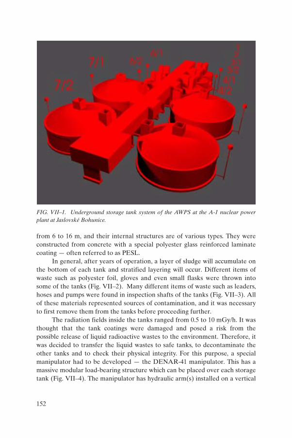
from 6 to 16 m, and their internal structures are of various types. They were constructed from concrete with a special polyester glass reinforced laminate coating — often referred to as PESL.
In general, after years of operation, a layer of sludge will accumulate on the bottom of each tank and stratified layering will occur. Different items of waste such as polyester foil, gloves and even small flasks were thrown into some of the tanks (Fig. VII–2). Many different items of waste such as leaders, hoses and pumps were found in inspection shafts of the tanks (Fig. VII–3). All of these materials represented sources of contamination, and it was necessary to first remove them from the tanks before proceeding further.
The radiation fields inside the tanks ranged from 0.5 to 10 mGy/h. It was thought that the tank coatings were damaged and posed a risk from the possible release of liquid radioactive wastes to the environment. Therefore, it was decided to transfer the liquid wastes to safe tanks, to decontaminate the other tanks and to check their physical integrity. For this purpose, a special manipulator had to be developed — the DENAR-41 manipulator. This has a massive modular load-bearing structure which can be placed over each storage tank (Fig. VII–4). The manipulator has hydraulic arm(s) installed on a vertical
FIG. VII–1. Underground storage tank system of the AWPS at the A-1 nuclear power plant at Jaslovské Bohunice.
152

FIG. VII–2. Example of the situation at the bottom of tanks at the A-1 nuclear power plant at Jaslovské Bohunice.
FIG. VII–3. Example of the situation in an inspection shaft at the A-1 nuclear power plant at Jaslovské Bohunice.
153
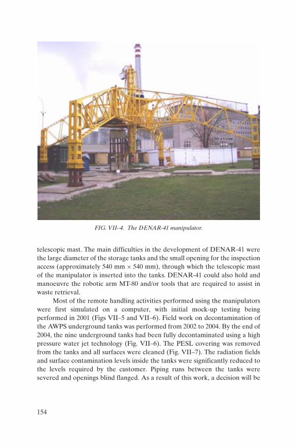
telescopic mast. The main difficulties in the development of DENAR-41 were the large diameter of the storage tanks and the small opening for the inspection access (approximately 540 mm × 540 mm), through which the telescopic mast of the manipulator is inserted into the tanks. DENAR-41 could also hold and manoeuvre the robotic arm MT-80 and/or tools that are required to assist in waste retrieval.
Most of the remote handling activities performed using the manipulators were first simulated on a computer, with initial mock-up testing being performed in 2001 (Figs VII–5 and VII–6). Field work on decontamination of the AWPS underground tanks was performed from 2002 to 2004. By the end of 2004, the nine underground tanks had been fully decontaminated using a high pressure water jet technology (Fig. VII–6). The PESL covering was removed from the tanks and all surfaces were cleaned (Fig. VII–7). The radiation fields and surface contamination levels inside the tanks were significantly reduced to the levels required by the customer. Piping runs between the tanks were severed and openings blind flanged. As a result of this work, a decision will be
FIG. VII–4. The DENAR-41 manipulator.
154

FIG. VII–5. Mock-up testing of the cutting of underground tanks at the A-1 nuclear power plant at Jaslovské Bohunice.
FIG. VII–6. High pressure water jet decontamination used at the A-1 nuclear power plant at Jaslovské Bohunice.
155

taken as to whether the results of the decontamination will allow for the tanks to be reused for purposes other than liquid radioactive waste storage.
A new movable cementation facility was developed for cementation of the radioactive sludges retrieved from the nine underground tanks (Fig. VII–8). It was considered that the project to decontaminate the AWPS underground tanks had been successfully completed — within schedule and under budget.
Moreover, within the framework of the decommissioning project for the A-1 nuclear power plant, another remote technology, a so-called ‘sludge walker’, has been developed. It is currently being used for retrieval of sludge from the bottom of another underground tank (Fig. VII–9).
VII–3. DECOMMISSIONING OF THE SOLID RADIOACTIVE WASTE STORAGE FACILITY
A system of external underground solid waste storage tanks was used for storage of solid wastes generated at the A-1 nuclear power plant. The Slovak
FIG. VII–7. Example of the state after decontamination of the surface of an underground tank at the A-1 nuclear power plant at Jaslovské Bohunice.
156
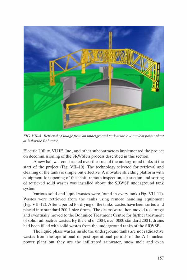
Electric Utility, VUJE, Inc., and other subcontractors implemented the project on decommissioning of the SRWSF, a process described in this section.
A new hall was constructed over the area of the underground tanks at the start of the project (Fig. VII–10). The technology selected for retrieval and cleaning of the tanks is simple but effective. A movable shielding platform with equipment for opening of the shaft, remote inspection, air suction and sorting of retrieved solid wastes was installed above the SRWSF underground tank system.
Various solid and liquid wastes were found in every tank (Fig. VII–11). Wastes were retrieved from the tanks using remote handling equipment (Fig. VII–12). After a period for drying of the tanks, wastes have been sorted and placed into standard 200 L size drums. The drums were then moved to storage and eventually moved to the Bohunice Treatment Centre for further treatment of solid radioactive wastes. By the end of 2004, over 3000 standard 200 L drums had been filled with solid wastes from the underground tanks of the SRWSF.
The liquid phase wastes inside the underground tanks are not radioactive wastes from the operational or post-operational periods of the A-1 nuclear power plant but they are the infiltrated rainwater, snow melt and even
FIG. VII–8. Retrieval of sludge from an underground tank at the A-1 nuclear power plant at Jaslovské Bohunice.
157

groundwater intrusion. The liquid materials are pumped out of the tanks and treated by use of the standard treatment methods for liquid radioactive wastes. Empty underground tanks are then inspected, isolated against groundwater and their integrity checked for a future decision as to their reuse or disposal.
VII–4. CONCLUSIONS
On the basis of this experience, the following conclusions can be drawn about the decommissioning of underground structures:
(a) Experience shows that the documentation available about older structures and systems is not very often about them as they were built and is sometimes missing altogether. Therefore, it is useful to take advantage of the various technologies available to assist in acquiring missing as-built data (for example, laser scanning, photogrammetry and videogrammetry) for the creation of as-built (three dimensional) conditions and documentation during the preparation phase of decommissioning.
(b) The development and use of advanced remote handling technology is possible, but the advantages and disadvantages must be thoroughly and
FIG. VII–9. A so-called ‘sludge walker’ at the A-1 nuclear power plant at Jaslovské Bohunice.
158

carefully assessed in advance before deciding on a course of action using a particular technology (for example, the remote handling technology for decontamination of the AWPS underground tanks).
FIG. VII–10. The solid radioactive waste storage facility at the A-1 nuclear power plant at Jaslovské Bohunice.
159

The use of commercially available techniques and modifications to these tools along with a combination of specially designed decommissioning equipment can help to reduce the cost and time of preparation for this type of work (for example, the technology for retrieval of the solid wastes and liquid phase from the SRWSF underground tanks).
FIG. VII–11. Example of the wastes inside the SRWSF tanks at the A-1 nuclear power plant at Jaslovské Bohunice.
160

FIG. VII–12. Retrieval of solid wastes from the SRWSF tanks at the A-1 nuclear power plant at Jaslovské Bohunice.
161
Annex VIII
EXPERIENCE WITH UNDERGROUND PIPELINES AND DUCTSAT THE CIRUS REACTOR, INDIA
VIII–1. INTRODUCTION
Cirus is a 40 MW(th) research reactor located at Trombay, Mumbai, India. The reactor has been in operation since 1960. The reactor, being of an earlier design, has several pipelines, ducts, tanks and other services situated underground. The reactor was shut down in late 1997 for refurbishment work related to life extension. During the refurbishment, many of the underground pipelines and some ducts were taken out of service and decommissioned. Some of the experience with this work is described here.
VIII–2. UNDERGROUND PIPELINES AT THE CIRUS REACTOR
VIII–2.1. Description of underground pipelines
The Cirus reactor uses light water as a coolant. The primary coolant system piping is connected directly with other components, namely recirculation pumps, heat exchangers, expansion tank, emergency water reservoir and underground dump tanks, to the reactor core.
All these components are situated in different parts of the complex and the connected piping is buried underground at various depths of up to 5 m. Since the pipes are laid in open areas, the soil cover acts as radiation shielding. The pipes vary from 20 to 500 mm in diameter. Lengths of pipe several hundred metres long containing both active and inactive liquids are laid below ground. Some of the larger size pipes are joined by expansion joints (dresser couplings) that use elastomer rings for sealing (Fig. VIII–1).
The area being close to the sea, the water table is high, and all of these pipelines are submerged in groundwater. For monitoring the leakage of radioactive water from these pipes, apart from monitoring the inventory loss, an array of bore wells was provided in the early 1990s. Regular monitoring of bore well water samples is performed for detection of radioactivity migration.
Subsequent to laying of these pipes, the centre has expanded, with one internal road and a central avenue road being constructed over these pipes.
162
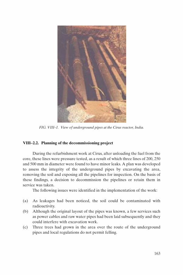
VIII–2.2. Planning of the decommissioning project
During the refurbishment work at Cirus, after unloading the fuel from the core, these lines were pressure tested, as a result of which three lines of 200, 250 and 500 mm in diameter were found to have minor leaks. A plan was developed to assess the integrity of the underground pipes by excavating the area, removing the soil and exposing all the pipelines for inspection. On the basis of these findings, a decision to decommission the pipelines or retain them in service was taken.
The following issues were identified in the implementation of the work:
(a) As leakages had been noticed, the soil could be contaminated with radioactivity.
(b) Although the original layout of the pipes was known, a few services such as power cables and raw water pipes had been laid subsequently and they could interfere with excavation work.
(c) Three trees had grown in the area over the route of the underground pipes and local regulations do not permit felling.
FIG. VIII–1. View of underground pipes at the Cirus reactor, India.
163

(d) The central avenue road had constant traffic and it was not possible to close it.
(e) The pipes were submerged in the groundwater, and continuous dewatering would be necessary.
(f) In the case that radioactivity was found in water, large volumes of water may have to be sent to the liquid waste effluent treatment plant.
(g) The work had to be performed in non-monsoon (rainy season) periods to avoid filling up of the pits with rainwater and washing of soil to other areas.
(h) In case large lengths of pipe needed to be decommissioned, arrangements to move them to the solid waste management facility and storage space should be available.
VIII–2.3. Execution of decommissioning plan
A comprehensive plan for excavation was prepared, discussed and reviewed by safety committees, and final approval was obtained. The plan was finalized and executed as follows:
(a) A thorough radiation survey of the area to be excavated and of adjacent areas was performed, and radiation fields were recorded as baseline data.
(b) Soil samples were collected from the surface soils and analysed for radioactivity.
(c) The area was cordoned off and movement of personnel, equipment and vehicles was restricted. No traffic was allowed on the internal road.
(d) After permission had been obtained from the forestry authorities, the three trees were removed and transplanted to a new location.
(e) Since the underground services subsequently laid were up to 1.2 m below ground, it was decided to excavate up to this depth manually with hand tools. Subsequent excavation up to pipe top elevation could be carried out with mechanical excavators.
(f) Arrangements were made to monitor the radioactivity from the soil and the water.
(g) If radioactivity was identified in the soil, it was to be segregated and stored in drums for disposal as radioactive waste.
(h) Continuous dewatering arrangements were made, with provision to divert the water to the liquid waste effluent treatment plant.
(i) The work was divided into two phases. In the first phase, the area other than the central avenue road region was covered. After completion of the work in the adjoining area to the road, a bypass road was constructed and the traffic diverted to use this bypass road (Fig. VIII–2). In the second
164

phase, the central avenue road was dug up for excavation and work on the pipelines.
VIII–2.3.1. Activity characterization
Samples from several primary coolant components were analysed for activity characterization. The results showed 137Cs to be the dominant fission product and 60Co to be the dominant activation product. Other radionuclides — 90Sr, 124Sb, 144Ce, 152Eu, 65Zn, 154Eu, 95Nb and 110Ag — were also present in small quantities.
For the pipelines, an average activity of 6.6 Bq/g was estimated, with the contribution from fission products ranging from 50 to 90% and the balance being from activation products. The radiation fields on these pipes were less than 1 mR/h (10 mGy/h).
FIG. VIII–2. View of the main road blocked off and traffic diverted to a bypass road in order to allow access to the pipes below the main road at the Cirus reactor, India.
165

VIII–2.3.2. Excavation
After the initial preparations, the excavation work was performed in phases. An initial depth of 1.2 m was manually excavated to locate any other underground services. Subsequently the mechanical excavators were employed to reach down to pipe top surfaces. Soil above and below the pipes was again removed manually to avoid damage to the pipes. Since the pits were deeper, wooden barriers were used on the sides with horizontal props wherever necessary to prevent collapse of the soil. Soil was kept wet by sprinkling water during excavation. The pits were dewatered with electrically driven pumps, and diesel engine driven pumps were kept on standby.
VIII–2.3.3. Radiological precautions
During excavation, the dose rates emanating from the soil were monitored. Although these were found to be low, higher radiation fields were encountered in some areas during excavation. Maximum radiation fields of 15 mR/h (0.15 mGy/h) were measured near to the pipes in the soil at a few locations. In the majority of these areas, the radiation fields in the soil were at the background level.
Soil samples in different areas and at different depths were collected for radioactivity analyses. It was found that 137Cs is the dominant radionuclide, with traces of 134Cs, 152Eu and 154Eu. Specific activity ranged from 56 to 1600 Bq/g. This was caused by leakage from the pipes while in service and by leakage of radioactivity into the surrounding soil.
VIII–2.3.4. Soil handling
Soil that showed high radiation fields and contamination was segregated and filled into drums. The remainder of the soil was heaped outside the excavated pits and used for backfilling. A total of more than 8000 m3 of soil was excavated, and approximately 56 m3 of soil containing about 11 625 MBq of activity was segregated as contaminated soil.
VIII–2.3.5. Removal of pipes
On the basis of detailed examination of pipes, the pipes that needed to be removed were identified. Since the area was open with no confinement, thermal cutting was avoided to prevent airborne activity spreading into adjacent areas. The pipes were mechanically cut with power saws and hacksaws. Cut pipes were wrapped in polythene sheets and lifted out of the pits with the
166
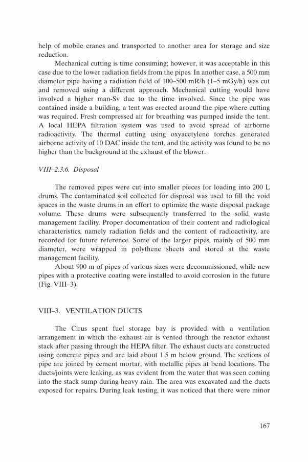
help of mobile cranes and transported to another area for storage and size reduction.
Mechanical cutting is time consuming; however, it was acceptable in this case due to the lower radiation fields from the pipes. In another case, a 500 mm diameter pipe having a radiation field of 100–500 mR/h (1–5 mGy/h) was cut and removed using a different approach. Mechanical cutting would have involved a higher man-Sv due to the time involved. Since the pipe was contained inside a building, a tent was erected around the pipe where cutting was required. Fresh compressed air for breathing was pumped inside the tent. A local HEPA filtration system was used to avoid spread of airborne radioactivity. The thermal cutting using oxyacetylene torches generated airborne activity of 10 DAC inside the tent, and the activity was found to be no higher than the background at the exhaust of the blower.
VIII–2.3.6. Disposal
The removed pipes were cut into smaller pieces for loading into 200 L drums. The contaminated soil collected for disposal was used to fill the void spaces in the waste drums in an effort to optimize the waste disposal package volume. These drums were subsequently transferred to the solid waste management facility. Proper documentation of their content and radiological characteristics, namely radiation fields and the content of radioactivity, are recorded for future reference. Some of the larger pipes, mainly of 500 mm diameter, were wrapped in polythene sheets and stored at the waste management facility.
About 900 m of pipes of various sizes were decommissioned, while new pipes with a protective coating were installed to avoid corrosion in the future (Fig. VIII–3).
VIII–3. VENTILATION DUCTS
The Cirus spent fuel storage bay is provided with a ventilation arrangement in which the exhaust air is vented through the reactor exhaust stack after passing through the HEPA filter. The exhaust ducts are constructed using concrete pipes and are laid about 1.5 m below ground. The sections of pipe are joined by cement mortar, with metallic pipes at bend locations. The ducts/joints were leaking, as was evident from the water that was seen coming into the stack sump during heavy rain. The area was excavated and the ducts exposed for repairs. During leak testing, it was noticed that there were minor
167

leaks from many joints and there were also some cracks in the concrete pipes, while the metallic pipes were found to be rusted due to damage to their external coating. All of these concrete pipes and the metallic joints were then removed after breaking joints with tile cutters and hand tools. These concrete pipes were disposed of as solid radioactive wastes and new pipes were installed (Fig. VIII–4). The wastes resulting from these decommissioning activities were composed of a total of 13 m3 of concrete pipes containing 3 MBq of activity.
VIII–4. NORMALIZING THE LANDSCAPE
After the work had been completed on these underground pipes and ducts, and backfilling was also complete, a detailed radiation mapping was carried out. This was compared with the baseline data to detect any changed condition. Few areas showed higher radiation levels. Limited excavation in
FIG. VIII–3. View of the underground pipes near completion of work at the Cirus reactor, India.
168

those areas with radiation monitoring was carried out to remove the radioactively contaminated soil, after which clean soil was used as backfill. Subsequently the area was covered with stone tiles to avoid growth of vegetation.
VIII–5. CONCLUSIONS
The experience with underground pipelines and ducts at the Cirus reactor in India allows the following conclusions to be drawn:
(a) Proper records of ‘as-built’ drawings can help to avoid unnecessary excavations.
(b) Proper planning helps to deal with unforeseen events. (c) Constant radiological monitoring is necessary during excavation work.
This will indicate whether there have been leakages and avoid spread of contamination.
FIG. VIII–4. New underground ventilation concrete pipes being laid after removal of the old pipes at the Cirus reactor, India.
169

(d) If the soil is contaminated, it is necessary to segregate it properly and avoid mixing with uncontaminated soil.
(e) No services such as roads or cabling should be laid over these underground pipes and ducts. Similarly, wild vegetation and trees should be avoided in such areas.
BIBLIOGRAPHY TO ANNEX VIII
KHARPATE, A.V., “Engineering considerations and experience related to refurbishment and safety up-gradation of 40 MW(th) CIRUS research reactor”, Research Reactor Utilization, Safety, Decommissioning, Fuel and Waste Management (Proc. Int. Conf. Santiago, 2003), IAEA, Vienna (2004) 227.
RAO, D.V.H., et al., “Life extension and refurbishment of piping systems in Cirus”, paper presented at IAEA-RCA Seminar on Ageing Management of Research Reactors, Mumbai, 2000.
SANKAR, S., “Planning and management of refurbishment work of CIRUS”, Research Reactor Utilization, Safety and Management (Proc. Symp. Lisbon, 1999), C&S Papers Series No. 4/C, IAEA, Vienna (2000) paper IAEA-SM-360/45 (CD-ROM).
SANKAR, S., et al., “Generation of database for future decommissioning of CIRUS”, Decommissioning Techniques for Research Reactors, IAEA-TECDOC-1273, IAEA, Vienna (2002).
170

Annex IX
STRATEGY FOR DECOMMISSIONING OF UNDERGROUND PIPES AT THE NATIONAL INSTITUTE OF ONCOLOGY AND
RADIOBIOLOGY IN HAVANA, CUBA
IX–1. INTRODUCTION
The National Institute of Oncology and Radiobiology (INOR) was one of the first institutions in Cuba that applied ionizing radiations in medicine. At the beginning of the 1980s, no centralized storage facility for radioactive wastes was in operation in Cuba. A room at INOR was then used as a storage facility for disused sealed sources from nuclear applications in medicine and industry. This room was located in a facility that had been used for brachytherapy services. At least one of the 137Cs sources stored in this area was leaking, causing radioactive contamination in the eight rooms belonging to the former brachytherapy service.
Different decontamination and dismantling activities were carried out in the facility between 1988 and 1999. However, for different reasons, the requirements established by the National Center for Nuclear Safety (the regulatory authority) for decommissioning could not be achieved, and therefore the facility could not be released from regulatory control. The facility was closed because of the remaining contamination.
Final decommissioning activities were started again in 2004. One of the key issues considered was decommissioning of the underground pipes located in the facility. Figure IX–1 shows a plan of the contaminated areas. This annex presents the strategy selected for decommissioning of the underground pipes, taking into consideration technical and financial aspects, as well as the regulatory requirements established by the regulatory authority.
IX–2. DESCRIPTION OF THE PROBLEM
No regulations to address decommissioning were in place in Cuba in the 1980s. This resulted in a lack of early consideration of, and planning for, decommissioning at the brachytherapy facility of INOR. When contamination was detected, some attempts were made but the facility remained closed for more than 20 years.
171

Dismantling and decontamination activities were first carried out in 1988. At that time, cleaning with water and detergent solutions was the method used for decontamination of the walls and floors. The use of water caused the spread of contamination to other areas not contaminated earlier, for instance the garden and the underground drainage pipes. Decommissioning could not be completed at that time and the facility was again closed.
In 1997 the hospital requested the Center for Radiation Protection and Hygiene (Havana) to decommission the facility. The radiological situation was evaluated and the first decommissioning plan was formulated. The characterization and decommissioning strategy for the underground pipes was not described in detail in the decommissioning plan from the beginning. The pipes were located below the contaminated floor and neither drawings of the location of the pipes in the facility nor appropriate equipment for measurements inside the pipes were available, and hence it was not possible to characterize the underground pipes during the first radiological evaluation.
Some decontamination and dismantling activities were carried out in 1999, when radiation and contamination levels were significantly reduced. Because of the high levels of contamination in the area and the requirements established by the regulatory authority for clearance (surface contamination of 0.4 Bq/cm2), the decommissioning of the facility would have been an extremely
(15 m2)
(7.5 m2) (3.5 m2)
(30 m2)
4
5 6
2
1
3(6.0 m2)
7
8
(19 m2)
(19.5 m2)
Garden
¤¤
¤
Garden
FIG. IX–1. Plan of contaminated areas at INOR, Havana. The traps of the contaminated underground pipes are shown in red.
172

expensive undertaking. The cost would have been mainly related to management of the large amount of radioactive wastes generated. For these reasons, it was decided not to continue decontamination activities. The surface of the floor in all the areas was then covered with plastic sheeting to avoid the spread of radioactive contamination.
A new decommissioning strategy with more realistic dose criteria was then elaborated and presented to the regulatory authority for approval in 2002. INOR received authorization for decommissioning in 2003.
IX–3. TECHNICAL AND FINANCIAL CONSIDERATIONS
Technical and financial considerations must be taken into account for decommissioning of the underground pipes in the new strategy adopted.
Adequate equipment for radiological characterization of underground components was not available, nor was it possible to buy suitable equipment. INOR did not have proper funding for decommissioning. These activities were supported with limited financial resources provided by government authorities.
Assessment of the internal contamination in pipes by measuring the radiation levels outside was not possible because the pipes were located under contaminated floor tiles and construction filling materials. The only point that was available for direct measurement was the trap.
IX–4. STRATEGY ADOPTED
IX–4.1. General considerations for the facility
The decommissioning plan contained the radiological criteria proposed to the regulatory authority for decommissioning of the facility: the annual dose received by members of the public should not be above the natural background by more than 0.3 mSv. On the basis of this criterion, the following operational reference levels were derived:
(a) The dose rate at 10 cm from any surface (walls, floors or roofs) should not exceed the natural background by more than 0.1 mSv/h.
(b) The surface contamination in specific objects should not exceed 30 Bq/cm2.
(c) The specific activity in the soil (in the garden and floor filling materials) should not exceed 1 Bq/g.
173

The regulatory authority approved these criteria. The operational magnitudes were used during dismantling and decontamination activities, as well as for the final radiological survey in all areas. The strategy adopted for the decommissioning of the facility was to remove contaminated tiles, soil, parts of the walls, etc., until the dose rate at 10 cm from the surface was less than 0.1 mSv/h above the natural background. Criteria based on surface contamination and specific activities were used to evaluate whether different materials or objects should be considered as radioactive wastes.
IX–4.2. Strategy for characterization of underground pipes
The strategy adopted for characterization of the underground pipes at INOR was to remove the contaminated tiles and floor filling materials on them. After this, the activity of 137Cs was estimated according to the following procedure:
(a) First, it was considered that the use of water in previous decontamination activities had caused the spread of contamination to the underground drainage pipes. This contamination was distributed along the pipes; since a considerable quantity of water had been used for washing (in the form of pressurized water jets), the gradient of contamination was considered to be very small, and therefore a uniform distribution of activity along the pipe was assumed.
(b) It was verified that the dose rate measured was coming from only the pipe and not from other contaminated materials (such as floor tiles or filling). Using a dose rate monitor with a collimator, the dose rate was measured on the surface of the floor, where the pipe was supposed to be (Fig. IX–2).
FIG. IX–2. Dose rate monitoring on a floor surface at INOR, Havana.
174

(c) The dose rate was measured at a distance a from the pipe. The point of measurement should be located on an imaginary line perpendicular to the pipe, as shown in Fig. IX–3, where L was the length of the pipe. The distance a should be ten times the diameter of the pipe, in order to consider the pipe as a linear source.
(d) After the dose rate was measured, expression (IX–1) below was used to calculate the activity of 137Cs per unit pipe length (Bq/cm):
(IX–1)
where:
H· is the dose rate, in Sv · h–1 or (0.01 × dose rate in R · h–1);a is the distance between the detector and the centre of the pipe (cm);G is the gamma constant for 137Cs (= 9.1 × 10⁻¹⁰ Sv · h–1 · cm2 · Bq–1);L is the length of the pipe (cm) and AL is the activity of 137Cs per unit length of pipe (Bq · cm–1).
The attenuation produced by pipe walls was not considered, as they had a thickness of a few millimeters of iron or the equivalent.
(e) An analogue formulation could also be applied to the other geometry encountered; for example, to calculate the activity using the dose rate measured at a distance a from the extreme of a lineal source (Fig. IX–4). The parameters are the same as those in expression (IX–1):
(IX–2)
a Detector
L
FIG. IX–3. Geometry for measurement of the dose rate from a pipe at INOR, Havana.
AHa
La
L =ÊËÁ
ˆ¯̃
-
�
22
1G tan
�HA
aLa
L= ÊËÁ
ˆ¯̃
-Gtan .1
175

IX–5. RESULTS OF THE CHARACTERIZATION AND DECOMMISSIONING OF UNDERGROUND PIPES
IX–5.1. Traps
At the beginning of decommissioning activities, three traps of contaminated underground pipes were found. They were located in rooms 4 and 7 of the facility (Fig. IX–1).
In room 7, as the dose rate at 10 cm from the surface of the floor around the traps was above the reference levels, the traps had to be removed, as well as the surrounding filling material. These activities are shown in Fig. IX–5.
A considerable amount of soil was removed — a hole 50 cm deep was made. Nevertheless, the reference level in terms of dose rate was not reached. As the dose rates at the surface of the hole were not significant (1–4 mSv/h) and continuing with removal of contaminated soil would have generated a considerable amount of radioactive wastes, the strategy for decommissioning was then changed to entombment. It was proposed to remove contaminated materials until the dose rate at the level of the floor was 1 mSv/h. This strategy was based on the assumption that some construction work was needed for release of the facility from regulatory control. The hole must be filled with soil or other materials, which at the same time would serve as shielding. The annual dose received by a person working or living in this room was calculated and found to be well below 0.3 mSv.
Contamination levels in the traps of room 4 were lower. It was verified that one of the pipes in this room was connected to the drainage system of the hospital, as the water flow was seen inside. The entrances of traps were closed (in order to avoid contaminated materials entering the pipe), and surrounding
a
Detector
L
FIG. IX–4. Geometry for calculating the activity at INOR, Havana, using expression (IX–2).
176

contaminated filling was removed. The trap was then removed and the dose rate inside the drainage pipe was measured. It was 1 mSv/h, and the pipe was left in place (Fig. IX–6).
Two sinks in room 4 were connected to the other traps. The pipes installed between the sinks and the traps were contaminated. One of these was
FIG. IX–5. Removal of traps and surrounding material at INOR, Havana.
177

embedded in the wall and the other under the floor. Both were removed. As the dose rate at 10 cm from the traps was below the clearance levels, they were left in place (Fig. IX–7).
FIG. IX–6. Final decommissioning activities at INOR, Havana.
FIG. IX–7. Final survey for decommissioning at INOR, Havana.
178
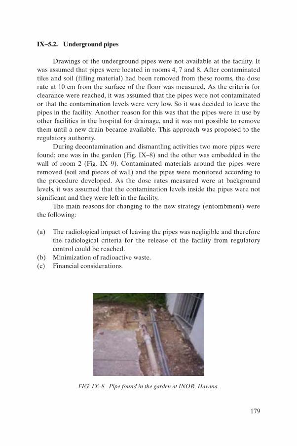
IX–5.2. Underground pipes
Drawings of the underground pipes were not available at the facility. It was assumed that pipes were located in rooms 4, 7 and 8. After contaminated tiles and soil (filling material) had been removed from these rooms, the dose rate at 10 cm from the surface of the floor was measured. As the criteria for clearance were reached, it was assumed that the pipes were not contaminated or that the contamination levels were very low. So it was decided to leave the pipes in the facility. Another reason for this was that the pipes were in use by other facilities in the hospital for drainage, and it was not possible to remove them until a new drain became available. This approach was proposed to the regulatory authority.
During decontamination and dismantling activities two more pipes were found; one was in the garden (Fig. IX–8) and the other was embedded in the wall of room 2 (Fig. IX–9). Contaminated materials around the pipes were removed (soil and pieces of wall) and the pipes were monitored according to the procedure developed. As the dose rates measured were at background levels, it was assumed that the contamination levels inside the pipes were not significant and they were left in the facility.
The main reasons for changing to the new strategy (entombment) were the following:
(a) The radiological impact of leaving the pipes was negligible and therefore the radiological criteria for the release of the facility from regulatory control could be reached.
(b) Minimization of radioactive waste.(c) Financial considerations.
FIG. IX–8. Pipe found in the garden at INOR, Havana.
179

IX–6. POSITION OF THE REGULATORY AUTHORITY
After dismantling and decontamination activities had been completed, a radiological survey was performed at the facility and the final report was presented to the regulatory authority. The new strategy adopted for decommissioning was described and presented for approval.
The regulatory authority evaluated the proposal and carried out an inspection of the facility. It was considered that dismantling and decontamination activities could be stopped, taking into consideration the fact that subsequent activities would not entail significant reductions in the radiation and contamination levels. The following requirements for decommissioning were established by the regulatory authority:
(a) The dose rate from any surface should not exceed the natural background by more than 0.1 mSv/h. Necessary shielding should be guaranteed where this level was reached.
(b) Humans should be isolated from contaminated materials. Regarding the underground pipes, it was required that no maintenance or repair activities be performed in the contaminated areas (mainly around the traps). Therefore the drainage for the contaminated area should be closed and new drains must be constructed outside. Use of the existing drainage should cease.
FIG. IX–9. Pipe embedded in a wall at INOR, Havana.
180

IX–7. LESSONS LEARNED
The most important lessons learned during the decommissioning activities at INOR are the following:
(a) Consideration and planning of decommissioning are extremely important from the very beginning — from the design, construction and commissioning of a facility. It is also very important to maintain appropriate records about the construction and operation of the facility.
(b) Cleaning by washing with a considerable amount of water or other solution for decontamination should be previously evaluated. This method is not always very efficient and may only cause the spread of contamination to other areas, mainly when the contamination is caused by soluble compounds such as caesium salts.
IX–8. CONCLUSIONS
The conclusions drawn from the decommissioning activities at INOR are the following:
(a) The strategy for decommissioning of underground pipes has changed during the D&D process. The decision for leaving them underground has been thoroughly analysed and justified from the radiological, technical and economic viewpoints.
(b) The INOR facility has finally been decontaminated and decommissioned. The regulatory authority has approved the final release of this facility from regulatory control.
181

Annex X
LESSONS LEARNED DURING DECOMMISSIONING OF UNDERGROUND STRUCTURES, SYSTEMS AND COMPONENTS
X–1. INTRODUCTION
The following examples present some important lessons learned, some brief technical details and a description of problems encountered in the past in various decommissioning projects related to the removal of underground SSCs. Some cases refer to embedded components.
The situations described here are typical of the types of difficulty that can arise when planning for or implementing the removal of underground SSCs as an element of the decommissioning process.
The information presented here is not intended to be exhaustive and the reader is encouraged to evaluate the applicability of the specific lessons learned to their own particular decommissioning project or activity. It is not the intention of this annex to identify projects for criticism but rather to enhance future operations planning and implementation in order to reduce the likelihood of the recurrence of earlier problems. A short analysis of the root causes of these problems is presented in Table X–1, which classifies different projects according to a set of slightly different root causes.
The following are summaries of operational experiences as they relate to the decommissioning of underground components:
(a) The most frequent problem experienced during projects is lack of records or appropriately detailed records such as as-built drawings, photographs or models of the systems and components embedded in the underground environment. The exact dimensions and locations may be unknown, and in many cases are not even identified on drawings. It should be emphasized that in order to overcome this problem the characterization phase of a project might even need to be further expanded to address this matter.
(b) The second most frequently encountered problem is inadequate or completely absent characterization programmes. This should alert the project manager and the decommissioning staff to the fact that even existing site characterization and sampling data should be regarded a priori as insufficient and be treated with care. Additional samples might need to be collected and special analyses made to fully discover the
182

TABLE X–1. ROOT CAUSES OF PROBLEMS ENCOUNTERED IN DECOMMISSIONING OF UNDERGROUND SSCs
Example(Annex section number)
Root causesa
A B C D E F G H
X–2 (Belgium) X
X–3 (USA) X
X–4 (USA) X X X
X–5 (USA) X X
X–6 (USA) X X X
X–7 (USA) X X
X–8 (USA) X X X
X–9 (USA) X X
X–10 (USA) X X X X
X–11 (USA) X X
X–12 (USA) X X X
X–13 (USA) X X
X–14 (USA) X
X–15 (USA) X X X
X–16 (UK) X X
X–17 (UK) X
X–18 (UK) X X
X–19 (Spain) X Xa Explanations of root causes leading to problems:
A: Facility layout — Narrow spaces between pipes, no access foreseen for inspections or maintenance, no use of double walled piping or drip pans, etc.
B: Material selection — Construction material of piping or tankage exceeds design life and there has not been sufficient inspection of its state to verify its continued proper functioning.
C: Lack of records — Insufficient records available on the exact location and dimensions of embedded parts.
D: Unverified records — Incorrect interpretation or verification of available information.
E: Characterization programmes — Insufficient characterization data available.F: Lack of a decommissioning strategy — Lack of a clear project strategy for how to
reach the final decommissioning end point.G: Waste management — Waste disposition routes must be defined from the start of
the project and include waste conditioning, packaging and storage/disposal.H: Deactivation of utility services — Incidents resulting from poor deactivation
practices.
183

conditions in which the work will need to be performed, instead of those originally envisioned and gleaned from earlier data.
(c) The third most frequently encountered problem is lack of timely deactivation of utility services. This should again alert the project manager and the decommissioning staff and plant operators to the fact that it is critical to ensure that any service line in the vicinity of the embedded structures should be logged out and/or deactivated.
X–2. DECOMMISSIONING OF THE MOLSE NETE DISCHARGE LINE, BELGOPROCESS, BELGIUM
X–2.1. Statement of problem
During the dismantling of the facilities at Molse Nete [X–1], the main objective of the project was to remove a total length of 10 km of piping that was embedded underground and used for connecting a laboratory and a waste treatment facility. In the process, emphasis was placed on producing as small a volume of radioactive wastes as possible, while still completing the work. See also Annex I.
The whole pipe was expected to be only slightly contaminated and was excavated, with all necessary precautions being taken (Fig. X–1), and then directly cut into segments and placed into plastic bags (Fig. X–2). The total volume of wastes produced amounted to about 50 m³ (approximately 10 t).
X–2.2. Solution found
In order to minimize the radioactive wastes generated from this work, it was decided to attempt to decontaminate the cut piping segments. The decontamination procedure was first tested on a small batch (of about 5 m³ volume). The pipes were first cut open to expose their internal surfaces for direct contact measurements. The results of these contamination measurements were then used to develop a pipe treatment procedure for the remaining 45 m³ of piping. This procedure was approved by the Belgian Health Physics Service and the Belgian regulatory authority (Fig. X–3).
The process consisted of the following steps:
(a) Cut each section of pipe into four segments by use of hydraulic scissors (to avoid aerosol production and the secondary wastes the scissors would generate).
184

(b) Perform direct contact measurement for free release (note that the general SCK·CEN procedure for free release of materials foresees two separate measurements on the same piece of equipment) allowing ‘contaminated’ material to be differentiated from ‘releasable’ material.
(c) Decontaminate the contaminated waste items using water and a decontamination solution. The wash-water is considered to be a secondary waste.
(d) Perform a new direct contact measurement.(e) Wash a 20% sample of the releasable material in the same way as the
contaminated material portion. The wash-water is analysed, and this measurement is used as a second measurement for the free release.
Using this process, a total of 50 m³ was decontaminated and a certificate of free release was granted by the Health Physics Service after approval from the regulatory authority.
FIG. X–1. Excavation of a pipe in connection with Molse Nete discharge line decommissioning, Belgium.
185

X–2.3. Lessons learned
The lessons learned during this project are as follows:
(a) A thorough review and analysis of operational records is a key phase of the evaluation of project risk and of the problems to be addressed.
(b) The decommissioning of embedded piping can be performed using simple techniques with existing tools provided that the work is efficiently organized and planned.
(c) The waste management and minimization aspect of the work is very important since it has a major impact on the total decommissioning cost (there can be an impact on this from the national waste disposal policy and the costs associated with its implementation).
FIG. X–2. The segments are cut on-site and placed in plastic bags, Molse Nete, Belgium.
186

Cut in four
Analyse wash-water
< FRL ?
Radwaste
Free release
(<FRL?)
Free release
NY
N
N
80%
Y
Y
N
Y
N
Work in batches
Directcontact< FRL?
Sample20%
Wash-waterand
decontamination
Wash-waterand
decontamination
Directcontact< FRL?
FIG. X–3. Measurement principle for the pipeline at Molse Nete, Belgium (Y: Yes; N: No; FRL: free release).
187

X–3. PNEUMATIC TRANSFER TUBE REMOVAL PROJECT, ANL EAST SITE, USA
X–3.1. Statement of problem
While removing a pneumatic transfer tube system between two buildings [X–2], a problem was encountered with water in the trench that had to be resolved during the project activities. After excavation, water would drain out of the adjacent sand areas and partially fill the trench. At one point, water entered the cut end of the tube before it could be raised above the water. The water was discovered when it spilled out of the tube and onto the ground.
X–3.2. Solution found
A barricade was erected around the area and the soil removed. The area was sampled to verify that all the contamination had been removed. The affected area was approximately 1 yd2 (0.836 m2). The remaining water was drained from the tube and collected.
X–3.3. Lessons learned
A plan should have been prepared and ready for implementation for the eventuality that water became trapped inside the tube. For example, a container could have been available to catch the contaminated water, thus avoiding spillage and subsequent cleanup of contaminated soil. The spill could have been avoided with better preparation and job planning.
X–4. BUILDING 34 DECOMMISSIONING, ANL EAST SITE, USA
X–4.1. Statement of problem
Building 34 at the ANL East Site [X–3] had previously served as an industrial wastewater treatment facility for industrial wastewater from several of the original research facilities. Undetected leakage in the past from the open-top concrete tanks, while they were still in operation, required remediation as a part of the decommissioning activity. This resulted in a larger than expected volume of radioactively contaminated waste soils which required packaging and disposal off-site.
188

X–4.2. Solution found
Past monitoring had not detected any leakage from the tanks and, therefore, no contingency was provided for such work within the scope of the project. This resulted in the unexpected expenditure of additional project funds for this work, to cover the costs of the excavation and disposal of the unexpected contaminated soil.
X–4.3. Lessons learned
Old facility tank systems are prone to leakage after many years of continuous use and, in some cases, less than adequate maintenance. In addition, there may be construction quality issues at some facilities, especially at older ones since the operating conditions for such facilities may have been less rigorous than for those currently in use. Some consideration should also be given to sampling in close proximity to all exterior features with piping and tankage. An additional contingency should also be considered allowing for some amount of unexpected wastes, which may require disposition.
X–5. CINTICHEM RESEARCH REACTOR, USA
X–5.1. Statement of problem
An underground ventilation duct system for the hot cell facility at the Cintichem research reactor [X–4] had leaked over the operational period during the processing of reactor materials into radiopharmaceuticals. The contaminated areas under these hot cells were deemed unsuitable for characterization and sampling in relation to planning the decommissioning of the facility. This was due to a concern over possible contamination of the soil underlying the area by contaminants in the hot cells. Instead, the area would be allowed to remain undisturbed until the decommissioning progressed to the point of hot cell demolition, after which the underlying soils would be remediated as necessary. This was intended to allow easy access to the contaminated soil area for remediation. The down gradient area from the reactor and hot cell was an area containing a drinking water supply for the local area.
189

X–5.2. Solution found
Early characterization (including intrusive activities) would have identified the significant leakage which had occurred over the years and had resulted in a very large volume of soil requiring removal and disposal to ensure that no contaminants reach the drinking water reservoir. More extensive and innovative techniques could have been used to investigate the issue of the contaminated soil under the hot cells.
X–5.3. Lessons learned
Inadequate characterization of areas can result in major problems leading to handling of unexpected and much larger volumes of contaminated soils. In order to minimize cost escalation due to these types of problem, a thorough and detailed characterization should be performed to properly define the scope of a project prior to starting the work.
X–6. HANFORD F-REACTOR, USA
X–6.1. Statement of problem
The USDOE Hanford Site F-Production Reactor [X–5] had a large discharge basin (6400 ft² (600 m²)) at the rear of the reactor block for discharging fuel into after irradiation. Fuel slugs were pushed from the front face of the reactor and out of the rear face of the reactor block. These fuel slugs were allowed to thermally cool before being transferred to other site facilities for further processing. When the reactor was closed, these basins were not properly deactivated to a safe shut down and verifiable condition. It was unclear if any full fuel elements or pieces of fuel elements remained in the basins after they were backfilled with sand to the top edge — a depth of about 20 ft (6 m).
X–6.2. Solution found
After removal of the void filling materials from the basins, the areas had to be carefully re-excavated in order to remove the sand used to fill them in the past. As these areas were unearthed and monitored for radiation levels, over a dozen different items (potentially fuel items) were discovered at the bottom of the basins. Several new technologies were used to assist with the retrieval of
190

these items, including laser assisted ranging and data collection systems, remote monitoring systems and a remotely operated excavator.
X–6.3. Lessons learned
Proper and timely deactivation of underground facilities is necessary prior to their placement into a safe storage condition. Although newer technologies assisted greatly in this effort, they also added to the project schedule and required funding, which could have been avoided had the facility been properly deactivated.
X–7. HANFORD NUCLEAR SITE, USA
This and several other examples have been extracted from a USDOE lessons learned database [X–6–X–11], which was accessible at the time this report was prepared. It is suggested that the reader investigate the availability of these data.
X–7.1. Statement of the problem
At the USDOE Hanford site [X–6], a work team which was removing abandoned underground utility pipes as part of the pre-job planning phase of the work discovered underground pipes that had not been previously identified on the facility as-built drawings. Additional research indicated that one of the pipes was a 6 in (15 cm) water pipe that had been capped off, depressurized and ‘abandoned’ in situ. With this additional information, the team decided to continue the dig by hand, to locate and verify the exact positions of the pipes.
X–7.2. Solution found
With the pipe located and its position verified, various procedures allowed the team to proceed with mechanical excavation and demolition of the 6 in (15 cm) water pipe and other identified utilities. Rather than proceed immediately, the team decided that with all the inconsistencies between the site drawings and the physical location of the water pipe, it would be prudent to verify that it was indeed depressurized. It was decided then to drill a 0.125 in (3.15 mm) hole in the water pipe to verify that it was depressurized.
Upon drilling the hole, pressurized water was encountered which did not exhibit the characteristics of residual pressure. The continuing water flow indicated that the pipe was not deactivated but was still pressurized. At this
191

point the contractor plugged the hole, and stopped work. By going beyond the procedural requirements and using standard industry practices, and good common sense, a work team avoided what could have been a serious loss of the fire suppression system and possible employee injury.
X–7.3. Lessons learned
Abandoned utility pipes should be treated as pressurized until proven otherwise, especially when their identity or condition is questionable. In this case, drilling a pilot hole provided an extra margin of safety.
X–8. EAST TENNESSEE TECHNOLOGY PARK (FORMER OAK RIDGE GASEOUS DIFFUSION PLANT), USA
X–8.1. Statement of problem
During the demolition of a uranium feed facility at the former Oak Ridge gaseous diffusion plant [X–7], a worker sheared an 8 in (20 cm) water pipe. A subcontractor was using a crane with an attached shearing device, capable of shearing steel beams and columns, to demolish the building, when a capped pressurized 8 in (20 cm) water pipe was cut. When the pipe break occurred, the shift supervisor was immediately notified and the utility pipe was isolated to stop leakage.
X–8.2. Solution found
All utility systems were identified at the start of the project and were thought to have been isolated prior to the start of demolition activities. A facility drawing indicated that a single 8 in (20 cm) underground water pipe entered the south side of the building, which was apparently associated with a previous process operation in the building. Upon further investigation following the incident, a different engineering drawing was located that indicated there was a 6 in (15 cm) underground fire-water pipe that fed a sprinkler system at the facility. The valve listed on the drawing did not actually isolate the 8 in (20 cm) pipe that entered the building but instead isolated the 6 in (15 cm) fire-water pipe. The 8 in (20 cm) pipe was not identified as a pipe that needed to be de-energized.
192

X–8.3. Lessons learned
Care should be taken to verify that correct facility as-built and as-modified drawings are consulted, and appropriate physical verification conducted when performing a lockout/tagout of hazardous energy sources or opening potentially pressurized pipes.
X–9. OAK RIDGE NATIONAL LABORATORY, USA
X–9.1. Statement of problem
Work activities involving the removal of five underground waste and process pipes at ORNL [II–8] to facilitate installation of a new tank vault were initiated in 1995. The initial site characterization data identified the pipeline contents to be a typical waste/sludge mixture of alpha and beta/gamma isotopes. The surrounding soils in the area where construction was going to occur were identified to be potentially Category 2 soil (contaminated but below 5 mrem/h (0.05 mSv/h) dose rate). Field surveys during the initial excavations resulted in the soil surrounding the pipelines being re-categorized as Category 3soil (i.e. contaminated to greater than 5 mrem/h (0.05 mSv/h) dose rate). In addition, during the initial excavation, a drain pipe was found in a location different from that shown on the design drawings. The work control process requires the cessation of affected activities when underground items not adequately identified by as-built drawings are encountered. The construction workers recognized the hazards, work was stopped immediately and plant personnel were contacted for additional information prior to work being resumed.
X–9.2. Solution found
Under these circumstances, a greater potential existed for personnel contamination from the Category 3 soil than was originally thought to have existed. The construction crew had a work control process in place to address and account for changes in field conditions such as inadequate soil characterizations and the legacy problem with as-built drawings not being updated. This work control process also allowed the construction manager to stop affected field activities until the unidentified underground items could be properly identified and characterized.
193

X–9.3. Lessons learned
Potential accidents such as human injuries or fatalities, equipment damage and/or costly project delays are avoided when a work control process is established to compensate for field work conditions which can often differ from those envisaged on the basis of the initial site characterization, as-built drawings, etc.
X–10. IDAHO NATIONAL ENGINEERING AND ENVIRONMENTAL LABORATORY, USA
X–10.1. Statement of problem
Workers were installing fence posts for a new fence under construction at the USDOE INEEL site [X–9] by using a hand-held digger for post holes. Prior to the start of digging, the ground was marked where to dig the holes. During the excavation process, the workers discovered that a buried 480 V electrical conduit had been broken by the work activities. Upon identifying the damaged equipment, work was stopped.
X–10.2. Solution found
The electrical system provided power to temporary project office trailers in the area. Since the power supply was temporary, no as-built drawings were available. Instead of marking the trace of the conduit on the surface to document where the conduit was in the subsurface, the ground was marked where the holes were to be dug. Work control procedures failed to identify that minor work activities require detailed hazard assessments to be performed and identified hazards to be mitigated prior to the start of work.
X–10.3. Lessons learned
The trace of an underground conduit should be accurately defined by electronic or other means prior to any excavation activities in the vicinity of the buried conduit. Hand-drawn location maps may not be accurate enough to preclude the breach of the conduit.
194

X–11. WEST VALLEY FUEL REPROCESSING FACILITY, USA
X–11.1. Statement of problem
In 2002 in preparation for work at the West Valley site [X–10] in Extraction Cell Two (XC2), two 8 in (20 cm) diameter core boreholes had to be drilled in the floor of the Extraction Chemical Room (XCR), which is the ceiling of Cell Two (XC2). Work documents were prepared and suitable locations identified for the boreholes to be drilled on the basis of information obtained from existing plant drawings. During removal of the last portion of the core, a 0.5 in (12.7 mm) long segment of radiologically contaminated piping material was discovered to be embedded in the concrete.
X–11.2. Solution found
During the preparation of the work documentation, it was noted that several abandoned and radiologically contaminated pipelines were situated in the vicinity where that work was to be performed. Locations for the drilling of the core bores were established using these drawings such that all pipelines should have been avoided during drilling operations. Although the drilling took place in accordance with the work instructions, an abandoned pipe was still struck. As-built drawings, which would have provided proper information on the placement of abandoned pipes, were not provided by the contractor at the time of original construction. These drawings may have prevented the event from occurring.
X–11.3. Lessons learned
For older facilities, process line drawings, which may be questionable, cannot be relied upon for identifying exact locations of embedded pipelines. For this reason, before sampling or cutting in close proximity to existing pipelines, potential hazards should be identified as part of the work scope hazard analysis so that appropriate precautions can be incorporated into the planning for the work activities.
195

X–12. HANFORD NUCLEAR SITE, USA
X–12.1. Statement of problem
An excavations contractor was given the task of removing four bunker tanks at the USDOE Hanford site [X–11] in order to remove contaminated soil in the area and the concrete fuel tanks. The project manager for the activity prepared an excavation permit for the activity and obtained approval signatures from various groups but not those of the adjacent facility managers. During excavation, the contractor discovered a polyvinyl chloride (PVC) encased conduit line.
X–12.2. Solution found
After uncovering the line, the contractor ceased excavations. Later that same day, the excavator operator questioned the supervisor about removing the conduit. On the following day, the project manager consulted the excavation permit and directed the excavations contractor to remove the conduit — both presumed that the line was abandoned and de-energized so they authorized the work to continue. The excavator operator broke through the conduit and noted a spark indicating that the line was ‘hot’ and not properly de-energized as required. The contractor stopped work immediately and notified the appropriate authorities.
X–12.3. Lessons learned
All personnel must assume that any utility encountered during an excavation is active and in use unless verified otherwise. Documentation alone is not sufficient to establish that an underground utility is de-energized. Field verification, such as a voltage check to verify zero energy or a pilot hole to verify depressurized piping, must be used to verify that a condition is safe.
X–13. IDAHO NATIONAL ENGINEERING AND ENVIRONMENTAL LABORATORY, USA
X–13.1. Statement of problem
While excavating soil as part of a pipe replacement project at the USDOE INEEL site [X–12], a construction crew encountered wet soil in the vicinity of an underground 4 in (10 cm) radioactive wastewater transfer pipe,
196

and testing revealed that the soil was radioactively contaminated. Further excavation revealed that the 4 in (10 cm) pipe had broken subsequent to an ‘inspection excavation’ performed in 1997. The edges of the sheared pipe were corroded, indicating that the break had existed for some time. The construction crew excavated to about 6 ft (1.80 m) below ground, until the 4 in (10 cm) pipe was uncovered. The crew saw water seeping from around the pipe and, as they continued to remove soil, a 3 gal (12 L) puddle of radioactively contaminated water formed in the hole around the pipe. It was evident from the 0.5 in (12.7 mm) offset shear that the 4 in (10 cm) carbon steel pipe had broken.
X–13.2. Solution found
The root cause of this event was an equipment/material problem (end-of-life failure). The failed pipe was about 50 years old. Engineers had identified the vulnerability of this underground piping for failure and the need to replace it in long range planning documents many years ago. In order to obtain direct evidence for the deteriorated condition of the pipe and strengthen the justification for its replacement, this pipe was uncovered and inspected in 1997. However, the condition of the pipe was also of concern because the inspection revealed heavy internal and external general surface corrosion and areas of pitting to a depth that approached half-wall thickness. On the basis of engineering judgment and funding issues, replacement was recommended within five years. The spill could have been avoided if the pipe had been taken out of service and replaced at the time of the 1997 inspection. Instead, the 4 in (10 cm) pipe was checked for leaks, repaired and placed back in service.
X–13.3. Lessons learned
This event illustrates the need for timely replacement of underground carbon steel piping that could fail and result in a spill of radioactive or hazardous materials. There are inherent risks in delaying replacement of such piping. It is likely that a combination of the deteriorated condition of the pipe and soil settling following this inspection excavation led to the pipe breaking.
X–14. SAXTON NUCLEAR POWER PLANT, USA
X–14.1. Statement of problem
The historical survey of the Saxton site found unexpected contamination in a steam discharge tunnel about 30 ft (9 m) underground. The tunnel
197
encountered originally belonged to a coal fired power plant that was located at the site well before the Saxton nuclear power plant was constructed there. A total of 20 000 gal (80 m3) of water and 1000 ft3 (30 m3) of sediment was discovered [X–13, X–14].
X–14.2. Solution found
The steam discharge tunnel belonged to a coal fired plant located at the same site prior to the nuclear plant being constructed. The waste discovered was a legacy from that facility. The wastewater could be released to a nearby river but sediment required disposal as waste.
X–14.3. Lessons learned
Conducting a historical site assessment can often lead to the identification of underground features which require consideration in site decommissioning planning activities, even when formerly associated with earlier site operations and activities unknown to a current operation.
X–15. DECOMMISSIONING OF BUILDING 336.28, UKAEA HARWELL LABORATORY, UK
X–15.1. Statement of problem
Contamination was found to have penetrated into the soil surrounding the Building 336.28 facility underground sump during the removal of the concrete floor slab of the recently demolished building. This was the result of a failure of one of the liquid transfer pipes running into the sump. It was concluded that the failure had occurred about 10 years before it was discovered during decommissioning. A core sampling programme had been completed before the slab removal operations commenced but it had failed to detect the contamination.
X–15.2. Solution found
The contaminated sump could be removed as planned. Approximately 5 m3 of the more highly contaminated soils were also excavated and packaged for disposal as low level radioactive wastes. An impervious covering and membrane were then installed to stabilize the remaining contamination.
198

A monitoring regime was also implemented to confirm that the contamination remains isolated in place.
X–15.3. Lessons learned
Core sampling does not always identify contamination leakage from underground items, and health physics monitoring during their decommissioning is essential. In anticipation of such events, projects should always have some contingency funding to address such occurrences. The failure of underground components can often go undetected until decommissioning, including demolition activities, is commenced.
X–16. UKAEA HARWELL LABORATORY, UK
X–16.1. Statement of problem
A number of low voltage electricity cables were identified in the Harwell site records in the general area where a section of redundant active drain pipes was to be removed. The cables were located using typical cable avoidance tools prior to commencing the excavation of the drains. They were found to be very much closer to the drains than was expected. Trial excavations then revealed that the cables were also much deeper than indicated on the records and they were actually laid alongside the drains.
X–16.2. Solution found
Work was delayed while all cables in the area were isolated from their supply. Removal of the drain pipes was then able to be completed safely.
X–16.3. Lessons learned
Records do not always provide the accurate information required when planning for decommissioning activities. The precise location and status of services must be confirmed before commencing work in their vicinity.
199

X–17. CHEMISTRY FACILITY, UKAEA HARWELL LABORATORY, UK
X–17.1. Statement of problem
Completion of the demolition of an old chemistry facility at Harwell was followed by the removal of the building floor slab and the drains that were used to convey active effluent to the site treatment plant. Contamination levels and the location of the drains were as expected. However, against expectation, asbestos sealing gaskets between the pipe sections were discovered. The relevant record drawings showed gaskets to be present but did not indicate the material from which they were made.
X–17.2. Solution found
Work was delayed whilst licences were obtained for a specialist contractor to remove the asbestos gaskets. All work was completed safely.
X–17.3. Lessons learned
Records do not always provide all of the information required when planning for decommissioning activities. In this instance, however, consideration of the age of the drainage system might have suggested the possible presence of asbestos in the gaskets.
X–18. BUILDINGS B47, B48 AND B54, UKAEA HARWELL, UK
X–18.1. Statement of problem
Building B47 was of steel framed construction, clad with 6 mm thick mild steel panels and having a steel trussed roof that was then clad with timber and roof tiles. The building contained workshops, stores, laboratories and process areas. In 1947 it was taken over by the UKAEA and was used as a beryllium processing facility. The facility ceased operations in 1991 [X–14].
The contract awarded by the UKAEA included the demolition of building B47, removal of active, surface and sewage drainage systems, removal of concrete foundations and the delay tank, and returning the area to unrestricted use. Work commenced in January 1996 and progressed well up until May 1996, when an unidentified and unknown pipe was encountered during the excavation. The pipe was found to be heavily contaminated.
200

X–18.2. Solution found
The unexpected discovery of the pipe required the construction of a ventilated enclosure for the removal of the pipe, associated contaminated backfill and surrounding subsoil. All the materials removed were segregated and processed to minimize waste arisings. This work was carried out during the period from May to July 1996, allowing work to recommence in August. Full landscaping was completed in September 1996.
X–18.3. Lessons learned
Unforeseen problems are commonly encountered in the dismantling of old facilities with few or poorly maintained records such as as-built drawings. Failure to document such issues during design and operation add significant costs to decommissioning.
X–19. VANDELLÓS NPP-1, SPAIN
X–19.1. Statement of problem
Several embedded components (piping, penetrations, plates, etc.) of Vandellós NPP-1 could not be removed without major structural works to the building itself or without affecting its integrity.
X–19.2. Solution found
All the components that have been impossible to remove before final demolition commences must be sealed, identified and a comprehensive listing prepared of these in order to prevent the spread of radiological contaminants during the demolition process and to ensure that control of these is not lost. This is often possible with the appropriate administrative control procedures. A list of the relevant embedded components is also needed to assist in expediting the release of concrete materials if possible and allowable.
X–19.3. Lessons learned
It is necessary to identify the components that are embedded and that can be removed only during demolition of the building. It is not always possible to remove all affected components before demolition; but in any case it is possible to ensure the necessary degree of control over these. Continuous monitoring of
201

the components must be put in place in order to ensure the integrity of the components during the removal procedure. If it is not possible to ensure that the components are radiologically clean, they must be considered as suspect for contamination, and the host concrete or ground must at the very least be considered suspect in such cases.
REFERENCES TO ANNEX X
[X–1] INTERNATIONAL ATOMIC ENERGY AGENCY, Decommissioning of Small Medical, Industrial and Research Facilities, Technical Reports Series No. 414, IAEA, Vienna (2003) Annex I.A.
[X–2] ARGONNE NATIONAL LABORATORY, Decontamination and Dismantlement of the Building 200/205 Pneumatic Transfer Tube at Argonne National Laboratory – East, Project Final Report, Rep. ANL/D&D/98-5, Argonne Natl Lab., IL (1998).
[X–3] ARGONNE NATIONAL LABORATORY, Decontamination and Dismantlement of the Argonne National Laboratory East Area Radioactively Contaminated Surplus Facilities, Final Report, Rep. ANL-87-18, Argonne Natl Lab., IL (1987).
[X–4] TLG SERVICES, Cintichem Reactor Decommissioning Project, IAEA Inter-Regional Decommissioning Training Course, ANL, Argonne, October 2000 (available from IAEA, Vienna).
[X–5] HANFORD REACH NEWSLETTER, ERC team recovers 11 potential fuel elements at F reactor fuel storage basin, Hanford Reach Newslett. (19 Feb. 2002) 7–11.
[X–6] UNITED STATES DEPARTMENT OF ENERGY, Lessons Learned, Extra Precautions While Excavating Retains Fire System, http://www.eh.doe.gov/DOEll/index.asp (available upon subscription).
[X–7] UNITED STATES DEPARTMENT OF ENERGY, ibid., Water Line Break.[X–8] UNITED STATES DEPARTMENT OF ENERGY, ibid., Construction Work
Control Processes Must Address Latent Field Conditions.[X–9] UNITED STATES DEPARTMENT OF ENERGY, ibid., 480-Volt
Underground Electrical Conduit Broken During Hand Excavation.[X–10] UNITED STATES DEPARTMENT OF ENERGY, ibid., Abandoned Line
Hit During Core Boring Activities.[X–11] UNITED STATES DEPARTMENT OF ENERGY, ibid., Live Electrical
Cable Damaged while Excavating 384 Bunker Tanks.[X–12] UNITED STATES DEPARTMENT OF ENERGY, Operating Experience
Summary 2002-01, January 14, 2002, http://tis.eh.doe.gov/paa/oesummary/oesummary2002/oe2002-01.pdf
[X–13] NUCLEONICS WEEK, Unexpected contamination raises decommissioning costs, Nucleonics Week (15 Jun. 2000) 21–22.
202

[X–14] INTERNATIONAL ATOMIC ENERGY AGENCY, Record Keeping for the Decommissioning of Nuclear Facilities: Guidelines and Experience, Technical Reports Series No. 411, IAEA, Vienna (2002).
203

CONTRIBUTORS TO DRAFTING AND REVIEW
Boing, L. Argonne National Laboratory, United States of America
Hamblin, C. UK Atomic Energy Authority, United Kingdom
Laraia, M. International Atomic Energy Agency
Leister, P. Colenco Power Engineering AG, Switzerland
Michal, V. Nuclear Power Plants Research Institute (VUJE), Slovakia
Negin, C. Project Enhancement Corporation, United States of America
Noynaert, L. Studiecentrum voor Kernenergie — Centre d’Étude de l’Énergie Nucléaire (SCK·CEN), Belgium
Podlaha, J. Nuclear Research Institute Řež, Czech Republic
Rao, D.V.H. Bhabha Atomic Research Centre, India
Reisenweaver, D. International Atomic Energy Agency
Rodriguez, A. Empresa Nacional de Residuos Radiactivos (ENRESA), Spain
Salgado Mojena, M. Centre for Radiation Protection and Hygiene, Cuba
Walthéry, R. Belgoprocess, Belgium
Consultants Meetings
Vienna, Austria: 2–6 June 2003, 22–26 March 2004, 10–14 January 2005
204

RELATED PUBLICATIONS
www.iaea.org/books
RECORD KEEPING FOR THE DECOMMISSIONING OF NUCLEAR
FACILITIES: GUIDELINES AND EXPERIENCE
Technical Reports Series No. 411 STI/DOC/010/411 (192 pp.; 2002)
ISBN 92-0-119602-4 Price: €42.50
METHODS FOR THE MINIMIZATION OF RADIOACTIVE WASTE
FROM DECONTAMINATION AND DECOMMISSIONING OF
NUCLEAR FACILITIES
Technical Reports Series No. 401 STI/DOC/010/401 (168 pp.; 2001)
ISBN 92-0-100901-1 Price: €38.00
ORGANIZATION AND MANAGEMENT FOR DECOMMISSIONING
OF LARGE NUCLEAR FACILITIES
Technical Reports Series No. 399 STI/DOC/010/399 (188 pp.; 2000)
ISBN 92-0-102300-6 Price: €42.00

INTERNATIONAL ATOMIC ENERGY AGENCY
VIENNA
ISBN 92–0–104405–4
ISSN 0074–1914
This objective of this report is to identify and describe technologies and strategies for the decommissioning of underground structures, systems and components (SSCs) situated at nuclear facilities, including characterization, decontamination, dismantling and management of the resulting waste streams. The information given is intended to provide consolidated experience and guidance to those planning, managing and performing the future decommissioning of such SSCs.