
Declaration of Conformity - Marine Motorsmarine-uae.ru/wp-content/uploads/catalogs/outboard...
87
i Welcome Aboard! Proper care and maintenance is an important part in keeping your Mercury Product operating at peak efficiency for maximum performance and economy. The enclosed Owner's Registration Card is your key to trouble-free family fun. Refer to your Operation and Maintenance Manual for full details of your warranty coverage. Details of your nearest dealer can be found on www.marinepower.com where country maps and full contact information are displayed. Is your engine properly registered for warranty purpose? Please check on www.marinepower.com. If necessary, please contact your local dealer. Declaration of Conformity This outboard motor’s serial number plate contains in the lower corner left hand corner either the CE mark alone or the CE mark accompanied by a notified body number. This outboard motor manufactured by Mercury Marine, Fond du Lac, WI, USA or Marine Power Europe Inc. Park Industriel, de Petit-Rechain, Belgium complies with the requirements of the following directives by meeting the associated standards, as amended: If the CE mark is accompanied by a notified body number, the following Recreational Craft Directive applies: Recreational Craft Directive: 2003/44/EC amending 94/25/EC Owner's manual (A.2.5) ISO 10240 Handling characteristics (A.4) ISO 8665 Outboard engine starting (A.5.1.4) ISO 11547 Fuel tanks (A.5.2.2) ISO 13591; ISO 8469 General steering system ABYC P-17 Exhaust emission requirements (B.2) ISO 8178 Owner's manual (B.4) ISO 8665 Noise emission levels (C.1) ISO 14509 The notified body responsible for surveillance of the quality system under Full Quality Assurance Module H of Directive 2003/44/EC is: Det Norske Veritas Norway Notified Body Number: 0575 If the CE mark is not accompanied by a notified body number, the following Recreational Craft Directive language applies: Recreational Craft Directive: 94/25/EC Owner's manual (A.2.5) ISO 10240 Handling characteristics (A.4) ISO 8665 Outboard engine starting (A.5.1.4) ISO 11547 © 2006 Mercury Marine 80/100/115 EFI (4-Stroke) 90-10254070 106
Transcript of Declaration of Conformity - Marine Motorsmarine-uae.ru/wp-content/uploads/catalogs/outboard...
i
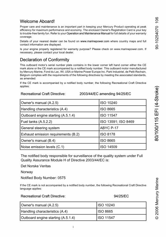
Welcome Aboard!Proper care and maintenance is an important part in keeping your Mercury Product operating at peakefficiency for maximum performance and economy. The enclosed Owner's Registration Card is your keyto trouble-free family fun. Refer to your Operation and Maintenance Manual for full details of your warrantycoverage.Details of your nearest dealer can be found on www.marinepower.com where country maps and fullcontact information are displayed.Is your engine properly registered for warranty purpose? Please check on www.marinepower.com. Ifnecessary, please contact your local dealer.
Declaration of ConformityThis outboard motor’s serial number plate contains in the lower corner left hand corner either the CEmark alone or the CE mark accompanied by a notified body number. This outboard motor manufacturedby Mercury Marine, Fond du Lac, WI, USA or Marine Power Europe Inc. Park Industriel, de Petit-Rechain,Belgium complies with the requirements of the following directives by meeting the associated standards,as amended:If the CE mark is accompanied by a notified body number, the following Recreational Craft Directiveapplies:
Recreational Craft Directive: 2003/44/EC amending 94/25/EC
Owner's manual (A.2.5) ISO 10240
Handling characteristics (A.4) ISO 8665
Outboard engine starting (A.5.1.4) ISO 11547
Fuel tanks (A.5.2.2) ISO 13591; ISO 8469
General steering system ABYC P-17
Exhaust emission requirements (B.2) ISO 8178
Owner's manual (B.4) ISO 8665
Noise emission levels (C.1) ISO 14509
The notified body responsible for surveillance of the quality system under FullQuality Assurance Module H of Directive 2003/44/EC is:Det Norske VeritasNorwayNotified Body Number: 0575
If the CE mark is not accompanied by a notified body number, the following Recreational Craft Directivelanguage applies:
Recreational Craft Directive: 94/25/EC
Owner's manual (A.2.5) ISO 10240
Handling characteristics (A.4) ISO 8665
Outboard engine starting (A.5.1.4) ISO 11547 © 2
006
Mer
cury
Mar
ine
80/1
00/1
15 E
FI (4
-Stro
ke)
90-1
0254
070
106
ii
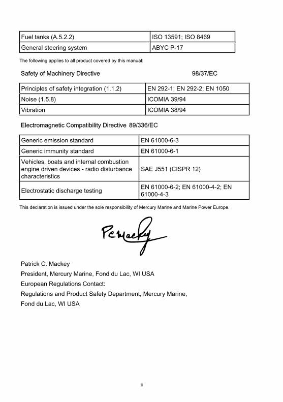
Fuel tanks (A.5.2.2) ISO 13591; ISO 8469
General steering system ABYC P-17
The following applies to all product covered by this manual:
Safety of Machinery Directive 98/37/EC
Principles of safety integration (1.1.2) EN 292-1; EN 292-2; EN 1050
Noise (1.5.8) ICOMIA 39/94
Vibration ICOMIA 38/94
Electromagnetic Compatibility Directive 89/336/EC
Generic emission standard EN 61000-6-3
Generic immunity standard EN 61000-6-1
Vehicles, boats and internal combustionengine driven devices - radio disturbancecharacteristics
SAE J551 (CISPR 12)
Electrostatic discharge testing EN 61000-6-2; EN 61000-4-2; EN61000-4-3
This declaration is issued under the sole responsibility of Mercury Marine and Marine Power Europe.
Patrick C. MackeyPresident, Mercury Marine, Fond du Lac, WI USAEuropean Regulations Contact:Regulations and Product Safety Department, Mercury Marine,Fond du Lac, WI USA
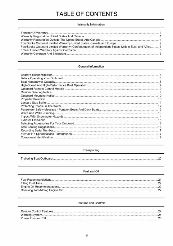
TABLE OF CONTENTS
iii
Warranty Information
Transfer Of Warranty..........................................................................................................................................1Warranty Registration United States And Canada.............................................................................................. 1Warranty Registration Outside The United States And Canada......................................................................... 1FourStroke Outboard Limited Warranty United States, Canada and Europe..................................................... 2FourStroke Outboard Limited Warranty (Confederation of Independent States, Middle-East, and Africa.......... 33 Year Limited Warranty Against Corrosion........................................................................................................ 5Warranty Coverage And Exclusions................................................................................................................... 6
General Information
Boater's Responsibilities.....................................................................................................................................8Before Operating Your Outboard........................................................................................................................ 8Boat Horsepower Capacity.................................................................................................................................8High-Speed And High-Performance Boat Operation.......................................................................................... 9Outboard Remote Control Models .....................................................................................................................9Remote Steering Notice......................................................................................................................................9Outboard Mounting Notice................................................................................................................................10Propeller Selection............................................................................................................................................10Lanyard Stop Switch.........................................................................................................................................11Protecting People In The Water........................................................................................................................ 12Passenger Safety Message - Pontoon Boats And Deck Boats........................................................................ 13Wave And Wake Jumping................................................................................................................................. 13Impact With Underwater Hazards.....................................................................................................................14Exhaust Emissions............................................................................................................................................ 15Selecting Accessories For Your Outboard........................................................................................................16Safe Boating Suggestions................................................................................................................................. 16Recording Serial Number.................................................................................................................................. 1780/100/115 Specifications - International..........................................................................................................17Component Identification..................................................................................................................................19
Transporting
Trailering Boat/Outboard................................................................................................................................... 20
Fuel and Oil
Fuel Recommendations....................................................................................................................................21Filling Fuel Tank................................................................................................................................................ 22Engine Oil Recommendations..........................................................................................................................22Checking and Adding Engine Oil......................................................................................................................22
Features and Controls
Remote Control Features.................................................................................................................................. 24Warning System................................................................................................................................................ 24Power Trim and Tilt...........................................................................................................................................26
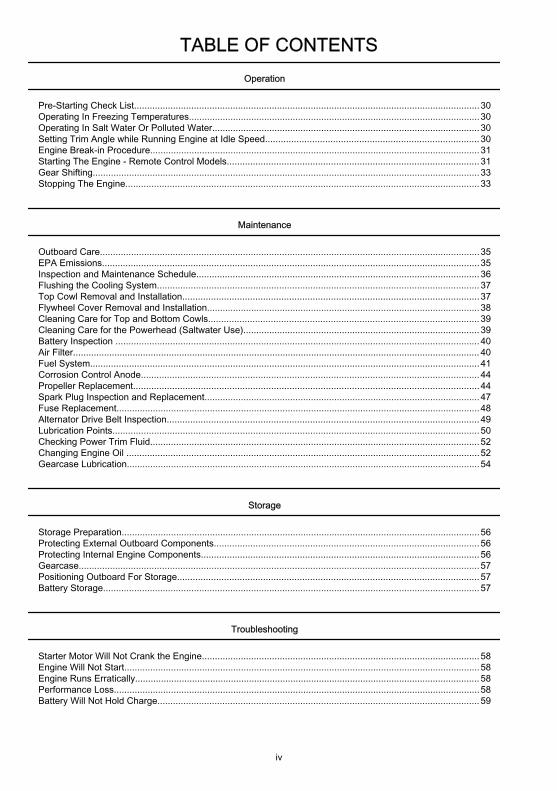
TABLE OF CONTENTS
iv
Operation
Pre-Starting Check List.....................................................................................................................................30Operating In Freezing Temperatures................................................................................................................30Operating In Salt Water Or Polluted Water.......................................................................................................30Setting Trim Angle while Running Engine at Idle Speed.................................................................................. 30Engine Break-in Procedure...............................................................................................................................31Starting The Engine - Remote Control Models................................................................................................. 31Gear Shifting.....................................................................................................................................................33Stopping The Engine........................................................................................................................................ 33
Maintenance
Outboard Care..................................................................................................................................................35EPA Emissions.................................................................................................................................................35Inspection and Maintenance Schedule.............................................................................................................36Flushing the Cooling System............................................................................................................................ 37Top Cowl Removal and Installation..................................................................................................................37Flywheel Cover Removal and Installation.........................................................................................................38Cleaning Care for Top and Bottom Cowls........................................................................................................ 39Cleaning Care for the Powerhead (Saltwater Use)........................................................................................... 39Battery Inspection ............................................................................................................................................40Air Filter............................................................................................................................................................. 40Fuel System......................................................................................................................................................41Corrosion Control Anode..................................................................................................................................44Propeller Replacement.....................................................................................................................................44Spark Plug Inspection and Replacement..........................................................................................................47Fuse Replacement............................................................................................................................................48Alternator Drive Belt Inspection........................................................................................................................49Lubrication Points.............................................................................................................................................50Checking Power Trim Fluid...............................................................................................................................52Changing Engine Oil ........................................................................................................................................52Gearcase Lubrication........................................................................................................................................54
Storage
Storage Preparation..........................................................................................................................................56Protecting External Outboard Components......................................................................................................56Protecting Internal Engine Components...........................................................................................................56Gearcase..........................................................................................................................................................57Positioning Outboard For Storage.................................................................................................................... 57Battery Storage.................................................................................................................................................57
Troubleshooting
Starter Motor Will Not Crank the Engine...........................................................................................................58Engine Will Not Start.........................................................................................................................................58Engine Runs Erratically..................................................................................................................................... 58Performance Loss.............................................................................................................................................58Battery Will Not Hold Charge............................................................................................................................ 59
TABLE OF CONTENTS
v
Owner Service Assistance
Local Repair Service.........................................................................................................................................60Service Away From Home................................................................................................................................ 60Parts And Accessories Inquiries.......................................................................................................................60Service Assistance............................................................................................................................................ 60Mercury Marine Service Offices........................................................................................................................ 60
Outboard Installation
Important Information........................................................................................................................................62Boat Horsepower Capacity............................................................................................................................... 62Start in Gear Protection.................................................................................................................................... 62Selecting Accessories For Your Outboard........................................................................................................62Fuel Tanks........................................................................................................................................................63Filling the Fuel System...................................................................................................................................... 63Installation Specifications.................................................................................................................................. 63Lifting Outboard................................................................................................................................................ 63Steering Cable - Starboard Side Routed Cable................................................................................................ 64Steering Link Rod Fasteners............................................................................................................................ 65Determining Recommended Outboard Mounting Height.................................................................................. 67Drilling Outboard Mounting Holes.....................................................................................................................68Fastening the Outboard to the Transom........................................................................................................... 69Electrical, Fuel Hose, and Control Cables........................................................................................................ 71Trim In Pin......................................................................................................................................................... 80

vi

WARRANTY INFORMATION
1
Transfer Of WarrantyThe limited warranty is transferable to a subsequent purchaser, but only for the remainder of the unused portionof the limited warranty. This will not apply to products used for commercial applications.To transfer the warranty to the subsequent owner, send or fax a copy of the bill of sale or purchase agreement,new owner’s name, address and engine serial number to Mercury Marine’s warranty registration department. Inthe United States and Canada, mail to:Mercury MarineAttn: Warranty Registration DepartmentW6250 W. Pioneer RoadP.O. Box 1939Fond du Lac, WI 54936-1939920-929-5054Fax 920-929-5893Upon processing the transfer of warranty, Mercury Marine will send registration verification to the new owner ofthe product by mail.There is no charge for this service.For products purchased outside the United States and Canada, contact the distributor in your country, or theMarine Power Service Center closest to you.
Warranty Registration United States And Canada1. You may change your address at any time, including at time of warranty claim, by calling Mercury Marine
or sending a letter or fax with your name, old address, new address, and engine serial number to MercuryMarine’s warranty registration department. Your dealer can also process this change of information.Mercury MarineAttn: Warranty Registration DepartmentW6250 Pioneer RoadP.O. Box 1939Fond du Lac, WI 54936-1939920-929-5054Fax 920-929-5893
NOTE: Registration lists must be maintained by Mercury Marine and any dealer on marine products sold in theUnited States, should a safety recall notification under the Federal Safety Act be required.2. To be eligible for warranty coverage, the product must be registered with Mercury Marine. At the time of
sale, the dealer should complete the warranty registration and immediately submit it to Mercury Marinevia MercNET, E-mail, or mail. Upon receipt of this warranty registration, Mercury Marine will record theregistration.
3. Upon processing the warranty registration, Mercury Marine will send registration verification by mail tothe purchaser of the product. If this registration verification is not received within 30 days, please contactyour selling dealer immediately. Warranty coverage is not effective until your product is registered withMercury Marine.
Warranty Registration Outside The United States And Canada1. It is important that your selling dealer fills out the Warranty Registration Card completely and mails it to
the distributor or Marine Power Service Center responsible for administering the warranty registration/claim program for your area.
2. The Warranty Registration Card identifies your name and address, product model and serial numbers,date of sale, type of use and the selling distributor's/dealer's code number, name and address. Thedistributor/dealer also certifies that you are the original purchaser and user of the product.
3. A copy of the Warranty Registration Card, designated as the Purchaser's Copy, MUST be given to youimmediately after the card has been completely filled out by the selling distributor/dealer. This cardrepresents your factory registration identification, and should be retained by you for future use whenrequired. Should you ever require warranty service on this product, your dealer may ask you for theWarranty Registration Card to verify date of purchase and to use the information on the card to preparethe warranty claim forms.
WARRANTY INFORMATION
2
4. In some countries, the Marine Power Service Center will issue you a permanent (plastic) WarrantyRegistration Card within 30 days after receiving the Factory Copy of the Warranty Registration Card fromyour distributor/dealer. If you receive a plastic Warranty Registration Card, you may discard thePurchaser's Copy that you received from the distributor/dealer when you purchased the product. Askyour distributor/dealer if this plastic card program applies to you.
IMPORTANT: Registration lists must be maintained by the factory and dealer in some countries by law. It isour desire to have ALL products registered at the factory should it ever be necessary to contact you. Make sureyour dealer/distributor fills out the warranty registration card immediately and sends the factory copy to theMarine Power International Service Center for your area.5. For further information concerning the Warranty Registration Card and its relationship to Warranty Claim
processing, refer to the International Warranty.
FourStroke Outboard Limited Warranty United States, Canada andEuropeOutside the United States, Canada and Europe - check with local distributor.WHAT IS COVERED: Mercury Marine warrants its new products to be free of defects in material andworkmanship during the period described below.DURATION OF COVERAGE: This Limited Warranty provides coverage for two (2) years from the date theproduct is first sold to a recreational use retail purchaser, or the date on which the product is first put into service,whichever occurs first. Commercial users of these products receive warranty coverage of one (1) year from thedate of first retail sale, or one (1) year from the date in which the product was first put into service, whicheveroccurs first. Commercial use is defined as any work or employment related use of the product, or any use of theproduct which generates income, for any part of the warranty period, even if the product is only occasionallyused for such purposes. The repair or replacement of parts, or the performance of service under this warranty,does not extend the life of this warranty beyond its original expiration date. Unexpired warranty coverage canbe transferred from one recreational use customer to a subsequent recreational use customer upon proper re–registration of the product. Unexpired warrant coverage cannot be transferred either to or from a commercialuse customer.CONDITIONS THAT MUST BE MET IN ORDER TO OBTAIN WARRANTY COVERAGE: Warranty coverage isavailable only to retail customers that purchase from a Dealer authorized by Mercury Marine to distribute theproduct in the country in which the sale occurred, and then only after the Mercury Marine specified pre–deliveryinspection process is completed and documented. Warranty coverage becomes available upon properregistration of the product by the authorized dealer. Routine maintenance outlined in the Operation andMaintenance Manual must be timely performed in order to maintain warranty coverage. Mercury Marine reservesthe right to make future warranty coverage contingent on proof of proper maintenance.WHAT MERCURY WILL DO: Mercury’s sole and exclusive obligation under this warranty is limited to, at ouroption, repairing a defective part, replacing such part or parts with new or Mercury Marine certifiedremanufactured parts, or refunding the purchase price of the Mercury product. Mercury reserves the right toimprove or modify products from time to time without assuming an obligation to modify products previouslymanufactured.HOW TO OBTAIN WARRANTY COVERAGE: The customer must provide Mercury with a reasonableopportunity to repair, and reasonable access to the product for warranty service. Warranty claims shall be madeby delivering the product for inspection to a Mercury dealer authorized to service the product. If purchaser cannotdeliver the product to such a dealer, written notice must be given to Mercury. We will then arrange for theinspection and any covered repair. Purchaser in that case shall pay for all related transportation charges and/or travel time. If the service provided is not covered by this warranty, purchaser shall pay for all related laborand material, and any other expenses associated with that service. Purchaser shall not, unless requested byMercury, ship the product or parts of the product directly to Mercury. Proof of registered ownership must bepresented to the dealer at the time warranty service is requested in order to obtain coverage.

WARRANTY INFORMATION
3
WHAT IS NOT COVERED: This limited warranty does not cover routine maintenance items, tune ups,adjustments, normal wear and tear, damage caused by abuse, abnormal use, use of a propeller or gear ratiothat does not allow the engine to run in its recommended wide open throttle RPM range (see the Operation andMaintenance Manual), operation of the product in a manner inconsistent with the recommended operation/dutycycle section of the Operation and Maintenance Manual, neglect, accident, submersion, improper installation(proper installation specifications and techniques are set forth in the installation instructions for the product),improper service, use of an accessory or part not manufactured or sold by us, jet pump impellers and liners,operation with fuels, oils or lubricants which are not suitable for use with the product (see the Operation andMaintenance Manual), alteration or removal of parts, or water entering the engine through the fuel intake, airintake or exhaust system, or damage to the product from insufficient cooling water caused by blockage of thecooling system by a foreign body, running the engine out of water, mounting the engine too high on the transom,or running the boat with the engine trimmed out too far.. Use of the product for racing or other competitive activity,or operating with a racing type lower unit, at any point, even by a prior owner of the product, voids the warranty.Expenses related to haul out, launch, towing, storage, telephone, rental, inconvenience, slip fees, insurancecoverage, loan payments, loss of time, loss of income, or any other type of incidental or consequential damagesare not covered by this warranty. Also, expenses associated with the removal and/or replacement of boatpartitions or material caused by boat design for access to the product are not covered by this warranty.No individual or entity, including Mercury Marine authorized dealers, has been given authority by Mercury Marineto make any affirmation, representation or warranty regarding the product, other than those contained in thislimited warranty, and if made, shall not be enforceable against Mercury Marine.For additional information regarding events and circumstances covered by this warranty, and those that are not,see the Warranty Coverage section of the Operation and Maintenance Manual, incorporated by reference intothis warranty.
DISCLAIMERS AND LIMITATIONS:
THE IMPLIED WARRANTIES OF MERCHANTABILITY AND FITNESS FOR APARTICULAR PURPOSE ARE EXPRESSLY DISCLAIMED. TO THE EXTENT THATTHEY CANNOT BE DISCLAIMED, THE IMPLIED WARRANTIES ARE LIMITED INDURATION TO THE LIFE OF THE EXPRESS WARRANTY. INCIDENTAL ANDCONSEQUENTIAL DAMAGES ARE EXCLUDED FROM COVERAGE UNDER THISWARRANTY. SOME STATES/COUNTRIES DO NOT ALLOW FOR THEDISCLAIMERS, LIMITATIONS AND EXCLUSIONS IDENTIFIED ABOVE, AS ARESULT, THEY MAY NOT APPLY TO YOU. THIS WARRANTY GIVES YOUSPECIFIC LEGAL RIGHTS, AND YOU MAY ALSO HAVE OTHER LEGAL RIGHTSWHICH VARY FROM STATE TO STATE AND COUNTRY TO COUNTRY.
FourStroke Outboard Limited Warranty (Confederation of IndependentStates, Middle-East, and AfricaWHAT IS COVERED: Mercury Marine warrants its new Outboard and Jet Products to be free of defects inmaterial and workmanship during the period described below.DURATION OF COVERAGE: This Limited Warranty provides coverage for one (1) year from the date the productis first sold to a recreational use retail purchaser, or the date on which the product is first put into service,whichever occurs first. Commercial users of these products receive warranty coverage of one (1) years from thedate of first retail sale, or one (1) year from the date on which the product was first put into service, whicheveroccurs first. Commercial use is defined as any work or employment related use of the product, or any use of theproduct which generates income, for any part of the warranty period, even if the product is only occasionallyused for such purposes. The repair or replacement of parts, or the performance of service under this warranty,does not extend the life of this warranty beyond its original expiration date. Unexpired warranty coverage canbe transferred from one recreational use customer to a subsequent recreational use customer upon proper re-registration of the product. Unexpired warranty coverage cannot be transferred either to or from a commercialuse customer.
WARRANTY INFORMATION
4
CONDITIONS THAT MUST BE MET IN ORDER TO OBTAIN WARRANTY COVERAGE: Warranty coverage isavailable only to retail customers that purchase from a Dealer authorized by Mercury Marine to distribute theproduct in the country in which the sale occurred, and then only after the Mercury Marine specified pre–deliveryinspection process is completed and documented. Warranty coverage becomes available upon properregistration of the product by the authorized dealer. Routine maintenance outlined in the Operation andMaintenance Manual must be timely performed in order to maintain warranty coverage. Mercury Marine reservesthe right to make warranty coverage contingent on proof of proper maintenance.WHAT MERCURY WILL DO: Mercury’s sole and exclusive obligation under this warranty is limited to, at ouroption, repairing a defective part, replacing such part or parts with new or Mercury Marine certified re–manufactured parts, or refunding the purchase price of the Mercury product. Mercury reserves the right toimprove or modify products from time to time without assuming an obligation to modify products previouslymanufactured.HOW TO OBTAIN WARRANTY COVERAGE: The customer must provide Mercury with a reasonableopportunity to repair, and reasonable access to the product for warranty service. Warranty claims shall be madeby delivering the product for inspection to a Mercury dealer authorized to service the product. If purchaser cannotdeliver the product to such a dealer, written notice must be given to Mercury. We will then arrange for theinspection and any covered repair. Purchaser in that case shall pay for all related transportation charges and/or travel time. If the service provided is not covered by this warranty, purchaser shall pay for all related laborandmaterial, and any other expenses associated with that service. Purchaser shall not, unless requested by Mercury,ship the product or parts of the product directly to Mercury. Proof of registered ownership must be presented tothe dealer at the time warranty service is requested in order to obtain coverage.WHAT IS NOT COVERED: This limited warranty does not cover routine maintenance items, tune ups,adjustments, normal wear and tear, damage caused by abuse, abnormal use, use of a propeller or gear ratiothat does not allow the engine to run in its recommended wide open throttle RPM range (see the Operation andMaintenance Manual), operation of the product in a manner inconsistent with the recommended operation/dutycycle section of the Operation and Maintenance Manual, neglect, accident, submersion, improper installation(proper installation specifications and techniques are set forth in the installation instructions for the product),improper service, use of an accessory or part not manufactured or sold by us, jet pump impellers and liners,operation with fuels, oils or lubricants which are not suitable for use with the product (see the Operation andMaintenance Manual), alteration or removal of parts, or water entering the engine through the fuel intake, airintake or exhaust system, or damage to the product from insufficient cooling water caused by blockage of thecooling system by foreign body, running the engine out of water, mounting the engine too high on the transom,or running the boat with the engine trimmed out too far.Use of the product for racing or other competitive activity, or operating with a racing type lower unit, at any point,even by a prior owner of the product, voids the warranty.Expenses related to haul out, launch, towing, storage, telephone, rental, inconvenience, slip fees, insurancecoverage, loan payments, loss of time, loss of income, or any other type of incidental or consequential damagesare not coveredby this warranty. Also, expenses associated with the removal and/or replacement of boatpartitions or material caused by boat design for access to the product are not covered by this warranty.No individual or entity, including Mercury Marine authorized dealers, has been given authority by Mercury Marineto make any affirmation, representation or warranty regarding the product, other than those contained in thislimited warranty, and if made, shall not be enforceable against Mercury Marine.For additional information regarding events and circumstances covered by this warranty, and those that are not,see the Warranty Coverage section of the Operation and Maintenance Manual, incorporated by reference intothis warranty.

WARRANTY INFORMATION
5
DISCLAIMERS AND LIMITATIONS:
THE IMPLIED WARRANTIES OF MERCHANTABILITY AND FITNESS FOR APARTICULAR PURPOSE ARE EXPRESSLY DISCLAIMED. TO THE EXTENT THATTHEY CANNOT BE DISCLAIMED, THE IMPLIED WARRANTIES ARE LIMITED INDURATION TO THE LIFE OF THE EXPRESS WARRANTY. INCIDENTAL ANDCONSEQUENTIAL DAMAGES ARE EXCLUDED FROM COVERAGE UNDER THISWARRANTY. SOME STATES/COUNTRIES DO NOT ALLOW FOR THEDISCLAIMERS, LIMITATIONS AND EXCLUSIONS IDENTIFIED ABOVE, AS ARESULT, THEY MAY NOT APPLY TO YOU. THIS WARRANTY GIVES YOUSPECIFIC LEGAL RIGHTS, AND YOU MAY ALSO HAVE OTHER LEGAL RIGHTSWHICH VARY FROM STATE TO STATE AND COUNTRY TO COUNTRY.
3 Year Limited Warranty Against CorrosionWHAT IS COVERED: Mercury Marine warrants that each new Mercury, Mariner, Mercury Racing, Sport Jet,M2 Jet Drive, Tracker by Mercury Marine Outboard, Mercury MerCruiser Inboard or Sterndrive Engine (Product)will not be rendered inoperative as a direct result of corrosion for the period of time described below.DURATION OF COVERAGE: This limited corrosion warranty provides coverage for three (3) years from eitherthe date the product is first sold, or the date on which the product is first put into service, whichever occurs first.The repair or replacement of parts, or the performance of service under this warranty does not extend the lifeof this warranty beyond its original expiration date. Unexpired warranty coverage can be transferred tosubsequent (non-commercial use) purchaser upon proper re-registration of the product.CONDITIONS THAT MUST BE MET IN ORDER TO OBTAIN WARRANTY COVERAGE: Warranty coverage isavailable only to retail customers that purchase from a Dealer authorized by Mercury Marine to distribute theproduct in the country in which the sale occurred, and then only after the Mercury Marine specified pre-deliveryinspection process is completed and documented. Warranty coverage becomes available upon properregistration of the product by the authorized dealer. Corrosion prevention devices specified in the Operation andMaintenance Manual must be in use on the boat, and routine maintenance outlined in the Operation andMaintenance Manual must be timely performed (including without limitation the replacement of sacrificial anodes,use of specified lubricants, and touch-up of nicks and scratches) in order to maintain warranty coverage. MercuryMarine reserves the right to make warranty coverage contingent upon proof of proper maintenance.WHAT MERCURY WILL DO: Mercury's sole and exclusive obligation under this warranty is limited to, at ouroption, repairing a corroded part, replacing such part or parts with new or Mercury Marine certified re-manufactured parts, or refunding the purchase price of the Mercury product. Mercury reserves the right toimprove or modify products from time to time without assuming an obligation to modify products previouslymanufactured.HOW TO OBTAIN WARRANTY COVERAGE: The customer must provide Mercury with a reasonableopportunity to repair, and reasonable access to the product for warranty service. Warranty claims shall be madeby delivering the product for inspection to a Mercury dealer authorized to service the product. If purchaser cannotdeliver the product to such a dealer, written notice must be given to Mercury. We will then arrange for theinspection and any covered repair. Purchaser in that case shall pay for all related transportation charges and/or travel time. If the service provided is not covered by this warranty, purchaser shall pay for all related laborand material, and any other expenses associated with that service. Purchaser shall not, unless requested byMercury, ship the product or parts of the product directly to Mercury. Proof of registered ownership must bepresented to the dealer at the time warranty service is requested in order to obtain coverage.WHAT IS NOT COVERED: This limited warranty does not cover electrical system corrosion; corrosion resultingfrom damage, corrosion which causes purely cosmetic damage, abuse or improper service; corrosion toaccessories, instruments, steering systems; corrosion to factory installed jet drive unit; damage due to marinegrowth; product sold with less than a one year limited Product warranty; replacement parts (parts purchased bycustomer); products used in a commercial application. Commercial use is defined as any work or employmentrelated use of the product, or any use of the product which generates income, for any part of the warranty period,even if the product is only occasionally used for such purposes.
WARRANTY INFORMATION
6
Corrosion damage caused by stray electrical currents (on-shore power connections, nearby boats, submergedmetal) is not covered by this corrosion warranty and should be protected against by the use of a corrosionprotection system, such as the Mercury Precision Parts or Quicksilver MerCathode system and/or GalvanicIsolator. Corrosion damage caused by improper application of copper base anti-fouling paints is also not coveredby this limited warranty. If anti-fouling protection is required, Tri-Butyl-Tin-Adipate (TBTA) base anti-fouling paintsare recommended on Outboard and MerCruiser boating applications. In areas where TBTA base paints areprohibited by law, copper base paints can be used on the hull and transom. Do not apply paint to the outboardor MerCruiser product. In addition, care must be taken to avoid an electrical interconnection between thewarranted product and the paint. For MerCruiser product, an unpainted gap of at least 38 mm (1.5 in.) shouldbe left around the transom assembly. Refer to the Operation and Maintenance Manual for additional details.For additional information regarding events and circumstances covered by this warranty, and those that are not,see the Warranty Coverage section of the Operation and Maintenance Manual, incorporated by reference intothis warranty.
DISCLAIMERS AND LIMITATIONS:
THE IMPLIED WARRANTIES OF MERCHANTABILITY AND FITNESS FOR APARTICULAR PURPOSE ARE EXPRESSLY DISCLAIMED. TO THE EXTENT THATTHEY CANNOT BE DISCLAIMED, THE IMPLIED WARRANTIES ARE LIMITED INDURATION TO THE LIFE OF THE EXPRESS WARRANTY. INCIDENTAL ANDCONSEQUENTIAL DAMAGES ARE EXCLUDED FROM COVERAGE UNDER THISWARRANTY. SOME STATES/COUNTRIES DO NOT ALLOW FOR THEDISCLAIMERS, LIMITATIONS AND EXCLUSIONS IDENTIFIED ABOVE, AS ARESULT, THEY MAY NOT APPLY TO YOU. THIS WARRANTY GIVES YOUSPECIFIC LEGAL RIGHTS, AND YOU MAY ALSO HAVE OTHER LEGAL RIGHTSWHICH VARY FROM STATE TO STATE AND COUNTRY TO COUNTRY.
Warranty Coverage And ExclusionsThe purpose of this section is to help eliminate some of the more common misunderstandings regarding warrantycoverage. The following information explains some of the types of services that are not covered by warranty.The provisions set forth following have been incorporated by reference into the Three Year Limited WarrantyAgainst Corrosion Failure, the International Limited Outboard Warranty, and the United States and CanadaLimited Outboard Warranty.Keep in mind that warranty covers repairs that are needed within the warranty period because of defects inmaterial and workmanship. Installation errors, accidents, normal wear, and a variety of other causes that affectthe product are not covered.Warranty is limited to defects in material or workmanship, but only when the consumer sale is made in the countryto which distribution is authorized by us.Should you have any questions concerning warranty coverage, contact your authorized dealer. They will bepleased to answer any questions that you may have.
GENERAL EXCLUSIONS FROM WARRANTY1. Minor adjustments and tune-ups, including checking, cleaning or adjusting spark plugs, ignition
components, carburetor settings, filters, belts, controls, and checking lubrication made in connection withnormal services.
2. Factory installed jet drive units - Specific parts excluded from the warranty are: The jet drive impeller andjet drive liner damaged by impact or wear, and water damaged drive shaft bearings as a result of impropermaintenance.
3. Damage caused by neglect, lack of maintenance, accident, abnormal operation or improper installationor service.
4. Haul out, launch, towing charges, removal and/or replacement of boat partitions or material because ofboat design for necessary access to the product, all related transportation charges and/or travel time,etc. Reasonable access must be provided to the product for warranty service. Customer must deliverproduct to an authorized dealer.
WARRANTY INFORMATION
7
5. Additional service work requested by customer other than that necessary to satisfy the warrantyobligation.
6. Labor performed by other than an authorized dealer may be covered only under following circumstances:When performed on emergency basis (providing there are no authorized dealers in the area who canperform the work required or have no facilities to haul out, etc., and prior factory approval has been givento have the work performed at this facility).
7. All incidental and/or consequential damages (storage charges, telephone or rental charges of any type,inconvenience or loss of time or income) are the owner's responsibility.
8. Use of other than Mercury Precision or Quicksilver parts when making warranty repairs.9. Oils, lubricants or fluids changed as a matter of normal maintenance is customer's responsibility unless
loss or contamination of same is caused by product failure that would be eligible for warrantyconsideration.
10. Participating in or preparing for racing or other competitive activity or operating with a racing type lowerunit.
11. Engine noise does not necessarily indicate a serious engine problem. If diagnosis indicates a seriousinternal engine condition which could result in a failure, condition responsible for noise should becorrected under the warranty.
12. Lower unit and/or propeller damage caused by striking a submerged object is considered a marinehazard.
13. Water entering engine through the fuel intake, air intake or exhaust system or submersion.14. Failure of any parts caused by lack of cooling water, which results from starting motor out of water, foreign
material blocking inlet holes, motor being mounted too high or trimmed too far out.15. Use of fuels and lubricants which are not suitable for use with or on the product. Refer to the
Maintenance section.16. Our limited warranty does not apply to any damage to our products caused by the installation or use of
parts and accessories which are not manufactured or sold by us. Failures which are not related to theuse of those parts or accessories are covered under warranty if they otherwise meet the terms of thelimited warranty for that product.

GENERAL INFORMATION
8
Boater's ResponsibilitiesThe operator (driver) is responsible for the correct and safe operation of the boat and safety of its occupantsand general public. It is strongly recommended that each operator (driver) read and understand this entiremanual before operating the outboard.Be sure at least one additional person on board is instructed in the basics of starting and operating the outboardand boat handling in case the driver is unable to operate the boat.
Before Operating Your OutboardRead this manual carefully. Learn how to operate your outboard properly. If you have any questions, contactyour dealer.Safety and operating information that is practiced, along with using good common sense, can help preventpersonal injury and product damage.This manual as well as safety labels posted on the outboard use the following safety alerts to draw your attentionto special safety instructions that should be followed.
! DANGERDANGER—indicates an imminently hazardous situation that, if not avoided, will result in death or seriousinjury.
! WARNINGWARNING—indicates a potentially hazardous situation that, if not avoided, could result in death or seriousinjury.
! CAUTIONCAUTION—indicates a potentially hazardous situation that, if not avoided, may result in minor or moderateinjury or property damage. It may also be used to alert against unsafe practices.
Boat Horsepower Capacity
! WARNINGUsing an outboard that exceeds the maximum horsepower limit of a boat can: 1) cause loss of boat control2) place too much weight at the transom altering the designed flotation characteristics of the boat or 3) causethe boat to break apart particularly around the transom area. Overpowering a boat can result in serious injury,death or boat damage.
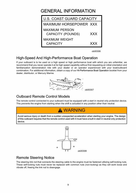
Do not overpower or overload your boat. Most boats will carry a required capacity plate indicating the maximumacceptable power and load as determined by the manufacturer following certain federal guidelines. If in doubt,contact your dealer or the boat manufacturer.
GENERAL INFORMATION
9
U.S. COAST GUARD CAPACITYMAXIMUM HORSEPOWER XXXMAXIMUM PERSON CAPACITY (POUNDS) XXXMAXIMUM WEIGHT CAPACITY XXX
ob00306
High-Speed And High-Performance Boat OperationIf your outboard is to be used on a high speed or high performance boat with which you are unfamiliar, werecommend that you never operate it at its high speed capability without first requesting an initial orientation andfamiliarization demonstration ride with your dealer or an operator experienced with your boat/outboardcombination. For additional information, obtain a copy of our Hi-Performance Boat Operation booklet from yourdealer, distributor, or Mercury Marine.
ob00307
Outboard Remote Control ModelsThe remote control connected to your outboard must be equipped with a start in neutral only protection device.This prevents the engine from starting when the shift is actuated in any position other than neutral.
! WARNINGAvoid serious injury or death from a sudden unexpected acceleration when starting your engine. The designof this outboard requires that the remote control used with it must have a built in start in neutral only protectiondevice.
ob00308
Remote Steering NoticeThe steering link rod that connects the steering cable to the engine must be fastened utilizing self-locking nuts.These self-locking nuts must never be replaced with common nuts (non-locking) as they will work loose andvibrate off, freeing the link rod to disengage.
GENERAL INFORMATION
10
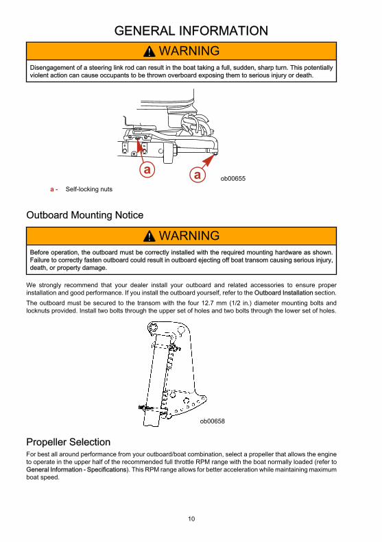
! WARNINGDisengagement of a steering link rod can result in the boat taking a full, sudden, sharp turn. This potentiallyviolent action can cause occupants to be thrown overboard exposing them to serious injury or death.
ob00655a a
a - Self-locking nuts
Outboard Mounting Notice
! WARNINGBefore operation, the outboard must be correctly installed with the required mounting hardware as shown.Failure to correctly fasten outboard could result in outboard ejecting off boat transom causing serious injury,death, or property damage.
We strongly recommend that your dealer install your outboard and related accessories to ensure properinstallation and good performance. If you install the outboard yourself, refer to the Outboard Installation section.The outboard must be secured to the transom with the four 12.7 mm (1/2 in.) diameter mounting bolts andlocknuts provided. Install two bolts through the upper set of holes and two bolts through the lower set of holes.
ob00658
Propeller SelectionFor best all around performance from your outboard/boat combination, select a propeller that allows the engineto operate in the upper half of the recommended full throttle RPM range with the boat normally loaded (refer toGeneral Information - Specifications). This RPM range allows for better acceleration while maintaining maximumboat speed.

GENERAL INFORMATION
11
22551
If changing conditions cause the RPM to drop below the recommended range, such as warmer, more humidweather, operation at higher elevations, increased boat load, or a dirty boat bottom/gearcase, a propeller changeor cleaning may be required to maintain performance and ensure the outboards durability.Check full-throttle RPM, using an accurate tachometer, with the engine trimmed out to a balanced-steeringcondition (steering effort equal in both directions) without causing the propeller to break loose.
Lanyard Stop SwitchThe purpose of a lanyard stop switch is to turn off the engine when the operator moves far enough away fromthe operator's position (as in accidental ejection from the operator's position) to activate the switch. Tiller handleoutboards and some remote control units are equipped with a lanyard stop switch. A lanyard stop switch can beinstalled as an accessory - generally on the dashboard or side adjacent to the operator's position.The lanyard is a cord usually between 122 and 152 cm (4 and 5 feet) in length when stretched out, with anelement on one end made to be inserted into the switch and a snap on the other end for attaching to the operator.The lanyard is coiled to make its at-rest condition as short as possible to minimize the likelihood of lanyardentanglement with nearby objects. Its stretched-out length is made to minimize the likelihood of accidentalactivation should the operator choose to move around in an area close to the normal operator's position. If it isdesired to have a shorter lanyard, wrap the lanyard around the operator's wrist or leg, or tie a knot in the lanyard.
21629
a b
a - Lanyard cord b - Lanyard stop switch
Read the following Safety Information before proceeding.Important Safety Information: The purpose of a lanyard stop switch is to stop the engine when the operatormoves far enough away from the operator's position to activate the switch. This would occur if the operatoraccidentally falls overboard or moves within the boat a sufficient distance from the operator's position. Fallingoverboard and accidental ejections are more likely to occur in certain types of boats such as low sided inflatables,bass boats, high performance boats, and light, sensitive handling fishing boats operated by a hand tiller. Fallingoverboard and accidental ejections are also likely to occur as a result of poor operating practices such as sittingon the back of the seat or gunwale at planing speeds, standing at planing speeds, sitting on elevated fishingboat decks, operating at planing speeds in shallow or obstacle infested waters, releasing your grip on a steeringwheel or tiller handle that is pulling in one direction, drinking alcohol or consuming drugs, or daring high speedboat maneuvers.While activation of the lanyard stop switch will stop the engine immediately, a boat will continue to coast for somedistance depending upon the velocity and degree of any turn at shut down. However, the boat will not completea full circle. While the boat is coasting, it can cause injury to anyone in the boat's path as seriously as the boatwould when under power.

GENERAL INFORMATION
12
We strongly recommend that other occupants be instructed on proper starting and operating procedures shouldthey be required to operate the engine in an emergency (e.g. if the operator is accidentally ejected).
! WARNINGShould the operator fall out of the boat, the possibility of serious injury or death from being run over by theboat can be greatly reduced by stopping the engine immediately. Always properly connect both ends of thestop switch lanyard to the stop switch and the operator.
! WARNINGAvoid serious injury or death from deceleration forces resulting from accidental or unintended stop switchactivation. The boat operator should never leave the operator's station without first disconnecting the stopswitch lanyard from the operator.
Accidental or unintended activation of the switch during normal operation is also a possibility. This could causeany, or all, of the following potentially hazardous situations:• Occupants could be thrown forward due to unexpected loss of forward motion - a particular concern for
passengers in the front of the boat who could be ejected over the bow and possibly struck by the gearcaseor propeller.
• Loss of power and directional control in heavy seas, strong current or high winds.• Loss of control when docking.
Protecting People In The WaterWHILE YOU ARE CRUISINGIt is very difficult for a person standing or floating in the water to take quick action to avoid a boat heading in his/her direction, even at slow speed.
21604
Always slow down and exercise extreme caution any time you are boating in an area where there might bepeople in the water.Whenever a boat is moving (coasting) and the outboard gear shift is in neutral position, there is sufficient forceby the water on the propeller to cause the propeller to rotate. This neutral propeller rotation can cause seriousinjury.
WHILE BOAT IS STATIONARY
! WARNINGStop your engine immediately whenever anyone in the water is near your boat. Serious injury to the personin the water is likely if contacted by a rotating propeller, a moving boat, a moving gearcase, or any solid devicerigidly attached to a moving boat or gearcase.
Shift outboard into neutral and shut off the engine before allowing people to swim or be in the water near yourboat.
GENERAL INFORMATION
13
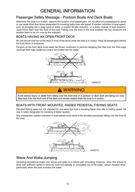
Passenger Safety Message - Pontoon Boats And Deck BoatsWhenever the boat is in motion, observe the location of all passengers. Do not allow any passengers to standor use seats other than those designated for traveling faster than idle speed. A sudden reduction in boat speed,such as plunging into a large wave or wake, a sudden throttle reduction, or a sharp change of boat direction,could throw them over the front of the boat. Falling over the front of the boat between the two pontoons willposition them to be run over by the outboard.
BOATS HAVING AN OPEN FRONT DECKNo one should ever be on the deck in front of the fence while the boat is in motion. Keep all passengers behindthe front fence or enclosure.Persons on the front deck could easily be thrown overboard or persons dangling their feet over the front edgecould get their legs caught by a wave and pulled into the water.
ob00312
! WARNINGAvoid serious injury or death from falling over the front end of a pontoon or deck boat and being run over.Stay back from the front end of the deck and remain seated while the boat is in motion.
BOATS WITH FRONT MOUNTED, RAISED PEDESTAL FISHING SEATSElevated fishing seats are not intended for use when the boat is traveling faster than idle or trolling speed. Sitonly in seats designated for traveling at faster speeds.Any unexpected, sudden reduction in boat speed could result in the elevated passenger falling over the front ofthe boat.
ob00313
Wave And Wake JumpingOperating recreational boats over waves and wake is a natural part of boating. However, when this activity isdone with sufficient speed to force the boat hull partially or completely out of the water, certain hazards arise,particularly when the boat re-enters the water.

GENERAL INFORMATION
14
ob00314
The primary concern is the boat changing direction while in the midst of the jump. In such case the landing maycause the boat to veer violently in a new direction. Such a sharp change in direction can cause occupants to bethrown out of their seats, or out of the boat.
! WARNINGAvoid serious injury or death from being thrown within or out of a boat when it lands after jumping a wave orwake. Avoid wave or wake jumping whenever possible. Instruct all occupants that if a wake or wave jumpoccurs, get low and hang on to a boat hand hold.
There is another less common hazardous result from allowing your boat to launch off a wave or wake. If the bowof your boat pitches down far enough while airborne, upon water contact it may penetrate under the water surfaceand submarine for an instant. This will bring the boat to a nearly instantaneous stop and can send the occupantsflying forward. The boat may also steer sharply to one side.
Impact With Underwater HazardsReduce speed and proceed with caution whenever you drive a boat in shallow water areas, or in areas whereyou suspect underwater obstacles may exist which could be struck by the outboard or the boat bottom. The mostimportant thing you can do to help reduce injury or impact damage from striking a floating or underwater objectis to control the boat speed. Under these conditions, boat speed should be kept to a minimum planing speed of24 to 40 km/h (15 to 25 MPH).
ob00315
! WARNINGTo avoid serious injury or death from all or part of an outboard coming into the boat after striking a floating orunderwater obstacle maintain a top speed no greater than minimum planing speed.
Striking a floating or underwater object could result in an infinite number of situations. Some of these situationscould result in the following:• Part of the outboard or the entire outboard could break loose and fly into the boat.
GENERAL INFORMATION
15
• The boat could move suddenly in a new direction. Such a sharp change in direction can cause occupantsto be thrown out of their seats or out of the boat.
• A rapid reduction in speed. This will cause occupants to be thrown forward, or even out of the boat.• Impact damage to the outboard and/or boat.Keep in mind, the most important thing you can do to help reduce injury or impact damage during an impact iscontrol the boat speed. Boat speed should be kept to a minimum planing speed when driving in waters knownto have underwater obstacles.After striking a submerged object, stop the engine as soon as possible and inspect it for any broken or looseparts. If damage is present or suspected, the outboard should be taken to an authorized dealer for a thoroughinspection and necessary repair.The boat should also be checked for any hull fractures, transom fractures, or water leaks.Operating a damaged outboard could cause additional damage to other parts of the outboard, or could affectcontrol of the boat. If continued running is necessary, do so at greatly reduced speeds.
! WARNINGAvoid serious injury or death from loss of boat control. Continued boating with major impact damage canresult in sudden outboard component failure with or without subsequent impacts. Have the outboardthoroughly inspected and any necessary repairs made.
Exhaust EmissionsBE ALERT TO CARBON MONOXIDE POISONINGCarbon monoxide is present in the exhaust fumes of all internal combustion engines. This includes the outboards,sterndrives and inboard engines that propel boats, as well as the generators that power various boat accessories.Carbon monoxide is a deadly gas that is odorless, colorless and tasteless.Early symptoms of carbon monoxide poisoning which should not be confused with seasickness or intoxication,include headache, dizziness, drowsiness, and nausea.
! WARNINGAvoid the combination of a running engine and poor ventilation. Prolonged exposure to carbon monoxide insufficient concentration can lead to unconsciousness, brain damage, or death.
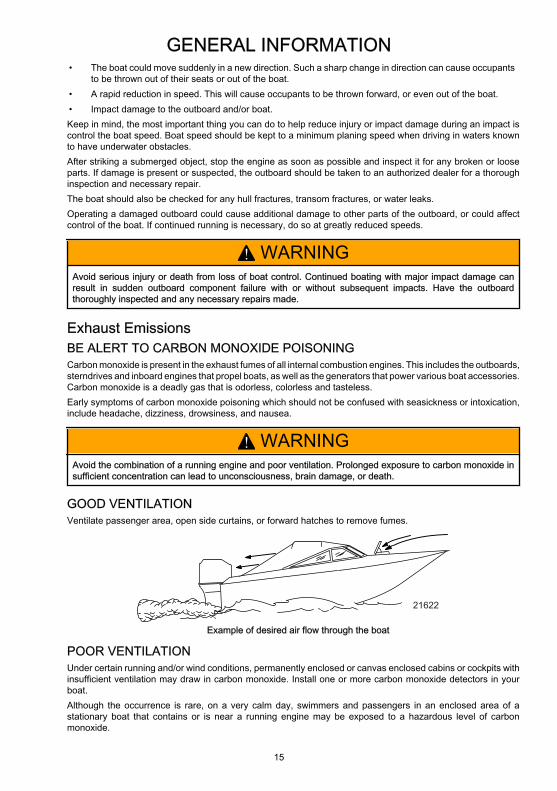
GOOD VENTILATIONVentilate passenger area, open side curtains, or forward hatches to remove fumes.
21622
Example of desired air flow through the boat
POOR VENTILATIONUnder certain running and/or wind conditions, permanently enclosed or canvas enclosed cabins or cockpits withinsufficient ventilation may draw in carbon monoxide. Install one or more carbon monoxide detectors in yourboat.Although the occurrence is rare, on a very calm day, swimmers and passengers in an enclosed area of astationary boat that contains or is near a running engine may be exposed to a hazardous level of carbonmonoxide.
GENERAL INFORMATION
16
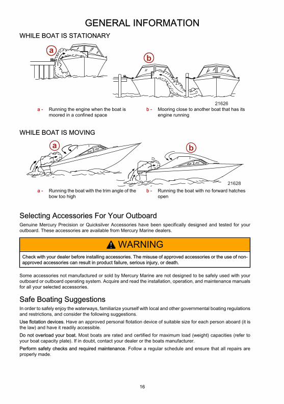
WHILE BOAT IS STATIONARY
21626
ab
a - Running the engine when the boat ismoored in a confined space
b - Mooring close to another boat that has itsengine running
WHILE BOAT IS MOVING
a b
21628a - Running the boat with the trim angle of the
bow too highb - Running the boat with no forward hatches
open
Selecting Accessories For Your OutboardGenuine Mercury Precision or Quicksilver Accessories have been specifically designed and tested for youroutboard. These accessories are available from Mercury Marine dealers.
! WARNINGCheck with your dealer before installing accessories. The misuse of approved accessories or the use of non-approved accessories can result in product failure, serious injury, or death.
Some accessories not manufactured or sold by Mercury Marine are not designed to be safely used with youroutboard or outboard operating system. Acquire and read the installation, operation, and maintenance manualsfor all your selected accessories.
Safe Boating SuggestionsIn order to safely enjoy the waterways, familiarize yourself with local and other governmental boating regulationsand restrictions, and consider the following suggestions.Use flotation devices. Have an approved personal flotation device of suitable size for each person aboard (it isthe law) and have it readily accessible.Do not overload your boat. Most boats are rated and certified for maximum load (weight) capacities (refer toyour boat capacity plate). If in doubt, contact your dealer or the boats manufacturer.Perform safety checks and required maintenance. Follow a regular schedule and ensure that all repairs areproperly made.

GENERAL INFORMATION
17
Know and obey all nautical rules and laws of the waterways. Boat operators should complete a boating safetycourse. Courses are offered in the U.S.A. by 1) The U.S. Coast Guard Auxiliary, 2) The Power Squadron, 3)The Red Cross and 4) your state boating law enforcement agency. Inquiries may be made to the Boating Hotline,1-800-368-5647 or the Boat U.S. Foundation information number 1-800-336-BOAT.Make sure everyone in the boat is properly seated. Do not allow anyone to sit or ride on any part of the boat thatwas not intended for such use. This includes the back of seats, gunwales, transom, bow, decks, raised fishingseats, any rotating fishing seat; or anywhere that an unexpected acceleration, sudden stopping, unexpectedloss of boat control, or sudden boat movement could cause a person to be thrown overboard or into the boat.Never be under the influence of alcohol or drugs while boating (it is the law). Alcohol or drug use impairs yourjudgment and greatly reduces your ability to react quickly.Prepare other boat operators. Instruct at least one other person on board in the basics of starting and operatingthe outboard, and boat handling, in case the driver becomes disabled or falls overboard.Passenger boarding. Stop the engine whenever passengers are boarding, unloading, or are near the back (stern)of the boat. Just shifting the outboard into neutral is not sufficient.Be alert. The operator of the boat is responsible by law to maintain a proper lookout by sight and hearing. Theoperator must have an unobstructed view particularly to the front. No passengers, load, or fishing seats shouldblock the operators view when operating the boat above idle speed.Never drive your boat directly behind a water skier in case the skier falls. As an example, your boat traveling at40 km/h (25 MPH) will overtake a fallen skier 61 m (200 ft.) in front of you in 5 seconds.Watch fallen skiers. When using your boat for water skiing or similar activities, always keep a fallen or downskier on the operator's side of the boat while returning to assist the skier. The operator should always have thedown skier in sight and never back up to the skier or anyone in the water.Report accidents. Boat operators are required by law to file a Boating Accident Report with their state boatinglaw enforcement agency when their boat is involved in certain boating accidents. A boating accident must bereported if 1) there is loss of life or probable loss of life, 2) there is personal injury requiring medical treatmentbeyond first aid, 3) there is damage to boats or other property where the damage value exceeds $500.00 or 4)there is complete loss of the boat. Seek further assistance from local law enforcement.
Recording Serial NumberIt is important to record this number for future reference. The serial number is located on the outboard as shown.
XXXX
XX
XXXXXXXX
XXXX
de
a bc
20880
a - Serial numberb - Model yearc - Model designation
d - Year manufacturede - Certified Europe Insignia (as applicable)
80/100/115 Specifications - International
Models 80/100/115
Horsepower 80/100/115
GENERAL INFORMATION
18
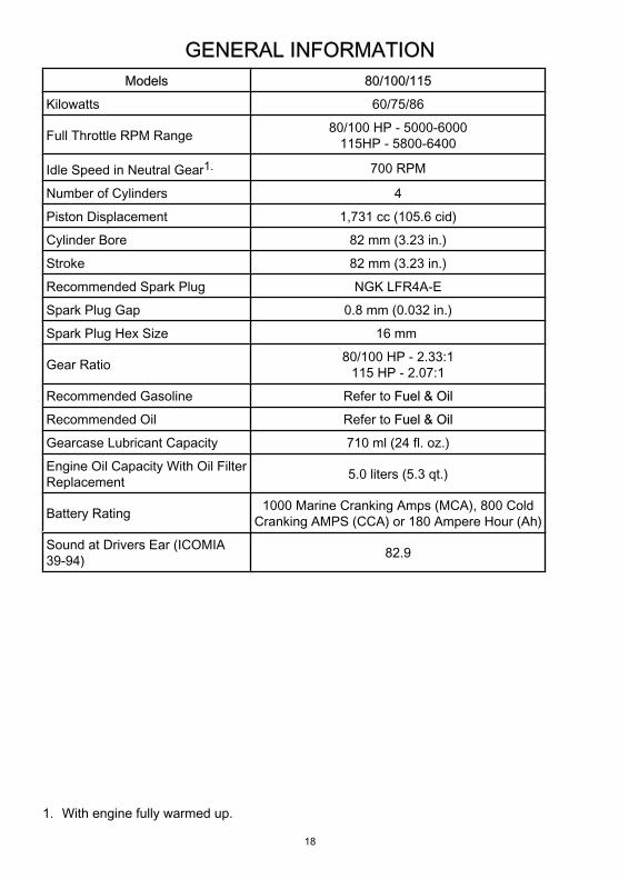
Models 80/100/115
Kilowatts 60/75/86
Full Throttle RPM Range 80/100 HP - 5000-6000115HP - 5800-6400
Idle Speed in Neutral Gear1. 700 RPM
Number of Cylinders 4
Piston Displacement 1,731 cc (105.6 cid)
Cylinder Bore 82 mm (3.23 in.)
Stroke 82 mm (3.23 in.)
Recommended Spark Plug NGK LFR4A-E
Spark Plug Gap 0.8 mm (0.032 in.)
Spark Plug Hex Size 16 mm
Gear Ratio 80/100 HP - 2.33:1115 HP - 2.07:1
Recommended Gasoline Refer to Fuel & Oil
Recommended Oil Refer to Fuel & Oil
Gearcase Lubricant Capacity 710 ml (24 fl. oz.)
Engine Oil Capacity With Oil FilterReplacement 5.0 liters (5.3 qt.)
Battery Rating 1000 Marine Cranking Amps (MCA), 800 ColdCranking AMPS (CCA) or 180 Ampere Hour (Ah)
Sound at Drivers Ear (ICOMIA39-94) 82.9
1. With engine fully warmed up.
GENERAL INFORMATION
19
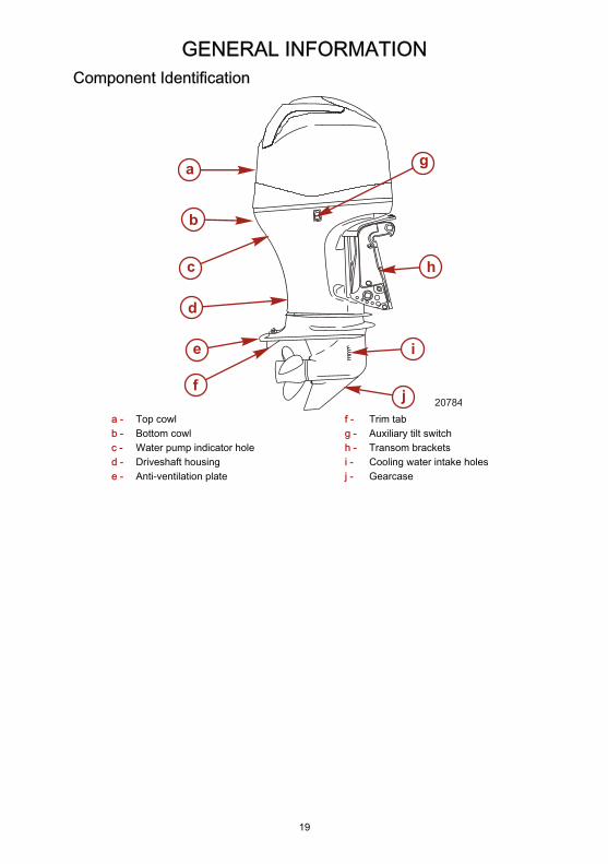
Component Identification
a
b
c
d
e
f
g
h
i
j 20784a - Top cowlb - Bottom cowlc - Water pump indicator holed - Driveshaft housinge - Anti-ventilation plate
f - Trim tabg - Auxiliary tilt switchh - Transom bracketsi - Cooling water intake holesj - Gearcase

TRANSPORTING
20
Trailering Boat/OutboardTrailer your boat with the outboard tilted down in a vertical operating position.If additional ground clearance is required, the outboard should be tilted up using an accessory outboard supportdevice. Refer to your local dealer for recommendations. Additional clearance may be required for railroadcrossings, driveways, and trailer bouncing.
20759
IMPORTANT: Do not rely on the power trim/tilt system or tilt support lever to maintain proper ground clearancefor trailering. The outboard tilt support lever is not intended to support the outboard for trailering.Shift the outboard to forward gear. This prevents the propeller from spinning freely.

FUEL AND OIL
21
Fuel RecommendationsIMPORTANT: Use of improper gasoline can damage your engine. Engine damage resulting from the use ofimproper gasoline is considered misuse of the engine, and damage caused thereby will not be covered underthe limited warranty.
FUEL RATINGSMercury Marine engines will operate satisfactorily when using a major brand of unleaded gasoline meeting thefollowing specifications:USA and Canada - having a posted pump Octane Rating of 87 (R+M)/2 minimum. Premium gasoline [92 (R+M)/2 Octane] is also acceptable. Do NOT use leaded gasoline.Outside USA and Canada - having a posted pump Octane Rating of 90 RON minimum. Premium gasoline (98RON) is also acceptable. If unleaded gasoline is not available, use a major brand of leaded gasoline.
USING REFORMULATED (OXYGENATED) GASOLINES (USA ONLY)This type of gasoline is required in certain areas of the USA. The 2 types of oxygenates used in these fuels areAlcohol (Ethanol) or Ether (MTBE or ETBE). If Ethanol is the oxygenate that is used in the gasoline in your area,refer to Gasolines Containing Alcohol.These Reformulated Gasolines are acceptable for use in your Mercury Marine engine.
GASOLINES CONTAINING ALCOHOLIf the gasoline in your area contains either methanol (methyl alcohol) or ethanol (ethyl alcohol), you should beaware of certain adverse effects that can occur. These adverse effects are more severe with methanol.Increasing the percentage of alcohol in the fuel can also worsen these adverse effects.Some of these adverse effects are caused because the alcohol in the gasoline can absorb moisture from theair, resulting in a separation of the water/alcohol from the gasoline in the fuel tank.The fuel system components on your Mercury Marine engine will withstand up to 10% alcohol content in thegasoline. We do not know what percentage your boat's fuel system will withstand. Contact your boatmanufacturer for specific recommendations on the boat's fuel system components (fuel tanks, fuel lines, andfittings). Be aware that gasolines containing alcohol may cause increased:• Corrosion of metal parts• Deterioration of rubber or plastic parts• Fuel permeation through rubber fuel lines• Starting and operating difficulties
! WARNINGFIRE AND EXPLOSION HAZARD: Fuel leakage from any part of the fuel system can be a fire and explosionhazard which can cause serious bodily injury or death. Careful periodic inspection of entire fuel system ismandatory, particularly after storage. All fuel components should be inspected for leakage, softening,hardening, swelling or corrosion. Any sign of leakage or deterioration requires replacement before furtherengine operation.
Because of possible adverse effects of alcohol in gasoline, it is recommended that only alcohol-free gasoline beused where possible. If only fuel containing alcohol is available, or if the presence of alcohol is unknown,increased inspection frequency for leaks and abnormalities is required.IMPORTANT: When operating a Mercury Marine engine on gasoline containing alcohol, storage of gasoline inthe fuel tank for long periods should be avoided. Long periods of storage, common to boats, create uniqueproblems. In cars, alcohol-blend fuels normally are consumed before they can absorb enough moisture to causetrouble, but boats often sit idle long enough for phase separation to take place. In addition, internal corrosionmay take place during storage if alcohol has washed protective oil films from internal components.

FUEL AND OIL
22
Filling Fuel Tank
! WARNINGAvoid serious injury or death from a gasoline fire or explosion. Always stop the engine and do not smoke orallow open flames or sparks in the area while filling fuel tanks.
Fill fuel tanks outdoors away from heat, sparks, and open flames.Remove portable fuel tanks from boat to refill them.Always stop engine before refilling tanks.Do not completely fill the fuel tanks. Leave approximately 10% of the tank volume unfilled. Fuel will expand involume as its temperature rises and can leak under pressure if the tank is completely filled.
PORTABLE FUEL TANK PLACEMENT IN THE BOATPlace the fuel tank in the boat so the vent is higher than the fuel level under normal boat operating conditions.
Engine Oil RecommendationsMercury or Quicksilver NMMA FC-W certified synthetic blend 25W-40 multi-viscosity 4-Stroke Outboard Oil isrecommended for general, all-temperature use. If the recommended Mercury or Quicksilver NMMA FC-Wcertified oil is not available, a major brand of NMMA FC-W certified 4-Stroke Outboard Oil of similar viscositymay be used.IMPORTANT: The use of non-detergent oils, multi-viscosity oils (other than Mercury or Quicksilver NMMA FC-W certified oil or a major brand NMMA FC-W certified oil), synthetic oils, low quality oils or oils that contain solidadditives are not recommended.
C
+100+80+60+40+20
0
+38+120 +49
+27+16+4-7-18
F
MERCURY 4-STROKE ENGINE OILOIL CAPACITY: 5.0L (5.3 U.S.qt.)
20862
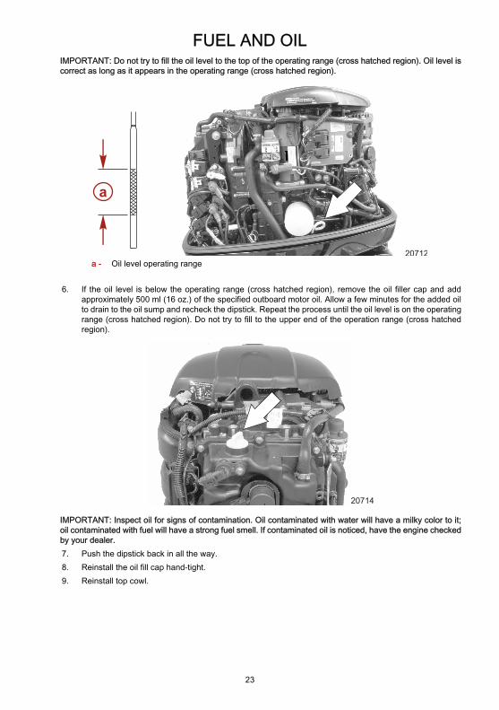
Checking and Adding Engine OilIMPORTANT: Do not overfill. Tilt outboard out/up past vertical for approximately one minute to allow trapped oilto drain back to the oil sump. Tilt outboard to vertical (not tilted) position when checking engine oil. For accuratereadings, check oil only when engine is cold or after engine has not run for at least an hour.1. Before starting (cold engine) tilt outboard out/up past vertical to allow trapped oil to drain back to the oil
sump. Allow outboard to remain tilted for approximately one minute.2. Tilt outboard to vertical operating position.3. Remove the top cowl. Refer to Maintenance - Top Cowl Removal and Installation.4. Pull out the dipstick. Wipe the dipstick end with a clean rag or towel and push it back in all the way.5. Pull the dipstick back out again and observe the oil level. Oil should be in the operating range (cross
hatched region).
FUEL AND OIL
23
IMPORTANT: Do not try to fill the oil level to the top of the operating range (cross hatched region). Oil level iscorrect as long as it appears in the operating range (cross hatched region).
a
20712a - Oil level operating range
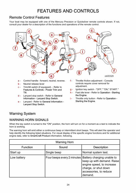
6. If the oil level is below the operating range (cross hatched region), remove the oil filler cap and addapproximately 500 ml (16 oz.) of the specified outboard motor oil. Allow a few minutes for the added oilto drain to the oil sump and recheck the dipstick. Repeat the process until the oil level is on the operatingrange (cross hatched region). Do not try to fill to the upper end of the operation range (cross hatchedregion).
20714
IMPORTANT: Inspect oil for signs of contamination. Oil contaminated with water will have a milky color to it;oil contaminated with fuel will have a strong fuel smell. If contaminated oil is noticed, have the engine checkedby your dealer.7. Push the dipstick back in all the way.8. Reinstall the oil fill cap hand-tight.9. Reinstall top cowl.
FEATURES AND CONTROLS
24
Remote Control FeaturesYour boat may be equipped with one of the Mercury Precision or Quicksilver remote controls shown. If not,consult your dealer for a description of the functions and operations of the remote control.
ee
aa
dd dd
eeffgg
aa
bbff
cc
gghh
bbcc
aa
ff
ii
cc
ii
ob00329
a - Control handle - forward, neutral, reverse.b - Neutral release leverc - Trim/tilt switch (if equipped). - Refer to
Features & Controls - Power Trim andTilt.
d - Lanyard stop switch - Refer to GeneralInformation - Lanyard Stop Switch.
e - Lanyard - Refer to General Information -Lanyard Stop Switch.
f - Throttle friction adjustment - Consolecontrols require cover removal foradjustment.
g - Ignition key switch - "OFF," "ON," START."h - Fast idle lever - Refer to Operation - Starting
the Engine.i - Throttle only button - Refer to Operation -
Starting the Engine.
Warning System
WARNING HORN SIGNALSWhen the key switch is turned to the "ON" position, the horn will turn on for a moment as a test to indicate thehorn is working.The warning horn will emit either a continuous beep or intermittent short beeps. This will alert the operator andhelp identify the following listed situations. For visual display of the specific engine functions and for additionalengine data, refer to SmartCraft Product information, following.
Warning Horn
Function Sound Description
Start up Single beep Normal system test.
Low battery Four beeps every 2 minutes Battery charging unable tokeep up with demand. Raiseengine speed, to increasecharge, or shut downaccessories, to reducedemand.
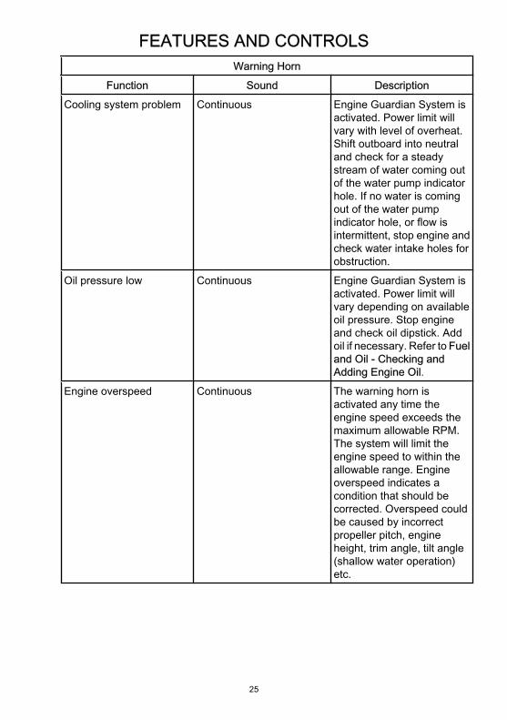
FEATURES AND CONTROLS
25
Warning Horn
Function Sound Description
Cooling system problem Continuous Engine Guardian System isactivated. Power limit willvary with level of overheat.Shift outboard into neutraland check for a steadystream of water coming outof the water pump indicatorhole. If no water is comingout of the water pumpindicator hole, or flow isintermittent, stop engine andcheck water intake holes forobstruction.
Oil pressure low Continuous Engine Guardian System isactivated. Power limit willvary depending on availableoil pressure. Stop engineand check oil dipstick. Addoil if necessary. Refer to Fueland Oil - Checking andAdding Engine Oil.
Engine overspeed Continuous The warning horn isactivated any time theengine speed exceeds themaximum allowable RPM.The system will limit theengine speed to within theallowable range. Engineoverspeed indicates acondition that should becorrected. Overspeed couldbe caused by incorrectpropeller pitch, engineheight, trim angle, tilt angle(shallow water operation)etc.

FEATURES AND CONTROLS
26
Warning Horn
Function Sound Description
Sensor/Actuator out ofrange
Single beep (enginerunning)
May be a problem with oneof the engine functions.Have your dealer check theengine soon.
Continuous Engine Guardian System isactivated. Power limit willrestrict engine speed toeither idle or 55%,depending on fault.
ENGINE GUARDIAN SYSTEMThe Engine Guardian System monitors the critical sensors on the engine for any early indications of problems.The system will respond to a problem by emitting a continuous beep and/or reducing engine power in order toprovide engine protection.If Guardian System has been activated, reduce throttle speed. The problem will need to be identified andcorrected, if possible. The system must be reset before the engine will operate at higher speeds. Moving thethrottle lever back to the idle position will reset the system.
SMARTCRAFT PRODUCTA Mercury SmartCraft System instrument package can be purchased for this outboard. A few of the functionsthe instrument package will display are engine RPM, coolant temperature, oil pressure, water pressure, batteryvoltage, fuel consumption and engine operating hours.The SmartCraft Instrument package will also aid in Engine Guardian diagnostics. The SmartCraft Instrumentpackage will display critical engine alarm data and potential problems.
Power Trim and TiltThe outboard has a trim/tilt control called power trim. This enables the operator to easily adjust the position ofthe outboard by pressing the trim switch. Moving the outboard in closer to the boat transom is called trimmingin or down. Moving the outboard further away from the boat transom is called trimming out or up. The term trimgenerally refers to the adjustment of the outboard within the first 20° range of travel. This is the range used whileoperating the boat on plane. The term tilt is generally used when referring to adjusting the outboard further upout of the water. With the engine turned off and ignition switch turned on, the outboard can be tilted out of thewater. At low idle speed, the outboard can also be tilted up past the trim range to permit, for example, shallowwater operation.

FEATURES AND CONTROLS
27
a
cb 20760
a - Trim switchb - Tilt range
c - Trim range
POWER TRIM OPERATIONWith most boats, operating around the middle of the trim range will give satisfactory results. However, to takefull advantage of the trimming capability there may be times when you choose to trim your outboard all the wayin or out. Along with an improvement in some performance aspects comes a greater responsibility for theoperator, and this is being aware of some potential control hazards.The most significant control hazard is a pull or torque that can be felt on the steering wheel or tiller handle. Thissteering torque results from the outboard being trimmed so that the propeller shaft is not parallel to the watersurface.
! WARNINGAvoid possible serious injury or death. When the outboard is trimmed in or out beyond a neutral steeringcondition, a pull on the steering wheel or tiller handle in either direction may result. Failure to keep a continuousfirm grip on the steering wheel or tiller handle when this condition exists can result in loss of boat control asthe outboard can turn freely. The boat can now spin out or go into a very tight maximum turn which, ifunexpected, can result in occupants being thrown within the boat or out of the boat.
Consider the following lists carefully.1. Trimming In or Down Can:
• Lower the bow.• Result in quicker planing off, especially with a heavy load or a stern heavy boat.• Generally improve the ride in choppy water.• Increase steering torque or pull to the right (with the normal right hand rotation propeller).• In excess can lower the bow of some boats to a point where they begin to plow with their bow in the
water while on plane. This can result in an unexpected turn in either direction (called bow steeringor over-steering) if any turn is attempted, or if a significant wave is encountered.
! WARNINGAvoid possible serious injury or death. Adjust outboard to an intermediate trim position as soon as boat ison plane to avoid possible ejection due to boat spin out. Do not attempt to turn boat when on plane ifoutboard is trimmed extremely in or down and there is a pull on the steering wheel or tiller handle.
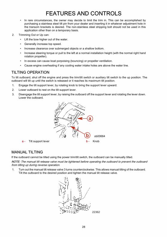
FEATURES AND CONTROLS
28
• In rare circumstances, the owner may decide to limit the trim in. This can be accomplished bypurchasing a stainless steel tilt pin from your dealer and inserting it in whatever adjustment hole inthe transom brackets is desired. The non-stainless steel shipping bolt should not be used in thisapplication other than on a temporary basis.
2. Trimming Out or Up can:• Lift the bow higher out of the water.• Generally increase top speed.• Increase clearance over submerged objects or a shallow bottom.• Increase steering torque or pull to the left at a normal installation height (with the normal right hand
rotation propeller).• In excess can cause boat porpoising (bouncing) or propeller ventilation.• Cause engine overheating if any cooling water intake holes are above the water line.
TILTING OPERATIONTo tilt outboard, shut off the engine and press the trim/tilt switch or auxiliary tilt switch to the up position. Theoutboard will tilt up until the switch is released or it reaches its maximum tilt position.1. Engage the tilt support lever, by rotating knob to bring the support lever upward.2. Lower outboard to rest on the tilt support lever.3. Disengage the tilt support lever, by raising the outboard off the support lever and rotating the lever down.
Lower the outboard.
a
b ob00664
a - Tilt support lever b - Knob
MANUAL TILTINGIf the outboard cannot be tilted using the power trim/tilt switch, the outboard can be manually tilted.NOTE: The manual tilt release valve must be tightened before operating the outboard to prevent the outboardfrom tilting up during reverse operation.1. Turn out the manual tilt release valve 3 turns counterclockwise. This allows manual tilting of the outboard.
Tilt the outboard to the desired position and tighten the manual tilt release valve.
22362
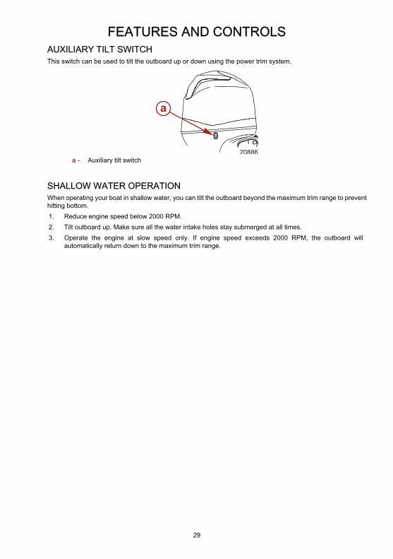
FEATURES AND CONTROLS
29
AUXILIARY TILT SWITCHThis switch can be used to tilt the outboard up or down using the power trim system.
a
20886a - Auxiliary tilt switch
SHALLOW WATER OPERATIONWhen operating your boat in shallow water, you can tilt the outboard beyond the maximum trim range to preventhitting bottom.1. Reduce engine speed below 2000 RPM.2. Tilt outboard up. Make sure all the water intake holes stay submerged at all times.3. Operate the engine at slow speed only. If engine speed exceeds 2000 RPM, the outboard will
automatically return down to the maximum trim range.
OPERATION
30
Pre-Starting Check List• Operator knows safe navigation, boating, and operating procedures.• An approved personal flotation device of suitable size for each person aboard and readily accessible (it
is the law).• A ring type life buoy or buoyant cushion designed to be thrown to a person in the water.• Know your boats maximum load capacity. Look at the boat capacity plate.• Fuel supply OK.• Arrange passengers and load in the boat so the weight is distributed evenly and everyone is seated in a
proper seat.• Tell someone where you are going and when you expect to return.• It is illegal to operate a boat while under the influence of alcohol or drugs.• Know the waters and area you will be boating; tides, currents, sand bars, rocks, and other hazards.• Make inspection checks listed in Maintenance - Inspection and Maintenance Schedule.
Operating In Freezing TemperaturesWhen using your outboard or having your outboard moored in freezing or near freezing temperatures, keep theoutboard tilted down at all times so the gearcase is submerged. This prevents trapped water in gearcase fromfreezing and causing possible damage to the water pump and other components.If there is a chance of ice forming on the water, the outboard should be removed and drained completely ofwater. If ice should form at the water level inside the outboard driveshaft housing, it will block water flow to theengine causing possible damage.
Operating In Salt Water Or Polluted WaterWe recommend that you flush the internal water passages of your outboard with fresh water after each use insalt or polluted water. This will prevent a buildup of deposits from clogging the water passages. Refer toMaintenance - Flushing The Cooling System.If you keep your boat moored in the water, always tilt the outboard so the gearcase is completely out of water(except in freezing temperatures) when not in use.Wash the outboard exterior and flush out the exhaust outlet of the propeller and gearcase with fresh water aftereach use. Each month, spray Mercury Precision or Quicksilver Corrosion Guard on external metal surfaces. Donot spray on corrosion control anodes as this will reduce the effectiveness of the anodes.
Setting Trim Angle while Running Engine at Idle SpeedThe exhaust relief hole on the outboard can become submerged on some boats if the engine is trimmed full inwhile running at idle speed. This may result in exhaust restriction, rough idle, excessive smoke, and fouled sparkplugs. If this condition exists, trim outboard up until exhaust relief hole is out of the water.

OPERATION
31
a b
20776
a - Relief hole submerged (wrong) b - Relief hole above water line (correct)
Engine Break-in Procedure
! CAUTIONSevere damage to the engine can result by not complying with the Engine Break-in Procedure.
1. For the first two hours of operation, run the engine at varied throttle settings up to 4500 RPM or at three-quarter throttle, and at full throttle for approximately one minute every ten minutes.
2. For the next eight hours of operation, avoid continuous operation at full throttle for more than five minutesat a time.
Starting The Engine - Remote Control ModelsBefore starting, read the Pre-Starting Check List, and Engine Break-in Procedure in the Operation section.
! CAUTIONNever start or operate your outboard (even momentarily) without water circulating through all the cooling waterintake holes in the gearcase to prevent damage to the water pump (running dry) or overheating of the engine.
1. Check the engine oil level.
20783
2. Ensure the cooling water intake is submerged.
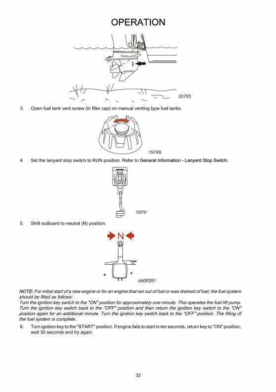
OPERATION
32
20765
3. Open fuel tank vent screw (in filler cap) on manual venting type fuel tanks.
19748
4. Set the lanyard stop switch to RUN position. Refer to General Information - Lanyard Stop Switch.
19791
5. Shift outboard to neutral (N) position.
N
ob00351
NOTE: For initial start of a new engine or for an engine that ran out of fuel or was drained of fuel, the fuel systemshould be filled as follows:Turn the ignition key switch to the "ON" position for approximately one minute. This operates the fuel lift pump.Turn the ignition key switch back to the "OFF" position and then return the ignition key switch to the "ON"position again for an additional minute. Turn the ignition key switch back to the "OFF" position. The filling ofthe fuel system is complete.6. Turn ignition key to the "START" position. If engine fails to start in ten seconds, return key to "ON" position,
wait 30 seconds and try again.

OPERATION
33
19804
7. After engine starts, check for a steady stream of water flowing out of the water pump indicator hole.
20766
IMPORTANT: If no water is coming out of the water pump indicator hole, stop engine and check cooling waterintake for obstruction. No obstruction may indicate a water pump failure or blockage in the cooling system.These conditions will cause the engine to overheat. Have the outboard checked by your dealer. Operating theengine while overheated will cause engine damage.
WARMING UP ENGINEBefore beginning operation, allow the engine to warm up at idling speed for three minutes.
Gear ShiftingIMPORTANT: Observe the following:• Never shift outboard into gear unless engine speed is at idle.• Do not shift outboard into reverse when the engine is not running.• Your outboard has three gear shift positions to provide operation. Forward (F), Neutral (N) and Reverse
(R).• When shifting, always stop at neutral position and allow the engine speed to return to idle.• Always shift outboard into gear with a quick motion.• After shifting outboard into gear, advance the lever further to increase speed.
N RF
ob00557
Stopping The EngineReduce engine speed and shift outboard to neutral position. Turn ignition key to "OFF" position.

OPERATION
34
ob00360
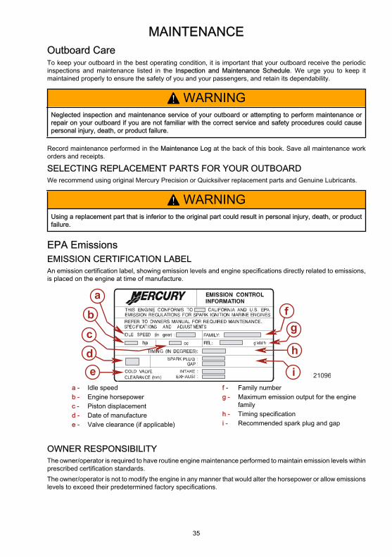
MAINTENANCE
35
Outboard CareTo keep your outboard in the best operating condition, it is important that your outboard receive the periodicinspections and maintenance listed in the Inspection and Maintenance Schedule. We urge you to keep itmaintained properly to ensure the safety of you and your passengers, and retain its dependability.
! WARNINGNeglected inspection and maintenance service of your outboard or attempting to perform maintenance orrepair on your outboard if you are not familiar with the correct service and safety procedures could causepersonal injury, death, or product failure.
Record maintenance performed in the Maintenance Log at the back of this book. Save all maintenance workorders and receipts.
SELECTING REPLACEMENT PARTS FOR YOUR OUTBOARDWe recommend using original Mercury Precision or Quicksilver replacement parts and Genuine Lubricants.
! WARNINGUsing a replacement part that is inferior to the original part could result in personal injury, death, or productfailure.
EPA EmissionsEMISSION CERTIFICATION LABELAn emission certification label, showing emission levels and engine specifications directly related to emissions,is placed on the engine at time of manufacture.
edc
b
afg
h
i 21096
a - Idle speedb - Engine horsepowerc - Piston displacementd - Date of manufacturee - Valve clearance (if applicable)
f - Family numberg - Maximum emission output for the engine
familyh - Timing specificationi - Recommended spark plug and gap
OWNER RESPONSIBILITYThe owner/operator is required to have routine engine maintenance performed to maintain emission levels withinprescribed certification standards.The owner/operator is not to modify the engine in any manner that would alter the horsepower or allow emissionslevels to exceed their predetermined factory specifications.

MAINTENANCE
36
Inspection and Maintenance ScheduleBEFORE EACH USE• Check engine oil level. See Fuel and Oil - Checking and Adding Engine Oil.• Check that lanyard stop switch stops the engine.• Visually inspect the fuel system for deterioration or leaks.• Check outboard for tightness on transom.• Check steering system for binding or loose components.• Check propeller blades for damage.
AFTER EACH USE• Flush out the outboard cooling system if operating in salt or polluted water. See Flushing the Cooling
System.• Wash off all salt deposits and flush out the exhaust outlet of the propeller and gearcase with fresh water
if operating in saltwater.• If operating in saltwater, inspect the powerhead and powerhead components for salt build-up. See
Cleaning Care for the Powerhead (Saltwater Use).
EVERY 100 HOURS OF USE OR ONCE YEARLY, WHICHEVER OCCURSFIRST• Change engine oil and replace the oil filter. The oil should be changed more often when the engine is
operated under adverse conditions such as extended trolling. See Changing Engine Oil.• Inspect the thermostat visually for corrosion and or for a broken spring. Make sure the thermostat closes
completely at room temperature.1.• Check low pressure fuel filter for contaminants. Replace filter if required. See Fuel System.• Check corrosion control anodes. Check more frequently when used in saltwater. See Corrosion Control
Anode.• Drain and replace gearcase lubricant. See Gearcase Lubrication.• Check power trim fluid. See Checking Power Trim Fluid.• Inspect battery. See Battery Inspection.• Saltwater usage. Remove and inspect spark plugs for corrosion and replace spark plugs as necessary.
Apply a thin coating of Anti-Seize Compound only on threads of spark plug prior to installation. See SparkPlug Inspection and Replacement.
Tube Ref No. Description Where Used Part No.
81 Anti-Seize Compound Spark plug threads 92-881091K1
• Check wiring and connectors.• Check tightness of bolts, nuts, and other fasteners.• Check cowl seals to make sure seals are intact and not damaged.• Check internal cowl sound reduction foam (if equipped) to make sure foam is intact and not damaged.• Check that the intake silencer (if equipped) is in place.• Check that the idle relief muffler (if equipped) is in place.• Check for loose hose clamps and rubber boots (if equipped) on the air intake assembly.
EVERY 300 HOURS OF USE OR THREE YEARS• Replace water pump impeller (more often if overheating occurs or reduced water pressure is noted).1.
1. These items should be serviced by an authorized dealer.
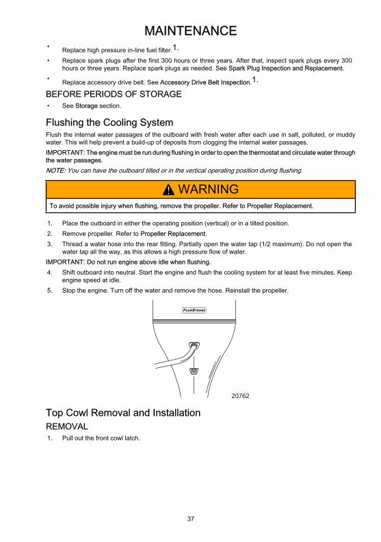
MAINTENANCE
37
• Replace high pressure in-line fuel filter.1.• Replace spark plugs after the first 300 hours or three years. After that, inspect spark plugs every 300
hours or three years. Replace spark plugs as needed. See Spark Plug Inspection and Replacement.• Replace accessory drive belt. See Accessory Drive Belt Inspection.1.
BEFORE PERIODS OF STORAGE• See Storage section.
Flushing the Cooling SystemFlush the internal water passages of the outboard with fresh water after each use in salt, polluted, or muddywater. This will help prevent a build-up of deposits from clogging the internal water passages.IMPORTANT: The engine must be run during flushing in order to open the thermostat and circulate water throughthe water passages.NOTE: You can have the outboard tilted or in the vertical operating position during flushing.
! WARNINGTo avoid possible injury when flushing, remove the propeller. Refer to Propeller Replacement.
1. Place the outboard in either the operating position (vertical) or in a tilted position.2. Remove propeller. Refer to Propeller Replacement.3. Thread a water hose into the rear fitting. Partially open the water tap (1/2 maximum). Do not open the
water tap all the way, as this allows a high pressure flow of water.IMPORTANT: Do not run engine above idle when flushing.4. Shift outboard into neutral. Start the engine and flush the cooling system for at least five minutes. Keep
engine speed at idle.5. Stop the engine. Turn off the water and remove the hose. Reinstall the propeller.
OUR TRF S OKE
20762
Top Cowl Removal and InstallationREMOVAL1. Pull out the front cowl latch.
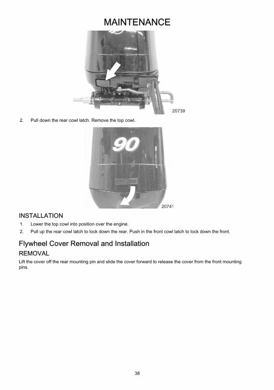
MAINTENANCE
38
20739
2. Pull down the rear cowl latch. Remove the top cowl.
20741
INSTALLATION1. Lower the top cowl into position over the engine.2. Pull up the rear cowl latch to lock down the rear. Push in the front cowl latch to lock down the front.
Flywheel Cover Removal and InstallationREMOVALLift the cover off the rear mounting pin and slide the cover forward to release the cover from the front mountingpins.

MAINTENANCE
39
20910
a
b
c
a - Flywheel coverb - Front mounting pins
c - Rear mounting pin
INSTALLATIONPosition the cover onto the two front pins and then secure the cover in place by pushing the cover down ontothe rear mounting pin.
Cleaning Care for Top and Bottom CowlsIMPORTANT: Dry wiping (wiping the plastic surface when it is dry) will result in minor surface scratches. Alwayswet the surface before cleaning. Do not use detergents containing hydrochloric acid. Follow the cleaning andwaxing procedure.
CLEANING AND WAXING PROCEDURE1. Before washing, rinse the cowls with clean water to remove dirt and dust that may scratch the surface.2. Wash the cowls with clean water and a mild non-abrasive soap. Use a soft clean cloth when washing.3. Dry thoroughly with a soft clean cloth.4. Wax the surface using a non-abrasive automotive polish (polish designed for clear coat finishes). Remove
the applied wax by hand using a clean soft cloth.5. To remove minor scratches, use Mercury Marine Cowl Finishing Compound (92-859026K 1).
Cleaning Care for the Powerhead (Saltwater Use)If the outboard is operated in saltwater, remove the top cowl and flywheel cover. Inspect the powerhead andpowerhead components for salt build-up. Wash off any salt build-up from the powerhead and powerheadcomponents with fresh water. Keep water spray out of the air filter/intake and alternator. After washing, allowthe powerhead and components to dry. Apply Quicksilver or Mercury Precision Lubricants Corrosion Guardspray on the external metal surfaces of the powerhead and powerhead components. Do not allow the CorrosionGuard spray to come in contact with the alternator drive belt or belt pulleys.IMPORTANT: Do not allow lubricant or Corrosion Guard spray to come in contact with the alternator drive beltor the belt pulleys. The alternator drive belt could slip and be damaged if it becomes coated with any lubricantor Corrosion Guard spray.

MAINTENANCE
40
Tube Ref No. Description Where Used Part No.
120 Corrosion Guard
External metal surfacesof the powerhead and
powerheadcomponents.
92-802878Q55
Battery InspectionThe battery should be inspected at periodic intervals to ensure proper engine starting capability.IMPORTANT: Read the safety and maintenance instructions which accompany your battery.1. Turn off the engine before servicing the battery.2. Add water as necessary to keep the battery full.3. Make sure the battery is secure against movement.4. Battery cable terminals should be clean, tight, and correctly installed. Positive to positive and negative to
negative.5. Make sure the battery is equipped with a non-conductive shield to prevent accidental shorting of battery
terminals.
Air FilterThe air filter is a one piece assembly. The air filter removes airborne particles which may damage enginecomponents. The air filter design allows for maximum unrestricted air flow during engine operation.
AIR FILTER ASSEMBLY REMOVAL1. Remove the breather tube from the air filter.
a
b
20773
c
a - Air filter assemblyb - Breather tube
c - Air intake
2. Remove the purge vent tube from the air filter.3. Pull the air filter assembly off the front of the air intake.NOTE: To help in the removal of the air filter assembly, use the bottom tab that is located on the mountingflange of the filter and push out on the flange while pulling the air filter assembly off the air intake.

MAINTENANCE
41
a
20817
b
a - Purge vent tube b - Bottom tab
AIR FILTER ASSEMBLY INSTALLATION1. Place the air filter assembly over the air intake as shown and then push the air filter assembly onto the
air intake until it is fully seated.2. Reconnect the breather tube and purge vent tube to the air filter.
Fuel System
! WARNINGAvoid serious injury or death from gasoline fire or explosion. Carefully follow all fuel system serviceinstructions. Always stop the engine and do not smoke or allow open flames or sparks in the area whileservicing any part of the fuel system.
IMPORTANT: Use an approved container to collect and store fuel. Wipe up spilled fuel immediately. Materialused to contain spilled fuel must be disposed of in an approved receptacle.Before servicing any part of the fuel system:1. Stop engine and disconnect the battery.2. Perform fuel system service in a well ventilated area.3. Inspect any completed service work for sign of fuel leakage.
FUEL LINE INSPECTIONVisually inspect the fuel line for cracks, swelling, leaks, hardness, or other signs of deterioration or damage. Ifany of these conditions are found, the fuel line must be replaced.
FUEL FILTERSRefer to the Inspection and Maintenance Schedule for the proper maintenance interval.The engine is equipped with two fuel filters, One low pressure filter and one high pressure filter. The low pressurefilter can be serviced as a general maintenance item, however the high pressure filter is under high pressureand should only be serviced by an authorized dealer.

MAINTENANCE
42
ab
20808a - Low pressure fuel filter b - High pressure fuel filter
HIGH PRESSURE FUEL FILTERThe high pressure fuel filter is under high pressure. A special tool and procedure is required to release the fuelpressure before the filter can be removed. Have the high pressure fuel filter serviced by an authorized dealer.
LOW PRESSURE FUEL FILTERRemoval1. Turn ignition key switch to "OFF" position.2. Remove the cap from the fuel vapor purge relief valve.
a
20813a - Fuel vapor purge relief valve

MAINTENANCE
43
! CAUTIONFuel vapor vent system is under pressure. Cover valve assembly with a rag or towel to prevent fuel or fuelvapor spray. Relieve pressure slowly.
3. Place a rag or towel around the valve, and release the fuel pressure by pushing the core of the valve endin.
132824. Push in on the fuel hose release tabs and disconnect the fuel hoses from the fuel filter.
a
a
20815
b
a - Fuel hose release tab b - Low pressure fuel filter
Installation1. Install the new fuel filter so the arrow points towards the engine.2. Connect the fuel hoses to the fuel filter securely with the locking hose connections.3. If removed, place the fuel hose into the fuel hose retainer.

MAINTENANCE
44
a
20888a - Fuel hose retainer
4. Visually inspect for fuel leakage from the fuel filter while turning the ignition key to "RUN" position, forcingfuel into the fuel filter. Repair any fuel leaks if necessary.
Corrosion Control AnodeThe outboard has corrosion control anodes at different locations. An anode helps protect the outboard againstgalvanic corrosion by sacrificing its metal to be slowly eroded instead of the outboard metals.Each anode requires periodic inspection, especially in saltwater which will accelerate the erosion. To maintainthis corrosion protection, always replace the anode before it is completely eroded. Never paint or apply aprotective coating on the anode as this will reduce effectiveness of the anode.Two anodes are located on each side of the gearcase. Another anode is installed on the bottom of the transombracket assembly.
20761
Propeller Replacement
! WARNINGIf the propeller shaft is rotated while the engine is in gear, there is the possibility that the engine will crankover and start. To prevent this type of accidental engine starting and possible serious injury caused from beingstruck by a rotating propeller, always shift outboard to neutral position and remove spark plug leads whenyou are servicing the propeller.

MAINTENANCE
45
1. Shift outboard to neutral (N) position.
N
ob00351
2. Straighten the bent tabs on the propeller nut retainer.
ob00376
3. Place a block of wood between gearcase and propeller to hold propeller and remove propeller nut.
ob00377
4. Pull propeller straight off shaft.5. Coat the propeller shaft with Quicksilver or Mercury Precision Lubricants Anti-Corrosion Grease or 2-4-
C with Teflon.
ob00378
Tube Ref No. Description Where Used Part No.
94 Anti-Corrosion Grease Propeller shaft 92-802867Q1
95 2-4-C Marine Lubricantwith Teflon Propeller shaft 92-802859Q1

MAINTENANCE
46
IMPORTANT: To prevent the propeller hub from corroding and seizing to the propeller shaft, especially in saltwater, always apply a coat of the recommended lubricant to the entire propeller shaft at the recommendedmaintenance intervals and also each time the propeller is removed.6. Flo-Torq I Drive Hub Propellers - Install thrust washer, propeller, continuity washer, thrust hub, propeller
nut retainer, and propeller nut onto the shaft.
ob00382
a b c
d e fa - Propeller nutb - Propeller nut retainerc - Rear thrust hub
d - Continuity washere - Propellerf - Forward thrust hub
7. Flo-Torq II and Flo-Torq III Drive Hub Propellers - Install forward thrust hub, replaceable drive sleeve,propeller, thrust hub, propeller nut retainer and propeller nut onto the shaft.
b ca
d
fe
ob00421
3223a b c d e fFlo-Torq II Flo-Torq III
a - Propeller nutb - Propeller nut retainerc - Rear thrust hub
d - Propellere - Replaceable drive sleevef - Forward thrust hub
8. Place a block of wood between the gearcase and propeller. Torque propeller nut to specifications.
Description Nm lb. in. lb. ft.
Propeller nut 75 55

MAINTENANCE
47
9. Secure propeller nut by bending three of the tabs into the thrust hub grooves.
ob00422
10. Reinstall spark plug leads.
Spark Plug Inspection and Replacement1. Remove top cowling. Refer to Top Cowl Removal and Installation.2. Disconnect the wiring harness connectors from the pencil coils.3. Remove the mounting bolts that are securing the pencil coils. Pull the pencil coils from the spark plugs
using a twisting motion.
a
b
d
c
20752a - Wiring harness connectorb - Pencil coil
c - Boltd - Ground strap
4. Remove the spark plugs to inspect. Replace spark plug if electrode is worn, threads of seal area arecorroded, or the insulator is rough, cracked, broken, blistered or fouled.
20753
5. Set the spark plug gap to specifications.
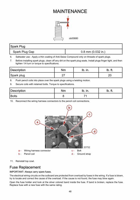
MAINTENANCE
48
ob00680
Spark Plug
Spark Plug Gap 0.8 mm (0.032 in.)6. Saltwater use - Apply a thin coating of Anti-Seize Compound only on threads of spark plugs.7. Before installing spark plugs, clean off any dirt on the spark plug seats. Install plugs finger tight, and then
tighten 1/4 turn or torque to specifications.
Description Nm lb. in. lb. ft.
Spark plug 27 208. Push pencil coils into place over the spark plugs using a twisting motion.9. Secure coils with retained bolts. Torque to specifications.
Description Nm lb. in. lb. ft.
Bolts 8 7110. Reconnect the wiring harness connectors to the pencil coil connections.
a
b
d
c
20752a - Wiring harness connectorb - Pencil coil
c - Boltd - Ground strap
11. Reinstall top cowl.
Fuse ReplacementIMPORTANT: Always carry spare fuses.The electrical wiring circuits on the outboard are protected from overload by fuses in the wiring. If a fuse is blown,try to locate and correct the cause of the overload. If the cause is not found, the fuse may blow again.Open the fuse holder and look at the silver colored band inside the fuse. If band is broken, replace the fuse.Replace fuse with a new fuse with the same rating.

MAINTENANCE
49
a b
52
15c
d
e
2020
20
20
f
gh
i
20819a - Good fuseb - Blown fusec - Diagnostics terminal - 2 AMP fused - 14 pin remote control harness/cowl trim
switch/main power relay - 15 AMP fusee - SmartCraft data bus circuit - 5 AMP fuse
f - Electric fuel pump - 20 AMP fuseg - Ignition coils - 20 AMP fuseh - Spare fuse - 20 AMP fusei - Fuel injectors/purge valve/idle air control - 20
AMP fuse
Alternator Drive Belt InspectionInspect the alternator drive belt and have it replaced by an authorized dealer if any of the following conditionsare found:
a
20775a - Alternator drive belt
• Cracks in the back of the belt or in the base of the V grooves.• Excessive wear at the roots of the grooves.• Rubber portion swollen by oil.
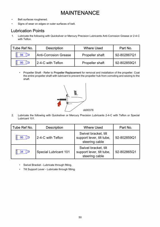
MAINTENANCE
50
• Belt surfaces roughened.• Signs of wear on edges or outer surfaces of belt.
Lubrication Points1. Lubricate the following with Quicksilver or Mercury Precision Lubricants Anti-Corrosion Grease or 2-4-C
with Teflon.
Tube Ref No. Description Where Used Part No.
94 Anti-Corrosion Grease Propeller shaft 92-802867Q1
95 2-4-C with Teflon Propeller shaft 92-802859Q1
• Propeller Shaft - Refer to Propeller Replacement for removal and installation of the propeller. Coatthe entire propeller shaft with lubricant to prevent the propeller hub from corroding and seizing to theshaft.
ob00378
2. Lubricate the following with Quicksilver or Mercury Precision Lubricants 2-4-C with Teflon or SpecialLubricant 101.
Tube Ref No. Description Where Used Part No.
95 2-4-C with TeflonSwivel bracket, tilt
support lever, tilt tube,steering cable
92-802859Q1
34 Special Lubricant 101Swivel bracket, tilt
support lever, tilt tube,steering cable
92-802865Q1
• Swivel Bracket - Lubricate through fitting.• Tilt Support Lever - Lubricate through fitting.

MAINTENANCE
51
b ob00683
a
a - Swivel bracket b - Tilt support lever
• Tilt Tube - Lubricate through fitting.
ob00684
• Steering Cable Grease Fitting (If equipped) - Rotate steering wheel to fully retract the steering cableend into the outboard tilt tube. Lubricate through fitting.
a b
ob00685a - Fitting b - Steering cable end
! WARNINGThe end of the steering cable must be fully retracted into the outboard tilt tube before adding lubricant.Adding lubricant to steering cable when fully extended could cause steering cable to become hydraulicallylocked. A hydraulically locked steering cable will cause loss of steering control, possibly resulting in seriousinjury or death.
3. Lubricate the following with light weight oil.• Steering Link Rod Pivot Points - Lubricate pivot points.
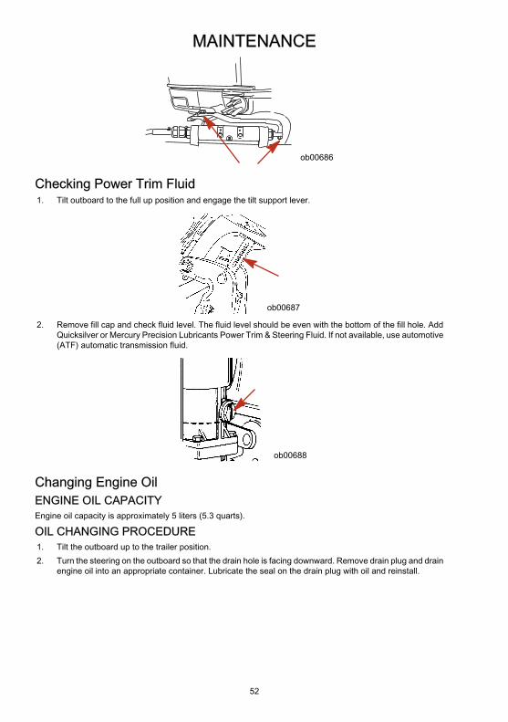
MAINTENANCE
52
ob00686
Checking Power Trim Fluid1. Tilt outboard to the full up position and engage the tilt support lever.
ob00687
2. Remove fill cap and check fluid level. The fluid level should be even with the bottom of the fill hole. AddQuicksilver or Mercury Precision Lubricants Power Trim & Steering Fluid. If not available, use automotive(ATF) automatic transmission fluid.
ob00688
Changing Engine OilENGINE OIL CAPACITYEngine oil capacity is approximately 5 liters (5.3 quarts).
OIL CHANGING PROCEDURE1. Tilt the outboard up to the trailer position.2. Turn the steering on the outboard so that the drain hole is facing downward. Remove drain plug and drain
engine oil into an appropriate container. Lubricate the seal on the drain plug with oil and reinstall.
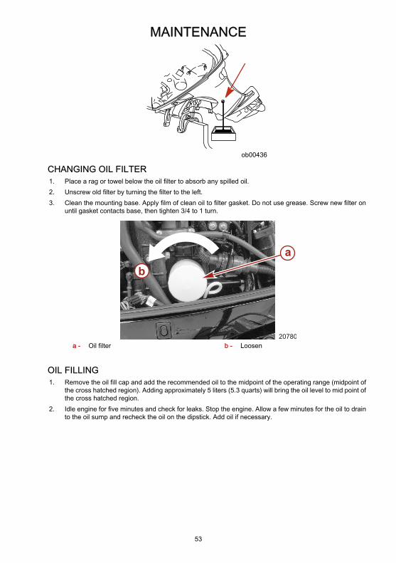
MAINTENANCE
53
ob00436
CHANGING OIL FILTER1. Place a rag or towel below the oil filter to absorb any spilled oil.2. Unscrew old filter by turning the filter to the left.3. Clean the mounting base. Apply film of clean oil to filter gasket. Do not use grease. Screw new filter on
until gasket contacts base, then tighten 3/4 to 1 turn.
ab
20780a - Oil filter b - Loosen
OIL FILLING1. Remove the oil fill cap and add the recommended oil to the midpoint of the operating range (midpoint of
the cross hatched region). Adding approximately 5 liters (5.3 quarts) will bring the oil level to mid point ofthe cross hatched region.
2. Idle engine for five minutes and check for leaks. Stop the engine. Allow a few minutes for the oil to drainto the oil sump and recheck the oil on the dipstick. Add oil if necessary.

MAINTENANCE
54
20714
Gearcase LubricationWhen adding or changing gearcase lubricant, visually check for the presence of water in the lubricant. If wateris present, it may have settled to the bottom and will drain out prior to the lubricant, or it may be mixed with thelubricant, giving it a milky colored appearance. If water is noticed, have the gearcase checked by your dealer.Water in the lubricant may result in premature bearing failure or, in freezing temperatures, will turn to ice anddamage the gearcase.Examine the drained gearcase lubricant for metal particles. A small amount of metal particles indicates normalgear wear. An excessive amount of metal filings or larger particles (chips) may indicate abnormal gear wear andshould be checked by an authorized dealer.
DRAINING GEARCASE1. Place outboard in a vertical operating position.2. Place a drain pan below outboard.3. Remove vent plugs and fill/drain plug and drain lubricant.
a
bob00441
a - Vent plugs b - Fill/drain plug
GEARCASE LUBRICANT CAPACITYGearcase lubricant capacity is approximately 666 ml (22.5 fl. oz.).
GEARCASE LUBRICANT RECOMMENDATIONMercury or Quicksilver Premium or High Performance Gear Lubricant.

MAINTENANCE
55
CHECKING LUBRICANT LEVEL AND FILLING GEARCASE1. Place outboard in a vertical operating position.2. Remove the front vent plug and rear vent plug.3. Remove fill/drain plug. Place lubricant tube into the fill/drain plug hole and add lubricant until it appears
at the front vent hole. At this time install the front vent plug and sealing washer.
a d
ob00442
e
c
b
a - Front vent plugb - Front vent holec - Rear vent hole
d - Rear vent pluge - Fill/drain plug
4. Continue adding lubricant until it appears at the rear vent hole.5. Stop adding lubricant. Install the rear vent plug and sealing washer before removing lubricant tube.6. Remove lubricant tube and reinstall cleaned fill/drain plug and sealing washer.
SUBMERGED OUTBOARDA submerged outboard will require service within a few hours by an authorized dealer once the outboard isrecovered from the water. This immediate attention by a servicing dealer is necessary once the engine is exposedto the atmosphere to minimize internal corrosion damage to the engine.
STORAGE
56
Storage PreparationThe major consideration in preparing your outboard for storage is to protect it from rust, corrosion, and damagecaused by freezing of trapped water.The following storage procedures should be followed to prepare your outboard for out of season storage orprolonged storage (two months or longer).
! CAUTIONNever start or operate your outboard (even momentarily) without water circulating through all the cooling waterintake holes in the gearcase to prevent damage to the water pump (running dry) or overheating of the engine.
FUEL SYSTEMIMPORTANT: Gasoline containing alcohol (ethanol or methanol) can cause a formation of acid during storageand can damage the fuel system. If the gasoline being used contains alcohol, it is advisable to drain as muchof the remaining gasoline as possible from the fuel tank, remote fuel line, and engine fuel system.IMPORTANT: This outboard is equipped with a closed fuel system when the engine is not running. With thisclosed system, fuel within the engine's fuel system, other than the fuel tank, will remain stable during normalstorage periods without the addition of fuel treatment stabilizers.Fill the fuel tank and engine fuel system with treated (stabilized) fuel to help prevent formation of varnish andgum. Proceed with the following instructions.• Portable Fuel Tank - Pour the required amount of Fuel System Treatment and Stabilizer (follow
instructions on container) into fuel tank. Tip fuel tank back and forth to mix stabilizer with the fuel.• Permanently Installed Fuel Tank - Pour the required amount of Fuel System Treatment and Stabilizer
(follow instructions on container) into a separate container and mix with approximately one liter (one quart)of gasoline. Pour this mixture into fuel tank.
Tube Ref No. Description Where Used Part No.
124 Fuel System Treatment& Stabilizer Fuel tank 802875Q1
Protecting External Outboard Components• Touch up any paint nicks. See your dealer for touch-up paint.• Spray Quicksilver or Mercury Precision Lubricants Corrosion Guard on external metal surfaces (except
corrosion control anodes).
Tube Ref No. Description Where Used Part No.
120 Corrosion Guard External metal surfaces 92-802878Q55
Protecting Internal Engine ComponentsIMPORTANT: Refer to Maintenance - Spark Plug Inspection and Replacement for correct procedure forremoving spark plugs.• Remove pencil coils and spark plugs.• Spray approximately 30 ml (1 fl. oz.) of Storage Seal Rust Inhibitor into each spark plug hole.

STORAGE
57
Tube Ref No. Description Where Used Part No.
119 Storage Seal RustInhibitor Spark plug holes 92-802878Q56
• Actuate key/push button start switch to crank the engine through one start cycle, which will distribute thestorage seal throughout the cylinders.
• Reinstall spark plugs and pencil coils.
Gearcase• Drain and refill the gearcase lubricant (refer to Maintenance - Gearcase Lubrication).
Positioning Outboard For StorageStore outboard in an upright (vertical) position to allow water to drain out of outboard.
! CAUTIONIf outboard is stored tilted up in freezing temperature, trapped cooling water or rain water that may haveentered the propeller exhaust outlet in the gearcase could freeze and cause damage to the outboard.
Battery Storage• Follow the battery manufacturer's instructions for storage and recharging.• Remove the battery from the boat and check water level. Recharge if necessary.• Store the battery in a cool, dry place.• Periodically check the water level and recharge the battery during storage.
TROUBLESHOOTING
58
Starter Motor Will Not Crank the EnginePOSSIBLE CAUSES• Lanyard stop switch not in "RUN" position.• Blown 15 AMP fuse. Check 14 pin remote control harness/cowl trim switch/main power relay fuse. Refer
to Maintenance section.• Outboard is not shifted to neutral position.• Weak battery or battery connections are loose or corroded.• Ignition key switch failure.• Wiring or electrical connection faulty.• Starter motor solenoid or slave solenoid failure.
Engine Will Not StartPOSSIBLE CAUSES• Incorrect starting procedure. Refer to Operation section.• Old or contaminated gasoline.• Fuel is not reaching the engine.
• Fuel tank is empty.• Fuel tank vent not open or restricted.• Fuel line is disconnected or kinked.• Fuel filter is obstructed. Refer to Maintenance section.• Fuel pump failure.• Fuel tank filter obstructed.
• Ignition system component failure.• Spark plugs fouled or defective. Refer to Maintenance section.
Engine Runs ErraticallyPOSSIBLE CAUSES• Overheating - Warning horn not working.• Low oil pressure. Check oil level.• Spark plugs fouled or defective. Refer to Maintenance section.• Incorrect setup and adjustments.• Fuel is being restricted to the engine.
a. Engine fuel filter is obstructed. Refer to Maintenance section.b. Fuel tank filter obstructed.c. Stuck anti-siphon valve located on permanently built-in type fuel tanks.d. Fuel line is kinked or pinched.
• Fuel pump failure.• Ignition system component failure.
Performance LossPOSSIBLE CAUSES• Overheating - Warning horn not working.• Low oil pressure. Check oil level.• Throttle not opening fully.

TROUBLESHOOTING
59
• Damaged propeller or improper propeller size.• Incorrect engine timing, adjustment, or setup.• Boat overloaded or load improperly distributed.• Excessive water in bilge.• Boat bottom is dirty or damaged.
Battery Will Not Hold ChargePOSSIBLE CAUSES• Battery connections are loose or corroded.• Low electrolyte level in battery.• Worn out or inefficient battery.• Excessive use of electrical accessories.• Defective rectifier, alternator, or voltage regulator.• Open circuit in the alternator output wire (fused link).

OWNER SERVICE ASSISTANCE
60
Local Repair ServiceAlways return your outboard to your local authorized dealer should the need for service arise. Only he has thefactory trained mechanics, knowledge, special tools, equipment, and genuine parts and accessories to properlyservice your engine should the need occur. He knows your engine best.
Service Away From HomeIf you are away from your local dealer and the need arises for service, contact the nearest authorized dealer.Refer to the Yellow Pages of the telephone directory. If, for any reason, you cannot obtain service, contact thenearest Mercury Marine Service Office.
Parts And Accessories InquiriesAll inquiries concerning genuine replacement parts and accessories should be directed to your local authorizeddealer. The dealer has the necessary information to order parts and accessories for you. When inquiring onparts and accessories, the dealer requires the model and serial number to order the correct parts.
Service AssistanceYour satisfaction with your outboard product is very important to your dealer and to us. If you ever have a problem,question or concern about your outboard product, contact your dealer or any authorized Mercury Marinedealership. If additional assistance is required, take these steps.1. Talk with the dealership's sales manager or service manager. If this has already been done, then contact
the owner of the dealership.2. Should you have a question, concern, or problem that cannot be resolved by your dealership, please
contact Mercury Marine Service Office for assistance. Mercury Marine will work with you and yourdealership to resolve all problems.
The following information will be needed by the service office:• Your name and address• Daytime telephone number• Model and serial number of your outboard• The name and address of your dealership• Nature of problem
Mercury Marine Service OfficesFor assistance, call, fax, or write. Please include your daytime telephone number with mail and faxcorrespondence.
United States
Telephone (920) 929-5040 Mercury MarineW6250 W. Pioneer RoadP.O. Box 1939Fond du Lac, WI 54936-1939
Fax (920) 929-5893
Website www.mercurymarine.com
Canada
Telephone (905) 567-6372 Mercury Marine Ltd.2395 Meadowpine Blvd.Mississauga, Ontario L5N 7W6Canada
Fax (905) 567-8515
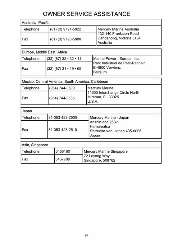
OWNER SERVICE ASSISTANCE
61
Australia, Pacific
Telephone (61) (3) 9791-5822 Mercury Marine Australia132-140 Frankston RoadDandenong, Victoria 3164Australia
Fax (61) (3) 9793-5880
Europe, Middle East, Africa
Telephone (32) (87) 32 • 32 • 11 Marine Power - Europe, Inc.Parc Industriel de Petit-RechainB-4800 Verviers,Belgium
Fax (32) (87) 31 • 19 • 65
Mexico, Central America, South America, Caribbean
Telephone (954) 744-3500 Mercury Marine11650 Interchange Circle NorthMiramar, FL 33025U.S.A.
Fax (954) 744-3535
Japan
Telephone 81-053-423-2500 Mercury Marine - JapanAnshin-cho 283-1HamamatsuShizuoka-ken, Japan 435-0005Japan
Fax 81-053-423-2510
Asia, Singapore
Telephone 5466160 Mercury Marine Singapore72 Loyang WaySingapore, 508762Fax 5467789
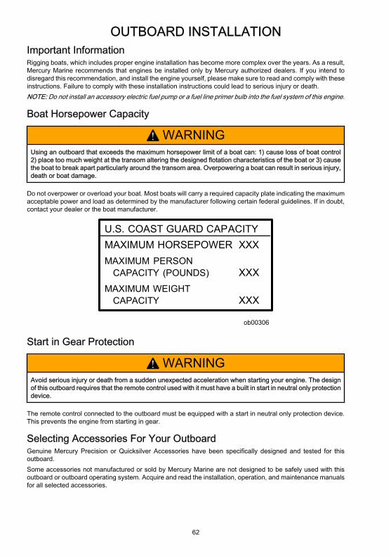
OUTBOARD INSTALLATION
62
Important InformationRigging boats, which includes proper engine installation has become more complex over the years. As a result,Mercury Marine recommends that engines be installed only by Mercury authorized dealers. If you intend todisregard this recommendation, and install the engine yourself, please make sure to read and comply with theseinstructions. Failure to comply with these installation instructions could lead to serious injury or death.NOTE: Do not install an accessory electric fuel pump or a fuel line primer bulb into the fuel system of this engine.
Boat Horsepower Capacity
! WARNINGUsing an outboard that exceeds the maximum horsepower limit of a boat can: 1) cause loss of boat control2) place too much weight at the transom altering the designed flotation characteristics of the boat or 3) causethe boat to break apart particularly around the transom area. Overpowering a boat can result in serious injury,death or boat damage.
Do not overpower or overload your boat. Most boats will carry a required capacity plate indicating the maximumacceptable power and load as determined by the manufacturer following certain federal guidelines. If in doubt,contact your dealer or the boat manufacturer.
U.S. COAST GUARD CAPACITYMAXIMUM HORSEPOWER XXXMAXIMUM PERSON CAPACITY (POUNDS) XXXMAXIMUM WEIGHT CAPACITY XXX
ob00306
Start in Gear Protection
! WARNINGAvoid serious injury or death from a sudden unexpected acceleration when starting your engine. The designof this outboard requires that the remote control used with it must have a built in start in neutral only protectiondevice.
The remote control connected to the outboard must be equipped with a start in neutral only protection device.This prevents the engine from starting in gear.
Selecting Accessories For Your OutboardGenuine Mercury Precision or Quicksilver Accessories have been specifically designed and tested for thisoutboard.Some accessories not manufactured or sold by Mercury Marine are not designed to be safely used with thisoutboard or outboard operating system. Acquire and read the installation, operation, and maintenance manualsfor all selected accessories.
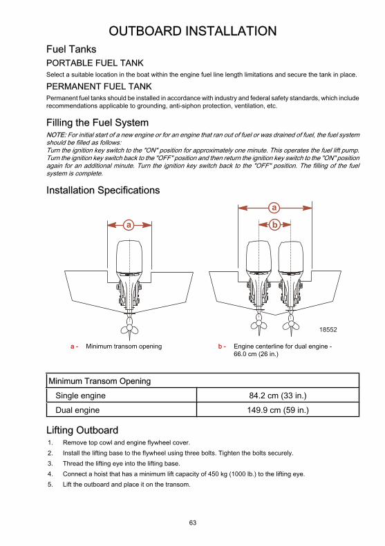
OUTBOARD INSTALLATION
63
Fuel TanksPORTABLE FUEL TANKSelect a suitable location in the boat within the engine fuel line length limitations and secure the tank in place.
PERMANENT FUEL TANKPermanent fuel tanks should be installed in accordance with industry and federal safety standards, which includerecommendations applicable to grounding, anti-siphon protection, ventilation, etc.
Filling the Fuel SystemNOTE: For initial start of a new engine or for an engine that ran out of fuel or was drained of fuel, the fuel systemshould be filled as follows:Turn the ignition key switch to the "ON" position for approximately one minute. This operates the fuel lift pump.Turn the ignition key switch back to the "OFF" position and then return the ignition key switch to the "ON" positionagain for an additional minute. Turn the ignition key switch back to the "OFF" position. The filling of the fuelsystem is complete.
Installation Specifications
a b
a
18552
a - Minimum transom opening b - Engine centerline for dual engine -66.0 cm (26 in.)
Minimum Transom Opening
Single engine 84.2 cm (33 in.)
Dual engine 149.9 cm (59 in.)
Lifting Outboard1. Remove top cowl and engine flywheel cover.2. Install the lifting base to the flywheel using three bolts. Tighten the bolts securely.3. Thread the lifting eye into the lifting base.4. Connect a hoist that has a minimum lift capacity of 450 kg (1000 lb.) to the lifting eye.5. Lift the outboard and place it on the transom.

OUTBOARD INSTALLATION
64
a
b
20854a - Lifting base b - Lifting eye
Flywheel Puller/Lifting Ring 91-895343T02
14869
Removes flywheel from engine. Usedfor lifting powerhead/engine.
Steering Cable - Starboard Side Routed Cable1. Lubricate O-ring seal and entire cable end.
3724
95
Tube Ref No. Description Where Used Part No.
95 2-4-C Marine Lubricantwith Teflon
O-ring seal and entirecable end 92-802859Q1
2. Insert steering cable into tilt tube.
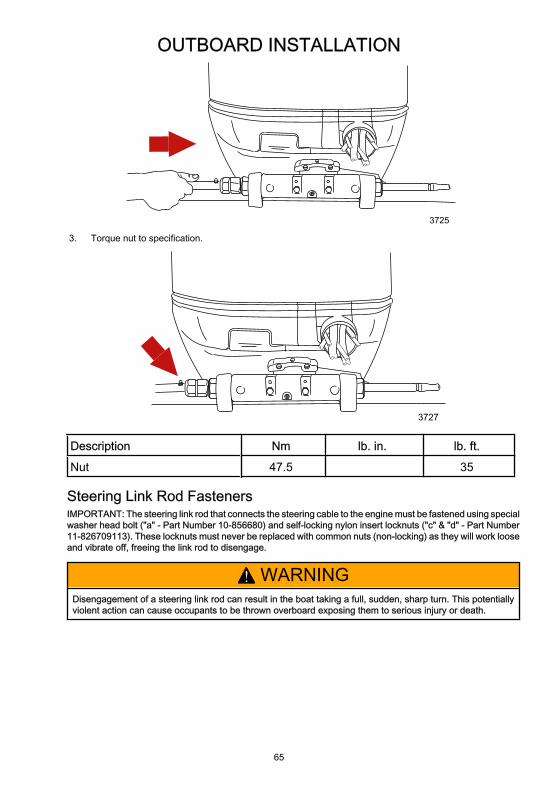
OUTBOARD INSTALLATION
65
3725
3. Torque nut to specification.
3727
Description Nm lb. in. lb. ft.
Nut 47.5 35
Steering Link Rod FastenersIMPORTANT: The steering link rod that connects the steering cable to the engine must be fastened using specialwasher head bolt ("a" - Part Number 10-856680) and self-locking nylon insert locknuts ("c" & "d" - Part Number11-826709113). These locknuts must never be replaced with common nuts (non-locking) as they will work looseand vibrate off, freeing the link rod to disengage.
! WARNINGDisengagement of a steering link rod can result in the boat taking a full, sudden, sharp turn. This potentiallyviolent action can cause occupants to be thrown overboard exposing them to serious injury or death.
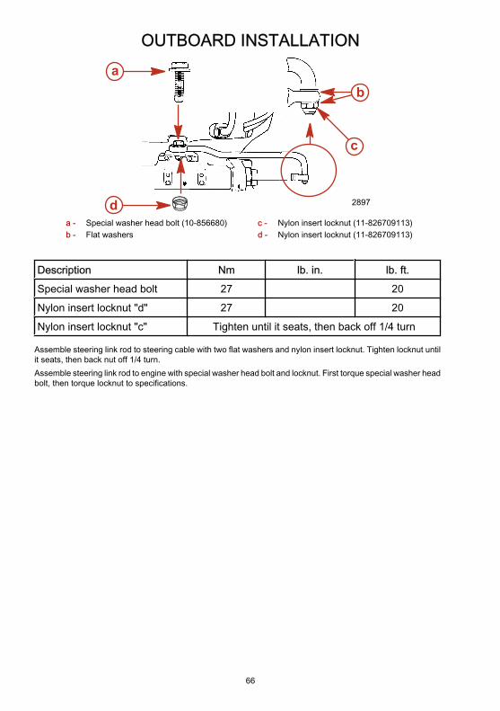
OUTBOARD INSTALLATION
66
2897
ab
c
da - Special washer head bolt (10-856680)b - Flat washers
c - Nylon insert locknut (11-826709113)d - Nylon insert locknut (11-826709113)
Description Nm lb. in. lb. ft.
Special washer head bolt 27 20
Nylon insert locknut "d" 27 20
Nylon insert locknut "c" Tighten until it seats, then back off 1/4 turn
Assemble steering link rod to steering cable with two flat washers and nylon insert locknut. Tighten locknut untilit seats, then back nut off 1/4 turn.Assemble steering link rod to engine with special washer head bolt and locknut. First torque special washer headbolt, then torque locknut to specifications.

OUTBOARD INSTALLATION
67
Determining Recommended Outboard Mounting Height
(20 in.)
(21 in.)
(22 in.)
(23 in.)
(24 in.)
(25 in.)
(19 in.)
10 20 30 40 50 60 70 80
63.5 cm
60.9 cm
58.4 cm
56.0 cm
53.3 cm
50.8 cm
48.2 cm
e
a
c
d
b
f
e
18562
a - The solid line is recommended todetermine the outboard mounting height.
b - The broken lines represent the extremesof known successful outboard mountingheight dimensions.
c - This line may be preferred to determineoutboard mounting height dimension, if
d - This line may be preferred to determineoutboard mounting height dimension for dualoutboard installation.
e - Outboard mounting height (height ofoutboard mounting brackets from bottom ofboat transom). For heights over

OUTBOARD INSTALLATION
68
maximum speed is the only objective. 56.0 cm (22 in.), a propeller that is designedfor surfacing operation is usually preferred.
f - Maximum boat speed (MPH) anticipated
NOTICE
1. The outboard should be mounted high enough on the transom so the exhaustrelief hole will stay at least 25.4 mm (1 in.) above the waterline when the engineis running at idle speed. Having the exhaust relief hole above the waterline willprevent exhaust restrictions. Exhaust restrictions will result in poor performanceat idle.
2. Add 12.7 cm (5 in.) for XL models to the listed outboard mounting heights.3. The mounting height of the outboard must not exceed 63.5 cm (25 in.) for L
models, 76 cm (30 in.) for XL models. Mounting the outboard higher may causedamage to the gearcase components.
Increasing the mounting height will usually:• Reduce steering torque• Increase top speed• Increase boat stability• Cause propeller to break loose during planing
Drilling Outboard Mounting HolesIMPORTANT: Before drilling any mounting holes, carefully read Determining Recommended Outboard MountingHeight and install outboard to the nearest recommended mounting height.1. Mark four mounting holes on the transom using the transom drilling fixture.
or69-1
a
a
b
ca - Drill guide holesb - Transom drilling fixture
c - Transom centerline

OUTBOARD INSTALLATION
69
Transom Drilling Fixture 91-98234A2
5489
Aids in engine installation by acting asa template for engine mounting holes.
2. Drill four 13.5 mm (17/32 in.) mounting holes.
3973
Fastening the Outboard to the TransomMOUNTING BOLTS
Outboard Transom Mounting Hardware - Supplied with Outboard
Part Number Part Name Description
10-67755-1 Transom bolt 1/2-20 x 4.50 in. long (2.25 in. thread)
11-826711-17 Nylon insert locknut 1/2-20
12-28421 Washer - Inner 0.516 in. ID x 1.50 in. OD
12-54012 Washer - Outer 0.53 in. ID x 0.87 in. OD
Available Transom Mounting Bolts
Part Number Part Name Description
10-67755005 Transom bolt 1/2-20 x 2.50 in. long (1.25 in. thread)
10-67755006 Transom bolt 1/2-20 x 3.50 in. long (1.25 in. thread)
10-814259 Transom bolt 1/2-20 x 4.00 in. long (2.25 in. thread)
10-67755-1 Transom bolt 1/2-20 x 4.50 in. long (2.25 in. thread)
10-67755-2 Transom bolt 1/2-20 x 6.50 in. long (2.75 in. thread)

OUTBOARD INSTALLATION
70
CHECKING BOAT TRANSOM CONSTRUCTIONIMPORTANT: Determine the strength of the boat transom. The outboard mounting locknuts and bolts shouldbe able to hold 75 Nm (55 lb. ft.) of torque without the boat transom yielding or cracking. If the boat transomyields or cracks under this torque, the construction of the transom may not be adequate. The boat transom mustbe strengthened or the load carrying area increased.
18961
ab
a - Transom yielding under bolt torque b - Transom cracking under bolt torque
When first determining transom strength, use a dial torque wrench. If the bolt or nut continues to turn withoutthe torque reading on the dial increasing, it is an indication that the transom is yielding. The load area can beincreased by using a larger washer or a transom reinforcement plate.NOTE: The inside holes on the transom reinforcement plate are for the lower transom bolts and the outsideholes are for the upper transom bolts.
a
b
20860a - Large transom washer b - Transom reinforcement plate
Description Part Number
Large transom washer 67-896392
Transom reinforcement plate 67-896305
1. Apply marine sealer to shanks of bolts, not the threads.2. Fasten the outboard with the correct mounting hardware. Tighten locknuts to the specified torque.NOTE: For more accurate torque, whenever possible turn/tighten the mounting locknuts rather than turning themounting bolts.

OUTBOARD INSTALLATION
71
3729
a
b
c
d
e
a - Flat washer (4)b - 1/2 in. diameter bolt (4)c - Shank of bolt
d - Locknut (4)e - Flat washer (4)
Description Nm lb. in. lb. ft.
Outboard mounting locknuts and bolts 75 55
Electrical, Fuel Hose, and Control Cables
FRONT COWL GROMMETInstallationIMPORTANT: Sufficient slack must exist in wiring harnesses, battery cables, and hoses, that are routed betweenthe rubber grommet and engine attachment points, to relieve stress and prevent hoses from being kinked orpinched.1. Pull up the cowl seal. Remove the access cover from the bottom cowl.

OUTBOARD INSTALLATION
72
a
bf
c
d e
g
20792
hi
ja - Access coverb - Front grommetc - Fuel hose openingd - Remote wiring harness openinge - Throttle cable opening
f - Battery cable openingg - Speedometer tube openingh - SmartCraft harness or additional harness
openingi - Shift cable openingj - Cable tie
2. Route the hoses, wiring, and cables through the correct opening in the front grommet as shown.3. Reinstall the access cover with two bolts. Reattach the cowl seal.4. Attach a cable tie around the outside diameter of the front grommet.
a
20794a - Cable tie
REMOTE WIRING HARNESSRoute the remote 14 pin boat harness through the front grommet. Connect the remote harness to the 14 pinconnector on the engine harness.

OUTBOARD INSTALLATION
73
a
b
20791a - 14 pin connector b - Remote 14 pin boat harness
SMARTCRAFT HARNESS CONNECTIONIf SmartCraft gauges are being used with the outboard, route the SmartCraft wiring harness through the frontgrommet and connect it to the SmartCraft harness connector on the engine.
a
20895a - SmartCraft harness connector

OUTBOARD INSTALLATION
74
BATTERY CABLE CONNECTIONSSingle Outboard
(+)
(-)
a
bc
or86a - Red sleeve - positive (+)b - Black sleeve - negative (–)
c - Cranking battery
Dual OutboardsConnect a common ground cable (wire size same as engine battery cables) between negative (–) terminals onstarting batteries.
(-)
(-)
a
a
b
b
cd
d
or87a - Red sleeve - positive (+)b - Black sleeve - negative (–)
c - Ground cabled - Cranking battery

OUTBOARD INSTALLATION
75
FUEL HOSE CONNECTIONFasten remote fuel hose to fitting with hose clamp.
Fuel Hose SizeMinimum fuel hose inside diameter (ID) is 8 mm (5/16 in.) with separate fuel hose/fuel tank pickup for eachengine.
a
b
20804a - Hose clamp b - Fuel hose
SHIFT CABLE INSTALLATIONInstall cables into the remote control following the instructions provided with the remote control.NOTE: Install the shift cable to the engine first. The shift cable is the first cable to move when the remote controlhandle is moved out of neutral.1. Remove the access cover from the bottom cowl.NOTE: The high pressure fuel hose can be moved out of the way for additional access.
a
b
20893a - Access cover b - High pressure fuel hose
2. Position the shift mechanism into the neutral position.
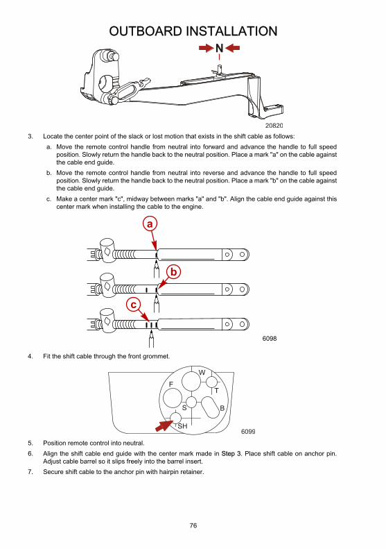
OUTBOARD INSTALLATION
76
N
208203. Locate the center point of the slack or lost motion that exists in the shift cable as follows:
a. Move the remote control handle from neutral into forward and advance the handle to full speedposition. Slowly return the handle back to the neutral position. Place a mark "a" on the cable againstthe cable end guide.
b. Move the remote control handle from neutral into reverse and advance the handle to full speedposition. Slowly return the handle back to the neutral position. Place a mark "b" on the cable againstthe cable end guide.
c. Make a center mark "c", midway between marks "a" and "b". Align the cable end guide against thiscenter mark when installing the cable to the engine.
6098
b
c
a
4. Fit the shift cable through the front grommet.
6099
5. Position remote control into neutral.6. Align the shift cable end guide with the center mark made in Step 3. Place shift cable on anchor pin.
Adjust cable barrel so it slips freely into the barrel insert.7. Secure shift cable to the anchor pin with hairpin retainer.

OUTBOARD INSTALLATION
77
a
b d
f
e
20824
c
a - Center markb - Barrel insertc - Cable barrel
d - Hairpin retainere - Anchor pinf - Barrel holder
8. Lock barrel in place with cable latch.
a
20825a - Cable latch
9. Check shift cable adjustments as follows:a. Shift remote control into forward. The propeller shaft should be locked in gear. If not, adjust the barrel
closer to the cable end.b. Shift remote control into neutral. The propeller shaft should turn freely without drag. If not, adjust the
barrel away from the cable end. Repeat steps a and b.c. Shift remote control into reverse while turning propeller. The propeller shaft should be locked in gear.
If not, adjust the barrel away from the cable end. Repeat steps a through c.d. Shift remote control back to neutral. The propeller shaft should turn freely without drag. If not, adjust
the barrel closer to the cable end. Repeat steps a through d.10. If the throttle cable is already installed, place the high pressure fuel hose back into the hose retainers.
Reinstall the access cover.

OUTBOARD INSTALLATION
78
ba a
20905a - Fuel hose retainer b - High pressure fuel hose
THROTTLE CABLE INSTALLATIONInstall cables into the remote control following the instructions provided with the remote control.1. Remove the access cover from the bottom cowl.NOTE: The high pressure fuel hose can be moved out of the way for additional access.
a
b
20893a - Access cover b - High pressure fuel hose
2. Position remote control into neutral.
N
ob00351
3. Install the throttle cable to the throttle arm with the retainer clip.4. Adjust the cable barrel so that the installed throttle cable will hold the throttle arm against the idle stop.5. Fit the throttle cable through the front grommet.6. Place cable barrel into barrel retainer.
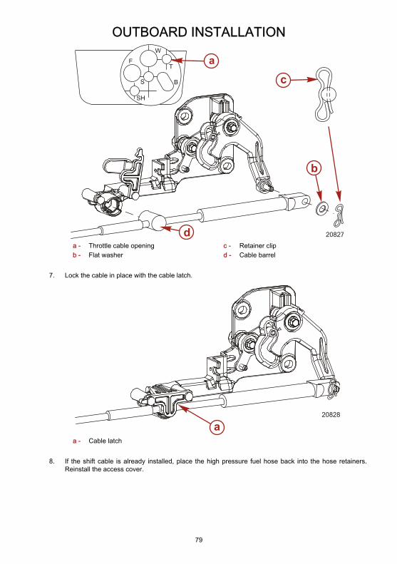
OUTBOARD INSTALLATION
79
a
d
b
c
20827
a - Throttle cable openingb - Flat washer
c - Retainer clipd - Cable barrel
7. Lock the cable in place with the cable latch.
20828
aa - Cable latch
8. If the shift cable is already installed, place the high pressure fuel hose back into the hose retainers.Reinstall the access cover.

OUTBOARD INSTALLATION
80
ba a
20905a - Fuel hose retainer b - High pressure fuel hose
Trim In Pin
! WARNINGAvoid possible serious injury or death. Adjust outboard to an intermediate trim position as soon as boat is onplane to avoid possible ejection due to boat spin out. Do not attempt to turn boat when on plane if outboardis trimmed extremely in or down and there is a pull on the steering wheel.
Some boats, particularly some bass boats, are built with a greater than normal transom angle, which will allowthe outboard to be trimmed further in or under. This greater trim under capability is desirable to improveacceleration, reduce the angle and time spent in a bow high boat during planing off, and in some cases, may benecessary to plane off a boat with aft live wells, given the variety of available propellers and height range ofengine installations.However, once on plane, the engine should be trimmed to a more intermediate position to avoid a bow-downplaning condition called plowing. Plowing can cause bow steering or over steering and inefficiently consumeshorsepower.
a
or116a - Tilt pin (not included with engine)
Stainless Steel Tilt Pin 17-49930A 1
2749
Limits the down trim angle of the powertrim equipped engines, or aids indetermining the trim out angle on non-power trim engines.

OUTBOARD INSTALLATION
81
The owner may decide to limit the trim in. This can be accomplished by purchasing a stainless steel tilt pin fromyour dealer and insert it in whatever adjustment hole in the transom brackets is desired. A non-stainless steelshipping bolt should not be used in this application other than on a temporary basis.