Deck Overhang Design - Minnesota Department of ... · • Detailed updates –deck overhang design...
30
Deck Overhang Design Braden Cyr | Bridge Engineer May 17, 2017 Bridge Office | mndot.gov/bridge
-
Upload
hoangxuyen -
Category
Documents
-
view
218 -
download
1
Transcript of Deck Overhang Design - Minnesota Department of ... · • Detailed updates –deck overhang design...

Deck Overhang Design
Braden Cyr | Bridge Engineer
May 17, 2017
Bridge Office | mndot.gov/bridge

Topics Covered
• General overview
• Old practice
• New practice (Memo 2017‐01) and reason for changes
• http://www.dot.state.mn.us/bridge/lrfd.html
• Impacts on design
• Detailed updates – deck overhang design
5/17/2017 2Bridge Office | mndot.gov/bridge
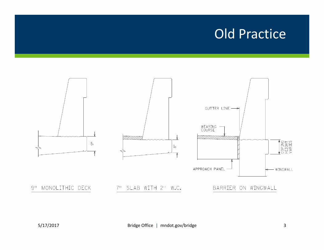
Old Practice
5/17/2017 Bridge Office | mndot.gov/bridge 3

Reason for Change
5/17/2017 4
Discontinuous coping line
Bridge Office | mndot.gov/bridge
A
A

Reason for Change
• Provide consistency and clarity for edge of deck (EOD) thickness and coping height
• Slab with wearing course – old practice results in discontinuous coping line
• Old practice – unclear what to use for EOD thickness for thick decks
5/17/2017 5Bridge Office | mndot.gov/bridge
Section A‐A

New Practice
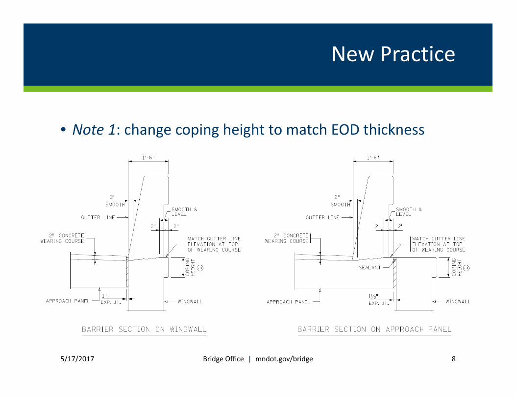
• Slope top of deck to match gutterline elevation at EOD
• Note 1: match EOD thickness with deck thickness per BDM Tables 9.2.1.1 and 9.2.1.2
• No change to monolithic slab
5/17/2017 6Bridge Office | mndot.gov/bridge
Level

New Practice
• Provide EOD thickness equal to deck thickness specified in BDM Tables 9.2.1.1 (right) and 9.2.1.2 (similar)
• Exception: repair with deck thickness < 9” –provide 9” EOD thickness
5/17/2017 7BDM Table 9.2.1.1
Bridge Office | mndot.gov/bridge
New Practice
• Note 1: change coping height to match EOD thickness
5/17/2017 8Bridge Office | mndot.gov/bridge

Impacts on Design
• Changes to Memo to Designers 2016‐01
• Deck surface no longer level beneath barrier
• New guidance for deck overhang design
• Critical section reduced
• Some instances require modifications to BDM Tables 9.2.1.1, 9.2.1.2
5/17/2017 9Bridge Office | mndot.gov/bridge

5/17/2017 10
Typical design/meets assumptions of BDM Tables 9.2.1.1, 9.2.1.2?
NO
YES
Memo 2017‐01 Special Design
Interior barrier region? YES
NO
Gutter line inside the edge of fascia beam flange?
YES
NO
54” Type S Barrier? YES
NO
42” Type S Barrier? YES
NO
36” Type S Barrier? YES
9” Monolithic or 7” + 2” W. Course?
Deck w/ W.C. supported by steel beams
w/ spc. > 12’?
Memo 2017-01 Mods (bullet pt. 3)YES
YES
NO
NO
Memo 2017-01 Mods (bullet pt. 1)
Memo 2017-01 Mods (bullet pt. 2)
Use BDM deck R/F (Tables 9.2.1.1, 9.2.1.2)
Use BDM deck R/F (Tables 9.2.1.1, 9.2.1.2)
Use BDM deck R/F (Tables 9.2.1.1, 9.2.1.2)
Use BDM deck R/F (Tables 9.2.1.1, 9.2.1.2)

General BDM Design Table Assumptions
• Overhang width 40% beam spacing
• fc’ = 4 ksi, fy = 60 ksi
• Typical steel or concrete beams used
• Live load moments taken from AASHTO A4.1‐1
• Clear cover of 3” top R/F and 1” bottom R/F
• Yield line occurs in barrier
5/17/2017 Bridge Office | mndot.gov/bridge 11

5/17/2017 12
Typical design/meets assumptions of BDM Tables 9.2.1.1, 9.2.1.2?
NO
YES
Memo 2017‐01 Special Design
Interior barrier region? YES
NO
Gutter line inside the edge of fascia beam flange?
YES
NO
54” Type S Barrier? YES
NO
42” Type S Barrier? YES
NO
36” Type S Barrier? YES
9” Monolithic or 7” + 2” W. Course?
Deck w/ W.C. supported by steel beams
w/ spc. > 12’?
Memo 2017-01 Mods (bullet pt. 3)YES
YES
NO
NO
Memo 2017-01 Mods (bullet pt. 1)
Memo 2017-01 Mods (bullet pt. 2)
Use BDM deck R/F (Tables 9.2.1.1, 9.2.1.2)
Use BDM deck R/F (Tables 9.2.1.1, 9.2.1.2)
Use BDM deck R/F (Tables 9.2.1.1, 9.2.1.2)
Use BDM deck R/F (Tables 9.2.1.1, 9.2.1.2)

Special Design
• Adjusted NCHRP 350 TL‐4 collision load, Ft, to account for varying barrier heights and heights of load application
• Used min , per BDM section 9.2.1
• Adjusted collision loads, Fcadj and Mcadj, given in Table 1 of memo:
5/17/2017 13Bridge Office | mndot.gov/bridge

Interior vs. Exterior Regions
• Interior region ‐ continuous longitudinal R/F
BDM Figure 13.3.1.1
• Exterior region – barrier R/F is discontinuous (i.e. at joints or end of bridge)
BDM Figure 13.3.1.1
5/17/2017 Bridge Office | mndot.gov/bridge 14

Load Distribution
Interior region: 2
5/17/2017 15
Exterior region:
Bridge Office | mndot.gov/bridge

Special Design
5/17/2017 16
Translate the moment at top of deck to a moment located at deck center:
For monolithic decks:· 0.5 ·
For slabs with wearing course:· 0.5 · )
Bridge Office | mndot.gov/bridge

Special Design Example
• Consider the following case:
• 36” Type S barrier ‐ interior region
• Beam spacing = 9’
• Overhang width = 4’
• 7” deck with 2” wearing course
5/17/2017 17Bridge Office | mndot.gov/bridge

Special Design Example
• Determine if a special design is required:
49 0.44 0.40
• Recall additional assumptions to verify
• Since OH > 40% of beam spacing, must perform special design
• Find adjusted loads in Table 1 of Memo 2017‐01:
5/17/2017 18Bridge Office | mndot.gov/bridge

Special Design Example
• Use the equations provided in the memo:. · /. /
2.54
3.7 /
For deck with a 7” structural slab plus 2” wearing course:
· 0.5 ·
How to find tstr slab?
5/17/2017 19Bridge Office | mndot.gov/bridge

Special Design Example
5/17/2017 20
• From earlier in the memo, for a 7” slab with 2” wearing course, EOD thickness (and coping thickness) must be 9”
• Using the new geometry for the edge of deck, the critical section depth (i.e. tstr slab) is found to be 8.45”
• Side note: old geometry would have given tstr slabof 8.69” at this location
Bridge Office | mndot.gov/bridge

Special Design Example
• Given the value of tstr slab, we can continue with the equations in the memo:
· 0.5 · 3.7 · 2.54 0.5 ·8.4512 /
10.7 · /
• Summary:
• Fcdes = 3.7 k/ft
• Mcdes = 10.7 k·ft/ft
• Use these design values to determine the reinforcement required at the critical section (see BDM section 9.3 for an example)
5/17/2017 21Bridge Office | mndot.gov/bridge

5/17/2017 22
Typical design/meets assumptions of BDM Tables 9.2.1.1, 9.2.1.2?
NO
YES
Memo 2017‐01 Special Design
Interior barrier region? YES
NO
Gutter line inside the edge of fascia beam flange?
YES
NO
54” Type S Barrier? YES
NO
42” Type S Barrier? YES
NO
36” Type S Barrier? YES
9” Monolithic or 7” + 2” W. Course?
Deck w/ W.C. supported by steel beams
w/ spc. > 12’?
Memo 2017-01 Mods (bullet pt. 3)YES
YES
NO
NO
Memo 2017-01 Mods (bullet pt. 1)
Memo 2017-01 Mods (bullet pt. 2)
Use BDM deck R/F (Tables 9.2.1.1, 9.2.1.2)
Use BDM deck R/F (Tables 9.2.1.1, 9.2.1.2)
Use BDM deck R/F (Tables 9.2.1.1, 9.2.1.2)
Use BDM deck R/F (Tables 9.2.1.1, 9.2.1.2)

Gutter Line and Flange Edge
• If overlap exists, can use BDM Design Tables
• If no overlap, see memo design criteria
5/17/2017 Bridge Office | mndot.gov/bridge 23

5/17/2017 24
Typical design/meets assumptions of BDM Tables 9.2.1.1, 9.2.1.2?
NO
YES
Memo 2017‐01 Special Design
Interior barrier region? YES
NO
Gutter line inside the edge of fascia beam flange?
YES
NO
54” Type S Barrier? YES
NO
42” Type S Barrier? YES
NO
36” Type S Barrier? YES
9” Monolithic or 7” + 2” W. Course?
Deck w/ W.C. supported by steel beams
w/ spc. > 12’?
Memo 2017-01 Mods (bullet pt. 3)YES
YES
NO
NO
Memo 2017-01 Mods (bullet pt. 1)
Memo 2017-01 Mods (bullet pt. 2)
Use BDM deck R/F (Tables 9.2.1.1, 9.2.1.2)
Use BDM deck R/F (Tables 9.2.1.1, 9.2.1.2)
Use BDM deck R/F (Tables 9.2.1.1, 9.2.1.2)
Use BDM deck R/F (Tables 9.2.1.1, 9.2.1.2)

5/17/2017 25
Typical design/meets assumptions of BDM Tables 9.2.1.1, 9.2.1.2?
NO
YES
Memo 2017‐01 Special Design
Interior barrier region? YES
NO
Gutter line inside the edge of fascia beam flange?
YES
NO
54” Type S Barrier? YES
NO
42” Type S Barrier? YES
NO
36” Type S Barrier? YES
9” Monolithic or 7” + 2” W. Course?
Deck w/ W.C. supported by steel beams
w/ spc. > 12’?
Memo 2017-01 Mods (bullet pt. 3)YES
YES
NO
NO
Memo 2017-01 Mods (bullet pt. 1)
Memo 2017-01 Mods (bullet pt. 2)
Use BDM deck R/F (Tables 9.2.1.1, 9.2.1.2)
Use BDM deck R/F (Tables 9.2.1.1, 9.2.1.2)
Use BDM deck R/F (Tables 9.2.1.1, 9.2.1.2)
Use BDM deck R/F (Tables 9.2.1.1, 9.2.1.2)

5/17/2017 26
Typical design/meets assumptions of BDM Tables 9.2.1.1, 9.2.1.2?
NO
YES
Memo 2017‐01 Special Design
Interior barrier region? YES
NO
Gutter line inside the edge of fascia beam flange?
YES
NO
54” Type S Barrier? YES
NO
42” Type S Barrier? YES
NO
36” Type S Barrier? YES
9” Monolithic or 7” + 2” W. Course?
Deck w/ W.C. supported by steel beams
w/ spc. > 12’?
Memo 2017-01 Mods (bullet pt. 3)YES
YES
NO
NO
Memo 2017-01 Mods (bullet pt. 1)
Memo 2017-01 Mods (bullet pt. 2)
Use BDM deck R/F (Tables 9.2.1.1, 9.2.1.2)
Use BDM deck R/F (Tables 9.2.1.1, 9.2.1.2)
Use BDM deck R/F (Tables 9.2.1.1, 9.2.1.2)
Use BDM deck R/F (Tables 9.2.1.1, 9.2.1.2)
Not in Memo

42” Barrier Modifications
• Include 180° hooks on top transverse bars minimum of 9’ from joint
• Splice hooks to main transverse deck bars (match sizing)
• Provide hooked transverse bars that run from EOD to EOD
• Applicability• 9” monolithic slab
• 7” deck with 2” wearing course
5/17/2017 Bridge Office | mndot.gov/bridge 27

5/17/2017 28
Typical design/meets assumptions of BDM Tables 9.2.1.1, 9.2.1.2?
NO
YES
Memo 2017‐01 Special Design
Interior barrier region? YES
NO
Gutter line inside the edge of fascia beam flange?
YES
NO
54” Type S Barrier? YES
NO
42” Type S Barrier? YES
NO
36” Type S Barrier? YES
9” Monolithic or 7” + 2” W. Course?
Deck w/ W.C. supported by steel beams
w/ spc. > 12’?
Memo 2017-01 Mods (bullet pt. 3)YES
YES
NO
NO
Memo 2017-01 Mods (bullet pt. 1)
Memo 2017-01 Mods (bullet pt. 2)
Use BDM deck R/F (Tables 9.2.1.1, 9.2.1.2)
Use BDM deck R/F (Tables 9.2.1.1, 9.2.1.2)
Use BDM deck R/F (Tables 9.2.1.1, 9.2.1.2)
Use BDM deck R/F (Tables 9.2.1.1, 9.2.1.2)

36” Barrier Modifications
• Deck w/ W.C. supported by steel beams spaced > 12’
• Provide top transverse standard 180° hooked #5 bars at 6” spacing for a minimum of 8’ from joint for EOD (#5 because #6 won’t fit)
• Lap these hooks to the top #6 transverse bars (at 6”, from Table 9.2.1.2)
• All other cases
• Provide #5 bars at 5” spacing or As = 0.74 in /ft for top transverse bars for a minimum of 8’ from joint
• Include 180° standard hooks on the EOD ends of these #5 bars
• Splice hooks to main transverse deck bars
• Provide hooked transverse bars that run from EOD to EOD
5/17/2017 Bridge Office | mndot.gov/bridge 29