Debris/Ice/TPS Assessment and Integrated Photographic ... · Debris/Ice/TPS Assessment and...
148
Debris/Ice/TPS Assessment and Integrated Photographic Analysis of Shuttle Mission STS-75 Jill D. Lin Technical Memorandum 111472 April 1996 https://ntrs.nasa.gov/search.jsp?R=19960022783 2019-03-12T08:30:12+00:00Z
Transcript of Debris/Ice/TPS Assessment and Integrated Photographic ... · Debris/Ice/TPS Assessment and...

Debris/Ice/TPS Assessment and
Integrated Photographic Analysis
of Shuttle Mission STS-75
Jill D. Lin
Technical Memorandum 111472 April 1996
https://ntrs.nasa.gov/search.jsp?R=19960022783 2019-03-12T08:30:12+00:00Z

/
Debris/Ice/TPS Assessment and
Integrated Photographic Analysisof Shuttle Mission STS-7 5
Jill D. Lin
Vehicle Engineering�Mechanical System Division/ET-SRB Branch,
Kennedy Space Center, Florida
Technical Memorandum 111472 April 1996


DEBRIS/ICE/TPS ASSESSMENTAND
INTEGRATED PHOTOGRAPHIC ANALYSISOF
SHUTTLE MISSION STS-75
22 February 1996
Contributions By:
NASA, Lockheed-Martin, Rockwell, and Thiokol Members of theDebris/lce/TPS and Photographic Analysis Teams
Prepared By:
- % -Jill D. Lin
Shuttle Ice/Debris SystemsNASA/KSC/TV-MSD-7
Approved:
d James G. TatumChief, ET/SRB Mech/TPS SystemsNASA/KSC/TV-MSD-7
S_hh__nisksyslem s
NASA/KSC/TV-MSD-7


TABLE OF CONTENTS
TABLE OF CONTENTS ...................................................................................... I
TABLE OF FIGURES ........................................................................................ II
TABLE OF PHOTOS ........................................................................................ III
FOREWORD ..................................................................................................... IV
1.0 SUMMARY .................................................................................................... 2
2.0 PRE-LAUNCH BRIEFING ........................................................................... 4
3.0 LAUNCH ........................................................................................................ 53.1 PRE-LAUNCH SSV/PAD DEBRIS INSPECTION ....................... : ................. 53.2 FINAL INSPECTION ...................................................................................... 53.2.1 ORBITER ..................................................................................................... 53.2.2 SOLID ROCKET BOOSTERS ..................................................................... 53.2.3 EXTERNAL TANK ...................................................................................... 53.2.4 FACILITY .................................................................................................... 6
4.0 POST LAUNCH PAD DEBRIS INSPECTION ......................................... 12
5.0 FILM REVIEW ........................................................................................... 145.1 LAUNCH FILM AND VIDEO SUMMARY ................................................. 145.2 ON-ORBIT FILM AND VIDEO SUMMARY ............................................... 185.3 LANDING FILM AND VIDEO SUMMARY ................................................ 23
6.0 SRB POST FLIGHT/RETRIEVAL DEBRIS ASSESSMENT .................. 246.1 RH SOLID ROCKET BOOSTER DEBRIS INSPECTION ............................ 246.2 LH SOLID ROCKET BOOSTER DEBRIS INSPECTION ............................ 29
7.0 ORBITER POST LANDING DEBRIS ASSESSMENT ............................ 35
8.0 DEBRIS SAMPLE LAB REPORTS ........................................................... 538.1 ORBITER WINDOWS .................................................................................. 538.2 ORGANIC ANALYSIS ................................................................................. 538.3 STS-72 PRELAUNCH ORGANIC ANALYSIS ............................................ 538.4 NEW FINDINGS ........................................................................................... 53
9.0 POST LAUNCH ANOMALIES .................................................................. 579.1 LAUNCH PAD/SHUTTLE LANDING FACILITY ....................................... 579.2 SOLID ROCKET BOOSTERS ...................................................................... 579.3 EXTERNAL TANK ....................................................................................... 579.4 ORBITER ...................................................................................................... 57APPENDIX A. JSC PHOTOGRAPHIC ANALYSIS SUMMARY ........................ AAPPENDIX B. MSFC PHOTOGRAPHIC ANALYSIS SUMMARY .................... B
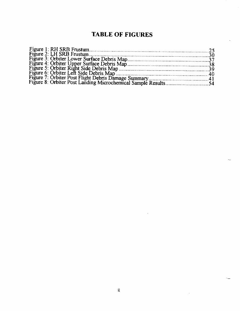
TABLE OF FIGURES
Figure 1 RH SRB Frustum ..................................... 25Figure 2: LH SRB Frustum ..................................... iiiiiiiii'i ..... i .............................. 30_Figure 3: Orbiter Lower Surface Debris Map ................... 1.11111.11111111111111111111111111111137Figure 4: Orbiter Upper Surface Debris Map ......................................................... 38Figure 5: Orbiter Right Side Debris Map ............................................................... 39Figure 6: Orbiter Left Side Debris Map ................................................................. 40Figure 7: Orbiter Post Flight Debris Damage Summa]-y .......................................... 41Figure 8: Orbiter Post Landing Microchemlcal Sample Results .............................. 54

TABLE OF PHOTOS
PhotoPhotoPhotoPhotoPhotoPhotoPhotoPhotoPhotoPhotoPhotoPhotoPhotoPhotoPhotoPhotoPhotoPhotoPhotoPhotoPhotoPhotoPhotoPhotoPhotoPhotoPhotoPhotoPhotoPhotoPhoto
1: Launch of Shuttle Mission STS-75 .......................................................... 12:STS-75 Cryoloaded for Launch ............................................................... 73:ET-76 Cryoloaded for Launch ................................................................. 84: Overall View of SSME s ......................................................................... 95: Sodium Hydroxide Residue on GUCP ................................................... 106: ET/ORB LH2 Umbilical ........................................................................ 117: HDP #5 Stud Hang-Up .......................................................................... 138: GSE Tile Shim ...................................................................................... 169: HDP #5 Stud Hang-Up .... :: .................................................................... 1710: Loose Lightning Contact _trip .............................................................. 1911" LH2 ET/ORB Umbilical After Separation ............................. ................ 2012: ET Separation fi'om Orbiter .................................................................. 2113: Intertank Flange Closeout Divots .......................................................... 2214: RH Frustum .......................................................................................... 2615: RH Forward Skirt ................................................................................. 2716: RH Aft Booster/Aft Skirt ..................................................................... 2817: LH Frustum .......................................................................................... 3118: LH Forward Skirt ................................................................................. 3219: LH Aft Booster/Aft Skirt ..................................................................... 3320: Stud Holes #5 and #6 ............................................................................ 3421: Overall View of Orbiter Left Side ......................................................... 4222: Overall View of Orbiter Right Side ....................................................... 4323: Base Heat Shield/SSME's .................................................................... 4424: Lower Surface Tile Damage ................................................................. 4525:LH2 ET/ORB Umbilical ....................................................................... 4626:EO-2 Debris Container Iris ................................................................... 4727:LO2 ET/ORB Umbilical ....................................................................... 4828: Flipper Door #15 .................................................................................. 4929: Pa_cload Bay Door Discoloration ........................................................... 5030: Orbiter Windows .................................................................................. 5131: Runway Light Damage ......................................................................... 52
iii
FOREWORD
The Debris Team has developed and implemented measures to control damage from debris in theShuttle operational environment and to make the control measures a part of routine launch flows.These measures include engineering surveillance during vehicle processing and closeoutoperations, facility and flight hardware inspections before and after launch, and photographicanalysis of mission events.
Photographic analyses of mission imagery from launch, 0n-orbit, and landing provide significantdata in verifying proper operation of systems and evaluating anomalies. In addition to theKennedy Space Center Photo/Video Analysis, reports from Johnson Space Center and MarshallSpace Flight Center are also included in this document to provide an integrated assessment of themission.
iv

Photo I: Launch of Shutlle Mission STS-75
I


1.0 SUMMARY
A pre-launch debris inspection of the launch pad and Shuttle vehicle was performed on 21February 1996. The detailed walkdown of Pad 39B and MLP-3 also included the primary flightelements OV-102 Columbia (19th flight), ET-76 (LWT 69), and BI-078 SRB's. There were nosignificant vehicle or pad anomalies.
The vehicle was cryoloaded for flight on 22 February 1996. There were no Launch CommitCriteria (LCC), OMRS, or NSTS-08303 criteria violations. No IPR's were taken. No acreageicing or frost conditions were expected due to the mid-afternoon launch time. There were no
ice/frost conditions or protuberance icing conditions outside of the established data base.
After the 3:18 p.m. (local) launch on 22 February 1996, a debris walk down of Pad 39B was
performed. No flight hardware or TPS materials were found. Rockwell-Downey reported a 0.20glateral acceleration at littoff. Holddown post #5 stud hole exhibited burrs around the +Z edge, avisual indication of a stud hang-up. All the T-0 umbilicals operated properly. Overall, damage tothe launch pad was minimal.
A total of 129 films and videos were analyzed as part of the post mission data review. No vehicledamage or lost flight hardware was observed that would have affected the mission. SSME ignitionappeared normal.
A stud hang-up occurred on holddown post #5. As the vehicle gained altitude and the LH aft skirtcleared the stud, a semi-circular piece of aluminum from the stud hole wall fell onto the southwestcorner of the HDP shoe and then downward into the haunch area. Two fragments that may havebeen aluminum shavings fell from the stud hole area. No stud hang-ups occurred on any of theother holddown posts. No ordnance fragments or frangible nut pieces fell from any of the otherDCS/stud holes.
Orbiter umbilical camera films showed nominal separation of SRB's from the External Tank andnormal separation of the ET from the Orbiter. The LO2 ET/ORB umbilical TPS was undamaged.All lightning contact strips were intact. Numerous divots and eroded areas were visible on thehorizontal and vertical sections of the cable tray. The LH2 ET/ORB umbilical appeared to be ingood condition with little or no TPS damage. Foam was missing or eroded from the horizontal(clamshell) section of the cable tray and the aft surface of the -Y vertical strut. A thin, metallicobject with straight edges (lightning contact strip) originated from the LH2 ET/ORB umbilicalarea shortly after umbilical separation and drifted in a general -Y-Z direction. Two of the fivelightning contact strips from the LH2 umbilical appeared to be missing. Loss of lightning contactstrips was the subject of a previous IFA.
The Solid Rocket Boosters were inspected at Hanger AF after retrieval. The number of MSA-2debonds on both frustums was less than average.
Orbiter performance as viewed on landing films and videos during final approach, touchdown, androllout was nominal. Drag chute operation was also normal.
A post landing inspection of OV-102 was conducted 9 March 1996 on SLF runway 33 at theKennedy Space Center. The Orbiter TPS sustained a total of 96 hits, of which 17 had a majordimension of 1-inch or larger. Based on these numbers and comparison to statistics from previousmissions of similar configuration, both the total number of hits and the number of hits 1-inch orlarger was less than average.
2

The Orbiter lower surface sustained a total of 55 hits, of which 11 had a major dimension ofl-inch or larger. The largest lower surface tile damage site occurred on the right inboard devon
and measured 5.0-inches long by 1.0-inch wide by 0.75-inch maximum depth. Hits on the fightside along a line from nose to tail are generally attributed to ice impacts from the ET LO2 feedlinebellows and support brackets.
ET/Orbiter separation devices EO-1 and EO-3 functioned normally. The EO-2 debris containeriris was obstructed and had not closed fully. No ordnance fragments were found on the runwaybeneath the umbilical cavities. All ET/Orbiter umbilical separation ordnance retention shutterswere closed properly.
Orbiter post landing microchemical sample results revealed a variety of residuals in the Orbiterwindow samples from the facility environment, SRB BSM exhaust, Orbiter RCS nozzle cover
adhesive, Orbiter TPS, and paints/primers from various sources. These residual sampling data donot indicate a single source of damaging debris as all of the noted materials have previously beendocumented in post-landing sample reports. The residual sample data showed no debris trendswhen compared to previous mission data.
A total of seven Post Launch Anomalies, but no In-Flight Anomalies (1TA's), were observedduring the STS-75 mission assessment.

2.0 PRE-LAUNCH BRIEFING
The Debris/Ice/TPS and Photographic Analysis Team briefing for launch activities was conductedon 21 February 1996 at 1500 hours. The following personnel participated in various teamactivities, assisted in the collection and evaluation of data, and contributed to reports contained inthis document.
J. Tatum NASA - KSCG. Katnik NASA - KSCJ. Lin NASA - KSCB. Davis NASA - KSC
R. Speece NASA - KSCB. Bowen NASA - KSCJ. Rivera NASA - KSC
M. Bassignani NASA - KSCM. Valdivia LMSO- SPCR. Scale LMSO - SPCJ. Blue LMSO - SPCW. Richards LMSO - SPCM. Wollam LMSO - SPCG. Fales LMSO - SPC
Z. Byrns NASA - KSCK. Mayer Rockwell LSSW. AtkinsonR. HarmonS. OttoJ. Stone
Chief, ET/SRB Mechanical SystemsShuttle Ice/Debris SystemsShuttle Ice/Debris SystemsDigital Imaging SystemsThermal Protection Systems
Infrared Scanning SystemsET Mechanisms/StructuresET Mechanisms/Structures
Supervisor, ET/SRB Mechanical SystemsET Mechanical SystemsET Mechanical SystemsET Mechanical SystemsET Mechanical SystemsET Mechanical SystemsLevel II IntegrationSystems Integration
Rockwell LSS Systems IntegrationTHIO - LSS SRM ProcessingLMSO - LSS ET ProcessingRI-DNY Shuttle Aerodynamics
4

3.0 LAUNCH
STS-75 was launched at 96:53:20:18:00.004 GMT (3:18 p.m. local) on 22 February 1996.
3.1 PRE-LAUNCH SSV/PAD DEBRIS INSPECTION
A pre-launch debris inspection of the launch pad and Shuttle vehicle was performed on 21February 1996. The detailed walkdown of Pad 39B and MLP-3 also included the primary flightelements OV-102 Columbia (19th flight), ET-76 (LWT 69), and BI-078 SRB's. There were nosignificant vehicle or launch pad anomalies.
3.2 FINAL INSPECTION
The Final Inspection of the cryoloaded vehicle was performed on 22 February 1996 from 1000 to1155 hours during the two hour built-in-hold at T-3 hours in the countdown. There were no
Launch Commit Criteria (LCC), OMRS, or NSTS-08303 criteria violations. No Ice, Debris, or
TPS IPR's were taken. No acreage icing or frost conditions were expected due to the mid-afternoon launch time. There were no protuberance icing conditions outside of the establisheddata base.
A portable Shuttle Thermal Imager (STI) infrared scanning radiometer was utilized to obtainvehicle surface temperature measurements for an overall thermal assessment of the vehicle,particularly those areas not visible from remote fixed scanners, and to scan for unusualtemperature gradients.
3.2.1 ORBITER
No Orbiter tile or RCC panel anomalies were observed. The F4R RCS thruster cover was tinted
green indicating a small internal vapor leak. Ice/frost had formed along the full 360 degreecircumference of the SSME #1 and #2 heat shield-to-nozzle interfaces. Frost extended across the
engine mounted heated shield to the DMHS closeout blanket at the 6:00 o'clock position. Onlycondensate was present on the SSME #3 heat shield. An infrared scan revealed no unusual
temperature gradients on the base heat shield or engine mounted heat shields.
3.2.2 SOLID ROCKET BOOSTERS
SRB case temperatures measured by the STI radiometers averaged 81-84 degrees FTemperatures measured by the SRB Ground Environment Instrumentation (GEl) ranged from66-83 degrees F depending on sun position and shadows. All measured temperatures were abovethe 34 degrees F minimum requirement. The predicted Propellant Mean Bulk Temperaturesupplied by THIO was 61 degrees F, which was within the required range of 44-86 degrees F.
3.2.3 EXTERNAL TANK
The ice/frost prediction computer program 'SURFICE' was run as a general comparison toinfrared scanner point measurements. The program predicted condensate with no ice/frostaccumulation on the TPS acreage surfaces during cryoload.
The Final Inspection Team observed light condensate, but no ice or frost accumulations, on theLO2 tank. There were no TPS anomalies.
The intertank acreage exhibited no TPS anomalies. Residue and some possible surface etching onthe GUCP surfaces from the previous day sodium hydroxide spill was visible.
5

There were no LH2 tank TPS acreage anomalies. Light condensate, but no ice or frostaccumulation, was present on the acreage. A crack, 10-inches long by 3/8-inch wide, was presentin the -Y vertical strut attachment fitting fairing forward surface TPS. The presence of the crackwas acceptable for flight per NSTS-08303 criteria. There were no anomalies on the new-methodbipod jack pad closeouts.
Typical amounts of ice/frost had accumulated in the LO2 feedline bellows and support brackets.
There were no TPS anomalies on the LO2 ET/ORB umbilical. Ice/frost fingers on the separationbolt pyrotechnic canister purge vents were typical.
Ice and frost in the LH2 recirculation line bellows and on both burst disks was typical. The LH2feedline bellows were wet with condensate.
Less than usual amounts of ice/frost had accumulated on the LH2 ET/ORB umbilical purgebarrier top and outboard sides. Typical ice/frost fingers were present on the pyro canister andplate gap purge vents. No unusual vapors or cryogenic drips had appeared during tanking, stablereplenish, and launch.
The summary of Ice/Frost Team observations/anomalies, which were all acceptable for launch perthe NSTS-08303 criteria, consisted of four OTV recorded items.
3.2.4 FACILITY
All SRB sound suppression water troughs were filled and properly configured for launch. Dust, orparticulate matter, possibly the result of the sodium hydroxide spill from the previous day,accumulated in the bottom of most sound suppression water troughs. The presence of theparticulates was not a debris concern for launch.
No leaks were observed on the GUCP or either of the LO2 and LH2 Orbiter T-0 umbilicals,
though heavier than usual frost had formed on the purge shrouds.
A 4-inch long metal snap ring was recovered from the LH2 TSM west side pipe support.

1.
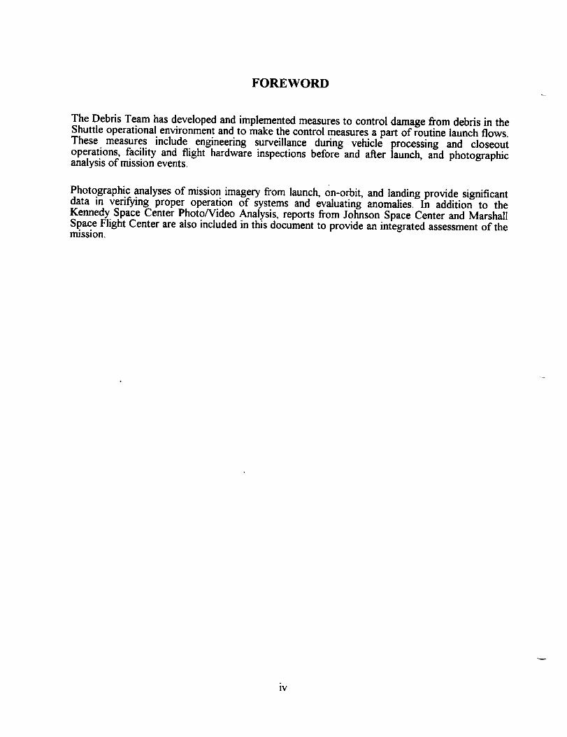
Photo 2:STS-75 Cryoloaded for Launch
OV- 102 Columbia ( 19th flight), ET-76 (LWT 69), and BI-078 SRB's
7

4
I
r
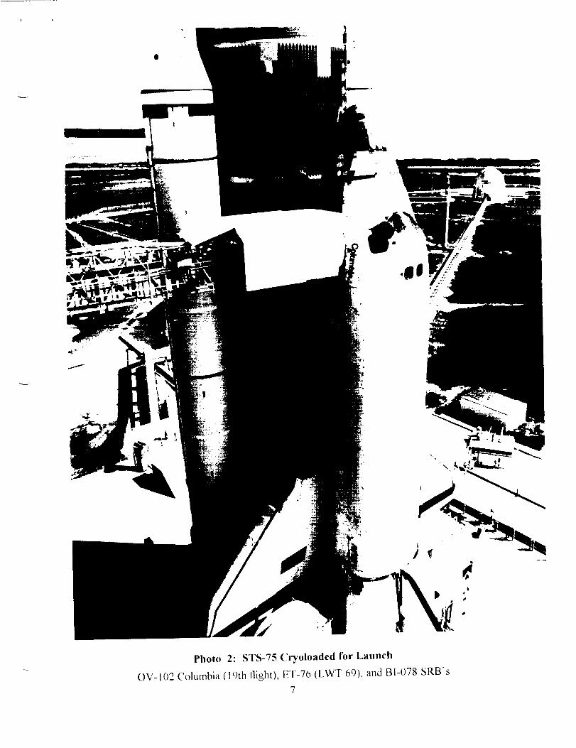
Photo 3:ET-76 Cryoloaded for Launch
8


Photo 4: Overall ViewofSSME's


/
.i
Photo 5: Sodium Hydroxide Residue on GUCP
l0

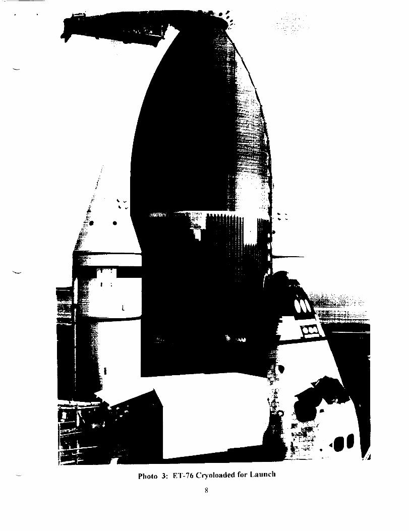
Photo 6: ET/ORB LH2 Umbilical
Less than usual amounts of ice/frost had accumulated on the LH2 ET/ORB umbilical purge
barrier top and outboard sides. Typical ice/frost fingers were present on the pyro canister andplate gap purge vents No unusual vapors or cryogenic drips had appeared during tanking, stable
replenish, and launch.II

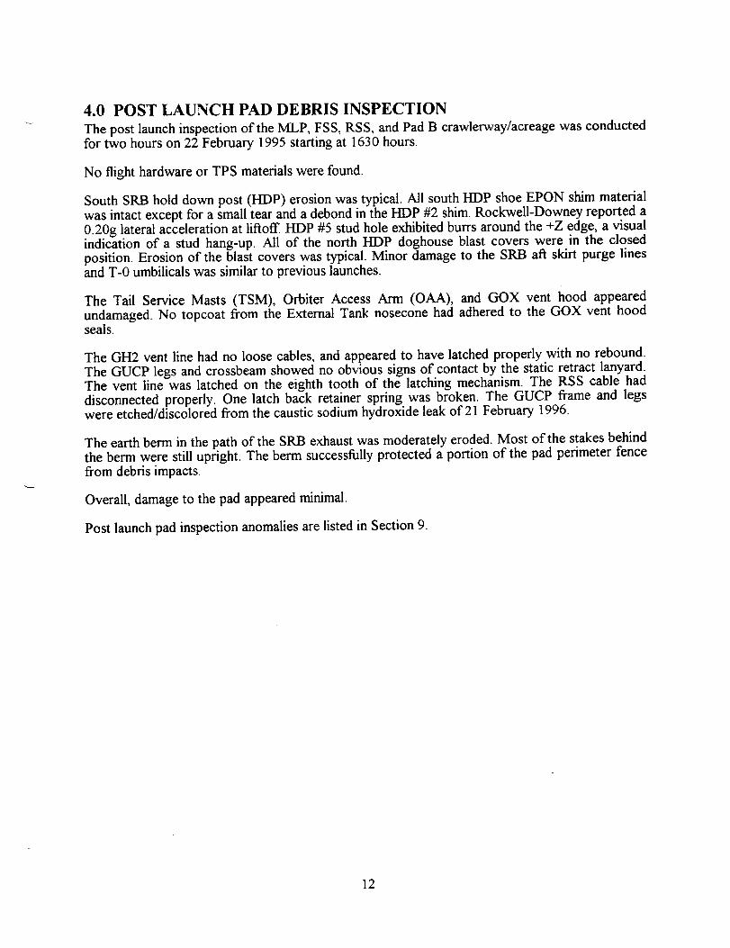
4.0 POST LAUNCH PAD DEBRIS INSPECTION
The post launch inspection of the MLP, FSS, RSS, and Pad B crawlerway/acreage was conductedfor two hours on 22 February 1995 starting at 1630 hours.
No flight hardware or TPS materials were found.
South SRB hold down post (HDP) erosion was typical. All south HDP shoe EPON shim materialwas intact except for a small tear and a debond in the HDP #2 shim. Rockwell-Downey reported a0.20g lateral acceleration at liftoff. HDP #5 stud hole exhibited burrs around the +Z edge, a visualindication of a stud hang-up. All of the north HDP doghouse blast covers were in the closedposition. Erosion of the blast covers was typical. Minor damage to the SRB aft skirt purge linesand T-0 umbilicals was similar to previous launches.
The Tail Service Masts (TSM), Orbiter Access Arm (OAA), and GOX vent hood appearedundamaged. No topcoat from the External Tank nosecone had adhered to the GOX vent hoodseals.
The GH2 vent line had no loose cables, and appeared to have latched properly with no rebound.
The GUCP legs and crossbeam showed no obvious signs of contact by the static retract lanyard.The vent line was latched on the eighth tooth of the latching mechanism. The RSS cable had
disconnected properly. One latch back retainer spring was broken. The GUCP frame and legswere etched/discolored from the caustic sodium hydroxide leak of 21 February 1996.
The earth berm in the path of the SRB exhaust was moderately eroded. Most of the stakes behindthe berm were still upright. The berm successfully protected a portion of the pad perimeter fence
from debris impacts.
Overall, damage to the pad appeared minimal.
Post launch pad inspection anomalies are listed in Section 9.
12

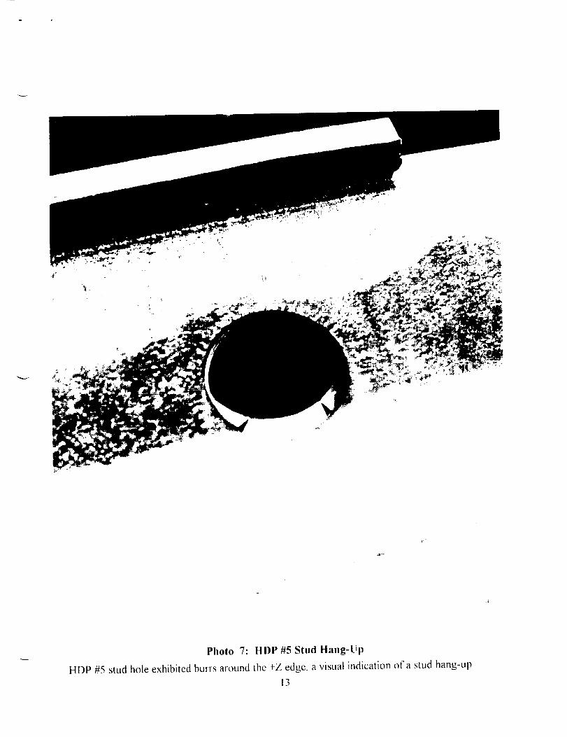
Photo 7: HDP#5StudHang-Up
HDP #5 stud hole exhibited burrs around the +Z edge. a visual indication of a stud hang-up
13

5.0 FILM REVIEW
Anomalies observed in the Film Review were presented to the Mission Management Team,Shuttle managers, and vehicle systems engineers. No IPR's or IFA's were generated as a result ofthe film review. Post flight anomalies are listed in Section 9.
5.1 LAUNCH FILM AND VIDEO SUMMARY
A total of 102 films and videos, which included thirty-nine 16ram films, twenty 35ram films, four70mm films, and thirty-nine videos, were reviewed starting on launch day.
SSME ignition appeared normal. Free burning hydrogen appeared to be less than usual duringSSME startup. A dark spot on the inside wall of the SSME #2 nozzle may be a weld or repair(E-76). A flash, or flare, was visible in the SSME #2 Mach diamond shortly after T-0 (E-31).
SSME ignition caused ice to fall from the ET/ORB umbilicals. Several pieces of ice contacted theLH2 umbilical cavity silt and were deflected outward. No tile damage was visible (OTV 109).
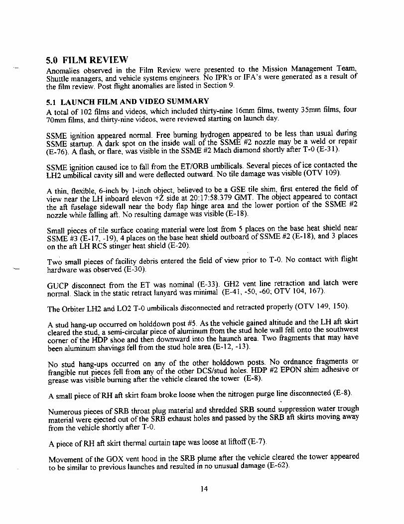
A thin, flexible, 6-inch by 1-inch object, believed to be a GSE tile shim, first entered the field ofview near the LH inboard elevon +Z side at 20:17:58.379 GMT. The object appeared to contactthe aft fuselage sidewall near the body flap hinge area and the lower portion of the SSME #2nozzle while falling aft. No resulting damage was visible (E-18).
Small pieces of tile surface coating material were lost from 5 places on the base heat shield nearSSME #3 (E-17, -19), 4 places on the base heat shield outboard of SSME #2 (E-18), and 3 placeson the aft LH RCS stinger heat shield (E-20).
Two small pieces of facility debris entered the field of view prior to T-0. No contact with flight
hardware was observed (E-30).
GUCP disconnect from the ET was nominal (E-33). GH2 vent line retraction and latch werenormal. Slack in the static retract lanyard was minimal (E-41, -50, -60; OTV 104, 167).
The Orbiter LI-L2 and LO2 T-0 umbilicals disconnected and retracted properly (OTV 149, 150).
A stud hang-up occurred on holddown post #5. As the vehicle gained altitude and the LH aft skirtcleared the stud, a semi-circular piece of aluminum from the stud hole wall fell onto the southwestcorner of the HDP shoe and then downward into the haunch area. Two fragments that may have
been aluminum shavings fell from the stud hole area (E-12, -13).
No stud hang-ups occurred on any of the other holddown posts. No ordnance fragments orfrangible nut pieces fell from any of the other DCS/stud holes. I-IDP #2 EPON shim adhesive orgrease was visible burning after the vehicle cleared the tower (E-8).
A small piece of RH aft skirt foam broke loose when the nitrogen purge line disconnected (E-8).
Numerous pieces of SRB throat plug material and shredded SRB sound suppression water trough
material were ejected out of the SRB exhaust holes and passed by the SRB aft skirts moving awayfrom the vehicle shortly after T-0.
A piece ofRH att skirt thermal curtain tape was loose at liftoff(E-7).
Movement of the GOX vent hood in the SRB plume after the vehicle cleared the tower appeared
to be similar to previous launches and resulted in no unusual damage (E-62).
14

Ice falling att from the ET/ORB umbilicals after the vehicle cleared the tower made 'glancing"contact with lower surface tiles, but no damage was observed (E-52).
A bird passing behind the ET/RaLI SRB from the E-52 eastern tracker vantage point at20:18:08.356 GMT was not near the vehicle (did not appear in western tracker fields-of-view).
Several bright flashes occurred in the SSME plume during ascent. This phenomenon has beenobserved on previous launches and is believed to be caused bydebris passing through the exhaustplume (E-222, -223; TV-4B, TV-21B).
Localized flow condensation formed on various parts of the vehicle at altitude as expected for theambient weather conditions (E-220, -224; TV-SB, TV-21B).
Body flap movement (amplitude and frequency) appeared similar to previous flights (E-213,-220).
ET aft dome charting, exhaust plume recirculation, and SRB separation appeared nominal (E-207,-212).
A considerable portion of the long range tracking coverage was obscured by haze.
15
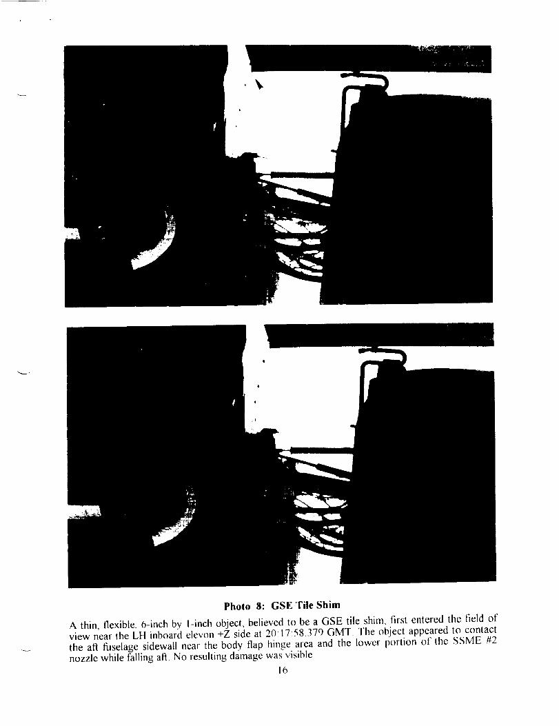
Photo 8: GSE Tile Shim
A thin, flexible, 6-inch by 1-inch object, believed to be a GSE tile shim, first entered the field ofview near the LH inboard elevon +Z side at 20:17:58.379 GMT. The obiect appeared to contact
the aft fuselage sidewall near the body flap hinge area and the lower portion of tile SSME #2nozzle while falling aft. No resulting darnage was visible
16


Photo 9: HDP#5StudHang-Up
A stud hang-up occurred on holddown post _5. As the vehicle gained altitude and the LI4 aft skirtcleared the stud, a semi-circular piece of aluminum from the stud hole wall fell downward into the
haunch area. Two fragments that may have been aluminum shavings fell from the stud hole area.
17

_ J

5.2 ON-ORBIT FILM AND VIDEO SUMMARY
OV-102 was equipped to carry umbilical cameras: 16mm motion picture with 5 mm lens; 16mmmotion picture with 10mm lens; 35mm still views. Data was obtained from all three cameras.Hand held photography taken by the flight crew consisted of seven 35mm images.
No vehicle damage or lost flight hardware was observed that would have been a safety of flightconce/-n.
SRB separation from the External Tank was nominal.
ET-76 separation from the Orbiter also appeared normal. The BSM burn scars on the LO2 tank
were typical. No anomalies were observed on the nosecone, PAL ramps, and LO2 feedline.Likewise, no -Z side acreage TPS anomalies were detected on the LO2 tank, intertank, and LH2barrel.
The umbilical films revealed no ET intertank acreage divots. However, four divots, ranging in sizefrom 6 to 12-inches in diameter, were visible in the intertank-to-LH2 tank flange closeout (one inthe -Y+Z quadrant; three in the +Y+Z quadrant near the EB fitting). In addition, a 5-inchdiameter divot was observed in the LH2 tank acreage near the group of three divots in the flangecloseout.
Both bipod jack pad closeouts were intact.
Erosion of TPS from the LO2 feedline flange closeouts and support brackets, thrust strut flangecloseouts, and LH2 tank pressurization line ramps was typical.
The LH2 ET/ORB umbilical appeared to be in good condition with little or no TPS damage.
Foam was missing or eroded from the horizontal (clamshell) section of the cable tray and the aftsurface of the -Y vertical strut. A thin, metallic object with straight edges (lightning contact strip)originated from the LH2 ET/ORB umbilical area shortly after umbilical separation and drifted in ageneral -Y-Z direction. Two of the five lightning contact strips from the LH2 umbilical appeared
to be missing.
The LO2 ET/ORB umbilical TPS was undamaged. All lightning contact strips were intact.Numerous divots and eroded areas were visible on the horizontal and vertical sections of the cable
tray.
18


Photo I0: Loose Lightning Contact Strip
A thin, metallic object with straight edges (lightning contact strip) originated from the LH2ET/ORB umbilical area shortly after umbilical separation and drifted in a general -Y-Z direction.
19

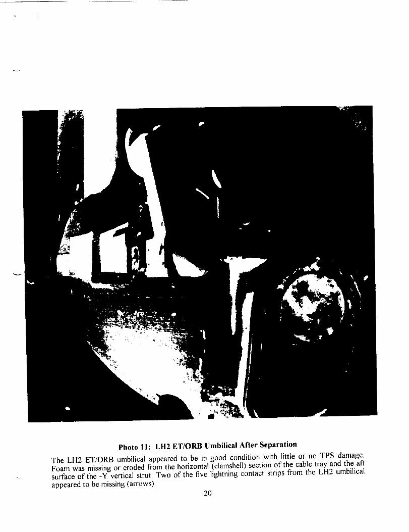
Photo I I: LH2 ET/ORB Umbilical After Separation
The LH2 ET/ORB umbilical appeared to be in good condition with little or no TPS damage.Foam was missing or eroded from the horizontal (clamshell) section of the cable tray and the af_surface of the -Y vertical strut. Two of the five lightning contact strips from the LH2 umbilical
appeared to be missing (arrows).
2O


Photo 12: ET Separation from Orbiter
The LO2 ET/ORB umbilical TPS was undamaged. All lightning contact strips were intact.Numerous divots/eroded areas were visible on the horizontal/vertical sections of the cable tray.
21

q
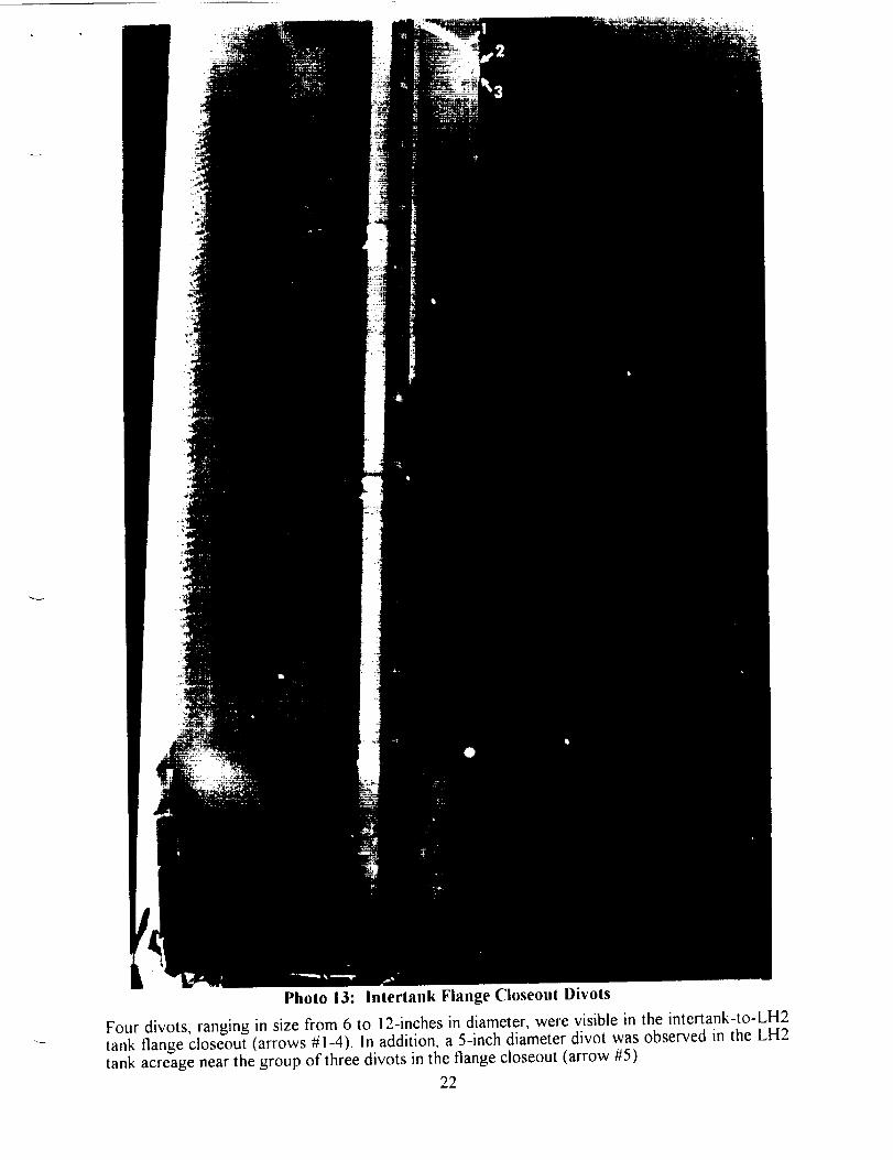
Photo 13: Intertank Flange Cioseout Divots
Four divots, ranging in size from 6 to 12-inches in diameter, were visible in the intertank-to-LH2
tank flange closeout (arrows #1-4). In addition, a 5-inch diameter divot was observed in the LH2tank acreage near the group of three divots in the flange closeout (arrow #5).
22


5.3 LANDING FILM AND VIDEO SUMMARY
A total of 23 films and videos, which included nine 35mm large format films, two 16mm high
speed films, and twelve videos, were reviewed.
The landing gear extended properly. The infrared scanners showed no debris falling from theOrbiter during final approach. Left and right main landing gear touchdown was virtuallysimultaneous at approximately 2200 feet.
Drag chute deployment appeared nominal. However, the drag chute door bounced hard on therunway surface, became airborne, and impacted a runway edge light.
Touchdown of the nose landing gear was smooth.
No significant TPS damage was visible though the forward section of the left payload bay doorexhibited a reddish-brown discoloration. Rollout and wheel stop were uneventful.
23

6.0 SRB POST FLIGHT/RETRIEVAL DEBRIS ASSESSMENT
The BI-078 Solid Rocket Boosters were inspected for debris damage and debris sources at CCASHangar AF on 26 February 1996. From a debris standpoint, both SRB's were in excellentcondition.
6.1 RH SOLID ROCKET BOOSTER DEBRIS INSPECTION
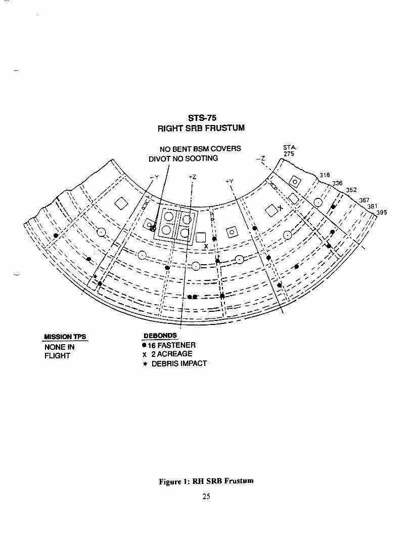
The RI-I frustum was missing no TPS. The number of debonds over fasteners (16) and over
acreage (2) was less than average (Figure 1). Hypalon paint was blistered/missing along the XB-395 ring frame where BTA closeouts had been applied. However, most of the exposed BTAsubstrate was not sooted. The BSM aero heat shield covers had locked in the fully openedposition.
The RH forward skirt exhibited no debonds or missing TPS. Both RSS antennae covers/phenolicbase plates were intact. Hypalon paint was blistered/missing over the areas where BTA closeoutshad been applied. No pins or retainer clips were missing from the frustum severance ring.
The Field Joint Protection System (FJPS) closeouts were generally in good condition. Trailingedge damage to the FJPS and the GEI cork runs were attributed to debris resulting fromseverance of the nozzle extension.
Separation of the aft ET/SRB struts appeared no_. No significant K5NA was missing from theseparation plane of the upper strut fairing. The ETA ring, lEA, and lEA covers appearedundamaged. The aft booster stiffener ring splice plate closeouts were intact and no K5NAmaterial was missing.
Aft skirt MSA-2 was intact. The HDP Debris Containment System (DCS) plungers were seatedand appeared to have functioned properly.
24
STS-75
RIGHT SRB FRUSTUM
NO BENT BSM COVERS
DIVOT NO SOOTING
STA.275
-Z
MISSION TPS
NONE INFLIGHT
DEBONDS
• 16 FASTENER
X 2 ACREAGE
* DEBRIS IMPACT
//
/
381
Figure 1: RH SRB Frustum
25


Photo 14: RH Frustum
The RH frustum was missing no TPS, The number of debonds over fasteners (16) and overacreage (2) was less than average• Hypalon paint was blistered/missing along the XB-395 ringframe where BTA closeouts had been applied• However, most of the exposed BTA substrate wasnot sooted• The BSM aero heat shield covers had locked in the fully opened position•
26

_ J
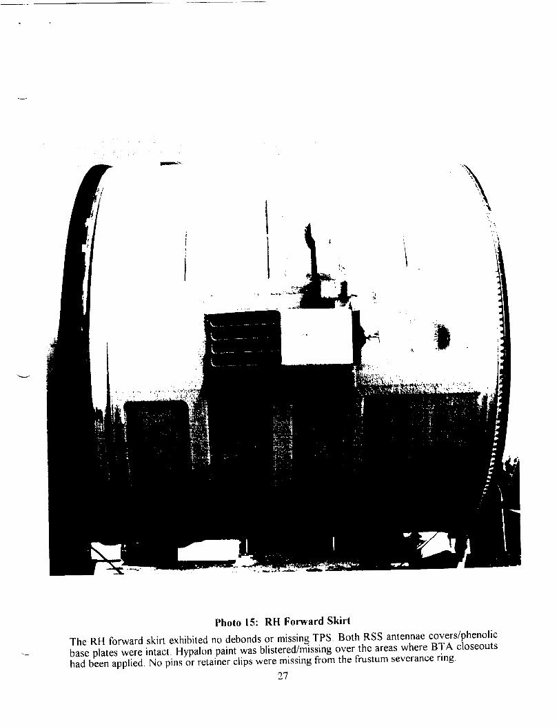
Photo 15: RH Forward Skirl
The RH forward skirt exhibited no debonds or missing TPS. Both RSS antennae covers/phenolic
base plates were intact. Hypalon paint was blistered/missing over the areas where BTA closeoutshad been applied• No pins or retainer clips were missing from the frustum severance ring.
27


Photo 16: RH Aft Booster/Aft Skirt
Separation of the aft ET/SRB struts appeared normal.
28

"_qm , #
6.2 LH SOLID ROCKET BOOSTER DEBRIS INSPECTION
The LH frustum was missing no TPS. The number of MSA-2 debonds over fasteners (20) wasless than average (figure 2). Hypalon paint was blistered/missing along the XB-395 ring framewhere BTA closeouts had been applied. However, most of the exposed BTA substrate was notsooted. The BSM aero heat shield covers had locked in the fully opened position though the tworight cover attach rings had been bent by parachute riser entanglement after splashdown.
The LH forward skirt exhibited no debonds or missing TPS. Both RSS antennae covers/phenolicbase plates were intact. Hypalon paint was blistered/missing over the areas where BTA closeoutshad been applied. None of the pins and retainer clips were missing from the frustum severancering.
The Field Joint Protection System (FJPS) closeouts were in good condition. In general, minortrailing edge damage to the FJPS and the GEl cork runs were attributed to debris resulting fromseverance of the nozzle extension.
Separation of the aft ET/SRB struts appeared normal. No significant K5NA was missing from theseparation plane of the upper strut fairing. The lEA and IEA covers appeared undamaged. Thestiffener rings were damaged by water impact. The stiffener ring splice plate closeouts were intactand no K5NA material was missing.
Numerous aft skirt MSA-2 divots exhibited clean substrates and adjacent material. Lack ofsooting in the divots indicate occurrences late in flight or after splashdown.
A stud hang-up occurred on HDP #5 and the hole was broached. Stud thread impressions werevisible in the stud hole wall. The stud hang-up was confirmed in the launch film review on filmitem E- 12.
The HDP #6 and #7 Debris Containment System (DCS) plungers were obstructed by ordnancefragments and frangible nut halves, respectively. No anomalies on these two holddown posts wereobserved in the launch films and the two conditions were most likely caused"by water impact.
SRB Post Launch Anomalies are listed in Section 9.
29

STY75
LEFT SRB FRUSTUM
-z BENT BSM/ COVERS
STA.275
395
MISSION TPS
NONE
DEBONDS
• 20
Figure 2: LH SRB Frustum
30

• °
/
Photo 17: LH Frustum
The LH frustum was missing no TPS. The number of MSA-2 debonds over fasteners (20) wasless than average• The BSM aero heat shield covers had locked in the fully opened position
though the two right cover attach rings had been bent by parachute riser entanglement after
splashdown,
31


\
Photo 18: LH Forward Skirt
The LH forward skirt exhibited no debonds or missing TPS, Both RSS antennae covers/phenolic
base plates were intact. Hypalon paint was blistered/missing over the areas where BTA closeoutshad been applied. None of the pins/retainer clips were missing from the frustum severance ring.
32


.....
Photo 19: LH Aft Booster/Aft Skirt
33

-,,.._

f
Photo 20: Stud Holes #5 and #6
A stud hang-up occurred on HDP #5 and the hole was broached. Stud thread impressions werevisible in the stud hole wall (top view). The HDP #6 Debris Containment System plunger wasobstructed by ordnance fragments. No anomalies on this holddown post were observed in thelaunch films and the condition was most likely caused by water impact (bottom view).
34

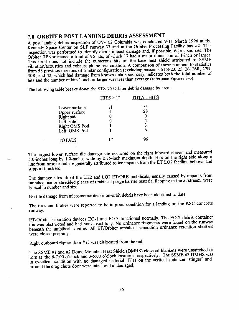
7.0 ORBITER POST LANDING DEBRIS ASSESSMENT
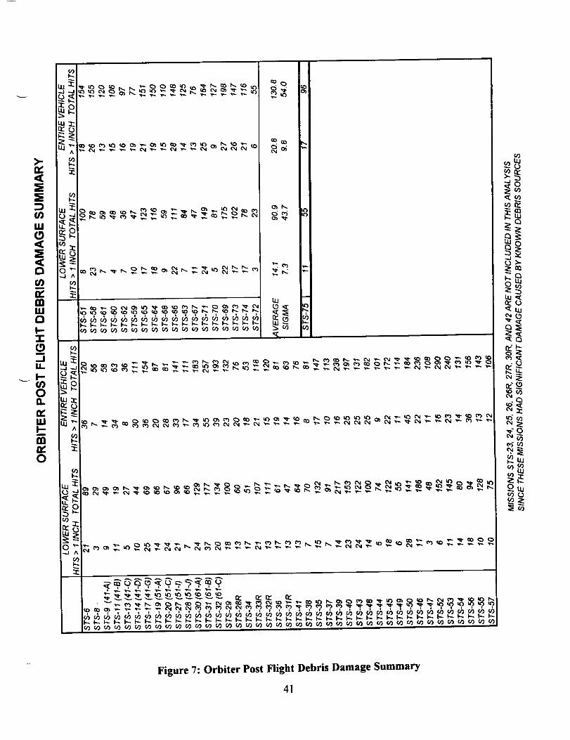
A post landing debris inspection of OV-102 Columbia was conducted 9-11 March 1996 at theKennedy Space Center on SLF runway 33 and in the Orbiter Processing Facility bay #2. Thisinspection was performed to identify debris impact damage and, if possible, debris sources. TheOrbiter TPS sustained a total of 96 hits, of which 17 had a major dimension of 1-inch or larger.This total does not include the numerous hits on the base heat shield attributed to SSME
vibration/acoustics and exhaust plume recirculation. A comparison of these numbers to statisticsfrom 58 previous missions of similar configuration (excluding missions STS-23, 25, 26, 26R, 27R,30R, and 42, which had damage from known debris sources), indicates both the total number ofhits and the number of hits 1-inch or larger was less than average (reference Figures 3-6).
The following table breaks down the STS-75 Orbiter debris damage by area:
HITS > 1" TOTAL HITS
Lower surface 11 55
Upper surface 4 28Right side 0 0Left side 0 4
Right OMS Pod 1 3Left OMS Pod 1 6
TOTALS 17 96
The largest lower surface tile damage site occurred on the right inboard elevon and measured5.0-inches long by 1.0-inches wide by 0.75-inch maximum depth. Hits on the right side along aline from nose to tail are generally attributed to ice impacts from the ET LO2 feedline bellows andsupport brackets.
Tile damage sites aft of the LH2 and LO2 ET/ORB umbilicals, usually caused by impacts fromumbilical ice or shredded pieces of umbilical purge barrier material flapping in the airstream, weretypical in number and size.
No tile damage from micrometeorites or on-orbit debris have been identified to date.
The tires and brakes were reported to be in good condition for a landing on the KSC concrete
runway.
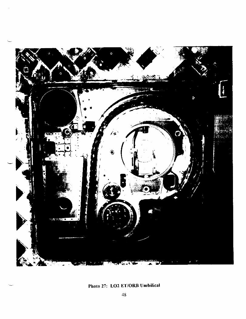
ET/Orbiter separation devices EO-1 and EO-3 functioned normally. The EO-2 debris containeriris was obstructed and had not closed fully. No ordnance fragments were found on the runwaybeneath the umbilical cavities. All ET/Orbiter umbilical separation ordnance retention shutterswere closed properly.
Right outboard flipper door #15 was dislocated from the rail.
The SSME #1 and #2 Dome Mounted Heat Shield (DMHS) closeout blankets were unstitched ortorn at the 6-7:00 o'clock and 3-5:00 o'clock locations, respectively. The SSME #3 DMHS wasin excellent condition with no damaged material. Tiles on the vertical stabilizer %tinger" andaround the drag chute door were intact and undamaged.
35

Tile damage sites on the upper surface of the body flap outboard of SSME #3 (6 places in theRTV coated area and 3 places along the edge) may have been caused by plume impingement fromthe downward firing R5D thruster. Visual inspection showed an approximate size of 5.5-inches by3.5-inches by 0.25-inches deep at two of the tile damage locations.
No ice adhered to the payload bay door. However, a reddish-brown discoloration similar to that
observed previously on OV-105 was present on the leading edge of the LH payload bay door. Adiscoloration around the F 1L thruster was similar in appearance, but may not be related. Sampleswill be taken for microchemical analysis. No unusual tile damage was observed on the leadingedges of the vertical stabilizer. The LH OMS pod leading edge tiles sustained one large hitmeasuring 5-inches long by 1.25-inches wide by 0.5-inches deep along with several smaller hits.This damage may have been caused by impacts from ice on the waste water dump nozzles.
Orbiter window hazing and streaking was typical. The numerous damage sites on the windowperimeter tiles were attributed to a combination of new hits from FRCS thruster papercover/adhesive and old tile repair material flaking off.
The post landing walkdown of Runway 33 was performed immediately atier landing. All dragchute hardware was recovered and appeared to have functioned normally. The drag chute doorhad skidded along the runway and impacted a runway perimeter light. The major pieces of thelight stanchion and lens were recovered.
In summary, both the total number of Orbiter TPS debris hits and the number of hits 1-inch or
larger was less than average when compared to previous missions (Figure 7).
Post Landing Anomalies are listed in Section 9.0.
36

STS-75
DEBRIS DAMAGE LOCATIONS
1.5 x 0.5 x 0.25
ProtrudingGap Filler
5.0 x 1.0 x 0.75
.5 x 1.0 x 0.75
2.0 x 0.5 x 0.25
xO.5xO.25
_I.0 x 0,75 x 0.125
xl.0
1.0 x 1.0 x 0.375
xO.75xO,5
.5 x 0.5 x 0.125
ProtrudingGap Filler
TOTAL HITS : 55
HITS > 1 INCH = 11
ALL DIMENSIONSIN INCHES
2.0 x 0.5 x 0.25
Figure 3: Orbiter Lower Surface Debris Map
37

STS-75
DEBRIS DAMAGE LOCATIONS
2.5 x 0.5 x O.
3 hits:
2x2xO.51 x 0.75 x 0.1I x 0.9 x 0.1
6 hits with 1 hits
1 x 0.5 x 0.1
5 x 1.25 x 0.5
(V070-396-450-033 CTI 499)
TOTAL Hrrs : 34
HITS > 1 INCH = 6
AU_ DIMENSIONSIN INCHES
Figure 4: Orbiter Upper Surface Debris Map
38
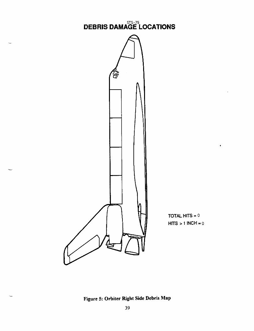
STS-75
DEBRIS DAMAGE LOCATIONS
TOTAL HITS = o
HITS > 1 INCH = o
Figure 5: Orbiter Right Side Debris Map
39
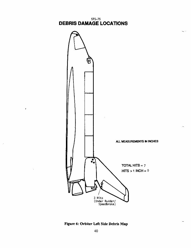
STS-75
DEBRIS DAMAGE LOCATIONS
m
ALLMEASUREMENTSIN INCHES
TOTAL HITS -- 7
HITS > 1 INCH-- 0
(Under Rudder/Speedbrake)
Figure 6: Orbiter Left Side Debris Map
40
_2_ _ ..........
I--
n_ _.0
_Q
0
'_Lu
LU
co
Figure 7: Orbiter Post Flight Debris Damage Summary
41


I I ............... T..L,/_.,_-_..,JJ • . "'. .... L II I I
'ltt/_%\_';,_''' ' ,,_,-:,......._:,_ '
Photo 21: Overall View of Orbiter Left Side
42

J
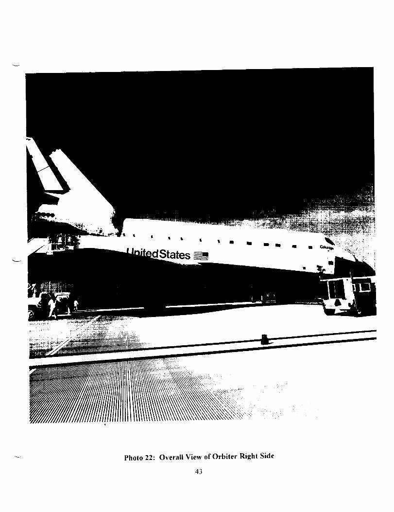
Photo 22: Overall View of Orbiter Right Side
43

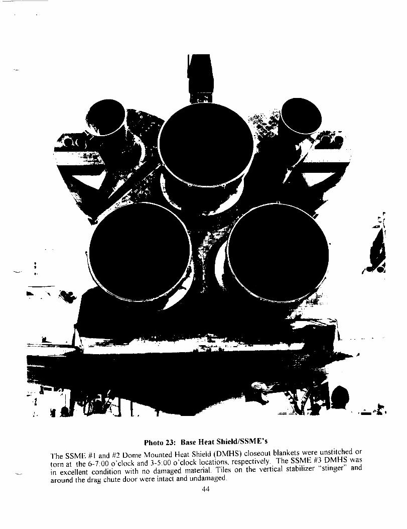
Photo23: BaseHeat Shield/SSME's
The SSME #1 and #2 Dome Mounted Heat Shield (DMHS) closeout blankets were unstitched ortorn at the 6-7:00 o'clock and 3-5:00 o'clock locations, respectively. The SSME #3 DMHS wasin excellent condition with no damaged material, Tiles on the vertical stabilizer "stinger" and
around the drag chute door were intact and undamaged.
44


Photo 24: Lower Surface Tile Damage
The largest lower surface tile damage site occurred on the right inboard elevon and measured5.0-inches long by I 0-inches wide by 0.75-inch maximum depth Hits on the right side along aline from nose to tail are generally attributed to ice impacts from the ET LO2 feedline bellows and
support brackets45


©
!
Photo 25:LH2 ET/ORB Umbilical
46


Photo 26:EO-2 Debris Container |ris
ET/Orbiter separation devices EO-I and EO-3 functioned normally. The EO-2 debris containeriris was obstructed and had not closed fully No ordnance fragments were found on the runway
beneath the umbilical cavities
47

÷"t.
/
Photo 27:LO2 ET/ORB Umbilical
48


r !_ -•
Photo 28: Flipper Door #15
Right outboard flipper door # 15 was dislocated from the rail49


\o
Photo 29: Payload Bay Door Discoloration
No ice adhered to the payload bay door. However, a reddish-brown discoloration similar to thatobserved previously on OV-105 was present on the leading edge of the LH payload bay door.
50


\
Photo 30: Orbiter Windows
Orbiter window hazing and streaking was typical The numerous damage sites on the vsindmv
perimeter tiles were attributed to a combination of new hits from FRCS thruster papercover/adhesive and old tile repair material flaking off"
51

J

Photo 31: Runway Ligh! Damage
All drag chute hardware was recovered and appeared to have functioned normally The dragchute door had skidded along the runway and impacted a runway perimeter light, l'he ma or-
pieces of the light stanchion and lens were recovered52


8,0 DEBRIS SAMPLE LAB REPORTS
A total of eight samples were obtained from OV-102 Columbia during the STS-75 post landingdebris assessment at Kennedy Space Center. The submitted samples consisted of 8 wipes fromOrbiter windows #1-8. The samples were analyzed by the NASA KSC Microchemical AnalysisBranch (MAB) for material composition and comparison to known STS materials. Debris analysisinvolves both the placing and the correlating of particles and residues with respect to composition,thermal (mission) effects, and availability. Debris sample results/analyses are listed by Orbiterlocation in the following summaries.
8.1 ORBITER WINDOWS
Samples from the Orbiter windows indicated exposure to facility environment, SRB BSM exhaust(including metallic particulate), landing site materials (earth minerals), Orbiter Thermal ProtectionSystem (tile repair, and glass insulation), Orbiter window polish residue, building type insulation,paints and primer from various sources. There was no apparent vehicle damage related to theseresiduals.
8.2 ORGANIC ANALYSIS
The results of the STS-75 organic analysis are pending.
8.3 STS-72 PRELAUNCH ORGANIC ANALYSIS
The results of the recently-received STS-72 prelaunch organic sample analysis revealed thepresence of RTV (RCS nozzle cover and ORB TPS), phenolic, isocyanurate foam and epoxymaterials. These particulate types are common to STS processing. The precise sources are underassessment.
8.4 NEW FINDINGS
This set of post-flight debris residual samples provided added data to source information for STSdebris sampling. The STS-72 prelaunch window and window cover samples organic analysis hasshown the presence of polyamide in sample wipe. This material had previously been attributed to
the window covers. The presence of phenolic and isocyanurate foam is also being evaluated as anew finding, although these material types are common to the STS environment. The variety ofresidual material continues to be representative of that documented in previous mission sampling(reference Figure 8 for STS-75).
53

Am
(nv
-o
(/)Am O
on" E_m c E
3;Jw= ,--I.
_o __-_. e _ __ i_
_ _ _. _._,,, _ ;._
"''" -_® i_!= eo ,m m: . ""(Y
_O
_o_- _ ._ _-
_-_- _8_ _$ _ "_ ,-
=_--_mwO
A
A i_mm
3e
i )),ii,,-_; o::__ ,r, u,,a0 _ cn
A A
(nO,.
:;rn _.i= _ -.'_-
Figure 8: Orbiter Post Landing Microchemical Sample Results
54
o)
tOt--(/)
o3
&
iEo
m,

O_
Iv"
o_O
o
QO. ,.__,,.... ® --
_0,,_ _o
_" _ .o_
E _®_- _,=_ _-
.u n,"
I,,,.
Figure 8 (continued):
m_
E>,
_/)n r" I_ "0rn _'...', c:
_®_E
._o_ =, , E ._
_Ei.: =i.T_.mO_.
I1
o_
.0_ _-_o
.=__.0_ "z"
L
= .__ -__ _-.-..i_ _,
Q_IZ
.0 I1__,o
u O.
_-r
A
_" I-- _n _ -u,,=-'In e _ m
. . @ U-" O.)
_.'= 0 "--_f.) c
_--_ciE m 0 -, _
_D_D
>¢ e--
nI-.
n..n,
._-_
.uo
o
_. ".-'c _-_
-" _= iy. m 0 n- o.
0__D
Orbiter Post Landing Microchemical Sample Results
O_
t-
o
o
E2
._o
o
>
o
oU_

E
iO
A |I3E _-
__JI!o;_E|
u. i11 0 11_ _
np-
n_lg
A _ A
geE_N_
mc _
A
!!,E---
Figure 8 (continued): Orbiter Post Landing Microchemicai Sample Results
56
GO
oo
g3.
_0
!t_
Eo
!el
E
i
9.0 POST LAUNCH ANOMALIES
Based on the debris walkdowns and film/video review, 7 post launch anomalies, but no In-Flight
Anomalies (IFA's), were observed on the STS-75 mission.
9.1 LAUNCH PAD/SHUTTLE LANDING FACILITY
1. No items.
9.2 SOLID ROCKET BOOSTERS
I. A stud hang-up occurred on holddown post #5. As the vehicle gained altitude and the LH aftskirt cleared the stud, a semi-circular piece of aluminum from the stud hole wall fell onto thesouthwest corner of the HDP shoe and then downward into the haunch area. Two fragments thatmay have been aluminum shavings fell from the stud hole area.
9.3 EXTERNAL TANK
1. Four divots, ranging in size from 6 to 12-inches in diameter, were visible in the intertank-to-LH2 tank flange cioseout (one in the -Y+Z quadrant; three in the +Y+Z quadrant near the EBfitting). In addition, a $-inch diameter divot was observed in the LH2 tank acreage near the groupof three divots in the flange closeout.
2. A thin, metallic object with straight edges (lightning contact strip) originated from the LH2ET/ORB umbilical area shortly after umbilical separation and drifted in a general -Y-Z direction.Three other lightning contact strips from the LH2 umbilical appeared to be missing - a conditionthat could not be confirmed due to the sun angle/lighting conditions. Loss of lightning contact
strips has been documented on previous IFA's.
9.4 ORBITER
1. A thin, flexible, 6-inch by l-inch object, believed to be a GSE tile shim, first entered the field ofview near the LH inboard devon +Z side at 20:17:58.379 GMT. The object appeared to contact
the aft fuselage sidewall near the body flap hinge area and the lower portion of the SSME #2nozzle while falling aft. No resulting damage was visible. The GSE shim should have been
removed before flight.
2. The EO-2 debris container iris was obstructed and had not closed fully.
3. Right outboard flipper door #15 was dislocated from the rail.
4. A reddish-brown discoloration was present on the leading edge of the LH payload bay door.
57

APPENDIX A. JSC PHOTOGRAPHIC ANALYSIS SUMMARY


Space ShuttleEarth Science Branch
Image Science andAnalysis Group
STS-75 Summary ofSignificant Events
April 15, 1996
A1

Space ShuttleImage Science andAnalysis Group
STS-75 Summary of Significant Events
Project Work Order - SN-5CR
Approved By
Lockheed Martin
Robert Meltzer, Project AnalystImage Science and Analysis Group
M. H. Trenchard, Project ManagerImage Analysis Projects
NASA
_JDiane McLaughlin_,)sad
Image Science and Analysis GroupEarth Science Branch
J_G. Cames, Operations ManagerB_c and Applied Research Department
Prepared By
Lockheed Martin Engineering and Sciences Companyfor
Earth Science Branch
Earth Sciences and Solar System Exploration Division
Space and Life Sciences Directorate
A2


Table of Contents
1. STS-75 (OV-102): FILM / VIDEO SCREENING AND TIMING SUMMARY ........... A5
1.1 SCREENING ACTIVITIES .................................................. AS1.1.1 Launch .................................................................................................................................................... A5
1.1.2 Landing .................................................................................................................................................... A5
1.2 TIMING ACTIVITIES ...................................................... A5
2. SUMMARY OF SIGNIFICANT EVENTS ................................................................. A7
2.1 DEBRIS ........................................................................................................................ A7
2.1.1 Debris Near the Time of SSME Ignition ................................................................. A72.1.1.1 Debris Aft of Body Flap .................................................................................... A72.1.1.2 Debris Strikes LH2 Umbilical Door Sill ............................................................ A72.1.1.3 Debris Near LSRB ............................................................................................. A8
2.1.1.4 Rectangular Shaped Debris Strikes Orbiter. ...................................................... A92.1.2 Debris Near the Time of SRB Ignition .................................................................... A9
2.1.2.1 Bolt Hang-Up on the LSRB Holddown Post M-5 ........................................... A102.1.2.2 Metallic Debris Seen Near M-5 Holddown Post ............................................. A11
2.1.2.3 Thermal Curtain Tape Seen Near RSRB ......................................................... All2.1.2.4 Flame Trench Debris ....................................................................................... A122.1.2.5 Debris from ET/RSRB Aft Attach Bottom Strut. ............................................ A122.1.2.6 Debris Strikes Tile Surface .............................................................................. A12
2.1.2.7 LH2 and LO2 Tail Service Mast (TSM) T-0 Umbilical Disconnect Debris... A132.1.2.8 GH2 Vent Arm Debris During Disconnect and Retraction ............................. A14
2.1.3 Debris After Liftoff ............................................................................................... A142.1.3.1 Debris in Exhaust Cloud .................................................................................. A142.1.3.2 Debris In SSME Exhaust Plume ..................................................................... A14
2.2 MOBILE LAUNCH PLATFORM (MLP) EVENTS ........................................... A152.2.1 Tile Surface Erosion .............................................................................................. A15
2.2.2 Orange Vapor ........................................................................................................ A152.2.3 SSME Mach Diamond Formation ......................................................................... A15
2.3 ASCENT EVENTS .............................................................................................. AI62.3.1 Flares in SSME Exhaust Plume ............................................................................. A16
2.40NBOARD PHOTOGRAPHY OF THE EXTERNAL TANK (DTO-312) .......... A17
2.4.1 Analysis of Handheld Photography of the ET (Task #3) ...................................... A172.4.2 Analysis of the Umbilical Well Camera Films (Task #2) ..................................... A18
2.5 LANDING EVENTS ................................................................................................ A20
2.5.1 Landing Sink Rate Analysis (Task #3) ................................................................. A20
2.6 OTHER .............................................................................................................. A222.6.1 Normal Events ....................................................................................................... A22
II
STS-75 JSC Summary Report A3
Table of Contents
Table 1.2
Figure 2.1.1.1Figure 2.1.1.2
Figure 2.1.1.3Figure 2.1.2.1 (A)Figure 2.1.2.2 03)Table 2.1.2.2
Figure 2.1.2.5Figure 2.2.2Figure 2.3.1Figure 2.4.1 (A)Figure 2.4.1 03)Figure 2.4.2Figure 2.4.3Table 2.5.1
Figure 2.5.1Figure 2.5.2
Landing Video Timing Events ...................................................................... 6Debris Aft of Body Flap ................................................................................ 7Debris Near LSRB ........................................................................................ 8Debris Strikes Orbiter ................................................................................... 9Holddown Post Bolt Hang-Up .................................................................... 10Metallic Debris Near Holddown Post M-5 ................................................. 11
SRB Holddown Post Bolt Hang-Ups Seen on Previous Missions .............. 11Debris From ET/RSRB Aft Attach ............................................................. 12Orange Vapor .............................................................................................. 15Flares in SSME Exhaust Plume .................................................................. 16Separation Velocity ..................................................................................... 17
35 mm Handheld (Nikon F4) External Tank Photography (DTO-312) ..... 18Possible Lightning Contact Strip (5 MM Camera View) ........................... 19Debris Strikes LSRB(35 MM Camera View) ............................................. 20Sink Rate Measurements ............................................................................. 21
Main Gear Height Versus Time Prior to Touchdown (Film) ...................... 21
Nose Gear Height Versus Time Prior to Touchdown (Film) ...................... 22
STS-75 JSC Sununary Report A4

1. STS-75 (OV-102): Film/Video Screening and Timing Summary
lo
1.1.2
1.2
STS-75 (OV-102): FILM / VIDEO SCREENING AND TIMINGSUMMARY
SCREENING ACTIVITIES
Launch
The STS-75 launch of Columbia (OV-102) from pad B occurred on Thursday,February 22, 1996, (day 053) at 20:18:00.013 Coordinated Universal Time CtYl'C)as seen on camera E9. Solid Rocket Booster (SRB) separation occurred at20:20:06.309 UTC as seen on camera ET212.
On launch day 24 of 24 expected videos were received and screened. Followinglaunch day, 53 films were screened. No potential anomalies were observedduring launch.
Detailed Test Objective 312, photography of the external tank after separation,was performed using the Orbiter umbilical well cameras (method 1) and handheld
photography of the external tank using the Nikon F4 with the 400 mm lens plus2X converter.
Landing
Columbia landed on runway 33 at KSC on March 9, 1996. Twelve videos andeleven films of the Orbiter's approach and landing were received.
No major anomalies were noted in any of the approach, landing, or roll-out
video views screened. The drag chute deployment appeared normal.
TIMING ACTIVITIES
Launch."
The time codes from videos and films were used to identify specific events duringthe initial screening process.
Video cameras: ET204, ET 207, ET208, ET212, ET213, KTV2, KTV5, KTV13,KTV4B, KTV7B, KTV21B, KTV11B, OTV150, had IRIG timing.
Film carneras: E31, EA1, E204, E205, E207, E208, E212, E213, E218, E220, and
E223 had IRIG timing. El, E2, E3, EA, E5, E6, E7, E8, E9, El0, E11, El2, El3,El4, El5, El6, El7, El8, El9, E20, E25, E26, E30, E33, E34, E35, E36, E40,E50, E52, E54, E57, E59, E60, E62, E63, E65, E76, E77, E79, and E222 had in-
frame alphanumeric timing.
m
STS-75 JSC Summary Report A5

lo STS-75 (OV-102): Film/Video Screening and Timing Summary
Video cameras: Twelve videos were screened on landing day. Eight videos:KTV5L, KTV6L, KTV11L, KTV12L, KTV13L, KTV15L, KTV20L, KTV33L,
and EL17 IR had IRIG timing. There was no IRIG timing for videos EL18, SLFSouth, SLF North.
Film cameras: Film cameras ELI, EL2, ELA, EL7, EL8, EL9, EL10, EL12, EL15,
EL30, and EL31 had in-frame alphanumeric timing.
The landing and drag chute event times are provided in Table 1.2.
Event Description Time (UTC) Camera
Landing Gear- Doors Opened
Right Main Wheel Touchdown
Left Main Wheel Touchdown
Drag Chute Initiation
Pilot Chute at Full Inflation
Bag Release
Drag Chute Inflation in ReefedConfiguration
Drag Chute Inflation inDisreefed Configuration
Nose Wheel Touchdown
Drag Chute Release
Wheel stop
069:13:58:01.314
069:13:58:20.213
069:13:58:20.313
069:13:58:28.112
069:13:58:29.013
069:13:58:29.689
069:13:58:30.547
069:13:58:33.774
069:13:58:35.462
069:13:58:51.802
069:13:59:23.156
KTV12L
EL17 IR
EL17 IR
KTV6L
KTV6L
KTV6L
KTV6L
KTV33L
EL17 IR
KTV6L
KTV33L
Table 1.2 Landing Video Timing Events
m
STS-75 JSC Summary Report A6

2. Summary of Significant EventsI
.
2.1
2.1.1
2.1.1.1
SUMMARY OF SIGNIFICANT EVENTS
DEBRIS
Debris Near the Time of SSME Ignition
As on previous missions, multiple pieces of debris were seen near the time ofSSME ignition. Most of the debris was umbilical ice and RCS paper. No follow-up action was requested.
Debris Aft of Body Flap(Camera: OTV 163)
Figure 2.1.1.1 Debris Aft of Body Flap
A single piece of light colored debris (possible flame duct debris) was seen aft ofthe body flap prior to liftoff (53:20:17:55.055 UTC). The debris was not seen tocontact the vehicle.
2.1.1.2 Debris Strikes LH2 Umbilical Door Sill
(Camera: OTV 109)
A single light colored piece of debris (probable ice debris) hit the LH2 umbilicaldoor sill at SSME ignition (053:20:17:57.056 UTC). No damage to the vehiclewas noted.
Elm
STS-75 JSC Summary Report A7


2. Summary of Significant EventsI
2.1.1.3 Debris Near LSRB
(Cameras: E3())
Figure 2.1.1.2 Debris Near LSRB
A small dark piece of debris fell between the camera and the LSRB priorto liftoff (20:17:57.651 UTC). The debris was not .seen to contact thevehicle.
I
STS-75 JSC Summary Report A8


2. Summary of Significant Events
2.1.1.4 Rectangular Shaped Debris Strikes Orbiter(Cameras: E 18)
Figure 2.1.1.3 Debris Strikes Orbiter
A thin, rectangular shaped, light colored piece of debris (possible tile gap filler) fellfrom the top of the view and struck the Orbiter forward of the LH2 TSM T-0 umbilical,and then struck the exterior of the SSME #2 engine bell just prior to liftoff (17:58.962UTC). No damage to the launch vehicle was visible.
2.1.2 Debris Near the Time of SRB Ignition
As on previous missions, multiple pieces of debris were seen near the time ofSRB ignition. No follow-up action was requested.
I
STS-75 JSC Summary Report A9

2. Summary of Significant Events
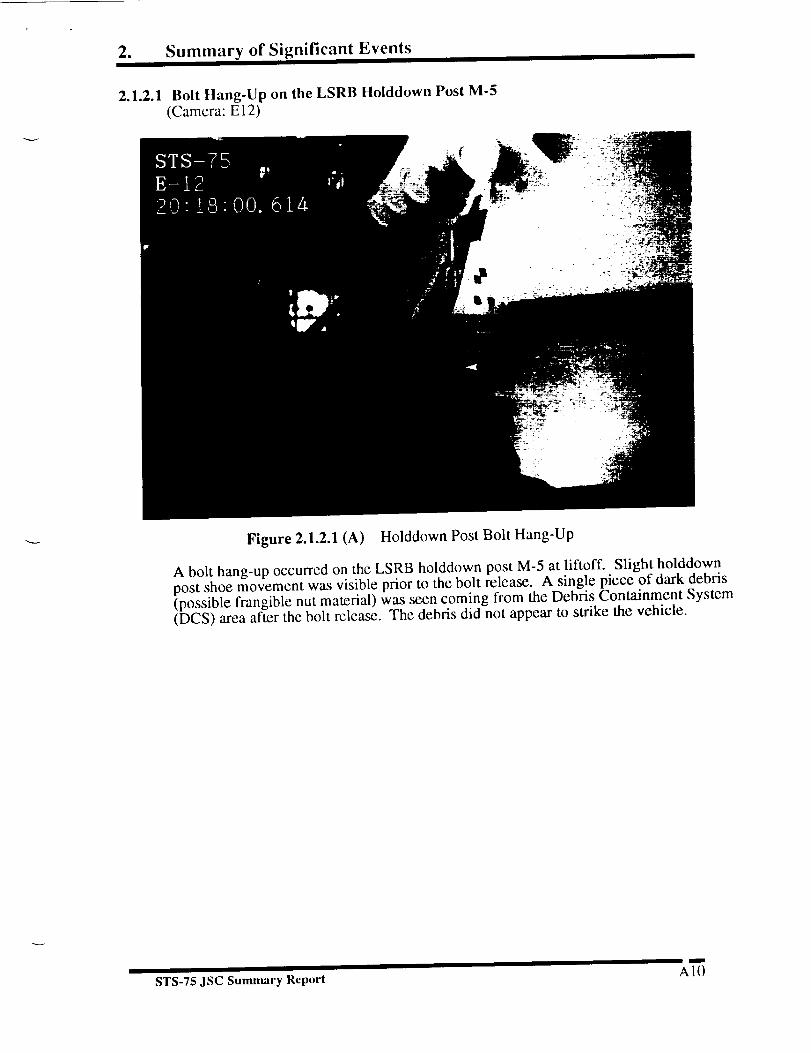
2.1.2.1 Bolt Hang-Up on the LSRB Holddown Post M-5(Camera: E 12)
Figure 2.1.2.1 (A) Holddown Post Bolt Hang-Up
A bolt hang-up occurred on the LSRB holddown post M-5 at lifloff. Slight holddownpost shoe movement was visible prior to the bolt release. A single piece of dark debris(possible frangible nut material) was seen coming from the Debris Containment System(DCS) area after the bolt release. The debris did not appear to strike the vehicle.
I
STS-75 JSC Sumnmry Report A l 0


2. Summary of Significant Events
2.1.2.2 Metallic Debris Seen Near M-5 Holddown Post
(Camera: El2)
Figure 2.1.2.2 (B) Metallic Debris Near Holddown Post M-5
During M-5 bolt release a long, thin, piece of metallic debris was seen comingfrom the SRB bolt cavity. The debris struck the holddown post shoe and then felldown into the haunch area. No follow-up action was requested.
MISSION
STS-34
LOCATION OF HANG-UP
RSRBSTS-33 RSRB
RSRBSTS-39
STS-43
STS-45
STS-50
STS-46
STS-53
STS-73
LSRB
holddown post M-2
holddown post M-3
holddown post M-1
holddown post M-7
RSRB holddown post M-4
RSRB holddown post M-4
LSRB holddown post M-7RSRB holddown post M-1
RSRB holddown post M-2
Table 2.1.2.2 SRB Holddown Post Bolt Hang-Ups Seen on Previous Missions
m
STS-75 JSC Summary Report A 1 I


2. Summary of Significant EventsI I
2.1.2.3
2.1.2.4
2.1.2.5
Thermal Curtain Tape Seen Near RSRB(Camera: E7)
A loose thermal curtain tape was seen on the RSRB aft skirt near holddown post M-4 atliftoff. Loose thermal curtain tape has been seen on previous missions. No follow-upaction was requested.
Flame Trench Debris
(Camera: E57)
Several pieces of light colored debris were seen coming from the SRBflame trench area at liftoff (20:18:02.293 UTC). The debris tracked in anortherly direction and did not contact the vehicle.
Debris from ET/RSRB Aft Attach Bottom Strut
(Cameras: E50, E60, E57)
Figure 2.1.2.5 Debris from ET/RSRB Aft Attach
A single white colored piece of debris fell from the ET end of theET/RSRB aft attach bottom strut during liftoff (20:18:03.266 UTC). Thedebris did not strike the vehicle.
2.1.2.6 Debris Strikes Tile Surface
(Camera: E52)
Several pieces of ice debris from the ET/Orbiter umbilicals struck the Orbiterlower tile surface forward of the body flap during liftoff (20:18:04.334 UTC).Also a single piece of ice debris from the ET/Orbiter umbilicals struck the lowerbody flap tiles at tower clear (20:18:05.377 UTC). No damage to the tiles wasobserved.
I 1 m
STS-75 JSC Summary Report A 12


2. Summary of Significant Events
2.1.2.7
2.1.2.8
2.1.3
2.1.3.1
2.1.3.2
LH2 and LO2 Tall Service Mast (TSM) T-0 Umbilical Disconnect Debris(Cameras: OTV109, OTV149, OTV150, OTV151, OTV163, OTV170, OTV171,El7, El8, El9, E20, E76, E77)
Normal ice debris was noted falling from the LH2 and LO2 TSM T-0 umbilicaldisconnect areas at liftoff. None of the debris was observed to strike the vehicle.
GH2 Vent Arm Debris During Disconnect and Retraction(Cameras: E33, E34, E35, E41, E50, E54)
Vapor and multiple light colored pieces of ice debris fell from the GH2 vent armcarrier plate at vent arm retraction. The GH2 vent arm appeared to retractnormally.
Debris After Liftoff
(Camera: EA0, E52, E57, E59, E213, E220, E222, E223)
Multiple pieces of debris were seen falling aft of the Shuttle Launch Vehicle(SLV) after liftoff on the launch tracking views. The debris was probablyreaction control system (RCS) paper and ice from the ET/Orbiter umbilicals.None of the debris was seen to contact the launch vehicle. No follow-up actionwas requested.
Debris in Exhaust Cloud
(Cameras: EA, E77)
Rope like debris (possible water baffle material) was seen in the exhaustcloud after liftoff (20:18:03.852 UTC).
Debris In SSME Exhaust Plume
(Camera: E52, E57, E220, E222, E223)
E213, E222 - Multiple light colored pieces of debris (probably umbilicalice and RCS paper) were seen falling aft of the vehicle after the rollmaneuver (20:18:17.4 - 20:18:39 UTC). Examples include (1) a single
orange colored piece of debris between the SRB nozzles (20:18:14 UTC)(this debris may have been a piece of umbilical purge barrier material, (2)
a single light colored piece of debris falling over the right Orbiter wing(20:18:24.6 UTC), (3) a single light colored piece of debris near the bodyflap (20:18:39.3 UTC).
I I m
STS-75 JSC Summary Report A13


2. Summary of Significant Events
2.2 MOBILE LAUNCH PLATFORM (MLP) EVENTS
2.2.1 Tile Surface Erosion
(Cameras: E 17, E 18, E20)
Small areas of tile surface coating erosion were noted on the base of the left RCSstinger, on the base of the right OMS pod, and on the base heat shield near SSME# 2 and #3 during SSME ignition, tile surface erosion has been seen on previousmissions. No follow-up action was requested.
2.2.2 Orange Vapor(Cameras: OTV 170, OTV 171)
Figure 2.2.2 Orange Vapor
Orange vapor (possible free burning hydrogen) was seen above the rim of SSME #1prior to liftoff. Orange vapor has been seen on previous missions. No follow-up actionwas requested.
2.2.3 SSME Mach Diamond Formation
(Cameras: OTV151, OTV170, OTV171)
The SSME Mach Diamonds formed in the normal sequence. The times of the
Mach Diamond sequence were:
SSME #3 - 053:20:17:56.690 UTCSSME #2 - 053:20:17:56.890 UTCSSME #1 - 053:20:17:57.023 UTC
I I
STS-75 JSC Summary Report A 14


2. Summary of Significant Events
ASCENT EVENTS
Flares in SSME Exhaust Plume
(Cameras: KTV4B, KTV21B, ET207, ET212, E2, E31, E207, E222)
Figure 2.3.1 Flares in SSME Exhaust Plume
Several flares were seen in the SSME exhaust plume from liftoff untilafter the roll maneuver (20:18:00.654 - 20:18:38.677 UTC). Flares in theSSME exhaust plume have been seen on previous missions. No follow-upaction was requested.
STS-75 JSC Summary Report A 15


2. Summary of Significant EventsI I I II
2.4 ONBOARD PHOTOGRAPHY OF THE EXTERNAL TANK (DTO-312)
2.4.1 Analysis of Handheld Photography of the ET (Task #3)
One roll of STS-72 handheld photography was taken using the Nikon F4 with the400 mm lens plus 2X extender. This is the f'u'st time the 400 mm lens has beenused for DTO-312. Also, to compensate for no DTO-312 pitch maneuver an earlyOMS-2 pitch was performed to bring the external tank into view earlier than
would have otherwise been the case. Five usable frames were acquired foranalysis.
1.55
STS-75DTO-312 ET Separation
(3.17mls)
1.50
1.45
A
_1.40
; 1.355
1.30 '
1.25
1.20
15:42
J
I I i
15:50 15:59 16:08 16:16 16:25 16:34 16:42 16:51 17:00 17:08
Time (llE'r)
Figure 2.4.1 (A) ET Separation Velocity
Using the 35 mm handheld (Nikon F4) camera film, the external tank distancewas calculated over a 5 frame sequence. The external tank was calculated to be adistance of 1.21kin away from the Orbiter at 15:45 MET; 86 seconds later at17:11 MET the tank was calculated to be at a distance of 1.54kin. The tank
separation velocity was determined to be 3.17 m/s. Roll rate was estimated at0. l*/see, and tumble rate was estimated at 0.03*/see. The separation velocity androll/tumble rates were similar to previous mission measurements.
17:17
n
ST8-75 JSC Summary Report A16

2. Summary of Significant Events
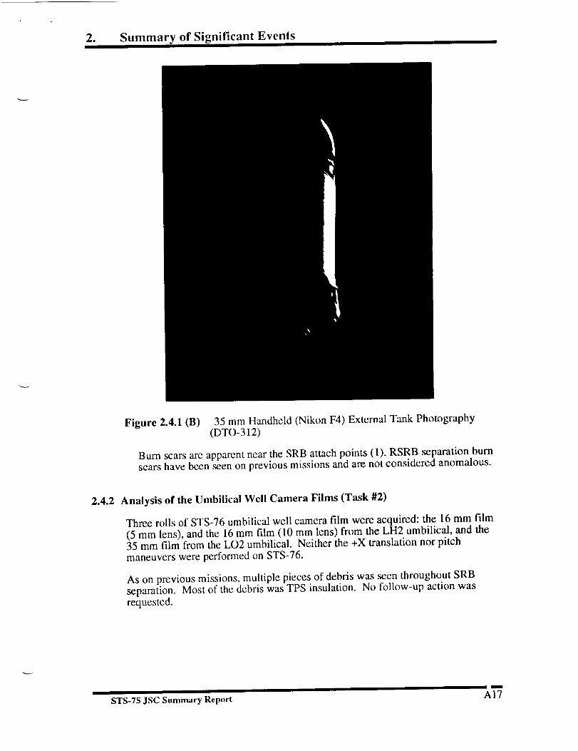
Figure 2.4.1(B) 35 mm Handheld (Nikon F4) External Tank Photography(DTO-312)
Burn scars are apparent near the SRB attach points (1). RSRB separation burnscars have been seen on previous missions and are not considered anomalous.
2.4.2 Analysis of the Umbilical Well Camera Films (Task #2)
Three rolls of STS-76 umbilical well camera film were acquired: the 16 mm film(5 mm lens), and the 16 mm film (10 mm lens) from the LH2 umbilical, and the35 mm film from the LO2 umbilical. Neither the +X translation nor pitchmaneuvers were performed on STS-76.
As on previous missions, multiple pieces of debris was seen throughout SRBseparation. Most of the debris was TPS insulation. No follow-up action wasrequested.
STS-75 JSC Summary Report A_'


2. Summary of Significant EventsI
Figure 2.4.2 Possible Lightning Contact Strip (5 mm Camera View)
A metallic looking piece of rectangular shaped debris (possible lightning contactstrip) first appeared after ET/Orbiter purge between the ET and ET/Orbiterelectrical tray near the LH2 umbilical, the debris moved in a -Y direction away
from the vehicle. The debris did not appear to strike the vehicle. No follow-upaction was requested.
I I I
STS-75 JSC Summary Report A18


2. Summary of Significant Events
Figure 2.4.3 Debris Strikes LSRB (35 mm Camera View)
Several small divots were seen to the right of the forward attach bipod on the +Yside of the ET intertank/LH2 tank flange. Divots on the ET has been seen onprevious missions. No follow-up action was requested.
LANDING EVENTS
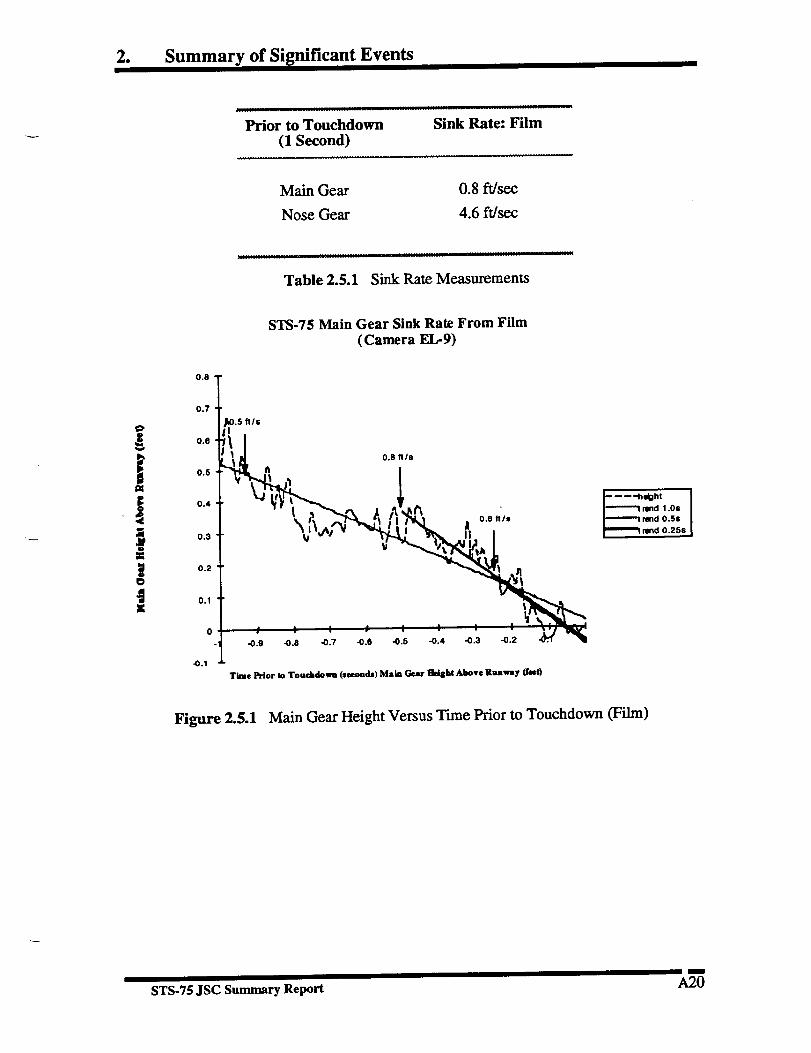
Landing Sink Rate Analysis (Task #3)
The main gear sink rate of the Orbiter was determined over a one second timeperiod prior to main gear touchdown using landing film. Nose gear sink rate wasdetermined over a one second time period prior to nose gear touchdown using
landing film
The measured main gear values were found to be below the maximum allowablevalues of 9.6 ft/sec for a 211,000 lb. vehicle and 6.0 ft/sec for a 240,000 lb.
vehicle (the landing weight of the STS-75 Orbiter was reported to be 228,500 lb.).The sink rate measurements for STS-75 are given in Table 2.5.1. In Figure 2.5.1the trend of the measured data points for film image data are illustrated.
I
STS-75 JSC Summary Report A19

2. Summary of Significant Events
.................... JL it iii .
Prior to Touchdown Sink Rate: Film
(1 Second)
Main Gear 0.8 ft/sec
Nose Gear 4.6 ft/sec
Table 2.5.1 Sink Rate Measurements
!O
K
STS-75 Main Gear Sink Rate From Film
(Camera EL-9)
Tkme Prior to Touchdown (secoads) Main Gear lldsbt Above Runwsy (feet)
""-'_d1.0$_dO.5s_d0.25$
Figure 2.5.1 Main Gear Height Versus Tune Prior to Touchdown (Film)
I
STS-75 JSC Summary Report A20

2. Summary of Significant Events
4O
2
J0
STS-75 Nose Gear Sink Rate From Film
(Camera El,-12)4.4 ftls
<:,.,,,.
, , , , , ",,
-0.9 -0.8 -0.7 -0.6 -0.5 -0.4 -0.3 -0.2 -0.1 0
Time Prior to Touchdown (seconds) Nose Gear I]kight Above Runway (feet)
Figure 2.5.2 Nose Gear Height Versus Time Prior to Touchdown (Film)
OTHER
Normal Events
Other normal events observed include: Vapor from the ET vent louver, inboard
elevon motion at SSME ignition, flares in SSME exhaust at SSME ignition, RCSpaper debris at SSME ignition through liftoff, vapor and ice from the TSM T-0disconnect areas during liftoff, ice and vapor from the ET/Orbiter umbilicals from
SSME ignition through liftoff, ET twang, acoustic waves at liftoff, pad debrisduring SSME ignition through liftoff, flame duct debris at liftoff, debris in the
•exhaust cloud after liftoff, vapor off the SRB stiffener rings after liftoff,outgassing of the El" aft dome, charring of the ET aft dome, roll maneuver,forward RCS paper detaching after the roll maneuver, slight body flap motion,expansion waves after the roll maneuver, Condensation around the launch vehicle,
SRB plume brightening prior to SRB separation, linear optical effects, SRBseparation.
Normal events seen that are related to the pad are hydrogen ignitor operation,fixed service structure (FSS) deluge water activation, GH2 vent arm retraction,sound suppression water initiation, mobile launch platform (MLP) water dumpactivation, LH2 and LO2 TSM T-0 umbilical disconnect, TSM door closure atliftoff.
I
STS-75 JSC Summary Report A21

APPENDIX B. MSFC PHOTOGRAPHIC ANALYSIS SUMMARY


National Aeronautics and
Space Administration
George C. Marshall Space Flight CenterMarshall Space Flight Center, AL 35812
EP42 (96-14)Zez:y [C A:'_ 0'
March 21, 1996
TO:
FROM:
SUBJECT:
Distribution
EP42/Thomas J. Rieckhoff
Engineering Photographic Analysis Report for STS-75
The launch of space shuttle mission STS-75, the nineteenth
flight of the Orbiter Columbia occurred on February 22, 1996, at
approximately 2:18 P.M. Central Standard Time from Launch
Complex 39B (LC-39B), Kennedy Space Center (KSC), Florida.
Photographic and video coverage was evaluated to determine
proper operation of the MSFC related flight hardware.
Film was received from fifty-four requested cameras as well
as video from twenty-four requested cameras. All ground based
cameras appeared to operate properly. Long-range tracking
camera coverage was degraded due to the high atmospheric
moisture content.
The astronauts recorded seven images of the ET after
separation using a hand-held 35mm camera The -Z side of the
tank was imaged. Backlighting of the tank provided reduced
data, The 35mm camera in the LO2 umbilical-well imaged up to
the intertank region since no +X translation was performed.
The following observations were made. The typical events
of ice/frost falling from the 17" disconnects at SSME ignition
and liftoff, butcher paper falling from the vehicle and debris
induced streaks were noted.
A holddown post stud hang-up was observed at post M-5 at
liftoff. The stud appeared to remain fully extended until
becoming free of the aft skirt.
Two streaks were observed in the plume of SSME #I during
liftoff at 20:18:00.645 and 20:18:01.016 UTC. These streaks
appeared to be attached to the exit plane of the nozzle
indicating internal sources.
A small thin piece of debris of unknown origin was observed
falling through the field-of-view of camera E-18.
BI

Several flashes were observed in the SSME plumes duringascent. These flashes are believed to be a result of debris
entrainment.
The 35mm LO2 umbilical-well camera recorded three divots at
the LH2 tank/intertank scarf joint near the -Y axis and one
divot at the scarf joint near the +Y axis.
The following event times were acquired.
EVENTM-I PIC Firing
M-2 PIC Firing
M-5 PIC Firing
M-6 PIC Firing
SRB separation
T_ME (UTC)
20:18:00.012
20:18:00.013
20:18:00.014
20:18:00.014
20:20:06.33
DATA SOURCECamera E-9
Camera E-8
Camera E-12
Camera E-13
Camera E-208
This report and additional information are available on the
World Wide Web at URL:
http://photo4.msfc.nasa.gov/STS/sts75/sts75.html.
For further information concerning this report contact Tom
Rieckhoff a_ 544_7677 or Jeff Hixson, Rockwell at 971-3082.
s ff
Enclosure
82
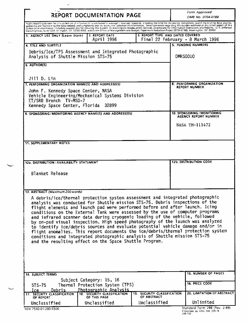
REPORT DOCUMENTATION PAGEForm Approved
OMB No. 0704-0188
Public repoFtlng burden for this collection of Jnformation Is estlrnated to average I hour per response, intruding the time for reviewing instructions, searching existing data source_,
gathering an_ maintaining the data needed, and completing and rewew_ng the collection of reformation. Send comments regarding this burden estimate or any other aspect of this
c0)lectlon of informat=on, _ncluding suggestions for re<_ucing this buraen, to WashmcJton Headaua_ers Servl(:e$, Oirectorate for Information Ol:_'ratlons and Reports, 1215 Jeffer'_on
Davis Highway, Subte 1204, Arlington, '_'A 222024302, and to the Office of Management and Budget, Paperwork Reduction Project (0704-0188), Washington, DC 20503
1. AGENCY USE ONLY_eave blank) |2. REPORT DATE
I April 1996
4. TITLE AND SUBTITLE
Debris/Ice/TPS Assessment and IntegratedAnalysis of Shuttle Mission STS-75
6. AUTHOR(S)
7.
Jill D. Lin
PERFORMINGORGANIZATIONNAME(S)AND ADDRESS(ES)
John F. Kennedy Space Center, NASAVehicle Engineering/Mechanical SystemsET/SRB Branch TV-MSD-7Kennedy Space Center, Florida 32899
3. REPORT TYPE AND DATES COVEREDFinal 22 February -8 March 1996
Photographic
Division
9. SPONSORING/MONITORING AGENCY NAME(S) AND ADDRESS(ES)
5. FUNDING NUMBERS
OMRSOOUO
8. PERFORMING ORGANIZATIONREPORT NUMBER
10. SPONSORING / MONITORINGAGENCY REPORT NUMBER
NASA TM-II1472
11. SUPPLEMENTARY NOTES
12a. DISTRIBUTION /AVAILABILITY STATEMENT
Blanket Release
12b, DISTRIBUTION CODE
13. ABSTRACT (Maximum 200 words)
A debris/ice/thermal protection system assessment and integrated photographic
analysis was conducted for Shuttle mission STS-75. Debris inspections of the
flight elements and launch pad were performed before and after launch. Icingconditions on the External Tank were assessed by the use of computer programs
and infrared scanner data during cryogenic loading of the vehicle, followed
by on-pad visual inspection. High speed photography of the launch was analyzedto identify ice/debris sources and evaluate potential vehicle damage and/or in
flight anomalies. This report documents the ice/debris/thermal protection systemconditions and integrated photographic analysis of Shuttle mission STS-75
and the resulting effect on the Space Shuttle Program.
_. SUBJECT TERMS
Subject Category: 15, 16
STS-75 Thermal Protection System (TPS)
I_. SECURITY CLASSIFICATION
OF REPORT OF THIS PAGE I
Unclassified Unclassified [NSN 7540-01-280-5500
19. SECURITY CLASSIFICATIONOF ABSTRACT
Uncl assi fied
_'. NUMBER OF PAGES
16. PRICE CODE
20. LIMITATION OF ABSTRACT
Unlimited
Standard Form 298 tRey 2-89)Prescribed by ANSi Std Z3(.I-18
298-102

J
t
KSC DEBRISflCE/TPS ASSESSMENT AND INTEGRATED PHOTOGRAPHIC ANALYSISREPORT DISTRIBUTION LIST 9/95
NASA - KSC
MK/L. J. ShriverTE-COM-2/C. BrownTV-PEO-2/R. HarrisonTV-MSD/C. Stevenson
TV-MSD-7/G. Katnik (7)RO-SLQ-3/J. L. Shehane
GK-5/Z. H. Byrns
SK-LOS/J. MartinLSO-321/H. L. LamberthLSO-437/M. Valdivia
ZK-88/K. J. MayerBICO-RVITS/R. B. HooverMMC- 15/D. S. OttoUSBI-LSS/L. Clark
NASA - HQ
QSO/W. Comer
NASA - JSC
EP2/B. RosenbaumES3/J. Kowal
FA22/D. CampSN3/E. ChristiansenSN5/M. Gaunce
NASA - MSFC
ED31/D. AndrewsEE31/M. A. Pessin
EE31/C. A. SnoddyEP24/T. J. Rieckhoff
Johnson Space CenterHouston, Texas 77058
Marshall Space Flight CenterHuntsville, AL 35812
Rockwell - Downey
AE2 l/J. McClymondsFA44/R. Ramon
Rockwell International12214 Lakewood Blvd
Downey, CA 90241
Martin Marietta
Dept. 3571/S. CopseyDept. 4200/P. Lewis
13800 Old Gentilly RoadNew Orleans, Louisiana 70129
P. O. Box 29304
New Orleans, Louisiana 70189