Dear Valued Customer, - New and Used Ophthalmic...
121
Transcript of Dear Valued Customer, - New and Used Ophthalmic...


Dear Valued Customer,
Congratulations on acquiring the new Accura Edger. We appreciate and thank
you for the confidence you have entrusted in our name.
This Edger has been manufactured with the greatest of care and inspected to
meet the most rigorous Briot standards. We recommend you read this manual,
carefully, for the proper use and enhancement of the life of your new equipment.
Please, keep it in a safe place for future reference.
As with all mechanical and electronic devices, however, your Briot machine will
require periodic adjustments, routine maintenance, and eventually the
replacement of certain hard-working parts. To ensure that your Briot unit is
continually operating at peak efficiency, it will be beneficial to have your unit
periodically inspected by an authorised Briot service representative.
Once again, thank you for choosing Briot.
The information contained in this manual are not contractual and can be
modified without notice. On top of that, errors and omissions can occur,
although all is performed to avoid them.
Briot does not assume any responsibilities or liabilities for damages
caused by errors or omissions.
BRIOT INTERNATIONAL
2, rue Roger Bonnet - BP 8
27340 PONT DE L'ARCHE
FRANCE
Tel. : (33) 02 32 98 91 32
Fax : (33) 02 35 02 02 94

Table of Contents
Issue: July 2003 Reference: FC 00 456-02


Accura Cx & Pro
Table of Contents iii
Table of Contents
1 Installation/Preparation Main Controls and Components.....................................................................................1-3 Unpacking Machine......................................................................................................1-4 Safety Precautions.......................................................................................................1-7 Installing the Machine...................................................................................................1-8
2 System Introduction Keypad .......................................................................................................................2-3 Scanform™ Scanner ....................................................................................................2-6 Basic Concepts ...........................................................................................................2-7
3 Scanning Scanning Mode............................................................................................................3-3 Frame Shape Scanning ................................................................................................3-5 Pattern or Demonstration Lens Shape Scanning .............................................................3-7
4 Layout/Blocking Layout/Blocking Mode..................................................................................................4-3 Layout and Blocking the Lens .......................................................................................4-5
5 Edging Edging Mode ...............................................................................................................5-3 Edging a Lens .............................................................................................................5-6 Controlled Bevel.........................................................................................................5-10 Controlled Groove.......................................................................................................5-13 Retouching a Lens .....................................................................................................5-15
6 System Adjustments Edging Wheel Differential Adjustment ............................................................................6-3 Frame Correction Adjustment........................................................................................6-4 User's Language Selection............................................................................................6-5 Using Level Selection ...................................................................................................6-6 Enable/Disable the Aestheticism Control........................................................................6-7 Enable/Disable the Retouch control ...............................................................................6-8 Screen Contrast Adjustment .........................................................................................6-9 Scanform Set-up........................................................................................................6-10 Wheel Dressing .........................................................................................................6-18 Size Adjustment (reset sizes).....................................................................................6-19 Wheel Counters Consultation......................................................................................6-20 Adjusting the Scanform Unit........................................................................................6-23 Lens Feelers Adjustment ............................................................................................6-28
7 System Cleaning Cleaning the Edger.......................................................................................................7-3
8 Maintenance Scanform messages ....................................................................................................8-3 Edger messages..........................................................................................................8-5

Accura Cx & Pro
iv Table of Contents
Table of Contents (continued)
Appendix A Installing a Recirculating System Installing a Recirculating System.................................................................................. A-3 Cleaning the Pump Recirculating System...................................................................... A-4
Appendix B Functioning with Memory Board & Network Connection Bar Code Reader ........................................................................................................ B-3 Memory Extension Circuit Board .................................................................................. B-4 Communication Extension Circuit Board ....................................................................... B-9
Appendix C Specifications Specifications: Accura Cx & Pro .................................................................................. C-3 Specifications: Accura Cx............................................................................................ C-5 Specifications: Accura Pro........................................................................................... C-6
Accura Cx & Pro
Table of Contents v
Evolution in relation to the previous version
This manual brings you the following information regarding the V3.70 and V3.71 Accura programs.
Page(s) New releases / Modification
2-3 key
2-4 key
2-6
key
5-5 Hydrophobic (water repellent) lenses
5-6 Warning: risk of collision of the adapter with the wheels
5-8 Safety mode
5-12, 5-14, 5-15 Hold the key to clamp
8-7 to 8-10 New messages

1 Installation/Preparation


Accura Cx & Pro
Installation/Preparation 1 - 3
Main Controls and Components
Diagram
Edging Station
Scanform™
Layout/Blocking Device
Accura Cx & Pro
1 - 4 Installation/Preparation
Unpacking Machine
Warning
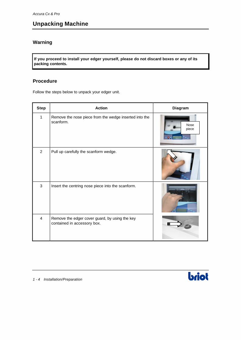
If you proceed to install your edger yourself, please do not discard boxes or any of its packing contents.
Procedure
Follow the steps below to unpack your edger unit.
Step Action Diagram
1 Remove the nose piece from the wedge inserted into the scanform.
Nosepiece
2 Pull up carefully the scanform wedge.
3 Insert the centring nose piece into the scanform.
4 Remove the edger cover guard, by using the key contained in accessory box.

Accura Cx & Pro
Installation/Preparation 1 - 5
Unpacking Machine (continued)
Procedure (continued)
Step Action Diagram
5 Unscrew and remove the Allen screw from the carriage shipping flange.
6 Remove the carriage flange. -
7 Remove the wedge located between the chassis and the carriage.
8 Remove the wedge of the lifting jack head.
9 Loosen and remove the nut and the two washers of the threaded rod coming from the left of lifting jack.
10 Remove the lifting jack wedge and its rod inserted in the translation tube.

Accura Cx & Pro
1 - 6 Installation/Preparation
Unpacking Machine (continued)
Procedure (continued)
Step Action Diagram
11 Remove the wedge located between the safety-bevel motor and the edging chamber.
12 Remove the stopper located at the rear of the machine in order to get access to the concerned screw.
13 Bring the carriage on the extreme left side (Operator located behind the machine).
14 Check the set screw of the gear A is lined up with the hole. If not, turn the gear in order to get to this situation.
Important: Before tightening the screw, the 1 & 2 marks on the small gear and 3&4 on the large gear must be lined up (make several turns if needed).
15 Put a 2-mm Allen wrench into the screw.
16 Tighten the screw strong.
Opening inthe rear cover
Stopper
Gear A
2mm AllenWrench
17 Put back the edger cover guard, by using the key contained in accessory box.

Accura Cx & Pro
Installation/Preparation 1 - 7
Safety Precautions
Warning
1 For the Accura Pro, before any operation on the machine (installation or servicing), check that main power switch is off and power plugs are both (Accura and inverter) not inserted in wall socket.
2. Do not place the edger near or on top of a source of energy (radiator or heater).
3. Make sure your voltage source corresponds to the voltage specified on edger nameplate, located on the rear of the machine .
4. If the machine is not going to be used for a long period of time you should unplug the power cords from the wall outlet.
• The external inverter for use with the Accura must be the Listed Telemecanique Inverter, model ATV18U29M2 or Leroy Somer, model SE 2.5M/TL BRE.
• The inverter is delivered complete, with cables, plugs, strain relieves, correct configuration and tested by the manufacturer.
• Please note that no field servicing is permitted for this unit.
Briot does not assume any responsibilities or liabilities for damages caused by negligence or ignoring the safety precautions enlisted in this manual.

Accura Cx & Pro
1 - 8 Installation/Preparation
Installing the Machine
Installation Conditions
Before installing the machine, make sure the bench is made up of the following components:
1. The bench
The bench receiving the machine must steady and leveled and be made up of a foot print of about 800 x 700 mm.
2. The electricity
• Accura Cx: 1 power outlet: 2P+T - 16 A - 220 V or 110 V protected with differential breaker of 30 mA. The outlet must be connected to the EARTH.
• Accura Pro: 2 power outlets: 2P+T - 16 A - 200 V–240 V protected with differential breaker of 30 mA. The outlets must be connected to the EARTH.
3. The water
• A water supply with a stop faucet equipped of a male connector 20x27 mm. This faucet must be kept for the machine and drilled at 80 cm maximum from the place excepted for the machine. The access must be easy and the faucet must be turn off when the machine is not used.
For a well functioning of the machine, the maximum water supply pressure must be between 4 and 7 bar.
• A water draining of ∅ 80 mm or higher. For proper drainage slope, angle pitch should be at least 5 %.
• For machine type Polycarbonate , provide a place under the machine with a minimum of 600w x 510h x 460d mm to place the water container.
4. The pump
Briot supplies pump system especially made for required water supply to Accura and for filtering of the edging waste. The pump dimensions are as follows:
• Dimensions:
• Width: 600 mm (24”)
• Depth: 400 mm (16”)
• Height: 800 mm (32”).

Accura Cx & Pro
Installation/Preparation 1 - 9
Installing the Machine (continued)
Bench Preparation
Follow the steps below to prepare the bench.
Step Action
1 Drill the bench as follows.
598 mm
305 mm
270 mm∅ 120 mm
660 mm
Bench
Edger
2 Drill the drain water hole(s).
3 Place the edger on the bench by positioning it in relation to the drilled holes.
Installation
Follow the steps below to install the machine.
Step Action Diagram
1 Level the machine by screwing or unscrewing the four feet.
2 Plug the drain pipe to the chassis of the machine.

Accura Cx & Pro
1 - 10 Installation/Preparation
Installing the Machine (continued)
Installation (continued)
Step Action Diagram
3 Connect the drain pipe(s) to the machine and to the faucet or the pump. Please refers to Appendix A for pump installation important notice.
Note: In case of installation on direct water only, add a filter joint contained in the accessory box.
4 Check that the main switch of the machine is on OFF position.
5 Connect the machine to the power outlet.
6 For the Accura Pro, connect the inverter as follows:
1. Connect the inverter control cable to the edger.
2. Connect the inverter power cable to the edger.
3. Fix the plate n° 11 22 165 (2x screws).
4. Fix the cable strain relief to secure the motor cable.
InverterControlCable
InverterPowerCable
7 For OMA machines, connect the edger to the OMA network and connect the bar code reader.
Bar CodeReaderConnector
OMA NetworkConnector
8 Mount the chucks and the centring nose piece (scanform) contained in the accessory box.
-
9 Remove the cover. -
10 Adjust the water flow by starting a cycle without lens. -

Accura Cx & Pro
Installation/Preparation 1 - 11
Installing the Machine (continued)
Installation (continued)
Step Action Diagram
11 Adjust each watering by acting on 1-2 and 3 solenoid valves (see paragraph Adjustments below).
1
2
3
12 Close the cover and make one or two jobs to check the well functioning of the machine.
-
Adjustments
Types Description
Main Water Spray (1) • Adjustable by operator.
• Must be sufficient to correctly lubricate the edging point.
Visor (2) • Not accessible by operator.
• Must be adjusted while installation.
Cleaning of the back of the edging station (Polycarbonate) (3)
Must be adjusted as follows:
• Water spray must be enough to remove the polycarbonate dust that hit the back of edging station (near the feelers).
• Water spray must not be too high to avoid a mist creation that can moisten the TP roughing wheel and create an undesired edging “in ribbon” of polycarbonate.

Accura Cx & Pro
1 - 12 Installation/Preparation
Installing the Machine (continued)
Installation of the bench
Accura
SpeedInverter
> 1,3 m
Pro Cx & Pro

2 System Introduction

Accura Cx & Pro
System Introduction 2 - 3
Keypad
Keys: Diagram
N° 000000000008
METAL
+70.38
Keys: Description
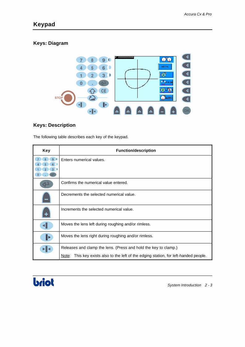
The following table describes each key of the keypad.
Key Function/description
Enters numerical values.
Confirms the numerical value entered.
Decrements the selected numerical value.
Increments the selected numerical value.
Moves the lens left during roughing and/or rimless.
Moves the lens right during roughing and/or rimless.
Releases and clamp the lens. (Press and hold the key to clamp.)
Note: This key exists also to the left of the edging station, for left-handed people.

Accura Cx & Pro
2 - 4 System Introduction
Keypad (continued)
Keys: Description (continued)
Key Function/description
Open the visor (inactive during edging cycle)
Corrects error while in entry process.
In combination with the following key:
• Consults wheel counters.
• Accesses to optician adjustment screens.
• Increases the screen contrast.
• Optician Size Adjustment equipped with digital calliper rule
(accuracy: 1/100mm).
• Decreases the screen contrast.
• Reverses the screen color.
• Gives a positive sign to a data input.
• Gives a negative sign to a data input.
Validates a function.
Does an emergency stop.
Unmarked key (Fct0 to Fct5), its meaning depends of the parameter displayed to the left of this key.
Unmarked key (Fct6 to Fct9), its meaning depends of the parameter displayed facing this key.

Accura Cx & Pro
System Introduction 2 - 5
Keypad (continued)
Initialisation Screen
On turning the machine starts and reads the following screen while the initialization cycle is running.
V01.00 V01.00# 0108 V01.00
ACCURA CX

Accura Cx & Pro
2 - 6 System Introduction
Scanform™ Scanner
Keyboard: Diagram
Keyboard: Description
The following table describes each key of the integrated scanform™ keyboard.
Key Description
Releasing and clamping the lens. (Press and hold the key to clamp.)
Note: Key established on this keyboard to be more accessible by left-handed people.
Setting and adjusting use only.
Setting and adjusting use only.
Setting and adjusting use only.
ON
Displays the message ON during regular operation. Setting and adjusting use only.
Interruption of Frame Shape Scanning.
Note: This key has a blinking red LED warning that an error has been detected on the scanform™.
Scanning Frame Shape.
Note: This key is linked with a green LED allowing to attract your attention to the necessity to press on this key to execute the shape scanning cycle.

Accura Cx & Pro
System Introduction 2 - 7
Basic Concepts
Three Working Modes
The edger makes three basic operations corresponding to a screen called "mode" that you can identify by a symbol located on right side of the screen.
Mode Screen Functions
Scanning (Blue background)
N ° 0 0 0 0 0 0 0 0 0 0 0 8
METAL
+70.38
Allows to enter the following parameters:
• Job Number
• Frame Type
• Lens Side to Scan
• Frame PD or Bridge
• Symmetry
• Scanning Type
Layout/ Blocking (Green background)
N ° 0 0 0 0 0 0 0 0 0 0 0 8
+62.00
∅∅ 45 ΠΠ
+28.00
28
Allows to enter the following parameters:
• Lens Side for Layout
• Vision Type
• Horizontal Decentration
• Height Decentration
• Segment Width for Near Vision
• Layout/Blocking Mode
• Height Reference.
Edging (Ochre background)
N ° 0 0 0 0 0 0 0 0 0 0 0 8 ΠΠ
+00.00
ORGANIC
Allows to enter the following parameters:
• Lens Side to Edge
• Lens Type to Edge
• Lens Finishing Type
• Bevel/Grooving Type
• Lens Final Size
• Safety-Bevelings
• Edging Pressure
• Lens Polishing.

Accura Cx & Pro
2 - 8 System Introduction
Basic Concepts (continued)
Going One Mode to the Other
To go one mode to the other, press the following key until displaying the desired screen.
N ° 0 0 0 0 0 0 0 0 0 0 0 8
METAL
+70.38
The screens scroll in the following order:
1. Scanning Screen (blue):
2. Layout/Blocking Screen (green):
3. Edging Screen (ochre)
Current Job/Previous Job
• If your machine is not equipped with a memory extension circuit board, the buffer can contain two jobs (First-In/First-Out) being managed as follows.
Type Diagram Managing
Current Job: Job Number in Inverse Video
N° 000000000008
METAL
+70.38
Key:
• Access to the previous job, in the three modes.
Key:
• Creation of a new job and deletion of the previous job, in scanning mode.
• Inactive, in layout and edging modes.
Previous Job: Job Number in Normal Video
N ° 0 0 0 0 0 0 0 0 0 0 0 8
OPTYL
+66.20
Key:
• Inactive, in the three modes.
Key:
• Access to the current job, in the three modes.
• If your machine is equipped with a memory extension circuit board, see Appendix B Functioning with Memory Board & Scannet Network Connection to manage the memory.

3 Scanning

Accura Cx & Pro
Scanning 3 - 3
Scanning Mode
Function/Diagram
N ° 0 0 0 0 0 0 0 0 0 0 0 8 Fct0
Fct1
Fct2
Fct3
Fct4
Fct5
METAL
+70.38
Functions: Description
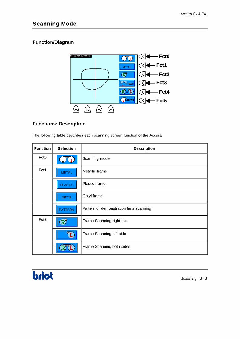
The following table describes each scanning screen function of the Accura.
Function Selection Description
Fct0
Scanning mode
Fct1 METAL
Metallic frame
PLASTIC
Plastic frame
OPTYL
Optyl frame
PATTERN
Pattern or demonstration lens scanning
Fct2
Frame Scanning right side
Frame Scanning left side
Frame Scanning both sides
Accura Cx & Pro
3 - 4 Scanning
Scanning Mode (continued)
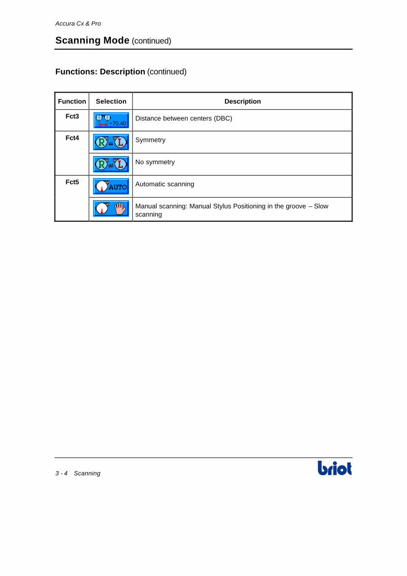
Functions: Description (continued)
Function Selection Description
Fct3 +70.40
Distance between centers (DBC)
Fct4
Symmetry
No symmetry
Fct5
Automatic scanning
Manual scanning: Manual Stylus Positioning in the groove – Slow scanning

Accura Cx & Pro
Scanning 3 - 5
Frame Shape Scanning
Procedure
Follow the steps below to scan the frame shape.
Step Action
1 Create a job number. To do this, press the key or enter a job number aid of the
keypad and press the key.
Note:
• If your machine is not equipped with a memory or communication extension circuit board, see paragraph Current Job/Previous Job of the Basic Concepts procedure in Chapter 2
• If your machine is equipped with a memory or communication extension circuit board, see Functioning with Memory Board & Scannet Network Connection in Appendix B.
2 Select the frame type: metallic, plastic or Optyl.
3 Select the side(s) to scan: right, left or both sides.
4 If necessary, select symmetry function.
5 Select the scanning type: Auto or Manual.
6 Press the key to validate the parameters.
7 Before scanning, clean the frame with an ultrasonic cleaning device.
Put the frame into the frame holder of the scanform™. 8
Check the eyewire joint is well closed (tighten the joint screw).

Accura Cx & Pro
3 - 6 Scanning
Frame Shape Scanning (continued)
Procedure (continued)
Step Action
9 Press the key of the scanform™ to scan the frame.
Result: When the scanning is finished, the shape is drawing on the screen.
N ° 0 0 0 0 0 0 0 0 0 0 0 8
METAL
+70.38
Scanning Interruption
In case of problems, you can stop the shape scanning cycle at anytime.
Step Action
1 Press the key of the scanform™.
Result: The scanning is stopped and the following message comes up.
N ° 0 0 0 0 0 0 0 0 0 0 0 8
+70.38
*****WARNING***** *****WARNING***** Origin : Scanform EO01 Type : Tracing aborted
Ok
Fct8
METAL
2 Press the Fct8 key.
Result: The message disappears from the screen.
Note: You can resume the scanning again. See previous procedure.

Accura Cx & Pro
Scanning 3 - 7
Pattern or Demonstration Lens Shape Scanning
Procedure
Follow the steps below to scan the pattern or demonstration lens shape.
Step Action
1 Create a job number. To do this, press the key or enter a job number aid of the
keypad and press the key.
Note:
• If your machine is not equipped with a memory or communication extension circuit board, see paragraph Current Job/Previous Job of the Basic Concepts procedure in Chapter 2
• If your machine is equipped with a memory or communication extension circuit board, see Functioning with Memory Board & Scannet Network Connection in Appendix B.
2 Select the PATTERN frame type.
3 Select the side to scan. To do this, follow the steps below.
If you scan… Then…
Left side 1. Press the key.
2. Insert the pattern placing the nasal part to the right or insert the right demonstration lens onto the pattern holder.
Patternholder

Accura Cx & Pro
3 - 8 Scanning
Pattern or Demonstration Lens Shape Scanning (continued)
Procedure (continued)
Step Action
3 (conti-nued)
Right 1. Press the key.
3. Insert the pattern placing the nasal part to the left or insert the left demonstration lens onto the pattern holder.
Patternholder
4 Select the symmetry function.
5 Select the scanning type: Auto or Manual.
6 • Place the lower part of the pattern holder in order to push away the nose of the pattern holder and to insert the lower pins between of the scanform clips.
• Make the top of the pattern holder rest on the upper jaw of the scanform in the positioning lugs.
7 Press the key of the scanform™
to start the scanning cycle.
Result: The frame scanning is in progress and the value of the bridge value is equal to zero.
N ° 0 0 0 0 0 0 0 0 0 0 0 8
PATTERN
+00.00
8 Enter a bridge value or a frame distance value.
Note: The machine interprets automatically the entered value as bridge or frame distance.
9 Remove the pattern holder.

4 Layout/Blocking

Accura Cx & Pro
Layout/Blocking 4 - 3
Layout/Blocking Mode
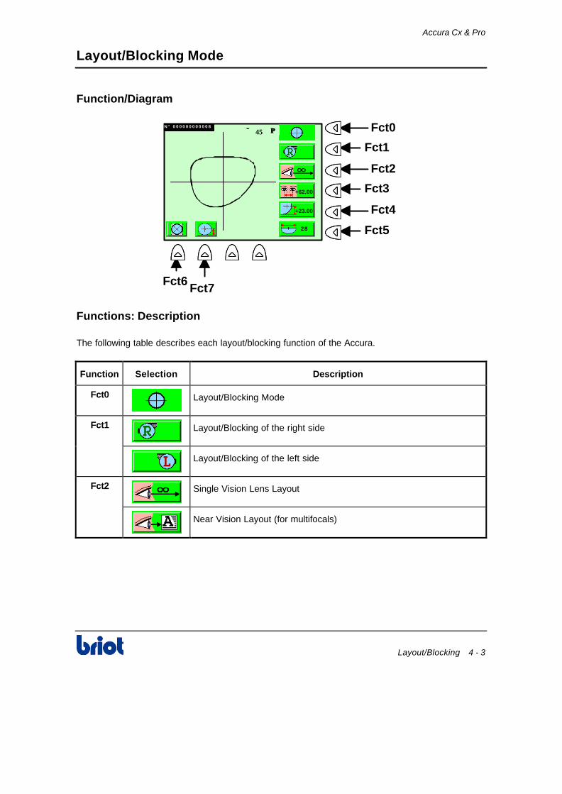
Function/Diagram
N ° 0 0 0 0 0 0 0 0 0 0 0 8 Fct0
Fct1
Fct2
Fct3
Fct4
Fct5
+62.00
Fct6Fct7
∅∅ 45 ΠΠ
+23.00
28
Functions: Description
The following table describes each layout/blocking function of the Accura.
Function Selection Description
Fct0
Layout/Blocking Mode
Fct1
Layout/Blocking of the right side
Layout/Blocking of the left side
Fct2
Single Vision Lens Layout
Near Vision Layout (for multifocals)

Accura Cx & Pro
4 - 4 Layout/Blocking
Layout/Blocking Mode (continued)
Functions: Description (continued)
Function Selection Description
Fct3 +06.00
Horizontal millimetric decentration
+30.00
Monocular Pupil Distance
+62.00
Binocular Pupil Distance
Fct4 +05.00
Vertical millimetric decentration: A vertical decentration height from the boxing center
+28.00
BOX height: From the pupil center, to the lowest point of the lens, at the bottom of the frame
+25.00
MIX height: The height is measured from where the pupil vertically aligns to the edge of the lens at the lower half of the frame
Fct5 28
Segment width
Fct6
Optical center: Lens is laid out and blocked on the optical center
Geometrical center: The optical center is displaced from the mechanical center
Fct7
BOX decentration: Height calculated from the optical center to the extreme bottom point of the frame
MIX decentration: Height calculated from the optical center to the frame point at the vertical of the optical center

Accura Cx & Pro
Layout/Blocking 4 - 5
Layout and Blocking the Lens
Procedure
Follow the steps below to layout and block the lens.
Step Action
1 Select the right or left lens to layout.
2 Select the vision type (see paragraph Comment & Layout Examples below).
3 Enter the pupil distance of the customer.
Result: The machine interprets automatically the entered value as a total pupil distance, monocular pupil distance or a decentration.
4 Enter the height of the optical center.
5 If necessary, enter the segment width for bifocals.
6 If necessary, select the centering mode.
7 If necessary, enter the height type.
8 Place a double-sided adhesive tape on a block.
You can use the blocks up to 125 times. Any use beyond this limit could lead to axis or distance problems whose Briot refuses all responsibilities.
9 Place the block inside the blocker of the machine.
10 Remove the protective paper from the tape.
Place and center the lens to be blocked on the screen according to the desired layout method (See Comment & Layout Examples paragraph below).
11
In case of thin or high cylinder lenses, place the lens holder ring contained in accessory box between the screen and the lens to hold and avoid it to break or move.
12 Press and hold the key to block the lens.

Accura Cx & Pro
4 - 6 Layout/Blocking
Layout and Blocking the Lens (continued)
Comment & Layout Examples
In case of doubt regarding the lens size for cut out, you can:
• Visually inspect the lens shape on the screen, under the lens blank to verify the lens blank is large enough or
• Compare the lens blank side diameter to the diameter value displayed at the top of the screen.
Example: ∅∅ 45
Lens Layout/Blocking Diagram
Single Vision: w/Raised Optical Center N ° 0 0 0 0 0 0 0 0 0 0 0 8
+62.00
∅∅ 45 ΠΠ
+23.00
28
Bifocal: w/28 mm Segment Width N ° 0 0 0 0 0 0 0 0 0 0 0 8
+62.00
∅∅ 45 ΠΠ
28
+15.00
Progressive: Laid out in Distance Vision N ° 0 0 0 0 0 0 0 0 0 0 0 8
+62.00
∅∅ 45 ΠΠ
+23.00
28

5 Edging

Accura Cx & Pro
Edging 5 - 3
Edging Mode
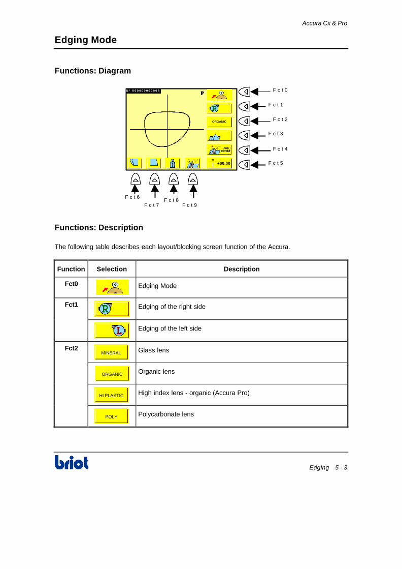
Functions: Diagram
N ° 0 0 0 0 0 0 0 0 0 0 0 8 ΠΠ F c t 0
F c t 1
F c t 2
F c t 3
F c t 4
F c t 5
F c t 6
F c t 7F c t 8
F c t 9
+00.00
ORGANIC
Functions: Description
The following table describes each layout/blocking screen function of the Accura.
Function Selection Description
Fct0
Edging Mode
Fct1
Edging of the right side
Edging of the left side
Fct2 MINERAL
Glass lens
ORGANIC
Organic lens
HI PLASTIC
High index lens - organic (Accura Pro)
POLY
Polycarbonate lens

Accura Cx & Pro
5 - 4 Edging
Edging Mode (continued)
Functions: Description (continued)
Function Selection Description
Fct3
Bevel finishing
Rimless finishing
Grooving Finishing
Warning: Grooving is not allowed on mineral lens.
Fct4
Front Side Bevel: The bevel is placed on the front side of the lens
1/3-2/3 Bevel: The bevel is placed at 1/3 of the front face and at 2/3 of the rear face of the lens
1/2-1/2 Bevel: The bevel is placed in the center of the lens
Rear Side Bevel: The bevel is placed on the rear side of the lens
Operator Bevel (Hand Symbol): The operator (see Controlled Bevel below) places the bevel
Esthetical bevel: Automatic bevel ; based on a 1/3 – 2/3 bevel, the machine places the bevel as much as possible to the front surface of the lens. The lens size is also adapted to the possible frame bending before lens fitting. Lens circumference and eye wire circumference are equal
Expert bevel: Automatic bevel ; the machine uses the frame curve to place the bevel and position it as much as possible to the front surface of the lens. Lens fitting without frame bending
Expert single groove: Automatic lens grooving – 0.6mm wide
Expert double groove: Automatic lens grooving – 1mm wide
Accura Cx & Pro
Edging 5 - 5
Edging Mode (continued)
Functions: Description (continued)
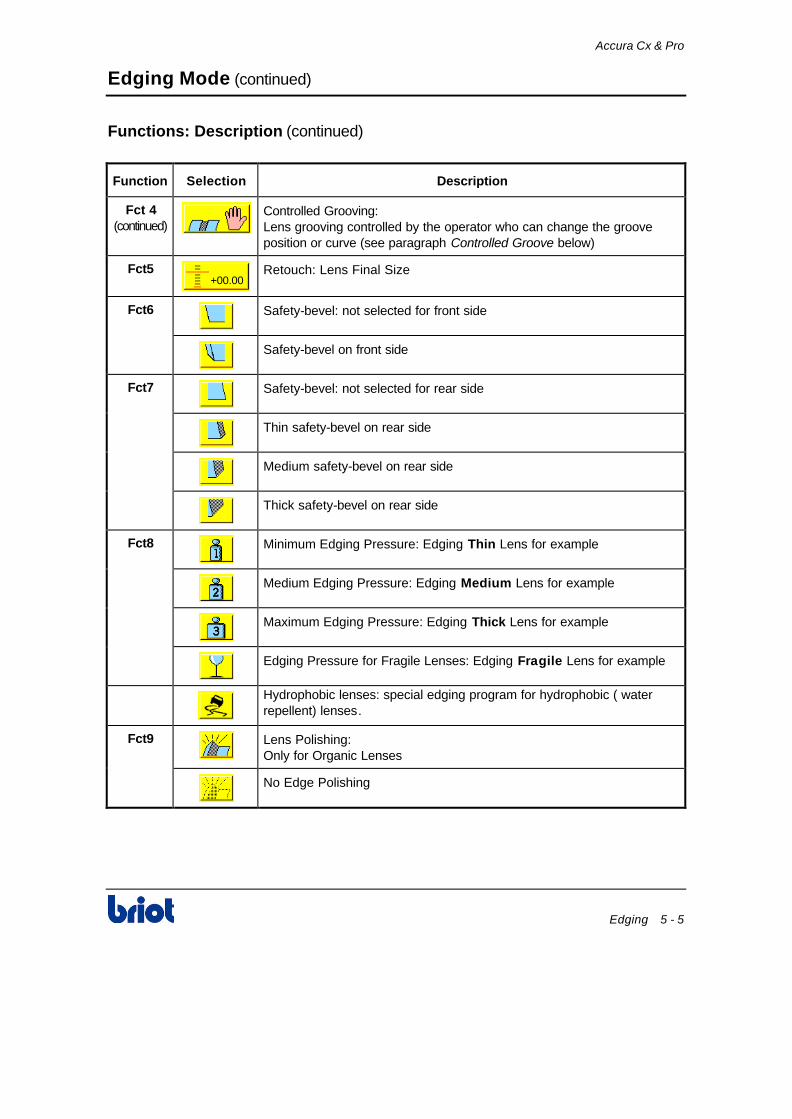
Function Selection Description
Fct 4 (continued)
Controlled Grooving: Lens grooving controlled by the operator who can change the groove position or curve (see paragraph Controlled Groove below)
Fct5 +00.00
Retouch: Lens Final Size
Fct6
Safety-bevel: not selected for front side
Safety-bevel on front side
Fct7
Safety-bevel: not selected for rear side
Thin safety-bevel on rear side
Medium safety-bevel on rear side
Thick safety-bevel on rear side
Fct8
Minimum Edging Pressure: Edging Thin Lens for example
Medium Edging Pressure: Edging Medium Lens for example
Maximum Edging Pressure: Edging Thick Lens for example
Edging Pressure for Fragile Lenses: Edging Fragile Lens for example
Hydrophobic lenses: special edging program for hydrophobic ( water repellent) lenses.
Fct9
Lens Polishing: Only for Organic Lenses
No Edge Polishing
Accura Cx & Pro
5 - 6 Edging
Edging a Lens
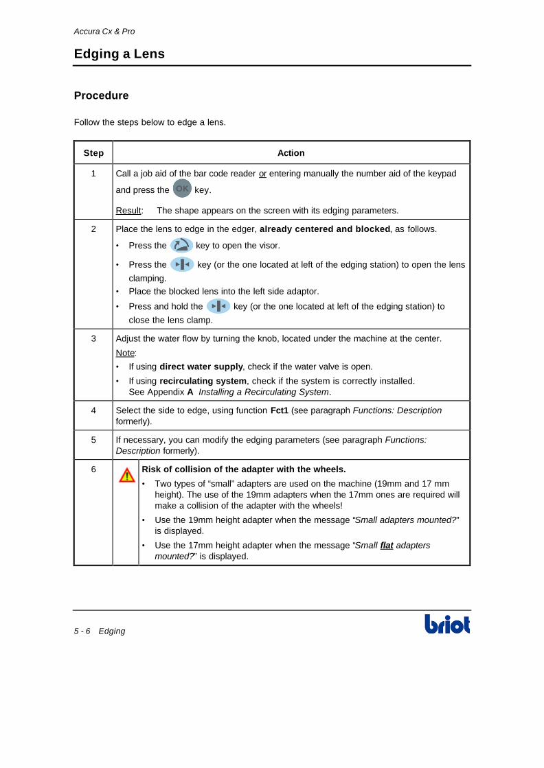
Procedure
Follow the steps below to edge a lens.
Step Action
1 Call a job aid of the bar code reader or entering manually the number aid of the keypad
and press the key.
Result: The shape appears on the screen with its edging parameters.
2 Place the lens to edge in the edger, already centered and blocked, as follows.
• Press the key to open the visor.
• Press the key (or the one located at left of the edging station) to open the lens
clamping.
• Place the blocked lens into the left side adaptor.
• Press and hold the key (or the one located at left of the edging station) to
close the lens clamp.
3 Adjust the water flow by turning the knob, located under the machine at the center.
Note:
• If using direct water supply, check if the water valve is open.
• If using recirculating system, check if the system is correctly installed. See Appendix A Installing a Recirculating System.
4 Select the side to edge, using function Fct1 (see paragraph Functions: Description formerly).
5 If necessary, you can modify the edging parameters (see paragraph Functions: Description formerly).
6 Risk of collision of the adapter with the wheels.
• Two types of “small” adapters are used on the machine (19mm and 17 mm height). The use of the 19mm adapters when the 17mm ones are required will make a collision of the adapter with the wheels!
• Use the 19mm height adapter when the message “Small adapters mounted?” is displayed.
• Use the 17mm height adapter when the message “Small flat adapters mounted?” is displayed.

Accura Cx & Pro
Edging 5 - 7
Edging a Lens (continued)
Procedure (continued)
Step Action
6 (continued) Press the key to start the edging cycle.
Result: The visor closes automatically and the edging cycle starts in the following order:
1. Roughing
2. Tracing
Do not open cover, during edging operation. Do not touch moving parts inside.
Result: If the uncut lens is too small for the shape, a message appears on the screen. Go to paragraph Lens Re-feeling below.
7 If you… Then...
Did not select the function
The bevel is automatic after roughing and lens feeling. Go to step 9 of this procedure.
Selected the function Go to paragraph Controlled Bevel below.
8 If you… Then...
Did not select the function
The bevel is automatic after roughing and lens feeling. Go to step 9 of this procedure.
Selected the function
Go to paragraph Controlled Groove below.
3. Finishing
4. Polishing (optional)
5. Safety-beveling (optional).
Result: After the edging cycle is complete, the visor opens automatically
9 Hold the edged lens and press the key of the keypad (or the one located at left of
the edging station) to open the right side chuck.
10 Remove the lens from the left side adaptor. Do not remove the block from the lens until the lens size has been confirmed with the optical frame.

Accura Cx & Pro
5 - 8 Edging
Edging a Lens (continued)
Safety mode
For the operator’s safety, some controls and actions have been implemented
Wheel rotation:
• The main motor starts only if the visor is closed
• The door opening key is inactive during the wheels rotation
• Opening manually the visor stops the wheel motor and switches the machine in error “visor function”
Clamping:
• To clamp the lens you have to hold the key until the clamping shaft gets in contact
with the lens.
• Releasing this key when clamping will automatically open the clamp.
• You have two seconds to release the key when the clamp is in contact with the lens
otherwise the clamp opens back if this delay is over.
• Starting the cycle with the clamp open will generate the warning message “Clamp the lens before start”
Cycle Interruption
The edging cycle can be interrupted at any time by pressing the key.
Result: The edging cycle stops immediately.
Edging a ½ Eye Lens
To edge a ½ eye lens you must:
1. Replace the standard chucks by the small chucks (∅ 19mm) located in the accessory box.
2. Proceed to edge as any other normal lens (see paragraph Edging a Lens formerly).

Accura Cx & Pro
Edging 5 - 9
Edging a Lens (continued)
Lens Re-feeling
Follow the steps below to re-feel a lens.
Step Action
1 When the message Lens too small for shape is displaying, press OK key.
Result: The following screen comes up.
1.48 2.97
4.45
ΠΠ
ΠΠ
Fct9
2 Press the Fct9 key to re-feel the lens 0.5 mm inside.
Note: You can re-feel the lens up to three times with 0.5 mm inner.
Result: If these three re-feelings are not still enough, the lens is too small, the machine can not edge it.
3 Start the finishing cycle. To do this, go to step 7 of paragraph Edging a Lens formerly.

Accura Cx & Pro
5 - 10 Edging
Controlled Bevel
Screen Description
1.48 2.97
4.45
ΠΠ
ΠΠ
Symbol Description
3 4
1 2
Developed curved of the lens
1. Back Side of Lens
2. Bevel Apex
edge and the bevel:
3. Front Side of Lens
4. Position Index
Move the bevel apex towards the back of the lens
Move the bevel apex towards the front of the lens
+ Pivot the bevel apex towards the back of the lens to current index position
+ Pivot the bevel apex towards the front of the lens to current index position
Position Index
4.45
1.48 2.971
3
2
Lens profile corresponding to the current index:
1. Bevel Position from Front
2. Bevel Position from Rear
3. Value of the lens thickness
→→ Move position index view of the lens clockwise
←← Move position index view of the lens counterclockwise
Select the bevel point whose position will be modified (opposite point is the pivot; it won’t move)
Allow the re-trace of the lens

Accura Cx & Pro
Edging 5 - 11
Controlled Bevel (continued)
Screen Description (continued)
Symbol Description
Allow the selection of the following bevel types:
Front Bevel
Rear Bevel
1/3 2/3 Bevel
1/2 1/2 Bevel
Expert bevel
Base Bevel identical to Frame Base
05 Defined Curve Bevel: modifying value (from 1 to 9) by
and/or keys
3-D Bevel: copies identical bevel as for the frame eye wire

Accura Cx & Pro
5 - 12 Edging
Controlled Bevel (continued)
Procedure
Follow the steps below to control the bevel position after roughing and feeling.
Step Action
1 After roughing and lens feeling cycles:
• Modify the bevel type if necessary, aid of the Fct5 key
Result: The new bevel position is released
• If necessary feel the lens again, aid of the Fct9 key.
1.48 2.97
4.45
ΠΠ
ΠΠ
Fct9
Fct5
2 Select the bevel point whose the position will be modified (opposite point at 180° won’t move).
3 Modify the bevel point on selected place, aid of the + and/or + keys.
4 Move forward the curved drawn by the bevel towards the front or the back, aid of the
and keys.
5 Sweep the lens around to display the lens section, aid of the and keys.
6 When the bevel position is correct, press the key to start edging.
Result:After the edging cycle, the visor opens automatically.
7 Hold the edged lens while pressing and holding the key of the keypad (or the one
located at left of the edging station) to open the right side shaft.
8 Remove the lens from the left side adaptor, making sure not to remove the block as some re-edging might be necessary for proper sizing of lens.

Accura Cx & Pro
Edging 5 - 13
Controlled Groove
Screen Description
1.48 2.97ΠΠ
ΠΠ
5.05
00
Symbol Description
3 4
1 2
Developed curved of lens slice
1. Back Side of Lens
2. Groove Center
and grooving centre position:
3. Front Side of Lens
4. Position Index
Move the groove towards the back (0.4 mm maximum)
Move the groove towards the front (0.4 mm maximum)
+ Pivot the groove towards the back of the lens
+ Pivot the groove towards the front of the lens
Position Index
5.05
1.48 2.971
3
2
Lens profile corresponding to the current index:
1. Front Side Distance from the front edge of the groove
2. Rear Side Distance from the back edge of the groove
3. Value of the lens thickness
→→ Move position index view of the lens clockwise
←← Move position index view of the lens counterclockwise
Select the groove point whose position will be modified (opposite point is the pivot; it won't move)
Re-feel the lens
or Select the simple groove type (thickness: 0.6 mm) or the double groove type (thickness: 1mm, jobs with metal wire)
Automatic lens grooving

Accura Cx & Pro
5 - 14 Edging
Controlled Groove (continued)
Procedure
Follow the steps below to control the lens grooving.
Step Action
1 After roughing and lens feeling cycles, select:
• The grooving type, aid of the Fct5 key.
• The groove base, aid of the and/or .keys.
1.48 2.97ΠΠ
ΠΠ
5.05
00
Fct5
2 Select the grooving point whose the position will be modified (opposite point at 180° won’t move).
3 Modify the grooving point on selected place, aid of the + and/or +
keys.
4 Move forward the curved drawn by the grooving towards the front or the back, aid of the
and keys.
5 Sweep the lens around to display the lens section, aid of the and keys.
6 When the grooving position is correct, press the key to start rimless, polishing (possibly) then grooving cycles.
Result: After the edging cycle, the visor opens automatically.
7 Hold the edged lens while pressing and holding the key of the keypad (or the one
located at left of the edging station) to open the right side shaft.
8 Remove the lens from the left side adaptor, making sure not to remove the block, as some re-edging might be necessary for proper sizing of lens.

Accura Cx & Pro
Edging 5 - 15
Retouching a Lens
Prerequisites
Before retouching a lens, make sure of the following:
• The lens block has not been removed from its original lens placement
• The edging parameters have not been altered.
Procedure
Follow the steps below to retouch a lens after edging.
Step Action
1 Place the lens in the edger again.
2 If the lens to retouch comes from the previous job, press the key, if not go to the
following step.
3 Select the side to retouch aid of the Fct1 key.
4 Press the Fct5 key.
Result: The size value appears in inversed color.
N ° 0 0 0 0 0 0 0 0 0 0 0 8 ΠΠ
Fct5+00.00
Fct1
ORGANIC
5 Enter the value to reduce the size, by:
• The keypad or
• The and/or keys.
Note: The correction value is always in a negative form and is limited to a minimum increment of 00.05 mm.
Warning: If the correction value is > to 0.1 mm then the safety-bevel won’t be performed.
6 Press the key.
Warning: The retouch cycle can be performed only when the correction value has been entered.
7 Hold the edged lens while pressing and holding the key of the keypad (or the one
located at left of the edging station) to open the right side shaft.

6 System Adjustments


Accura Cx & Pro
System Adjustments 6 - 3
Edging Wheel Differential Adjustment
Condition
To adjust the wheel differentials, the system must be in rest position (not in scanning or edging process).
Procedure
Follow the steps below to adjust edging wheel differentials.
Step Action
1 When you are in scanning mode , press simultaneously the and keys.
2 Press the key.
Result: The following screen comes up (default values).
Metal frame correction +00.00Plastic frame correction +00.30Optyl frame correction +00.50
+01.20Roughing differential before BvlRoughing differential before Rim +02.00Roughing differential before Pol. +00.20
Final size correction - 00.10Plastic correction +00.00Polycarbonate correction - 00.10Pattern correction +00.00
3 Press the key until the appropriate value is highlighted.
Result: The selected value is displaying in inverse colour.
4 Enter the value of the desired wheel differential aid of the keypad.
5 Press the key to validate your entry.
6 Go to the step 3 of this procedure until you adjust all the necessary wheel differentials.
7 Press several times the key to get back to the working mode.
Accura Cx & Pro
6 - 4 System Adjustments
Frame Correction Adjustment
Condition
To adjust the frame correction, the machine must be in rest position (not in scanning or edging process).
Procedure
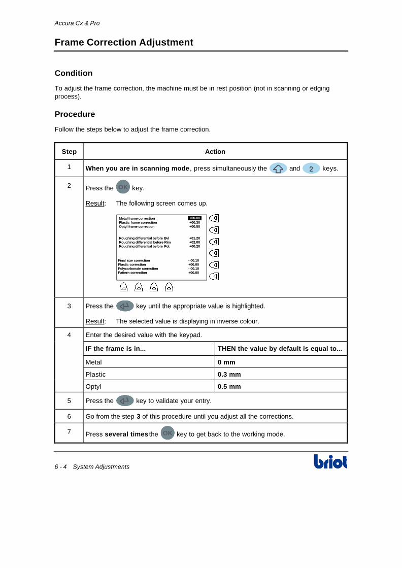
Follow the steps below to adjust the frame correction.
Step Action
1 When you are in scanning mode , press simultaneously the and keys.
2 Press the key.
Result: The following screen comes up.
Roughing differential before Bvl +01.20Roughing differential before Rim +02.00Roughing differential before Pol. +00.20
Metal frame correctionPlastic frame correction +00.30Optyl frame correction +00.50
+00.00
Final size correction - 00.10Plastic correction +00.00Polycarbonate correction - 00.10Pattern correction +00.00
3 Press the key until the appropriate value is highlighted.
Result: The selected value is displaying in inverse colour.
4 Enter the desired value with the keypad.
IF the frame is in... THEN the value by default is equal to...
Metal 0 mm
Plastic 0.3 mm
Optyl 0.5 mm
5 Press the key to validate your entry.
6 Go from the step 3 of this procedure until you adjust all the corrections.
7 Press several times the key to get back to the working mode.

Accura Cx & Pro
System Adjustments 6 - 5
User's Language Selection
Procedure
Follow the steps below to select the language.
Step Action
1 When you are in scanning mode , press simultaneously the and keys.
Result: The following screen comes up.
User’s language English
Level Expert
Aestheticism control Enable
SCANFORM ACCURAV05.00 # 0108 V01.00
Retouch controlPatent #97/15242 Enable
2 Press the key facing the line User’s language: English until you display the
desired language:
• English
• Français
• Español
• Italiano
• Deutsch
• Nederlands
• • Portugues
• Magyar
• • Norge
• Svenska
• Srpsko-HrvatskiI
• Suomen
• • Japanese
•
•
3 Press twice the key to get back to the working mode.
4 Switch the machine off then on to confirm the language changing.
Accura Cx & Pro
6 - 6 System Adjustments
Using Level Selection
2 Levels
The following table describes the 2 using levels of the machine.
Level Using Type
Expert (Default)
Intend to be used for more advanced functions of the machine such as lens layout/blocking (see paragraph Layout and Blocking the Lens in Chapter 4).
Novice Intend to be used for simple functions of the machine.
Procedure
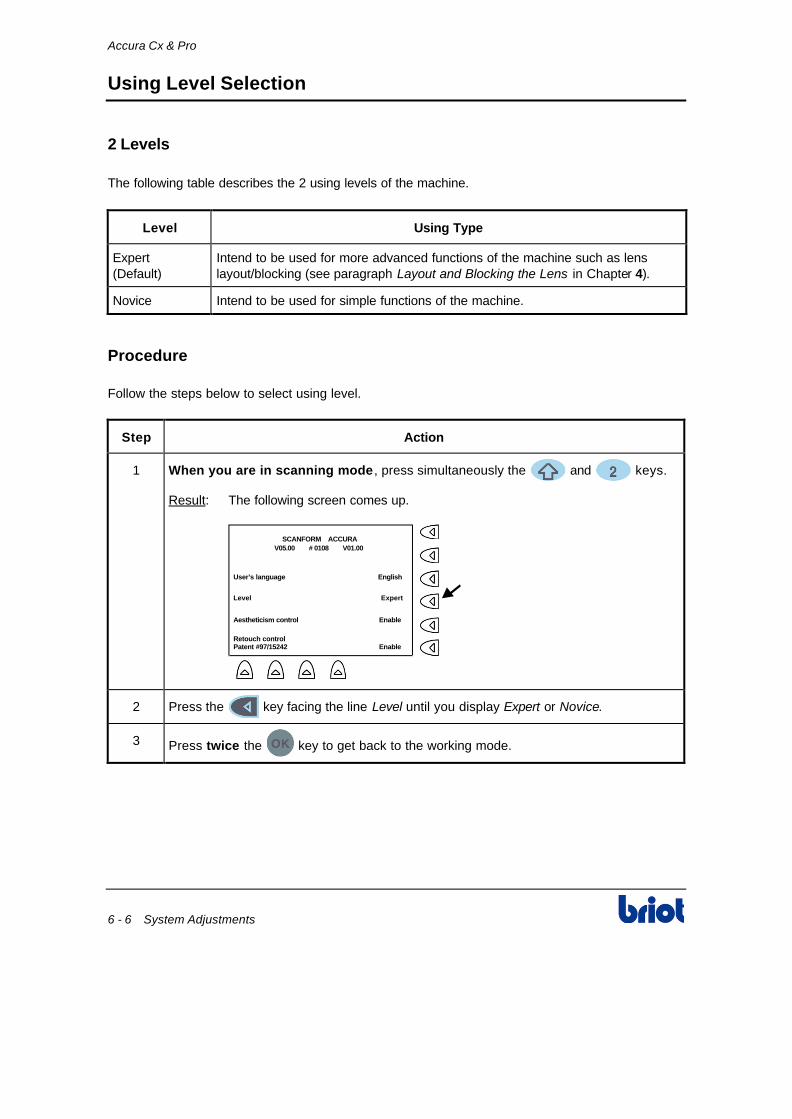
Follow the steps below to select using level.
Step Action
1 When you are in scanning mode , press simultaneously the and keys.
Result: The following screen comes up.
User’s language English
Level Expert
Aestheticism control Enable
SCANFORM ACCURAV05.00 # 0108 V01.00
Retouch controlPatent #97/15242 Enable
2 Press the key facing the line Level until you display Expert or Novice.
3 Press twice the key to get back to the working mode.

Accura Cx & Pro
System Adjustments 6 - 7
Enable/Disable the Aestheticism Control
Description
• If expert bevel has been selected, the machine performs a control of the bevel placement and alerts if the calculated bevel may result a non-aesthetic glazing.
• In that case, the edger displays the warning message "Aestheticism" and switch to the bevel control screen for an eventual modification of the base curve and/or the bevel position by the operator.
• This control is also performed in case of expert grooving selection. • It is possible to enable or disable the automatic control for any lens with the following procedure.
Procedure
Follow the steps below to enable/disable the Aestheticism test.
Step Action
1 When you are in scanning mode , press simultaneously the and keys.
Result: The following screen comes up.
User’s language English
Level Expert
Aestheticism control Enable
SCANFORM ACCURAV05.00 # 0108 V01.00
Retouch controlPatent #97/15242 Enable
2 Press the key facing the line Aestheticism control until you display Enable or
Disable.
3 Press twice the key to get back to the working mode.

Accura Cx & Pro
6 - 8 System Adjustments
Enable/Disable the Retouch control
Introduction
• The retouch control is a test procedure patented by Briot. When this system is activated, and when a lens retouch is programmed, the machine tests the lens in the machine is effectively the lens to retouch.
• This procedure increases the security control on the lens but also the process time. You can enable or disable this test.
Procedure
Follow the steps below to enable/disable the retouch control test.
Step Action
1 When you are in scanning mode , press simultaneously the and keys.
Result: According to the type of machine, the following screen comes up.
User’s language English
Level Expert
Aestheticism control Enable
SCANFORM ACCURAV05.00 # 0108 V01.00
Retouch controlPatent #97/15242 Enable
2 Press the key facing the line Retouch control until you display Enable or Disable.
3 Press twice the key to get back to the working mode.

Accura Cx & Pro
System Adjustments 6 - 9
Screen Contrast Adjustment
Description
There are 3 types of adjustment to improve visibility of the lens on the scanform™ screen.
Type Function Possible Use
Inverse Colour Key Improve the visibility of the bifocal segment
Bifocal Lens Layout
Screen Brightness Adjust the brightness of the recorded shape with the screen
Adapts to the ambient light in the working lab
Polarizing View Finder Adjust the contrast of the lens with the screen
Improves view when decentering of a dark lens
Inverse Colour
The inverse colour may be changed at any time, by pressing the and keys.
Result: The screen reverses colour.
Notes: The colour will default back to black on white after the system has been switched off.
To return to black on white, press again the and keys.
Screen Contrast Adjustment Keys
• + : Allow to darken the screen contrast
• + : Allow to lighten the screen contrast.
Polarizing Visor
To adjust the brightness of the recorded shape with the screen, rotate the polarizing eyepiece in either direction to suit you best.

Accura Cx & Pro
6 - 10 System Adjustments
Scanform Set-up
Purpose
This section provides you with the information required to change the screen contrast, the operator language and other setting.
Entering the Configuration Mode
To enter the configuration mode, proceed as follows.
Step Action
1 Turn on the Accura.
2 While the machine is initializing, press and hold down for approximately two
seconds. You must do so before the screen changes (loading bar disappears). Otherwise:
• Wait until the initialisation phase has finished
• Turn the Accura off and on again
• Repeat the procedure from step 1.
Result: The general menu is displayed.
CONFIGURATIONADJUSTMENTMTRCOUNTER
3
Press to enter the configuration mode.

Accura Cx & Pro
System Adjustments 6 - 11
Scanform Set-up (continued)
Exiting the Mode
To exit the configuration mode, proceed as follows.
Step Action
1 In the menu « CONFIGURATION », press to scroll down the menu until « Exit »
is displayed and press .
Result: The general menu is displayed.
2 In the general menu, press to scroll down the menu until « Exit » is displayed
and press .
Result: The scanform is back to normal operation.
Setting the screen contrast
To set the screen contrast, proceed as follows.
Step Action
1 Enter the « CONFIGURATION » menu as indicated in paragraph Entering the Configuration Mode formerly.
2
Select the mode « SCREEN CONTRAST » by pressing .
3 Adjust the screen contrast by pressing (clearer) or (darker).
4
When the contrast is correct, press .
5 Exit the menu « CONFIGURATION » as indicated in paragraph Exiting the Mode formerly.
Accura Cx & Pro
6 - 12 System Adjustments
Scanform Set-up (continued)
Setting the Operator Language
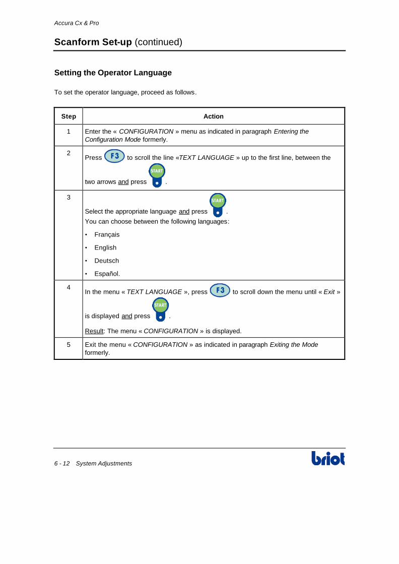
To set the operator language, proceed as follows.
Step Action
1 Enter the « CONFIGURATION » menu as indicated in paragraph Entering the Configuration Mode formerly.
2 Press to scroll the line «TEXT LANGUAGE » up to the first line, between the
two arrows and press .
3
Select the appropriate language and press .
You can choose between the following languages:
• Français
• English
• Deutsch
• Español.
4 In the menu « TEXT LANGUAGE », press to scroll down the menu until « Exit »
is displayed and press .
Result: The menu « CONFIGURATION » is displayed.
5 Exit the menu « CONFIGURATION » as indicated in paragraph Exiting the Mode formerly.

Accura Cx & Pro
System Adjustments 6 - 13
Scanform Set-up (continued)
Checking the communication protocol
To check the communication protocol, proceed as follows.
Step Action
1 Enter the « CONFIGURATION » menu as indicated in paragraph Entering the Configuration Mode formerly.
2 Press to scroll the line « PROTOCOL » up to the first line, between the two
arrows and press .
3
Check that the selected protocol is effectively « San4 ». If not, select it and press .
4 In the menu « PROTOCOL », press to scroll down the menu until « Exit » is
displayed and press .
Result: The menu « CONFIGURATION » is displayed.
5 Exit the menu « CONFIGURATION » as indicated in paragraph Exiting the Mode formerly.

Accura Cx & Pro
6 - 14 System Adjustments
Scanform Set-up (continued)
Activating / Deactivating the scanform security
To Activate / Deactivate the scanform security, proceed as follows.
Step Action
1 Enter the « CONFIGURATION » menu as indicated in paragraph Entering the Configuration Mode formerly.
2 Press to scroll the line « PHOTOCELL » up to the first line, between the two
arrows and press .
3
Activate or deactivate the security (ON or OFF) and press .
4 In the menu « PHOTOCELL », press to scroll down the menu until « Exit » is
displayed and press .
Result: The menu « CONFIGURATION » is displayed.
5 Exit the menu « CONFIGURATION » as indicated in paragraph Exiting the Mode formerly.
Accura Cx & Pro
System Adjustments 6 - 15
Scanform Set-up (continued)
Setting the stylus type
To set the type of stylus, proceed as follows.
Step Action
1 Enter the « CONFIGURATION » menu as indicated in paragraph Entering the Configuration Mode formerly.
2 Press to scroll the line « TIP VERSION » up to the first line, between the two
arrows and press .
3
Set the type of stylus present on your scanform and press .
You can select the following types:
• V1 (the second stylus tip will not be used)
• V3 (the second stylus tip will not be used)
4 In the menu « TIP VERSION », press to scroll down the menu until « Exit » is
displayed and press .
Result: The menu « CONFIGURATION » is displayed.
5 Exit the menu « CONFIGURATION » as indicated in paragraph Exiting the Mode formerly.

Accura Cx & Pro
6 - 16 System Adjustments
Scanform Set-up (continued)
Set the interface by icons
When using the tracer (Mode Scanform Net 2 only), the messages displayed on the screen (Type of frame, right or left side, etc.) can be replaced by explicit icons. This menu is to select whatever interface (text or icons).
To set the interface by icons, proceed as follows:
Step Action
1 Enter into the “ICON” menu.
2 Select and validate the option ON or OFF.
3 Exit from the “ICON” menu
Set the tracing speed
It is possible to modify the tracing speed of the tracer. The selection « Fast scan » (selection by default) will make the scanner to trace in fast speed. The selection « Slow scan » will make the scanner to trace in slow speed (speed is identical to the slow tracing selected on the keypad but the stylus insertion is automatic).
To set the tracing speed, proceed as follows:
Step Action
1 Enter into the “SCANNING SPEED” menu.
2 Select and validate the option « Fast scan » or « Slow scan ».
3 Exit from the “ SCANNING SPEED” menu.

Accura Cx & Pro
System Adjustments 6 - 17
Scanform Set-up (continued)
Set the calibration test
In order to guarantee a correct and constant scanform calibration, it is possible to start the procedure « Calibration test », see adj.3 each time the scanform is turned on. This check-up can be enabled or disabled.
To set the calibration test, proceed as follows:
Step Action
1 Enter into the “CALIBRATION TEST” menu.
2 Select and validate the option ON or OFF.
3 Exit from the “CALIBRATION TEST ” menu.
Enable / disable the display of the parameters
When adjusting the scanform, it is possible to display or not the adjustment parameters of the calibration step that has just been performed.
Not displaying the adjustment parameters can lead to a non detection of a latent problem laying in the scanform.
To enable or disable the display of the parameters, proceed as follows:
Step Action
1 Enter into the “ADJ. PARAM. DISP” menu.
2 Select and validate the option ON or OFF.
3 Exit from the “ADJ. PARAM. DISP” menu.

Accura Cx & Pro
6 - 18 System Adjustments
Wheel Dressing
Procedure
Follow the steps below to dress a wheel.
Step Action
1 When you are in scanning mode , press simultaneously the and keys.
Result: The following screen comes up.
Automatic dressing
Lens sizes adjustment
2 Select the line Automatic dressing.
3 Select the wheel to dress.
4 Load the dressing disk adapted to the wheel to dress, contained in the accessory box.
5 Press the OK key.
6 When the dressing is completed, remove the disk from the edger.
7 Press the Valide key.
8 Press several times the Esc key to quit the adjustment.
9 Adjust the sizes (see paragraph Size adjustment (reset sizes) below).

Accura Cx & Pro
System Adjustments 6 - 19
Size Adjustment (reset sizes)
Procedure
Follow the steps below to adjust the sizes.
Step Action
1 When you are in scanning mode , press simultaneously the and keys.
Result: The following screen comes up.
Automatic dressing
Lens sizes adjustment
2 Select the line Lens size adjustment.
3 Insert a lens with a diameter ≥≥ to 60 mm.
Adjustment Lens Using
1. Finishing Rimless Mineral
2. Mineral roughing Mineral
3. Plastic roughing Plastic
4. Finishing bevel Mineral
5. Polishing Rimless Plastic
6. Polishing Bevel Plastic
4 Press the OK key.
5 When the edging is completed, measure the diameter of the edged lens with a digital calliper.
6 Enter the measured value, with the and/or keys or with the keyboard.
7 Press the key to confirm the finishing rimless size adjustment.
8 Adjust the following size. Repeat from step 3 of this procedure.
9 When the size adjustment is completed, save your adjustment.
Accura Cx & Pro
6 - 20 System Adjustments
Wheel Counters Consultation
Procedure
Follow the steps below to consult the wheel counters.
Step Action
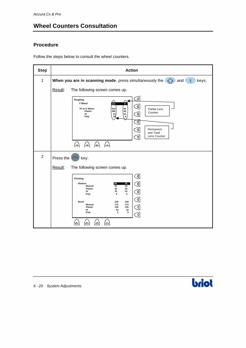
1 When you are in scanning mode , press simultaneously the and keys.
Result: The following screen comes up.
Roughing
F Wheel
TP or E Wheel 516 60Plastic 482 46Hi 10 10Poly 24 4
221 0
Partial LensCounter
Permanentand TotalLens Counter
2 Press the key.
Result: The following screen comes up.
Finishing
RimlessMineral 51 10Plastic 35 25Hi 10 10Poly 0 0
Bevel 318 318Mineral 173 173Plastic 135 135Hi 10 10Poly 0 0
96 45

Accura Cx & Pro
System Adjustments 6 - 21
Wheel Counters Consultation (continued)
Procedure (continued)
Step Action
3 Press the key.
Result: The following screen comes up.
Polishing
RimlessPlastic 35 25Hi 10 10Poly 0 0
Bevel 145 145Plastic 135 135Hi 10 10Poly 0 0
45 35
4 Press the key.
Result: The following screen comes up.
Safety bevel
Front sideMineral 3 3Plastic 6 6Hi 1 1Poly 0 0
Back side 0 0Mineral 0 0Plastic 0 0Hi 0 0Poly 0 0
10 10

Accura Cx & Pro
6 - 22 System Adjustments
Wheel Counters Consultation (continued)
Procedure (continued)
Step Action
5 Press the key.
Result: The following screen comes up.
Groove
Total 60 19Plastic 43 9Hi 10 10Poly 7 0
Double 4 1
Groove Number insimple width(Nylon wire)
Groove Number indouble width(Air-Titanium Type)
6 Press the key.
Result: The following screen comes up.
Retouch
RimlessMineral 0 0Plastic 0 0Hi 0 0Poly 0 0
Bevel 7 7Mineral 3 3Plastic 3 3Hi 1 1Poly 0 0
Retouch rate 0% 0%
0 0
7 Press the key to come back to the working mode.

Accura Cx & Pro
System Adjustments 6 - 23
Adjusting the Scanform Unit
Purpose
This section enables you to adjust the Scanform unit using the various tools supplied.
Running the Adjustment Procedure
This “Start” option will actually start the calibration procedure. It’s a step by step procedure, requiring the use of 4 specific tools, located into the user black box.
For safety purpose, previous calibration values will be preserved if the ongoing calibration fails before reaching it’s very end. Once fully performed, new calibration values will be taken into account, only if the “Save” option is chosen.
Step Action
1 Select Run and press .
Result: The initialisation sequence is performed.
2 When the icon comes up, insert the gain adjustment jig (shown below)
as requested and press .
Result: The icon comes up. You are asked to confirm the tool length engraved on the tool (default = 40.00 mm). You can change the length
in increments of 0.01 mm using and .
3 When the required length is displayed, press .
Result: The icon comes up. You are asked to confirm the tool height engraved on the tool (default = 24.00 mm). You can change the height
in increments of 0.01 mm using and .
Accura Cx & Pro
6 - 24 System Adjustments
Adjusting the Scanform Unit (continued)
Running the Adjustment Procedure (continued)
Step Action
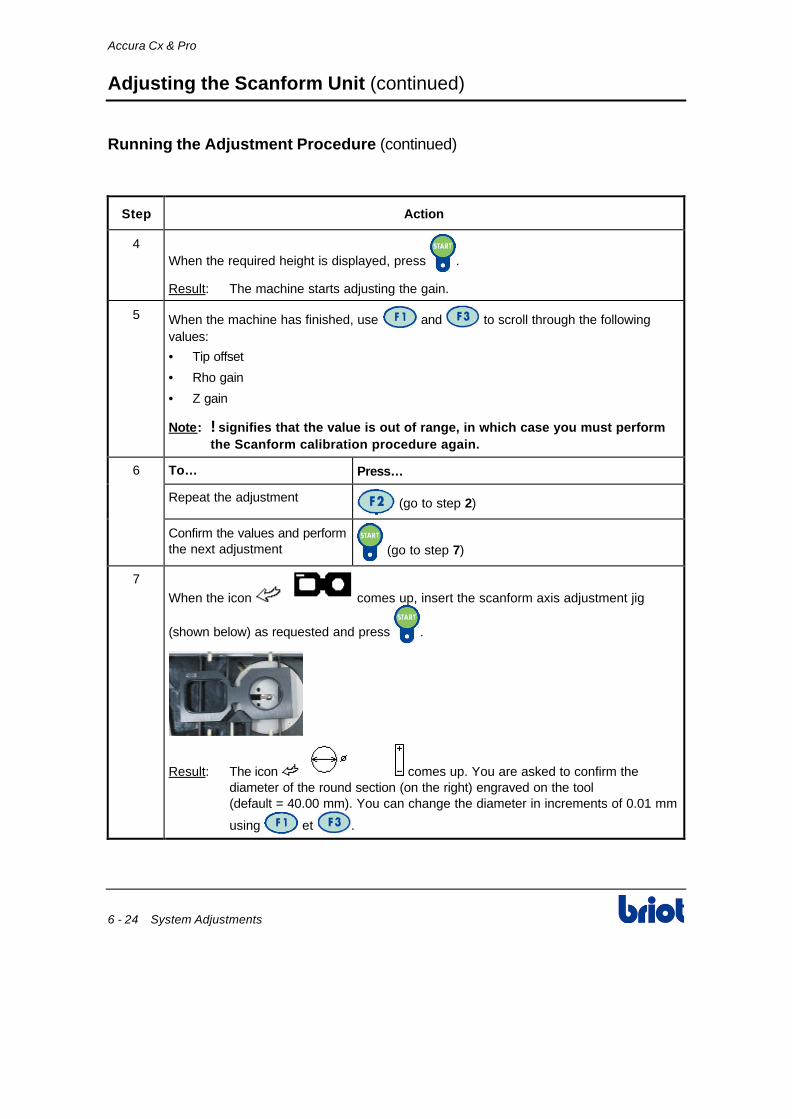
4 When the required height is displayed, press .
Result: The machine starts adjusting the gain.
5 When the machine has finished, use and to scroll through the following values:
• Tip offset
• Rho gain
• Z gain
Note: ! signifies that the value is out of range, in which case you must perform the Scanform calibration procedure again.
6 To… Press…
Repeat the adjustment (go to step 2)
Confirm the values and perform the next adjustment (go to step 7)
7
When the icon comes up, insert the scanform axis adjustment jig
(shown below) as requested and press .
Result: The icon comes up. You are asked to confirm the diameter of the round section (on the right) engraved on the tool (default = 40.00 mm). You can change the diameter in increments of 0.01 mm
using et .

Accura Cx & Pro
System Adjustments 6 - 25
Adjusting the Scanform Unit (continued)
Running the Adjustment Procedure (continued)
Step Action
8 When the required diameter of the round section is displayed, press .
Result: The machine scans the round section.
9 When the machine has finished, use and to scroll through the following values:
• Thickness
• Offset:
• R insertion
• Rho
• Circumference
• Radius:
• Minimum
• Maximum
Note: ! signifies that the value is out of range, in which case you must perform the Scanform calibration procedure again.
10 To scan the rectangular section on the left, press .
11 When the machine has finished, use and to scroll through the following values:
• Frame axis
• Circumference
• Right Dx
• Left Dx
• R Dx - L Dx
12 To… Press…
Repeat the adjustment (go to step 7)
Confirm the values and perform the next adjustment (go to step 13)
Accura Cx & Pro
6 - 26 System Adjustments
Adjusting the Scanform Unit (continued)
Step Action
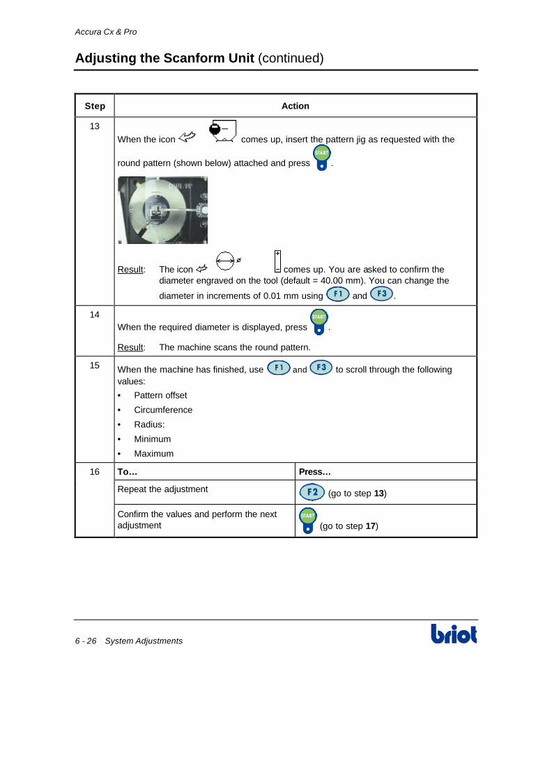
13
When the icon comes up, insert the pattern jig as requested with the
round pattern (shown below) attached and press .
Result: The icon comes up. You are asked to confirm the diameter engraved on the tool (default = 40.00 mm). You can change the
diameter in increments of 0.01 mm using and .
14 When the required diameter is displayed, press .
Result: The machine scans the round pattern.
15 When the machine has finished, use and to scroll through the following values:
• Pattern offset
• Circumference
• Radius:
• Minimum
• Maximum
16 To… Press…
Repeat the adjustment (go to step 13)
Confirm the values and perform the next adjustment (go to step 17)

Accura Cx & Pro
System Adjustments 6 - 27
Adjusting the Scanform Unit (continued)
Running the Adjustment Procedure (continued)
Step Action
17
When the icon comes up, insert the pattern jig as requested with the
rectangular pattern (shown below) attached and press .
Result: The machine scans the rectangular pattern.
18 When the machine has finished, use and to scroll through the following values:
• Pattern axis
• Circumference
• Pattern D
• Pattern Dy
19 To… Press…
Repeat the adjustment (go to step 17)
Save the adjustments and return to the Adjustment menu
Return to the adjustment menu without saving the parameters

Accura Cx & Pro
6 - 28 System Adjustments
Lens Feelers Adjustment
Procedure
Follow the steps below to adjust the scanning system.
Step Action Diagram
1 Go to the scanning screen. -
2 Press simultaneously the and keys.
Result: The following screen comes up.
Yes No
Lens feelers adjustment
3 Press the Yes key.
Result: The following screen comes up.
Valid Esc
Assemble tool n° 14 04 199
4 Put adjustment tool n° 14 04 199 on the lens adapter shaft (left side).
5 Press and hold the key to close lens
clamping.
-
6 Press the Valid key.
Result: The adjustment is automatically performing.
-

Accura Cx & Pro
System Adjustments 6 - 29
Lens Feelers Adjustment (continued)
Procedure (continued)
Step Action Diagram
7 When the adjustment is performed, remove the tool n° 14 04 199 and press on Valid.
-
8 Press the Fct7 key to save the adjustment.
Result: The scanning screen comes up.
Fct7
Note: This calibration influences the bevel tracking. A calibration performed poorly can induce a bad work quality of the edger.

7 System Cleaning


Accura Cx & Pro
System Cleaning 7 - 3
Cleaning the Edger
Introduction
In order for your new system to retain its new appearance and ensure proper mechanical operation, simple care must be taken on a routine basis:
• Clean the edger daily after use
• Follow the direction mentioned in this section
• Care your Briot after sales technician to arrange periodic maintenance.
Daily Cleaning
Basic daily cleaning consists of :
• Dust removal by using:
• Pure water or Briot Rex Net
• A soft sponge
• Mild soap or glass cleaner or
• A soft brush. Always wet edger surfaces with a spray bottle with water, to avoid scratching when cleaning.
• Carefully dust removal of the scanform™ feeler tip.
Caution
Do not use any type of spray hose to clean your system. Avoid any heavy splashing or spraying that may penetrate the system's scanning and keyboard/interface. This can cause electrical damage to the system.
Never use chemical solvents, agents or derivatives of such products as:
• Acetone
• Trichlorethylene
• Benzene
• Kerozene
• Lighter Fluid or
• Any product that claims "Do not use on plastic or painted surfaces" or that contains CHLORINE, AMMONIA, SODA.
These products directly or even by their simple vapors:
• Might alter the structure and appearance of your system
• Usage of any of these materials will void any guarantee or warranty of the whole unit or its components.
Never manipulate the lens feeler pliers located in the edging station.

8 Maintenance

Accura Cx & Pro
Maintenance 8 - 3
Scanform messages
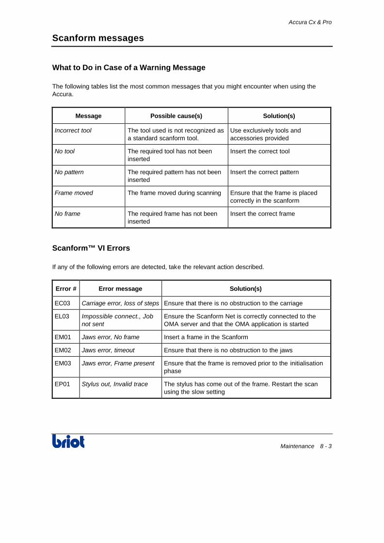
What to Do in Case of a Warning Message
The following tables list the most common messages that you might encounter when using the Accura.
Message Possible cause(s) Solution(s)
Incorrect tool The tool used is not recognized as a standard scanform tool.
Use exclusively tools and accessories provided
No tool The required tool has not been inserted
Insert the correct tool
No pattern The required pattern has not been inserted
Insert the correct pattern
Frame moved The frame moved during scanning Ensure that the frame is placed correctly in the scanform
No frame The required frame has not been inserted
Insert the correct frame
Scanform™ VI Errors
If any of the following errors are detected, take the relevant action described.
Error # Error message Solution(s)
EC03 Carriage error, loss of steps Ensure that there is no obstruction to the carriage
EL03 Impossible connect., Job not sent
Ensure the Scanform Net is correctly connected to the OMA server and that the OMA application is started
EM01 Jaws error, No frame Insert a frame in the Scanform
EM02 Jaws error, timeout Ensure that there is no obstruction to the jaws
EM03 Jaws error, Frame present Ensure that the frame is removed prior to the initialisation phase
EP01 Stylus out, Invalid trace The stylus has come out of the frame. Restart the scan using the slow setting

Accura Cx & Pro
8 - 4 Maintenance
Scanform messages (continued)
Scanform™ VI Errors (continued)
Error # Error message Solution(s)
EP02 Frame moved, Invalid trace Closing error - the point at which the scan began does not correspond to the point at which it finished (rho and Z). Restart the scan using the slow setting. This error is normally caused by the frame moving during the scan
EP04 Stylus error, Insufficient stroke
Ensure that there is no obstruction to the stylus horizontal movement
EP05 Insert. error, Insufficient stroke
The stylus cannot reach the end of its horizontal stroke. Ensure that there is no obstruction preventing the stylus from moving back and forth during the initialization step
EP07 Height error, insufficient stroke
The stylus cannot reach the end of its stroke. Ensure that there is no obstruction preventing the stylus from moving upwards
EP08 Stylus out, Scan pattern error
The tracer could not trace the pattern. Restart the scan using the slow setting
ER01 Turret, timeout Ensure that there is no obstruction to turret
ER03 Turret, Jamming: photocell The turret is jamming. Ensure there is no stopping point along its rotation movement
ET01 Rods error, timeout Ensure that there is no obstruction to the rods
ET03 Rods error, Insufficient stroke
Ensure that there is no obstruction to the rods and frame clips
EA01 Adjustment error The calibration failed. Do it again

Accura Cx & Pro
Maintenance 8 - 5
Edger messages
Message Types
The following table describes the messages of the operator dialogue.
Type Description Acquittal
Warning Allow to pay attention on an illogical procedure or a minor event.
By OK.
N° 000000000008 ΠΠ
+00.00
ORGANIQUE
* * * * * W A R N I N G * * * * * * * * * * W A R N I N G * * * * * O r i g i n : E d g i n g T y p e : R a d i u s < 1 0 m m
O K
Question Indicate that you must choose between two solutions.
By Yes or No.
N ° 0 0 0 0 0 0 0 0 0 0 0 8 ΠΠ
+00.00
ORGANIQUE
* * * * * W A R N I N G * * * * * * * * * * W A R N I N G * * * * * O r i g i n : E d g i n g
T y p e : R e - e d g e s a m e l e n s ? Y e s N o
• While the message is displayed, the operator dialogue is inhibited.
• The message area disappears from the screen when the message is acknowledged.

Accura Cx & Pro
8 - 6 Maintenance
Edger messages (continued)
Scanform™ origin
The following table shows the messages that can display during the scanform™ use.
N° Message Cause
01 05 Tracing aborted You pressed the key during scanning cycle for
example.
01 09 No Scanform Link problem with the scanform™.
01 10 Shape closure prob., continue?
The frame has possibly moved during tracing. The calculation algorithm can correct this problem but the lens edged may not match the frame shape ( size a little too large)
• Yes: correct the problem and carry on.
• No: stop the process and trace the frame again.
Layout origin
The following table shows the messages that can display in the layout mode.
N° Message Cause
02 03 Unknown job Call of one job number being neither the current job nor the previous job aid of the keypad.
Scanning origin
The following table shows the messages that can display in the scanning mode.
N° Message Cause
03 01 Memory full More than 300 jobs in memory (permanent or volatile jobs not edged).
03 04 Overwrite the present job? You start a scanning cycle of a job already scanned.
03 05 Edging previous job While you create the job n° 3 whereas the job n° 1 is in edging cycle.

Accura Cx & Pro
Maintenance 8 - 7
Edger messages (continued)
Scanning origin (continued)
N° Message Cause
03 06 Overwrite the job in memory? • The job number to save already exists in memory.
• If not, the job is saved under another number.
03 08 Edging present job You try to scan again the present job during the edging of this job.
03 09 Are you sure? If yes, the current job is deleted.
03 11 Incompatible edger config. Incompatibility problem between job parameters and edger setting.
Example: Job with Polycarbonate lenses on a machine not equipped with TP wheel.
Edging origin
The following table shows the messages that can display in the edging mode.
N° Message Cause
04 01 Retouch impossible A retouch is required while a lens has not been edged yet.
04 02 Lens feelers not in position One of the lens feelers was not in correct position before sensing the lens. Check there is no lens debris preventing a normal motion of the lens feelers.
04 04 Small adapters mounted? Frame shape requires the adapters Ø 19mm. Make sure they are mounted before going on.
04 05 Lens too small for shape Lens too small or too decentered in comparison with the shape.
04 06 Radius < 10 mm Shape too small. (Try to work in boxing mode.)
04 07 Re edge same lens? Lens edging from a job on the screen already edged.
04 08 Bevel too much at the back Top of the bevel more than 5 mm from the front face.

Accura Cx & Pro
8 - 8 Maintenance
Edger messages (continued)
Edging origin (continued)
N° Message Cause
04 09 Safety bvl: radius too small Radius too small for safety bevel.
04 10 Do you want to continue? This message appears when the edging time exceeded the limit of the machine (8 min). The operator has the choice to continue or stop the edging process.
04 11 Lens too thick for rimless Lens thickness higher than 10.4 mm.
04 12 Finishing impossible Finishing time upper than 3 min (carriage contact problem).
04 13 Groove. Lens too small One of the diameter of the lens is too small and the sockets may touch the safety-bevel/grooving wheel.
04 14 Impossible edge Problem on the main motor. Rotation speed too low or null.
05 02 Grooving wheel too small Grooving wheel worn out. The depth can not be reached.
05 03 Lens too thick to groove • Lens thickness upper than 9.55 mm between front face and grooving (lens safety-bevel/bush collision possible).
• Lens thickness upper than 9.60 mm between rear face and grooving (lens safety-bevel/wheel collision possible).
05 04 Groove. Lens too thin <1.5 mm Lens thickness is lower than 1.5 mm.
05 05 Grooving impossible Too much lens curve.
05 06 Bevel top out lens Continue?
During automatic bevel, the machine detects that the bevel may go out of the lens edge. Shall we finish the lens?
05 07 Lens feelers : Aberrant spots Irregular points detected during lens tracing.
Example: For a 1/2 eye lens, the adhesive has not been cut before blocking.

Accura Cx & Pro
Maintenance 8 - 9
Edger messages (continued)
Edging origin (continued)
N° Message Cause
05 08 Job not aesthetical The bevel or groove calculated by the expert program might result a non aesthetic glazing. The operator can modify its base curve and/or position upon his criteria.
05 09 Improper lens to retouch The inserted lens doesn’t match with the lens to retouch – Check lens side (R/L) or that the lens is not an uncut lens.
05 10 Finish. dressing recommended The Accura recommends to dress the finishing (bevel) wheel (more than 800 lenses edged since the last dressing).
Acknowledge the message and proceed to the finishing wheel dressing.
05 12 Small flat adapters mounted? Frame shape requires the adapters Ø 17mm. Make sure they are mounted before going on.
05 13 Thin lens to groove, continue? Part of the lens has a thickness between 1mm and 1.4mm and the groove may be fragile.
05 14 Large adapters mounted? Frame shape requires the large adapters. Make sure they are mounted before going on.
Extension circuit board origin
The following table shows the message that can display because of the extension circuit board.
Type Message Cause
06 01 Extension board failure Communication problem between main circuit board and memory extension circuit board.
06 02 <Server message> There is no connection with the OMA server.
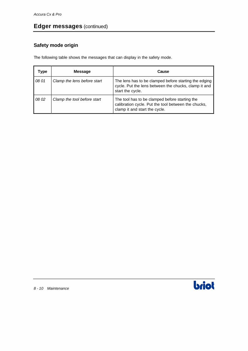
Accura Cx & Pro
8 - 10 Maintenance
Edger messages (continued)
Safety mode origin
The following table shows the messages that can display in the safety mode.
Type Message Cause
08 01 Clamp the lens before start The lens has to be clamped before starting the edging cycle. Put the lens between the chucks, clamp it and start the cycle.
08 02 Clamp the tool before start The tool has to be clamped before starting the calibration cycle. Put the tool between the chucks, clamp it and start the cycle.

Appendix A Installing a Recirculating System

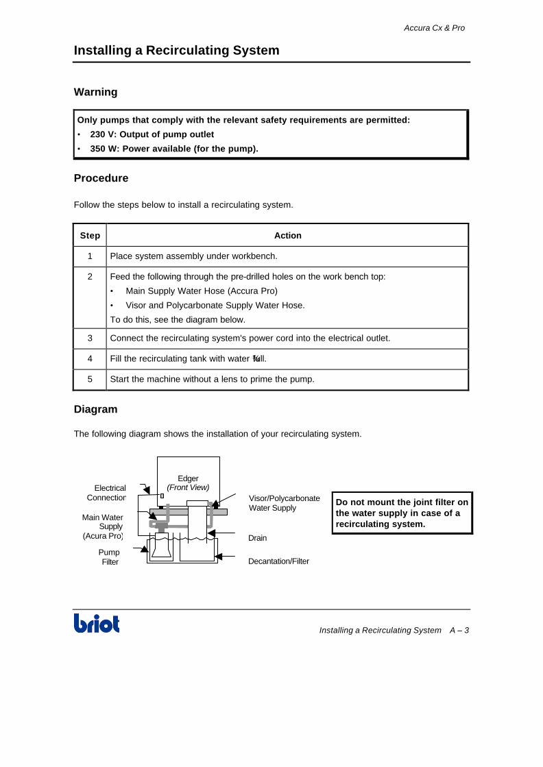
Accura Cx & Pro
Installing a Recirculating System A – 3
Installing a Recirculating System
Warning
Only pumps that comply with the relevant safety requirements are permitted:
• 230 V: Output of pump outlet
• 350 W: Power available (for the pump).
Procedure
Follow the steps below to install a recirculating system.
Step Action
1 Place system assembly under workbench.
2 Feed the following through the pre-drilled holes on the work bench top:
• Main Supply Water Hose (Accura Pro)
• Visor and Polycarbonate Supply Water Hose.
To do this, see the diagram below.
3 Connect the recirculating system's power cord into the electrical outlet.
4 Fill the recirculating tank with water ¾ full.
5 Start the machine without a lens to prime the pump.
Diagram
The following diagram shows the installation of your recirculating system.
Do not mount the joint filter on the water supply in case of a recirculating system.
Edger(Front View)Electrical
Connection
PumpFilter
Visor/PolycarbonateWater Supply
Drain
Decantation/Filter
Main WaterSupply
(Acura Pro)
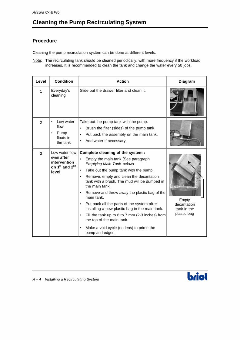
Accura Cx & Pro
A – 4 Installing a Recirculating System
Cleaning the Pump Recirculating System
Procedure
Cleaning the pump recirculation system can be done at different levels.
Note: The recirculating tank should be cleaned periodically, with more frequency if the workload increases. It is recommended to clean the tank and change the water every 50 jobs.
Level Condition Action Diagram
1 Everyday's cleaning
Slide out the drawer filter and clean it.
2 • Low water flow
• Pump floats in the tank
Take out the pump tank with the pump.
• Brush the filter (sides) of the pump tank
• Put back the assembly on the main tank.
• Add water if necessary.
3 Low water flow even after intervention on 1st and 2nd level
Complete cleaning of the system :
• Empty the main tank (See paragraph Emptying Main Tank below).
• Take out the pump tank with the pump.
• Remove, empty and clean the decantation tank with a brush. The mud will be dumped in the main tank.
• Remove and throw away the plastic bag of the main tank.
• Put back all the parts of the system after installing a new plastic bag in the main tank.
• Fill the tank up to 6 to 7 mm (2-3 inches) from the top of the main tank.
• Make a void cycle (no lens) to prime the pump and edger.
Emptydecantationtank in theplastic bag
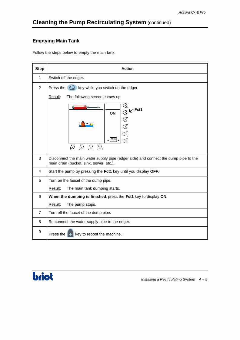
Accura Cx & Pro
Installing a Recirculating System A – 5
Cleaning the Pump Recirculating System (continued)
Emptying Main Tank
Follow the steps below to empty the main tank.
Step Action
1 Switch off the edger.
2 Press the key while you switch on the edger.
Result: The following screen comes up.
ONFct1
3 Disconnect the main water supply pipe (edger side) and connect the dump pipe to the main drain (bucket, sink, sewer, etc.).
4 Start the pump by pressing the Fct1 key until you display OFF.
5 Turn on the faucet of the dump pipe.
Result: The main tank dumping starts.
6 When the dumping is finished, press the Fct1 key to display ON.
Result: The pump stops.
7 Turn off the faucet of the dump pipe.
8 Re-connect the water supply pipe to the edger.
9 Press the key to reboot the machine.

Appendix B Functioning with Memory Board & Network Connection


Accura Cx & Pro
Functioning with Memory Board & Network Connection B – 3
Bar Code Reader
Connection to the edger
Connect the bar code reader cable on the back connector (9-pin connector).
I
O
FRANCE: Conforme aux réglements du ministère du travail à laConstructeHerstelManufactur
BRIOTF27 - PONT DEAnnée deJahYear 1996
ImmatriculaSeriennummSerial
N°22034
Q 51
230 V 1~ 50 Hz 1000 W 4 A
ServiBetriebsaRunning
ContinD BContinuou
T/min. aU/minLeerlaufRPM
2800ProtectiSchutza IP 20
Made in
ATTENTION : Débranchez la prise
de courant avant toute interventionsur la machine
WARNING : Disconnect supply beforeremoving covers
WARNUNG : Bitte ziehen sieunbedingt den stecker aud der
steckdose bevor sie die maschine off CE
Using
When you are in the scanning mode, move closer the bar code reader over the bar code label of the tray or of the frame for example.
Result:
• A new job is created (if no number in the memory) wearing the number referenced by the bar code reader.
Or
• The job number, the shape and/or the selected job parameters come up on the screen (if already present in memory).

Accura Cx & Pro
B – 4 Functioning with Memory Board & Network Connection
Memory Extension Circuit Board
Creation and Saving a Job
Follow the steps below to create and save a job.
Step Action
1 Press one or several times the Fct0 to access to scanning mode.
N ° 0 0 0 0 0 0 0 0 0 0 0 8
METAL
+70.38
F c t 8F c t 6
F c t 0
F c t 9
2 Enter a job number aid of the keyboard or the bar code reader.
3 Press the Fct6 key to display job origin (in this case the scanform™ ).
4 Press the Fct8 key to indicate to the machine that you wish to save this new job.
5 Press the Fct9 key to select the memory zone where the job will have to locate.
Setting Function
Save the job in non protected memory: the job is staying in memory:
• As long as there is room left in memory and
• As long as the job has not been edged.
Save the job in protected memory: the job is staying always in memory (except if you wish to delete it).
6 Enter the scanning parameters and scan your job. To do this, see Chapter 3 Scanning.
7 Access to layout/blocking screen and enter data concerning this job (distance, high…). To do this, see Chapter 4 Layout/Blocking.
8 Access to edging screen and enter data concerning this job (lens type, bevel, safety-bevel…). To do this, see Chapter 5 Edging.

Accura Cx & Pro
Functioning with Memory Board & Network Connection B – 5
Memory Extension Circuit Board (continued)
Creation and Saving a Job (continued)
Step Action
9 Press the Fct0 key to access again to scanning screen.
10 Create a new job, aid of the keyboard, the bar code reader or the key.
Result:
If the job number…
Then…
Is not in memory The job is now saved on specified number.
Is in memory The following message comes up:
N ° 0 0 0 0 0 0 0 0 0 0 0 8
METAL
+70.38
*****WARNING***** *****WARNING***** Origin : Tracing Type : Overwrite the present job ? Yes No
If you… Then…
Press Yes • The job that existed before under the same number is overwritten.
• The job just created is now in memory.
Press No • The following screen is displaying with the job number on which the new job will be saved.
N ° 0 0 0 0 0 0 0 0 0 0 0 8
METAL
+70.38 *****WARNING***** *****WARNING***** Origin : Tracing Type : Job # 00007Ok
Accura Cx & Pro
B – 6 Functioning with Memory Board & Network Connection
Memory Extension Circuit Board (continued)
Advises
• Note properly the job number you just created. It equivalents to the new job number for a further call.
• If you wish to save the last job of the day, do not forget to press the key in
scanning mode before switching off the machine.
• If you use the tray number as job number, it is advisable to answer Yes to the message Overwrite the present job?. Otherwise, the job will be saved under another number.

Accura Cx & Pro
Functioning with Memory Board & Network Connection B – 7
Memory Extension Circuit Board (continued)
Call a Job in Memory
Follow the steps below to call a job in memory.
Step Action
1 Press one or several times the Fct0 key to access to scanning mode.
N ° 0 0 0 0 0 0 0 0 0 0 0 8
METAL
+70.38
Fct8Fct6
Fct0
2 Enter the job number to recall, aid of the keyboard or the bar code reader.
3 Press the Fct6 key to display the job origin (in this case the memory ).
4 If necessary, press the Fct8 key to save the job if you think you will modify it.
5 Press the key to call the job.
Result: The saved job is displaying.
6 Access to layout/blocking and edging screens to block the job lenses and to edge them. To do this, see Chapter 4 Layout/Blocking and Chapter 5 Edging.
7 If you selected saving option , repeat steps 9 and 10 of procedure Creation and Saving a Job formerly.
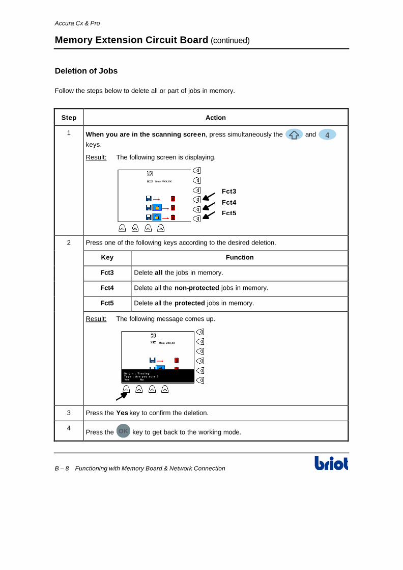
Accura Cx & Pro
B – 8 Functioning with Memory Board & Network Connection
Memory Extension Circuit Board (continued)
Deletion of Jobs
Follow the steps below to delete all or part of jobs in memory.
Step Action
1 When you are in the scanning screen, press simultaneously the and
keys.
Result: The following screen is displaying.
Mem VXX.XX
Fct3
Fct4
Fct5
2 Press one of the following keys according to the desired deletion.
Key Function
Fct3 Delete all the jobs in memory.
Fct4 Delete all the non-protected jobs in memory.
Fct5 Delete all the protected jobs in memory.
Result: The following message comes up.
Mem VXX.XX
* * * * * W A R N I N G * * * * * * * * * * W A R N I N G * * * * * O r i g i n : T r a c i n g T y p e : A r e y o u s u r e ? Yes No N o n
3 Press the Yes key to confirm the deletion.
4 Press the key to get back to the working mode.

Accura Cx & Pro
Functioning with Memory Board & Network Connection B – 9
Communication Extension Circuit Board
Creation and Saving a Job
Follow the steps below to create and save a job.
Step Action
1 Press one or several times the Fct0 to access to scanning mode.
N ° 0 0 0 0 0 0 0 0 0 0 0 8
METAL
+70.38
F c t 8F c t 6
F c t 0
2 Enter a job number aid of the keyboard or the bar code reader.
3 Press the Fct6 key to display job origin (in this case the scanform™ ).
4 Press the Fct8 key to indicate to the machine that you wish to save this new job.
5 Select the server memory zone where the job will have to locate.
6 Enter the scanning parameters and scan your job. To do this, see Chapter 3 Scanning.
7 Access to layout/blocking screen and enter data concerning this job (distance, high…). To do this, see Chapter 4 Layout/Blocking.
8 Access to edging screen and enter data concerning this job (lens type, bevel, safety-bevel…). To do this, see Chapter 5 Edging.
9 Press the Fct0 key to access again to scanning screen.

Accura Cx & Pro
B – 10 Functioning with Memory Board & Network Connection
Communication Extension Circuit Board (continued)
Creation and Saving a Job (continued)
Step Action
10 Create a new job, aid of the keyboard, the bar code reader or the key.
Result:
If the job number… Then…
Is not in server memory
The job is now saved on specified number.
Is in server memory The following message is displaying:
N ° 0 0 0 0 0 0 0 0 0 0 0 8
METAL
+70.38 *****WARNING***** *****WARNING***** Origin : Tracing Type : Overwrite the present job ? Yes No
If you… Then…
Press YES • The job that existed before under the same number is overwritten.
• The job just created is now in server memory.
Press NO • The following screen is displaying with the job number on which the new job will be saved.
N ° 0 0 0 0 0 0 0 0 0 0 0 8
METAL
+70.38
*****WARNING***** *****WARNING***** Or igin : Tracing Type : Job # 00007
Ok

Accura Cx & Pro
Functioning with Memory Board & Network Connection B – 11
Communication Extension Circuit Board (continued)
Advises
• Note properly the job number you just created. It equivalents to the new job number for a further call.
• If you wish to save the last job of the day, do not forget to press the key in
scanning mode before switching off the machine.
• If you use the tray number as job number, it is advisable to answer Yes to the message Overwrite the present job?. Otherwise, the job will be saved under another number.

Accura Cx & Pro
B – 12 Functioning with Memory Board & Network Connection
Communication Extension Circuit Board (continued)
Call a Job in Memory
Follow the steps below to call a job in the memory of the server.
Step Action
1 Press one or several times the Fct0 key to access to scanning mode.
N ° 0 0 0 0 0 0 0 0 0 0 0 8
METAL
+70.38
F c t 8F c t 6
F c t 0
2 Enter the job number to recall, aid of the keyboard or the bar code reader.
3 Press the Fct6 key to display the job origin (in this case the server ).
4 If necessary, press the Fct8 key to save the job if you think you will modify it.
5 Press the key to call the job.
Result: The saved job comes up.
6 Access to layout/blocking and edging screens to block the job lenses and to edge them. To do this, see Chapter 4 Layout/Blocking and Chapter 5 Edging.
7 If you selected saving option , repeat steps 9 and 10 of procedure Creation and
Saving a Job formerly.

Appendix C Specifications

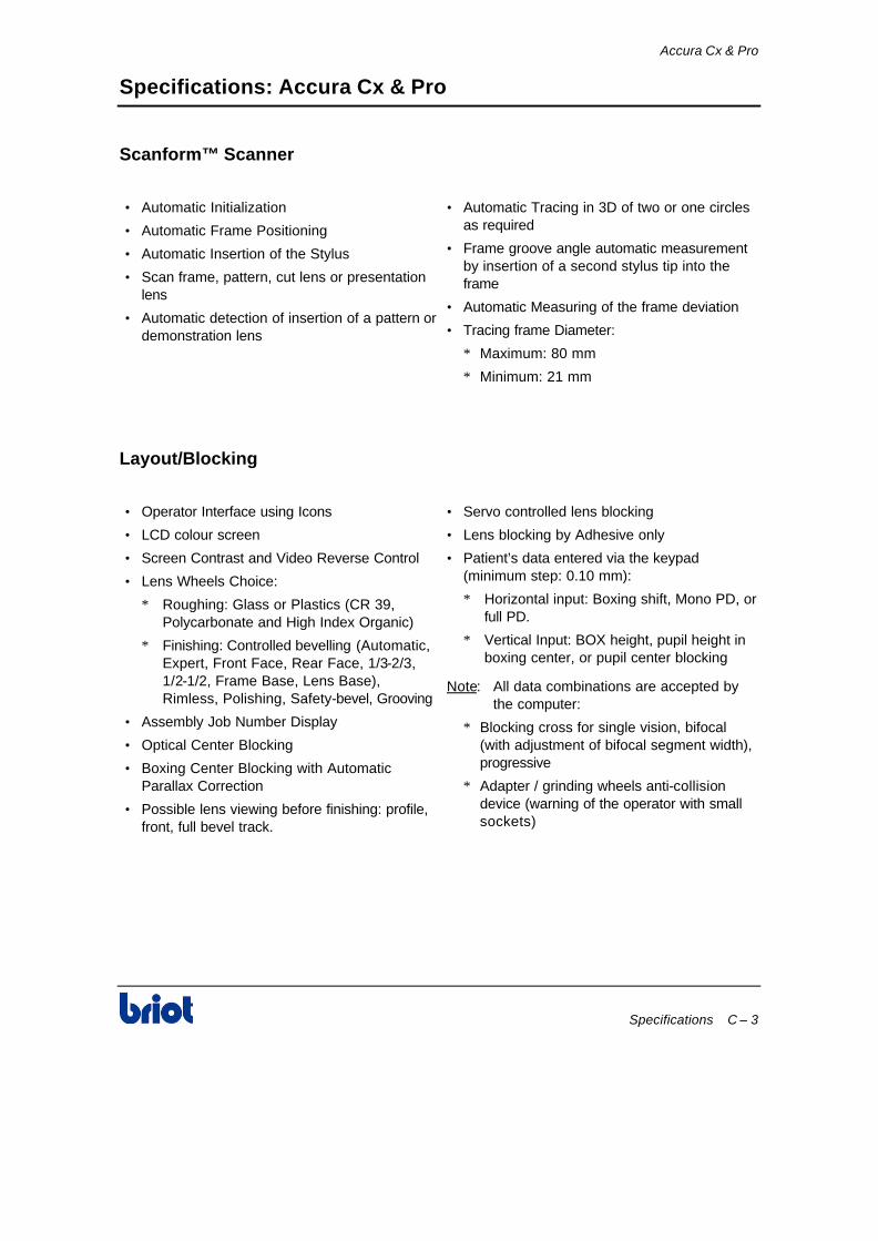
Accura Cx & Pro
Specifications C – 3
Specifications: Accura Cx & Pro
Scanform™ Scanner
• Automatic Initialization
• Automatic Frame Positioning
• Automatic Insertion of the Stylus
• Scan frame, pattern, cut lens or presentation lens
• Automatic detection of insertion of a pattern or demonstration lens
• Automatic Tracing in 3D of two or one circles as required
• Frame groove angle automatic measurement by insertion of a second stylus tip into the frame
• Automatic Measuring of the frame deviation
• Tracing frame Diameter:
∗ Maximum: 80 mm
∗ Minimum: 21 mm
Layout/Blocking
• Operator Interface using Icons
• LCD colour screen
• Screen Contrast and Video Reverse Control
• Lens Wheels Choice:
∗ Roughing: Glass or Plastics (CR 39, Polycarbonate and High Index Organic)
∗ Finishing: Controlled bevelling (Automatic, Expert, Front Face, Rear Face, 1/3-2/3, 1/2-1/2, Frame Base, Lens Base), Rimless, Polishing, Safety-bevel, Grooving
• Assembly Job Number Display
• Optical Center Blocking
• Boxing Center Blocking with Automatic Parallax Correction
• Possible lens viewing before finishing: profile, front, full bevel track.
• Servo controlled lens blocking
• Lens blocking by Adhesive only
• Patient’s data entered via the keypad (minimum step: 0.10 mm):
∗ Horizontal input: Boxing shift, Mono PD, or full PD.
∗ Vertical Input: BOX height, pupil height in boxing center, or pupil center blocking
Note: All data combinations are accepted by the computer:
∗ Blocking cross for single vision, bifocal (with adjustment of bifocal segment width), progressive
∗ Adapter / grinding wheels anti-collision device (warning of the operator with small sockets)
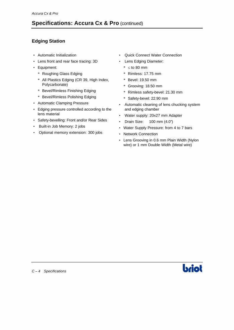
Accura Cx & Pro
C – 4 Specifications
Specifications: Accura Cx & Pro (continued)
Edging Station
• Automatic Initialization
• Lens front and rear face tracing: 3D
• Equipment:
∗ Roughing Glass Edging
∗ All Plastics Edging (CR 39, High Index, Polycarbonate)
∗ Bevel/Rimless Finishing Edging
∗ Bevel/Rimless Polishing Edging
• Automatic Clamping Pressure
• Edging pressure controlled according to the lens material
• Safety-bevelling: Front and/or Rear Sides
• Built-in Job Memory: 2 jobs
• Optional memory extension: 300 jobs
• Quick Connect Water Connection
• Lens Edging Diameter:
∗ ≤ to 80 mm
∗ Rimless: 17.75 mm
∗ Bevel: 19.50 mm
∗ Grooving: 18.50 mm
∗ Rimless safety-bevel: 21.30 mm
∗ Safety-bevel: 22.90 mm
• Automatic cleaning of lens chucking system and edging chamber
• Water supply: 20x27 mm Adapter
• Drain Size: ∅ 100 mm (4.0”)
• Water Supply Pressure: from 4 to 7 bars
• Network Connection
• Lens Grooving in 0.6 mm Plain Width (Nylon wire) or 1 mm Double Width (Metal wire)

Accura Cx & Pro
Specifications C – 5
Specifications: Accura Cx
Specifications
• Dimensions:
∗ Width: 26” (660 mm)
∗ Depth: 24” (620 mm)
∗ Height (visor close): 17” (430 mm)
∗ Height (visor open): 20.5” (520 mm)
• Weight: 165 lb. (75 kg)
• Power Supply: 230 V/50 Hz, 115 V/60 Hz
• Power Consumption: 1000 W
• Sound Level: 72 dB
• Pollution Degree: 2
• Installation Category: II
• Ambient Temperature: 13° C to 35° C
• Relative Humidity: 10% to 80%
• Maximum Water Pressure: 7 Bar
• Maximum Pump Pressure (with Pump): 7 Bar
• Output of Pump Outlet:
∗ 115 V/230 V: Supply Voltage
∗ 350 W: Power available (for the pump)
• Fuses to be used for 230 V edger:
∗ F1 & F2 : 10 AT Little Fuse 32606
∗ F3 : 3,15 AT Little Fuse 2183-15
∗ F4 & F5 : 2 AT Little Fuse 218002
∗ F6 : 5 AT Ferraz 250V 55T 5x20
• Fuses to be used for 115 V edger:
∗ F1 & F2 : 25 AT Ferraz 125 V SA 6,3x32 Ref. T84 427
∗ F3 : 5 AT Ferraz 250 V 5ST 5x20
∗ F4 & F5 : 5 AT Ferraz 250V 55T 5x20
∗ F6 : 5 AT Ferraz 250V 55T 5x20
• EC Standards for 230V EC Version:
∗ In compliance with Safety EC Requirement Di 89/392/CEE
♦ EN 60204
♦ EN 60950
♦ EN 60742
∗ In compliance with EMC EC Requirement Di 89/336/CEE
♦ EN 55022 "Class B"
♦ EN 61000 - 4 - 2
♦ EN 61000 - 4 - 3
♦ EN 61000 - 4 - 4
• UL Standards for 115V US Version:
♦ UL 3101
♦ FCC part 15, subpart J. Class A

Accura Cx & Pro
C – 6 Specifications
Specifications: Accura Pro
Specifications
• Dimensions:
∗ Width: 26” (660 mm)
∗ Depth: 24” (620 mm)
∗ Height (visor close): 17” (430 mm)
∗ Height (visor open): 20.5” (520 mm)
• Weight: 165 lb. (75 kg)
• Power Supply: 230 V/50 Hz, 60 Hz
• Power Consumption: 500 W
• Sound Level: 72 dB
• Pollution Degree: 2
• Installation Category: II
• Ambient Temperature: 13° C to 35° C
• Relative Humidity: 10% to 80%
• Maximum Water Pressure: 7 Bar
• Maximum Pump Pressure (with Pump): 7 Bar
• Output of Pump Outlet:
∗ 230 V: Supply Voltage
∗ 350 W: Power available (for the pump)
• Fuses to be used for 230 V edger:
∗ F1 & F2: 10 AT Little Fuse 32606
∗ F3: 3,15 AT Little Fuse 2183-15
∗ F4 & F5: 2 AT Little Fuse 218002
∗ F6: 5 AT Ferraz 250V 55T 5x20
∗ F7: 2 AT
• EC Standards for 230V EC Version:
∗ In compliance with Safety EC Requirement Di 89/392/CEE
♦ EN 60204
♦ EN 60950
♦ EN 60742
∗ In compliance with EMC EC Requirement Di 89/336/CEE
♦ EN 55022 "Class A"
♦ EN 61000 - 4 - 2
♦ EN 61000 - 4 - 3
♦ EN 61000 - 4 - 4
♦ UL Standards for 115V US Version: UL 3101