Dean vortices-induced enhancement of mass transfer …gelfgat/documents/Gelfgat_Ref24.pdf · Dean...
18
Dean vortices-induced enhancement of mass transfer through an interface separating two immiscible liquids A. Yu. Gelfgat Department of Fluid Mechanics and Heat Transfer, Faculty of Engineering, Tel-Aviv University, Ramat Aviv 69978, Israel A. L. Yarin and P. Z. Bar-Yoseph Faculty of Mechanical Engineering, Technion – Israel Institute of Technology, Haifa, 32000, Israel ~Received 9 May 2002; accepted 4 November 2002; published 7 January 2003! Two-fluid Dean vortex flow in a coiled pipe with vanishing torsion, and its effect on the mass transfer through the liquid–liquid interface of two immiscible fluids are studied numerically. The liquids are stratified by gravity, with the denser one occupying the lower part of the pipe. The Navier–Stokes equations in both fluid layers are solved numerically by the finite volume method. The results reveal a detailed structure of the transverse flow ~the Dean vortices! in coiled pipes with the dimensionless curvature 0.1. Both cocurrent and countercurrent axial flows in the fluid layers are considered. Using the flow fields predicted, the mass transfer equation is solved. It is shown that the mass transfer of a passive scalar ~say, a protein with the Schmidt number of the order of 10 3 ) through the interface can be significantly enhanced by the Dean vortices, so that the mass transfer rate can be increased by three to four times. This makes the Dean vortex flow an effective tool for mass transfer enhancement at the liquid–liquid interface. It is shown that the Dean flow provides a stronger mixing than the Taylor–Couette flow. It is also shown that there exists an optimal axial flow rate in terms of this enhancement. The optimal flow corresponds to the value of the Dean number of about 180. In the countercurrent flow case the Dean vortices can split, which has a negative effect on the mass transfer enhancement. Both the cocurrent and countercurrent axial flows yield a similar enhancement effect on the interfacial mass transfer rate. The problem is related to the search for novel bioseparator devices. © 2003 American Institute of Physics. @DOI: 10.1063/1.1532732# I. INTRODUCTION In the present study, the effect of a two-fluid Dean vor- tical flow on mass transfer through an interface separating two immiscible liquids is examined. The study is motivated by the problem of extraction of admixtures having extremely low diffusion coefficients, e.g., proteins. Since purely diffu- sional mass transfer of such admixtures is too slow and has to be enhanced, mixing by vortical flows is called for. 1 In such flows the vortices inside each fluid transport the admix- ture toward the interface, which yields steeper concentration gradients there. As a result, the mass fluxes through the in- terface increase and the mass transfer intensifies, even though the diffusion coefficient remains small. The first ex- perimental attempt in this direction was made in Ref. 2, with two-fluid Taylor–Couette vortical flow used in a specially designed bioseparator/bioreactor. This configuration was fur- ther studied theoretically and numerically in Ref. 3, where the effect of the Taylor vortices and of the axial throughflow on the mass transfer rates was investigated. Practical appli- cation of the two-fluid Taylor–Couette apparatus was found to be problematic because the contact of the rapidly rotating cylindrical boundaries ~e.g., in the experiments 2 the rotation rate exceeded 10 rev/s! with the stationary closed ends leads to instability of the liquid–liquid interface. This instability was also observed numerically by the present group. It was compared to the experimental results obtained using the de- vice of Refs. 1 and 2, and the results will be published in a separate paper. Search for configurations in which the vorti- cal flow can be generated without motion of the boundaries, and which can be implemented in novel bioseparators/ bioreactors, led to study of stationary dc streaming generated in emulsions, 4 thin channels with capillary waves, 5 and of natural-convection flow in two-layer horizontal annuli. The Dean vortices arising in coiled pipe single-liquid flows are known as an effective means for heat and mass transfer enhancement ~see Refs. 6–11 and references therein!. In particular, Refs. 6 and 7 were motivated by the need to prevent buildup of retained solute concentration near a membrane in a reverse osmosis system. In these works it was shown that the concentration buildup, known as concen- tration polarization, can be significantly reduced if solutions are supplied through curved channels, where the Dean vorti- ces arise. The Dean vortices effectively mix the retained sol- ute and this results in depolarization and a significant in- crease in the transmembrane flux. In Refs. 6 and 7, as well as in the previous works of that group, direct numerical simu- lation was used to calculate the velocity fields in curved channels and pipes with single fluid flowing under different conditions ~different Reynolds numbers, channel curvature, etc.!. Comparison with the experimental data obtained by means of magnetic resonance flow imaging showed that the numerical results are capable of reproducing the details of the secondary flows ~the Dean vortices! rather accurately in- PHYSICS OF FLUIDS VOLUME 15, NUMBER 2 FEBRUARY 2003 330 1070-6631/2003/15(2)/330/18/$20.00 © 2003 American Institute of Physics Downloaded 17 Jan 2003 to 132.68.1.29. Redistribution subject to AIP license or copyright, see http://ojps.aip.org/phf/phfcr.jsp
-
Upload
phungkhuong -
Category
Documents
-
view
218 -
download
0
Transcript of Dean vortices-induced enhancement of mass transfer …gelfgat/documents/Gelfgat_Ref24.pdf · Dean...
PHYSICS OF FLUIDS VOLUME 15, NUMBER 2 FEBRUARY 2003
Dean vortices-induced enhancement of mass transfer through an interfaceseparating two immiscible liquids
A. Yu. GelfgatDepartment of Fluid Mechanics and Heat Transfer, Faculty of Engineering, Tel-Aviv University,Ramat Aviv 69978, Israel
A. L. Yarin and P. Z. Bar-YosephFaculty of Mechanical Engineering, Technion–Israel Institute of Technology, Haifa, 32000, Israel
~Received 9 May 2002; accepted 4 November 2002; published 7 January 2003!
Two-fluid Dean vortex flow in a coiled pipe with vanishing torsion, and its effect on the masstransfer through the liquid–liquid interface of two immiscible fluids are studied numerically. Theliquids are stratified by gravity, with the denser one occupying the lower part of the pipe. TheNavier–Stokes equations in both fluid layers are solved numerically by the finite volume method.The results reveal a detailed structure of the transverse flow~the Dean vortices! in coiled pipes withthe dimensionless curvature 0.1. Both cocurrent and countercurrent axial flows in the fluid layers areconsidered. Using the flow fields predicted, the mass transfer equation is solved. It is shown that themass transfer of a passive scalar~say, a protein with the Schmidt number of the order of 103)through the interface can be significantly enhanced by the Dean vortices, so that the mass transferrate can be increased by three to four times. This makes the Dean vortex flow an effective tool formass transfer enhancement at the liquid–liquid interface. It is shown that the Dean flow provides astronger mixing than the Taylor–Couette flow. It is also shown that there exists an optimal axial flowrate in terms of this enhancement. The optimal flow corresponds to the value of the Dean numberof about 180. In the countercurrent flow case the Dean vortices can split, which has a negative effecton the mass transfer enhancement. Both the cocurrent and countercurrent axial flows yield a similarenhancement effect on the interfacial mass transfer rate. The problem is related to the search fornovel bioseparator devices. ©2003 American Institute of Physics.@DOI: 10.1063/1.1532732#
ortinedelu-h
ixtio
ivxithllyfurew
ppntin
ds
wad
arti-
ies,rs/ted
idass
esheearks iten-nsorti-ol-in-ll asu-edntre,bytheof
I. INTRODUCTION
In the present study, the effect of a two-fluid Dean vtical flow on mass transfer through an interface separatwo immiscible liquids is examined. The study is motivatby the problem of extraction of admixtures having extremlow diffusion coefficients, e.g., proteins. Since purely diffsional mass transfer of such admixtures is too slow andto be enhanced, mixing by vortical flows is called for.1 Insuch flows the vortices inside each fluid transport the admture toward the interface, which yields steeper concentragradients there. As a result, the mass fluxes through theterface increase and the mass transfer intensifies, ethough the diffusion coefficient remains small. The first eperimental attempt in this direction was made in Ref. 2, wtwo-fluid Taylor–Couette vortical flow used in a speciadesigned bioseparator/bioreactor. This configuration wasther studied theoretically and numerically in Ref. 3, whethe effect of the Taylor vortices and of the axial throughfloon the mass transfer rates was investigated. Practical acation of the two-fluid Taylor–Couette apparatus was fouto be problematic because the contact of the rapidly rotacylindrical boundaries~e.g., in the experiments2 the rotationrate exceeded 10 rev/s! with the stationary closed ends leato instability of the liquid–liquid interface. This instabilitywas also observed numerically by the present group. Itcompared to the experimental results obtained using the
3301070-6631/2003/15(2)/330/18/$20.00
Downloaded 17 Jan 2003 to 132.68.1.29. Redistribution subject to AIP
-g
y
as
-nn-en-
r-
li-dg
se-
vice of Refs. 1 and 2, and the results will be published inseparate paper. Search for configurations in which the vocal flow can be generated without motion of the boundarand which can be implemented in novel bioseparatobioreactors, led to study of stationary dc streaming generain emulsions,4 thin channels with capillary waves,5 and ofnatural-convection flow in two-layer horizontal annuli.
The Dean vortices arising in coiled pipe single-liquflows are known as an effective means for heat and mtransfer enhancement~see Refs. 6–11 and referenctherein!. In particular, Refs. 6 and 7 were motivated by tneed to prevent buildup of retained solute concentration na membrane in a reverse osmosis system. In these worwas shown that the concentration buildup, known as conctration polarization, can be significantly reduced if solutioare supplied through curved channels, where the Dean vces arise. The Dean vortices effectively mix the retained sute and this results in depolarization and a significantcrease in the transmembrane flux. In Refs. 6 and 7, as wein the previous works of that group, direct numerical simlation was used to calculate the velocity fields in curvchannels and pipes with single fluid flowing under differeconditions~different Reynolds numbers, channel curvatuetc.!. Comparison with the experimental data obtainedmeans of magnetic resonance flow imaging showed thatnumerical results are capable of reproducing the detailsthe secondary flows~the Dean vortices! rather accurately in-
© 2003 American Institute of Physics
license or copyright, see http://ojps.aip.org/phf/phfcr.jsp
331Phys. Fluids, Vol. 15, No. 2, February 2003 Dean vortices-induced enhancement
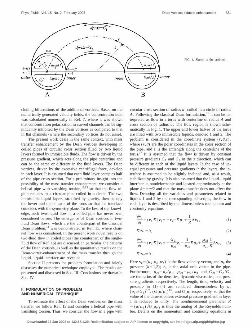
FIG. 1. Sketch of the problem.
thelwsihaeas
ideaalohaher
oy
acwewcano
-nstht
flysn
asithith
-use
ofent
n-e in-ult,idthethe
toinand
.
res-nd
yer
-in
cluding bifurcations of the additional vortices. Based onnumerically generated velocity fields, the concentration fiwas calculated numerically in Ref. 7, where it was shothat concentration polarization in curved channels can benificantly inhibited by the Dean vortices as compared to tin flat channels~where the secondary vortices do not aris!.
The present work deals in the same context, with mtransfer enhancement by the Dean vortices developingcoiled pipes of circular cross section filled by two liqulayers formed by immiscible fluids. The flow is driven by thpressure gradient, which acts along the pipe centerlinecan be the same or different in the fluid layers. The Devortices, driven by the excessive centrifugal force, devein each layer. It is assumed that each fluid layer occupiesof the pipe cross section. For a preliminary insight into tpossibility of the mass transfer enhancement, we considhelical pipe with vanishing torsion,12,13 so that the flow re-gion reduces to a circular pipe coiled in a circle. The twimmiscible liquid layers, stratified by gravity, then occupthe lower and upper parts of the torus so that the interfcoincides with the symmetry plane. To the best of our knoedge, such two-liquid flow in a coiled pipe has never beconsidered before. The emergence of Dean vortices in tfluid Dean flows, which are the counterpart of the classiDean problem,14 was demonstrated in Ref. 15, where chanel flow was considered. In the present work novel resultstwo-fluid flow in coiled pipes~the counterpart of the singlefluid flow of Ref. 16! are discussed. In particular, the patterof the Dean vortices, as well as the quantitative results onDean-vortex-enhancement of the mass transfer throughliquid–liquid interface are revealed.
Section II presents the problem formulation and briediscusses the numerical technique employed. The resultpresented and discussed in Sec. III. Conclusions are drawSec. IV.
II. FORMULATION OF PROBLEMAND NUMERICAL TECHNIQUE
To estimate the effect of the Dean vortices on the mtransfer we follow Ref. 13 and consider a helical pipe wvanishing torsion. Thus, we consider the flow in a pipe w
Downloaded 17 Jan 2003 to 132.68.1.29. Redistribution subject to AIP
edng-t
sin
ndnplf
ea
el-no-l
-n
ehe
arein
s
circular cross section of radiusa, coiled in a circle of radiusA. Following the classical Dean formulation,16 it can be in-terpreted as flow in a torus with centerline of radiusA andcross section of radiusa. The flow region is shown schematically in Fig. 1. The upper and lower halves of the torare filled with two immiscible liquids, denoted 1 and 2. Thproblem is considered in the coordinate system (r ,u,s),where (r ,u) are the polar coordinates in the cross sectionthe pipe, ands is the arclength along the centerline of thtorus.17 It is assumed that the flow is driven by constapressure gradientsG1 and G2 in the s direction, which canbe different in each of the liquid layers. In the case of uequal pressures and pressure gradients in the layers, thterface is assumed to be slightly inclined and, as a resstabilized by gravity. It is also assumed that the liquid–liquinterface is nondeformable and located approximately atplaneu56p/2 and that the mass transfer does not affectflow. Denoting all the variables and parameters relatedliquids 1 and 2 by the corresponding subscripts, the floweach layer is described by the dimensionless momentumcontinuity equations
]v1
]t1~v1"¹!v152es2¹p11
1
RDv1 , ~1!
¹"v150, ~2!
]v2
]t1~v2"¹!v252
G21
r21es2
1
r21¹p21
m21
r21
1
RDv2 , ~3!
¹"v250. ~4!
Herevk5(uk ,vk ,wk) is the flow velocity vector, andpk thepressure (k51,2); es is the axial unit vector in the pipeFurthermore,r215r2 /r1 , m215m2 /m1 and G215G2 /G1
are the ratios of the densities, dynamic viscosities, and psure gradients, respectively. The length, time, velocity apressure in ~1!–~4! are rendered dimensionless bya,(r1a/G1)1/2, (G1a/r1)1/2, andG1a, respectively, so that thevalue of the dimensionless external pressure gradient in la1 is reduced to unity. The nondimensional parameterR5 (a/m1)AG1ar1 is thus the analog of the Reynolds number. Details on the momentum and continuity equations
license or copyright, see http://ojps.aip.org/phf/phfcr.jsp
ole-thm
ensth
r
a
t
ip
r
sfedt
rintio
la
t
on-ace.ns-
the
r 2
ss
ly
r wen
iciting
id
nduid
ch a
cu-einsa-tag-id–sh-ions
332 Phys. Fluids, Vol. 15, No. 2, February 2003 Gelfgat, Yarin, and Bar-Yoseph
the chosen coordinate system are given in Appendix A. Nthat an additional governing parameter is the dimensioncurvature of the pipe,«5a/A. Note also that gravity is assumed to be fully offset by the steady-state component ofvertical pressure gradient, whereby both factors are elinated from Eqs.~1! and ~3!.
It is emphasized that the above-introduced nondimsional parameterR is a formal ratio of the inertial to viscouforces. On the other hand, it is desirable to introduce alsoReynolds number Re based on the mean flow velocityW1
corresponding to the single-layer flow~liquid 1 only! in astraight pipe of radiusa. According to the Poiseuille formulaW15a2G1 /(8m1). Hence, Re5r1aW1 /m15r1a
3G1 /(8m12).
The latter shows that Re5R2/8. Introducing the Dean numbeas13 D5A2«r1a3G1 /m1
258(2«)1/2Re, we have D5(2«)1/2R2. The dimensionless groupK of Ref. 12 is K5D/25/2.
The flow is assumed to be independent of the coordins. Thus, the problem is treated in the plane (r ,u), in thedomain 0<r<1, 2p/2<u<3p/2. Following the com-monly used notation12,18–20we call the velocity componenw ‘‘axial velocity,’’ and the flow in the (r ,u) plane ‘‘trans-verse flow.’’
The no-slip boundary conditions are imposed on the pwall
r 51, 2p/2<u<3p/2: v50, ~5!
also
r 50: uvu,`, ~6!
and continuity of the velocities and tangent stresses isquired on the liquid–liquid interface
u56p/2, 0<r<1: u15u2 , v15v250, w15w2 ,~7!
]u1
]u5m21
]u2
]u,
]w1
]u5m21
]w2
]u. ~8!
With the steady-state flow calculated, the mass tranproblem is considered. Here we assume that the time neto reach the steady state of the flow is much shorter thancharacteristic diffusion time, so that the mass transfer duthe transient stage is negligible. The mass transfer equaare
]c1
]t1~v1"¹!c15
1
PeDc1 , ~9!
]c2
]t1~v2"¹!c25
D21
PeDc2 , ~10!
whereck , k51,2, are the concentrations of a passive scain the liquid layers 1 and 2,D215D2 /D15O(1) is the ratioof the diffusion coefficients, Pe5R Sc5 (a/D1)AG1a/r1 thePeclet number and Sc5m1 /D1r1 the Schmidt number. Theexcess dimensionless concentration of solute isc5(c2cmin)/(cmax2cmin), wherecmax andcmin are the maximal andminimal concentration values att50. Initially, liquid 1 isassumed to contain a uniformly distributed admixture aconcentrationcmax, c51, which begins to diffuse into the
Downloaded 17 Jan 2003 to 132.68.1.29. Redistribution subject to AIP
tess
ei-
-
e
te
e
e-
ered
hegns
r
a
admixture-free liquid 2 (cmin50, c50). The torus is as-sumed to be impermeable for the admixture, while the ccentrations and mass fluxes are continuous at the interfThus the boundary and initial conditions for the mass trafer problem read
r 50: c1,`, c2,`, ~11!
r 51, 2p/2<u<3p/2:]c
]r50, ~12!
u56p/2, 0<r<1: c15c2 ,]c1
]u5D21
]c2
]u, ~13!
t50: c151, c250. ~14!
For characterization of the mass transfer we introducelocal Sherwood number
Sh~x!51
r
]c2
]u Uu56p/2
, x52r sin~u!, ~15!
and the mass fraction that has diffused into the liquid laye
mf52
p Ep/2
3p/2E0
1
rc2~r ,u! dr du, ~16!
wherep/2 is the area of half the dimensionless pipe crosection of unit radius. The local Sherwood number~15! isunobtainable nearr 50 and should be calculated separatefor x,0 andx.0 or, respectively,u51p/2 andu52p/2. Itis emphasized that in our discussion of the mass transfeuse the flow pattern andx axis corresponding to cross sectioA of Fig. 1.
The problems~1!–~8! and~9!–~14! were solved numeri-cally. The finite volume method was used with theSIMPLE
velocity-pressure decoupling algorithm and a semi-implthree-level time integration scheme. It was used for swirlflows in a cylindrical container21 and for study of mass-transfer enhancement due to Taylor3 and natural convectionvortices. The code was validated additionally for single-fluflow against the analytical solution for smallR, «, Re, and D~see Appendix B! and against the results of Refs. 13, 22, a23 for relatively large Dean numbers. The steady-state flflow could be calculated with a dimensionless time stept50.1 for D<200, and witht50.01 for 200<D<6000~usu-ally, several thousands of time steps are needed to reaconverged solution at large D!.
To ensure numerical stability of the mass transfer callations at the large Peclet numbers characteristic of prot(Pe;O(105)), the calculations were performed withsmaller time stept51023. The reported flow and masstransfer calculations were done on the same uniform sgered grid. Jumps of the physical properties over the liquliquid interface were smoothed as in Ref. 3. To ensure meand time-step independence of the results, the calculatfor the largest value of the Peclet number (Pe5105) wererepeated on 1003200 and 1503300 grids in ther and udirections, respectively, with time stepst51023 and 1024.
license or copyright, see http://ojps.aip.org/phf/phfcr.jsp
eee
333Phys. Fluids, Vol. 15, No. 2, February 2003 Dean vortices-induced enhancement
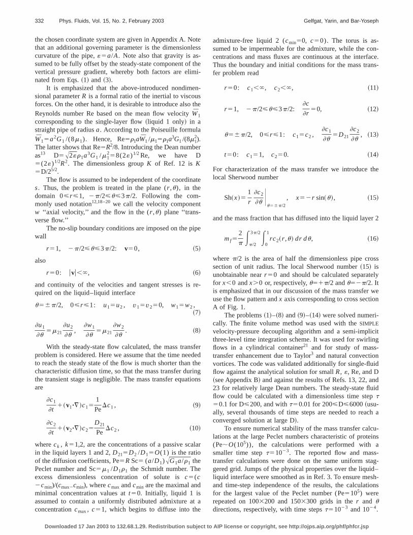
FIG. 2. Isolines of the axial velocityw~upper frames! and streamlines of thetransverse flow ~lower frames! forcocurrent flowG2151. The left-handside of each frame corresponds to thinner part of the toroidal boundary, thright-hand side to the outer part. Thcross-sectionB of Fig. 1 is shown.~a!R520 (D5179); ~b! R540 (D5716); ~c! R560 (D51610); ~d! R580 (D52862); ~e! R5100 (D54472). In all cases«50.1, m12
50.96.
ss00
er
e-
fo
im
-
e-andtoe
ty
be
un-es
No significant changes were found. Most of the matransfer results reported in the following refer to the 13200 grid andt51023.
Following Ref. 24 we define the characteristic turnovaveraging, and diffusion time asTe5(r1a/G1)1/2, Ta
5Td Pe22/3, Td5a2/D1 , respectively. Using, as before, thtime scale (r1a/G1)1/2, we obtain the following dimensionless values:Te51, Ta5Pe1/3, Td5Pe. In the calculationsreported in the following 103<Pe<105. The range of inte-gration in time for the mass-transfer problem was 200Pe5103, 1000 for Pe5104, and 10 000 for Pe5105, i.e., theintegration time was always longer than the averaging tand shorter than the diffusion time.
III. RESULTS AND DISCUSSION
In the calculations the parameterR was varied from 1 to100 or 120 and the Peclet number Pe from 103 to 105. Thus,
Downloaded 17 Jan 2003 to 132.68.1.29. Redistribution subject to AIP
-
,
r
e
the maximal Schmidt number Sc5Pe/R was 103 for R5100 and even larger for smallerR. The dimensionless curvature of the tube was typically taken as«50.1. The varia-tion of R in the range 1<R<120 corresponds to that of thDean number 0.45<D<6440. The other governing parameters were fixed. We considered the cases of cocurrentcountercurrent axial flow in the two layers, correspondingG2151 and21, respectively. In most of the calculations thfixed property ratios of the liquids were chosen asr21
51.4,m2150.96, andD2151.1, and the values of the densiand viscosity ratios were taken from the experiment.1 Sincethe physical properties of the two protein solutions shouldclose, the value ofD21 was chosen close to unity.
A. Flow patterns
The calculated flow patterns in the cocurrent and cotercurrent flows are plotted in Figs. 2 and 3. All the isolin
-l
e
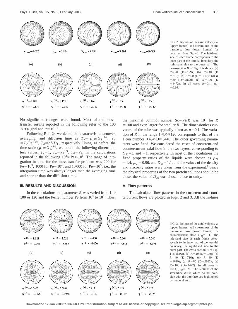
FIG. 3. Isolines of the axial velocityw~upper frames! and streamlines of thetransverse flow ~lower frames! forcountercurrent flow G21521. Theleft-hand side of each frame corresponds to the inner part of the toroidaboundary, the right-hand side to thouter part. The cross-sectionB of Fig.1 is shown.~a! R520 (D5179); ~b!R540 (D5716); ~c! R560 (D51610); ~d! R580 (D52862); ~e!R5100 (D54472). In all cases«50.1, m1250.96. The sections of thestreamlinec50, which do not coin-cide with the interface, are highlightedby numeral zero.
license or copyright, see http://ojps.aip.org/phf/phfcr.jsp
s.
334 Phys. Fluids, Vol. 15, No. 2, February 2003 Gelfgat, Yarin, and Bar-Yoseph
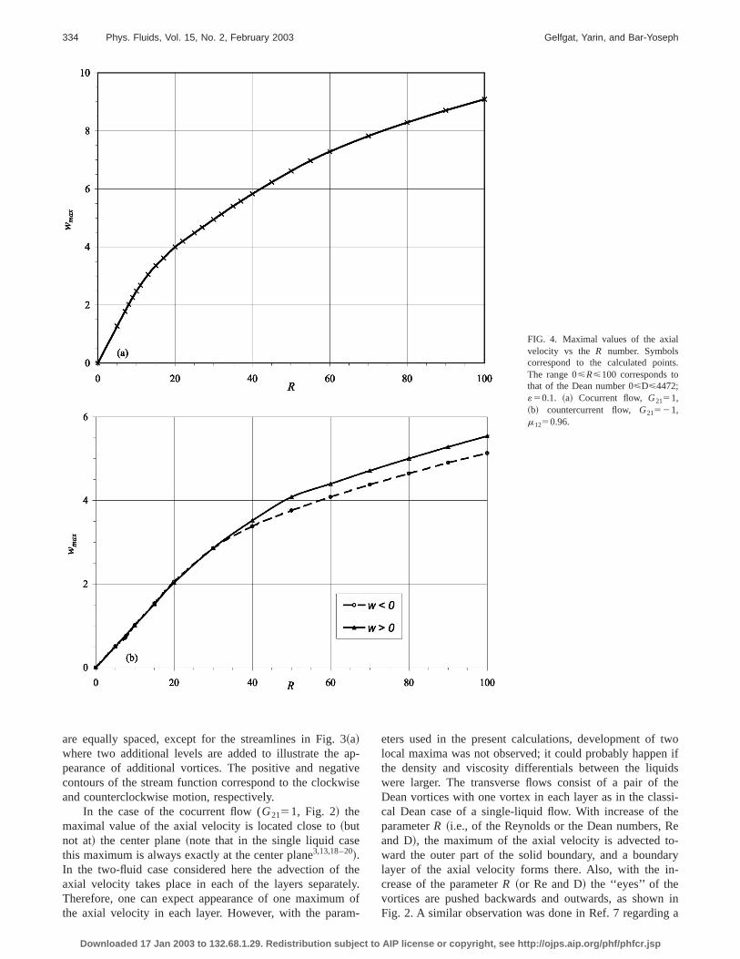
FIG. 4. Maximal values of the axialvelocity vs the R number. Symbolscorrespond to the calculated pointThe range 0<R<100 corresponds tothat of the Dean number 0<D<4472;«50.1. ~a! Cocurrent flow, G2151,~b! countercurrent flow, G21521,m1250.96.
3aptivis
e
thel
m
twon ifidsthessi-heReo-ary-
n ina
are equally spaced, except for the streamlines in Fig.~a!where two additional levels are added to illustrate thepearance of additional vortices. The positive and negacontours of the stream function correspond to the clockwand counterclockwise motion, respectively.
In the case of the cocurrent flow (G2151, Fig. 2! themaximal value of the axial velocity is located close to~butnot at! the center plane~note that in the single liquid casthis maximum is always exactly at the center plane3,13,18–20!.In the two-fluid case considered here the advection ofaxial velocity takes place in each of the layers separatTherefore, one can expect appearance of one maximumthe axial velocity in each layer. However, with the para
Downloaded 17 Jan 2003 to 132.68.1.29. Redistribution subject to AIP
-ee
ey.of-
eters used in the present calculations, development oflocal maxima was not observed; it could probably happethe density and viscosity differentials between the liquwere larger. The transverse flows consist of a pair ofDean vortices with one vortex in each layer as in the clacal Dean case of a single-liquid flow. With increase of tparameterR ~i.e., of the Reynolds or the Dean numbers,and D!, the maximum of the axial velocity is advected tward the outer part of the solid boundary, and a boundlayer of the axial velocity forms there. Also, with the increase of the parameterR ~or Re and D! the ‘‘eyes’’ of thevortices are pushed backwards and outwards, as showFig. 2. A similar observation was done in Ref. 7 regarding
license or copyright, see http://ojps.aip.org/phf/phfcr.jsp
r
335Phys. Fluids, Vol. 15, No. 2, February 2003 Dean vortices-induced enhancement
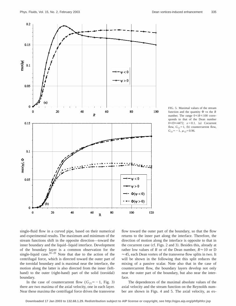
FIG. 5. Maximal values of the streamfunction and the quantityF vs theRnumber. The range 0<R<100 corre-sponds to that of the Dean numbe0<D<4472; «50.1. ~a! Cocurrentflow, G2151, ~b! countercurrent flow,G21521, m1250.96.
caththn
theoth
eer
owtheint
. Iteof
nlyter-
them-ex-
single-fluid flow in a curved pipe, based on their numeriand experimental results. The maximum and minimum ofstream functions shift in the opposite direction—towardinner boundary and the liquid–liquid interface. Developmeof the boundary layer is a common observation forsingle-liquid case.18–20 Note that due to the action of thcentrifugal force, which is directed toward the outer partthe toroidal boundary and is maximal near the interface,motion along the latter is also directed from the inner~left-hand! to the outer~right-hand! part of the solid~toroidal!boundary.
In the case of countercurrent flow (G21521, Fig. 3!there are two maxima of the axial velocity, one in each layNear these maxima the centrifugal force drives the transv
Downloaded 17 Jan 2003 to 132.68.1.29. Redistribution subject to AIP
leete
fe
r.se
flow toward the outer part of the boundary, so that the flreturns to the inner part along the interface. Therefore,direction of motion along the interface is opposite to thatthe cocurrent case~cf. Figs. 2 and 3!. Besides this, already arather low values ofR or of the Dean number,R'10 or D'45, each Dean vortex of the transverse flow splits in twowill be shown in the following that this split reduces thmixing of a passive scalar. Note also that in the casecountercurrent flow, the boundary layers develop not onear the outer part of the boundary, but also near the inface.
The dependences of the maximal absolute values ofaxial velocity and the stream function on the Reynolds nuber are shown in Figs. 4 and 5. The axial velocity, as
license or copyright, see http://ojps.aip.org/phf/phfcr.jsp
rteeed
cieta-bt
at
utit
ee
be
teivid
or
d bylhe
n-
axi-the
t
malfor
cur-heuidc-
teerralultson-ral-d onthanis aettesica-er-
ntlytte
ssofletefaron-ua-sedsed-m-
lu-eral
g
arre
336 Phys. Fluids, Vol. 15, No. 2, February 2003 Gelfgat, Yarin, and Bar-Yoseph
pected, increases monotonically~Fig. 4!; the increase is lin-ear at small values ofR,20 (D,179), where viscousdissipation is significant, and slows down at largerR ~orlarger D!.
As mentioned, in the case of cocurrent flow there issingle Dean vortex in each layer~Fig. 2!. The maximal valueof the stream function yields a coarse estimate of the vointensity, and consequently an estimate of the mixing spof a passive scalar inside the vortex. It was unexpectefound that in the cocurrent flow case the dependencmax(R) are nonmonotonic and reach a maximum at a cervalue of the parameterR @Fig. 5~a!#. Therefore the dependence of the mass transfer rate on the Reynolds numshould also be nonmonotonic, and indeed, we shall see infollowing that it also has a maximum at a certain modervalue ofR ~or D!.
In the case of countercurrent flow the maximal absolvalues of the stream function increase monotonically wthe Reynolds number@Fig. 5~b!#. However, in this case thercan be two vortices in each of the layers subdivided by stions of the streamlinec50, which do not coincide with theinterface~Fig. 3!, and part of the passive scalar shouldtransported through the boundary separating twosteadyvor-tices. Therefore, there is no direct relation between the insity of the strongest vortices and the mixing rate of a passscalar at the interface. To characterize the mixing rate insa vortex~Sec. III! we introduce the following measure:
F52
pSvortexucumax, ~17!
whereSvortex is the dimensionless area occupied by the vtex andp/2 is the total area of the layer~the dimensionlessradius of the pipe cross section is equal to 1!. The areaSvortex
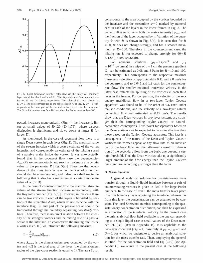
FIG. 6. Local Sherwood number calculated via the analytical boundlayer model forR51 and«50.01. The Reynolds and Dean numbers aRe50.125 and D50.141, respectively. The value ofD21 was chosen asD2151. The plot corresponds to the cross-sectionA of Fig. 1, x521 cor-responds to the outer part of the toroidal surface,x51—to the inner one.The Schmidt number was Sc5105 and thus the Peclet number Pe5105.
Downloaded 17 Jan 2003 to 132.68.1.29. Redistribution subject to AIP
a
xd
lys
in
erhee
eh
c-
n-ee
-
corresponds to the area occupied by the vortices boundethe interface and the streamlinec50 marked by numerazero in each of the layers in the lower frames in Fig. 3. Tvalue ofF is sensitive to both the vortex intensityucmaxu andthe fraction of the layer occupied by it. Variation of the quatity F with R is shown in Fig. 5~b!. It is seen that forR.60, F does not change strongly, and has a smooth mmum at R'100. Therefore in the countercurrent case,mixing rate is not expected to change strongly for 60<R<120 (1610<D<6440).
For aqueous solutions (r151 g/cm3 and m1
51022 g/(cm s)) in a pipe ofa51 cm the pressure gradienG1 can be estimated as 0.08 and 8 Pa/m forR510 and 100,respectively. This corresponds to the respective maxitransverse velocities of approximately 0.11 and 2.8 cm/sthe cocurrent, and to 0.045 and 1.9 cm/s for the counterrent flow. The smaller maximal transverse velocity in tlatter case reflects the splitting of the vortices in each fllayer in the former. For comparison, the velocity of the seondary meridional flow in a two-layer Taylor–Couetapparatus3 was found to be of the order of 0.6 cm/s undrealistic conditions, and the velocity of a two-layer natuconvection flow was estimated as 0.17 cm/s. The resshow that the Dean vortices in two-layer systems are strger than the corresponding Taylor–Couette or natuconvection counterparts. Thus novel bioseparators basethe Dean vortices can be expected to be more effectivethose based on the Taylor–Couette apparatus. This factconsequence of the nature of the Dean and Taylor–Couvortices: the former appear at any flow rate as an intrinpart of the basic flow, and the latter—as a result of bifurction of the secondary flow from the basic one beyond a ctain threshold. Thus the Dean vortices take up a significalarger amount of the flow energy than the Taylor–Coueones, and are accordingly stronger than the latter.
B. Mass transfer
A general analytical solution for quasistationary matransfer through a liquid–liquid interface between a paircounterrotating vortices is given in Ref. 4 for large Pecnumbers. In the case of Pe@1 the mass transfer takes placin a thin boundary layer adjoining the interface, whereasfrom this layer the concentration can be assumed to be cstant. The local Sherwood number, corresponding to the qsistationary concentration distribution, can then be expresas a function of the interfacial velocity. In the present cathe only analytical flow field available is the one corresponing to a single-liquid case at small values of the Dean nuber ~cf. ~B5!–~B9! in Appendix B!. It is appliable to thetwo-layer cocurrent (G2151) case only atr215m2151 andD→0, for which we undertake to derive an analytical sotion for the mass transfer rate. Then, employing the gensolution4 for the concentration field and Eq.~C19! ~see Ap-pendix C!, we arrive in the present case at the followinresult:
y
license or copyright, see http://ojps.aip.org/phf/phfcr.jsp
e
337Phys. Fluids, Vol. 15, No. 2, February 2003 Dean vortices-induced enhancement
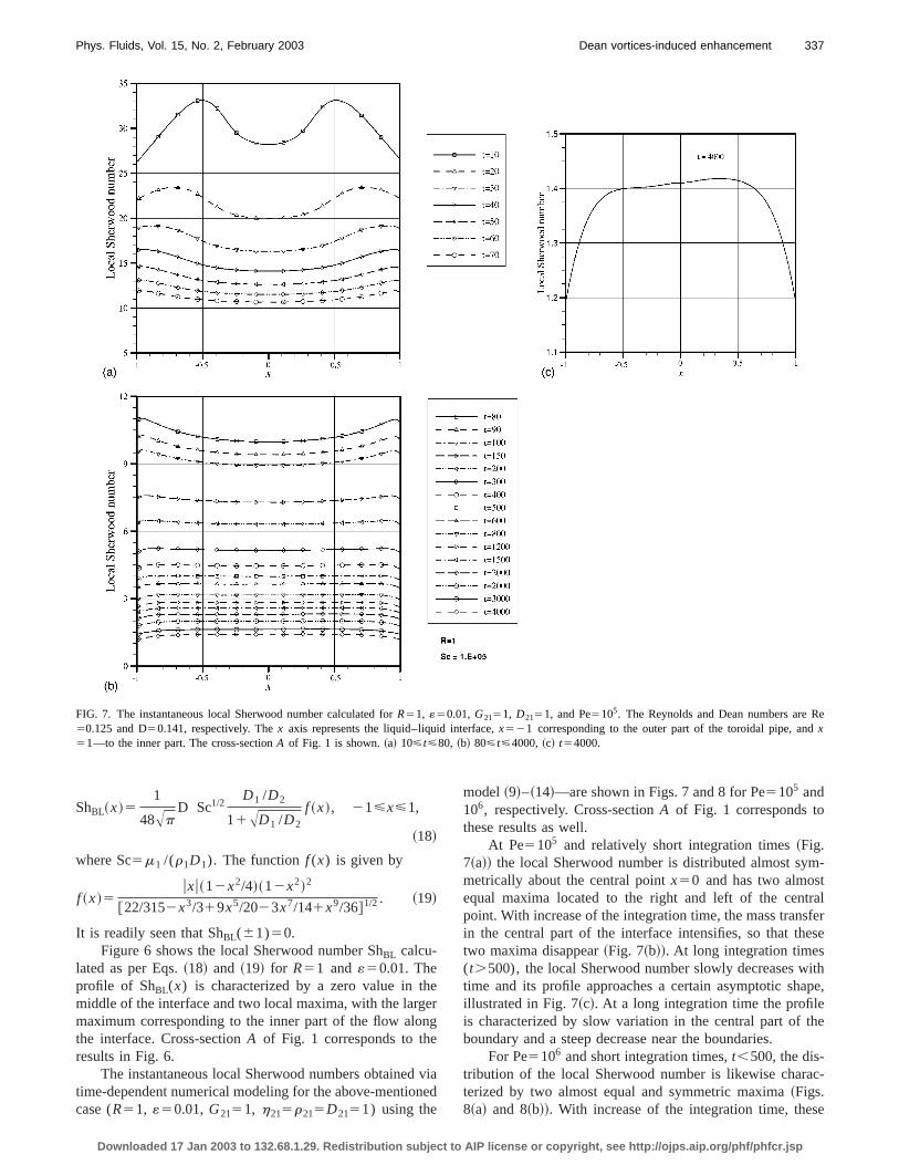
FIG. 7. The instantaneous local Sherwood number calculated forR51, «50.01, G2151, D2151, and Pe5105. The Reynolds and Dean numbers are R50.125 and D50.141, respectively. Thex axis represents the liquid–liquid interface,x521 corresponding to the outer part of the toroidal pipe, andx51—to the inner part. The cross-sectionA of Fig. 1 is shown.~a! 10<t<80, ~b! 80<t<4000,~c! t54000.
eeng
vne
m-tralfer
ese
ithpe,
he
c-
e
ShBL~x!51
48ApD Sc1/2
D1 /D2
11AD1 /D2
f ~x!, 21<x<1,
~18!
where Sc5m1 /(r1D1). The functionf (x) is given by
f ~x!5uxu~12x2/4!~12x2!2
@22/3152x3/319x5/2023x7/141x9/36#1/2. ~19!
It is readily seen that ShBL(61)50.Figure 6 shows the local Sherwood number ShBL calcu-
lated as per Eqs.~18! and ~19! for R51 and«50.01. Theprofile of ShBL(x) is characterized by a zero value in thmiddle of the interface and two local maxima, with the largmaximum corresponding to the inner part of the flow alothe interface. Cross-sectionA of Fig. 1 corresponds to theresults in Fig. 6.
The instantaneous local Sherwood numbers obtainedtime-dependent numerical modeling for the above-mentiocase (R51, «50.01,G2151, h215r215D2151) using the
Downloaded 17 Jan 2003 to 132.68.1.29. Redistribution subject to AIP
r
iad
model~9!–~14!—are shown in Figs. 7 and 8 for Pe5105 and106, respectively. Cross-sectionA of Fig. 1 corresponds tothese results as well.
At Pe5105 and relatively short integration times~Fig.7~a!! the local Sherwood number is distributed almost symetrically about the central pointx50 and has two almosequal maxima located to the right and left of the centpoint. With increase of the integration time, the mass transin the central part of the interface intensifies, so that thtwo maxima disappear~Fig. 7~b!!. At long integration times(t.500), the local Sherwood number slowly decreases wtime and its profile approaches a certain asymptotic shaillustrated in Fig. 7~c!. At a long integration time the profileis characterized by slow variation in the central part of tboundary and a steep decrease near the boundaries.
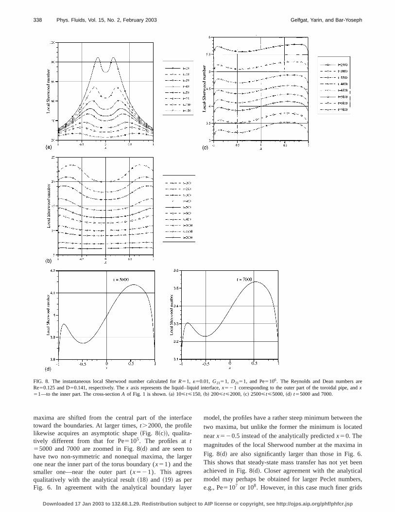
For Pe5106 and short integration times,t,500, the dis-tribution of the local Sherwood number is likewise charaterized by two almost equal and symmetric maxima~Figs.8~a! and 8~b!!. With increase of the integration time, thes
license or copyright, see http://ojps.aip.org/phf/phfcr.jsp
re
338 Phys. Fluids, Vol. 15, No. 2, February 2003 Gelfgat, Yarin, and Bar-Yoseph
FIG. 8. The instantaneous local Sherwood number calculated forR51, «50.01, G2151, D2151, and Pe5106. The Reynolds and Dean numbers aRe50.125 and D50.141, respectively. Thex axis represents the liquid–liquid interface,x521 corresponding to the outer part of the toroidal pipe, andx51—to the inner part. The cross-sectionA of Fig. 1 is shown.~a! 10<t<150, ~b! 200<t<2000,~c! 2500<t<5000,~d! t55000 and 7000.
c
g
e
the
d
in
6.beenalers,s
maxima are shifted from the central part of the interfatoward the boundaries. At larger times,t.2000, the profilelikewise acquires an asymptotic shape~Fig. 8~c!!, qualita-tively different from that for Pe5105. The profiles att55000 and 7000 are zoomed in Fig. 8~d! and are seen tohave two non-symmetric and nonequal maxima, the larone near the inner part of the torus boundary (x51) and thesmaller one—near the outer part (x521). This agreesqualitatively with the analytical result~18! and ~19! as perFig. 6. In agreement with the analytical boundary lay
Downloaded 17 Jan 2003 to 132.68.1.29. Redistribution subject to AIP
e
er
r
model, the profiles have a rather steep minimum between
two maxima, but unlike the former the minimum is locate
nearx520.5 instead of the analytically predictedx50. The
magnitudes of the local Sherwood number at the maxima
Fig. 8~d! are also significantly larger than those in Fig.This shows that steady-state mass transfer has not yetachieved in Fig. 8~d!. Closer agreement with the analyticmodel may perhaps be obtained for larger Peclet numbe.g., Pe5107 or 108. However, in this case much finer grid
license or copyright, see http://ojps.aip.org/phf/phfcr.jsp
d
n-
re
mthe
the
ionulkns
age
olds
nesulk
telyerseof
f. 3,con-
ncedherto
er-
rs
e,
339Phys. Fluids, Vol. 15, No. 2, February 2003 Dean vortices-induced enhancement
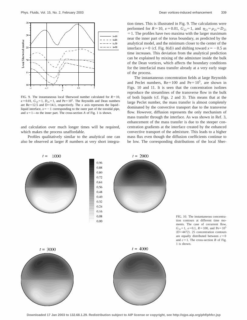
and calculation over much longer times will be requirewhich makes the process unaffordable.
Profiles qualitatively similar to the analytical one caalso be observed at largerR numbers at very short integra
FIG. 9. The instantaneous local Sherwood number calculated forR510,«50.01, G2151, D2151, and Pe5105. The Reynolds and Dean numbeare Re512.5 and D514.1, respectively. Thex axis represents the liquid–liquid interface,x521 corresponding to the outer part of the toroidal pipandx51—to the inner part. The cross-sectionA of Fig. 1 is shown.
Downloaded 17 Jan 2003 to 132.68.1.29. Redistribution subject to AIP
,
tion times. This is illustrated in Fig. 9. The calculations weperformed forR510, «50.01, G2151, andh215r215D21
51. The profiles have two maxima with the larger maximunear the inner part of the torus boundary, as predicted byanalytical model, and the minimum closer to the center ofinterfacex50 ~cf. Fig. 8~d!! and shifting towardx520.5 astime increases. This deviation from the analytical predictcan be explained by mixing of the admixture inside the bof the Dean vortices, which affects the boundary conditiofor the interfacial mass transfer already at a very early stof the process.
The instantaneous concentration fields at large Reynand Peclet numbers, Re5100 and Pe5105, are shown inFigs. 10 and 11. It is seen that the concentration isolireproduce the streamlines of the transverse flow in the bof both liquids ~cf. Figs. 2 and 3!. This means that at thelarge Peclet number, the mass transfer is almost compledominated by the convective transport due to the transvflow. However, diffusion represents the only mechanismmass transfer through the interface. As was shown in Reenhancement of the mass transfer is due to the steepercentration gradients at the interface created by the enhaconvective transport of the admixture. This leads to a higmass flux even though the diffusion coefficients continuebe low. The corresponding distributions of the local Sh
a-
,
FIG. 10. The instantaneous concentrtion contours at different time mo-ments. The case of cocurrent flowG2151, «50.1, R5100, and Pe5105
~D54472!. 25 concentration contoursare equally distributed betweenc50andc51. The cross-sectionB of Fig.1 is shown.
license or copyright, see http://ojps.aip.org/phf/phfcr.jsp
a-
nt
-
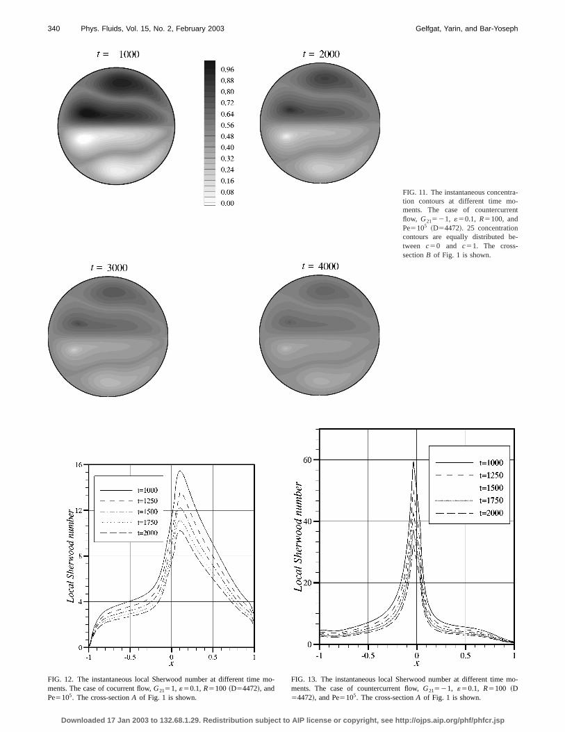
340 Phys. Fluids, Vol. 15, No. 2, February 2003 Gelfgat, Yarin, and Bar-Yoseph
FIG. 11. The instantaneous concentrtion contours at different time mo-ments. The case of countercurreflow, G21521, «50.1, R5100, andPe5105 ~D54472!. 25 concentrationcontours are equally distributed between c50 and c51. The cross-sectionB of Fig. 1 is shown.
m mo-
FIG. 12. The instantaneous local Sherwood number at different timements. The case of cocurrent flow,G2151, «50.1, R5100 ~D54472!, andPe5105. The cross-sectionA of Fig. 1 is shown.Downloaded 17 Jan 2003 to 132.68.1.29. Redistribution subject to AIP
o-FIG. 13. The instantaneous local Sherwood number at different timements. The case of countercurrent flow,G21521, «50.1, R5100 ~D54472!, and Pe5105. The cross-sectionA of Fig. 1 is shown.
license or copyright, see http://ojps.aip.org/phf/phfcr.jsp
s
341Phys. Fluids, Vol. 15, No. 2, February 2003 Dean vortices-induced enhancement
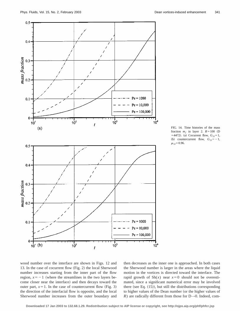
FIG. 14. Time histories of the masfraction mf in layer 2. R5100 ~D54472!. ~a! Cocurrent flow,G2151,~b! countercurrent flow, G21521,m1250.96.
an
owee
aa
casesuidhe-ed
g
wood number over the interface are shown in Figs. 1213. In the case of cocurrent flow~Fig. 2! the local Sherwoodnumber increases starting from the inner part of the flregion,x521 ~where the streamlines in the two layers bcome closer near the interface! and then decays toward thouter part,x51. In the case of countercurrent flow~Fig. 3!the direction of the interfacial flow is opposite, and the locSherwood number increases from the outer boundary
Downloaded 17 Jan 2003 to 132.68.1.29. Redistribution subject to AIP
d
-
lnd
then decreases as the inner one is approached. In boththe Sherwood number is larger in the areas where the liqmotion in the vortices is directed toward the interface. Trapid growth of Sh(x) near x50 should not be overestimated, since a significant numerical error may be involvthere~see Eq.~15!!, but still the distributions correspondinto higher values of the Dean number~or the higher values ofR) are radically different from those for D→0. Indeed, com-
license or copyright, see http://ojps.aip.org/phf/phfcr.jsp
e
342 Phys. Fluids, Vol. 15, No. 2, February 2003 Gelfgat, Yarin, and Bar-Yoseph
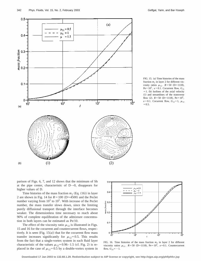
FIG. 15. ~a! Time histories of the massfractionmf in layer 2 for different vis-cosity ratiosm12 . R550 ~D51118!,Pe5105, «50.1. Cocurrent flow,G21
51. ~b! Isolines of the axial velocity~1! and streamlines of the transversflow ~2!. R550 ~D51118!, Pe5105,«50.1. Cocurrent flow,G2151, m12
50.5.
S
tine
bora
es
ye
n
parison of Figs. 6, 7, and 12 shows that the minimum ofat the pipe center, characteristic of D→0, disappears forhigher values of D.
Time histories of the mass fractionmf ~Eq. ~16!! in layer2 are shown in Fig. 14 forR5100 ~D'4500! and the Pecletnumber varying from 103 to 105. With increase of the Peclenumber, the mass transfer slows down, since the limitpurely diffusional transport through the interface becomweaker. The dimensionless time necessary to reach a90% of complete equilibration of the admixture concenttion in both layers can be estimated as Pe/10.
The effect of the viscosity ratiom12 is illustrated in Figs.15 and 16 for the cocurrent and countercurrent flows, resptively. It is seen~Fig. 15~a!! that for the cocurrent flow mastransfer increases significantly form1250.5. This resultsfrom the fact that a single-vortex system in each fluid lacharacteristic of the valuesm1250.96– 1.5~cf. Fig. 2! is re-placed in the case ofm1250.5 by a double-vortex system i
Downloaded 17 Jan 2003 to 132.68.1.29. Redistribution subject to AIP
h
gsut
-
c-
rFIG. 16. Time histories of the mass fractionmf in layer 2 for differentviscosity ratiosm12 . R550 ~D51118!, Pe5105, «50.1. Countercurrentflow, G21521.
license or copyright, see http://ojps.aip.org/phf/phfcr.jsp
343Phys. Fluids, Vol. 15, No. 2, February 2003 Dean vortices-induced enhancement
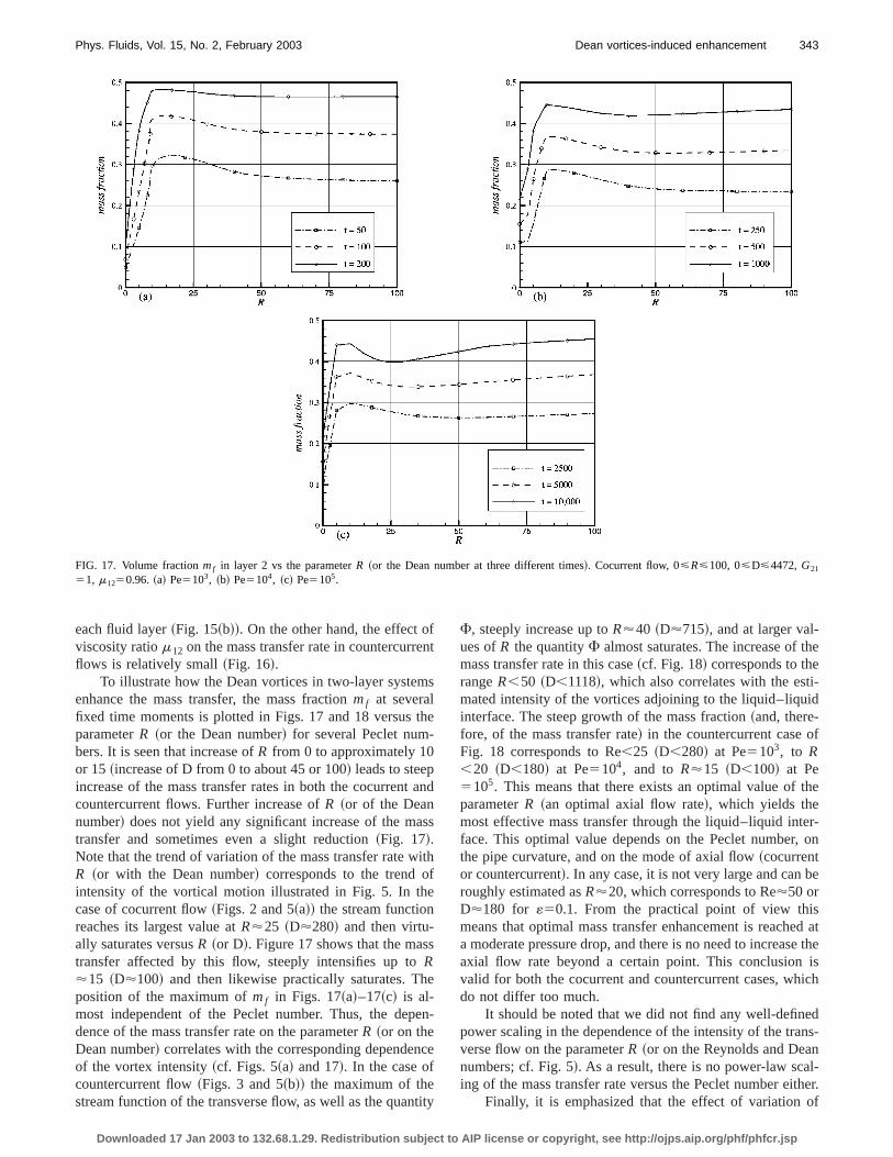
FIG. 17. Volume fractionmf in layer 2 vs the parameterR ~or the Dean number at three different times!. Cocurrent flow, 0<R<100, 0<D<4472,G21
51, m1250.96. ~a! Pe5103, ~b! Pe5104, ~c! Pe5105.
fn
m
th-
a
s
itfe
s
he
pe
c
ti
he
i-id
f
the
er-, on
be
sed ate theisich
edns-nl-ther.of
each fluid layer~Fig. 15~b!!. On the other hand, the effect oviscosity ratiom12 on the mass transfer rate in countercurreflows is relatively small~Fig. 16!.
To illustrate how the Dean vortices in two-layer systeenhance the mass transfer, the mass fractionmf at severalfixed time moments is plotted in Figs. 17 and 18 versusparameterR ~or the Dean number! for several Peclet numbers. It is seen that increase ofR from 0 to approximately 10or 15~increase of D from 0 to about 45 or 100! leads to steepincrease of the mass transfer rates in both the cocurrentcountercurrent flows. Further increase ofR ~or of the Deannumber! does not yield any significant increase of the matransfer and sometimes even a slight reduction~Fig. 17!.Note that the trend of variation of the mass transfer rate wR ~or with the Dean number! corresponds to the trend ointensity of the vortical motion illustrated in Fig. 5. In thcase of cocurrent flow~Figs. 2 and 5~a!! the stream functionreaches its largest value atR'25 ~D'280! and then virtu-ally saturates versusR ~or D!. Figure 17 shows that the mastransfer affected by this flow, steeply intensifies up toR'15 ~D'100! and then likewise practically saturates. Tposition of the maximum ofmf in Figs. 17~a!–17~c! is al-most independent of the Peclet number. Thus, the dedence of the mass transfer rate on the parameterR ~or on theDean number! correlates with the corresponding dependenof the vortex intensity~cf. Figs. 5~a! and 17!. In the case ofcountercurrent flow~Figs. 3 and 5~b!! the maximum of thestream function of the transverse flow, as well as the quan
Downloaded 17 Jan 2003 to 132.68.1.29. Redistribution subject to AIP
t
s
e
nd
s
h
n-
e
ty
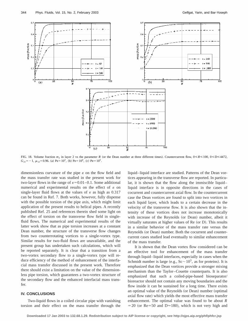
F, steeply increase up toR'40 ~D'715!, and at larger val-ues ofR the quantityF almost saturates. The increase of tmass transfer rate in this case~cf. Fig. 18! corresponds to therangeR,50 ~D,1118!, which also correlates with the estmated intensity of the vortices adjoining to the liquid–liquinterface. The steep growth of the mass fraction~and, there-fore, of the mass transfer rate! in the countercurrent case oFig. 18 corresponds to Re,25 ~D,280! at Pe5103, to R,20 ~D,180! at Pe5104, and to R'15 ~D,100! at Pe5105. This means that there exists an optimal value ofparameterR ~an optimal axial flow rate!, which yields themost effective mass transfer through the liquid–liquid intface. This optimal value depends on the Peclet numberthe pipe curvature, and on the mode of axial flow~cocurrentor countercurrent!. In any case, it is not very large and canroughly estimated asR'20, which corresponds to Re'50 orD'180 for «50.1. From the practical point of view thimeans that optimal mass transfer enhancement is reacha moderate pressure drop, and there is no need to increasaxial flow rate beyond a certain point. This conclusionvalid for both the cocurrent and countercurrent cases, whdo not differ too much.
It should be noted that we did not find any well-definpower scaling in the dependence of the intensity of the traverse flow on the parameterR ~or on the Reynolds and Deanumbers; cf. Fig. 5!. As a result, there is no power-law scaing of the mass transfer rate versus the Peclet number ei
Finally, it is emphasized that the effect of variation
license or copyright, see http://ojps.aip.org/phf/phfcr.jsp
344 Phys. Fluids, Vol. 15, No. 2, February 2003 Gelfgat, Yarin, and Bar-Yoseph
FIG. 18. Volume fractionmf in layer 2 vs the parameterR ~or the Dean number at three different times!. Countercurrent flow, 0<R<100, 0<D<4472,G21521, m1250.96. ~a! Pe5103, ~b! Pe5104, ~c! Pe5105.
fl
sitttlehtagehew
e-rfafoonean
gth
or-icu-–ofentin
thein-ally
ther-ent
beferthe
inglso
ator/thests
ert
dimensionless curvature of the pipe« on the flow field andthe mass transfer rate was studied in the present worktwo-layer flows in the range of«50.01–0.1. Some additionanumerical and experimental results on the effect of« onsingle-layer fluid flows at the values of« as high as 0.317can be found in Ref. 7. Both works, however, fully dispenwith the possible torsion of the pipe axis, which might limapplication of the present results to helical pipes. A recenpublished Ref. 25 and references therein shed some lighthe effect of torsion on the transverse flow field in singfluid flows. The numerical and experimental results of tlatter work show that as pipe torsion increases at a consDean number, the structure of the transverse flow chanfrom two counterrotating vortices to a single-vortex typSimilar results for two-fluid flows are unavailable, and tpresent group has undertaken such calculations, whichbe reported separately. It is clear that a transition fromtwo-vortex secondary flow to a single-vortex type will rduce efficiency of the method of enhancement of the intecial mass transfer discussed in the present work. Therethere should exist a limitation on the value of the dimensiless pipe torsion, which guarantees a two-vortex structurthe secondary flow and the enhanced interfacial mass trfer.
IV. CONCLUSIONS
Two-liquid flows in a coiled circular pipe with vanishintorsion and their effect on the mass transfer through
Downloaded 17 Jan 2003 to 132.68.1.29. Redistribution subject to AIP
or
e
lyon-entes.
illa
-re-ofs-
e
liquid–liquid interface are studied. Patterns of the Dean vtices appearing in the transverse flow are reported. In partlar, it is shown that the flow along the immiscible liquidliquid interface is in opposite directions in the casescocurrent and countercurrent axial flow. In the countercurrcase the Dean vortices are found to split into two vorticeseach liquid layer, which leads to a certain decrease invelocity of the transverse flow. It is also shown that thetensity of these vortices does not increase monotonicwith increase of the Reynolds~or Dean! number, albeit itvirtually saturates at higher values of Re~or D!. This resultsin a similar behavior of the mass transfer rate versusReynolds~or Dean! number. Both the cocurrent and countecurrent cases studied lead eventually to similar enhancemof the mass transfer.
It is shown that the Dean vortex flow considered canan effective tool for enhancement of the mass transthrough liquid–liquid interfaces, especially in cases whenSchmidt number is large~e.g., Sc;103, as for proteins!. It isemphasized that the Dean vortices provide a stronger mixmechanism than the Taylor–Couette counterparts. It is aemphasized that such a coiled-pipe-based bioseparbioreactor should not contain any moving boundaries andflow inside it can be sustained for a long time. There exian optimal value of the Reynolds~or Dean! number~optimalaxial flow rate! which yields the most effective mass transfenhancement. The optimal value was found to be abouR520 ~or Re550 and D'180!, which is not very high and
license or copyright, see http://ojps.aip.org/phf/phfcr.jsp
foP
-
in
un-
e
345Phys. Fluids, Vol. 15, No. 2, February 2003 Dean vortices-induced enhancement
can be easily reached in practice. No definite scaling lawthe diffused mass fraction versus the Reynolds, Dean, orclet numbers was found.
ACKNOWLEDGMENTS
This research was supported by BSF~US–Israel Bina-tional Science Foundation! Grant No. 97-118, the Israel Ministry of Immigrant Absorption~to A.Yu.G.!, and by the IsraelHigh Performance Computer Unit.
APPENDIX A: CONTINUITY, MOMENTUM, AND MASSTRANSFER EQUATIONS IN HELICALCOORDINATES „r ,u,s …
The Lamecoefficients of the coordinate system shownFig. 1 are
Downloaded 17 Jan 2003 to 132.68.1.29. Redistribution subject to AIP
re-
hr51, hu5r , hs511«r sinu. ~A1!
The corresponding equations can be derived from their coterparts in general orthogonal curvilinear coordinates~see,for example Ref. 17!. Assuming ]/]s[0, the continuityequation reads
]
]r@r ~11«r sinu!u#1
]
]u@~11«r sinu!v#50; ~A2!
the r , u, ands projections of the momentum equations ar
]u
]t1u
]u
]r1
vr
]u
]u2
v2
r2
« sinu
11«r sinuw252
]p
]r1
1
R H ]
]r F 1
r ~11«r sinu!
]
]r@r ~11«r sinu!u#G1
1
r 2~11«r sinu!
]
]u
3F ~11«r sinu!]u
]uG22
r 2
]v]u
2«cosu1«r sin~2u!
r ~11«r sinu!2 v2«2cosu
~11«r sinu!3 wJ ,
~A3!
]v]t
1u]v]r
1vr
]v]u
1uvr
2« cosu
11«r sinuw2
521
r
]p
]u1
1
R H 1
11«r sinu
]
]r F1
r~11«r sinu!
]~rv !
]r G1
1
r 2
]
]u F 1
11«r sinu
]
]u@~11«r sinu!v#G1
2
r 2
]u
]u1«
cosu
r ~11«r sinu!2 u1«2«r 1sinu
~11«r sinu!3 wJ , ~A4!
erse
in
]w
]t1u
]w
]r1
vr
]w
]u1
« sinu
11«r sinuuw1
« cosu
11«r sinuvw
52Gi11
R H 1
r
]
]r F r
11«r sinu
]
]r@~11«r sinu!w#G
11
r 2
]
]u F 1
11«r sinu
]
]u@~11«r sinu!w#G
1«2cosu
~11«r sinu!3 u2«2«r 1sinu
~11«r sinu!3 vJ , ~A5!
whereGi51 or G21 for liquids 1 and 2, respectively.Note that Re5R2/8, and D58(2«)1/2 Re5(2«)1/2R2.The mass transfer equation is
]c
]t1u
]c
]r1
vr
]c
]u
51
PeH 1
r
]~rc !
]r1
1
r 2
]2c
]u2 1« sinu
11«r sinu
]c
]r
1« cosu
11«r sinu
1
r
]c
]uJ . ~A6!
The stream functionc of the transverse flow is given by
u51
r ~11«r sinu!
]c
]u, v52
1
11«r sinu
]c
]r, ~A7!
and is rendered dimensionless by (G1a3/r1)1/2.
APPENDIX B: ANALYTICAL SOLUTIONFOR THE FLOW FIELD IN A SINGLE-LIQUID CASEFOR SMALL CURVATURE
To derive the analytical solution for small curvature wassume that the axial velocity is of order 1 and the transveflow of order«. Thus, separating all the terms of order 1Eq. ~A5! and all those of order« in Eqs. ~A2!–~A4!, wearrive at the following equations.The continuity equation
1
r
]~ru !
]r1
1
r
]v]u
50, ~B1!
and the momentum equations
2]p
]r1
1
R H ]
]r F1
r
]~ru !
]r G11
r 2
]2u
]u2 22
r 2
]v]uJ 52«w2 sinu,
~B2!
license or copyright, see http://ojps.aip.org/phf/phfcr.jsp
-
m
n1
fa
-
e
re
:
346 Phys. Fluids, Vol. 15, No. 2, February 2003 Gelfgat, Yarin, and Bar-Yoseph
21
r
]p
]u1
1
R H ]
]r F1
r
]~rv !
]r G11
r 2
]2v]u2 1
2
r 2
]u
]uJ52«w2 cosu, ~B3!
2111
R
1
r
d
dr F rdw
dr G50. ~B4!
Equations~B1!–~B4! must be solved with the no-slip boundary condition atr 51. The solution is13,16
w5R
4~12r 2!, ~B5!
u5«R3
1152S 12r 2
4 D ~12r 2!2 sinu, ~B6!
v52«R3
4608~r 221!~7r 4223r 214!cosu, ~B7!
p5«R2
192r ~2r 426r 219!sinu. ~B8!
This solution corresponds to small values of the Dean nuber D58(2«)1/2Re5(2«)1/2R2. The dimensionless streamfunction of the flowc is given by ~A7!, ~B6!, and ~B7! inthis limit ~«→0! as per
c52«R3
1152r S 12
r 2
4 D ~12r 2!2 cosu, ~B9!
where it is rendered dimensionless by (G1a3/r1)1/2.
APPENDIX C: CALCULATION OF THE SHERWOODNUMBER WITHIN THE FRAMEWORK OF THEBOUNDARY LAYER MODEL
We assume that the admixture concentration varies oin a thin boundary layer near the interface in both liquidsand 2, which is a plausible approximation based on thethat Sc@1. In the present caseck5ck(r ,u) and the dimen-sionless Eqs.~9! and ~10! in the boundary layer approximation take the form
«Uk
]ck
]r1«
Vk
r
]ck
]u5
1
Pek
1
r 2
]2ck
]u2 , ~C1!
where«Uk5uk and«Vk5vk are theu andv velocity com-ponents in thekth layer, respectively, and Pek are the Pecletnumbers defined as Pek5W1a1 /Dk . In the present case wassumer215m2151, as well asG2151. As a result,U1
5U25U and V15V25V. According to Eqs.~B6!, ~B7!,and ~B9!,
U5A~r !
rsinu, ~C2!
V5dA
drcosu, ~C3!
A~r !5Re
18r S 12
r 2
4 D ~12r 2!2. ~C4!
At the interfaceu57p/2, Eq. ~C1! takes the form
Downloaded 17 Jan 2003 to 132.68.1.29. Redistribution subject to AIP
-
ly
ct
«PekS 2A
r
]ck
]x6
dA/dr
ry
]ck
]y D5]2ck
]y2 , ~C5!
where Eqs.~C2! and~C3! were used and the coordinatey isnormal to x ~normal to the interface; the coordinates adimensionless!. Since at the interfaceu57p/2 we havex56r , and Eq.~C5! can be rearranged to the following form
]2ck
]y2 1Pk~x!y]ck
]y5Qk~x!
]ck
]x, ~C6!
where
Pk5«PekS 7dA/dr
r DQk52«Pek
A
r
J at u57p/2. ~C7!
Solution of Eq.~C6! is subject to the following boundaryconditions:
y52`, c25c`2 , ~C8!
y51`, c15c`1 , ~C9!
y50, 2D2
]c2
]y52D1
]c1
]y, ~C10!
y50, c15c2 , ~C11!
and solution of the problem~C6!–~C11! yields4
c25c`21kc`1
11k2
k~c`22c`1!
11kerfS Z
2D , ~C12!
c15c`21kc`1
11k2
~c`22c`1!
11kerfS Z
2D , ~C13!
where
k5D2121/2, ~C14!
Z5yF E1
x eW(j)2W(x)
Qk~j!djG1/2
, ~C15!
W~x!52Econst
x Pk~j!
Qk~j!dj. ~C16!
Given Eqs.~C4!, ~C7!, and~C16!, we find
W~j!2W~x!52 lnFj~12j2/4!~12j2!2
x~12x2/4!~12x2!2G ~C17!
for u57p/2.Therefore the mass fluxj 252(D2 /a)]c2 /]yuy50 is
found from ~C12!, ~C15!, and~C17! as
j 25D2
aAp
k~c`22c`1!
11k
3F «Pe2~Re/18!x2~12x2/4!2~12x2!4
22/3152x3/319x5/2023x7/141x9/36G1/2
.
~C18!
Obviously, j 15 j 2 . The Sherwood number is defined as
license or copyright, see http://ojps.aip.org/phf/phfcr.jsp
n
e
ssJ
f auid
s i
llti
xis
ingns
ce
aro-
ionol.
d
A
al
s.
d
ic
i-th-
nd
nd’’
in
ed
ed
a,
347Phys. Fluids, Vol. 15, No. 2, February 2003 Dean vortices-induced enhancement
ShBL~x!5j 2a
~c`22c`1!D2, ~C19!
which yields, with the aid of Eq.~C18!, the expressions~18!and ~19!.
1G. Baier, T. M. Grateful, M. D. Graham, and E. N. Lightfoot, ‘‘Predictioof mass transfer rates in spatially periodic flows,’’ Chem. Eng. Sci.54, 343~1999!.
2G. Baier, M. D. Graham, and E. N. Lightfoot, ‘‘Mass transport in a novtwo-fluid vortex extractor,’’ AIChE J.46, 2395~2000!.
3A. L. Yarin, A. Yu. Gelfgat, and P. Z. Bar-Yoseph, ‘‘Enhancement of matransfer in a two-layer Taylor–Couette apparatus with axial flow,’’ Int.Heat Mass Transf.45, 555 ~2002!.
4A. L. Yarin, ‘‘Stationary d.c. streaming due to shape oscillations odroplet and its effect on mass transfer in liquid–liquid interfaces,’’ J. FlMech.444, 321 ~2001!.
5A. L. Yarin, ‘‘Steady streaming and mass transfer due to capillary wavea two-layer system,’’ Fluid Dyn. Res.31, 79 ~2002!.
6K. Y. Chung, M. E. Brewster, and G. Belfort, ‘‘Dean vortices with waflux in a curved channel membrane system. 3. Concentration polarizain a spiral reverse osmosis slit,’’ J. Chem. Eng. Jpn.31, 683 ~1998!.
7H. Mullubhotla, G. Belfort, W. A. Edelstein, and T. A. Early, ‘‘Dean vortestability using magnetic resonance flow imaging and numerical analysAIChE J.47, 1126~2001!.
8J. J. Sillekens, C. C. M. Rindt, and A. A. van Steenhoven, ‘‘Developmixed convection in a coiled heat exchanger,’’ Int. J. Heat Mass Tra41, 61 ~1998!.
9N. Acharya, M. Sen, and H.-C. Chang, ‘‘Analysis of heat transfer enhanment in coiled-tube heat exchangers,’’ Int. J. Heat Mass Transf.44, 3189~2001!.
10S. Lugue, H. Mallubhotla, G. Gehlert, R. Kuriel, S. Dzengeleski, S. Peand G. Belfort, ‘‘A new coiled hollow-fiber module for enhanced micrfiltration performance in biotechnology,’’ Biotechnol. Bioeng.65, 247~1999!.
Downloaded 17 Jan 2003 to 132.68.1.29. Redistribution subject to AIP
l
.
n
on
,’’
f.
-
l,
11T. Kluge, C. Rezende, D. Wood, and G. Belfort, ‘‘Protein transmissduring Dean vortex microfiltration of yeast suspensions,’’ BiotechnBioeng.65, 649 ~1999!.
12S. A. Berger and L. Talbot, ‘‘Flow in curved pipes,’’ Annu. Rev. FluiMech.15, 461 ~1983!.
13T. J. Pedley,Fluid Mechanics of Large Blood Vessels~Cambridge Univer-sity Press, Cambridge, 1980!.
14W. R. Dean, ‘‘Fluid in a curved channel,’’ Proc. R. Soc. London, Ser.121, 402 ~1928!.
15A. Yu. Gelfgat, A. L. Yarin, and P. Z. Bar-Yoseph, ‘‘Three-dimensioninstability of a two-layer Dean flow,’’ Phys. Fluids13, 3185~2001!.
16W. R. Dean, ‘‘The stream-line motion of fluid in a curved pipe,’’ PhiloMag. 5, 673 ~1928!.
17M. Germano, ‘‘On the effect of torsion on a helical pipe flow,’’ J. FluiMech.125, 1 ~1982!.
18L. Zabielski and A. J. Mestel, ‘‘Steady flow in a helically symmetrpipe,’’ J. Fluid Mech.370, 297 ~1998!.
19T. J. Huttl, C. Wagner, and R. Friedrich, ‘‘Navier-Stokes solutions of lamnar flows based on orthogonal helical coordinates,’’ Int. J. Numer. Meods Fluids29, 749 ~1999!.
20Y. Fan, R. I. Tanner, and N. Phan-Thien, ‘‘Fully developed viscous aviscoelastic flows in curved pipes,’’ J. Fluid Mech.44, 327 ~2001!.
21A. Yu. Gelfgat, P. Z. Bar-Yoseph, and A. Solan, ‘‘Vortex breakdown ainstability of swirling flow in a cylinder with rotating top and bottom,Phys. Fluids8, 2614~1996!.
22W. M. Collins and S. C. R. Dennis, ‘‘The steady motion of viscous fluida curved tube,’’ Q. J. Mech. Appl. Math.28, 133 ~1975!.
23D. J. McConaloque and R. S. Srivastava, ‘‘Motion of fluid in a curvtube,’’ Proc. R. Soc. London, Ser. A307, 37 ~1968!.
24P. B. Rhines and W. R. Young, ‘‘How rapidly is a passive scalar mixwithin closed streamlines?’’ J. Fluid Mech.133, 133 ~1983!.
25K. Yamamoto, A. Aribowo, Y. Hayamizu, T. Hirose, and K. Kawahar‘‘Visualization of the flow in a helical pipe,’’ Fluid Dyn. Res.30, 251~2002!.
license or copyright, see http://ojps.aip.org/phf/phfcr.jsp