Dealing with the Challenges of Internet and Intranet ...
24
800-22565V1 4/19 Rev. A I AlarmNet-I Services Dealing with the Challenges of Internet and Intranet Communications (April 2019)
Transcript of Dealing with the Challenges of Internet and Intranet ...

800-22565V1 4/19 Rev. A
I AlarmNet-I Services
Dealing with the Challenges of
Internet and Intranet
Communications (April 2019)


Table of Contents
AlarmNet’s® IP Communications Review
Overview..................................................................... 1
Internet Communications ................................. 1
Data Security ........................................................... 1
Transport Layer Security .................................. 1
Advanced Encryption Standard .................. 2
Encryption ................................................................ 2
Algorithm Flexibility ............................................ 2
Key Management ................................................. 3
Firewalls and Their Challenges .................... 3
IP Communications
Network Config. & Reporting Path ................. 5
Message Reporting Path................................. 5
Static or DHCP Settings ................................... 5
Intranet Communications
Introduction ............................................................. 6
The Intranet Challenge ....................................... 6
About Private Network Applications ......... 7
Communication Traffic .................................... 7
Intranet Encrypted Communications ........... 8
Installation Key ...................................................... 8
Registration ............................................................. 8
Recovery Mode ...................................................... 9
AlarmNet’s® Approach for Internet Communications
Internet (IP Communicators) ......................... 10
Introducing AlarmNet-i® ............................... 10
Internet Communication Modules.............. 11
Installation-Protected Premises.............. 11
Resideo IP Central Station Receiver ...... 11
Installation at the Central Station ........... 11
Establishing a Link with AlarmNet-i ...... 12
Putting It All Together .................................... 13
Description of Figure 7 ............................... 13
IP Communicator Messages
Communicator Notifications/Failures ...... 14
Device Communication Failures .................. 15
Central Station Failures ................................... 15
LTE Cellular Platform
Introduction ........................................................... 16
LTE, GPRS, EDGE, ECDMA and 1XRTT Data
Connect Service ................................................... 16
Short Messaging Service (SMS) ................... 16
Cellular Communications ............................... 17
Cellular Based ..................................................... 17
Remote Services Communications ....... 17
Table of FiguresFigure 1: IP Reporting Path ..................................... 5
Figure 2: Intranet Communications................... 7
Figure 3: Intranet Registration Process ........... 8
Figure 4: Intranet Recovery Mode ....................... 9
Figure 5: Link with AlarmNet-i ............................ 12
Figure 6: Link with central station .................... 13
Figure 7: Putting It All Together ......................... 13
Figure 8: Network Com. Failure ......................... 15
Figure 9: Central Station Com. Failure .......... 15
Figure 10: LTE Communication Path ............ 17


PAGE 1
AlarmNet’s® IP Communications Review
Overview
This white paper provides a basic background of the AlarmNet-i network. For readers already
familiar with AlarmNet, this document is a solid reference point in understanding the Internet
based services of AlarmNet-i. For those not yet familiar with AlarmNet, a complete explanation
is available in the “Resideo Communication Solution”.
Internet Communications
Data Security
Resideo realized during its development process that data security and authentication are
critical requirements of any Internet based service that would send alarm information over IP
communication using the Internet or Intranet. Therefore, Resideo raised the bar and added
special emphasis on making these objectives a key part of the AlarmNet-i service.
Securing data over an IP connection is accomplished using many different methods, such as
Advanced Encryption Standard (AES) or Transport Layer Security (TLS). Today, the most
advanced and common industry method deployed is TLS. One such use is to secure financial
transactions over the Internet. It uses both a scheme for encryption as well as authentication.
Let’s define these two terms because they will become important, as we compare them to the
advanced techniques offered by the AlarmNet-i service.
Encryption Allows data to be altered in a way that both the sender and receiver can
understand it, but if captured during transmission would not be
meaningful to the intruder.
Authentication A process whereby the sending or receiving party can test and confirm that
the other recipient is who they claim to be.
Transport Layer Security
It is through a combination of both encryption and authentication that a robust and secure
system is achieved. As we mentioned earlier, TLS uses both encryption and authentication.
The weak aspect of implementing TLS is the authentication is only one-way. Let’s give an
example of what one-way authentication means so it is clear.

PAGE 2
Example
Purchasing from a business website that is said to be “secure” (typically using
TLS), requires the company to authenticate themselves. It assures you that no
other intruder is posing as the company you are about to buy something from.
This is clearly a desirable feature since nobody wants to send credit card
information over the Internet to a potentially fraudulent site posing as a reputable
business.
The weakness of this approach (for sending an alarm signal over the Internet) is that there is no
authentication the other way. Using our example above, the user who is making a purchase
over the Internet is confident that he or she is buying it from the company they claim to be.
However, the company has no assurances as to the validity that the customer is who he or she
claims to be.
Advanced Encryption Standard
The delivery of alarm information to central station needs to be a secure transaction and it is
imperative the central station and protected premises is who they say they are. Neither can
afford to be substituted! This “two-way” authentication is one of the enhanced security
features provided by the AlarmNet-i® Internet communications service. It assures that both the
protected premises and the central station are who they say they are.
Encryption
Data encryption can be accomplished using many different methods. These methods differ
and there is no one right way to encrypt data. What is important in selecting a scheme for
encryption is:
• It assumes an attacker has access to the algorithm that encrypts the data
• It can withstand attacks by fast and powerful computers
• It be publicly available and scrutinized by professionals as being secure
Resideo has chosen to build its encryption solution on a publicly available scheme called
Advanced Encryption Standards (AES). This powerful scheme was designed by cryptologists
Joan Daemen and Vincent Rijmen to be fast, compact and simple. It uses a basic key that can
be as large as 256 bits. AES is the approved cryptographic standard for the United States
Government. Resideo has had its implementation of AES validated and approved by the
National Institute of Standards and Technology (NIST).
Algorithm Flexibility
It must be stated that all of the AlarmNet-i communication modules are capable of being
changed/updated since they have flash memory. This flexibility has been incorporated so that
as encryption technology evolves Resideo can keep up with the latest advanced schemes.
These changes will have no impact on the security equipment or central station operations. It
assures you that the highest levels of data encryption and authentication can be used without
the need for equipment or operational changes at the central station.

PAGE 3
Key Management
Now that you have a basic idea of encryption and authentication we must introduce the
concept of the “key” that we mentioned earlier. A key is nothing more than a secret block of
data that is needed to understand how the received data was encoded or decrypted.
Sometimes different keys are used to encrypt and decrypt but it is important to note that solid
encryption solutions involve the storage and management of one or more of these “keys”. Each
side of the communication scheme (protected premises and central station) need to know
which keys to use or else communications fails.
Resideo AlarmNet-i® service removes the burden of this key management from large private
businesses or security installation companies. All Internet communication devices provided
under the AlarmNet-i umbrella have secure keys embedded within the AlarmNet-i system
maintains all key data. The keys are unique to each device and have no correlation with any
identifiers in the device.
What this means is that all of the administrative burden of setting up initial secure
communications from a protected premises to a central station have been lifted from the
installing dealer or central station.
Firewalls and Their Challenges
The Internet poses another concern, which is the increasing number of corporate (and
residential) firewalls. A firewall is designed to protect the user from attack over the Internet as
it provides anonymity to others on the Internet. This is highly desirable, particularly when the
user is connected to the Internet through an always-on connection (ADSL, satellite or cable
modem). The presence of a firewall does however pose real problems for installers trying to
quickly and easily install an alarm device that needs to communicate over the Internet.
Today it takes people knowledgeable of networks and firewalls to install communication
devices properly. Realizing that traditional alarm installation companies often do not have this
expertise in-house, a key objective of a Resideo Internet communication device must be the
easy set-up and installation, even behind firewalls and accomplishing the installation with
existing security dealer technicians.
With AlarmNet-i, the installation has been simplified. The installer need only know how to
physically connect a common Cat-5/6e wire or through Wi-Fi® between our communication
equipment and the LAN hub or Router that provides a path to the Internet. The
communications equipment is “smart” and finds its way to the AlarmNet-i service. This basic
capability cannot be overemphasized. Without this capability, significant technical knowledge
and understanding is needed to attempt to properly setup and maintain an Internet
connection behind firewalls.

PAGE 4
IP Communications Internet based communication requirements for Resideo/AlarmNet® communicators are as
follows:
• Devices communicate outbound to one of four predetermined IP addresses (defined below)
on port 443. All data is encrypted using an AES encryption logic.
• Devices are capable of using DHCP or Static IP
• Devices in the field sends a Media Access Control (MAC), or hardware address, ping to on
port 443 every 20 seconds
• All inbound and outbound traffic between the device and AlarmNet Network Control Center
(NCC) is fully encrypted
• Each device’s MAC has a unique encryption key. AlarmNet has the matching key at its NCC,
and the key is transmitted between the two points.
For a session to occur the end user logs into a security HTTPS web site, which is hosted at
the AlarmNet NCC. Once the device checks in, the device is instructed to establish a Secure
Socket Layer (SSL) connection with a server at a predefined IP address based on the
function the end-user is requesting.
The use of this method allows the device to establish connection outbound, but we cannot
establish a session inbound to the device.
• The device is operating with a private written code set and is not vulnerable to attack by
hackers or virus.
• Bandwidth:
� Standby: 25 byte per second
� Alarm: 1 Kbyte per second
NOTE: The following rules to the firewall have to be made at each client site and to allow
for control communications.
Server Name Server Purpose Server IP Address Server URL Ports
Redir 1 Alarm Signals 204.141.57.100 auiredir1.alarmnet.com 80 and 443
Redir 2 Alarm Signals 204.141.57.101 auiredir2.alarmnet.com 80 and 443
Redir 3 Alarm Signals 12.149.218.73 auiredir3.alarmnet.com 80 and 443
Control Server Tells device where
to connect 204.141.58.115 controlserver.alarmnet.com 80 and 443
Data Server1 Compass
Download Session 204.141.58.80 dataserver1.alarmnet.com 80 and 443
Data Server2 Compass
Download Session 204.141.58.81 dataserver2.alarmnet.com 80 and 443

PAGE 5
Network Config. & Reporting Path
Ports configured are set as outbound traffic only. All Internet communications flow through
Resideo’s Servers when a control’s configuration or code change is requested.
Message Reporting Path
1. Resideo directs the control to the Data Servers
2. Control initiates an outbound communication to the Data Server
3. A session is setup to receive the updates
4. IP communicators initiate contact with the above “Redir” servers every 20 seconds
ALARMNET COMMUNICATOR
OUTBOUND MAC PINGS
AND DATA ENCRYPTED
WITH UNIQUE KEY ON
PORT 443 (SSL)
DATA IS DECRYPTED USING THE
UNIQUE KEY AND THEN SENT
TO THE CENTRAL STATION OR
A COMMUNCATION SESSION
IS OPENED.
NO OUTBOUND
REQUESTS OR
CONNECTIONS ARE
ORIGINATED BY
ALARMNET.
CENTRAL STATION / END USER LOGS
INTO HTTPS ALARMNET WEB
SITES FOR TOTAL CONNECT 2 /
COMPASS AND PROGRAMMERLESS
REGISTRATION SESSIONS.
FIREWALL
ALARMNET NCC SERVERS
INTERNETAlarmNetWP-001-V1
NO INBOUND
PORTS ARE
REQUIRED TO
BE OPENED.
SECURE COMMUNICATIONS
Figure 1: IP Reporting Path
Static or DHCP Settings
AlarmNet Internet product communicators are capable of DHCP (automatic IP addressing) or
Static IP addressing (manual IP addressing). If problems occur due to automatic IP releasing∗
on the network, the AlarmNet device should be switched to Static IP communication.
If Static IP’s are being used, the following information is needed from the Network
Administrator before installation:
• Static IP address for the AlarmNet device
• Subnet Mask
• Default Gateway
• DNS IP Address
*Automatic IP Releasing: AlarmNet Internet products ping AlarmNet every 20 seconds to
verify connectivity; therefore, it releases the previously assigned IP
address at the end of its session and requests a new one each
time it checks connectivity.
NOTE: There are additional configuration requirements if the Resideo IP camera solution is
to be used.

PAGE 6
Intranet Communications
Introduction
Let’s focus on applications involving alarm signal transmission over or to a private Local Area
Network (LAN) or Wide Area Network (WAN). Many large private networks exist where the
security director wishes to receive alarm signals inside the network. Applications include
banks, larger retail chains, and corporate and college campuses where significant networks are
already in place and are being used for multiple purposes.
These alarm signals can either be in addition to or in place of Central Station services. In either
case, alarms arrive at a destination within the private LAN or WAN.
The Intranet Challenge
Any network system can be viewed from a data-security standpoint by analyzing the potential
points of attacks available in the system. Although many people believe that the Internet is
harder to protect against outside attacks, in reality a LAN or WAN based system is likely to be
more vulnerable to attack.
In a typical LAN environment within a company, there are many computers that are directly
connected to it. It is also common that most corporate data is sent over that network without
concern that it be encrypted. Most data produced by general applications running on a
corporate LAN do not get protected to this extent.
Data attacks at any one of the direct or dial-in LAN ports can quite easily be accomplished by
technical people with an idea toward listening to alarm signals or commands and later using
this information to compromise the security system.
A design goal when Resideo developed its LAN based alarm reporting solutions, was to provide
as much data security as possible without forcing any changes to data security practices or
policies at the protected premises business locations.

PAGE 7
About Private Network Applications
Some Resideo IP communicators can or may be configured to transmit signals within a private
LAN configuration.
• Up to 512 intranet communicators may be routed to a single IP communication
receiver.
• In a private network configuration, the signals are not routed to the AlarmNet Control
Center. See figure 1 “Intranet Communications” below.
Communication Traffic
ALARMNET COMMUNICATOR
AlarmNetWP-007-V1
I 08:47:40 02/26/16 01 0000 5555 5555 9I 08:48:44 02/12/16 01 0000 5555 5555 9S 08:49:59 02/12/16 01 RCVB 5155 5555 7I 08:49:19 02/12/16 01 0000 5555 5555 9
S 08:52:58 02/12/16 01 RCVB 5551 5555 7
I 08:53:23 02/26/16 01 0011 18 R441 01 U002
I 08:54:00 02/26/16 01 0011 18 R441 01 U002
I 08:46:20 02/26/16 01 0011 18 E401 01 U002
Fri 02/12/16 8:56 AMAuto
Central Station Receiver (AlarmNet Only)
No New Alarms
System OKAutomation OKAlarmNet OK
TestSilence AlertDisplay Next
Setup
ALARMNET-ICENTRAL STATION
RECEIVER
ROUTER/SWITCH
MESSAGE
SENT
ACKNOWLEDGE
SENT
Figure 2: Intranet Communications

PAGE 8
Intranet Encrypted Communications
In an intranet installation AlarmNet-i takes the server function that exists in the AlarmNet
Internet installation (described in the “Resideo Communication Solutions” section). Therefore,
it must have a process to learn the MAC numbers and KEYs of each communicator for which it
will be responsible. This is accomplished using a 10-digit installation key and the AlarmNet
intranet Receivers City ID and Central Station ID; along with a unique Subscriber account
number.
Installation Key
When programming an intranet communicator the 10-key must be programmed in all devices
(the central station and communicators). This key is used for two purposes. One, to confirm
and encrypt the registration process at the time of install and must be the same for all devices
used in the Private LAN mode. Secondly, after a successful registration this key is used to
encrypt any message before it is sent to central station.
Registration
The purpose of the installation key is to encrypt the private KEY of each subscriber device as it
is registered to the AlarmNet intranet receiver, therefor preventing this sensitive data sending
in the clear.
Once a device is registered the intranet receiver will have a copy of the communicator’s factory
KEY. As stated above, from this point on the unique factory key is used for encrypting
communication messages.
See figure 2 “Intranet Registration Process” below for an example of a typical registration
process.
ALARMNET COMMUNICATOR
AlarmNetWP-008-V1
I 08:47:40 02/26/16 01 0000 5555 5555 9I 08:48:44 02/12/16 01 0000 5555 5555 9S 08:49:59 02/12/16 01 RCVB 5155 5555 7I 08:49:19 02/12/16 01 0000 5555 5555 9
S 08:52:58 02/12/16 01 RCVB 5551 5555 7
I 08:53:23 02/26/16 01 0011 18 R441 01 U002
I 08:54:00 02/26/16 01 0011 18 R441 01 U002
I 08:46:20 02/26/16 01 0011 18 E401 01 U002
Fri 02/12/16 8:56 AMAuto
Central Station Receiver (AlarmNet Only)
No New Alarms
System OKAutomation OKAlarmNet OK
TestSilence AlertDisplay Next
Setup
ALARMNET-ICENTRAL STATION
RECEIVER
ROUTER/SWITCH First Reg. AttemptFIRST REG. ATTEMPT
CITY, CS, & KEY?
MY CITY IS 01, CS = 02, AND SUBSCRIBER ACCOUNT IS 1234
AND INSTALLATION KEY IS 1234567890
CITY, CS, & KEY?
CITY = 01
CONFIRMED! ACCOUNT 01-02-1234 REGISTEREDCS = 02
Figure 3: Intranet Registration Process

PAGE 9
Recovery Mode
The Recovery Mode is used when a message is sent (not a registration) with the intranet
receiver. If the account does not exist in the database, the intranet receiver sends a special
message back attempting to force a registration. Upon registration the central station receiver
will display the message (i.e. the test report shown below).
NOTE: The 10-digit installation key must be programmed into that communicator or the
registration will fail.
ALARMNET COMMUNICATOR
AlarmNetWP-009-V1
I 08:47:40 02/26/16 01 0000 5555 5555 9I 08:48:44 02/12/16 01 0000 5555 5555 9S 08:49:59 02/12/16 01 RCVB 5155 5555 7I 08:49:19 02/12/16 01 0000 5555 5555 9
S 08:52:58 02/12/16 01 RCVB 5551 5555 7
I 08:53:23 02/26/16 01 0011 18 R441 01 U002
I 08:54:00 02/26/16 01 0011 18 R441 01 U002
I 08:46:20 02/26/16 01 0011 18 E401 01 U002
Fri 02/12/16 8:56 AMAuto
Central Station Receiver (AlarmNet Only)
No New Alarms
System OKAutomation OKAlarmNet OK
TestSilence AlertDisplay Next
Setup
ALARMNET-I CENTRAL STATION
RECEIVER ROUTER/SWITCH Daily Test ReportDAILY TEST REPORT
CITY = 01
CS = 02
I DON’T HAVE
YOU IN MY DB!
WHAT’S YOUR
CITY, CS, & KEY?WHAT’S YOUR
CITY, CS, & KEY?
I DON’T HAVE
YOU IN MY DB!
CONFIRMED! ACCOUNT 01-02-1234 REGISTERED
Figure 4: Intranet Recovery Mode

PAGE 10
AlarmNet’s® Approach for Internet Communications
Internet (IP Communicators)
As stated earlier, a robust security solution to provide alarm reporting over the Internet requires
high levels of data security (encryption and two-way authentication) as well as an easy
installation process for the typical installation companies in the security industry.
Introducing AlarmNet-i®
AlarmNet-i is an extension to the AlarmNet network that allows a simple and logical approach
to providing a powerful, secure and flexible solution for Internet and intranet alarm reporting.
At the heart of the service are the following basic capabilities:
• A high level of encryption
• Two-way authentication
• Quick installation even behind firewalls
To take advantage of the network capabilities, Resideo provides a smart communications
solution that gets installed at the protected premises. The module converts alarm signals to
the required format and sends them securely over existing LAN wiring or Wi-Fi® and then
through the Internet to a central station. At each end of the link (protected premises and
central station) a module is installed that can facilitate these secure communication sessions.

PAGE 11
Internet Communication Modules
These modules are simple-to-install secure Internet communicators. They are stand-alone
modules enclosed in an attractive plastic case. LED status is visible from the outside so
communications with the network can easily be checked.
Installation-Protected Premises
These connect to the Enhanced Console Protocol (ECP) bus of the installed Resideo control
panel. There is a 4-wire connection to the ECP bus and a separate connection for an RJ45X
plug typically used for connecting to Ethernet LANs. The LAN or Router must have an always-
on connection to the Internet and be capable of distributing and IP Address.
Once powered and connected, the communicator automatically seeks the AlarmNet® servers in
a private, automated and secure connection. Once established, both sides (AlarmNet server
and the communicator) are authenticated. No installation knowledge about keys, protocol,
firewall or other computer networking knowledge is required, as the communicator takes care
of that for you.
What is important to note is the connection is highly secure. Our design objectives of insisting
on data security and ease of installation is what allows security professionals to install the
communicators with existing installers and do so with confidence. (See Figures 5-7 below for
details.)
Resideo IP Central Station Receiver
At the central station is a rack-mounted Resideo IP Central Station Receiver. This product
establishes the same level of a secure connection, as do the communicators. It does this
between the AlarmNet server and the receiving central station. It is the responsibility of the
server software to provide the alarm information to one or more receiver. Once a receiver is
installed at a central station, it will handle all incoming Internet based messages from the
entire population of communication transmission units. (See Figures 5 below for details.)
Installation at the Central Station
Installing the Resideo IP Central Station Reciever is straightforward. It mounts inside a
traditional NEMA 19” rack and includes its own power supply, receiver electronics and
integrated touch screen display. The display allows the central station to easily both view and
set any of the communications. The device connects to an always-on Ethernet connection
that is connected to the Internet. On the other side of the receiver is a serial connection for a
central station receiver or may optionally be configured to send data directly into a central
station automation software package through its RS232 port.

PAGE 12
Establishing a Link with AlarmNet-i
Description of Figure 5
At the protected premises a
communicator is installed and
in the event of an alarm it
sends a message through the
Internet and contacts
AlarmNet in a secure manner.
AlarmNet then challenges the
communicator to make sure
the unit is properly
authenticated and then the
alarm message is sent and
accepted in AlarmNet. At this
time, there is a secure
message sitting in AlarmNet
waiting to be routed to an
appropriate central station.
I 08:47:40 02/26/16 01 0000 5555 5555 9I 08:48:44 02/12/16 01 0000 5555 5555 9S 08:49:59 02/12/16 01 RCVB 5155 5555 7I 08:49:19 02/12/16 01 0000 5555 5555 9
S 08:52:58 02/12/16 01 RCVB 5551 5555 7
I 08:53:23 02/26/16 01 0011 18 R441 01 U002
I 08:54:00 02/26/16 01 0011 18 R441 01 U002
I 08:46:20 02/26/16 01 0011 18 E401 01 U002
Fri 02/12/16 8:56 AMAuto
Central Station Receiver (AlarmNet Only)
No New Alarms
System OKAutomation OKAlarmNet OK
TestSilence AlertDisplay Next
Setup
ALARMNET-I
CENTRAL STATION
RECEIVER
ALARMNET SERVER
PROTECTED PREMISES BY AN
ALARMNET-I COMMUNICATOR
INTERNET
AlarmNetWP-010-V1
Figure 5: Link with AlarmNet-i
This approach assures the highest level of security as only knowledge about the population of
communicators and the communication units are in control of the communication session.
Outside attacks from the Internet are virtually impossible since communicators only know how
to communicate with the server’s software.
Description of Figure 6
The second half of an alarm
transmission involves creating
an identically secure
connection between the
AlarmNet server and the
AlarmNet-i central station
receiver. Once the Resideo IP
Central Station Receiver has
communicated with the
Central Station, its connection
is held open so that
immediate transmission of
incoming alarms can occur.
Typical response time end to
end is under 6 seconds
I 08:47:40 02/26/16 01 0000 5555 5555 9I 08:48:44 02/12/16 01 0000 5555 5555 9S 08:49:59 02/12/16 01 RCVB 5155 5555 7I 08:49:19 02/12/16 01 0000 5555 5555 9
S 08:52:58 02/12/16 01 RCVB 5551 5555 7
I 08:53:23 02/26/16 01 0011 18 R441 01 U002
I 08:54:00 02/26/16 01 0011 18 R441 01 U002
I 08:46:20 02/26/16 01 0011 18 E401 01 U002
Fri 02/12/16 8:56 AMAuto
Central Station Receiver (AlarmNet Only)
No New Alarms
System OKAutomation OKAlarmNet OK
TestSilence AlertDisplay Next
Setup
ALARMNET-I
CENTRAL STATION
RECEIVER
ALARMNET SERVER
PROTECTED PREMISES BY AN
ALARMNET-I COMMUNICATOR
INTERNET
AlarmNetWP-011-V1
Figure 6: Link with central station
The AlarrmNet server maintains the secure connections to both the central station as well as
the protected premises and only communicates in a totally authenticated and secure manner.
No attacks can occur to the central station over the Internet on the receiver nor can outsiders
see or understand the transmitted data sent through the Internet.

PAGE 13
Putting It All Together
Description of Figure 7
This is a simplified summary
diagram showing the two
connections that are made in
order to deliver an alarm
message from the protected
premises, through the
AlarmNet® server and out to
an Resideo IP equipped
central station.
First, the black lines show
that a session is initiated by
the protected premises
(AlarmNet Communicator),
and then after proper
exchanges, an alarm
message arrives at AlarmNet.
The second session shown
by the red arrows is then
initiated whereby AlarmNet
starts to talk to the
appropriate central station
where the alarm message is
delivered.
I 08:47:40 02/26/16 01 0000 5555 5555 9I 08:48:44 02/12/16 01 0000 5555 5555 9S 08:49:59 02/12/16 01 RCVB 5155 5555 7I 08:49:19 02/12/16 01 0000 5555 5555 9
S 08:52:58 02/12/16 01 RCVB 5551 5555 7
I 08:53:23 02/26/16 01 0011 18 R441 01 U002
I 08:54:00 02/26/16 01 0011 18 R441 01 U002
I 08:46:20 02/26/16 01 0011 18 E401 01 U002
Fri 02/12/16 8:56 AMAuto
Central Station Receiver (AlarmNet Only)
No New Alarms
System OKAutomation OKAlarmNet OK
TestSilence AlertDisplay Next
Setup
ALARMNET-I
CENTRAL STATION
RECEIVER
ALARMNET SERVER
PROTECTED PREMISES BY AN
ALARMNET-I COMMUNICATOR
INTERNET
AlarmNetWP-012-V1
Figure 5: Putting It All Together
The important roles that the server plays in this communication path are the authentication of
both the protected premises and the central station, allowing encrypted messages to be sent
over the public Internet with full confidence that they are not being interpreted by others and
they indeed have arrived where they are supposed to.
PAGE 14
IP Communicator Messages
Communicator Notifications/Failures
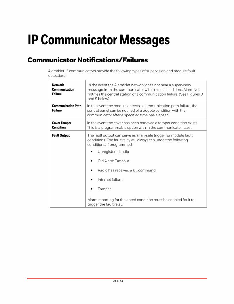
AlarmNet-i® communicators provide the following types of supervision and module fault
detection:
Network Communication Failure
In the event the AlarmNet network does not hear a supervisory
message from the communicator within a specified time, AlarmNet
notifies the central station of a communication failure. (See Figures 8
and 9 below)
Communication Path Failure
In the event the module detects a communication path failure, the
control panel can be notified of a trouble condition with the
communicator after a specified time has elapsed.
Cover Tamper Condition
In the event the cover has been removed a tamper condition exists.
This is a programmable option with in the communicator itself.
Fault Output The fault output can serve as a fail-safe trigger for module fault
conditions. The fault relay will always trip under the following
conditions, if programmed:
• Unregistered radio
• Old Alarm Timeout
• Radio has received a kill command
• Internet failure
• Tamper
Alarm reporting for the noted condition must be enabled for it to
trigger the fault relay.

PAGE 15
Device Communication Failures
1 OFF
4 MAX
7 INSTANT
READY
2 AWAY
5 TEST
8 CODE
0
3 STAY
6 BYPASS
9 CHIME
#
ARMED
READY
Check 103 LngRng
Radio 0000
I 08:47:40 02/26/16 01 0000 5555 5555 9I 08:48:44 02/12/16 01 0000 5555 5555 9S 08:49:59 02/12/16 01 RCVB 5155 5555 7I 08:49:19 02/12/16 01 0000 5555 5555 9
S 08:52:58 02/12/16 01 RCVB 5551 5555 7
I 08:53:23 02/26/16 01 0011 18 R441 01 U002
I 08:54:00 02/26/16 01 0011 18 R441 01 U002
I 08:46:20 02/26/16 01 0011 18 E401 01 U002
Fri 02/12/16 8:56 AMAuto
Central Station Receiver (AlarmNet Only)
No New Alarms
System OKAutomation OKAlarmNet OK
TestSilence AlertDisplay Next
Setup
ALARMNET-I CENTRAL
STATION RECEIVER
ALARMNET SERVER
PROTECTED PREMISES BY AN
ALARMNET-I COMMUNICATOR AlarmNetWP-003-V2
Message to Central Station
stating the server did not
receive the supervisory signal within
the programmed time period.
Network Communication Path
Failure displays on the control’s
keypad (if programmed).
Internet LTE Com
mu
nica
tion
Fa
il
Internet
Communication FailureSupervision M
essage
Supervis
ion
Figure 6: Network Com. Failure
Central Station Failures
I 08:47:40 02/26/16 01 0000 5555 5555 9I 08:48:44 02/12/16 01 0000 5555 5555 9S 08:49:59 02/12/16 01 RCVB 5155 5555 7I 08:49:19 02/12/16 01 0000 5555 5555 9
S 08:52:58 02/12/16 01 RCVB 5551 5555 7
I 08:53:23 02/26/16 01 0011 18 R441 01 U002
I 08:54:00 02/26/16 01 0011 18 R441 01 U002
I 08:46:20 02/26/16 01 0011 18 E401 01 U002
Fri 02/12/16 8:56 AMAuto
Central Station Receiver (AlarmNet Only)
No New Alarms
System OKAutomation OKAlarmNet OK
TestSilence AlertDisplay Next
Setup
ALARMNET-I CENTRAL STATION RECEIVER
ALARMNET SERVER
AlarmNetWP-004-V1
Message to Central Station
stating the server did not
receive the supervisory signal within
the programmed time period.
Typical Supervision Message
CENTRALSTATION
Internet
Internet
Figure 7: Central Station Com. Failure

PAGE 16
LTE Cellular Platform
Introduction
Resideo is focused on providing leading edge communication solutions for the security
industry. Alternative communication methods are critical in the marketplace due to VoIP
migration from POTS. The growth of broadband use in homes and businesses has increased
the viability of Internet communications for security. In addition, digital radio networks are the
future of cellular communications.
Resideo offers LTE (Long Term Evolution) cellular technologies. The LTE-A devices have
fall-back logic to GSM (Global System for Mobile) and the LTE-V communicators have
fall-back logic to CDMA Code Division Multiple Access). Supporting multiple radio
technologies and network operators allows Resideo to achieve a nearly ubiquitous coverage.
LTE, GPRS, EDGE, ECDMA and 1XRTT Data Connect Service
These cellular data services are the primary method for wirelessly sending Alarm and
Supervisory messages.
Secondary uses for the data service include connection oriented functions such as
upload/download (Compass Connect), device management and configuration (AlarmNet360),
and real time remote control functions (Total Connect).
AlarmNet® connects to the data network via several APNs (Access Point Names). These APNs
define how devices connect. AlarmNet uses APNs that connect via three methods to the
AlarmNet Network Operations Center (NOC). Two private APNs allow connection over
Multiprotocol Switching (MPLS) circuits with Virtual Private Network (VPN) backup to our carrier
NOC’s. A third reports to a VPN connection, which can be used to support disaster recovery in
the event of a loss of connectivity on the Private APN’s.
Short Messaging Service (SMS)
The SMS service serves as the backup for alarm delivery in the event the connected data network
fails. SMS delivery times are not deterministic in nature and are not as reliable as the data
network for alarm delivery. That said, the data network services operate independent of SMS
service, which means that the data network could be down while SMS is still functional. If the
data network is down, alarm and optionally, supervision functions will be sent on SMS.
SMS is also used to reach out to devices, via “shoulder tapping” to initiate a connection via the
data network for upload/download using Compass software, remote control using Resideo
Total Connect™ Remote Services and other session functions.

PAGE 17
Cellular Communications
Cellular Based
Cellular based communications operate as follows:
1. Cellular devices use the existing cellular carrier’s backbone(s) to send the signals from the
device to custom APNs (at the carriers control center)
2. Signals are sent to the AlarmNet NCC
3. An ACK is returned to the device in the field to indicate the signal was received.
ALARMNETSERVER
CARRIER’S CONTROLCENTER
CARRIER’STOWER
PROTECTEDPREMISES
Ala
rmN
etW
P-0
05
-V1
Acknowledgement returned to field
device.
Figure 8: LTE Communication Path
Remote Services Communications
1. Device (phone, tablet, pc, etc.) command or request to the Data Server
2. An SMS shoulder tap is sent to the communicator over the cellular network
3. The cellular communicator initiates contact with the Resideo Redir servers
4. Resideo Redir Server directs the control (i.e. arm, disarm, status request, etc.) to the
appropriate server. (Total Connect™, Compass Connect, Video Services, etc.)
5. Control initiates an outbound communication to the Data Server
6. A session is setup to receive the updates

PAGE 18
NOTES

PAGE 19
NOTES

2 Corporate Center Drive, Suite 100 P.O. Box 9040, Melville, NY 11747
Copyright 2019 Resideo Technologies, Inc.
www.resideo.com
Ê800-22565V1QŠ 800-22565V1 4/19 Rev. A