DE LEISTUNGSERKLÄRUNG - Hilti Deutschland · the area of the post-installed rebar connection with...
62
DoP_de_01-01_000000002192_HIT-RE 500 V3.docx LEISTUNGSERKLÄRUNG Nr. Hilti HIT-RE 500 V3 1343-CPR-M 500-22/07.14 1. Eindeutiger Kenncode des Produkttyps: Injektionssystem Hilti HIT-RE 500 V3 für Bewehrungsanschlüsse 2. Verwendungszweck(e): Produkt Verwendungszweck(e): System für nachträglich eingemörtelten Bewehrungsanschluss Zur Verankerung und/oder Unterstützung von Bauteilen in Beton (die zur Stabilität des Bauwerks beitragen) oder schwerer Bauteile, siehe Anhang, besonders Anhänge B1 bis B18 3. Hersteller: Hilti Aktiengesellschaft, Feldkircherstrasse 100, FL-9494 Schaan, Fürstentum Liechtenstein 4. Bevollmächtigter: - 5. System oder Systeme zur Bewertung und Überprüfung der Leistungsbeständigkeit: System 1 6a. Harmonisierte Norm: - Notifizierte Stelle: - 6b. Europäisches Bewertungsdokument: EAD 330087-00-0601 Europäische Technische Bewertung: ETA-16/0142 (07.11.2016) Technische Bewertungsstelle: CSTB Notifizierte Stelle(n): 1343 – MPA Darmstadt 7. Erklärte Leistungen: Mechanische Festigkeit und Standsicherheit (BWR 1) Wesentliches Merkmal Leistung Erhöhungsfaktor lb , Verbund-Effizienzfaktor k b , Bemessungsverbundspannung f bd . Siehe Anhang, besonders Anhänge C1 bis C3 Brandschutz (BWR 2) Wesentliches Merkmal Leistung Brandverhalten Die Verankerung erfüllt die Anforderungen der Klasse A1 Feuerwiderstand Siehe Anhang C3 8. Die Leistung des vorstehenden Produkts entspricht der erklärten Leistung/den erklärten Leistungen. Für die Erstellung der Leistungserklärung im Einklang mit der Verordnung (EU) Nr. 305/2011 ist allein der obengenannte Hersteller verantwortlich. DE
Transcript of DE LEISTUNGSERKLÄRUNG - Hilti Deutschland · the area of the post-installed rebar connection with...

DoP_de_01-01_000000002192_HIT-RE 500 V3.docx
LEISTUNGSERKLÄRUNG
Nr. Hilti HIT-RE 500 V3 1343-CPR-M 500-22/07.14
1. Eindeutiger Kenncode des Produkttyps:
Injektionssystem Hilti HIT-RE 500 V3 für Bewehrungsanschlüsse
2. Verwendungszweck(e):
Produkt Verwendungszweck(e):
System für nachträglich eingemörtelten Bewehrungsanschluss
Zur Verankerung und/oder Unterstützung von Bauteilen in
Beton (die zur Stabilität des Bauwerks beitragen) oder schwerer
Bauteile, siehe Anhang, besonders Anhänge B1 bis B18
3. Hersteller:
Hilti Aktiengesellschaft, Feldkircherstrasse 100, FL-9494 Schaan, Fürstentum Liechtenstein
4. Bevollmächtigter: -
5. System oder Systeme zur Bewertung und Überprüfung der Leistungsbeständigkeit:
System 1
6a. Harmonisierte Norm: -
Notifizierte Stelle: -
6b. Europäisches Bewertungsdokument: EAD 330087-00-0601
Europäische Technische Bewertung: ETA-16/0142 (07.11.2016)
Technische Bewertungsstelle: CSTB
Notifizierte Stelle(n): 1343 – MPA Darmstadt
7. Erklärte Leistungen:
Mechanische Festigkeit und Standsicherheit (BWR 1)
Wesentliches Merkmal Leistung
Erhöhungsfaktor lb, Verbund-Effizienzfaktor kb,
Bemessungsverbundspannung fbd. Siehe Anhang, besonders Anhänge C1 bis C3
Brandschutz (BWR 2)
Wesentliches Merkmal Leistung
Brandverhalten Die Verankerung erfüllt die Anforderungen der Klasse A1
Feuerwiderstand Siehe Anhang C3
8. Die Leistung des vorstehenden Produkts entspricht der erklärten Leistung/den erklärten Leistungen. Für die
Erstellung der Leistungserklärung im Einklang mit der Verordnung (EU) Nr. 305/2011 ist allein der obengenannte
Hersteller verantwortlich.
DE
DoP_de_01-01_000000002192_HIT-RE 500 V3.docx
Unterzeichnet für den Hersteller und im Namen des Herstellers von:
Hilti AG
Schaan, den 22.02.2017
Raimund Zaggl Leiter Geschäftsfeld Geschäftsfeld Anker-/Dübeltechnik
Seppo Perämäki Leiter Qualitätssicherung Geschäftsfeld Anker-/Dübeltechnik
DoP_de_01-01_000000002192_HIT-RE 500 V3.docx
LEISTUNGSERKLÄRUNG
Nr. Hilti HIT-RE 500 V3 1343-CPR-M 500-23/07.14
1. Eindeutiger Kenncode des Produkttyps:
Injektionssystem Hilti HIT-RE 500 V3
2. Verwendungszweck(e):
Produkt Verwendungszweck(e):
Metalldübel zur Verwendung in Beton
Zur Verankerung und/oder Unterstützung von Bauteilen in
Beton (die zur Stabilität des Bauwerks beitragen) oder schwerer
Bauteile, siehe Anhang, besonders Anhänge B1 bis B16
3. Hersteller:
Hilti Aktiengesellschaft, Feldkircherstrasse 100, FL-9494 Schaan, Fürstentum Liechtenstein
4. Bevollmächtigter: -
5. System oder Systeme zur Bewertung und Überprüfung der Leistungsbeständigkeit:
System 1
6a. Harmonisierte Norm: -
Notifizierte Stelle: -
6b. Europäisches Bewertungsdokument: ETAG 001, Ausgabe April 2013, verwendet als EAD
Europäische Technische Bewertung: ETA-16/0143 (30.11.2016)
Technische Bewertungsstelle: CSTB
Notifizierte Stelle(n): 1343 – MPA Darmstadt
7. Erklärte Leistungen:
Mechanische Festigkeit und Standsicherheit (BWR 1)
Wesentliches Merkmal Leistung
Charakteristischer Widerstand für statische und quasi-statische
Einwirkungen, Verschiebungen Siehe Anhang, besonders Anhänge C1 bis C16
Charakteristischer Widerstand für die seismische
Leistungskategorie C1, Verschiebungen Siehe Anhang, besonders Anhänge C17 bis C20
Charakteristischer Widerstand für die seismische
Leistungskategorie C2, Verschiebungen Siehe Anhang, besonders Anhang C21
Brandschutz (BWR 2)
Wesentliches Merkmal Leistung
Brandverhalten Die Verankerung erfüllt die Anforderungen der Klasse A1
Feuerwiderstand Keine Leistung festgestellt
8. Die Leistung des vorstehenden Produkts entspricht der erklärten Leistung/den erklärten Leistungen. Für die
Erstellung der Leistungserklärung im Einklang mit der Verordnung (EU) Nr. 305/2011 ist allein der obengenannte
Hersteller verantwortlich.
DE

DoP_de_01-01_000000002192_HIT-RE 500 V3.docx
Unterzeichnet für den Hersteller und im Namen des Herstellers von:
Hilti AG
Schaan, den 22.02.2017
Raimund Zaggl Leiter Geschäftsfeld Geschäftsfeld Anker-/Dübeltechnik
Seppo Perämäki Leiter Qualitätssicherung Geschäftsfeld Anker-/Dübeltechnik

European technical assessment ETA-1 6 / 0 1 4 2 English translation prepared by CSTB
Page 9 sur 29 |0 7 / 1 1 / 2 0 1 6
Injection system Hilti HIT-RE 500 V3
Annex B1 Intended Use Specifications.
Specifications of intended use
Anchorages subject to:
Static and quasi static loading.
Fire exposure.
Base material:
Reinforced or unreinforced normal weight concrete according to EN 206.
Strength classes C12/15 to C50/60 according to EN 206.
Maximum chloride content of 0,40 % (CL 0.40) related to the cement content according to EN 206-1.
Non-carbonated concrete.
Note: In case of a carbonated surface of the existing concrete structure the carbonated layer shall be removed in the area of the post-installed rebar connection with a diameter of ϕ + 60 mm prior to the installation of the new rebar. The depth of concrete to be removed shall correspond to at least the minimum concrete cover in accordance with EN 1992-1-1.The foregoing may be neglected if building components are new and not carbonated and if building components are in dry conditions.
Temperature in the base material:
at installation
-5 °C to +40 °C
in-service
-40 °C to +80 °C (max. long term temperature +50 °C and max. short term temperature +80 °C)
Design:
Anchorages are designed under the responsibility of an engineer experienced in anchorages and concrete work.
Verifiable calculation notes and drawings are prepared taking account of the forces to be transmitted.
Design under static or quasi-static loading in accordance with EN 1992-1-1, Annex B2 and Annex B4.
The actual position of the reinforcement in the existing structure shall be determined on the basis of the construction documentation and taken into account when designing.
Installation:
Use category: dry or wet concrete (not in flooded holes). .
Drilling technique:
hammer drilling (HD), hammer drilling with Hilti hollow drill bit TE-CD, TE-YD (HDB), compressed air drilling (CA) diamond coring, wet (DD), diamond coring, dry (PCC), diamond coring with roughening with Hilti roughening tool TE-YRT (RT).
Overhead installation is admissible.
Rebar installation carried out by appropriately qualified personnel and under the supervision of the person responsible for technical matters of the site.
Check the position of the existing rebars (if the position of existing rebars is not known, it shall be determined using a rebar detector suitable for this purpose as well as on the basis of the construction documentation and then marked on the building component for the overlap joint).
EXCERPT

European technical assessment ETA-1 6 / 0 1 4 2 English translation prepared by CSTB
Page 10 sur 29 |0 7 / 1 1 / 2 0 1 6
Injection system Hilti HIT-RE 500 V3
Annex B2 Intended Use General construction rules for post-installed rebars.
Figure B1: General construction rules for post-installed rebars
Post-installed rebar may be designed for tension forces only.
The transfer of shear forces between new concrete and existing structure shall be designed additionally according to EN 1992-1-1.
The joints for concreting must be roughened to at least such an extent that aggregate protrudes.
*) If the clear distance between lapped bars exceeds 4 · ϕ, then the lap length shall be increased by the
difference between the clear bar distance and 4 ·ϕ.
c concrete cover of post-installed rebar
c1 concrete cover at end-face of existing rebar
cmin minimum concrete cover according to Table B3 and to EN 1992-1-1
ϕ diameter of reinforcement bar
l0 lap length, according to EN 1992-1-1
lv effective embedment depth ≥ l0 + c1
d0 nominal drill bit diameter, see Annex B4
8 mm ≤ ϕ ≤ 25 mm

European technical assessment ETA-1 6 / 0 1 4 2 English translation prepared by CSTB
Page 11 sur 29 |0 7 / 1 1 / 2 0 1 6
Injection system Hilti HIT-RE 500 V3
Annex B3 Product description
Installed condition: dimensions for HZA / HZA-R.
Table B1: Hilti tension anchor HZA-R, dimensions
1) For larger clearance hole see “TR 029 section 1.1”.
Table B2: Hilti tension anchor HZA, dimensions
1) For larger clearance hole see “TR 029 section 1.1”.
Hilti Tension Anchor HZA / HZA-R
l
Hilti tension anchor HZA-R M12 M16 M20 M24
Rebar diameter [mm] 12 16 20 25
Nominal embedment depth and drill hole depth
le,ges [mm] 170 to 800 180 to 1300 190 to 1300 200 to 1300
Effective embedment depth (lv = le,ges – le)
lv [mm] le,ges – 100
Length of smooth shaft le [mm] 100
Maximum diameter of clearance hole in the fixture 1)
df [mm] 14 18 22 26
Maximum torque moment Tmax [Nm] 40 80 150 200
Hilti tension anchor HZA M12 M16 M20 M24 M27
Rebar diameter [mm] 12 16 20 25 28
Nominal embedment depth and drill hole depth
le,ges [mm] 90 to 800 100 to 1300
110 to 1300
120 to 1300
140 to 1300
Effective embedment depth (lv = le,ges – le)
lv [mm] le,ges – 20
Length of smooth shaft le [mm] 20
Nominal diameter of drill bit d0 [mm] 16 20 25 32 35
Maximum diameter of clearance hole in the fixture 1)
df [mm] 14 18 22 26 30
Maximum torque moment Tmax [Nm] 40 80 150 200 270
Marking: embossing “HZA-R” M .. / tfix
le tfix
le,ges
HZA-R M
l0 = lv

European technical assessment ETA-1 6 / 0 1 4 2 English translation prepared by CSTB
Page 12 sur 29 |0 7 / 1 1 / 2 0 1 6
Injection system Hilti HIT-RE 500 V3
Annex B4 Product description. General construction rules for HZA / HZA-R.
Figure B2: General construction rules for Hilti tension anchor HZA / HZA-R
Hilti tension anchor HZA / HZA-R may be designed for tension forces only.
The tension forces must be transferred via an overlap joint to the reinforcement in the existing structure.
The length of the bonded-in smooth shaft may not be accounted as anchorage.
The transfer of shear forces shall be ensured by appropriate additional measures, e.g. by shear lugs or by anchors with a European technical assessment (ETA).
In the anchor plate the holes for the Hilti tension anchor shall be executed as elongated holes with the axis in the direction of the shear force.
*) If the clear distance between lapped bars exceeds 4 · ϕ, then the lap length shall be increased by the
difference between the clear bar distance and 4 ·ϕ.
c concrete cover of Hilti tension anchor HZA / HZA-R
c1 concrete cover at end-face of existing rebar
cmin minimum concrete cover according to Table B3 and to EN 1992-1-1
ϕ diameter of reinforcement bar
l0 lap length, according to EN 1992-1-1
lv effective embedment depth,
le length of the smooth shaft or the bonded-in threaded part
le,ges overall embedment depth
d0 nominal drill bit diameter
European technical assessment ETA-1 6 / 0 1 4 2 English translation prepared by CSTB
Page 13 sur 29 |0 7 / 1 1 / 2 0 1 6
Injection system Hilti HIT-RE 500 V3
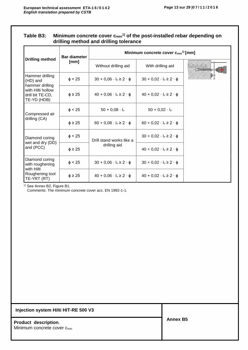
Annex B5 Product description. Minimum concrete cover cmin
Table B3: Minimum concrete cover cmin1) of the post-installed rebar depending on
drilling method and drilling tolerance
1) See Annex B2, Figure B1. Comments: The minimum concrete cover acc. EN 1992-1-1.
Drilling method Bar diameter
[mm]
Minimum concrete cover cmin1) [mm]
Without drilling aid With drilling aid
Hammer drilling (HD) and hammer drilling with Hilti hollow drill bit TE-CD, TE-YD (HDB)
ϕ < 25 30 + 0,06 · lv ≥ 2 · ϕ 30 + 0,02 · lv ≥ 2 · ϕ
ϕ ≥ 25 40 + 0,06 · lv ≥ 2 · ϕ 40 + 0,02 · lv ≥ 2 · ϕ
Compressed air drilling (CA)
ϕ < 25 50 + 0,08 · lv 50 + 0,02 · lv
ϕ ≥ 25 60 + 0,08 · lv ≥ 2 · ϕ 60 + 0,02 · lv ≥ 2 · ϕ
Diamond coring wet and dry (DD) and (PCC)
ϕ < 25 Drill stand works like a
drilling aid
30 + 0,02 · lv ≥ 2 · ϕ
ϕ ≥ 25 40 + 0,02 · lv ≥ 2 · ϕ
Diamond coring with roughening with Hilti Roughening tool TE-YRT (RT)
ϕ < 25 30 + 0,06 · lv ≥ 2 · ϕ 30 + 0,02 · lv ≥ 2 · ϕ
ϕ ≥ 25 40 + 0,06 · lv ≥ 2 · ϕ 40 + 0,02 · lv ≥ 2 · ϕ

European technical assessment ETA-1 6 / 0 1 4 2 English translation prepared by CSTB
Page 14 sur 29 |0 7 / 1 1 / 2 0 1 6
Injection system Hilti HIT-RE 500 V3
Annex B6 Product description. Maximum installation length
Table B4: Maximum embedment depth lv,max depending on bar diameter and dispenser
Elements Dispensers
rebar
Hilti Tension anchor
HDM 330, HDM 500 HDE 500 HIT-P8000D
size size lv,max [mm] lv,max [mm] lv,max [mm]
8 -
1000
1000 -
10 - 1000 -
12 HZA(-R) M12 1200 1200
14 - 1400 1400
16 HZA(-R) M16 1600 1600
18 - 700 1800 1800
20 HZA(-R) M20 600 2000 2000
22 - 500 1800 2200
24 - 300 1300 2400
25 HZA(-R) M24 300 1500 2500
26 - 300 1000 2600
28 HZA M27 300 1000 2800
30 -
-
1000 3000
32 - 700
3200 34 - 600
36 - 600
40 - 400

European technical assessment ETA-1 6 / 0 1 4 2 English translation prepared by CSTB
Page 15 sur 29 |0 7 / 1 1 / 2 0 1 6
Injection system Hilti HIT-RE 500 V3
Annex B7 Product description. Dimension: Roughening tool TE-YRT Maximum working time and minimum curing time.
Table B5: Parameters for use of the Hilti Roughening tool TE-YRT
Hilti Roughening tool TE-YRT and wear gauge RTG
Table B6: Maximum working time and minimum curing time1)
1) The curing time data are valid for dry base material only. In wet base material the curing times must be doubled.
Associated components Installation
Diamond coring Roughening tool
TE-YRT Wear gauge
RTG… Minimum roughening time
troughen
d0 [mm] d0 [mm] size troughen [sec] = hef [mm] / 10
nominal measured
18 17,9 to 18,2 18 18 hef [mm]
troughen [sec]
0 to 100 10
101 to 200 20
201 to 300 30
301 to 400 40
401 to 500 50
501 to 600 60
20 19,9 to 20,2 20 20
22 21,9 to 22,2 22 22
25 24,9 to 25,2 25 25
28 27,9 to 28,2 28 28
30 29,9 to 30,2 30 30
32 31,9 to 32,2 32 32
35 34,9 to 35,2 35 35
TE-YRT
RTG
Delivered with each TE-YRT
Temperature in the base material
T
Maximum working time twork
Initial curing time tcure,ini
Minimum curing time tcure
-5 °C to -1 °C 2 hours 48 hours 168 hours
0 °C to 4 °C 2 hours 24 hours 48 hours
5 °C to 9 °C 2 hours 16 hours 24 hours
10 °C to 14 °C 1,5 hours 12 hours 16 hours
15 °C to 19 °C 1 hour 8 hours 16 hours
20 °C to 24 °C 30 min 4 hours 7 hours
25 °C to 29 °C 20 min 3,5 hours 6 hours
30 °C to 34 °C 15 min 3 hours 5 hours
35 °C to 39 °C 12 min 2 hours 4,5 hours
40 °C 10 min 2 hours 4 hours

European technical assessment ETA-1 6 / 0 1 4 2 English translation prepared by CSTB
Page 16 sur 29 |0 7 / 1 1 / 2 0 1 6
Injection system Hilti HIT-RE 500 V3
Annex B8 Product description. Setting tools for hammer drilling and compressed air drilling
Table B7: Parameters of drilling, cleaning and setting tools, Hammer drilling and compressed air drilling
1) Assemble extension HIT-VL 16/0,7 with coupler HIT-VL K for deeper boreholes.
Elements Drill and clean Installation
Rebar / Hilti Tension Anchor
Hammer drilling (HD)
Compressed air drilling
(CA)
Brush HIT-RB
Air nozzle HIT-DL
Extension for air nozzle
Piston plug HIT-SZ
Extension for piston
plug
Maximum embedment
depth
1) -
size d0 [mm] d0 [mm] size size [-] size [-] lv,max [mm]
8 10 - 10 10
HIT-DL 10/0,8
or HIT-DL V10/1
- HIT-VL 9/1,0
250
12 - 12 12 12 1000
10 12 - 12 12 12 250
14 - 14 14 14
HIT-VL 11/1,0
1000
12 / HZA(-R) M12
14 - 14 14 14 250
16 - 16 16 16 1200
- 17 18 16 16
14 18 - 18 18 18
1400 - 17 18 16 16
16 / HZA(-R) M16
20 20 20 20
HIT-DL 16/0,8
or HIT-DL B
and/or HIT-VL 16/0,7
and/or HIT-VL 16
20
HIT-VL 16/0,7 and/or
HIT-VL 16
1600
18 22 22 22 22 22 1800
20 / HZA(-R) M20
25 - 25 25 25 2000
- 26 28 25 25
22 28 28 28 28 28 2200
24 30 30 30 30 30 500
32 32 32 32 32 2400
25 / HZA(-R) M24
30 30 30 30 30 500
32 32 32 32 32 2500
26 35 35 35 32 35 2600
28 / HZA M27
35 35 35 32 35 2800
30 - 35 35 32 35
3000 37 37 37 32 37
32 40 40 40 32 40 3200
34 - 42 42 32 42
3200 45 - 45 32 45
36 45 45 45 32 45 3200
40 55 - 55 32 55
3200 - 57 55 32 55
European technical assessment ETA-1 6 / 0 1 4 2 English translation prepared by CSTB
Page 17 sur 29 |0 7 / 1 1 / 2 0 1 6
Injection system Hilti HIT-RE 500 V3
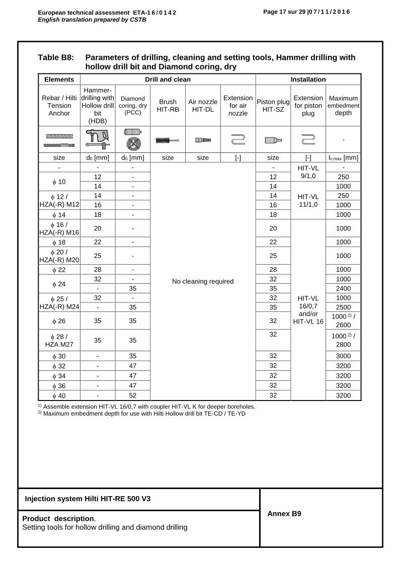
Annex B9 Product description. Setting tools for hollow drilling and diamond drilling
Table B8: Parameters of drilling, cleaning and setting tools, Hammer drilling with hollow drill bit and Diamond coring, dry
1) Assemble extension HIT-VL 16/0,7 with coupler HIT-VL K for deeper boreholes. 2) Maximum embedment depth for use with Hilti Hollow drill bit TE-CD / TE-YD
Elements Drill and clean Installation
Rebar / Hilti Tension Anchor
Hammer-drilling with Hollow drill
bit (HDB)
Diamond coring, dry
(PCC)
Brush HIT-RB
Air nozzle HIT-DL
Extension for air nozzle
Piston plug HIT-SZ
Extension for piston
plug
Maximum embedment
depth
-
size d0 [mm] d0 [mm] size size [-] size [-] lv,max [mm]
- -
No cleaning required
- HIT-VL 9/1,0
-
10 12 - 12 250
14 - 14
HIT-VL 11/1,0
1000
12 / HZA(-R) M12
14 - 14 250
16 - 16 1000
14 18 - 18 1000
16 / HZA(-R) M16
20 - 20
HIT-VL 16/0,7 and/or
HIT-VL 16
1000
18 22 - 22 1000
20 / HZA(-R) M20
25 - 25 1000
22 28 - 28 1000
24 32 - 32 1000
- 35 35 2400
25 / HZA(-R) M24
32 - 32 1000
- 35 35 2500
26 35 35 32 1000 2) /
2600
28 / HZA M27
35 35 32 1000 2) /
2800
30 - 35 32 3000
32 - 47 32 3200
34 - 47 32 3200
36 - 47 32 3200
40 - 52 32 3200

European technical assessment ETA-1 6 / 0 1 4 2 English translation prepared by CSTB
Page 18 sur 29 |0 7 / 1 1 / 2 0 1 6
Injection system Hilti HIT-RE 500 V3
Annex B10 Product description. Setting tools for diamond drilling and roughening tool
Table B9: Parameters of drilling, cleaning and setting tools, Diamond coring, wet and Diamond coring with roughening
1) Assemble extension HIT-VL 16/0,7 with coupler HIT-VL K for deeper boreholes. 2) Maximum embedment depth for use with Hilti Roughening tool TE-YRT
Elements Drill and clean Installation
Rebar / Hilti Tension Anchor
Diamond coring, wet
(DD)
Diamond coring with roughening
(RT)
Brush HIT-RB
Air nozzle HIT-DL
Extension for air nozzle
Piston plug
HIT-SZ
Extension for piston
plug
Maximum embedment
depth
-
size d0 [mm] d0 [mm] size size [-] size [-] lv,max [mm]
8 10 - 10 10
HIT-DL 10/0,8
or HIT-DL V10/1
- HIT-VL 9/1,0
250
12 - 12 12 12 1000
10 12 - 12 12 12 250
14 - 14 14 14
HIT-VL 11/1,0
1000
12 / HZA(-R) M12
14 - 14 14 14 250
16 - 16 16 16 1200
14 18 18 18 18 18 1400 / 900 2)
16 / HZA(-R) M16
20 20 20 20
HIT-DL 16/0,8
or HIT-DL B
and/or HIT-VL 16/0,7 and/or
HIT-VL 16
20
HIT-VL 16/0,7 and/or
HIT-VL 16
1600 / 1000 2)
18 22 22 22 22 22 1800 / 1200 2)
20 / HZA(-R) M20
25 25 25 25 25 2000 / 1300 2)
22 28 28 28 28 28 2200 / 1400 2)
24
30 30 30 30 30 500
32 32 32 32 32 2400 / 1600 2)
25 / HZA(-R) M24
30 30 30 30 30 500
32 32 32 32 32 2500 / 1600 2)
26 35 35 35 32 35 2600 / 1800 2)
28 / HZA M27
35 35 35 32 35 2800 / 1800 2)
30 37 - 37 32 37 3000
32 40 - 40 32 40 3200
34 42 - 42 32 42
3200 45 - 45 32 45
36 47 - 47 32 47 3200
40 52 - 52 32 52 3200

European technical assessment ETA-1 6 / 0 1 4 2 English translation prepared by CSTB
Page 19 sur 29 |0 7 / 1 1 / 2 0 1 6
Injection system Hilti HIT-RE 500 V3
Annex B11 Product description. Parameters of cleaning and setting tools. Cleaning alternatives.
Cleaning alternatives for hammer drilling
Automatic Cleaning (AC):
Cleaning is performed during drilling with Hilti hollow drill bit TE-CD, TE-YD including vacuum cleaner.
Compressed Air Cleaning (CAC):
air nozzle with an orifice opening of minimum 3,5 mm in diameter. + brush HIT-RB
Manual Cleaning (MC):
Hilti hand pump + brush HIT-RB
for cleaning of drill holes with diameters d0 ≤ 20 mm and drill hole depths h0 ≤ 10·d.
Compressed Air without brushing (C):
air nozzle with an orifice opening of minimum 3,5 mm in diameter.
for cleaning of drill holes with diameters d0 ≤ 32 mm.

European technical assessment ETA-1 6 / 0 1 4 2 English translation prepared by CSTB
Page 20 sur 29 |0 7 / 1 1 / 2 0 1 6
Injection system Hilti HIT-RE 500 V3
Annex B12 Product description. Installation instruction
Installation instruction
Hole drilling
Before drilling remove carbonized concrete and clean contact areas (see Annex B1).
In case of aborted drill hole the drill hole shall be filled with mortar.
a) Hammer drilling
Drill hole to the required embedment depth with a hammer drill set in rotation-hammer mode or a compressed air drill using an appropriately sized carbide drill bit.
Hammer drill (HD) Compressed air drill (CA)
b) Hammer drilling with Hilti hollow drill bit TE-CD, TE-YD
Drill hole to the required embedment depth with an appropriately sized Hilti TE-CD or TE-YD hollow drill bit with Hilti vacuum attachment. This drilling system removes the dust and cleans the drill hole during drilling when used in accordance with the user’s manual. After drilling is completed, proceed to the “injection preparation” step in the installation instruction.
c) Diamond coring
Diamond coring is permissible when suitable diamond core drilling machines and the corresponding core bits are used.
d) Diamond coring with roughening with Hilti roughening tool TE-YRT
Diamond coring is permissible when suitable diamond core drilling machines and the corresponding core bits are used.
For the use in combination with Hilti roughening tool TE-YRT see parameters in Table B7.
Before roughening water needs to be removed from the borehole. Check usability of the roughening tool with the wear gauge RTG.
Roughen the borehole over the whole length to the required hef.

European technical assessment ETA-1 6 / 0 1 4 2 English translation prepared by CSTB
Page 21 sur 29 | 0 7 / 1 1 / 2 0 1 6
Injection system Hilti HIT-RE 500 V3
Annex B13 Product description. Installation instruction
Splicing applications
Measure and control concrete cover c.
cdrill = c + d0/2.
Drill parallel to surface edge and to existing rebar.
Where applicable use Hilti drilling aid HIT-BH.
Drilling aid For holes lv > 20 cm use drilling aid.
Ensure that the drill hole is parallel to the existing rebar.
Three different options can be considered:
Hilti drilling aid HIT-BH
Lath or spirit level
Visual check
Drill hole cleaning Just before setting the bar the drill hole must be free of dust and debris. Inadequate hole cleaning = poor load values.
Compressed Air Cleaning (CAC) for hammer drilled holes
For all drill hole diameters d0 and all drill hole depths h0 ≤ 20 · ϕ.
Blow 2 times from the back of the hole (if needed with nozzle extension) over the whole length with oil-free compressed air (min. 6 bar at 6 m³/h) until return air stream is free of noticeable dust.
Brush 2 times with the specified brush (see Table B9) by inserting the steel brush Hilti HIT-RB to the back of the hole (if needed with extension) in a twisting motion and removing it. The brush must produce natural resistance as it enters the drill hole (brush Ø ≥ drill hole Ø) - if not the brush is too small and must be replaced with the proper brush diameter.
Blow again with compressed air 2 times until return air stream is free of noticeable dust.

European technical assessment ETA-1 6 / 0 1 4 2 English translation prepared by CSTB
Page 22 sur 29 | 0 7 / 1 1 / 2 0 1 6
Injection system Hilti HIT-RE 500 V3
Annex B14 Product description. Installation instruction
Compressed Air Cleaning (CAC) for hammer drilled holes
For drill holes deeper than 250 mm (for ϕ 8 to ϕ 12) or deeper than 20 · ϕ (for ϕ > 12 mm)
Use the appropriate air nozzle Hilti HIT-DL (see Table B9). Blow 2 times from the back of the hole over the hole length with oil-free compressed air until return air stream is free of noticeable dust. Safety tip: Do not inhale concrete dust. Use of the dust collector Hilti HIT-DRS is recommended.
Screw the round steel brush HIT-RB in one end of the brush extension(s) HIT-RBS, so that the overall length of the brush is sufficient to reach the base of the drill hole. Attach the other end of the extension to the TE-C/TE-Y chuck. Safety tip: Start machine brushing operation slowly. Start brushing operation once the brush is inserted in the borehole.
Use the appropriate air nozzle Hilti HIT-DL (see Table B9). Blow 2 times from the back of the hole over the hole length with oil-free compressed air until return air stream is free of noticeable dust. Safety tip: Do not inhale concrete dust. Use of the dust collector Hilti HIT-DRS is recommended.
Manual Cleaning (MC) for hammer drilled holes
For drill hole diameters d0 ≤ 20 mm and all drill hole depths h0 ≤ 10 · ϕ.
The Hilti hand pump may be used for blowing out drill holes up to diameters d0 ≤ 20 mm and drill hole depths h0 ≤ 10 · ϕ.
Blow out at least 4 times from the back of the drill hole until return air stream is free of noticeable dust.
Brush 4 times with the specified brush (see Table B9) by inserting the steel brush Hilti HIT-RB to the back of the hole (if needed with extension) in a twisting motion and removing it. The brush must produce natural resistance as it enters the drill hole (brush Ø ≥ drill hole Ø) - if not the brush is too small and must be replaced with the proper brush diameter.
Blow again with the Hilti hand pump at least 4 times until return air stream is free of noticeable dust.

European technical assessment ETA-1 6 / 0 1 4 2 English translation prepared by CSTB
Page 23 sur 29 | 0 7 / 1 1 / 2 0 1 6
Injection system Hilti HIT-RE 500 V3
Annex B15 Product description. Installation instruction
Compressed Air without brushing for hammer drilled holes
For drill hole diameters d0 ≤ 32 mm
Blow 2 times from the back of the hole (if needed with nozzle extension) over the whole length with oil-free compressed air (min. 6 bar at 6 m³/h) until return air stream is free of noticeable dust.
Cleaning of diamond cored holes: For all drill hole diameters d0 and all drill hole depths h0.
Flush 2 times by inserting a water hose (water-line pressure) to the back of the hole until water runs clear.
Brush 2 times with the specified brush (see Table B11) by inserting the steel brush Hilti HIT-RB to the back of the hole (if needed with extension) in a twisting motion and removing it. The brush must produce natural resistance as it enters the drill hole (brush Ø ≥ drill hole Ø) - if not the brush is too small and must be replaced with the proper brush diameter.
Flush 2 times by inserting a water hose (water-line pressure) to the back of the hole until water runs clear.
Blow 2 times from the back of the hole (if needed with nozzle extension) over the whole length with oil-free compressed air (min. 6 bar at 6 m³/h) until return air stream is free of noticeable dust and water. For drill hole diameters ≥ 32 mm the compressor has to supply a minimum air flow of 140 m³/h.
Brush 2 times with the specified brush size (brush Ø ≥ drill hole Ø, see Table B11) by inserting the steel brush Hilti HIT-RB to the back of the hole (if needed with extension) in a twisting motion and removing it. The brush must produce natural resistance as it enters the drill hole – if not the brush is too small and must be replaced with the proper brush diameter.
Blow again with compressed air 2 times until return air stream is free of noticeable dust and water.

European technical assessment ETA-1 6 / 0 1 4 2 English translation prepared by CSTB
Page 24 sur 29 | 0 7 / 1 1 / 2 0 1 6
Injection system Hilti HIT-RE 500 V3
Annex B16 Product description. Installation instruction
Cleaning of diamond cored holes with roughening with Hilti roughening tool TE-YRT: For all drill hole diameters d0 and all drill hole depths h0.
Flush 2 times by inserting a water hose (water-line pressure) to the back of the hole until water runs clear.
Brush 2 times with the specified brush (see Table B11) by inserting the steel brush Hilti HIT-RB to the back of the hole (if needed with extension) in a twisting motion and removing it. The brush must produce natural resistance as it enters the drill hole (brush Ø ≥ drill hole Ø) - if not the brush is too small and must be replaced with the proper brush diameter.
Blow 2 times from the back of the hole (if needed with nozzle extension) over the whole length with oil-free compressed air (min. 6 bar at 6 m³/h) until return air stream is free of noticeable dust and water. For drill hole diameters ≥ 32 mm the compressor has to supply a minimum air flow of 140 m³/h.
Rebar preparation
Before use, make sure the rebar is dry and free of oil or other residue. Mark the embedment depth on the rebar (e.g. with tape) → lv. Insert Rebar in borehole to verify hole and setting depth lv.
Injection preparation
Tightly attach Hilti mixing nozzle HIT-RE-M to foil pack manifold. Do not modify the mixing nozzle. Observe the instruction for use of the dispenser. Check foil pack holder for proper function. Insert foil pack into foil pack holder and put holder into dispenser.
The foil pack opens automatically as dispensing is initiated. Depending on the size of the foil pack an initial amount of adhesive has to be discarded. Discarded quantities are: 3 strokes for 330 ml foil pack, 4 strokes for 500 ml foil pack, 65 ml for 1400 ml foil pack.
European technical assessment ETA-1 6 / 0 1 4 2 English translation prepared by CSTB
Page 25 sur 29 | 0 7 / 1 1 / 2 0 1 6
Injection system Hilti HIT-RE 500 V3
Annex B17 Product description. Installation instruction
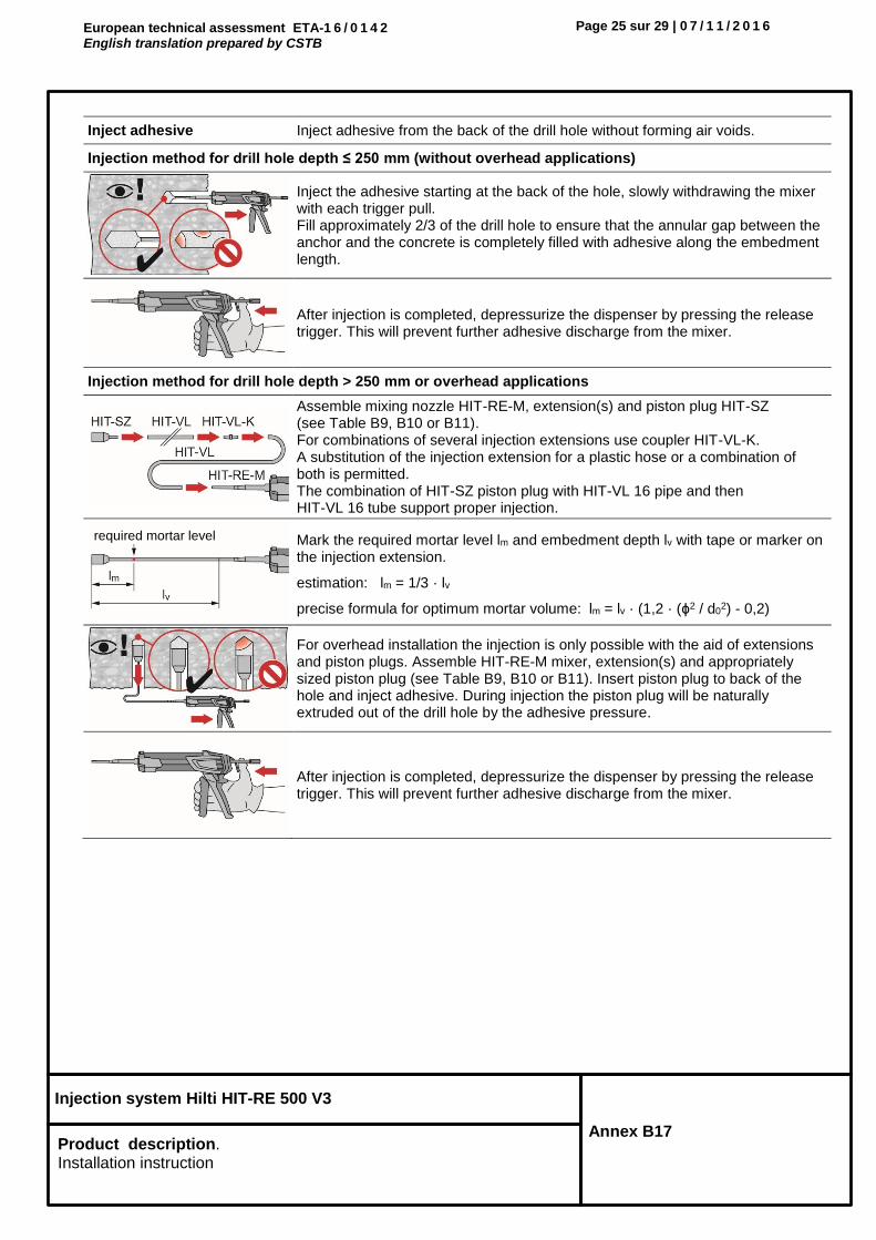
Inject adhesive Inject adhesive from the back of the drill hole without forming air voids.
Injection method for drill hole depth ≤ 250 mm (without overhead applications)
Inject the adhesive starting at the back of the hole, slowly withdrawing the mixer with each trigger pull. Fill approximately 2/3 of the drill hole to ensure that the annular gap between the anchor and the concrete is completely filled with adhesive along the embedment length.
After injection is completed, depressurize the dispenser by pressing the release trigger. This will prevent further adhesive discharge from the mixer.
Injection method for drill hole depth > 250 mm or overhead applications
Assemble mixing nozzle HIT-RE-M, extension(s) and piston plug HIT-SZ (see Table B9, B10 or B11). For combinations of several injection extensions use coupler HIT-VL-K. A substitution of the injection extension for a plastic hose or a combination of both is permitted. The combination of HIT-SZ piston plug with HIT-VL 16 pipe and then HIT-VL 16 tube support proper injection.
Mark the required mortar level lm and embedment depth lv with tape or marker on the injection extension.
estimation: lm = 1/3 · lv
precise formula for optimum mortar volume: lm = lv · (1,2 · (ϕ2 / d02) - 0,2)
For overhead installation the injection is only possible with the aid of extensions and piston plugs. Assemble HIT-RE-M mixer, extension(s) and appropriately sized piston plug (see Table B9, B10 or B11). Insert piston plug to back of the hole and inject adhesive. During injection the piston plug will be naturally extruded out of the drill hole by the adhesive pressure.
After injection is completed, depressurize the dispenser by pressing the release trigger. This will prevent further adhesive discharge from the mixer.
required mortar level

European technical assessment ETA-1 6 / 0 1 4 2 English translation prepared by CSTB
Page 26 sur 29 | 0 7 / 1 1 / 2 0 1 6
Injection system Hilti HIT-RE 500 V3
Annex B18 Product description. Installation instruction
Setting the element Before use, verify that the element is dry and free of oil and other contaminants.
For easy installation insert the rebar into the drill hole while slowly twisting until the embedment mark is at the concrete surface level.
For overhead application:
During insertion of the rebar mortar might flow out of the drill hole. For collection of the flowing mortar HIT-OHC may be used. Support the rebar and secure it from falling until mortar has started to harden, e.g. using wedges HIT-OHW.
For overhead installation use piston plugs and fix embedded parts with e.g. wedges.
After installing the rebar the annular gap must be completely filled with mortar. Proper installation: • desired anchoring embedment lv is reached: embedment mark at concrete
surface.• excess mortar flows out of the borehole after the rebar has been fully
inserted until the embedment mark.
Observe the working time twork (see Table B8), which varies according to temperature of base material. Minor adjustments to the rebar position may be performed during the working time.
Full load may be applied only after the curing time tcure has elapsed (see Table B8).
European technical assessment ETA-1 6 / 0 1 4 2 English translation prepared by CSTB
Page 27 sur 29 | 0 7 / 1 1 / 2 0 1 6
Injection system Hilti HIT-RE 500 V3
Annex C1 Performance. Minimum anchorage length and minimum lap length. Design values of ultimate bond resistance fbd.
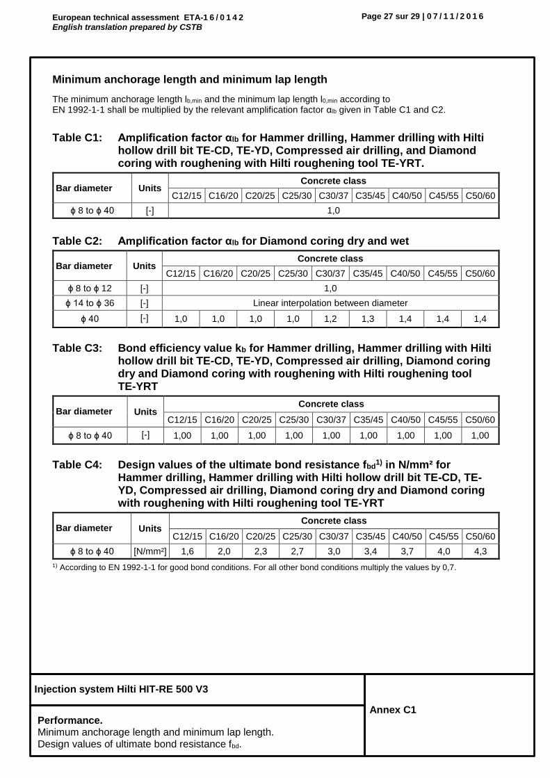
Minimum anchorage length and minimum lap length
The minimum anchorage length lb,min and the minimum lap length l0,min according to EN 1992-1-1 shall be multiplied by the relevant amplification factor αlb given in Table C1 and C2.
Table C1: Amplification factor αlb for Hammer drilling, Hammer drilling with Hilti hollow drill bit TE-CD, TE-YD, Compressed air drilling, and Diamond coring with roughening with Hilti roughening tool TE-YRT.
Bar diameter Units Concrete class
C12/15 C16/20 C20/25 C25/30 C30/37 C35/45 C40/50 C45/55 C50/60
ϕ 8 to ϕ 40 [-] 1,0
Table C2: Amplification factor αlb for Diamond coring dry and wet
Bar diameter Units Concrete class
C12/15 C16/20 C20/25 C25/30 C30/37 C35/45 C40/50 C45/55 C50/60
ϕ 8 to ϕ 12 [-] 1,0
ϕ 14 to ϕ 36 [-] Linear interpolation between diameter
ϕ 40 [-] 1,0 1,0 1,0 1,0 1,2 1,3 1,4 1,4 1,4
Table C3: Bond efficiency value kb for Hammer drilling, Hammer drilling with Hilti hollow drill bit TE-CD, TE-YD, Compressed air drilling, Diamond coring dry and Diamond coring with roughening with Hilti roughening tool TE-YRT
Bar diameter Units Concrete class
C12/15 C16/20 C20/25 C25/30 C30/37 C35/45 C40/50 C45/55 C50/60
ϕ 8 to ϕ 40 [-] 1,00 1,00 1,00 1,00 1,00 1,00 1,00 1,00 1,00
Table C4: Design values of the ultimate bond resistance fbd1) in N/mm² for
Hammer drilling, Hammer drilling with Hilti hollow drill bit TE-CD, TE-YD, Compressed air drilling, Diamond coring dry and Diamond coring with roughening with Hilti roughening tool TE-YRT
Bar diameter Units Concrete class
C12/15 C16/20 C20/25 C25/30 C30/37 C35/45 C40/50 C45/55 C50/60
ϕ 8 to ϕ 40 [N/mm²] 1,6 2,0 2,3 2,7 3,0 3,4 3,7 4,0 4,3
1) According to EN 1992-1-1 for good bond conditions. For all other bond conditions multiply the values by 0,7.

European technical assessment ETA-1 6 / 0 1 4 2 English translation prepared by CSTB
Page 28 sur 29 | 0 7 / 1 1 / 2 0 1 6
Injection system Hilti HIT-RE 500 V3
Annex C2 Performance. Minimum anchorage length and minimum lap length. Design values of ultimate bond resistance fbd.
Table C5: Bond efficiency value kb for Diamond coring wet
Bar diameter Concrete class
C12/15 C16/20 C20/25 C25/30 C30/37 C35/45 C40/50 C45/55 C50/60
8 1,00 1,00 1,00 1,00 1,00 1,00 1,00 1,00 0,99
10 1,00 1,00 1,00 1,00 1,00 1,00 1,00 1,00 0,98
12 1,00 1,00 1,00 1,00 1,00 1,00 1,00 1,00 0,97
14 1,00 1,00 1,00 1,00 1,00 1,00 1,00 0,94 0,88
16 1,00 1,00 1,00 1,00 1,00 1,00 1,00 0,93 0,87
20 1,00 1,00 1,00 1,00 1,00 1,00 0,99 0,91 0,86
25 1,00 1,00 1,00 1,00 1,00 1,00 0,97 0,89 0,84
28 1,00 1,00 1,00 1,00 1,00 1,00 0,95 0,88 0,82
30 1,00 1,00 1,00 1,00 1,00 1,00 0,94 0,87 0,82
32 1,00 1,00 1,00 1,00 1,00 1,00 0,93 0,86 0,81
36 1,00 1,00 1,00 1,00 1,00 1,00 0,92 0,85 0,79
40 1,00 1,00 1,00 1,00 1,00 0,98 0,90 0,83 0,78
Table C6: Design values of the ultimate bond resistance fbd1) in N/mm² for
Diamond coring wet
Bar diameter Concrete class
C12/15 C16/20 C20/25 C25/30 C30/37 C35/45 C40/50 C45/55 C50/60
8 1,6 2,0 2,3 2,7 3,0 3,4 3,7 4,0 4,0
10 1,6 2,0 2,3 2,7 3,0 3,4 3,7 4,0 4,0
12 1,6 2,0 2,3 2,7 3,0 3,4 3,7 4,0 4,0
14 1,6 2,0 2,3 2,7 3,0 3,4 3,7 3,7 3,7
16 1,6 2,0 2,3 2,7 3,0 3,4 3,7 3,7 3,7
20 1,6 2,0 2,3 2,7 3,0 3,4 3,4 3,4 3,4
25 1,6 2,0 2,3 2,7 3,0 3,4 3,4 3,4 3,4
28 1,6 2,0 2,3 2,7 3,0 3,4 3,4 3,4 3,4
30 1,6 2,0 2,3 2,7 3,0 3,4 3,4 3,4 3,4
32 1,6 2,0 2,3 2,7 3,0 3,4 3,4 3,4 3,4
36 1,6 2,0 2,3 2,7 3,0 3,4 3,4 3,4 3,4
40 1,6 2,0 2,3 2,7 3,0 3,0 3,0 3,0 3,0
1) According to EN 1992-1-1 for good bond conditions. For all other bond conditions multiply the values by 0,7.

European technical assessment ETA-1 6 / 0 1 4 2 English translation prepared by CSTB
Page 29 sur 29 | 0 7 / 1 1 / 2 0 1 6
Injection system Hilti HIT-RE 500 V3
Annex C3 Performance.
Temperature reduction factor kfi(θ).
Figure C1: Temperature reduction factor kfi()
The analytic equation that describe the variation of kfi() with temperature is given by the following function :
If 45°C ≤ ≤152°C: 𝑘𝑓𝑖(𝜃) =𝑓𝑏𝑚(𝜃)
𝑓𝑏𝑚,𝑟𝑞𝑑,𝑑 ≤ 1.0
If < 45°C: 𝑘𝑓𝑖(𝜃) = 1.0
If > 152°C: 𝑘𝑓𝑖(𝜃) = 0.0
With
𝑓𝑏𝑚(𝜃) = 1178,2. 𝜃−1.255 𝜃 𝑖𝑛 °𝐶
45 152

European technical assessment ETA-1 6 / 0 1 4 3 English translation prepared by CSTB
Page 8 sur 44 | 3 0 / 1 1 / 2 0 1 6
Injection system Hilti HIT-RE 500 V3
Annex B1 Intended use
Specifications.
Specifications of intended use
Anchorages subject to:
Static and quasi static loading. Seismic performance category C1 Seismic performance category C2 (only threaded rod HIT-V and AM grade 8.8 with hammer drilling and
hammer drilling with Hilti hollow drill bit TE-CD, TE-YD).
Base material:
Reinforced or unreinforced normal weight concrete according to EN 206:2013. Strength classes C20/25 to C50/60 according to EN 206:2013. Cracked and non-cracked concrete. Flooded holes for non cracked concrete only
Temperature in the base material:
At installation -5 °C to +40 °C
In-service Temperature range I: -40 °C to +40 °C
(max. long term temperature +24 °C and max. short term temperature +40 °C) Temperature range II: -40 °C to +70 °C
(max. long term temperature +43 °C and max. short term temperature +70 °C)
Use conditions (Environmental conditions):
Structures subject to dry internal conditions (zinc coated steel, stainless steel or high corrosion resistant steel).
Structures subject to external atmospheric exposure (including industrial and marine environment) and to permanently damp internal conditions, if no particular aggressive conditions exist (stainless steel or high corrosion resistant steel).
Structures subject to external atmospheric exposure and to permanently damp internal conditions, if other particular aggressive conditions exist (high corrosion resistant steel). Note: Particular aggressive conditions are e.g. permanent, alternating immersion in seawater or the splash zone of seawater, chloride atmosphere of indoor swimming pools or atmosphere with extreme chemical pollution (e.g. in desulphurization plants or road tunnels where de-icing products are used).
Design:
Anchorages are designed under the responsibility of an engineer experienced in anchorages and concrete work.
Verifiable calculation notes and drawings are prepared taking account of the loads to be anchored. The position of the anchor is indicated on the design drawings (e. g. position of the anchor relative to reinforcement or to supports, etc.).
Anchorages under static or quasi-static loading are designed in accordance with: “EOTA Technical Report TR 029, 09/2010” “CEN/TS 1992-4:2009”
Anchorages under seismic actions (cracked concrete) are designed in accordance with: “EOTA Technical Report TR 045, 02/2013” Anchorages shall be positioned outside of critical regions (e.g. plastic hinges) of the concrete structure. Fastenings in stand-off installation or with a grout layer under seismic action are not covered in this European technical assessment (ETA).
EXCERPT

European technical assessment ETA-1 6 / 0 1 4 3 English translation prepared by CSTB
Page 9 sur 44 | 3 0 / 1 1 / 2 0 1 6
Injection system Hilti HIT-RE 500 V3
Annex B2 Intended use
Specifications.
Installation:
Use category: dry or wet concrete (not in flooded holes): for all drilling techniques dry or wet concrete or installation in flooded holes: for hammer drilling only, for non-cracked
concrete only Drilling technique:
hammer drilling, hammer drilling with Hilti hollow drill bit TE-CD, TE-YD, diamond coring, diamond coring with roughening with Hilti roughening tool TE-YRT.
Overhead installation is admissible. Anchor installation carried out by appropriately qualified personnel and under the supervision of the
person responsible for technical matters of the site.
European technical assessment ETA-1 6 / 0 1 4 3 English translation prepared by CSTB
Page 10 sur 44 | 3 0 / 1 1 / 2 0 1 6
Injection system Hilti HIT-RE 500 V3
Annex B3 Intended Use
Installation parameters.
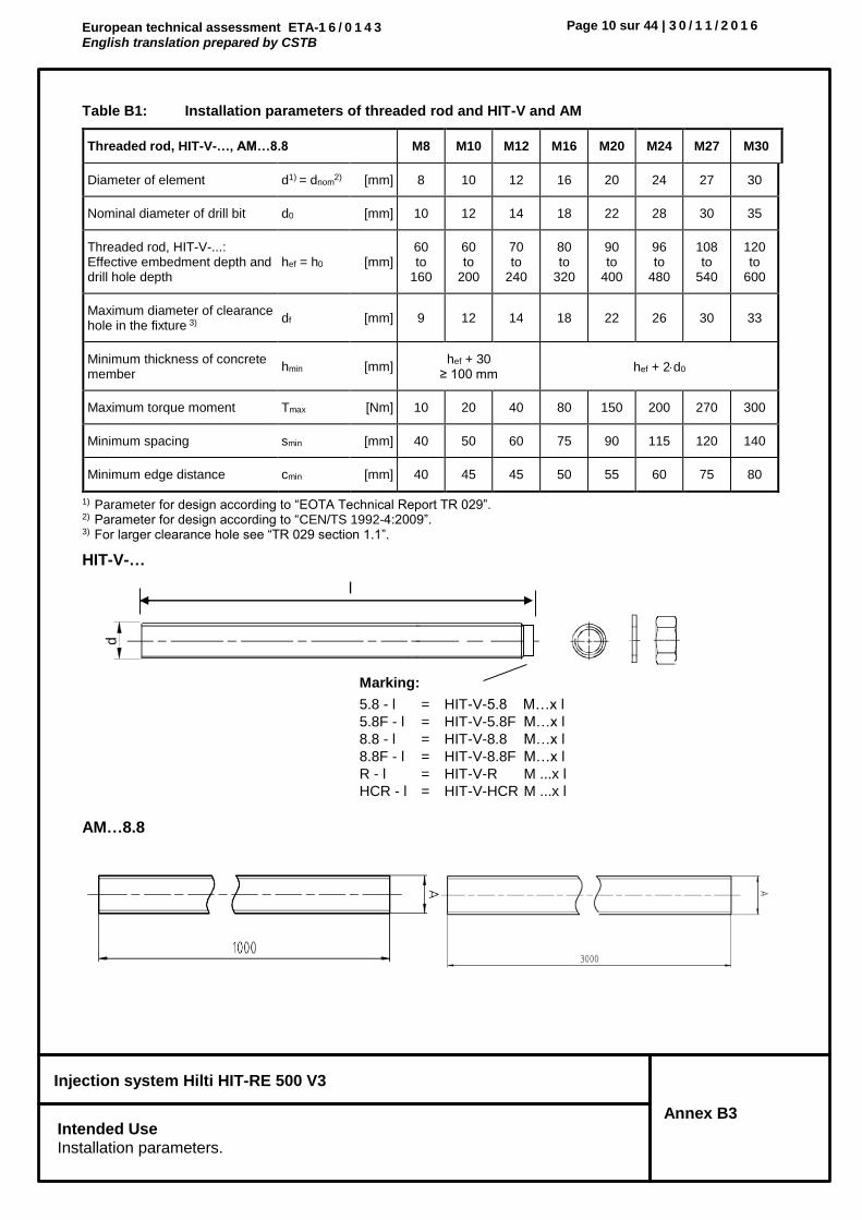
Table B1: Installation parameters of threaded rod and HIT-V and AM
1) Parameter for design according to “EOTA Technical Report TR 029”.2) Parameter for design according to “CEN/TS 1992-4:2009”.3) For larger clearance hole see “TR 029 section 1.1”.
HIT-V-…
AM…8.8
Threaded rod, HIT-V-…, AM…8.8 M8 M10 M12 M16 M20 M24 M27 M30
Diameter of element d1) = dnom2) [mm] 8 10 12 16 20 24 27 30
Nominal diameter of drill bit d0 [mm] 10 12 14 18 22 28 30 35
Threaded rod, HIT-V-...: Effective embedment depth and drill hole depth
hef = h0 [mm] 60 to
160
60 to
200
70 to
240
80 to
320
90 to
400
96 to
480
108 to
540
120 to
600
Maximum diameter of clearance hole in the fixture 3) df [mm] 9 12 14 18 22 26 30 33
Minimum thickness of concrete member
hmin [mm] hef + 30
≥ 100 mm hef + 2d0
Maximum torque moment Tmax [Nm] 10 20 40 80 150 200 270 300
Minimum spacing smin [mm] 40 50 60 75 90 115 120 140
Minimum edge distance cmin [mm] 40 45 45 50 55 60 75 80
d
Marking:
5.8 - l = HIT-V-5.8 M…x l
5.8F - l = HIT-V-5.8F M…x l
8.8 - l = HIT-V-8.8 M…x l
8.8F - l = HIT-V-8.8F M…x l
R - l = HIT-V-R M ...x l
HCR - l = HIT-V-HCR M ...x l
l

European technical assessment ETA-1 6 / 0 1 4 3 English translation prepared by CSTB
Page 11 sur 44 | 3 0 / 1 1 / 2 0 1 6
Injection system Hilti HIT-RE 500 V3
Annex B4 Intended Use Installation parameters.
Table B2: Installation parameters of internally threaded sleeve HIS-(R)N
1) Parameter for design according to “EOTA Technical Report TR 029”. 2) Parameter for design according to “CEN/TS 1992-4:2009”. 3) For larger clearance hole see “TR 029 section 1.1”.
Internally threaded sleeve HIS-(R)N…
Internally threaded sleeve HIS-(R)N M8 M10 M12 M16 M20
Outer diameter of sleeve d1) = dnom2) [mm] 12,5 16,5 20,5 25,4 27,6
Nominal diameter of drill bit d0 [mm] 14 18 22 28 32
Effective embedment depth and drill hole depth
hef = h0 [mm] 90 110 125 170 205
Maximum diameter of clearance hole in the fixture 3) df [mm] 9 12 14 18 22
Minimum thickness of concrete member
hmin [mm] 120 150 170 230 270
Maximum torque moment Tmax [Nm] 10 20 40 80 150
Thread engagement length min-max
hs [mm] 8-20 10-25 12-30 16-40 20-50
Minimum spacing smin [mm] 60 75 90 115 130
Minimum edge distance cmin [mm] 40 45 55 65 90 H
ILT
I H
IS..
.
hef
d
Marking: Identifying mark - HILTI and embossing “HIS-N” (for zinc coated steel) embossing “HIS-RN” (for stainless steel)

European technical assessment ETA-1 6 / 0 1 4 3 English translation prepared by CSTB
Page 12 sur 44 | 3 0 / 1 1 / 2 0 1 6
Injection system Hilti HIT-RE 500 V3
Annex B5 Intended Use Installation parameters.
Table B3: Installation parameters of Hilti tension anchor HZA-R
1) For larger clearance hole see “TR 029 section 1.1”.
Hilti Tension Anchor HZA-R
Hilti tension anchor HZA-R M12 M16 M20 M24
Rebar diameter [mm] 12 16 20 25
Nominal embedment depth and drill hole depth hnom = h0 [mm] 170 to
240 180 to
320 190 to
400 200 to
500
Effective embedment depth (hef = hnom – le) hef [mm] hnom – 100
Length of smooth shaft le [mm] 100
Nominal diameter of drill bit d0 [mm] 16 20 25 32
Maximum diameter of clearance hole in the fixture 1)
df [mm] 14 18 22 26
Maximum torque moment Tmax [Nm] 40 80 150 200
Minimum thickness of concrete member hmin [mm] hnom + 2·d0
Minimum spacing smin [mm] 65 80 100 130
Minimum edge distance cmin [mm] 45 50 55 60
Marking: embossing “HZA-R” M .. / tfix
le tfix
hnom
HZA-R M
hef

European technical assessment ETA-1 6 / 0 1 4 3 English translation prepared by CSTB
Page 13 sur 44 | 3 0 / 1 1 / 2 0 1 6
Injection system Hilti HIT-RE 500 V3
Annex B6 Intended Use.
Installation parameters.
Table B4: Installation parameters of Hilti tension anchor HZA
1) For larger clearance hole see “TR 029 section 1.1”.
Hilti tension anchor HZA M12 M16 M20 M24 M27
Rebar diameter [mm] 12 16 20 25 28
Nominal embedment depth and drill hole depth
hnom = h0 [mm] 90 to 240 100 to 320 110 to 400 120 to 500 140 to 560
Effective embedment depth (hef = hnom – le)
hef [mm] hnom – 20
Length of smooth shaft le [mm] 20
Nominal diameter of drill bit d0 [mm] 16 20 25 32 35
Maximum diameter of clearance hole in the fixture 1)
df [mm] 14 18 22 26 30
Maximum torque moment Tmax [Nm] 40 80 150 200 270
Minimum thickness of concrete member
hmin [mm] hnom + 2·d0
Minimum spacing smin [mm] 65 80 100 130 140
Minimum edge distance cmin [mm] 45 50 55 60 75

European technical assessment ETA-1 6 / 0 1 4 3 English translation prepared by CSTB
Page 14 sur 44 | 3 0 / 1 1 / 2 0 1 6
Injection system Hilti HIT-RE 500 V3
Annex B7 Intended Use.
Installation parameters
Table B5: Installation parameters of reinforcing bar (rebar)
1) Each of the two given values can be used.
Reinforcing bar (rebar)
For Rebar bolt
Minimum value of related rib area fR,min according to EN 1992-1-1:2004+AC:2010.
Rib height of the bar hrib shall be in the range 0,05· ≤ hrib ≤ 0,07·
(: Nominal diameter of the bar; hrib: Rib height of the bar).
Reinforcing bar (rebar) 8 10 12 14 16 20 25 28 30 32
Diameter [mm] 8 10 12 14 16 20 25 28 30 32
Effective embedment depth and drill hole depth
hef = h0
[mm] 60 to
160
60 to
200
70 to
240
75 to
280
80 to
320
90 to
400
100 to
500
112 to
560
120 to
600
128 to
640
Nominal diameter of drill bit
d0 [mm] 101) 121)
121)
141) 141) 161) 18 20 25
301)
321) 35 37 40
Minimum thickness of concrete member
hmin [mm] hef + 30
≥ 100 mm hef + 2·d0
Minimum spacing smin [mm] 40 50 60 70 80 100 125 140 150 160
Minimum edge distance cmin [mm] 40 45 45 50 50 65 70 75 80 80

European technical assessment ETA-1 6 / 0 1 4 3 English translation prepared by CSTB
Page 15 sur 44 | 3 0 / 1 1 / 2 0 1 6
Injection system Hilti HIT-RE 500 V3
Annex B8 Intended Use.
Maximum working time and minimum curing time
Table B6: Minimum curing time1)
1) The curing time data are valid for dry base material only. In wet base material the curing times must be doubled.
Temperature in the base material T
Maximum working time twork
Minimum curing time tcure
1)
-5 °C to -1 °C 2 hours 168 hours
0 °C to 4 °C 2 hours 48 hours
5 °C to 9 °C 2 hours 24 hours
10 °C to 14 °C 1,5 hours 16 hours
15 °C to 19 °C 1 hours 16 hours
20 °C to 24 °C 30 min 7 hours
25 °C to 29 °C 20 min 6 hours
30 °C to 34 °C 15 min 5 hours
35 °C to 39 °C 12 min 4,5 hours
40 °C 10 min 4 hours

European technical assessment ETA-1 6 / 0 1 4 3 English translation prepared by CSTB
Page 16 sur 44 | 3 0 / 1 1 / 2 0 1 6
Injection system Hilti HIT-RE 500 V3
Annex B9 Intended use.
Cleaning and setting tools
Table B7: Parameters of cleaning and setting tools
Cleaning alternatives
Compressed Air Cleaning (CAC):
air nozzle with an orifice opening of minimum 3,5 mm in diameter.
Automatic Cleaning (AC):
Cleaning is performed during drilling with Hilti TE-CD and TE-YD drilling system including vacuum cleaner.
Elements Drill and clean Installa-
tion
Threaded rod,
HIT-V-… AM…8.8
HIS-(R)N Rebar HZA(-R)
Hammer drilling Diamond coring
Brush Piston plug
Hollow drill bit TE-CD,
TE-YD
Roughen-ing tool TE-YRT
Size Name Size Size d0 [mm] d0 [mm] d0 [mm] d0 [mm] HIT-RB HIT-SZ
M8 - 8 - 10 - 10 - 10 -
M10 - 8, 10 - 12 - 12 - 12 12
M12 M8 10, 12 - 14 14 14 - 14 14
- - 12 M12 16 16 16 - 16 16
M16 M10 14 - 18 18 18 18 18 18
- - 16 M16 20 20 20 20 20 20
M20 M12 - - 22 22 22 22 22 22
- - 20 M20 25 25 25 25 25 25
M24 M16 - - 28 28 28 28 28 28
M27 - - - 30 - 30 30 30 30
- M20 25 M24 32 32 32 32 32 32
M30 - 28 M27 35 35 35 35 35 35
- - 30 - 37 - 37 - 37 37
- - 32 - 40 - - - 40 40
- - 42 - 42 42

European technical assessment ETA-1 6 / 0 1 4 3 English translation prepared by CSTB
Page 17 sur 44 | 3 0 / 1 1 / 2 0 1 6
Injection system Hilti HIT-RE 500 V3
Annex B10 Intended use.
Parameters for use of the Hilti Roughening tool TE-YRT
Table B8: Parameters for use of the Hilti roughening tool TE-YRT
Hilti roughening tool TE-YRT and wear gauge RTG
Associated components Installation
Diamond coring Roughening tool
TE-YRT Wear gauge
RTG… Minimum roughening time
troughen
d0 [mm] d0 [mm] size troughen [sec] = hef [mm] / 10
nominal measured
18 17,9 to 18,2 18 18
hef [mm] troughen [sec]
0 to 100 10
101 to 200 20
201 to 300 30
301 to 400 40
401 to 500 50
501 to 600 60
20 19,9 to 20,2 20 20
22 21,9 to 22,2 22 22
25 24,9 to 25,2 25 25
28 27,9 to 28,2 28 28
30 29,9 to 30,2 30 30
32 31,9 to 32,2 32 32
35 34,9 to 35,2 35 35
TE-YRT
RTG

European technical assessment ETA-1 6 / 0 1 4 3 English translation prepared by CSTB
Page 18 sur 44 | 3 0 / 1 1 / 2 0 1 6
Injection system Hilti HIT-RE 500 V3
Annex B11 Intended use.
Installation instructions
Installation instruction
Hole drilling
a) Hammer drilling: For dry or wet concrete and installation in flooded holes (no sea water).
Drill hole to the required embedment depth with a hammer drill set in rotation-hammer mode using an appropriately sized carbide drill bit.
b) Hammer drilling with Hilti hollow drill bit TE-CD, TE-YD: For dry and wet concrete only.
Drill hole to the required embedment depth with an appropriately sized Hilti TE-CD or TE-YD hollow drill bit with Hilti vacuum attachment. This drilling system removes the dust and cleans the drill hole during drilling when used in accordance with the user’s manual. After drilling is completed, proceed to the “injection preparation” step in the installation instruction.
c) Diamond coring: For dry and wet concrete only.
Diamond coring is permissible when suitable diamond core drilling machines and the corresponding core bits are used.
d) Diamond coring with roughening with Hilti roughening tool TE-YRT: For dry and wet concrete only.
Diamond coring is permissible when suitable diamond core drilling machines and the corresponding core bits are used. For the use in combination with Hilti roughening tool TE-YRT see parameters in Table B8. Before roughening water needs to be removed from the borehole. Check usability of the roughening tool with the wear gauge RTG. Roughen the borehole over the whole length to the required hef.

European technical assessment ETA-1 6 / 0 1 4 3 English translation prepared by CSTB
Page 19 sur 44 | 3 0 / 1 1 / 2 0 1 6
Injection system Hilti HIT-RE 500 V3
Annex B12 Intended use.
Installation instructions
Drill hole cleaning: Just before setting an anchor, the drill hole must be free of dust and debris. Inadequate hole cleaning = poor load values.
Compressed Air Cleaning (CAC): For all drill hole diameters d0 and all drill hole depths h0.
Blow 2 times from the back of the hole (if needed with nozzle extension) over the whole length with oil-free compressed air (min. 6 bar at 6 m³/h) until return air stream is free of noticeable dust. For drill hole diameters ≥ 32 mm the compressor has to supply a minimum air flow of 140 m³/h.
Brush 2 times with the specified brush (see Table B7) by inserting the steel brush Hilti HIT-RB to the back of the hole (if needed with extension) in a twisting motion and removing it. The brush must produce natural resistance as it enters the drill hole (brush Ø ≥ drill hole Ø) - if not the brush is too small and must be replaced with the proper brush diameter.
Blow again with compressed air 2 times until return air stream is free of noticeable dust.
European technical assessment ETA-1 6 / 0 1 4 3 English translation prepared by CSTB
Page 20 sur 44 | 3 0 / 1 1 / 2 0 1 6
Injection system Hilti HIT-RE 500 V3
Annex B13 Intended use.
Installation instructions
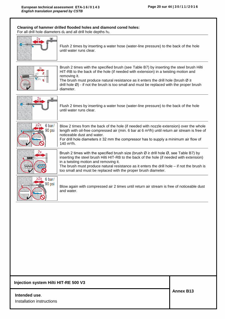
Cleaning of hammer drilled flooded holes and diamond cored holes: For all drill hole diameters d0 and all drill hole depths h0.
Flush 2 times by inserting a water hose (water-line pressure) to the back of the hole until water runs clear.
Brush 2 times with the specified brush (see Table B7) by inserting the steel brush Hilti HIT-RB to the back of the hole (if needed with extension) in a twisting motion and removing it. The brush must produce natural resistance as it enters the drill hole (brush Ø ≥ drill hole Ø) - if not the brush is too small and must be replaced with the proper brush diameter.
Flush 2 times by inserting a water hose (water-line pressure) to the back of the hole until water runs clear.
Blow 2 times from the back of the hole (if needed with nozzle extension) over the whole length with oil-free compressed air (min. 6 bar at 6 m³/h) until return air stream is free of noticeable dust and water. For drill hole diameters ≥ 32 mm the compressor has to supply a minimum air flow of 140 m³/h.
Brush 2 times with the specified brush size (brush Ø ≥ drill hole Ø, see Table B7) by inserting the steel brush Hilti HIT-RB to the back of the hole (if needed with extension) in a twisting motion and removing it. The brush must produce natural resistance as it enters the drill hole – if not the brush is too small and must be replaced with the proper brush diameter.
Blow again with compressed air 2 times until return air stream is free of noticeable dust and water.
European technical assessment ETA-1 6 / 0 1 4 3 English translation prepared by CSTB
Page 21 sur 44 | 3 0 / 1 1 / 2 0 1 6
Injection system Hilti HIT-RE 500 V3
Annex B14 Intended use.
Installation instructions
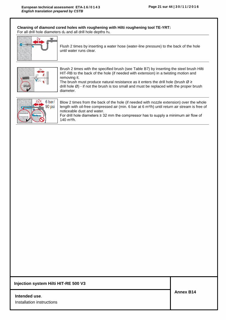
Cleaning of diamond cored holes with roughening with Hilti roughening tool TE-YRT: For all drill hole diameters d0 and all drill hole depths h0.
Flush 2 times by inserting a water hose (water-line pressure) to the back of the hole until water runs clear.
Brush 2 times with the specified brush (see Table B7) by inserting the steel brush Hilti HIT-RB to the back of the hole (if needed with extension) in a twisting motion and removing it. The brush must produce natural resistance as it enters the drill hole (brush Ø ≥ drill hole Ø) - if not the brush is too small and must be replaced with the proper brush diameter.
Blow 2 times from the back of the hole (if needed with nozzle extension) over the whole length with oil-free compressed air (min. 6 bar at 6 m³/h) until return air stream is free of noticeable dust and water. For drill hole diameters ≥ 32 mm the compressor has to supply a minimum air flow of 140 m³/h.

European technical assessment ETA-1 6 / 0 1 4 3 English translation prepared by CSTB
Page 22 sur 44 | 3 0 / 1 1 / 2 0 1 6
Injection system Hilti HIT-RE 500 V3
Annex B15 Intended use.
Installation instructions
Injection preparation
Tightly attach Hilti mixing nozzle HIT-RE-M to foil pack manifold. Do not modify the mixing nozzle. Observe the instruction for use of the dispenser. Check foil pack holder for proper function. Insert foil pack into foil pack holder and put holder into dispenser.
The foil pack opens automatically as dispensing is initiated. Depending on the size of the foil pack an initial amount of adhesive has to be discarded. Discarded quantities are: 3 strokes for 330 ml foil pack, 4 strokes for 500 ml foil pack, 65 ml for 1400 ml foil pack.
Inject adhesive from the back of the drill hole without forming air voids.
Inject the adhesive starting at the back of the hole, slowly withdrawing the mixer with each trigger pull. Fill approximately 2/3 of the drill hole to ensure that the annular gap between the anchor and the concrete is completely filled with adhesive along the embedment length.
After injection is completed, depressurize the dispenser by pressing the release trigger. This will prevent further adhesive discharge from the mixer.
Overhead installation and/or installation with embedment depth hef > 250 mm. For overhead installation the injection is only possible with the aid of extensions and piston plugs. Assemble HIT-RE-M mixer, extension(s) and appropriately sized piston plug (see Table B7). Insert piston plug to back of the hole and inject adhesive. During injection the piston plug will be naturally extruded out of the drill hole by the adhesive pressure.
Setting the element Just before setting an anchor, the drill hole must be free of dust and debris.
Before use, verify that the element is dry and free of oil and other contaminants. Mark and set element to the required embedment depth before working time twork has elapsed. The working time twork is given in Table B6.
For overhead installation use piston plugs and fix embedded parts with e.g. wedges.
Loading the anchor: After required curing time tcure (see Table B6) the anchor can be loaded. The applied installation torque shall not exceed the values Tmax given in Tables B1, B2, B3 and B4.

European technical assessment ETA-1 6 / 0 1 4 3 English translation prepared by CSTB
Page 23 sur 44 | 3 0 / 1 1 / 2 0 1 6
Injection system Hilti HIT-RE 500 V3
Annex B16 Intended use.
Installation instructions
Installation with Seismic filling set (HIT-V and AM 8.8)

European technical assessment ETA-1 6 / 0 1 4 3 English translation prepared by CSTB
Page 24 sur 44 | 3 0 / 1 1 / 2 0 1 6
Injection system Hilti HIT-RE 500 V3
Annex C1 Performances Characteristic resistance under tension load in concrete Design according to “EOTA Technical Report TR 029, 09/2010” or “CEN/TS 1992-4:2009”
Table C1: Characteristic resistance for threaded rods under tension load in concrete
Threaded rod, HIT-V-…, AM…8.8 M8 M10 M12 M16 M20 M24 M27 M30
Installation safety factor
Hammer drilling 21) = inst
2) [-] 1,0
Hammer drilling with Hilti hollow drill bit TE-CD or TE-YD
21) = inst
2) [-] - 1,0
Diamond coring 21) = inst
2) [-] 1,2 1,4
Diamond coring with roughening with Hilti roughening tool TE-YRT
21) = inst
2) [-] - 1,0
Hammer drilling in flooded holes 21) = inst
2) [-] 1,4
Steel failure threaded rods
Characteristic resistance NRk,s [kN] As · fuk
Partial safety factor Grade 5.8 Ms,N [-] 1,5
Partial safety factor Grade 8.8 Ms,N [-] 1,5
Partial safety factor HIT-V-R Ms,N [-] 1,87 2,86
Partial safety factor HIT-V-HCR Ms,N [-] 1,5 2,1
Combined pullout and concrete cone failure
Characteristic bond resistance in non-cracked concrete C20/25 in hammer drilled holes and hammer drilled holes with Hilti hollow drill bit TE-CD or TE-YD and diamond cored holes with roughening with Hilti roughening tool TE-YRT
Temperature range I: 40°C / 24°C Rk,ucr [N/mm2] 18 18 17 16 15 15 14 13
Temperature range II: 70°C / 43°C Rk,ucr [N/mm2] 14 13 13 12 12 11 10 10
Characteristic bond resistance in non-cracked concrete C20/25 in diamond cored holes.
Temperature range I: 40°C / 24°C Rk,ucr [N/mm2] 12 12 12 12 12 11 11 11
Temperature range II: 70°C / 43°C Rk,ucr [N/mm2] 9,5 9 9 9 9 8,5 8,5 8,5
Characteristic bond resistance in non-cracked concrete C20/25 in hammer drilled holes and installation in water-filled holes
Temperature range I: 40°C / 24°C Rk,ucr [N/mm2] 15 15 15 14 13 12 12 11
Temperature range II: 70°C / 43°C Rk,ucr [N/mm2] 12 11 11 10 10 9,5 9 8,5
Factor acc. to section 6.2.2.3 of CEN/TS 1992-4:2009 part 5
k82) [-] 10,1
Characteristic bond resistance in cracked concrete C20/25 in hammer drilled holes and hammer drilled holes with Hilti hollow drill bit TE-CD or TE-YD and diamond cored holes with roughening with Hilti roughening tool TE-YRT
Temperature range I: 40°C / 24°C Rk,cr [N/mm2] 6,5 7,5 8 8 8 8 8 8
Temperature range II: 70°C / 43°C Rk,cr [N/mm2] 5,5 6 6 6 6 6 6 6
Factor acc. to section 6.2.2.3 of CEN/TS 1992-4:2009 part 5
k82) [-] 7,2

European technical assessment ETA-1 6 / 0 1 4 3 English translation prepared by CSTB
Page 25 sur 44 | 3 0 / 1 1 / 2 0 1 6
Injection system Hilti HIT-RE 500 V3
Annex C2 Performances Characteristic resistance under tension load in concrete Design according to “EOTA Technical Report TR 029, 09/2010” or “CEN/TS 1992-4:2009”
Table C1: continued
Threaded rod, HIT-V-…, AM…8.8 M8 M10 M12 M16 M20 M24 M27 M30
Combined pullout and concrete cone failure (continued)
Increasing factors for
Rk in concrete
in hammer drilled holes and hammer drilled holes with Hilti hollow drill bit TE-CD or TE-YD and diamond cored holes
c
C30/37 1,04
C40/50 1,07
C50/60 1,09
in diamond cored holes with roughening with Hilti roughening tool TE-YRT
c C50/60 - 1,0
Concrete cone failure
Factor acc. to section 6.2.3 of CEN/TS 1992-4:2009 part 5
kucr2) [-] 10,1
kcr2) [-] 7,2
Edge distance ccr,N [mm] 1,5 hef
Spacing scr,N [mm] 3,0 hef
Splitting failure
Factor acc. to section 6.2.3 of CEN/TS 1992-4:2009 part 5
kucr2) [-] 10,1
kcr2) [-] 7,2
Edge distance ccr,sp [mm] for
h / hef ≥ 2,0 1,0 hef
2,0 > h / hef > 1,3 4,6 hef - 1,8 h
h / hef ≤ 1,3 2,26 hef
Spacing scr,sp [mm] 2 ccr,sp
1) Parameter for design according to EOTA Technical Report TR 029. 2) Parameter for design according to CEN/TS 1992-4:2009.
ccr,sp
h/hef
1,3
2,0
1,0 hef 2,26 hef

European technical assessment ETA-1 6 / 0 1 4 3 English translation prepared by CSTB
Page 26 sur 44 | 3 0 / 1 1 / 2 0 1 6
Injection system Hilti HIT-RE 500 V3
Annex C3 Performances Characteristic resistance under tension load in concrete Design according to “EOTA Technical Report TR 029, 09/2010” or “CEN/TS 1992-4:2009”
Table C2: Characteristic resistance for internally threaded sleeve HIS-(R)N under tension load in concrete
HIS-(R)N M8 M10 M12 M16 M20
Outer diameter of sleeve d1) = dnom2) [mm] 12,5 16,5 20,5 25,4 27,6
Installation safety factor
Hammer drilling 21) = inst
2) [-] 1,0
Hammer drilling with Hilti hollow drill bit TE-CD or TE-YD
21) = inst
2) [-] 1,0
Diamond coring 21) = inst
2) [-] 1,2 1,4
Diamond coring with roughening with Hilti roughening tool TE-YRT
21) = inst
2) [-] - 1,0
Hammer drilling in flooded holes 21) = inst
2) [-] 1,4
Steel failure
Characteristic resistance HIS-N with with screw grade 8.8
NRk,s [kN] 25 46 67 125 116
Partial safety factor Ms,N [-] 1,5
Characteristic resistance HIS-RN with with screw grade 70
NRk,s [kN] 26 41 59 110 166
Partial safety factor Ms,N [-] 1,87 2,4
Combined pullout and concrete cone failure3)
Characteristic bond resistance in non-cracked concrete C20/25 in hammer drilled holes and hammer drilled holes with Hilti hollow drill bit TE-CD or TE-YD and diamond cored holes with roughening with Hilti roughening tool TE-YRT
Temperature range I: 40°C / 24°C Rk,ucr [N/mm2] 13 13 13 13 13
Temperature range II: 70°C / 43°C Rk,ucr [N/mm2] 10 10 10 10 10
Characteristic bond resistance in non-cracked concrete C20/25 in diamond cored holes.
Temperature range I: 40°C / 24°C Rk,ucr [N/mm2] 8,5 8,5 9 9 9,5
Temperature range II: 70°C / 43°C Rk,ucr [N/mm2] 6,5 6,5 6,5 7 7
Characteristic bond resistance in non-cracked concrete C20/25 in hammer drilled holes and installation in water-filled holes
Temperature range I: 40°C / 24°C Rk,ucr [N/mm2] 11 11 11 11 11
Temperature range II: 70°C / 43°C Rk,ucr [N/mm2] 8,5 8,5 8,5 8,5 8,5
Factor acc. to section 6.2.2.3 of CEN/TS 1992-4:2009 part 5
k83) [-] 10,1

European technical assessment ETA-1 6 / 0 1 4 3 English translation prepared by CSTB
Page 27 sur 44 | 3 0 / 1 1 / 2 0 1 6
Injection system Hilti HIT-RE 500 V3
Annex C4 Performances Characteristic resistance under tension load in concrete Design according to “EOTA Technical Report TR 029, 09/2010” or “CEN/TS 1992-4:2009”
Table C2: continued
HIS-(R)N M8 M10 M12 M16 M20
Combined pullout and concrete cone failure3) (continued)
Characteristic bond resistance in cracked concrete C20/25 in hammer drilled holes and hammer drilled holes with Hilti hollow drill bit TE-CD or TE-YD and diamond cored holes with roughening with Hilti roughening tool TE-YRT
Temperature range I: 40°C / 24°C Rk,cr [N/mm2] 8,5 8,5 8,5 8,5 8,5
Temperature range II: 70°C / 43°C Rk,cr [N/mm2] 7 7 7 7 7
Factor acc. to section 6.2.2.3 of CEN/TS 1992-4:2009 part 5
k82) [-] 7,2
Increasing factors for
Rk in concrete
in hammer drilled holes and hammer drilled holes with Hilti hollow drill bit TE-CD or TE-YD and diamond cored holes
c
C30/37 1,04
C40/50 1,07
C50/60 1,09
in diamond cored holes with roughening with Hilti roughening tool TE-YRT
c C50/60 - 1,0
Concrete cone failure
Factor acc. to section 6.2.3 of CEN/TS 1992-4:2009 part 5
kucr2) [-] 10,1
kcr2) [-] 7,2
Edge distance ccr,N [mm] 1,5 hef
Spacing scr,N [mm] 3,0 hef
Splitting failure
Factor acc. to section 6.2.3 of CEN/TS 1992-4:2009 part 5
kucr2) [-] 10,1
kcr2) [-] 7,2
Edge distance ccr,sp [mm] for
h / hef ≥ 2,0 1,0 hef
2,0 > h / hef > 1,3 4,6 hef - 1,8 h
h / hef ≤ 1,3 2,26 hef
Spacing scr,sp [mm] 2 ccr,sp
1) Parameter for design according to EOTA Technical Report TR 029. 2) Parameter for design according to CEN/TS 1992-4:2009. 3) For design according to CEN/TS 1992-1:2009, the characteristic tension load values bond resistance may be
calculated from the characteristic bond resistance for combined pull-out and concrete cone failure according to:
NRk = Rk · (hef · d1 · ).
ccr,sp
h/hef
1,3
2,0
1,0 hef 2,26 hef
European technical assessment ETA-1 6 / 0 1 4 3 English translation prepared by CSTB
Page 28 sur 44 | 3 0 / 1 1 / 2 0 1 6
Injection system Hilti HIT-RE 500 V3
Annex C5 Performances Characteristic resistance under tension load in concrete Design according to “EOTA Technical Report TR 029, 09/2010” or “CEN/TS 1992-4:2009”
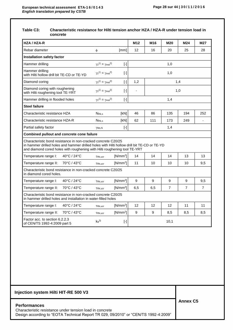
Table C3: Characteristic resistance for Hilti tension anchor HZA / HZA-R under tension load in concrete
HZA / HZA-R M12 M16 M20 M24 M27
Rebar diameter [mm] 12 16 20 25 28
Installation safety factor
Hammer drilling 21) = inst
2) [-] 1,0
Hammer drilling with Hilti hollow drill bit TE-CD or TE-YD
21) = inst
2) [-] 1,0
Diamond coring 21) = inst
2) [-] 1,2 1,4
Diamond coring with roughening with Hilti roughening tool TE-YRT
21) = inst
2) [-] - 1,0
Hammer drilling in flooded holes 21) = inst
2) [-] 1,4
Steel failure
Characteristic resistance HZA NRk,s [kN] 46 86 135 194 252
Characteristic resistance HZA-R NRk,s [kN] 62 111 173 249 -
Partial safety factor Ms,N [-] 1,4
Combined pullout and concrete cone failure
Characteristic bond resistance in non-cracked concrete C20/25 in hammer drilled holes and hammer drilled holes with Hilti hollow drill bit TE-CD or TE-YD and diamond cored holes with roughening with Hilti roughening tool TE-YRT
Temperature range I: 40°C / 24°C Rk,ucr [N/mm2] 14 14 14 13 13
Temperature range II: 70°C / 43°C Rk,ucr [N/mm2] 11 10 10 10 9,5
Characteristic bond resistance in non-cracked concrete C20/25 in diamond cored holes.
Temperature range I: 40°C / 24°C Rk,ucr [N/mm2] 9 9 9 9 9,5
Temperature range II: 70°C / 43°C Rk,ucr [N/mm2] 6,5 6,5 7 7 7
Characteristic bond resistance in non-cracked concrete C20/25 in hammer drilled holes and installation in water-filled holes
Temperature range I: 40°C / 24°C Rk,ucr [N/mm2] 12 12 12 11 11
Temperature range II: 70°C / 43°C Rk,ucr [N/mm2] 9 9 8,5 8,5 8,5
Factor acc. to section 6.2.2.3 of CEN/TS 1992-4:2009 part 5
k83) [-] 10,1

European technical assessment ETA-1 6 / 0 1 4 3 English translation prepared by CSTB
Page 29 sur 44 | 3 0 / 1 1 / 2 0 1 6
Injection system Hilti HIT-RE 500 V3
Annex C6 Performances Characteristic resistance under shear load in concrete Design according to “EOTA Technical Report TR 029, 09/2010” or “CEN/TS 1992-4:2009”
Table C3: continued
HZA / HZA-R M12 M16 M20 M24 M27
Rebar diameter [mm] 12 16 20 25 28
Combined pullout and concrete cone failure (continued)
Characteristic bond resistance in cracked concrete C20/25 in hammer drilled holes and hammer drilled holes with Hilti hollow drill bit TE-CD or TE-YD and diamond cored holes with roughening with Hilti roughening tool TE-YRT
Temperature range I: 40°C / 24°C Rk,cr [N/mm2] 9,5 9,5 10 10 11
Temperature range II: 70°C / 43°C Rk,cr [N/mm2] 8 8 8 8 8
Factor acc. to section 6.2.2.3 of CEN/TS 1992-4:2009 part 5
k82) [-] 7,2
Increasing
factors for Rk in concrete
in hammer drilled holes and hammer drilled holes with Hilti hollow drill bit TE-CD or TE-YD and diamond cored holes
c
C30/37 1,04
C40/50 1,07
C50/60 1,09
in diamond cored holes with roughening with Hilti roughening tool TE-YRT
c C50/60 1,0
Embedment depth for calculation of N0
Rk,p acc. eq. 5.2a (TR 029 §5.2.2.4 )
HZA hef [mm] hnom -20
HZA-R hef [mm] hnom -100 -
Concrete cone failure
Embedment depth for calculation of N0Rk,c
acc. eq. 5.3a (TR 029 §5.2.2.4 ) hef [mm] hnom
Factor acc. to section 6.2.3 of CEN/TS 1992-4:2009 part 5
kucr2) [-] 10,1
kcr2) [-] 7,2
Edge distance ccr,N [mm] 1,5 hef
Spacing scr,N [mm] 3,0 hef
Splitting failure
Factor acc. to section 6.2.3 of CEN/TS 1992-4:2009 part 5
kucr2) [-] 10,1
kcr2) [-] 7,2
Edge distance ccr,sp [mm] for
h / hef ≥ 2,0 1,0 hef
2,0 > h / hef > 1,3 4,6 hef - 1,8 h
h / hef ≤ 1,3 2,26 hef
Spacing scr,sp [mm] 2 ccr,sp
1) Parameter for design according to EOTA Technical Report TR 029. 2) Parameter for design according to CEN/TS 1992-4:2009.
ccr,sp
h/hef
1,3
2,0
1,0 hef 2,26 hef
European technical assessment ETA-1 6 / 0 1 4 3 English translation prepared by CSTB
Page 30 sur 44 | 3 0 / 1 1 / 2 0 1 6
Injection system Hilti HIT-RE 500 V3
Annex C7 Performances Characteristic resistance under shear load in concrete Design according to “EOTA Technical Report TR 029, 09/2010” or “CEN/TS 1992-4:2009”
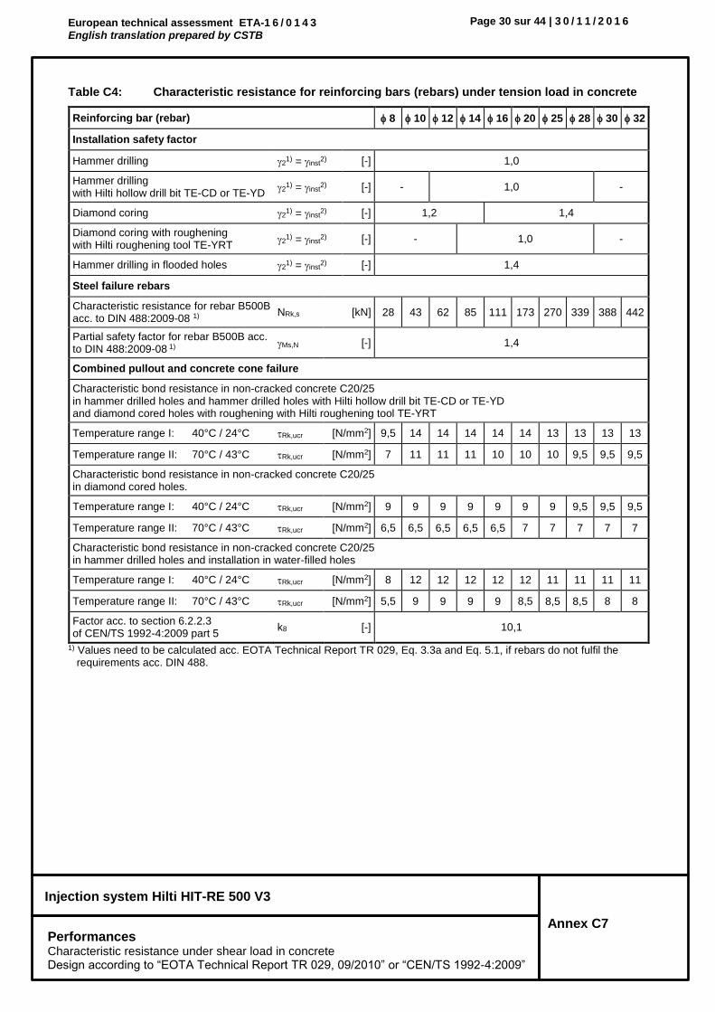
Table C4: Characteristic resistance for reinforcing bars (rebars) under tension load in concrete
Reinforcing bar (rebar) 8 10 12 14 16 20 25 28 30 32
Installation safety factor
Hammer drilling 21) = inst
2) [-] 1,0
Hammer drilling with Hilti hollow drill bit TE-CD or TE-YD
21) = inst
2) [-] - 1,0 -
Diamond coring 21) = inst
2) [-] 1,2 1,4
Diamond coring with roughening with Hilti roughening tool TE-YRT
21) = inst
2) [-] - 1,0 -
Hammer drilling in flooded holes 21) = inst
2) [-] 1,4
Steel failure rebars
Characteristic resistance for rebar B500B acc. to DIN 488:2009-08 1)
NRk,s [kN] 28 43 62 85 111 173 270 339 388 442
Partial safety factor for rebar B500B acc. to DIN 488:2009-08 1)
Ms,N [-] 1,4
Combined pullout and concrete cone failure
Characteristic bond resistance in non-cracked concrete C20/25 in hammer drilled holes and hammer drilled holes with Hilti hollow drill bit TE-CD or TE-YD and diamond cored holes with roughening with Hilti roughening tool TE-YRT
Temperature range I: 40°C / 24°C Rk,ucr [N/mm2] 9,5 14 14 14 14 14 13 13 13 13
Temperature range II: 70°C / 43°C Rk,ucr [N/mm2] 7 11 11 11 10 10 10 9,5 9,5 9,5
Characteristic bond resistance in non-cracked concrete C20/25 in diamond cored holes.
Temperature range I: 40°C / 24°C Rk,ucr [N/mm2] 9 9 9 9 9 9 9 9,5 9,5 9,5
Temperature range II: 70°C / 43°C Rk,ucr [N/mm2] 6,5 6,5 6,5 6,5 6,5 7 7 7 7 7
Characteristic bond resistance in non-cracked concrete C20/25 in hammer drilled holes and installation in water-filled holes
Temperature range I: 40°C / 24°C Rk,ucr [N/mm2] 8 12 12 12 12 12 11 11 11 11
Temperature range II: 70°C / 43°C Rk,ucr [N/mm2] 5,5 9 9 9 9 8,5 8,5 8,5 8 8
Factor acc. to section 6.2.2.3 of CEN/TS 1992-4:2009 part 5
k8 [-] 10,1
1) Values need to be calculated acc. EOTA Technical Report TR 029, Eq. 3.3a and Eq. 5.1, if rebars do not fulfil the requirements acc. DIN 488.

European technical assessment ETA-1 6 / 0 1 4 3 English translation prepared by CSTB
Page 31 sur 44 | 3 0 / 1 1 / 2 0 1 6
Injection system Hilti HIT-RE 500 V3
Annex C8 Performances Characteristic resistance under tension load in concrete Design according to “EOTA Technical Report TR 029, 09/2010” or “CEN/TS 1992-4:2009”
Table C4: continued
Reinforcing bar (rebar) 8 10 12 14 16 20 25 28 30 32
Combined pullout and concrete cone failure (continued)
Characteristic bond resistance in cracked concrete C20/25 in hammer drilled holes and hammer drilled holes with Hilti hollow drill bit TE-CD or TE-YD and diamond cored holes with roughening with Hilti roughening tool TE-YRT
Temperature range I: 40°C / 24°C Rk,cr [N/mm2] 4,5 8,5 9,5 9,5 9,5 10 10 11 11 11
Temperature range II: 70°C / 43°C Rk,cr [N/mm2] 4 7 8 8 8 8 8 8 8 8
Factor acc. to section 6.2.2.3 of CEN/TS 1992-4:2009 part 5
k82) [-] 7,2
Increasing
factors for Rk in concrete
in hammer drilled holes and hammer drilled holes with Hilti hollow drill bit TE-CD or TE-YD and diamond cored holes
c
C30/37 1,04
C40/50 1,07
C50/60 1,09
in diamond cored holes with roughening with Hilti roughening tool TE-YRT
c C50/60 1,0
Concrete cone failure
Combined pullout and concrete cone failure
Factor acc. to section 6.2.3 of CEN/TS 1992-4:2009 part 5
kucr2) [-] 10,1
kcr2) [-] 7,2
Edge distance ccr,N [mm] 1,5 hef
Spacing scr,N [mm] 3,0 hef
Splitting failure
Factor acc. to section 6.2.3 of CEN/TS 1992-4:2009 part 5
kucr2) [-] 10,1
kcr2) [-] 7,2
Edge distance ccr,sp [mm] for
h / hef ≥ 2,0 1,0 hef
2,0 > h / hef > 1,3 4,6 hef - 1,8 h
h / hef ≤ 1,3 2,26 hef
Spacing scr,sp [mm] 2 ccr,sp
1) Parameter for design according to EOTA Technical Report TR 029. 2) Parameter for design according to CEN/TS 1992-4:2009.
ccr,sp
h/hef
1,3
2,0
1,0 hef 2,26 hef

European technical assessment ETA-1 6 / 0 1 4 3 English translation prepared by CSTB
Page 32 sur 44 | 3 0 / 1 1 / 2 0 1 6
Injection system Hilti HIT-RE 500 V3
Annex C9 Performances Characteristic resistance under shear load in concrete Design according to “EOTA Technical Report TR 029, 09/2010” or “CEN/TS 1992-4:2009”
Table C5: Characteristic resistance for threaded rods under shear load in concrete
Threaded rod, HIT-V-…, AM…8.8 M8 M10 M12 M16 M20 M24 M27 M30
Partial safety factor
Steel failure grade 5.8 Ms,v [-] 1,25
Steel failure grade 8.8 Ms,v [-] 1,25
Steel failure HIT-V-R Ms,v [-] 1,56 2,38
Steel failure HIT-V-HCR Ms,v [-] 1,25 1,75
Steel failure without lever arm for threaded rod, HIT-V
Factor according to section 6.3.2.1 of CEN/TS 1992-4 :2009 part 5
k22) [-] 1,0
Characteristic resistance VRk,s [kN] 0,5 · As · fuk
Steel failure with lever arm for threaded rod, HIT-V
Characteristic resistance M0Rk,s [Nm] 1,2 · Wel · fuk
Concrete pry-out failure
Factor in equation (5.7) of TR 029 or acc. to equation (27) of CEN/TS 1992-4 :2009 part 5
k1) = k32) [-] 2,0
Concrete edge failure
See section 5.2.3.4 of TR 029 « Design of bonded anchors »
1) Parameter for design according to “EOTA Technical Report TR 029”. 2) Parameter for design according to CEN/TS 1992-4:2009.

European technical assessment ETA-1 6 / 0 1 4 3 English translation prepared by CSTB
Page 33 sur 44 | 3 0 / 1 1 / 2 0 1 6
Injection system Hilti HIT-RE 500 V3
Annex C10 Performances Characteristic resistance under shear load in concrete Design according to “EOTA Technical Report TR 029, 09/2010” or “CEN/TS 1992-4:2009”
Table C6: Characteristic resistance for for internally threaded sleeve HIS-(R)N under shear load in concrete
HIS-(R)N M8 M10 M12 M16 M20
Steel failure without lever arm
Factor according to section 6.3.2.1 of CEN/TS 1992-4 :2009 part 5
k22) [-] 1,0
Characteristic resistance HIS-N screw class 8.8
VRk,s [kN] 13 23 34 63 58
Partial safety factor Ms,v [-] 1,25
Characteristic resistance HIS-RN screw class 70
VRk,s [kN] 13 20 30 55 83
Partial safety factor Ms,v [-] 1,56 2,0
Steel failure with lever arm
Characteristic resistance HIS-N screw class 8.8
M0Rk,s [Nm] 30 60 105 266 519
Partial safety factor Ms,v [-] 1,25
Characteristic resistance HIS-RN screw class 70
M0Rk,s [Nm] 26 52 92 233 454
Partial safety factor Ms,v [-] 1,56
Concrete pryout failure
Factor in equation (5.7) of TR 029 or acc. to equation (27) of CEN/TS 1992-4 :2009 part 5
k1) = k32) [-] 2,0
Concrete edge failure see TR 029
See section 5.2.3.4 of TR 029 « Design of bonded anchors »
1) Parameter for design according to “EOTA Technical Report TR 029”. 2) Parameter for design according to CEN/TS 1992-4:2009.

European technical assessment ETA-1 6 / 0 1 4 3 English translation prepared by CSTB
Page 34 sur 44 | 3 0 / 1 1 / 2 0 1 6
Injection system Hilti HIT-RE 500 V3
Annex C11 Performances Characteristic resistance under shear load in concrete Design according to “EOTA Technical Report TR 029, 09/2010” or “CEN/TS 1992-4:2009”
Table C7: Characteristic resistance for Hilti tension anchor HZA / HZA-R under shear load in concrete
HZA / HZA-R M12 M16 M20 M24 M27
Rebar diameter [mm] 12 16 20 25 28
Steel failure without lever arm
Factor according to section 6.3.2.1 of CEN/TS 1992-4 :2009 part 5
k22) [-] 1,0
Characteristic resistance HZA VRk,s [kN] 23 43 67 97 126
Characteristic resistance HZA-R VRk,s [kN] 31 55 86 124 -
Partial safety factor Ms,v [-] 1,5
Steel failure with lever arm
Characteristic resistance HZA M0Rk,s [Nm] 72 183 357 617 915
Characteristic resistance HZA-R M0Rk,s [Nm] 97 234 458 790 -
Partial safety factor Ms,v [-] 1,5
Concrete pryout failure
Factor in equation (5.7) of TR 029 or acc. to equation (27) of CEN/TS 1992-4 :2009 part 5
k1) = k32) [-] 2.0
Concrete edge failure see TR 029
See section 5.2.3.4 of TR 029 « Design of bonded anchors »
1) Parameter for design according to “EOTA Technical Report TR 029”. 2) Parameter for design according to CEN/TS 1992-4:2009.

European technical assessment ETA-1 6 / 0 1 4 3 English translation prepared by CSTB
Page 35 sur 44 | 3 0 / 1 1 / 2 0 1 6
Injection system Hilti HIT-RE 500 V3
Annex C12 Performances Characteristic resistance under shear load in concrete Design according to “EOTA Technical Report TR 029, 09/2010” or “CEN/TS 1992-4:2009”
Table C8: Characteristic resistance for reinforcing bars (rebars) under shear load in concrete
Reinforcing bar (rebar) 8 10 12 14 16 20 25 28 30 32
Steel failure without lever arm
Factor according to section 6.3.2.1 of CEN/TS 1992-4 :2009 part 5
k22) [-] 1,0
Characteristic resistance for rebar B500B acc. to DIN 488:2009-08 3)
VRk,s [kN] 14 22 31 42 55 86 135 169 194 221
Partial safety factor for rebar B500B acc. to DIN 488:2009-08 3)
Ms,v [-] 1,5
Steel failure with lever arm
Characteristic resistance M0Rk,s [Nm] 33 65 112 178 265 518 1012 1422 1749 2123
Partial safety factor Ms,v [-] 1,5
Concrete pryout failure
Factor in equation (5.7) of TR 029 or acc. to equation (27) of CEN/TS 1992-4 :2009 part 5
k1) = k32) [-] 2,0
Concrete edge failure see TR 029
See section 5.2.3.4 of TR 029 « Design of bonded anchors »
1) Parameter for design according to “EOTA Technical Report TR 029”.
2) Parameter for design according to CEN/TS 1992-4:2009. 3) Values need to be calculated acc. EOTA Technical Report TR 029, Eq. 3.3b, Eq. 3.3c, Eq. 5.5 and Eq. 5.6b, if rebars
do not fulfil the requirements acc. DIN 488.

European technical assessment ETA-1 6 / 0 1 4 3 English translation prepared by CSTB
Page 36 sur 44 | 3 0 / 1 1 / 2 0 1 6
Injection system Hilti HIT-RE 500 V3
Annex C13 Performances Displacements
Table C9: Displacements for threaded rod under tension load
Threaded rod, HIT-V-…, AM…8.8 M8 M10 M12 M16 M20 M24 M27 M30
Non-cracked concrete
Temperature range I: 40°C / 24°C
Displacement N0 [mm/(N/mm²)] 0,04 0,05 0,05 0,06 0,06 0,07 0,08 0,08
Displacement N [mm/(N/mm²)] 0,10 0,11 0,12 0,13 0,15 0,17 0,18 0,19
Temperature range II: 70°C / 43°C
Displacement N0 [mm/(N/mm²)] 0,05 0,05 0,06 0,07 0,07 0,08 0,09 0,10
Displacement N [mm/(N/mm²)] 0,12 0,13 0,14 0,16 0,18 0,20 0,21 0,23
Cracked concrete
Temperature range I: 40°C / 24°C
Displacement N0 [mm/(N/mm²)] 0,02 0,03 0,05 0,08 0,10 0,13 0,15 0,18
Displacement N [mm/(N/mm²)] 0,12 0,19 0,14 0,19 0,16 0,16 0,15 0,18
Temperature range II: 70°C / 43°C
Displacement N0 [mm/(N/mm²)] 0,02 0,04 0,06 0,09 0,12 0,16 0,18 0,21
Displacement N [mm/(N/mm²)] 0,15 0,23 0,17 0,23 0,19 0,19 0,18 0,21
Table C10: Displacements for threaded rod under shear load
Threaded rod, HIT-V-…, AM…8.8 M8 M10 M12 M16 M20 M24 M27 M30
Displacement V0 [mm/kN] 0,06 0,06 0,05 0,04 0,04 0,03 0,03 0,03
Displacement V [mm/kN] 0,09 0,08 0,08 0,06 0,06 0,05 0,05 0,05

European technical assessment ETA-1 6 / 0 1 4 3 English translation prepared by CSTB
Page 37 sur 44 | 3 0 / 1 1 / 2 0 1 6
Injection system Hilti HIT-RE 500 V3
Annex C14 Performances Displacements
Table C11: Displacements for HIS-N under tension load
HIS-(R)N M8 M10 M12 M16 M20
Non-cracked concrete
Temperature range I: 40°C / 24°C
Displacement N0 [mm/(N/mm²)] 0,05 0,06 0,06 0,07 0,08
Displacement N [mm/(N/mm²)] 0,12 0,13 0,15 0,17 0,18
Temperature range II: 70°C / 43°C
Displacement N0 [mm/(N/mm²)] 0,06 0,07 0,07 0,08 0,09
Displacement N [mm/(N/mm²)] 0,14 0,16 0,18 0,20 0,21
Cracked concrete
Temperature range I: 40°C / 24°C
Displacement N0 [mm/(N/mm²)] 0,05 0,08 0,10 0,13 0,15
Displacement N [mm/(N/mm²)] 0,14 0,19 0,16 0,16 0,15
Temperature range II: 70°C / 43°C
Displacement N0 [mm/(N/mm²)] 0,06 0,09 0,12 0,16 0,18
Displacement N [mm/(N/mm²)] 0,17 0,23 0,19 0,19 0,18
Table C12: Displacements for HIS-N under shear load
HIS-(R)N M8 M10 M12 M16 M20
Displacement V0 [mm/kN] 0,06 0,06 0,05 0,04 0,04
Displacement V [mm/kN] 0,09 0,08 0,08 0,06 0,06

European technical assessment ETA-1 6 / 0 1 4 3 English translation prepared by CSTB
Page 38 sur 44 | 3 0 / 1 1 / 2 0 1 6
Injection system Hilti HIT-RE 500 V3
Annex C15 Performances Displacements
Table C13: Displacements for Hilti tension anchor HZA / HZA-R under tension load
HZA / HZA-R M12 M16 M20 M24 M27
Non-cracked concrete
Temperature range I: 40°C / 24°C
Displacement N0 [mm/(N/mm²)] 0,05 0,06 0,06 0,07 0,08
Displacement N [mm/(N/mm²)] 0,12 0,13 0,15 0,17 0,18
Temperature range II: 70°C / 43°C
Displacement N0 [mm/(N/mm²)] 0,06 0,07 0,07 0,08 0,09
Displacement N [mm/(N/mm²)] 0,14 0,16 0,18 0,20 0,21
Cracked concrete
Temperature range I: 40°C / 24°C
Displacement N0 [mm/(N/mm²)] 0,05 0,08 0,10 0,13 0,15
Displacement N [mm/(N/mm²)] 0,14 0,19 0,16 0,16 0,15
Temperature range II: 70°C / 43°C
Displacement N0 [mm/(N/mm²)] 0,06 0,09 0,12 0,16 0,18
Displacement N [mm/(N/mm²)] 0,17 0,23 0,19 0,19 0,18
Table C14: Displacements for Hilti tension anchor HZA / HZA-R under shear load
HZA / HZA-R M12 M16 M20 M24 M27
Displacement V0 [mm/kN] 0,05 0,04 0,04 0,03 0,03
Displacement V [mm/kN] 0,08 0,06 0,06 0,05 0,05

European technical assessment ETA-1 6 / 0 1 4 3 English translation prepared by CSTB
Page 39 sur 44 | 3 0 / 1 1 / 2 0 1 6
Injection system Hilti HIT-RE 500 V3
Annex C16 Performances Displacements
Table C15: Displacements for rebar under tension load
Reinforcing bar (rebar) 8 10 12 14 16 20 25 28 30 32
Non-cracked concrete
Temperature range I: 40°C / 24°C
Displacement N0 [mm/(N/mm²)] 0,05 0,05 0,05 0,06 0,06 0,07 0,07 0,08 0,08 0,08
Displacement N [mm/(N/mm²)] 0,11 0,11 0,00 0,13 0,15 0,17 0,18 0,19 0,19 0,20
Temperature range II: 70°C / 43°C
Displacement N0 [mm/(N/mm²)] 0,05 0,05 0,06 0,07 0,07 0,09 0,09 0,09 0,10 0,10
Displacement N [mm/(N/mm²)] 0,13 0,13 0,00 0,16 0,18 0,20 0,21 0,22 0,23 0,24
Cracked concrete
Temperature range I: 40°C / 24°C
Displacement N0 [mm/(N/mm²)] 0,03 0,03 0,06 0,08 0,10 0,14 0,15 0,16 0,18 0,19
Displacement N [mm/(N/mm²)] 0,19 0,19 0,06 0,19 0,16 0,16 0,15 0,16 0,18 0,19
Temperature range II: 70°C / 43°C
Displacement N0 [mm/(N/mm²)] 0,04 0,04 0,07 0,09 0,12 0,17 0,17 0,19 0,21 0,22
Displacement N [mm/(N/mm²)] 0,23 0,23 0,07 0,23 0,19 0,19 0,18 0,19 0,21 0,22
Table C16: Displacements for rebar under shear load
Reinforcing bar (rebar) 8 10 12 14 16 20 25 28 30 32
Displacement V0 [mm/kN] 0,05 0,05 0,05 0,04 0,04 0,04 0,03 0,03 0,03 0,03
Displacement V [mm/kN] 0,08 0,08 0,07 0,06 0,06 0,05 0,05 0,05 0,04 0,04

European technical assessment ETA-1 6 / 0 1 4 3 English translation prepared by CSTB
Page 40 sur 44 | 3 0 / 1 1 / 2 0 1 6
Injection system Hilti HIT-RE 500 V3
Annex C17 Performances Characteristic values for seismic performance category C1 and displacements Design according to “EOTA Technical Report TR 045, 02/2013”
Seismic design shall be carried out according TR 045 “Design of Metal Anchors Under Seismic Action”
Table C17: Characteristic resistance for threaded rods under tension loads for seismic category C1 in concrete
Threaded rod, HIT-V-…, AM…8.8 M8 M10 M12 M16 M20 M24 M27 M30
Steel failure threaded rods
Characteristic resistance NRk,s,seis [kN] As · fuk
Combined pullout and concrete cone failure
Characteristic bond resistance in cracked concrete C20/25 in hammer drilled holes and hammer drilled holes with Hilti hollow drill bit TE-CD or TE-YD and diamond cored holes with roughening with Hilti roughening tool TE-YRT
Temperature range I: 40°C / 24°C Rk,seis [N/mm2] 6,0 7,0 7,9 7,9 8,0 8,2 8,3 8,1
Temperature range II: 70°C / 43°C Rk,seis [N/mm2] 4,8 5,7 6,4 6,4 6,5 6,6 6,4 6,1
Table C18: Characteristic resistance for threaded rods under shear loads for seismic category C1 in concrete
Threaded rod, HIT-V-…, AM…8.8 M8 M10 M12 M16 M20 M24 M27 M30
Steel failure without lever arm
Characteristic resistance HIT-V, AM…8.8 VRk,s,seis [kN] 0,5 · As · fuk
Characteristic resistance Commercial standard threaded rod
VRk,s,seis [kN] 0,35 · As · fuk
Table C19: Displacement for threaded rods under tension loads for seismic category C1 in concrete
Threaded rod, HIT-V-…, AM…8.8 M8 M10 M12 M16 M20 M24 M27 M30
Displacement1) N,seis [mm] 2,7 3,0 3,3 3,9 4,5 5,1 5,6 6,0
1) Maximum displacement during cycling (seismic event).
Table C20: Displacement for threaded rods under shear loads for seismic category C1 in concrete
Threaded rod, HIT-V-…, AM…8.8 M8 M10 M12 M16 M20 M24 M27 M30
Displacement1) V,seis [mm] 3,2 3,5 3,8 4,4 5,0 5,6 6,1 6,5
1) Maximum displacement during cycling (seismic event).

European technical assessment ETA-1 6 / 0 1 4 3 English translation prepared by CSTB
Page 41 sur 44 | 3 0 / 1 1 / 2 0 1 6
Injection system Hilti HIT-RE 500 V3
Annex C18 Performances Characteristic values for seismic performance category C1 and displacements Design according to “EOTA Technical Report TR 045, 02/2013”
Table C21: Characteristic resistance for internally threaded sleeve HIS-(R)N under tension load for seismic category C1 in concrete
HIS-(R)N M8 M10 M12 M16 M20
Steel failure
Characteristic resistance HIS-N with with screw grade 8.8
NRk,s,seis [kN] 25 46 67 125 116
Characteristic resistance HIS-RN with with screw grade 70
NRk,s,seis [kN] 26 41 59 110 166
Partial safety factor HIS-N with with screw grade 8.8
Ms,N,seis [-] 1,5
Partial safety factor HIS-RN with with screw grade 70
Ms,N,seis [-] 1,87 2,4
Combined pullout and concrete cone failure
Characteristic bond resistance in cracked concrete C20/25 in hammer drilled holes and hammer drilled holes with Hilti hollow drill bit TE-CD or TE-YD and diamond cored holes with roughening with Hilti roughening tool TE-YRT
Temperature range I: 40°C / 24°C Rk,seis [N/mm2] 8,0 8,0 8,0 8,5 8,5
Temperature range II: 70°C / 43°C Rk,seis [N/mm2] 6,5 6,5 6,5 7,0 7,0
Table C22: Characteristic resistance for internally threaded sleeve HIS-(R)N under shear load for seismic category C1 in concrete
HIS-(R)N M8 M10 M12 M16 M20
Steel failure without lever arm
Characteristic resistance HIS-N with with screw grade 8.8
VRk,s,seis [kN] 9 16 27 41 39
Characteristic resistance HIS-RN with with screw grade 70
VRk,s,seis [kN] 9 14 21 39 58
Table C23: Displacement for internally threaded sleeve HIS-(R)N under tension loads for seismic category C1 in concrete
HIS-(R)N M8 M10 M12 M16 M20
Displacement1) N,seis [mm] 3,4 4,0 4,6 5,3 5,6 1) Maximum displacement during cycling (seismic event).
Table C24: Displacement for internally threaded sleeve HIS-(R)N under shear loads for seismic category C1 in concrete
HIS-(R)N M8 M10 M12 M16 M20
Displacement1) V,seis [mm] 3,9 4,5 5,1 5,8 6,1
1) Maximum displacement during cycling (seismic event).
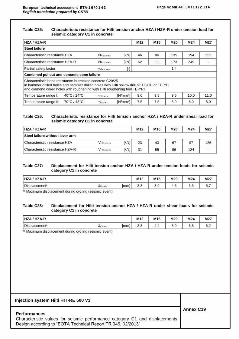
European technical assessment ETA-1 6 / 0 1 4 3 English translation prepared by CSTB
Page 42 sur 44 | 3 0 / 1 1 / 2 0 1 6
Injection system Hilti HIT-RE 500 V3
Annex C19 Performances Characteristic values for seismic performance category C1 and displacements Design according to “EOTA Technical Report TR 045, 02/2013”
Table C25: Characteristic resistance for Hilti tension anchor HZA / HZA-R under tension load for seismic category C1 in concrete
HZA / HZA-R M12 M16 M20 M24 M27
Steel failure
Characteristic resistance HZA NRk,s,seis [kN] 46 86 135 194 252
Characteristic resistance HZA-R NRk,s,seis [kN] 62 111 173 249 -
Partial safety factor Ms,N,seis [-] 1,4
Combined pullout and concrete cone failure
Characteristic bond resistance in cracked concrete C20/25 in hammer drilled holes and hammer drilled holes with Hilti hollow drill bit TE-CD or TE-YD and diamond cored holes with roughening with Hilti roughening tool TE-YRT
Temperature range I: 40°C / 24°C Rk,seis [N/mm2] 9,0 9,5 9,5 10,0 11,0
Temperature range II: 70°C / 43°C Rk,seis [N/mm2] 7,5 7,5 8,0 8,0 8,0
Table C26: Characteristic resistance for Hilti tension anchor HZA / HZA-R under shear load for seismic category C1 in concrete
HZA / HZA-R M12 M16 M20 M24 M27
Steel failure without lever arm
Characteristic resistance HZA VRk,s,seis [kN] 23 43 67 97 126
Characteristic resistance HZA-R VRk,s,seis [kN] 31 55 86 124 -
Table C27: Displacement for Hilti tension anchor HZA / HZA-R under tension loads for seismic category C1 in concrete
HZA / HZA-R M12 M16 M20 M24 M27
Displacement1) N,seis [mm] 3,3 3,9 4,5 5,3 5,7
1) Maximum displacement during cycling (seismic event).
Table C28: Displacement for Hilti tension anchor HZA / HZA-R under shear loads for seismic category C1 in concrete
HZA / HZA-R M12 M16 M20 M24 M27
Displacement1) V,seis [mm] 3,8 4,4 5,0 5,8 6,2
1) Maximum displacement during cycling (seismic event).

European technical assessment ETA-1 6 / 0 1 4 3 English translation prepared by CSTB
Page 43 sur 44 | 3 0 / 1 1 / 2 0 1 6
Injection system Hilti HIT-RE 500 V3
Annex C20 Performances Characteristic values for seismic performance category C1 and displacements Design according to “EOTA Technical Report TR 045, 02/2013”
Table C29: Characteristic resistance for reinforcing bars (rebars) under tension load for seismic category C1 in concrete
Reinforcing bar (rebar) 8 10 12 14 16 20 25 28 30 32
Steel failure rebars
Characteristic resistance for rebar B500B acc. to DIN 488:2009-08 1)
NRk,seis [kN] - 43 62 85 111 173 270 339 388 442
Combined pullout and concrete cone failure
Characteristic bond resistance in cracked concrete C20/25 in hammer drilled holes and hammer drilled holes with Hilti hollow drill bit TE-CD or TE-YD and diamond cored holes with roughening with Hilti roughening tool TE-YRT
Temperature range I: 40°C / 24°C Rk,seis [N/mm2] - 8,0 9,0 9,0 9,5 9,5 10,0 11,0 11,0 11,0
Temperature range II: 70°C / 43°C Rk,seis [N/mm2] - 6,5 7,5 7,0 7,5 8,0 8,0 8,0 8,0 8,0
1) Values need to be calculated acc. EOTA Technical Report TR 029, Eq. 5.1, if rebars do not fulfil the requirements acc. DIN 488.
Table C30: Characteristic resistance for reinforcing bars (rebars) under shear loads for seismic category C1 in concrete
Reinforcing bar (rebar) 8 10 12 14 16 20 25 28 30 32
Steel failure without lever arm
Characteristic resistance for rebar B500B acc. to DIN 488:2009-08 1)
VRk,seis [kN] - 15 22 29 39 60 95 118 135 155
1) Values need to be calculated acc. EOTA Technical Report TR 029, Eq. 5.5 with VRk,seis = 0,7 ∙ VRk,s, if rebars do not fulfil the requirements acc. DIN 488.
Table C31: Displacement for reinforcing bars (rebars) under tension loads for seismic category C1 in concrete
Reinforcing bar (rebar) 8 10 12 14 16 20 25 28 30 32
Displacement1) N,seis [mm] - 3,0 3,3 3,6 3,9 4,5 5,3 5,7 6,0 6,3
1) Maximum displacement during cycling (seismic event).
Table C32: Displacement for reinforcing bars (rebars) under shear loads for seismic category C1 in concrete
Reinforcing bar (rebar) 8 10 12 14 16 20 25 28 30 32
Displacement1) V,seis [mm] - 3,5 3,8 4,1 4,4 5,0 5,8 6,2 6,5 6,8
1) Maximum displacement during cycling (seismic event).

European technical assessment ETA-1 6 / 0 1 4 3 English translation prepared by CSTB
Page 44 sur 44 | 3 0 / 1 1 / 2 0 1 6
Injection system Hilti HIT-RE 500 V3
Annex C21 Performances Characteristic values for seismic performance category C2 and displacements Design according to “EOTA Technical Report TR 045, 02/2013”
Table C33: Characteristic resistance for threaded rod under tension load for seismic category C2 in concrete
Threaded rod, HIT-V-…, AM…8.8 M8 M10 M12 M16 M20 M24 M27 M30
Steel failure threaded rods
Characteristic resistance NRk,s,seis [kN] As · fuk
Combined pullout and concrete cone failure
Characteristic bond resistance in cracked concrete C20/25 in hammer drilled holes and hammer drilled holes with Hilti hollow drill bit TE-CD or TE-YD
Temperature range I: 40°C / 24°C Rk,seis [N/mm2] - - - 5,5 5,4 5,1 - -
Temperature range II: 70°C / 43°C Rk,seis [N/mm2] - - - 4,1 4,1 3,9 - -
Table C34: Characteristic resistance for threaded rods under shear loads for seismic category C2 in concrete
Threaded rod, HIT-V-…, AM…8.8 M8 M10 M12 M16 M20 M24 M27 M30
Steel failure without lever arm, using Hilti seismic filling set
Characteristic resistance HIT-V 8.8 / AM 8.8 VRk,s,seis [kN] - - - 46 77 103 - -
Steel failure without lever arm, without using Hilti seismic filling set
Characteristic resistance HIT-V 8.8 / AM 8.8 VRk,s,seis [kN] - - - 40 71 90 - -
Characteristic resistance Commercial standard threaded rod
VRk,s,seis [kN] - - - 28 50 63 - -
Table C35: Displacement for threaded rods under tension loads for seismic category C2 in concrete
Threaded rod, HIT-V-…, AM…8.8 M8 M10 M12 M16 M20 M24 M27 M30
Displacement DLS N,seis(DLS) [mm] - - - 0,5 0,5 0,4 - -
Displacement ULS N,seis(ULS) [mm] - - - 1,2 0,9 0,8 - -
Table C36: Displacement for threaded rods under shear loads for seismic category C2 in concrete
Threaded rod, HIT-V-…, AM…8.8 M8 M10 M12 M16 M20 M24 M27 M30
Installation with seismic filling set
Displacement DLS, HIT-V 8.8 / AM 8.8 V,seis(DLS) [mm] - - - 1,2 1,4 1,1 - -
Displacement ULS, HIT-V 8.8 / AM 8.8 V,seis(ULS) [mm] - - - 3,2 3,7 1,1 - -
Installation without seismic filling set
Displacement ULS, HIT-V 8.8 / AM 8.8 V,seis(DLS) [mm] - - - 3,2 2,5 2,6 - -
Displacement ULS, HIT-V 8.8 / AM 8.8 V,seis(ULS) [mm] - - - 9,2 7,1 10,2 - -