Deep Active Learning in Science Education: Focusing on the ...

(De) Focusing on Global Light Transport for Active Scene Recovery ∗
Mohit Gupta†, Yuandong Tian†, Srinivasa G. Narasimhan† and Li Zhang‡
† Robotics Institute, Carnegie Mellon University, USA‡ Computer Science Department, University of Wisconsin-Madison, USA
Abstract
Most active scene recovery techniques assume that ascene point is illuminated only directly by the illumina-tion source. Consequently, global illumination effects dueto inter-reflections, sub-surface scattering and volumetricscattering introduce strong biases in the recovered sceneshape. Our goal is to recover scene properties in the pres-ence of global illumination. To this end, we study the in-terplay between global illumination and the depth cue ofillumination defocus. By expressing both these effects aslow pass filters, we derive an approximate invariant thatcan be used to separate them without explicitly modelingthe light transport. This is directly useful in any scenariowhere limited depth-of-field devices (such as projectors) areused to illuminate scenes with global light transport andsignificant depth variations. We show two applications: (a)accurate depth recovery in the presence of global illumina-tion, and (b) factoring out the effects of defocus for correctdirect-global separation in large depth scenes. We demon-strate our approach using scenes with complex shapes, re-flectances, textures and translucencies.
1. Introduction
Light interacts with the world around us in complexways, resulting in phenomena such as inter-reflections, sub-surface scattering and volumetric scattering. These phe-nomena are collectively termed as global light transport orglobal illumination. Historically, the effects of global il-lumination have largely been ignored in the computer vi-sion literature. Most active shape recovery techniques makethe simplifying assumption that a scene point is illumi-nated only directly by the illumination source. In the pres-ence of global illumination, techniques such as photometricstereo [22], shape from shading [11], structured light scan-ning, shape from projector defocus [23] produce erroneousresults. For instance, inter-reflections make concave objectsappear shallower [14]. Sub-surface scattering in translucentobjects can confound structured light based methods, lead-ing to incorrect depths [7]. It is fair to say that most activescene recovery techniques have limited applicability in reallife settings where global illumination is ubiquitous.
The goal of this work is to recover scene properties inthe presence of global illumination. In general, separat-ing the effects of global illumination from a shape cue re-
∗This research was supported in parts by an ONR grant N00014-08-1-0330 and NSF awards CCF-0541307, IIS-0643628 and IIS-0845916.
quires explicit modeling of global light transport. Given thecomplexity of global illumination, this can be intractable.We consider illumination defocus, the depth cue for theshape-from-projector-defocus approach [23]. In this case,we show that global illumination can be separated from thedepth cue without explicitly modeling or measuring lighttransport. The key observation is that both illumination de-focus and global illumination manifest as low pass filtersduring image formation. If the scene is illuminated with aperiodic illumination pattern, we show that the observed ra-diance at each pixel over time can be modeled as a convolu-tion of the input pattern with the two blur kernels associatedwith defocus and global illumination (see Figure 1).
Expressing both the shape cue (defocus) and globalillumination as blur kernels can appear to be counter-productive, as it may make it harder to separate the two.However, illumination defocus and global illumination aredifferent physical phenomena. Illumination defocus is a re-sult of the optics of the source, and encodes scene depths.On the other hand, global illumination encodes the intrinsicproperties of the scene, such as 3D geometry and materialproperties. Thus, although changing the projector focus set-ting changes the defocus blur, the global illumination blurremains approximately constant. Based on this observa-tion, we derive an invariant between global illumination blurand defocused illumination which can be used to separatethe two effects. This invariant is directly useful in scenar-ios where limited depth-of-field devices (such as projectors)are used to illuminate scenes with global light transport andlarge depth variations.
We show two applications which require separation ofdefocus and global illumination:First, accurate depth re-covery in the presence of global illumination (sub-surfacescattering and inter-reflections). We follow the frequencydomain approach of Zhang et al [23] and derive two depthestimation algorithms. The first algorithm requires a sweepof the projector focal plane across the scene and is dualto shape-from-camera-focus techniques. The second algo-rithm requires only two focal plane settings and is simi-lar in spirit to shape-from-camera-defocus methods.Sec-ond, separation of the direct and global components of lighttransport for scenes with depth variations larger than thenarrow depth of field of projectors (< 0.3m). We followthe spatial domain approach of Nayar et al [15] and derivedefocus-invariant measures of global illumination. Again,we present two algorithms for separation based on (a) mul-tiple focal plane positions and (b) single focal plane positionand a depth map estimated in the first application.

(a) Direct Illumination (b) Direct+Indirect Illumination
Figure 1. Image formation model. (a) A periodic illumination pattern is projected on the scene using a projector. The temporal radianceprofiles of scene points which are not in focus are blurred. The amount of defocus blur is a function of the scene depths. (b)The presenceof global light transport due to sub-surface scattering andinter-reflections introduces an additional blur. We show that the blur due to globalillumination is independent of the projector focal plane position. This enables depth recovery even in the presence of global light transport.
We demonstrate our approaches using scenes with com-plex shapes and material properties including (a) marble,wax and natural objects such as fruits, milk and plants thatshow strong subsurface scattering, (b) objects with com-plex reflectance properties and textures such as fur, velvet,metal, wood and (c) objects with occlusions and concavitieswith strong inter-reflections. Since we do not impose anysmoothness constraints, we recover depths independently atevery pixel. Our techniques do not require complex calibra-tion and are simple to implement.
2. Related Work
Most existing shape-from-intensity techniques [22, 11,23] account for only the direct component of light transport.One possibility is to remove the global component a prioriusing the approach of Nayar et al [15]. However, this ap-proach requires the projector’s illumination to be focusedon the entire 3D scene, making it unamenable for depth re-covery using projector defocus analysis. Nayar et al [14] re-covered depths in the presence of inter-reflections for scenesmade of a few Lambertian planar facets. Approaches basedon explicitly measuring the light transport matrix [19, 6] canbe used to remove inter-reflection from images [18]. Suchapproaches require measuring a large number of impulse re-sponses of the scene. Our methods do not require explicitmodeling or estimation of the light transport matrix.
For structured light based techniques, the presence ofsub-surface scattering and inter-reflections hinders the de-tection of the light sheet intersection with the objects [7].Researchers have used polarization [3], modulation witha high-frequency illumination pattern [4] and fluores-cence [12] to mitigate the adverse effects of global illumi-nation. However, polarization does not reduce the effects ofinter-reflections, and the fluorescence based technique re-quires submerging the scene in a fluorescent dye. More-over, as with any triangulation based technique, structuredlighting suffers from the presence of occlusions in com-plex scenes. Depth from camera focus (DFF) [16, 9] anddepth from camera defocus (DFD) [21] techniques can com-
(a) (b)Figure 2. Data acquisition setup. (a) Co-located camera-projectorsetup enables recovery of hole-free depth maps. (b) The periodicpattern used to illuminate the scene.
pute complete depth maps1, but they rely on scene texturefor accurate scene recovery. We use a co-located camera-projector setup for data acquisition, as shown in Figure 2 (a).Using this setup prevents shadows due to occlusions, en-abling recovery of complete, hole-free depth-maps. Also,our techniques can handle scenes with or without textures.
Another class of techniques measure density distributionof volumetric media using active lighting [2, 10, 8]. Con-focal imaging techniques recover partially transparent vol-umes by focusing the illumination and sensor simultane-ously on slices of the volume [5, 13]. The focus of thiswork is reconstructing opaque and translucent surfaces. Itwill be interesting to analyze the effects of volumetric scat-tering and transparency on our techniques in the future.
3. Image Formation Model
Consider a scene being illuminated by a projector witha periodic high frequency pattern. An example pattern isshown in Figure 2 (b). The pattern is translated horizontally,one pixel at a time, and an image is acquired for each trans-lation. In the following, we show that the temporal radiance
1Although DFD and DFF also suffer from occlusion, the effectsare notas severe due to a much smaller base-line [17].

profile at each pixel can be modeled as a convolution of theinput pattern with the two blur kernels associated with illu-mination defocus and global illumination (see Figure 1(b)).
Direct Illumination: Consider the illustration in Fig-ure 1 (a). The direct component of the radianceed
i (t, f) atscene pointSi is the convolution of the illumination pattern,pi(t), and the defocus blur kernelbi(t, f) atSi
2:
edi (t, f) = αi pi(t) ∗ bi(t, f) . (1)
wheret denotes time, andf is the location of the pro-jector focal plane. The blur kernelbi(t, f) depends on thedepth ofSi and the position of the projector focal plane,f . The scale factorαi accounts for the BRDF of the scenepoint, orientation of the surface with respect to the illumi-nation source and the sensor, and the intensity fall-off.
Global Illumination: The global illumination at a scenepointSi is due to radiance received from other scene points,as shown in Figure 1(b). Letmij be the fraction of the di-rect radiance at the scene pointSj that reachesSi, possiblyafter multiple inter-reflections and sub-surface scattering.Then the global componente
gi (t, f) is obtained by adding
the contributions from all other scene points:
egi (t, f) =
∑
Sj∈Scene,j 6=i
mij pj(t) ∗ bj(t, f) . (2)
The total radianceei(t, f) at Si is the sum of the directand the global components:
ei(t, f) = edi (t, f) + e
gi (t, f) . (3)
We compactly write the expression for radiance at scenepointSi using Eqs. 1, 2 and 3:
ei(t, f) =∑
Sj∈Scene
mij pj(t) ∗ bj(t, f) . (4)
We have implicitly included theαi term withmii. Tak-ing the Fourier transform of Eq. 4:
Ei(w, f) = P (w)∑
Sj
mij exp(−I w φj)Bj(w, f) , (5)
where, uppercase symbols denote the Fourier transformsof the corresponding lower-case symbols. The variablewrepresents the frequency. Sincepj(t) is a shifted versionof pi(t), their Fourier transforms have the same magnitudeP (w) and differ only in the phase termexp(−I w φj). Re-arranging the terms:
Ei(w, f) = P (w) Bi(w, f) Gi(w, f) , (6)
Gi(w, f) =∑
Sj
mij exp(−I w φj)Bj(w, f)
Bi(w, f). (7)
2We assume that both incoming and outgoing radiance remain constantwithin the small solid angles (< 1
) subtended by the projector and cameraapertures respectively at the scene point.
The termBi(w, f) is the Fourier transform of the defo-cus blur kernel atSi. This term encodes scene depths and isindependent of global illumination. We defineGi(w, f) asthe Fourier transform of theglobal illumination blur kernelat Si. The termGi(w, f) encodes the optical interactionsbetween different scene points via the light transport coeffi-cientsmij . Thus, the observed blurEi(w, f) is a functionof both the blur due to defocusBi(w, f) and the blur dueto global illuminationGi(w, f). Note that this analysis andthe techniques presented in the paper do not make any as-sumption on the particular form of the blur kernels.
We computeEi(w, f) by taking the Discrete FourierTransform of the observed radiance profile. We use the thirdcoefficient of the DFT (w = 3) as a measure of the amountof blur, as we empirically found it to be the most informa-tive coefficient. In the rest of the paper, for brevity, we dropthe argumentw, i.e. E(w, f), G(w, f) andB(w, f) will bedenoted asE(f), G(f) andB(f) respectively.
4. Invariance of Global Illumination Blur to Il-lumination Defocus
In this section, we establish the invariant that the globalillumination blurG(f) is insensitive to the projector focussettingf . We show this using both real experiments andsimulations. An analytical proof for a particular distributionof scene points and symmetric defocus kernels is given inthe technical report [20].
4.1. Validation using Real Experiments
For the purpose of validation, we measureG(f) for awide range of projector focus settingsf . For a scene pointSi, we can computeGi(f) up to a constant scale factor byidentifying another scene pointSj which does not receiveany global illumination, and has the same depth asSi. UsingEq. 6 and noting thatBi(f) = Bj(f):
Gi(f)
αj
=Ei(f)
Ej(f), (8)
Experimental Setup: We use a co-located camera-projector system as shown in Figure 2 (a). Our system con-sists of a Sony Cineza 3-LCD video projector and a Lumen-era Lu165C12-bit camera. The projector focus setting ischanged by rotating the focus ring manually. Markings weremade on the focus ring to be able to replicate the focus set-tings. We use the pattern shown in Figure 2 (b) to illuminatethe scene. This pattern has a period of24 pixels in the hori-zontal direction [23]. For each focus setting, we acquire24images as the pattern is translated horizontally, one pixelat atime. The total number of images acquired is24×F , whereF is the number of focus settings used. The acquisition timeis approximately 1 minute per focus setting.
Validation Results: We design experiments to establishthe invariant for both sub-surface scattering and inter-reflections. For inter-reflections, we construct a V-grooveusing two diffuse planes, as shown in Figure 3 (a). We com-puteE(f) for the scene pointA for different focus settings,
(a) (b) (c) (f) (g) (h)
1 2 3 4 5 60.04
0.06
0.08
0.1
0.12
Focal Plane Position (f)
E (
f)
No global illuminationWith global illumination
1 2 3 4 5 61
1.2
1.4
1.6
1.8
Focal Plane Position (f)
G (
f) /
α
1 2 3 4 5 6 7 80.02
0.06
0.1
0.14
0.18
Focal Plane Position (f)
E (
f)
No global illuminationWith global illumination
1 2 3 4 5 6 7 80.1
0.2
0.3
0.4
0.5
0.6
0.7
0.8
0.9
Focal Plane Position (f)
G (
f)/α
(d) (e) (i) (j)
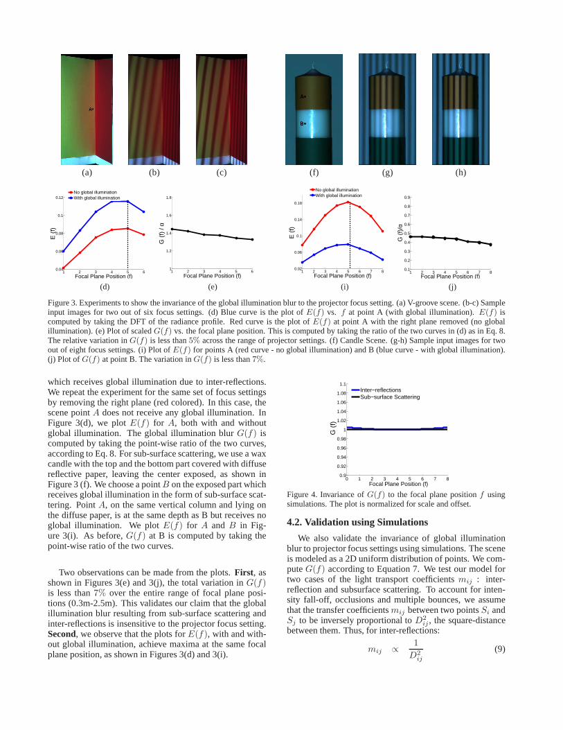
Figure 3. Experiments to show the invariance of the global illumination blur to the projector focus setting. (a) V-groove scene. (b-c) Sampleinput images for two out of six focus settings. (d) Blue curveis the plot ofE(f) vs. f at point A (with global illumination).E(f) iscomputed by taking the DFT of the radiance profile. Red curve is the plot ofE(f) at point A with the right plane removed (no globalillumination). (e) Plot of scaledG(f) vs. the focal plane position. This is computed by taking the ratio of the two curves in (d) as in Eq. 8.The relative variation inG(f) is less than5% across the range of projector settings. (f) Candle Scene. (g-h) Sample input images for twoout of eight focus settings. (i) Plot ofE(f) for points A (red curve - no global illumination) and B (blue curve - with global illumination).(j) Plot of G(f) at point B. The variation inG(f) is less than7%.
which receives global illumination due to inter-reflections.We repeat the experiment for the same set of focus settingsby removing the right plane (red colored). In this case, thescene pointA does not receive any global illumination. InFigure 3(d), we plotE(f) for A, both with and withoutglobal illumination. The global illumination blurG(f) iscomputed by taking the point-wise ratio of the two curves,according to Eq. 8. For sub-surface scattering, we use a waxcandle with the top and the bottom part covered with diffusereflective paper, leaving the center exposed, as shown inFigure 3 (f). We choose a pointB on the exposed part whichreceives global illumination in the form of sub-surface scat-tering. PointA, on the same vertical column and lying onthe diffuse paper, is at the same depth as B but receives noglobal illumination. We plotE(f) for A and B in Fig-ure 3(i). As before,G(f) at B is computed by taking thepoint-wise ratio of the two curves.
Two observations can be made from the plots.First, asshown in Figures 3(e) and 3(j), the total variation inG(f)is less than7% over the entire range of focal plane posi-tions (0.3m-2.5m). This validates our claim that the globalillumination blur resulting from sub-surface scattering andinter-reflections is insensitive to the projector focus setting.Second, we observe that the plots forE(f), with and with-out global illumination, achieve maxima at the same focalplane position, as shown in Figures 3(d) and 3(i).
0 1 2 3 4 5 6 7 80.9
0.92
0.94
0.96
0.98
1
1.02
1.04
1.06
1.08
1.1
Focal Plane Position (f)
G (
f)
Inter−reflectionsSub−surface Scattering
Figure 4. Invariance ofG(f) to the focal plane positionf usingsimulations. The plot is normalized for scale and offset.
4.2. Validation using Simulations
We also validate the invariance of global illuminationblur to projector focus settings using simulations. The sceneis modeled as a 2D uniform distribution of points. We com-puteG(f) according to Equation 7. We test our model fortwo cases of the light transport coefficientsmij : inter-reflection and subsurface scattering. To account for inten-sity fall-off, occlusions and multiple bounces, we assumethat the transfer coefficientsmij between two pointsSi andSj to be inversely proportional toD2
ij , the square-distancebetween them. Thus, for inter-reflections:
mij ∝1
D2ij
(9)

10 50 90 130 170140
150
160
170
180
Pixels
Dep
th (
cms)
One Focal PlaneTwo Focal PlanesMultiple Focal PlanesGround Truth
50 100 150 200 250 30050
100
150
200
Pixels
Dep
th (
cms)
One Focal PlaneTwo Focal PlanesMultiple Focal PlanesGround Truth
(a) (b) (c) (d) (e) (f) (g) (h)
Figure 5. Comparison of the three depth recovery techniquesfor the V-groove and the candle scenes. (a, e) Single focal plane algorithm [23].(b, f) Two Focal Planes (Section 5.2). (c, g) Multiple Focal Planes (Section 5.1). (d) Depth profiles for the V-groove along the indicatedrow. (h) Depth profiles for the candle along the indicated column. The single focal plane algorithm over-estimates the defocus blur in thepresence of inter-reflections and sub-surface scattering resulting in incorrect depth estimates near the concavity and for the exposed parts ofthe candle. On the other hand, the relative RMS error for our algorithms is less than1% for the V-groove and less than5% for the candle.The ground truth depths were acquired using a calibration inclined plane with pre-measured depths.
For sub-surface scattering, the termmij encodes the ad-ditional exponential decay due to attenuation:
mij ∝1
D2ij
exp(−Dij) (10)
For validation, we assume a Gaussian model for defocusblur. The spread of the gaussian is given by the distancebetween the scene point and the focal plane. We sample100000 scene points from the distribution over100 trials.We compute the average global illumination blur over allthe scene points for different focal plane positions. Figure 4shows the simulation results. The global illumination blur,both due to inter-reflections and sub-surface scattering re-mains nearly constant across different focus settings.
5. Depth Recovery under Global Illumination
Based on the invariant derived in the previous section,we present two algorithms for recovering depths in the pres-ence of global light transport. The first algorithm requiresasweep of the focal plane across the scene, acquiring imagesat multiple focus settings. The second algorithm requiresonly two focus settings. Recall that the blur in the intensityprofile measured at a single focal plane setting is a convo-lution of both the defocus blur and the global illuminationblur. Thus, we need intensity profiles atatleasttwo focalsettings in order to separate the two blur kernels.
5.1. Depth from multiple projector focal planes
In this algorithm, the DFT coefficientsE(f) are com-puted for multiple (≥ 3) focal plane positionsf spanningthe depth-range of the scene. Since the global illuminationblur G(f) is invariant tof , the plot ofE(f) againstf re-flects the behavior of the defocus blurB(f). In other words,it attains a maxima when the corresponding scene point isthe best in focus. It follows that scene points at the samedepth but receiving different amounts of global illuminationshare the same maxima location. Two examples are shownin Figures 3(d,i). This suggests the maxima locationf i as aglobal-illumination invariant depth measure:
f i = arg maxf
Ei(f) (11)
The resolution of the depth measure, limited by the num-ber of focal settings used, is improved by interpolating thefocus measuresEi(f) between the discrete focal plane set-tings [16]. As a one time calibration step, we compute aone-to-one mapping between scene depths andf i using aplanar, diffuse reflective board, whose depths are known apriori (see Figure 6 (a)). This mapping, along with the esti-mates off , is used to compute the actual depths for a givenscene. This algorithm can be considered a dual to the shape-from-camera-focus technique, where depths are computedby sweeping the camera focal plane across the scene.
5.2. Depth from two projector focal planes
In this algorithm, we compute depths as a function of adefocus measure defined using only two focal positionsf1
andf2. SinceGi(f) is invariant tof , Gi(f1) = Gi(f2).Using Eq. 6, we define the following ratio measure which isinvariant to global illumination:
Ωi =Ei(f2)
Ei(f1)=
Bi(f2)
Bi(f1). (12)
We compute a mapping (monotonic) between scenedepths andΩi using a planar calibration board, as shownin Figure 6 (b). This mapping, along with the estimates ofΩ is used to compute the actual depths for a given scene.
Results: We demonstrate our algorithms on scenes withcomplex shapes and material properties, and significantglobal illumination. Figure 5 shows results for the V-grooveand the candle scenes. The single focal plane algorithm [23]over-estimates the defocus blur due to inter-reflections andsub-surface scattering resulting in incorrect depth estimatesnear the concavity and for the exposed parts of the candle.Our depth from two planes (Section 5.2) and multiple planes(Section 5.1) algorithms reconstruct both the shapes accu-rately. Theoretically,3 focal planes are sufficient for themultiple focal planes algorithm. For robustness, we used6to 8 focal plane positions. Since we compute depths inde-pendently at every pixel, fine details such as the wick of thecandle are reconstructed as well. The ground truth depths inFigure 5 were acquired using a calibration plane with pre-measured depths.

1 3 5 7 850
100
150
200
250
f
Dep
th (
cms)
0.2 0.25 0.3 0.35 0.4 0.4550
100
150
200
250
Ω
Dep
th (
cms)
(a) (b)Figure 6. Mappings between (a) scene depths and the focus mea-suref , (b) scene depths and the defocus measureΩ.
Similar results can be observed in the more complexscenes of Figure 9 and 10. As before, the single plane algo-rithm over-estimates depths for the candle, and around theconcavity of the V-groove. See the project web-page [1] formore results and comparisons. The striped artifacts visiblein the depth maps are due to aliasing of the illumination pat-tern resulting from limited spatial resolution and non-idealoptics of the projector. The aliasing is mitigated by pre-filtering the pattern before projection.
6. Direct-Global Separation under Defocus
The algorithm proposed in [15] separates the direct andglobal components of light transport with a single projectorfocal plane position. However, in the presence of defocusblur, we need more information. Such a situation wouldarise if the depth range of the scene is larger than the depthof field of the projector. In this section, we present two al-gorithms for separating the direct and global components ofradiance in the presence of defocus blur. The first algorithmuses multiple focal planes, and the second uses a single fo-cal plane along with a depth map of the scene, which can berecovered using approaches of the previous section.
First, we derive the separation equations in the presenceof defocus blur. Suppose we use a high-frequency patternpi(t) with an equal number of on and off pixels to illuminatethe scene. Then, following [15], the max-image,e+(f),computed by taking pixel-wise maximum, receivesapprox-imately half the global component. In the presence of de-focus blur, the illumination pattern gets blurred. However,since the period of the pattern remains the same, this ap-proximation still holds. Thus, using Eqs. 1 and 3, we writethe expression fore+(f) in the presence of defocus:
e+
i (f) = β+
i (f) edi + 0.5 e
gi , (13)
β+
i (f) = maxt pi(t) ∗ bi(t, f) . (14)
whereαi = edi . Note thated
i andegi are the direct and
global components respectively atSi when the scene is fullyilluminated. Similarly, we compute the min-image,e−(f):
e−i (f) = β−i (f) ed
i + 0.5 egi , where (15)
β−i (f) = mint pi(t) ∗ bi(t, f) . (16)
These equations are generalizations of the separationequations given in [15], as they account for defocus
blur as well. The coefficientsβ+
i (f) and β−i (f) depend
on the defocus blur kernelbi(t, f) at Si. If Si is in per-fect focus at the focus settingf , β+
i (f) = 1 andβ−i (f) = 0.
6.1. Separation using multiple focal planes
In this section, we present a separation technique bycomputinge+
i (f) ande−i (f) for multiple focal planes. Weuse a checker-board illumination pattern as in [15]. Using aGaussian interpolation scheme similar to previous section,we computee+
i ande−i , the extrema values ofe+
i (f) ande−i (f) respectively. An example plot for a point on the can-dle is shown in Figure 8 (a). Note that the curve fore−i (f)attains a maximum, while the curve fore−i (f) attains a min-imum. The computed imagese+
i ande−i are the max andmin image respectivelyas if the scene is in perfect focus.Thus, we can write the separation equations as:
e+
i = edi + 0.5 e
gi (17)
e−i = 0.5 egi (18)
The direct and global components can then be computed,respectively, ased
i = e+
i − e−i andegi = 2 e−i .
6.2. Separation using one plane and a depth map
Here, we present an algorithm to compute separation inthe presence of defocus blur using a single focal plane anda depth map of the scene computed using the techniquespresented in Section 5. For a scene pointSi, the direct andthe global component are given using Eqs. 13 and 15:
edi =
e+
i (f) − e−i (f)
β+
i (f) − β−i (f)
, (19)
egi = ei − ed
i , (20)
whereei is the observed intensity when the scene is fullylit. The denominator in Eq. 19 encodes the effects of defo-cus blur, and needs to be eliminated in order to recover thedirect and global components. To this end, we build a map-ping between
(
β+
i (f) − β−i (f)
)
and scene depths using aflat diffuse inclined plane with known depths and no globalillumination, as shown in Figure 8 (b). For a pointSr on theinclined plane, we compute the max and the min images,e+
r (f) ande−r (f) respectively. Then:
β+r (f) − β−
r (f) =e+
r (f) − e−r (f)
er
, (21)
whereer is the intensity atSr when the plane is fullylit. If Sr andSi are at the same depth, we can substitute forthe denominator in Eq. 19 with Eq. 21, to recover the directand global components.
Experiments and results for direct-global separation:For direct-global separation, we use the same setup as fordepth estimation. We illuminate the scene with a checker-board pattern with checkers of size8×8 pixels. The pattern

(a) (b) (c) (d) (e)
(f) (g) (h) (i) (j)
Figure 7. Comparison of the three separation techniques. (a, f) In-put images. The technique in [15] incorrectly estimates thedi-rect component (b, g) and the global component (c, h). The directcomponent is underestimated and the global component is over-estimated on the planes of the V-groove and on the backgroundplane in the candle scene. Correct separation using our multiplefocal planes (d-e) and the single focal plane technique (i-j). Zoominto the images for details.
2 4 6 80.25
0.3
0.35
0.4
0.45
Focal Plane Position
Inte
nsity
[0−
1]
e+
e−
e−
e+
25 50 75 100 125 150
0.4
0.5
0.6
0.7
0.8
0.9
1
Depth (cms)
β+ −
β−
(a) (b)Figure 8. (a) Separation using multiple focal planes. We computethe extrema values ofe+
i(f) ande−
i(f) and use them for separa-
tion in Eqs. 17 and 18. (b) Separation using one focal plane. Map-ping betweenβ+
i(f) − β−
i(f) and scene depths. Given a depth
map of the scene, this mapping is used to recover the correct sepa-ration using Eqs. 19 and 20.
is shifted5 times by3 pixels in both dimensions to acquirea total of25 images per focal setting. The max-image andmin-image are computed by simply taking the pixel-wisemaximum and minimum respectively.
Figure 7 shows the separation results for the candle andthe V-groove scene. First, the focal plane was placed infront of the scene so that the objects are not in focus. Thetechnique in [15] under-estimates the direct component andover-estimates the global component on the planes of the V-groove and on the background plane in the candle scene. Incontrast, our single focal plane algorithm (Section 6.2) re-covers the correct separation, as shown for the candle. No-tice the differences in the direct component on the back-
ground plane and the global component on the covered por-tions of the candle. Our multiple focal planes algorithm re-covers the correct separation as well, as shown for the V-groove. Notice theglow due to inter-reflections around theconcavity in the global component.
We also consider scenes with large depth variations(0.3m - 2m), significantly more than the depth of field ofthe projector, as shown in Figures 9 and 10. Here, for thetechnique in [15], the focal plane was placed in front of thescene, resulting in incorrect separation on the backgroundand the polyresin bust in particular, as shown in Figure 9 (f-g). Our separation algorithms account for the defocus blur,and recover the correct direct and global components. Formore results and comparisons, see the project web-page [1].
7. Discussion and Limitations
We have studied the interplay between defocused illu-mination and global illumination and derived an invariantwhich can be used to separate the two effects for scene re-covery. We now discuss some limitations of our approaches.
If a scene point does not see the entire projector aperture,for example due to occlusions at depth discontinuities, theillumination defocus kernel at that scene point would be un-derestimated. As a result, the two/one plane algorithms areprone to errors close to depth discontinuities. However, themultiple focal plane algorithms rely on identifying the fo-cus setting where there is no defocus. Thus, they are morerobust at depth discontinuities (for instance, the wick of thecandle) as compared to the two/one focal plane algorithms.
Our approaches do not handle perfectly mirrored objectsdue to high frequency global illumination. Another chal-lenging problem is to analyze the effects of volumetric scat-tering and transparency on our techniques. Currently, thedata acquisition process for our algorithms is not real-time.An avenue of future work is to extend our techniques fordynamic scenes. Finally, it will be interesting to accountfor camera defocus to combine the advantages of our tech-niques with those of shape from camera focus/defocus.
References[1] Webpage.http://graphics.cs.cmu.edu/projects/DefocusGlobal/.[2] B. Atcheson, I. Ihrke, W. Heidrich, A. Tevs, D. Bradley,
M. Magnor, and H. Seidel. Time-resolved 3d capture of non-stationary gas flows.SIGGRAPH, 2008.
[3] T. Chen, H. P. A. Lensch, C. Fuchs, and H.-P. Seidel. Po-larization and phase-shifting for 3d scanning of translucentobjects.CVPR, 2007.
[4] T. Chen, H.-P. Seidel, and H. P. A. Lensch. Modulated phase-shifting for 3d scanning.CVPR, 2008.
[5] C. Fuchs, M. Heinz, M. Levoy, H.-P. Seidel, and H. P. A.Lensch. Combining confocal imaging and descattering.Computer Graphics Forum, 27(4), 2008.
[6] G. Garg, E.-V. Talvala, M. Levoy, and H. P. A. Lensch.Symmetric photography: Exploiting data-sparseness in re-flectance fields. InEGSR, 2006.
[7] G. Godin, J.-A. Beraldin, M. Rioux, M. Levoy, L. Cournoyer,and F. Blais. An assessment of laser range measurement ofmarble surfaces. InFifth Conference on optical 3-D mea-surement techniques, 2001.

(a) Scene (b) Depth using multiple planes (Section 5.1) (c) Depth using single plane [23]
(d) Direct (Section 6.1) (e) Global (Section 6.1) (f) Direct[15] (g) Global [15]
Figure 9. Results for the marbles and candle scene. (a) In this scene, we have a wax candle inside a white pot closest to the projector, amarble statue ofatlas, a V-groove and a polyresin bust, in this depth order. The approximate depths of the clay-pot, the marble statue andthe polyresin bust are150cm, 200cm and270cm respectively. (b) Depth map using our multiple planes algorithm. Zoom into the imagesfor details. (c) Incorrect depth map using the single plane algorithm. (d-e) Separation using our multiple planes technique. Since, there isa significant depth variation in the scene, the technique in [15] results in incorrect separation (f-g).
Scene Depth Map (Section 5.1) Direct Component (Section 6.1) Global Component (Section 6.1)
Figure 10. Scene recovery results using our techniques. This scene consists of organic materials: a few peppers, two pumpkins, the greenplant, some marbles and eggs and a flower-pot, in this depth order. See the project web-page [1] for comparisons with previous techniques.
[8] J. Gu, S. K. Nayar, E. Grinspun, P. N. Belhumeur, and R. Ra-mamoorthi. Compressive Structured Light for RecoveringInhomogeneous Participating Media. InECCV, 2008.
[9] S. W. Hasinoff and K. N. Kutulakos. Confocal stereo. InECCV (1), 2006.
[10] T. Hawkins, P. Einarsson, and P. Debevec. Acquisition oftime-varying participating media.SIGGRAPH, 2005.
[11] B. Horn. Obtaining shape from shading information.ThePsychology of Computer Vision, 19(1), 1975.
[12] M. B. Hullin, M. Fuchs, I. Ihrke, H.-P. Seidel, and H. P. A.Lensch. Fluorescent immersion range scanning.SIGGRAPH,2008.
[13] M. Levoy, B. Chen, V. Vaish, M. Horowitz, I. McDowall, andM. Bolas. Synthetic aperture confocal imaging.SIGGRAPH,2004.
[14] S. Nayar, K. Ikeuchi, and T. Kanade. Shape from Interreflec-tions. IJCV, 6(3), 1991.
[15] S. K. Nayar, G. Krishnan, M. D. Grossberg, and R. Raskar.Fast separation of direct and global components of a sceneusing high frequency illumination.SIGGRAPH, 2006.
[16] S. K. Nayar and Y. Nakagawa. Shape from Focus.PAMI,16(8):824–831, 1994.
[17] Y. Y. Schechner and N. Kiryati. Depth from defocus vs.stereo: How different really are they?IJCV, 39(2).
[18] S. M. Seitz, Y. Matsushita, and K. N. Kutulakos. A theoryofinverse light transport. InICCV, 2005.
[19] P. Sen, B. Chen, G. Garg, S. R. Marschner, M. Horowitz,M. Levoy, and H. P. A. Lensch. Dual photography.SIG-GRAPH, 2005.
[20] Y. Tian, M. Gupta, S. G. Narasimhan, and L. Zhang. Rela-tionship between projector defocus and global illuminationfor statistically-modeled scenes. Technical Report CMU-RI-TR-09-10, Carnegie Mellon University, March 2009.
[21] M. Watanabe and S. Nayar. Rational Filters for Passive Depthfrom Defocus.IJCV, 27(3).
[22] R. Woodham. Photometric method for determining surfaceorientation from multiple images.OptEng, 19(1), 1980.
[23] L. Zhang and S. K. Nayar. Projection defocus analysis forscene capture and image display.SIGGRAPH, 2006.